

Page 1

P0603253 555-8421-102
P0609546 555-8421-102
Remote Office and RLC
1.4.2 Release Notes
Product release 1.4.2 Standard 1.1 December 2003
Copyright © 2003 Nortel Networks. All Rights Reserved.
Printed in the United States of America.
All information contained in this document is subject to change without notice. Nortel
Networks reserves the right to make changes to equipment design or program components
as progress in engineering, manufacturing methods, or other circumstances may warrant.
*Nortel Networks, the Nortel Networks logo, the Globemark, Unified Networks, Meridian 1,
Meridian SL-100, and Succession 1000 are trademarks of Nortel Networks.
MICROSOFT, MS-DOS, WINDOWS, WINDOWS 95, WINDOWS 98, WINDOWS ME,
WINDOWS 2000, and WINDOWS NT are trademarks of Microsoft Corporation.
Page 2

Standard 1.1
Publication history
December 2003 This is the Standard 1.1 issue of the Remote Office and RLC
Release Notes for Remote Office Product release 1.4.2. This
document provides updated Known problems and Issues corrected
sections.
2 1.4.2 Release Notes for Remote Office and RLC
Page 3

December 2003
Contents
In this document
About this document 4
What’s new in release 1.4.2? 6
Hardware, software, and documentation requirements 7
Compatibility options 11
Upgrade file names for this release 16
Performing upgrades 17
Important installation notes 19
Impact of delay on voice quality 25
PSTN testing 27
Bridge Ports 31
9150 BRI Configuration property sheet 38
Local Remote Office 9150 unit dialing plan 39
Operation (Remote Office units) 40
Issues Corrected Since 1.4.1 51
Known problems in this release 54
Documentation additions and corrections 61
1.4.2 Release Notes for Remote Office and RLC 3
Page 4

Standard 1.1
About this document
This document applies to the following firmware and software:
Release 1.4.2 firmware for the Remote Office 9150 units and Reach Line
!
Card (RLC)
Release 1.4.2.1 firmware for the Remote Office 911x series units and
!
Meridian Digital Telephone IP Adapter units
Release 1.4.2 software for Remote Office
!
Release 1.4.0 software for Remote Office Configuration Manager
!
Version 33 firmware for ISDN U-interface and ISDN ST-interface
!
Document purpose
This document describes the features, known problems, and work arounds for
the Remote Office 9150 unit, Remote Office 911x series units, Meridian Digital
Telephone IP Adapter units, and the RLC. It also provides:
information that is not provided in the:
!
— Reach Line Card Installation and Administration Guide
(NTP 555-8421-210)
— Remote Office 9150 Installation and Administration Guide
(NTP 555-8421-215)
— Remote Office 911x Series Installation and Administration Guide
(NTP 555-8421-220)
— Meridian Digital Telephone IP Adapter Installation and Administration
Guide (NTP 555-8421-211)
clarification for items that can prevent the system from operating correctly
!
if they are not configured correctly. Refer to “How to achieve a successful
implementation” on page 5 for more details.
4 1.4.2 Release Notes for Remote Office and RLC
Page 5

December 2003
Who should read this document
This document is written for individuals who are responsible for the installation,
configuration, and day-to-day management of the Remote Office 9150 unit,
Remote Office 911x series unit, Meridian Digital Telephone IP Adapter unit,
and RLC.
How to achieve a successful implementation
The instructions provided in the Reach Line Card Installation and
Administration Guide (NTP 555-8421-210) and the Remote Office Installation
Testing—Job Aide help you achieve a successful implementation. Specifically,
pay close attention to the instructions for configuring the following:
PBX configuration for ports, DN Discovery, and Caller ID security
!
PSTN numbers used to contact Remote Office units
!
prefix configuration in PSTN numbers on the RLC
!
BRI trunk configuration on the Remote Office 9150 unit
!
Remote Office naming convention
Unless otherwise specified, the term “Remote Office units” refers to the
following products:
Remote Office 9110 unit
!
Remote Office 9115 unit
!
Remote Office 9150 unit
!
Meridian Digital Telephone IP Adapter unit (Internal and External)
!
PBX terminology
Throughout this document, the term “host PBX” refers to any of the following
Nortel Networks PBX platforms:
Meridian 1
!
Meridian SL-100
!
Succession 1000
!
1.4.2 Release Notes for Remote Office and RLC 5
Page 6

Standard 1.1
What’s new in release 1.4.2?
This is a Remote Office maintenance release. Refer to “Issues Corrected Since
1.4.1” on page 51 for further details.
6 1.4.2 Release Notes for Remote Office and RLC
Page 7

December 2003
Hardware, software, and documentation
requirements
This section identifies the following items that are required to support this
release:
supported PBX platforms and software releases
!
current hardware, firmware, and software versions
!
documentation requirements
!
Meridian 1 software and platforms
The following Meridian 1 platforms are supported using software release 23 (or
later), or are using the Enterprise Business Package:
Options 11, 11(C) Mini, 11(E), 51(C), 61(C), 71(C), and 81(C)
!
Please note the Option 11 Mini platform restrictions shown in the following
table:
Hardware Restrictions
16-port (single-slot) RLC NTDR68xx supported in slots 1, 2, 3 in the main chassis
and 7, 8, 9, 10 in the expander chassis.
32-port (double-slot) RLC NTDR71xx supported in slot 1 or 2 in the main chassis
(maximum of 1) and 7, 8, or 9 in the
expander chassis (maximum of 2).
Since the 32-port RLC requires two backplane connections, it cannot be
provisioned in slot 10 of an Option 11 cabinet, as this slot has only one
backplane connection.
1.4.2 Release Notes for Remote Office and RLC 7
Page 8

Standard 1.1
Package requirements
The following four packages are required in the X11 system software for the
proper functioning of Remote Office with all Meridian 1 systems:
package# 0 BASIC (Basic Call Processing)
package# 19 DDSP (Digit Display)
package# 95 CPND (Caller Party Name Display)
package# 170 ARIE (Meridian Modular Sets)
Currently, all four packages are available in the Basic software bundles for all
Meridian 1 systems.
Meridian SL-100 software and platforms
The following Meridian SL-100 platforms (using software release MSL12 or
later) are supported:
SuperNode (with series 70 Processor)
!
SuperNode SE (with series 70 Processor)
!
Note: Meridian SL-100 platforms require a patch to support M39xx digital
telephone sets with Quality of Service (Qos) transitioning. Refer to the Reach
Line Card Installation and Administration Guide (NTP 555-8421-210) for more
information.
Hardware, software, and firmware
The following table identifies the hardware, software, and firmware supported
by the Meridian 1 release.
Current
Nortel
Product
RLC 16-port NA NTDR68AD NTDR68AA 1.4.2
RLC 32-port IPE-NA NTDR70AD NTDR70AA 1.4.2
Product #
Minimum
Nortel
Product #
Current
Firmware
Available
RLC 32-port Opt 11-NA NTDR71AD NTDR71AA 1.4.2
9150-North American NTDR69AD NTDR69AA 1.4.2
9150-CALA and Asia-Pac NTDR92AD NTDR92AA 1.4.2
9150-Australia/New Zealand NTDR92BD NTDR92BA 1.4.2
8 1.4.2 Release Notes for Remote Office and RLC
Page 9

December 2003
Current
Nortel
Product
RLC 16-port-Euro NTDR68BD NTDR68BA 1.4.2
RLC 32-port IPE-Euro NTDR70BD NTDR70BA 1.4.2
RLC 32-port Opt 11-Euro NTDR71BD NTDR71BA 1.4.2
9150-European NTDR92CD NTDR92AA 1.4.2
9110-Global NTDR76BB 1.4.2
9115-Global NTDR77BB 1.4.2
Meridian Digital Telephone
Internal IP Adapter
Meridian Digital Telephone
External IP Adapter
DSP Module NTDR73AA NTDR73AA N/A
ISDN BRI U-interface module NTDR74AB NTDR74AB 33
ISDN BRI ST-interface module NTDR75AA NTDR75AA 33
Product #
NTDE01BB 1.4.2
NTDE02BB 1.4.2
Minimum
Nortel
Product #
Current
Firmware
Available
Note: With version 1.4.0 of Configuration Manager, you can log on to a unit
with an earlier firmware version to upgrade to the current firmware version.
Remote Office 9150 ISDN BRI Interface information—
for Norway and Sweden only
EN 60950:1992 Annex ZB, Special National conditions, Clause 6.2.1.2 states
that in Norway and Sweden, supplementary insulation for a primary circuit is
required between a Telecommunications Network Voltage (TNV) circuit and
any circuit that has a connection to a protective earthing terminal.
The Remote Office 9150 unit has the ability to support up to four ISDN BRI
circuits. To comply with the specification for supplemental insulation, an
isolation adapter must be placed between each of the Remote Office 9150 unit
BRI inputs and the BRI lines from the service provider.
Isolation adapters are available from local vendors. You can also order the
adapters from Nortel Networks as a merchandise item. The Nortel Networks part
number is P0935714.
1.4.2 Release Notes for Remote Office and RLC 9
Page 10

Standard 1.1
Documentation
To ensure a successful, trouble-free implementation of the RLC, Remote Office
9150 unit, Remote Office 911x series unit, and Meridian Digital Telephone IP
Adapter unit into your network, have the following items available before you
proceed:
core documentation (confirm that you have the most up-to-date documents
!
by checking the Nortel Networks website, as noted under “Obtaining the
documentation”, below).
— this document
— Reach Line Card Installation and Administration Guide
(NTP 555-8421-210)
— Remote Office 9150 Installation and Administration Guide
(NTP 555-8421-215)
— Remote Office 911x Series Installation and Administration Guide
(NTP 555-8421-220)
— Meridian Digital Telephone IP Adapter Installation and Administration
Guide (NTP 555-8421-211)
— Remote Office Network Engineering Guidelines (NTP 555-8421-103)
— Remote Office Product CD-ROM (NTDR81AG)
The Remote Office Product CD-ROM contains firmware and software as
well as documentation in Portable Document Format (PDF).
supplementary documents and job aids:
!
— Remote Office 911x Series Quick Start Guide
— Meridian Digital Telephone IP Adapter Quick Start Guide
— Installer’s Notes for your hardware component (provided in the box)
— Remote Office and RLC Planning Forms (available on the web)
— Remote Office Installation Testing—Job Aide (available on the web)
Obtaining the documentation
You can obtain the documentation from your Nortel Networks distributor, or on
the Worldwide Web at www.nortelnetworks.com. Click on the Technical
Documentation link and navigate to the Remote Office document(s) that you
are interested in reading or downloading.
10 1.4.2 Release Notes for Remote Office and RLC
Page 11

December 2003
Compatibility options
This section contains tables that provide compatibility options for Meridian
Digital Telephone IP Adapters, Remote Office 911x series units, and Remote
Office 9150 units. This section also lists the trunk requirements for Remote
Office release 1.3.
M2000 series (M3310, and M3820 European models) and M39xx series
digital telephone set model and accessory compatibility
The following tables show Remote Office and Meridian Digital Telephone IP
Adapter compatibility with M2000 series (M3310 and M3820 European
models) and M39xx digital telephone set models and accessories.
Meridian Digital Telephone IP Adapter and Remote Office 911x
series units
Meridian Digital
Telephone Internal
IP Adapter
Digital Telephone Set Models
M2008D, M2008HFD ✓✓
M2616D ✓✓
M2216D-ACD
M2616CT Cordless Discontinued Discontinued
M3310, M3820 (Europe only) ✓✓
M3902, M3903
M3904 ✓
M3905 (ACD) ✓
M2000 series (M3310 & M3820 European models) Add-on Modules
Headsets ✓✓
External alert ✓✓
Key-based expansion module ✓✓
ATA (Analog Terminal Adapter)
MCA (Meridian Communications
Adapter)
i
Remote Office 9110
and
✓✓
Meridian Digital
Telephone External
IP Adapter
and
Remote Office 9115
✓
i. The host PBX must be running software capable of supporting each digital telephone
set model used.
1.4.2 Release Notes for Remote Office and RLC 11
Page 12

Standard 1.1
Remote Office 9150 units
Digital Telephone Set Models
i
Remote Office 9150
M2006 ✓
M2008D, M2008HFD
M2616D
M2216D-ACD
✓
✓
✓
M2616CT Cordless Discontinued
M3310, M3820 (Europe only)
M3901
ii
✓
✓
M3902, M3903 ✓
M3904
M3905 (ACD)
✓
✓
M2000 series (M3310 & M3820 European models) Add-on Modules
Headsets ✓
External alert
Key-based expansion module
ATA (Analog Terminal Adapter)
iii
✓
✓
✓
MCA (Meridian Communications Adapter)
✓
i. The host PBX must be running software capable of supporting each digital telephone
set model used.
ii. Refer to “Supported telephone models” on page 63 for required configuration details.
iii. ATA modules support analog telephone sets and facsimile (FAX) machines. ATA
modules do not support modems.
12 1.4.2 Release Notes for Remote Office and RLC
Page 13

December 2003
M39xx series digital telephone set accessory compatibility
The following table shows Meridian Digital Telephone IP Adapter unit, Remote
Office 911x series unit, and Remote Office 9150 unit compatibility with M39xx
series digital telephone set accessories.
Meridian
M39xx series Digital
Telephone Set Accessories
and Add-on Modules
Headsets ✓✓✓
Digital
Telephone IP
Adapter units
Remote Office
911x series
units
Remote Office
9150 units
External alert & recording
interface
Key-based expansion module
(22-button, up to two per
3904/05)
Display-based expansion
module
ATA (Analog Terminal Adapter)
Personal Directory PC utility
Full-duplex Speakerphone
CTI (Computer Telephony
Integration) Adapter
i. The Remote Office 9150 unit supports ATA modules. These modules support analog
telephone sets and facsimile (FAX) machines. They do not support modems.
i
✓✓✓
✓✓✓
✓✓✓
(Refer to Note i)
✓✓✓
✓✓✓
✓✓✓
1.4.2 Release Notes for Remote Office and RLC 13
Page 14
Standard 1.1
Communications system and software requirements
The following table shows the software versions necessary to run Remote Office
products on compatible Nortel Networks’ communications systems.
Remote Office 9150, Remote Office 911x series and Meridian Digital
Telephone IP Adapter units
Communications system
Meridian 1 X11 Release 23 or higher
Meridian SL-100 Release 14 or higher
Succession 1000 Release 1.1 or higher
i. Requires Remote Office software version 1.3 or higher.
Supported Codecs
The following tables show the Codecs supported by the Remote Office and
Meridian Digital Telephone IP Adapter units, as well as the data stream, and
approximate peak bandwidth required by each.
Remote Office 9150 units
CODEC Data stream only
G.711 64 Kbps 78 Kbps
i
Approximate total bandwidth, including IP
overhead (30 ms voice packets)
System software version
G.726 32 Kbps 44 Kbps
G.729A 8 Kbps 22 Kbps
Meridian Digital Telephone IP Adapter and Remote Office 911x
series units
CODEC Data stream only
G.711 64 Kbps 78 Kbps
G.729A 8 Kbps 22 Kbps
14 1.4.2 Release Notes for Remote Office and RLC
Approximate peak bandwidth, including IP
overhead (30 ms voice packets)
Page 15

December 2003
Trunk options for Reach Line Cards
The following is a list of the different trunk options supported by the Reach Line
Card:
VoIP trunk
!
(included through the RLC’s Ethernet interface)
PRI trunk
!
(clear-channel mode)
PRI trunk
!
(56K channel mode)
T1/E1 trunk
!
1.4.2 Release Notes for Remote Office and RLC 15
Page 16

Standard 1.1
Upgrade file names for this release
Firmware and software files are initially provided on the Remote Office Product
CD-ROM (NTDR81AG). Upgrade files that are downloaded from the Nortel
Networks website are provided in self-extracting executable files.
The following table identifies the upgrade files supported by this document for
the Meridian 1 release.
Notes:
If you are using an Meridian SL-100 PBX, contact your Nortel Networks
!
support representative to determine the Meridian SL-100 upgrade file
names.
To check the current firmware follow the procedure at the bottom of page
!
17.
Component
RLC rlc1_4_2.exe rlc-1_4_2.upg
Remote Office 9150 unit 91501_4_2.exe 9150-1_4_2.upg
Remote Office 911x series units 911x1_4_2_1.exe 911x-1_4_2_1.upg
Meridian Digital Telephone
IP Adapter units
(Internal and External)
ISDN BRI U-interface module isdn33.exe bri33u.upg
ISDN BRI ST-interface module isdn33s.exe bri33s.upg
Configuration Manager cm1_4_0.exe not applicable
Obtaining the latest upgrade files
Nortel Networks
delivery file name Upgrade file name
IPadapter1_4_2_1.exe IPAdapter1_4_2_1.upg
Note: The setup.exe file provided within the
cm1_4_0.exe file is used to perform the
Configuration Manager upgrade.
You can obtain the latest upgrade files from your Nortel Networks distributor, or
on the Worldwide Web at www.nortelnetworks.com. Click on the Support link
and navigate to the file(s) that you are interested in.
16 1.4.2 Release Notes for Remote Office and RLC
Page 17

December 2003
Performing upgrades
WARNING
To eliminate any confusion in board numbering, the RLC
automatically sets its Unit ID to 254 with this release when
upgrading from releases prior to 1.2.0.
The RLC now identifies the Remote Office units by their Unit
ID, not by their Unit Number or Node Name. If the Unit ID is
not the same as the Unit Number in the Remote Connection
Configuration on the RLC, the Unit ID in the 9150 or 911x
System Configuration sheet must be changed to match the
Unit Number or Node Name.
To maintain compatibility with all installations that support a
single Remote Office unit, the upgrade process assigns the
default Unit ID of “1” to each unit to match the default at the
RLC. Following an upgrade, administrators responsible for
multiple Remote Office units on a single RLC must configure
the correct Unit ID at each Remote Office unit.
For complete details on performing upgrades, refer to the appropriate
Installation and Administration Guide for your specific product.
ATTE NTI ON
The protocol for communication between the RLC and the
Remote Office units requires that they be running the
same version of firmware for them to communicate with
each other.
Nortel Networks recommends that you perform a firmware upgrade if you are
using older versions of firmware (Release 1.3.4.x or earlier). To check the
version of firmware you are using, do one of the following:
If you are not connected to the device, open Configuration Manager and
!
connect to the Remote Office unit. A window displays the RLC or Remote
Office unit firmware version.
If you are already connected to the device, choose System Information
!
➝
System Data. The unit firmware version displays.
1.4.2 Release Notes for Remote Office and RLC 17
Page 18

Standard 1.1
Each time you perform a firmware upgrade, the configuration database is
converted (if necessary) to a format that is compatible with the new firmware.
The conversion does not affect configuration settings.
To ensure trouble-free communication between the RLC and Remote Office
units during and after the firmware upgrade, Nortel Networks recommends
performing the upgrades as follows:
1 Create backup configuration files for the Remote Office 9150, 911x, and
2 Upgrade the Configuration Manager software on the administration PC.
3 Disable the PBX slot(s) where an RLC is installed.
4 Upgrade the RLC firmware.
Meridian Digital Telephone IP Adapter units and for the RLC. Refer to
“Creating a backup configuration file” in the Installation and Administration
Guide for the specific product.
5 Upgrade the Remote Office 9150, Remote Office 911x series, and Meridian
Digital Telephone IP Adapter unit firmware.
6 Remote Office 9150 units only - Upgrade the BRI module firmware for each
BRI module.
7 Restart the RLC.
8 Restart all units.
9 Re-enable the PBX slot(s).
Note: Upgrade the Remote Office 9150 unit’s firmware before upgrading the
Remote Office 9150 unit’s BRI module firmware.
18 1.4.2 Release Notes for Remote Office and RLC
Page 19

December 2003
Important installation notes
This section provides important information about the installation of the Remote
Office 9150 unit, Remote Office 911x series unit, Meridian Digital Telephone IP
Adapter unit, and RLC.
Advanced Configuration for upgrades
If you have changed the settings in the Advanced Configuration dialog box
(patch releases only), upgrading to product release 1.4.2 from a product release
prior to 1.4.1 returns the settings in this dialog box, listed below, to their default
values. For these default values, refer to page 64.
NLP
!
Dialtone/DTMF Relay
!
Access the Advanced Configuration dialog box through Configuration
Manager’s RLC System Configuration property sheet to ensure that these fields
contain the proper settings for your system. For more information, refer to
“Advanced Configuration” and “Advanced Configuration settings” on pages 63
and 65, respectively, of these Release Notes. This information also appears in
the Remote Office Configuration Manager Help content for this dialog box.
If you are upgrading to product release 1.4.2 from product release 1.4.1, the NLP
and Dialtone/DTMF Relay settings are not set to their default values but instead
stay the same value as they were configured in product release 1.4.1.
Automatic TEIs (Terminal Endpoint Identifiers)
BRI modules must be used in a point-to-point configuration if using automatic
TEI assignments. They cannot be used in a multi-point configuration. You
should also make sure that no other ISDN devices are on the line.
1.4.2 Release Notes for Remote Office and RLC 19
Page 20

Standard 1.1
Class of Service RNGI and RNGB
Class of Service RNGI: Class of Service RNGI permits digital telephones to
ring rather than buzz when they are offhook. Local TCM ports on the RLC
support this feature. However, digital telephone sets connected to Remote Office
units do not support DRG2, DRG3 or DRG4. Digital telephone sets connected to
Remote Office units support DRG1, the default ring.
Class of Service RNGB: Class of Service RNGB, like RNGI, applies ringing to
digital telephones that are idle but offhook, but unlike RNGI it also applies
ringing to digital telephones that are busy and offhook on another line.
Note: These features are only available if there are no local calls present on the
digital telephone set. If a local call is present on the digital telephone set, the
ringer is converted to a beep tone (tone B message).
Connecting a telephone set to a port reserved for Bridge Port
invalidates Bridge Port operation
Do not connect a telephone set to the port that is going to be used as a Bridge
Port. This causes the Bridge Port to fail.
DN Discovery port configuration
Nortel Networks recommends that you run DN Discovery on an unused port,
such as a data port, configured with voice capability. For information on
completing this configuration, refer to the Bridge Port configuration section of
the Remote Office 9150 Installation and Administration Guide
(NTP 555-8421-215).
DSP provisioning for faxes
The G729/FAX compression algorithm now provisions two DSP channels for
each G729/FAX transmission. Refer to “DSP allocation” on page 73 of these
Release Notes for details on how to calculate your DSP needs.
20 1.4.2 Release Notes for Remote Office and RLC
Page 21

December 2003
Flash downloads to M39xx series digital telephone sets
Over an IP network with low delay and packet loss, Flash download times to
remote M39xx digital telephone sets are comparable to PBX wired downloads.
Download times increase when you use PSTN bandwidth on a Remote Office
9150 unit or a Remote Office 911x series unit.
Free-standing key system
Nortel Networks does not support a Remote Office system as a free-standing
key system. If you are searching for free-standing key systems, inquire about the
Norstar and Business Communications Manager product lines.
1.4.2 Release Notes for Remote Office and RLC 21
Page 22

Standard 1.1
Local DN does not support Multiple Appearance directory number
Re-direction Primes (MARPs) on Remote Office units
Local calling at the Remote Office 9150 unit always results in a call’s being
placed to the first port with the dialed number. Multiple DN appearances are not
supported for local calling on the Remote Office 9150 unit. Therefore, you
cannot configure the same DN to local calling keys on multiple digital telephone
sets connected to one Remote Office 9150 unit.
Refer to “DN Discovery” in the Reach Line Card Installation and
Administration Guide (NTP 555-8421-210) for further details.
Local trunk calls
Local trunk numbers cannot be pre-dialed. You must wait for the local trunk dial
tone before dialing the number.
M39xx call log
When you answer an incoming local call, the digital telephone set records the
calling DN in the call log. However, you cannot dial directly from the Call Log,
as the trunk access code and country code do not always appear. To resolve this,
navigate through the call log to the number that you want to dial. Press the Edit
key and the digit(s) of the missing code(s). Press the Done key. To dial the
revised number, press the Dial key.
For example, the call log for an ISDN number displays the digits 4445551212.
The missing trunk access code (9) and country code (0) are required to dial the
number. Use the Edit key to enter the missing digits, 9 followed by 0. The
number now appears in the M39xx’s LCD display as 904445551212. The
end-user can now press the Dial key to place the call from the call log.
Meridian SL-100 telephone diagnostics fail on 2nd slot
On the Meridian SL-100, the second slot of a double-slot card fails during
diagnostic tests. You should simply ignore the diagnostic test.
22 1.4.2 Release Notes for Remote Office and RLC
Page 23

December 2003
Multiple Appearance Directory Number (MADN)
Any active Single Call Ringing (SCR)/Single Call No-ringing (SCN) key causes
the Remote Office unit to allocate DSP and WAN bandwidth for that port. This
is necessary to support a privacy over-ride feature available with the SCR/SCN
key. To avoid unnecessary bandwidth from being utilized, it is recommended
that Multiple Call Ringing (MCR)/Multiple Call No-ringing (MCN) keys be
used for MADN appearances at remote sites. Refer to “Dial tone delay,” on page
43 and “MCR keys increase DSP requirements” on this page for additional
information.
MCR keys increase DSP requirements
In determining the DSP requirements of your Remote Office system, your
calculations must consider the number of ports containing MCR keys. The
over-riding concept to keep in mind when determining DSP requirements is that
each ringing or answered telephone call requires one DSP channel.
The following example assumes one 16-port RLC with no additional DSP
Application Modules for an RLC with eight DSP channels. While one telephone
call is active, which uses one DSP channel, a call to an MCR key assigned to
eight Terminal Numbers (TNs) produces a DSP allocation error. The seven
available DSP channels are insufficient for this call. A non-blocking
configuration must include one DSP channel for each simultaneously ringing or
active digital telephone set that you want to support.
Refer to “Dial tone delay,” on page 43 and “Multiple Appearance Directory
Number (MADN)” on this page for additional information.
PBX and Local feature keys
Local Calling keys on digital telephone sets connected to Remote Office units
cannot have features programmed against them on the host PBX.
Power requirement
If you want to connect the Remote Office 9150 unit to an uninterruptible power
supply (UPS), ensure the UPS has a minimum of 100 Watts available.
1.4.2 Release Notes for Remote Office and RLC 23
Page 24

Standard 1.1
QoS transition recovery
Due to the requirement to support on-demand routers, the IP network is not
continually tested during QoS transition situations. It is tested only when there
are active voice calls over ISDN. As a result, transitioning needs active calls for
the user-configured recovery period in order to switch back to IP.
If you test QoS transition by disconnecting the Ethernet cable from the Remote
Office unit, or RLC, expect up to a 20-second delay before the Remote Office
unit can place or receive a call. You do not encounter this delay when the
network degrades and calls switch to BRI as designed.
Trunk to trunk transfer gives silence
When you transfer a local call using the Trunk Access code to dial an outbound
local call, the corresponding voice path is not established. This function is not
supported.
24 1.4.2 Release Notes for Remote Office and RLC
Page 25

December 2003
Impact of delay on voice quality
The impact of the different voice algorithms (G.729A, G.726, and G.711) is well
documented. G.729A provides 8 to 1 compression and does not produce perfect
voice quality. Most users consider it quite acceptable, although some users claim
that they can hear the difference between it and G.711. The 8 to 1 compression
ratio and the acceptable voice quality make it the codec of choice for Voice over
IP (VoIP). Multiple instances of transcoding (that is, compressing and
decompressing) can have a significant impact on voice quality. G.729A is more
likely to be negatively affected by transcoding than G.711.
Most users do not understand the impact of network/PSTN delay or the impact
of voice compression algorithms on the perceived quality of voice. In order to
compensate for the variation in transmission time across the network (IP and
PSTN), the Remote Office product uses a jitter buffer to allow voice packets to
pass through it in a constant stream. The purpose of the jitter buffer is to remove
the variable delays from the voice packets sent across the network, thus avoiding
awkward-sounding speech. The default value of this jitter buffer is 90
milliseconds (ms).
Note: Once you configure the jitter buffer, the jitter buffer can vary up to 30 ms
above or below the configured target.
To estimate the total delay the user experiences, add the following values:
jitter buffer delay
!
network delay
!
algorithmic encoding delay of the algorithm in use
!
To make the calculation simple, use 30 ms as the algorithmic delay. (It varies
depending on the voice algorithm, but 30 ms is a good estimate).
1.4.2 Release Notes for Remote Office and RLC 25
Page 26

Standard 1.1
The following table indicates one-way delay in ms for the common
configurations. It can seem unusual that the ISDN delay is larger than the IP
delay. However, this is due to the serialization delay of sending the packets
across the relatively low-speed (64K) channels provided by ISDN. (The IP
Network delay assumes high-speed Internet access as part of the intranet.)
G729A
IP Network
Delay
Minimum recommended jitter
buffer setting
Algorithmic delay 30 30 30 30
Reasonable network delay 10 20 20 20
Total One Way Delay 70 80 110 140
30 30 60 90
Over
PSTN
G726 Over
PSTN
G711
Over
PSTN
Excessive delay results in users talking over each other (that is, both users
speaking at the same time). Studies vary as to when this becomes a voice quality
problem, but most of them suggest that this occurs between 120 and 180 ms.
Real-time data transmission produces two types of packet loss:
network-related packet loss (that is, packets lost due to either errors or
!
delays in transmission)
jitter buffer-related packet loss (that is, packets lost due to their being
!
thrown away when the jitter buffer is full)
In effect, there is a trade-off between jitter buffer delay (jitter buffer size) and
packet loss delay at the Remote Office unit. The relationship between jitter
buffer size and packet loss has a direct impact on the user’s perception of voice
quality.
Customer feedback and experience indicate that configuring the jitter buffer to
reduce delay produces better results. Delay, as introduced by the size of the jitter
buffer, is inversely proportional to lost packets. A jitter buffer configuration of
30 ms results in less delay, but a greater likelihood of lost (thrown away)
packets. Most customers find packet loss of 1% far more acceptable than an
increase in one-way delay beyond 180 ms.
26 1.4.2 Release Notes for Remote Office and RLC
Page 27

December 2003
PSTN testing
This is a new feature that has been developed to assist you in testing your
Remote Office 9150 unit’s PSTN connections.
Note: You cannot perform PSTN testing on Remote Office 911x series units.
To avoid common configuration mistakes, Nortel Networks recommends that
you test the PSTN operation after you have finished configuring the PSTN
numbers. In addition, you should only do PSTN testing during periods when the
Remote Office 9150 unit is NOT in use.
PSTN connectivity tests work in two modes:
Disruptive mode
!
Non-disruptive mode
!
In both cases, you can perform the tests on a specified Remote Office 9150 unit
for a specified range of data ports on the RLC. When using the disruptive mode,
Nortel Networks recommends that you wait two or three minutes between tests
to give the Remote Office system time to recover.
You can abort the PSTN tests at any time and return the system to normal
operation mode. The start and end of PSTN tests are recorded as display logs. To
view these display logs, access Configuration Manager
➝
Alarms/Logs/Stats
➝
Display Logs.
WARNING
During PSTN testing, do not make any configuration
changes or perform a Save to Flash on the RLC or
Remote Office 9150 unit involved in the PSTN testing.
If the system reports that it cannot perform PSTN tests, determine the following:
1. Is PSTN enabled on the Remote Office 9150 unit?
2. Is the Remote Office 9150 unit enabled?
Note: During the testing, the system reports the status of the test on each port on
the RLC. The meaning of the status messages are shown in the table on the
following page.
1.4.2 Release Notes for Remote Office and RLC 27
Page 28

Standard 1.1
No Status Message Comments
1 Trunk up Link was brought up successfully to the specified
number and port on the Remote Office unit side.
2 Attempt Failed Attempt made to call specified number failed.
3 Port Busy The specified port is in use; so, it cannot be tested.
4 No Remote Port
Available
There is no Remote Office unit port available to bring
up trunk on specified port.
5 Security Failed There was a security failure while bringing up the trunk.
Check security configuration settings.
6 Abnormal Failure There is an abnormal failure on this connection due to
errors on the line, or due to an emergency call on the
Remote Office 9150 unit.
8 Not Closed In non-disruptive mode, this trunk bandwidth is being
used for the voice calls and so could not be freed.
9 Primary not up If the primary trunk could not be brought up, all
additional trunks show this status.
10 Primary Abnormal Fail All additional trunks show this message if the primary
trunk experiences an abnormal failure during testing.
11 Not data port The specified port is not configured as data port.
12 Attempt by Remote
Failed
Attempt by the Remote Office unit to bring up trunks
from remote side failed.
13 Closed During normal testing process, this message indicates
that a trunk brought up for testing purpose is closed
normally.
14 No Number to Dial Displayed for primary if there is no PSTN number
15 Primary to another unit The specified port is primary to another Remote Office
28 1.4.2 Release Notes for Remote Office and RLC
configured to dial Remote Office 9150 unit, or if the
primary port is in use. Try to do test at a later time and
check PSTN number configuration.
unit. No test can be performed on this port
Page 29

December 2003
Disruptive mode testing
If any voice calls are present on the PSTN when the testing starts, Disruptive
mode testing causes all existing PSTN lines to the specified Remote Office unit
to close abruptly. Before the test starts, however, the system displays a warning
message indicating the number of voice calls present. You must specify that you
want to go ahead with the tests.
In addition, on the Remote Office 9150 unit:
!
!
!
!
Local trunk calls that have occupied Local and Remote configured
B-channels drop.
Remote calls occupying Remote configured B-channel calls drop.
Local calls occupying Remote configured B-channel calls and Emergency
911 calls do not drop.
You cannot place any local outgoing trunk calls on trunk groups that use
Local and Remote B-channels.
Similarly, no incoming local trunk calls are allowed on Local and Remote
!
B-channels.
During disruptive mode testing, the following occurs:
A primary channel is brought up from the RLC side.
!
Other channels are tested from the:
!
— RLC to the Remote Office 9150 unit
— Remote Office 9150 unit to RLC in the given range of data ports of the
RLC
QoS transition is not allowed to happen.
!
No voice calls are allowed to go on the PSTN.
!
The start and end of PSTN tests are recorded as display logs. To view these
!
display logs, access Configuration Manager
➝
Alarms/Logs/Stats
Display Logs.
The user can abort the PSTN tests at any time and system returns to normal
!
operation mode.
➝
1.4.2 Release Notes for Remote Office and RLC 29
Page 30

Standard 1.1
Non-disruptive mode testing
Non-disruptive mode tests do not disturb the operation of your system. The
system functions normally in that:
!
!
!
In addition:
!
!
calls from Remote Office units on PSTN can be made
QoS transition occurs
Remote Office 9150 unit local trunks calls (both incoming and outgoing)
are allowed (including emergency calls)
You may observe that some PSTN lines brought up during the testing
process do not drop automatically.
Sometimes ports that have not been brought up during testing, but were
closed due to the release of PSTN bandwidth are shown as released if they
are in the given range. This depends on how many calls are placed on
PSTN while the test is in progress.
It may not be possible to test some trunks by bringing them up from the
!
RLC or Remote Office 9150 unit and vice versa if they are in use already.
Troubleshooting
If after running the PSTN tests you encounter any PSTN failures, review the
following:
Chapter 4, “Configuring the host PBX for the RLC” in the Reach Line Card
!
Installation and Administration Guide (NTP 555-8421-210)
“Operation (Remote Office units)” on page 40
!
Remote Office Installation Testing—Job Aide section 7, “PSTN Test”
!
30 1.4.2 Release Notes for Remote Office and RLC
Page 31

December 2003
Bridge Ports
Bridge Ports provide integration between the host PBX dialing plan and the
Remote Office 9150 unit local dialing plan. To determine the correct Bridge Port
configuration for your particular Remote Office network, you must first consider
the resource usage of both the Remote Office 9150 unit and RLC. The examples
on pages 33–36 illustrate the most common resource usage scenarios in a
Remote Office network. Configure a Bridge Port TN on the host PBX as a voice
port. For further information, refer to the Reach Line Card Installation and
Administration Guide (NTP 555-8421-210). For Remote Office 9150 Bridge
Port configuration, refer to the Remote Office 9150 Installation and
Administration Guide (NTP 555-8421-215).
Terminology
In the following configuration examples, a local call is defined as a call that
terminates on a Local Calling key of a digital telephone set connected to a
Remote Office 9150 unit. This call can be from another local user, or an inbound
call from the PSTN through the BRI circuits on the Remote Office 9150 unit.
The primary DN is the first key on the digital telephone set connected to Remote
Office 9150 unit that has a DN provided by the host PBX.
Note: Bridge Ports use the primary DNs of Local and Remote digital telephone
sets connected to Remote Office 9150 units to transfer local calls to the host
PBX or to conference host PBX calls to local calls. The primary line key must
be idle for the Bridge Port to function properly. When transferring and
conferencing local calls, Bridge Port connections are established from the
primary DN on the digital telephone set of the local call. If the primary DN of
the digital telephone set connected to the Remote Office 9150 unit is in use, then
the Bridge Port cannot be established.
1.4.2 Release Notes for Remote Office and RLC 31
Page 32

Standard 1.1
Configuration scenarios
The following configuration scenarios show options for enabling conference and
voice mail functionality at remote locations through Remote Office’s Bridge
Port feature.
Basic Bridge Port configuration
Local inbound calls ring on digital telephone sets connected to a Remote Office
9150 unit and can be forwarded or conferenced to the host PBX through the
following configuration:
1 Configure and enable DN Discovery on the RLC.
Note: DN Discovery replaces the DN configured on the Local Calling key of
each digital telephone set connected to a Remote Office 9150 unit with the
DN configured for the first call-capable key programmed for that digital
telephone set on the host PBX, such as Key 0 or Key 1.
2 Configure the Local Calling keys of each digital telephone set connected to a
Remote Office 9150 unit as required.
Note: One MADN can only appear as a local key on one digital telephone
set connected to a given Remote Office 9150 unit. All other appearances of
this MADN on digital telephone sets connected to that same Remote Office
9150 unit must be as host keys.
3 Configure the BRI trunk groups to alert the required local DNs when inbound
calls are received on the BRI lines.
4 Configure enough Bridge Ports to provide the level of call blocking desired.
For example, if four inbound BRI calls are forwarded to the host PBX then
you require four Bridge Ports.
5 Review the DSP channel requirements. Each Bridge Port call requires a
DSP channel and the associated bandwidth.
When a local call is presented and answered on a digital telephone set connected
to a Remote Office 9150 unit, you can then press the Transfer (or Conference)
key. The call indicator of the primary DN key then lights, you hear a host PBX
dialtone, and you can proceed to dial.
Note: Your primary DN is used to conference a local call. The Bridge Port
connects the local user to the host PBX, the Remote Office 9150 unit connects
your primary DN to the host PBX, and the Conference feature on the host PBX
ties it all together.
32 1.4.2 Release Notes for Remote Office and RLC
Page 33

December 2003
Scenario 1
BRI circuits a lert local
1
key L2000 on
reception telephone
9150
9150
9150
Bridge
Bridge
Port(s)
Port(s)
3
Remote Office Bandwidth
Connectivity
WAN or PSTN
RLC
4
host PBX
PSTN caller gets voice
mail greeting from
mailbox 5000
Voice
Voice
Mail
Mail
(8000)
(8000)
Voice Mail
System
7
6
2
Reception - DN 2000 with local key
L2000, call forward-no answers to
Phantom DN 5000 on PBX through
Bridge Port. Telephone also has an
Extended Message Waiting Key
(XMWK) of 5000.
Build a Phantom TN
on in the PBX
For example: DN=5000
forw ard 1 ring to voice
mail DN (8000)
5
The reception digital telephone set (L2000) answers all local BRI calls. Calls
that are not answered use a Bridge Port to transfer to a dedicated remote site
voice mailbox for the entire Remote Office 9150 unit.
Local BRI calls ring the local key(s) of a reception telephone (L2000).
!
These calls, when unanswered, call forward-no answer according to the
!
Remote Office 9150 unit’s 9150 Port Configuration property sheet settings
to a PBX Phantom TN (5000).
This PBX Phantom TN forwards after one ring to the voice mail target DN
!
(8000).
A designated mailbox, such as mailbox number 5000, is built in voice mail.
!
An Extended Message Waiting Key (XMWK) of 5000 on the reception
!
telephone notifies the user of voice mail messages left from Remote Office
9150 unit BRI calls.
Note: An XMWK can be added to any or all digital telephone sets attached
to a Remote Office 9150 unit.
1.4.2 Release Notes for Remote Office and RLC 33
Page 34

Standard 1.1
Scenario 2
BRI circuits a lert local
1
key L2000 on
reception telephone
9150
9150
Bridge
Bridge
Port(s)
Port(s)
9150
2
Reception - DN 2000 with local key
L2000, call forward-no answers to
Phantom DN 5000 on the PBX through
a Bridge Port.
3
Remote Office Bandwidth
Connectivity
WAN or PSTN
RLC
4
host PBX
5
Build a Phantom TN on
in the PBX
For example: DN=5000
forw ard 1 ring to voice
mail DN (8000)
PSTN caller receives
voice mail greeting
from mailbox 2000
Voice
Voice
Mail
Mail
(8000)
(8000)
Voice Mail
System
In voice ma il,
In voice ma il,
build an
build an
associated DN
associated DN
or Alias for the
or Alias for the
users prime DN
users prime DN
(2000)
(2000)
6
7
All calls alert the reception telephone local key (L2000). Unanswered calls
transfer to the receptionists personal voice mailbox (2000).
Local BRI calls ring the local keys of a reception telephone (4000).
!
These calls, when unanswered, call forward-no answer according to the
!
Remote Office 9150 unit’s 9150 Port Configuration property sheet settings
to a PBX Phantom TN (5000).
This PBX Phantom TN forwards after one ring to the voice mail target DN
!
(8000).
The voice mail system has a mailbox for DN 2000. You must add an
!
“Alias” (Octel Terminology) or “Associated/Extension DN” (Meridian
Terminology) of 5000 to the DN mailbox for 2000.
Once this call arrives in voice mail, the “Alias” or “Associated/Extension
!
DN” sends this PSTN call to the personal voice mailbox for DN 2000.
34 1.4.2 Release Notes for Remote Office and RLC
Page 35

December 2003
Scenario 3
BRI circuits a lert local
1
key L2000 on
reception telephone
Reception-DN 2000 with local key
L2000, transfers call to DN 3000. DN
3000 does not answer the call. Call
forward no-answer in the 9150 port for
DN 3000 call forwards to a Phantom
DN of 6000 through a Bridge Port.
9150
DN 3000
2
9150
9150
Bridge
Bridge
Port(s)
Port(s)
3
Remote Office Bandwidth
Connectivity
WAN or PSTN
RLC
4
host PBX
5
Build a Phantom TN
on in the PBX
For example: DN =
6000 forward 1 ring to
voice mail DN (8000)
PSTN caller gets voice
mail greeting from
mailbox 3000
Voice
Voice
Mail
Mail
(8000)
(8000)
Voice Mail
System
In vo ice ma il ,
In vo ice ma il ,
build an
build an
associated DN
associated DN
or Alias for the
or Alias for the
users prime DN
users prime DN
(3000)
(3000)
6
7
All calls alert the reception telephone local key (L2000). The receptionist
answers these calls and then transfers them to other DNs on the Remote Office
9150 unit. If the calls are not answered after the transfer, the calls are placed in
that users personal voice mailbox.
Local BRI calls ring the local keys of a reception telephone (L2000).
!
When answered, these calls transfer to other DNs on the Remote Office
!
9150 unit (3000).
The user at DN 3000 is away and this call transfers to the user’s personal
!
voice mailbox.
This port in 9150 Port Configuration or DN 3000 is enabled to call
!
forward-no answer to a Phantom DN (6000) configured in the PBX.
This PBX Phantom TN forwards after one ring to the voice mail target DN
!
(8000).
The voice mail system has a mailbox for DN 3000. You must add an
!
“Alias” (Octel Terminology) or “Associated/Extension DN” (Meridian
Terminology) of 6000 to the DN mailbox for 3000.
Once this call arrives in voice mail, the “Alias” or “Associated/Extension
!
DN” sends this PSTN call to DN 3000 personal voice mailbox.
1.4.2 Release Notes for Remote Office and RLC 35
Page 36

Standard 1.1
Scenario 4
BRI circuits a lert
1
prime PBX DN 9150
telephone(s)
9150
Local Configuration
on the 9150 ports
are set to non-PBX
dialing plan DNs.
DN 3000
2
9150
9150
Bridge
Bridge
Port(s)
Port(s)
WAN or PSTN
Tromboned call (Bridge
3
Port uses double
resources)
4The call is
presented to the
9150 users primary
PBX DN key.
Remote Office Bandwidth
Connectivity
RLC
host PBX
6
PSTN caller gets voice
mail greeting from users
PBX DN mailbox
Voice
Voice
Mail
Mail
(8000)
(8000)
Voice Mail
System
5
If the call is not answered
on the PB X, it receives
the same treatment as
any other call to that key.
All local inbound calls pass immediately to the host PBX and then are
“trombone” re-directed to the Remote Office 9150 units user’s primary PBX DN
key.
ATTE NTI ON
Disable DN Discovery. This forces the Remote Office 9150 unit to use
!
This scenario creates tromboning on every call and uses
double DSP and bandwidth resources. Not only does this
trombone add additional delay but you MUST also ensure that
the DSP and bandwidth resources allow for this situation. The
duel encoding of voice calls causes further degradation of
voice quality, which can be unacceptable to some users.
Additionally, with DN Discovery disabled, Local Switchover
cannot be used. Therefore, all calls within the Remote Office
9150 unit’s local office require DSP and bandwidth resources.
local DNs (non-PBX DNs) and does not replace the local DN with the
primary PBX DN.
Configure enough Bridge Ports to provide the desired level of call
!
blocking. For example, four inbound BRI calls forwarded to the host PBX
require four Bridge Ports.
36 1.4.2 Release Notes for Remote Office and RLC
Page 37

December 2003
!
!
Note: This configuration provides a local presence for a Remote Office 9150
unit user while maintaining full usage of the host PBX voice mail resources. For
example, an office can publish one of the BRI DNs (such as, 555-1212) as a
direct number. Calls to this DN alert the user’s Remote Office 9150 unit digital
telephone set. They pass from the BRI to the Bridge Port, trombone to the host
PBX, then to the primary DN on the user’s digital telephone set. If the digital
telephone set is busy, regular call treatment occurs, including directing the call
to the user's voice mailbox.
Ensure that the DNs configured for the Remote Office 9150 unit’s local
ports are not the same as any host PBX DNs.
On Configuration Manager’s Trunk Group Configuration property sheet,
configure the user's primary PBX DN in one of the Local DN to Alert
fields.
1.4.2 Release Notes for Remote Office and RLC 37
Page 38

Standard 1.1
9150 BRI Configuration property sheet
This topic provides important information about the BRI Configuration property
sheet. To access this property sheet, go to Configuration Manager
BRI Configuration.
Disabling Multiple Subscriber Number (MSN)
Remote Office requires the ISDN numbers to be unique per module for PSTN
connections between the RLC and Remote Office 9150 unit.
Do not configure B-channels as Local and Remote if MSN is disabled.
For Remote Office 9150 units with multiple BRI modules:
➝
9150
➝
Configure a maximum of one BRI module as Remote Only if PSTN
!
connections are required.
Configure all other BRI modules as Local only.
!
For Remote Office 9150 units with just one BRI module the BRI module can be
configured as Local only or Remote only. If local ISDN calls and remote calls
over PSTN are required, then MSN must be enabled.
Permanent PSTN connection
When using multiple Remote Office units, you must only configure the
permanent PSTN connections for the RLC’s primary network ports. If you only
use one Remote Office unit, you can use additional permanent PSTN
connections.
38 1.4.2 Release Notes for Remote Office and RLC
Page 39

December 2003
Local Remote Office 9150 unit dialing plan
The Remote Office 9150 unit discovers the DN numbers of the local digital
telephones either through DN Discovery or configuration. The Bridge Ports,
Local Calling, and Local SwitchOver features depend on this knowledge as
follows:
If a call has an appearance on a Local Calling key, the Remote Office 9150
!
unit first attempts to complete the operation (for example, call, transfer,
forward) using the local dialing plan.
If a call is placed from a Local Calling key to a number not found in the
!
Remote Office 9150 unit’s local list, then a Bridge Port is used to place the
intended call to the host PBX.
1.4.2 Release Notes for Remote Office and RLC 39
Page 40

Standard 1.1
Operation (Remote Office units)
This section provides important information about the operation of the Remote
Office units off of a Meridian 1, Meridian SL-100, or Succession 1000 PBX.
ATTE NTI ON
ACD environments
If communication is lost to the Remote Office unit, or the unit goes offline, the
ACD agent is placed in Make Set Busy (MSB) mode. This mode logs the agent
out of the ACD queue, so calls can be routed to other ACD agents. Once you
re-establish communication, the digital telephone set display shows “Set Busy
Activated”.
When an ACD agent is on a call using a Local Calling key, the Remote Office
9150 unit sends a transparent Not Ready key press to the host PBX and places
the ACD agent’s digital telephone set in Not Ready mode. This feature prevents
the ACD agent from receiving calls when active on a local call. The Remote
Office 9150 unit removes the digital telephone set from the Not Ready mode
when the agent terminates the local call.
Complete all Remote Office configuration using Configuration
Manager. Only use the man-machine interface (MMI) with the
assistance of technical support personnel for troubleshooting
and diagnostic testing.
If you are having trouble with ACD agents being logged off unexpectedly or
calls that terminate prematurely, try the following:
Set the User On Demand Idle Timer to 90 seconds and the User On
!
Demand Minimum Call Timer to one second.
Note: You can find these settings on the RLC’s Remote Connection
Configuration property sheet in Configuration Manager.
Allocate a permanent connection for the ACD agents.
!
— On the RLC Port Configuration property sheet, click on the Configure
button for the Network Port in question.
— In the Network Port Configuration dialog box, select Permanent
Allocation.
40 1.4.2 Release Notes for Remote Office and RLC
Page 41

December 2003
Analog ports
The analog port (port 64) on a Remote Office 9150 unit is intended to provide
intra-office support according to these conditions:
The port provides the basic functionality of a POTS line, such as:
!
— dial tone
— DTMF tones
— local ringback
— other standard tones
— ring trip voltage for ringing a telephone or a fax machine
The port does not provide the following functionalities:
!
— disconnect supervision
— hook switch flash
— Message Waiting functionality
To make and receive local calls on the analog port or an ATA configured to a
Local and Remote port, configure a local DN to that port. You must then include
that port in a trunk group for it to receive inbound voice or fax calls. To place an
outbound voice or fax call on this port, you must enter the Local Calling SPRE
Code to obtain a local dial tone.
Because an analog port does not have disconnect supervision, a user must place
the device connected to that port on-hook to end a call. If the user does not place
the device connected to the analog port on-hook to end a call, it does not ring for
subsequent calls.
Auto Answer Back on M26xx series digital telephone sets connected
to Meridian SL-100 PBXs produces no dial tone
Auto Answer Back (AAB) activation on M26xx series digital telephone sets on
Remote Office units connected to Meridian SL-100 PBXs does not produce a
dial tone. The digital telephone sets operate properly, but no dial tone is present.
To produce dial tone in this situation, configure the port on the RLC as a TAPI
port.
1.4.2 Release Notes for Remote Office and RLC 41
Page 42

Standard 1.1
Bridge Port does not release when calling party terminates the call
When the calling party terminates a call on a Bridge Port, you must ensure that
both sides of the connection release in order for the Bridge Port to release.
Changing IP parameters and using Save to Flash terminates the calls
When you change System or IP configuration and Save to Flash, calls can be
dropped. Ensure that there are no active calls when you make changes to these
configuration parameters.
Classless Inter-Domain Routing (CIDR) not supported
Remote Office does not support Classless Inter-Domain Routers (CIDRs). For
more information, refer to “Remote Office 911x series unit telephone set menu
allows CIDR configuration (Q00609432)” on page 57.
Configuration Manager access of Remote Office devices not possible
with a modem
It is not possible to use Configuration Manager to configure a Remote Office
unit or RLC over a modem connection.
CRC errors on the High-level Data Link Control (HDLC) do not match
the ISDN interface
The CRC errors that Trunk Protocol reports on the Remote Office product are
check performed end-to-end at the HDLC framing level. This check includes the
ISDN framing errors as well as PSTN spans and clocking issues. The CRC error
count does not always indicate that there are CRC errors on the physical line
between the Remote Office 9150 unit and the CO, or the host PBX and the CO.
However, the CRC error count is a good indication that you need to investigate
the physical line.
42 1.4.2 Release Notes for Remote Office and RLC
Page 43

December 2003
Dial tone delay
Telephone sets connected to Remote Office units can experience unexpectedly
long dial tone delay. Specific delays depend on the number of associated MADN
appearances and the system activity at the time the call is attempted. If you
configure more than five to six MADNs on a single Remote Office system, the
signaling can become delayed and result in sporadic ringing. For more
information on MADNs, refer to “Multiple Appearance Directory Number
(MADN),” on page 23.
When placing a telephone call, the dial tone is delayed from the time that the
user goes off-hook. The duration of this delay depends on the number of
simultaneous calls actually being set up. With Remote Office, the dial tone delay
is equal to the number of appearances, or calls, multiplied by approximately 300
milliseconds (ms), or 0.30 seconds (s).
Therefore, when placing a call from a Remote Office MADN with 10
appearances, expect a dial tone delay of approximately 3000 ms, or 3 s:
10 appearances x 300 ms = 3000 ms
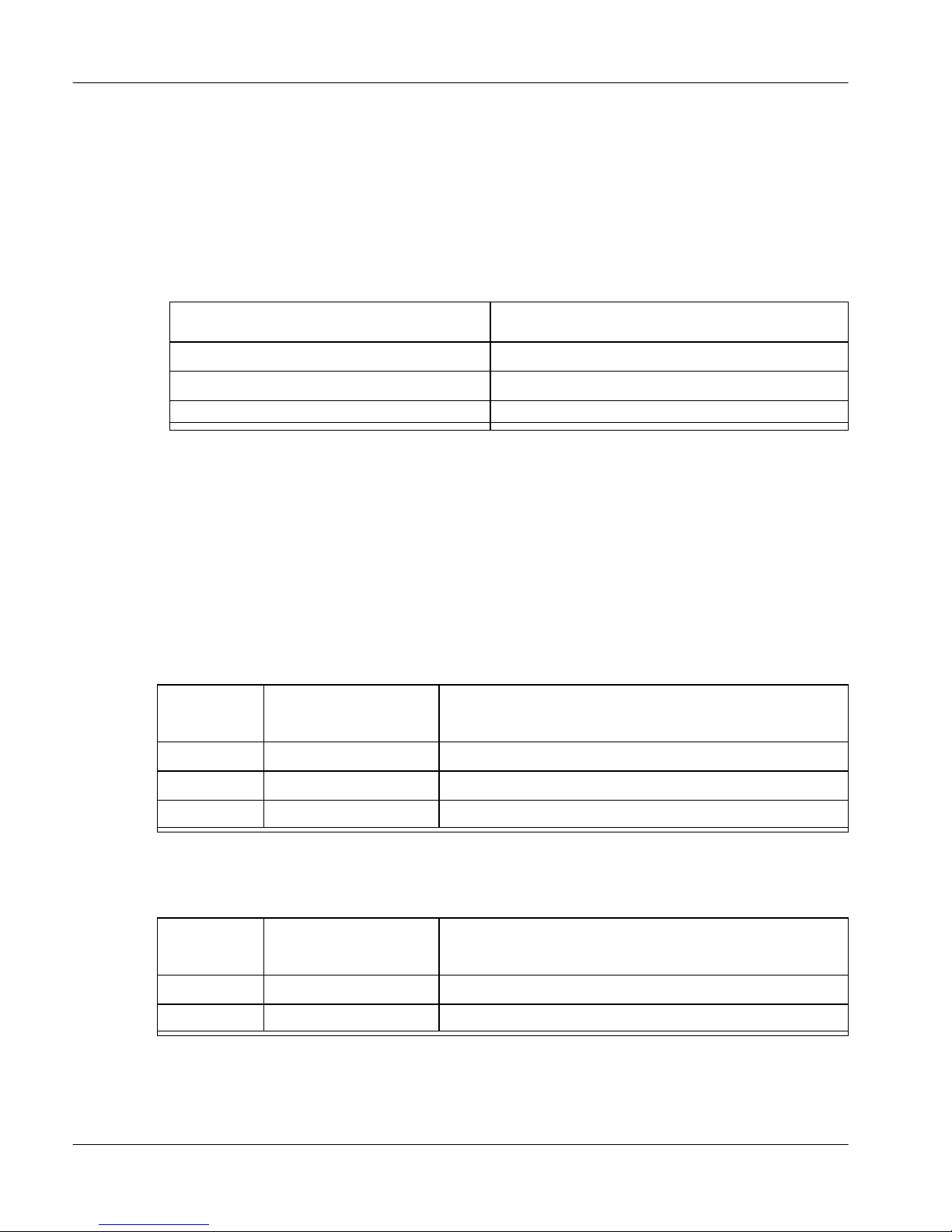
The following table calculates approximate Remote Office dial tone delay for
three different scenarios:
Remote Office
Number of appearances Call set-up duration
1 300 ms (0.30 s) 300 ms (0.30 s)
5 “ 1500 ms (1.50 s)
10 “ 3000 ms (3.00 s)
dial tone delay
Note: If you start from an idle state, include time for ISDN line set-up, which
can be as much as an additional 4–6 seconds.
Disadvantages of On Demand mode versus Permanent mode
When using the PSTN, call-establishment takes longer in On Demand mode
than in Permanent mode. This is because, in On Demand mode, the Remote
Office unit or RLC must establish a new connection for the call. In Permanent
mode, the connection already exists.
1.4.2 Release Notes for Remote Office and RLC 43
Page 44

Standard 1.1
Distinctive ring
Remote Office does not support Distinctive ring functionality of any kind.
Echo cancellation
Due to the network delay introduced by the IP network, echo is more noticeable
in VoIP networks than traditional networks. All echo cancellation algorithms
need a small amount of time to adjust if the echo path changes. This results in
the initial syllable, or word, of the first sentence having echo. After that,
however, no echo is apparent.
This is a normal characteristic of the transition point between the VoIP network
and traditional analog facilities. If echo is not cancelled after the beginning of
the first sentence, a more serious problem (such as impedance mismatch) may be
present. Also note that some environments, such as conference calls, may
change the echo path. This also results in an adjustment period for Echo
Cancellation.
Note: After investigation, Global Network Technical Support (GNTS)
discovered that the source of echo on the majority of installations is incorrectly
configured analog trunks. Please ensure that the trunks are configured correctly
in the areas of trunk card type (EXUT/XUT), TIMP, and BIMP settings, and
jumper settings on the actual trunk card itself. Also, measure the line loss and
compensate using the trunk class of service NTC or TRC as required.
Nortel Networks recommends that the trunk card be an enhanced version
(EXUT). An EXUT supports more complex impedance situations. Please refer
to NTP 553-3001-106 for trunk cards and the NTP for your specific PBX for
more information. Also, if you are connecting recording equipment or Recorded
Announcement (RAN) devices to an analog trunk, ensure that the trunk
impedance matches the equipment impedance to ensure that echo does not
occur.
44 1.4.2 Release Notes for Remote Office and RLC
Page 45

December 2003
Emergency service programmability
To access the new Emergency Activation Code dialog box, click on the
Emergency Feature button, available on both the 9150 System Configuration or
911x System Configuration property sheets. The particular emergency activation
code dialed by the user determines the digits sent to the host PBX and the
telephone number sent to the Central Office (CO).
Note: If you must contact emergency personnel with consecutive calls, you must
press the digits of the Emergency Access Code each time. Do not use last
number redial or the autodial keys.
Fax transmissions during Quality of Service transitions
If a QoS transition occurs while a Remote Office unit sends or receives a fax, the
packets lost prior to the transition can result in:
a fax that is not readable at the receiving end
!
error messages that appear on both the sending and receiving fax machines
!
If this occurs, send the fax again.
Firmware downgrades for M39xx series digital telephone sets
If you downgrade the host PBX to a release prior to X11 Release 25.40, you
must also downgrade any new or upgraded M39xx digital telephone sets so that
the Meridian 1 can support them. This applies to digital telephone sets attached
to Remote Office units and Extended Digital Line Cards.
Firmware upload and download problems with M3904 and M3905
digital telephone sets
Uploading and downloading M3904 and M3905 firmware requires the most
recent digital telephone set hardware. To resolve problems following firmware
uploads and downloads, including missing functionality, refer to the User Guide
and Release Notes for your particular digital telephone set.
1.4.2 Release Notes for Remote Office and RLC 45
Page 46

Standard 1.1
Flash upgrade downloads for M39xx series digital telephone sets
Over an IP network with low delay and packet loss, Flash upgrade download
times to remote M39xx digital telephone sets are comparable to PBX wired
downloads. Using PSTN bandwidth on a Remote Office 9150 unit or a Remote
Office 911x series unit, download times increase.
Idle set display message does not get updated
When you update the message on the host PBX that displays when the digital
telephone set is idle, you must unplug the digital telephone set and plug it back
for the change to take effect.
Inconsistent configuration of BRI speed (56K/64K) does not try 64K if
56K fails
You must configure the same BRI speed (such as 56K, 64K, or dynamic) on both
the RLC and the Remote Office 9150 unit.
Key labels for Local Keys on M3902 digital telephone sets
To label the Local Keys on M3902 digital telephone sets, use the options key on
the digital telephone set itself.
Local switchover
Proper function of local switchover requires you to enable DN Discovery. In
addition, local switchover does not function when using the Redial key or on
Call Forward.
M2616CT cordless digital telephone sets are not supported by
Remote Office 9150 units
Remote Office does not support M2616CT cordless digital telephone sets, as
M2616CT is a discontinued model.
46 1.4.2 Release Notes for Remote Office and RLC
Page 47

December 2003
M3904 Key Map fails on Virtual Office/Remote Office
The M3904 digital telephone set Key Map fails using Virtual Office on Remote
Office. Upgrade the digital telephone set’s firmware to version 7.9 to resolve
this problem.
M3905 digital telephone set logon takes longer than expected
When logging on to an ACD queue using an M3905 digital telephone set
connected to a Remote Office 9150 unit, the logon process takes longer than
expected if a headset is not plugged into the digital telephone set. Initialization
of the digital telephone set under these conditions can take up to one minute.
NAT routers
Translation tables within NAT routers control the communication path from the
private network to the public network. Most NAT devices contain a timer that
monitors the translation table entries. Each time a translation table entry is used,
the timer restarts. Individual table entries are deleted if the communications path
is not used and the timer expires.
It is possible, when using a Remote Office 9150 or 911x unit behind a NAT
device, that prolonged periods of silence cause the NAT translation table entries
to clear and drop the audio path. An example of this situation would be a remote
user listening to a conference call with their digital telephone set on mute. After
five minutes (the default NAT translation table timer on many NAT routers) the
remote user would not be able to hear the conference. The remote user can
recover the audio path by going off mute and speaking into the digital telephone
set to restore the NAT table entry.
To prevent the NAT translation table from dropping the audio path:
configure the translation tables on the NAT router with a large timer value
!
(for example, two hours)
configure a static translation table entry for UDP port 20480
!
1.4.2 Release Notes for Remote Office and RLC 47
Page 48

Standard 1.1
Phase I M3905 digital telephone sets can lock up during Remote
Office 9150 unit re-boot
Phase I M3905 digital telephone sets receive false messages during a re-boot of
the Remote Office 9150 unit and can lock up. Unplug and re-plug the telephone
cord at the wall jack or perform a system shutdown and re-power up the Remote
Office 9150 unit to recover. This is not a problem with Phase III M3905 digital
telephone sets.
PSTN connectivity test does not check the primary connection in
both directions
When performing a PSTN connectivity test, the test only checks the primary
ISDN connection outbound from the RLC. It does not check the primary
connection inbound to the RLC from the Remote Office 9150 unit’s BRI circuit.
The only way to verify an initial primary PSTN connection from the Remote
Office 9150 unit is to manually initialize the primary link from the Remote
Office 9150 unit. PSTN connectivity tests always use the configured Trunk
Support speed.
PSTN-only digital telephone set sets can be called with no ISDN line
present if signaling is over IP
Calls can be placed to PSTN-only sets if signaling is over IP but the ISDN is
unavailable. Eventually, Remote Office releases the call and displays a
“Bandwidth Limit” message.
Remote Office 911x series unit answers inbound line after power
failure
After a power failure, a Remote Office 911x series unit comes back online and
answers all incoming calls. To prevent the unit from staying online indefinitely
after a power outage, enter a single Offline command in the unit's Online/Offline
table for the week. Use SPRE codes to go online and offline.
48 1.4.2 Release Notes for Remote Office and RLC
Page 49

December 2003
Remote Office 911x series unit needs a re-boot after unplugging/
re- plugging telephone cord
You must re-boot a Remote Office 911x series unit after unplugging and
re-plugging its telephone cord.
Remote Office 911x series unit sometimes drops dialtone
If a user attempts a call during registration, the Remote Office 911x series unit
can drop dialtone as the digital telephone set is synchronized between the
Remote Office 911x series unit and the RLC. Wait 7-10 seconds for the system
to synchronize.
Send button versus OK button on Configuration Manager
The changes to the remote connections from all Configuration Manager property
sheets and dialog boxes are not saved when you press the OK button. However,
when you press the SEND button, only the information pertaining to the current
remote unit is sent to the RLC. Refer to the Installation and Configuration
manual for your specific Remote Office unit for further details.
Stutter dial tone
A stutter may be heard during a remote dial tone. This is a normal occurrence
and is caused by the DSP activating a dial tone relay. To eliminate stutter dial
tone, disable Dialtone Relay in the Advanced Configuration dialog box, which is
available on the RLC System Configuration Property sheet in Configuration
Manager. Refer to “Advanced Configuration for upgrades” on page 19 and
“Advanced Configuration settings” on page 65 for details.
Transferring calls from the analog port not possible
You cannot transfer a call on the analog port of a telephone set connected to a
Remote Office unit. Remote Office does not support Switch Hook flash.
1.4.2 Release Notes for Remote Office and RLC 49
Page 50

Standard 1.1
Voicemail messages and QoS transitions
It can take several seconds of sustained errors to cause a QoS transition to the
PSTN. During this time, voice quality may suffer due to errors. If a message to a
voice mailbox is being recorded during these errors, portions of the message
could be unintelligible.
When to restart a unit
Each time that you make a configuration change, perform a Save to Flash. You
must also restart the unit if Configuration Manager prompts you to do so.
Note: When you save configuration changes to Flash, the system suspends new
call processing for approximately 30 seconds. Some configuration changes do
not take effect until the unit has been re-started.
50 1.4.2 Release Notes for Remote Office and RLC
Page 51

December 2003
Issues Corrected Since 1.4.1
The following issues have been corrected since product release 1.4.1:
ACD buzz tone occurring in non-forced ACD environments
(Q00349147)
The ACD buzz tone no longer plays when Call Force is not enabled.
No audible DTMF tones sent on Local Switchover calls (Q00591233)
With Local Switchover enabled, the Remote Office system now correctly relays
DTMF tones to called local digital telephone sets.
Remote Office 911x series unit cannot be used in combination with
ISDN dial up routers (Q00667780)
The Remote Office 911x series unit can now be used in combination with ISDN
dial up routers.
Telephones connected to Remote Office 9150 unit show bandwidth
limit message and then drop calls when in QoS fallback mode
(Q00680880)
When in QoS fallback mode, digital telephone sets connected to Remote Office
9150 unit no longer report BW (bandwidth) limit messages and drop calls during
the movement of calls from IP to ISDN.
Inbound local call is ringing PBX DN as well (Q00687444)
This was a problem with a BFS key and the Call Forward (CFW) feature not
being cancelled for local calling. The Call Forward cancellation of a BFS was
not being handled correctly, leading to a continued local Call Forward affecting
the inbound trunk calls. Since DN Discovery was not enabled, the Call Forward
would go through the host PBX and back to the Remote key on the local
telephone. The cancelling of the Call Forward is now being handled correctly.
1.4.2 Release Notes for Remote Office and RLC 51
Page 52

Standard 1.1
Online/Offline entry schedule triggers incorrectly (Q00693823)
The Offline/Online entry schedule no longer triggers incorrectly.
Remote Office 9150 unit intermittently reboots (Q00724332)
The Remote Office 9150 unit no longer intermittently reboots.
Display Log reset causes restart of Remote Office 9150 unit
(Q00724646)
If the Display Log was previously cleared with a larger number of entries than at
the time of the current clearing, there were some invalid pointers being freed that
would lead to crashes in other areas of the Remote Office system. The Clear Log
function has been corrected to clear out the pointers after freeing the log
message, preventing the corruption if cleared again.
Using the Remote Office 911x series unit over PSTN with VAD
disabled can lead to bad voice quality (Q00727078)
This release contains a change that forces Voice Activity Detection (VAD) to be
enabled when the voice call is from a Remote Office 911x series unit over
PSTN.
BRI module 5 does not have BRI version number(Q00749468)
BRI version 33 for the U and S/T interfaces resolves this issue.
Remote Office 911x series unit cannot dial emergency services if the
V.32 modem must drop the modem connection first (Q00784430)
Dialing an emergency service (such as 911 in North America) is now successful
if the Remote Office 911x series unit is connected to the RLC through a V.32
modem and must drop the modem connection first.
52 1.4.2 Release Notes for Remote Office and RLC
Page 53

December 2003
Intermittent delayed dial tone on Local TCM digital telephone sets
(Q00784559)
When you configure the RLC port as Local TCM, connect a digital telephone set
directly to RLC, and go offhook, the digital telephone set no longer presents
intermittent delayed dial tone.
Remote Office 9150 unit leaks memory on BRI local calls when Alert
All DNs is configured (Q00786490)
The Remote Office 9150 unit no longer leaks memory on BRI local calls when
you configure Alert All DNs.
More Aggressive NLP should never be used in any situation
(Q00667804)
The previous NLP value used for “More Aggressive” is no longer available
through Remote Office Configuration Manager. It has been replaced with the
previous “Less Aggressive” value and a new lesser aggressive value has been
chosen to act as the “Less Aggressive” mode. Respectively, “More” is now
“Less” in this case.
1.4.2 Release Notes for Remote Office and RLC 53
Page 54

Standard 1.1
Known problems in this release
This section describes known problems with this release and suggests solutions
to these problems, if solutions are available.
M3902 digital telephone sets connected to Remote Office 9150 units
connected to Succession 1000 PBXs have display irregularities in
survivable mode (Q00352179)
When Succession 1000 PBXs go into survivable mode, M3902 digital telephone
sets connected to Remote Office 9150 units connected to these PBXs react
abnormally. These digital telephone sets temporarily present abnormal messages
in their telephone set displays.
RLC maintenance LED stays off when RLC is disabled using DISS
command in Load 32 on Succession 1000 PBXs (Q00352255)
Maintenance LEDs on RLCs installed in Succession 1000 PBXs do not respond
properly to the Load 32 (LD32) command, Disable Shelf (DISS). The LED is
off, or dark, when the RLC is operating correctly. The LED’s being on, or lit,
usually indicates that the RLC is disabled or experiencing some sort of a
problem. When the maintenance LED remains off after you enter the DISS
command, enter the Disable Card (DISC) command for that card.
DSP Limit error message does not clear from digital telephone set
displays (Q00536585)
After DSP Limit error messages appear on the displays of digital telephone sets
connected to Remote Office units, the messages do not clear. To clear the
display, press the Release (Rls on some digital telephone sets) key or lift the
handset when the error no longer exists.
54 1.4.2 Release Notes for Remote Office and RLC
Page 55

December 2003
User On Demand Idle Timer is not accurate (Q00537074)
The User On Demand Idle Timer can have an error of as much as the length of
time configured for the timer. For example, if the idle timer is configured for 90
seconds, it is possible for up to 180 seconds to pass before the link drops. In this
example, every 90 seconds the system reviews the previous 90-second period to
see if any activity took place within that period. A call can end milliseconds
after the beginning of a 90-second period. If so, when the system reviews that
90-second period, it registers activity. Therefore, the link stays up for an
additional 90 seconds. If this happens, the link is up and idle for nearly 180
seconds.
Configuration Wizard displays Error: 1250 - Invalid Command
(Q00541393)
After you re-set the configuration of a Remote Office 911x series unit, altering
the unit's configuration with the Configuration Wizard results in the following
error: 1250 - Invalid Command. After re-setting the configuration of a Remote
Office 911x series unit, you must re-enter the configuration manually.
Display logs clear when power is lost (Q00549069)
When a Remote Office unit loses power, whether through a user command or a
power outage, the display logs are re-set, deleting all stored logs.
Cannot use online SPRE code after abnormal line failure (Q00550215)
If a Remote Office 911x series unit abnormally loses its connection to the RLC,
the online SPRE code does not bring the unit back online. To reconnect the
Remote Office 911x unit to the RLC, press the primary DN key or disconnect
and then re-connect the power to the unit.
M3905 digital telephone sets do not play tone B for a second
incoming call (Q00557165)
If an M3905 digital telephone set is on a call when another call comes in, it does
not alert the user by playing tone B. The only indication that the user has of a
second incoming call is the flashing of the call indicator.
1.4.2 Release Notes for Remote Office and RLC 55
Page 56

Standard 1.1
Invalid security ID renders M3904 digital telephone sets inoperable
(Q00563257)
When a user tries to register an M3904 digital telephone set connected to a
Remote Office 9115 unit using an invalid security ID, the digital telephone set
freezes. Subsequent attempts to register that digital telephone set fail, even with
the proper security ID. You must unplug the digital telephone set and plug it
back in to get the key labels to re-appear. Sometimes you must unplug the digital
telephone set and plug it back in a second time to restore the functionality to all
the keys.
Remote call forward command causes some M3903 digital telephone
sets connected to Remote Office units to lock up (Q00569412)
M3903 digital telephone sets running 8.3 software and connected to Remote
Office units lock up in response to the Remote Call Forward (RCFW) command.
This only occurs when connected to Meridian 1 PBXs running X11 25.40B
software with patch release MPLR17012.
LD 32 command IDU shows M39xx series digital telephone set details
when telephone set no longer connected (Q00569821)
After unplugging an M39xx series digital telephone set from a Remote Office
9150 unit, an Identify Unit (IDU) command in Load 32 (LD 32) reports the
telephone set details as if the telephone set were still connected.
Hold indicator does not flash after second local call during fallback
(Q00534119)
When in fallback mode on the Remote Office 911x series unit with a remote
telephone call on hold, after placing a local call, the hold indicator does not flash
after the modem reconnects for the second time. Instead, the hold indicator
works one time for each fallback.
56 1.4.2 Release Notes for Remote Office and RLC
Page 57

December 2003
G729/Fax calls sometimes fail (Q00590727)
In Europe, faxes fail when sent from Canon L300/L350 fax machines to Toshiba
CP120F fax machines using the G729/Fax compression algorithm. This problem
does not occur when using the G.711 compression algorithm. Be aware,
however, that the G.711 compression algorithm requires more bandwidth.
No audible DTMF tones sent on Local Switchover calls (Q00591233)
With Local Switchover enabled, the Remote Office system does not relay
DTMF tones to called local digital telephone sets. To relay DTMF tones on local
calls, you must either disable Local Switchover or use speed dial to send the
desired digits.
Midnight routines cause signaling link to connect (Q00595075)
The Remote Office system establishes a signaling link when it runs midnight
routines. To avoid this, program an offline period in the online/offline table for
the time that the midnight routine is scheduled to run.
Remote Office 911x series unit telephone set menu allows CIDR
configuration (Q00609432)
The Remote Office family of products does not support Classless Inter-Domain
Routing (CIDR), that is, a Class C address with a Class B mask. However, the
Remote Office 911x series unit telephone set menu, or telephone set user
interface (TUI), allows CIDR configuration. CIDR configuration causes a
Remote Office 911x series unit to perpetually re-boot. If you program a CIDR
configuration on your Remote Office 911x series unit, you must send the unit
back to the manufacturer for restoration.
Remote Office PINGs report inaccurate response times when
network-induced round-trip delay is over 200 ms (Q00611480)
When conducting PING tests between Remote Office units, it is possible to
receive incorrect response times if the IP network induces round trip delay of
over 200 ms.
1.4.2 Release Notes for Remote Office and RLC 57
Page 58

Standard 1.1
Remote Office 911x series units only dial 20 digits pulled from the
PSTN Number to Connect to RLC field (Q00615074)
Remote Office Configuration Manager allows administrators to configure up to
30 digits in the PSTN Number to Connect to RLC field. However, the Remote
Office 911x series units only dial the first 20 digits in this field when trying to
establish a connection to the RLC.
BRI-S module sometimes locks up after the physical connection
drops (Q00628415)
If the physical connection between the Remote Office 9150 unit and RLC drops
while the signaling link is still up, the BRI module can lock up. This happens if
the physical connection does not re-establish before the User On Demand Idle
timer expires.
After reboot of Remote Office 9150 unit, ATA port does not work
(Q00659815)
After reboot of a Remote Office 9150 unit, the ATA port does not work. As a
work around, reboot each ATA as well.
Comfort noise does not accurately track background noise
(Q00666182)
The Remote Office product does generate comfort noise, but at a fixed level.
This issue can cause noise pumping to occur. When the “silent” party starts
speaking again, the noise floor can change and it can be noticeable. You can
avoid this by disabling VAD.
Display Log number 93 is not always logged (Q00688016)
Display Log number 93 is not logged when dialing from the local key. This log
indicates that the Emergency Access Code (EAC) has been dialed from a port.
When an Emergency number is dialed using the local key, it does not display in
the Display Logs.
58 1.4.2 Release Notes for Remote Office and RLC
Page 59

December 2003
Multiple sets with Call Forward on local BRI inbound call are not
treated correctly (Q00699973)
When placing two or more digital telephone sets in DN's to Alert Trunk Group
mode and placing two or more of these same digital telephone sets in Call
Forward to a PBX DN mode, multiple digital telephone sets with Call Forward
on a local BRI inbound telephone call are not treated correctly. The single
incoming BRI telephone call gets answered and does not terminate the second or
more Call Forward telephone call.
Remote Office 9150 unit’s inbound local call rings all digital telephone
sets when no trunk group is enabled to do so (Q00787132)
When no trunk groups are enabled, and you select either Local or Local and
Remote configuration on the B-channel, an incoming telephone call rings all
digital telephone sets connected to the Remote Office 9150 unit.
BRI module configuration rules are not observed on inbound local
calls (Q00787134)
The Trunk Group configurations for the Remote Office 9150 unit are used to
determine how inbound and outbound local calls over the BRI should be
managed. The BRI module configuration is not strictly observed by incoming
calls when the BRI module configurations for channels B1 and B2 are not set to
the same mode.
Emergency 911 can be dialed during certain call scenarios
(Q00789098)
The Remote Office 9150 and Remote Office 911x series units track when 911 is
actually dialed. The following example explains a scenario where emergency
911 can be dial.
When an agent receives an incoming ACD call and the agent accepts the call but
the agent determines that the call is not for their group. The agent presses the
Conference key. Then the agent presses a non-digit key such as the Speed Call
key. The agent enters “91” and the telephone call goes out to the entry in list 91.
The agent hears an IVR and enters “1” to select English.
1.4.2 Release Notes for Remote Office and RLC 59
Page 60

Standard 1.1
When any non-digit key (such as Account, Speed Dial, Make Set Busy) is
pressed after the Conference key is pressed, the units can get confused and dial
emergency 911. As a work around to avoid this situation, remove speed call list
91.
Signaling link is lost on a normal closure over PSTN after a QoS
transition (Q00795992)
When you configure signaling for Permanent mode over IP and On-demand
mode over PSTN, the RLC generates an abnormal failure over PSTN after being
cleared normally due to an Idle condition detected. If after the QoS transition
occurs, additional B-channels are established, the problem does not occur.
PSTN connection can stay established if a failure on IP causes QoS
with no call activity (Q00796080)
A PSTN connection can stay established if a failure on IP causes QoS with no
call activity. This issue only occurs when you configure signaling for Permanent
mode over IP and On-demand mode over PSTN. In this mode, if the IP
connection fails, the system transitions over to PSTN. If the IP connection then
recovers before the PSTN Idle Timer expires, the PSTN connection continues
permanently until the system performs a QoS recovery.
Remote Office 9150 Bridge Ports flag is not clearing when changed local calls do not transfer (Q00796821)
If you configure a port as “Local & Remote” with Bridge Ports Enabled and then
change the configuration to either “Local” or “Remote” mode, the Bridge Port
Enabled field still exists in the database. The Remote Office system continues to
try and use this port as a Bridge Port causing problems with local call transfers.
To prevent this from happening, disable the Bridge Port field, perform a Save to
Flash, and then change the mode to “Local” or “Remote” and again perform a
Save to Flash.
60 1.4.2 Release Notes for Remote Office and RLC
Page 61

December 2003
Documentation additions and corrections
This section provides corrections for known omissions and mis-statements in the
Remote Office documentation.
G.729A voice compression
Previous versions of Remote Office documentation and the Remote Office Help
application sometimes refer to the G.729 voice compression algorithm. The
Remote Office family uses the G.729A version of this algorithm. The current
version of the Remote Office Help application reflects this correction. Any
information referring to the G.729 voice compression algorithm in Remote
Office documentation actually concerns G.729A. This applies to both the Reach
Line Card Installation and Administration Guide (NTP 555-8421-210) and the
Remote Office 9150 Installation and Administration Guide (NTP
555-8421-215). In both Guides, replace references to G.729 with G.729A.
Ethernet connection
On page 2 of the Reach Line Card Installation and Administration Guide
(NTP 555-8421-210), it states:
You can configure each port on the RLC as if telephones were
locally connected to a standard XDLC. Existing digital trunks
(PRI) or an integrated 10BaseT Ethernet interface (Voice over IP)
carry voice and signaling traffic as packets.
This is correct, but incomplete. This paragraph should conclude with the
following note:
Note: The RLC defaults to a half-duplex 10BaseT Ethernet
connection. You can configure a full-duplex 10BaseT Ethernet
connection through Configuration Manager. When you configure
a full-duplex 10BaseT Ethernet connection, the RLC's Ethernet
collision LED remains on solid (constantly lit). This does not
indicate collisions on the segment, but that Full duplex is enabled.
1.4.2 Release Notes for Remote Office and RLC 61
Page 62

Standard 1.1
On page 9 of the Remote Office 9150 Installation and Administration Guide
(NTP 555-8421-215), the 10BaseT Ethernet and ISDN BRI connections
paragraph should conclude with the following note:
In addition, when you enable full-duplex Ethernet, you must also
set the corresponding port on the connected switch to 10 FULL
Duplex. Remote Office products do not support Auto negotiation
of the Ethernet interface.
Note: The Remote Office 9150 unit, vintages AC, BC, CC, and earlier use a
half-duplex 10BaseT Ethernet connection. Vintages AD, BD, CD and later
default to a half-duplex 10BaseT Ethernet connection. You can configure a
full-duplex 10BaseT Ethernet connection on units of these vintages through
Configuration Manager. When you configure a full-duplex 10BaseT
Ethernet connection, the Remote Office 9150 unit's Ethernet collision LED
remains on solid (constantly lit). In addition, when you enable full-duplex
Ethernet, you must also set the corresponding port on the connected switch
to 10 FULL Duplex. Remote Office products do not support Auto
negotiation of the Ethernet interface.
On page 17 of the Remote Office 9150 Installation and Administration Guide
(555-8421-215), the 10BaseT Ethernet interface paragraph should conclude with
the following note:
Note: You can configure the Remote Office 9150 unit to use
either a half- or full-duplex 10BaseT Ethernet connection through
Configuration Manager.
On page 11 of the Remote Office 911x Series Installation and Administration
Guide (NTP 555-8421-220), the 10BaseT Ethernet interface paragraph should
conclude with the following note:
Note: The Remote Office 911x series unit uses a half-duplex
10BaseT Ethernet connection.
On page 11 of the Meridian Digital Telephone IP Adapter Installation and
Administration Guide (NTP 555-8421-211), the 10BaseT Ethernet interface
paragraph should conclude with the following note:
Note: The Meridian Digital Telephone IP Adapter unit uses a
half-duplex 10BaseT Ethernet connection.
62 1.4.2 Release Notes for Remote Office and RLC
Page 63

December 2003
9150 support on RLCs
On pages 2, 14, 107, and 178 of the Reach Line Card Installation and
Administration Guide (NTP 555-8421-210), it states that a single RLC supports
a maximum of four Remote Office 9150 units. This release enables a single RLC
to support a maximum of eight Remote Office 9150 units.
Supported telephone models
On page 23 of the Reach Line Card Installation and Administration Guide (NTP
555-8421-210), note ii states, “On the host PBX, you must configure M3901
digital telephone sets as M3902 digital telephone sets for proper operation with
Remote Office 911x series units or Meridian Digital Telephone IP Adapters”.
Disregard this note. The correct information is as follows:
M3901 digital telephone set support
Remote Office allows you to use M3901 digital telephone sets for
local (locally controlled) calls or for remote (host-controlled)
calls, not both. For local (locally controlled) calls, configure the
digital telephone set as an M3901 at both the remote unit and the
host PBX. For remote (host-controlled) calls, configure the
digital telephone set as an M3901 at the remote unit and as an
M3902 at the host PBX.
Advanced Configuration
Page 149 of the Reach Line Card Installation and Administration Guide
(NTP 555-8421-210) includes the explanation of the RLC System Configuration
property sheet. This property sheet contains a new button called “Advanced
Configuration”. Below is a discussion of the elements of the Advanced
Configuration dialog box.
NLP
The non-linear processor (NLP) works with the Remote Office echo canceller to
reduce echo. Echo occurs in a telephone call when the transmitted signal reflects
and is received by the transmitting device. To cancel the echo, the Remote
Office system monitors the audio stream looking for echo. When echo is
1.4.2 Release Notes for Remote Office and RLC 63
Page 64

Standard 1.1
identified it is digitally (mathematically) removed. If the echo is very strong, a
small amount of echo may remain called "residual" echo. The aggressiveness of
the NLP determines how quickly and how effectively the Remote Office NLP
reduces the residual echo.
The operation of the NLP can affect how the audio sounds during double-talk
situations - when both parties are speaking. Cultural differences also changes
how often double-talk occurs during a conversation.
Nortel Networks recommends the following settings as a starting point:
!
!
If the Remote Office 9150 unit user hears echo during conversations, adjust the
settings, as follows:
!
RLC: NLP Enabled - Less Aggressive (default)
9150: NLP Enabled - More Aggressive (default)
RLC: NLP Enabled - More Aggressive
9150: NLP Enabled - Less Aggressive
!
If the party on the PBX side hears echo during conversations, adjust the settings,
as follows:
RLC: NLP Enabled - More Aggressive
!
9150: NLP Enabled - More Aggressive
!
The NLP does not have to operate aggressively if echo is not present. If echo is
not present but double-talk is present, even with Less Aggressive settings, try
disabling the NLP on the RLC.
Dialtone/DTMF Relay
Dialtone/DTMF Relay allows you to manage the bandwidth used by your
Remote Office units for generating dial tone and Dual Tone Multi-Frequency
(DTMF), or button-press, tones. With Dialtone/DTMF Relay enabled, Remote
Office units send encoded data packets to the other side when they detect either
dial tone or DTMF tones. With Dialtone/DTMF Relay disabled, the units send
voice packets to the other side when they detect a dial tone or DTMF tones. The
former method uses less bandwidth, but produces rougher DTMF tones and a
dial tone that begins with an audible click. The latter method produces smoother
DTMF tones and dial tone, but uses more bandwidth.
64 1.4.2 Release Notes for Remote Office and RLC
Page 65

December 2003
Advanced Configuration settings
Click on the Advanced configuration button to access the Advanced
Configuration dialog box. This dialog box provides access to the following
fields:
Field Description
NLP (Non-Linear
Processing)
Dialtone/DTMF
Relay
Refer to “NLP” on page 63 for information on the proper
configuration of these settings.
! Click on the Enable option button to instruct the RLC and
its remote units to send the dial tone and DTMF tones as
data packets.
! Click on the Disable option button to instruct the RLC and
its remote units to send the dial tone and DTMF tones as
voice packets.
The default is Enable.
RLC Extension to Dial field descriptions
On page 154 of the Reach Line Card Installation and Administration Guide
(NTP 555-8421-210), incorrect field descriptions appear for part of the RLC
System Configuration property sheet. The correct field descriptions are as
follows:
RLC Extension to Dial Use these fields to configure the port number, feature
key position, and DN of the RLC extension to be used for DN Discovery. At the
time configured for DN discovery, each remote port on the RLC places a call to
the extension described by these fields. The RLC assigns the incoming Calling
Line Identification (CLID) name and number to the calling port:
Port–This field identifies the port called for DN discovery.
!
Feature Key–This field identifies the feature key configured on the host
!
PBX for the port called for DN discovery.
DN–This field identifies the DN assigned to the feature key and port called
!
for DN discovery.
1.4.2 Release Notes for Remote Office and RLC 65
Page 66

Standard 1.1
Full-duplex Ethernet support
On page 160 of the Reach Line Card Installation and Administration Guide
(NTP 555-8421-210), the field descriptions for the RLC IP Configuration
property sheet are listed. Page 195 of the Remote Office 9150 Installation and
Administration Guide (NTP 555-8421-215) describes configuring the 9150 IP
Configuration property sheet. Both of these property sheets now provide fields
that allow you to configure Full-duplex Ethernet support for the Remote Office
IP interface. The following table explains the Full-duplex Ethernet setting:
Field Description
Full Duplex Ethernet
! Click on the Enable option button if
you want the network Ethernet port
to be able to simultaneously transmit
and receive Ethernet packets at any
given time (full duplex).
! Click on the Disable option button if
you want the network Ethernet port
to be able to only send or receive
Ethernet packets at any given time
(half duplex).
66 1.4.2 Release Notes for Remote Office and RLC
Page 67

December 2003
Bandwidth usage during QoS transitions
On page 164 of the Reach Line Card Installation and Administration Guide
(NTP 555-8421-210), the procedure for configuring a remote port on an RLC
appears. The Remote Port Configuration dialog box, which is described there,
has a new field for controlling bandwidth usage during a QoS Transition.
Refer to the following table for an explanation this field:
Field Description
G729 During QoS Transition
Note: Click on the Disable option button in this field if the system or port is
configured as PSTN only. If you do not disable this option, the system does not
allow PSTN-only ports to use compression algorithms other than G.729A.
Modem options
On page 174 of the Reach Line Card Installation and Administration Guide
(NTP 555-8421-210), the description of the PSTN configuration fields begins.
This area of the Remote Connection Configuration property sheet contains a
new button, Modem Options. This setting helps minimize the time required to
establish a modem connection when using the Remote Office 911x series unit
with an on-demand allocation over the PSTN. Click this button to access a
dialog box where you configure the length of the answer tone on the answering
modem when establishing a connection between an RLC and a Remote Office
911x unit. The answer tone disables echo cancellers on long distance calls so
that modem training is not disrupted.
! Click on the Enable option button if
you want to allow the RLC and the
9150 unit to change configured
G.711 or G.726 compression
algorithms during QoS transitions on
this port.
! Click on the Disable option button if
you do not want to allow
compression algorithm changes
during QoS transitions on this port.
Note: The answer tone length represents a portion of the total time required for
the 911x and RLC to call, train and establish a connection.
1.4.2 Release Notes for Remote Office and RLC 67
Page 68

Standard 1.1
V32 Answer Tone Duration
The RLC passes this setting to the Remote Office 911x series unit when it
connects for the first time. For subsequent calls, the Remote Office 911x series
unit answers the modem with an answer tone of the correct duration.
Move the slider to the desired length of the answer tone on the receiving modem
according to the guidelines in the following table.
Note: This table is only a guide. Your individual situation (exact length of your
connections, long distance carrier, and so on) dictates the specific setting that
you need to configure. Start with the default setting and test from there. If the
connection does not establish, try configuring a longer answer tone by moving
the slider farther to the right
Min (Local Calls Only) Move the slider toward this setting if the RLC and
Setting Explanation
Remote Office 911x series unit are local to one
another.
Avg (Long Distance) This is the default setting. Move the slider closer
Max (Very Long/International) Move the slider toward this setting if the RLC and
DSP Load configuration
On page 196 of the Reach Line Card Installation and Administration Guide
(NTP 555-8421-210), the field description for the DSP Load drop-down list
shows the valid options as G729A, 911X, and AUTO. This release adds
G723_CONF to this list. G723_CONF allows you to record telephone calls
using IDVR. For more information regarding IDVR, contact your TelStrat
representative.
to this setting for long distance calls within the
same country.
Remote Office 911x series unit are very far apart,
or in different countries.
68 1.4.2 Release Notes for Remote Office and RLC
Page 69

December 2003
Ethernet Interface Statistics field descriptions
Page 235 of the Reach Line Card Installation and Administration Guide
(NTP 555-8421-210), page 293 of the Remote Office 9150 Installation and
Administration Guide (NTP 555-8421-215), page 157 of the Remote Office 911x
Installation and Administration Guide (NTP 555-8421-220), and page 134 of
the Meridian Digital Telephone IP Adapter Installation and Administration
Guide (NTP 555-8421-211), include the Ethernet Interface Statistics field
descriptions. The following statistics have been identified more clearly:
“IN - Octet” is now “Rx - Octet
!
“OUT - Octet” is now “Tx - Octet”
!
Collisions
Half-duplex Ethernet connections only allow their nodes to either send or
receive packets at any given time. Collisions occur when two nodes on a
half-duplex Ethernet connection attempt to transmit information simultaneously.
Before transmitting, the Network Interface Card (commonly referred to as the
NIC card) monitors the line, or listens, for transmissions. A NIC card listens to
the line for the amount of time that it takes to transfer a minimum-sized packet
the maximum length of the cable. If the NIC card senses no transmission from
the destination node, it proceeds with its own transmission.
If a NIC card detects a collision, it waits for a period of time determined by the
back-off algorithm, then re-transmits the packet. Ethernet nodes keep track of
how many times they must re-transmit a packet with a maximum collision re-try
counter. In previous versions of Remote Office, the maximum collision re-try
counter had a limit of 15. After 16 unsuccessful attempts to transmit a packet
(the original attempt plus 15 re-tries) the Remote Office unit dropped the packet.
In an effort to decrease delay and improve QoS, the limit of the maximum
collision re-try counter is now eight. After nine unsuccessful attempts to
transmit a packet (the original attempt plus eight re-tries) the Remote Office unit
drops the packet and begins attempting to transmit the next packet.
1.4.2 Release Notes for Remote Office and RLC 69
Page 70

Standard 1.1
To help you monitor QoS on your half-duplex Ethernet connection, Remote
Office now adds a new statistic, Collisions, to Configuration Manager. The
collision statistic tracks how many times it is necessary to back off and
re-transmit a packet. It is normal for this statistic to be greater than zero on busy
networks. However, an excessive number of collisions indicates a possible
network overload.The Collisions statistic is defined as follows:
Collisions This statistic identifies the number of collisions that have occurred
Note: The Collisions statistic appears on both the Ethernet Interface and
Network Statistics screens. It is only applicable in half-duplex mode, as
explained under “Full-duplex Ethernet support” on page 66.
Statistic Description
on the Ethernet interface while attempting to transmit packets
since the statistics were last re-set.
70 1.4.2 Release Notes for Remote Office and RLC
Page 71

December 2003
Network Statistics information
On page 241 of the Reach Line Card Installation and Administration Guide
(NTP 555-8421-210), page 306 of the Remote Office 9150 Installation and
Administration Guide (NTP 555-8421-215), page 161 of the Remote Office 911x
Series Installation and Administration Guide (NTP 555-8421-220), and page
138 of the Meridian Digital Telephone IP Adapter Installation and
Administration Guide (NTP 555-8421-211), the Network Statistics and
associated field descriptions have been enhanced to include more detail as
follows:
Note: A decoder packet is a nominal DSP voice packet. The size of a decoder
packet varies according to the compression algorithm used. Decoder packets can
be added to a superpacket before the DSP forwards the superpacket to the host.
Field Description
Hour This statistic identifies the 60-minute period, within the most recent
24 hours, to which the other statistics on this line apply.
The statistics on the line where "0" is in this column refer to activity
that occurred within 60 minutes of the request for statistics. The
statistics on the line where "1" is in this column refer to activity that
occurred during the 60-minute period that ended 60 minutes, or one
hour, before the request for statistics. The statistics on the line where
"2" is in this column refer to activity that occurred during the
60-minute period that ended two hours before the request for
statistics, and so on.
Tx Voice
Samples
Rx Voice
Samples
Rx Error This statistic identifies the number of decoder packet overruns and
1.4.2 Release Notes for Remote Office and RLC 71
This statistic identifies the number of decoder packets transmitted by
the DSP during the given hour. This number corresponds to in-band
signaling, such as DTMF or Fax Relay, and voice signaling
transmitted by the DSP.
Note: This statistic formerly was expressed in superpackets rather
than decoder packets.
This statistic identifies the number of decoder packets received by
the DSP during the given hour. This number corresponds to in-band
signaling, such as DTMF or Fax Relay, and voice signaling received
by the DSP.
Note: This statistic formerly was expressed in superpackets rather
than decoder packets.
underruns during the given hour, as determined by the DSP.
Page 72

Standard 1.1
Rx Dropped This statistic identifies the number of superpackets that were
%Error This statistic identifies the packet error percentage that was received
EthTx Mcast This statistic identifies the number of multicast packets transmitted
Field Description
received out of sequence during the given hour.
This can result from one or more superpacket's being lost or
delivered out of order and, thus, discarded.
during the given hour.
Remote Office begins calculating this statistic by adding the number
out-of-sequence packets (Rx Dropped) to the number of overruns.
After multiplying this sum by 100, Remote Office then divides the
product by the number of received decoder packets (Rx Voice
Samples) to produce the error percentage.
This is an imprecise measurement due to the fact that multiple
packet losses or overruns can be counted as a single error.
during the given hour.
Multicast packets are packets intended for multiple Ethernet
addresses.
EthTX Ucast This statistic identifies the number of unicast packets transmitted
during the given hour.
Unicast packets are packets intended for a specific Ethernet
address. Voice packets are always transmitted as unicast packets.
EthTx Disc This statistic identifies the number of packets discarded on the
transmit side due to lack of resources, such as memory buffers,
during the given hour.
This can be an indirect result of excessive collisions in the transmit
queue.
EthTx Err This statistic identifies the number of packets that could not be
transmitted because of errors within the packets.
EthRx Mcast This statistic identifies the number of multicast packets that were
received during the given hour. This is inclusive of packets with
broadcast MAC addresses for protocols such as ARP, and multicast
packets for group-oriented transmissions, such as IP Multicast.
Multicast packets are packets intended for more than one Ethernet
address.
EthRx UCast This statistic identifies the number of unicast packets that were
received during the given hour with a unicast Ethernet address
directly matching that of the specified unit.
Unicast packets are packets intended for only one Ethernet address.
72 1.4.2 Release Notes for Remote Office and RLC
Page 73

December 2003
Field Description
EthRx Disc This statistic identifies the number of packets that were received
EthRx Err This statistic identifies the number of packets that were received
Collisions This statistic identifies the number of collisions that have occurred on
DSP allocation
Pages 293–296 of the Reach Line Card Installation and Administration Guide
(NTP 555-8421-210) explain how to calculate DSP module allocation for the
RLC. This section is missing instructions for determining the effect of fax calls
on DSP usage in a Remote Office system. In addition, page 357 of the Remote
Office 9150 Installation and Administration Guide (NTP 555-8421-215)
explains the same calculation for the Remote Office 9150 unit. The information
for determining the effect of fax calls on the Remote Office 9150 unit’s DSP
usage is incorrect.
during the given hour and discarded due to a lack of available
receive buffers.
during the given hour that contained errors that prevented them from
being deliverable to a higher-layer protocol.
the Ethernet interface when attempting to transmit packets since the
statistics were last re-set.
Complete the procedure below to determine the total number of DSP
Application modules required by fax calls in your system before completing the
procedures that appear in the guides:
Calculating DSP usage for fax calls in Remote Office systems
How many simultaneous faxes do you want your equipment to support?
1 Multiply the number of simultaneous faxes by two to determine the total
number of DSP channels required for fax calls. (Each fax call requires two
DSP channels.)
Step 1: _______ x 2 = _______
Notes:
a. If the number of DSP channels required for fax calls is not divisible by
four, round up the number entered in step 1 to the next multiple of four.
(Each DSP device contains four channels.)
b. Always round up to a higher number.
1.4.2 Release Notes for Remote Office and RLC 73
Page 74

Standard 1.1
2 Divide the total number of DSP channels required for fax calls by four to
3 For RLCs, add the answer obtained in step 2, above, to the final answer
On page 294 of the Reach Line Card Installation and Administration Guide
(NTP 555-8421-210), step A is incomplete. The complete step reads as follows:
(simultaneously ringing or active voice channels for 9150 and 911x) / 4
On page 295 of the Reach Line Card Installation and Administration Guide
(NTP 555-8421-210), step 7 is a duplicate of step 10. Disregard step 7.
determine the number of DSP devices required for fax calls. (Configuration
Manager assigns DSP function on a per-device basis.)
Step 2: _______ / 4 = _______
obtained in step 4 on page 295 of the Reach Line Card Installation and
Administration Guide (NTP 555-8421-210).
A: voice DSP devices required =
On page 355 of the Remote Office 9150 Installation and Administration Guide
(NTP 555-8421-215), Line 6 should say, “If line 5 is Yes, add 2 to line 4.” Add
the number of DSP devices required for fax calls, determined in the revised step
2, above, to the answer for Line 17 on page 357 of the 9150 Guide, and continue
with Line 18 in the 9150 Guide.
74 1.4.2 Release Notes for Remote Office and RLC
Page 75

December 2003
Supported digital telephone sets on Remote Office 9150 units
Page 35 of the Remote Office 9150 Installation and Administration Guide
(NTP 555-8421-215) presents a list of the digital telephone sets supported on the
Remote Office 9150 unit. This list should now include the M3901 digital
telephone set. The first two notes that follow this list should be revised to read as
follows:
Notes:
!
!
M39xx Call Log
Page 35 of the Remote Office 9150 Installation and Administration Guide
(NTP 555-8421-215) includes a note stating “You cannot dial directly from the
Call Log of M39xx series telephones because the Trunk Access code and
country code may not be displayed”. This note is incorrect. The corrected note is
the third note after the Supported digital telephone list and reads as follows:
!
If you want to use an M3901 digital telephone set for remote
(host-controlled) calls, you must configure the digital telephone
set as an M3901 at the remote unit and as an M3902 at the host
PBX. For local calls, you must configure the M3901 digital
telephone set as an M3901 at both the remote unit and the host
PBX.
The M2006 digital telephone set is also supported, but can
be used only for locally controlled calls.
You cannot dial host PBX calls from the Call Log of M39xx
series digital telephone sets because the Trunk Access code
and country code can be not displayed. You cannot dial
local calls from the Call Log of the M39xx series digital
telephone sets because the information contained in the Call
Log does not contain trunk group information.
1.4.2 Release Notes for Remote Office and RLC 75
Page 76

Standard 1.1
Fax support
Any Remote Office Guide that discusses configuring data capability for PBX
ports associated with fax calls is incorrect. In all cases, you must configure voice
capability on PBX ports associated with fax calls.
Page 47 of the Remote Office 9150 Installation and Administration Guide
(NTP 555-8421-215) includes the following sentence:
Faxes are sent uncompressed (that is, you require 64 Kbps of
bandwidth).
Disregard this sentence. It is incorrect.
Page 82 of the Remote Office 9150 Installation and Administration Guide
(NTP 555-8421-215) includes instructions for “Port and station assignment”.
The first paragraph is missing the following concluding sentence:
This includes the analog port and the stations using ATAs.
Page 82 of the Remote Office 9150 Installation and Administration Guide
(NTP 555-8421-215) includes the following statement:
Exception: You must assign the fax machine and stations that use
ATAs or MCAs for data transmission to ports that are configured
on the host PBX with data capability.
This statement is incorrect. The correct statement reads as follows:
Exception:.You must assign stations that use MCAs for data
transmission to ports that are configured on the host PBX with
data capability.
Page 224 of the Remote Office 9150 Installation and Administration Guide
(NTP 555-8421-215) provides a table that includes the following sentence:
“If G.729/Fax or G.711 compression is being used and the call is
a fax call, then the fax call is sent as 64 Kbps”.
This statement is incorrect. The correct information is as follows:
!
If using G.729/Fax and the call is a fax call, then the fax call
is sent as 9600 bps.
76 1.4.2 Release Notes for Remote Office and RLC
Page 77

December 2003
!
If using G.711 (uncompressed) and the call is a fax call,
then the fax call is sent as 64 Kbps.
To implement a Remote Office 9150 unit behind a NAT router
Page 85 of the Remote Office 9150 Installation and Administration Guide
(NTP 555-8421-215) describes how to implement a Remote Office 9150 unit
behind a NAT router. There are several references to a “PNAT router” that
should read “NAPT router”. A NAPT router is a Network Address and Port
Translation router.
What to do if the telephone connection tests do not work
On page 140 and 141 of the Remote Office 9150 Installation and Administration
Guide (NTP 555-8421-215) the section titled “What to do if the telephone
connection tests do not work” does not include step 7. Step 7 should read as
follows:
7 Use Configuration Manager to examine the display logs for errors.
Note: Refer to the Configuration Manager Help application for a
complete listing of all display logs and the condition indicated by
each.
Non-Linear Processing
Page 186 of the Remote Office 9150 Installation and Administration Guide
(NTP 555-8421-215) begins the 9150 System Configuration field descriptions.
This release adds the NLP field so that you can alter Non-Linear Processor
(NLP) settings.
Refer to “NLP” on page 63 for a full discussion of non-linear processor settings
for both the Remote Office 9150 unit and the RLC.
1.4.2 Release Notes for Remote Office and RLC 77
Page 78

Standard 1.1
Companding Algorithm
On page 189 of the Remote Office 9150 Installation and Administration Guide
(NTP 555-8421-215), the field description for Companding Algorithm does not
provide enough detail. The field description should read as follows:
A Companding Algorithm, or coding law, is a PCM standard for
encoding an analog voice signal into a digital bit stream. There
are two main coding laws in common use around the world,
A-law and µ-law. A-law is the standard in Europe and most areas
outside North American influence, while the North American and
Japanese standard is µ-law (Mu-law).
In the Companding Algorithm drop down box, select the option for your Remote
Office 9150 unit to override the Automatic default coding law. Select A-law or
µ-law if you want the Remote Office 9150 unit to override the Automatic default
coding law. Valid options are: Automatic, Mu-law, and A-law.
Note: Automatic (coding law) is the default setting. When you
choose Automatic, the Remote Office 9150 unit uses the coding
law configured for the ISDN BRI module in use.
For a listing of line types and their respective default coding laws, refer to
“ISDN Line Type” on page 79.
Multiple Subscriber Number
On page 189 of the Remote Office 9150 Installation and Administration Guide
(NTP 555-8421-215), the field description for Multiple Subscriber Number does
not provide the correct description. The field description should read as follows:
!
!
Click on the Enable option button if the Central Office
provided a unique DN for each B-channel.
Click on the Disable option button if the Central Office
provided only one DN for both B-channels.
78 1.4.2 Release Notes for Remote Office and RLC
Page 79

December 2003
Configuring the Remote Office 9150 unit’s IP interface
Page 195 of the Remote Office 9150 Installation and Administration Guide
(NTP 555-8421-215) is missing a reference to the QoS methods discussed in the
Remote Office Network Engineering Guidelines (NTP 555-8421-103).
Unit ID
On Page 200 of the Remote Office 9150 Installation and Administration Guide
(NTP 555-8421-215), the field description for Unit ID does not provide the
correct description. The field description should read as follows:
The RLC's non-configurable unit ID is 254.
ISDN Line Type
On page 213 of the Remote Office 9150 Installation and Administration Guide
(NTP 555-8421-215) the field description for ISDN Line Type does not provide
enough detail. The field description should read as follows:
Select the type of ISDN line used in your country. The line type
you select determines the options available in the Switch Type list
box and the Automatic default coding law (Companding
Algorithm) used by the ISDN BRI module being configured. To
select a different coding law setting, click on the Coding Law on
the 9150 System Configuration property sheet. Refer to
“Companding Algorithm” on page 78 for further details.
Choose the ISDN line type according to the following table:
Line Type Default Coding Law
Proprietary Switch µ-law
National ISDN – 1 µ-law
National ISDN – 2 µ-law
National ISDN – 3 µ-law
National ISDN – 4 µ-law
Japan NTT µ-law
France A-law
Germany A-law
1.4.2 Release Notes for Remote Office and RLC 79
Page 80

Standard 1.1
Line Type Default Coding Law
ETSI EuroISDN A-law
United Kingdom A-law
Australia A-law
DPNSS 1 µ-law
DASS 2 µ-law
Bridge Ports
On page 220 of the Remote Office 9150 Installation and Administration Guide
(NTP 555-8421-215), the following incorrect paragraph appears:
You must configure Bridge Port parameters on both the RLC and
Remote Office 9150 unit. For information regarding Bridge Port
configuration on the RLC, refer to the Reach Line Card
Installation and Administration Guide (NTP 555-8421-210).
The correct information is as follows:
You must configure Bridge Port parameters on both the host PBX
and the Remote Office 9150 unit. For every Bridge Port defined
on the Remote Office 9150 unit you must configure an SCR key
with voice capability on key 0 for that port on the host PBX. For
more information on configuring SCR keys on a host PBX refer
to your PBX documentation.
On page 228 of the Remote Office 9150 Installation and Administration Guide
(NTP 555-8421-215) the field description for Bridge Port should include the
following notes:
!
If a Remote Office 9150 unit port is configured with Bridge
Port enabled, do not attach a telephone set to this port.
!
For a digital telephone set connected to a Remote Office
9150 unit with Local and Remote capability, the Bridge Port
does not need to be enabled to allow you to have access to
Bridge Port features.
80 1.4.2 Release Notes for Remote Office and RLC
Page 81

December 2003
ATA- and MCA-equipped stations and bandwidth requirements
Page 224 of the Remote Office 9150 Installation and Administration Guide
(NTP 555-8421-215) includes a note stating “The total number of digital
telephones and ATAs cannot exceed 32”. This note is incorrect. The note should
read as follows:
Note: You can have up to 32 digital telephone sets, one fax
machine, and seven ATA/MCAs installed. However, only 32
simultaneous calls can be made.
Sending faxes using a Local and Remote port on a Remote Office
9150 unit
On page 231 of the Remote Office 9150 Installation and Administration Guide
(NTP 555-8421-215), the directions for configuring a fax station appear. The
THEN column of the “both the local PSTN and the host PBX” line is missing
the following note:
Note: To place a local fax call on a Local and Remote port, you
must first enter the Local Calling SPRE Code. The default Local
Calling SPRE Code is #8.
Call forward
On page 256 of the Remote Office 9150 Installation and Administration Guide
(NTP 555-8421-215), the following sentence appears:
“Call Forward is supported for host-controlled calls only.”
This is incorrect. The correct information reads as follows:
“Remote Office supports Call Forward for host-controlled calls.
When you enable DN Discovery, your Remote Office system
supports Call Forward for locally controlled calls, as well.”
1.4.2 Release Notes for Remote Office and RLC 81
Page 82

Standard 1.1
Module Number
On page 290 of the Remote Office 9150 Installation and Administration Guide
(NTP 555-8421-215), the field description for Module Number does not provide
the correct field description for the Remote Office 9150 unit. The field
description should read as follows:
Identifies this DSP Application Module’s module number on the
Remote Office 9150 unit. Valid options are: 0, 1, 2, and 3.
TELCO 2 connector pin-out table
On page 377 of the Remote Office 9150 Installation and Administration Guide
(NTP 555-8421-215), “Fault Relay” should read “unused”.
Display Logs
Page 445 of the Remote Office 9150 Installation and Administration Guide
(NTP 555-8421-215) should now include Display Log definitions for Display
Log 84 through 95. Although this guide does not contain these definitions, you
can refer to the Remote Office Configuration Manager help file for the Display
Log details. Display Log 93 now includes a field for the DN of the digital
telephone set that dialed the emergency access code.
MCA support
On page 22 of the Remote Office 911x Series Installation and Administration
Guide (NTP 555-8421-220) the following note appears:
Note: Remote Office 9110 units do not support Meridian
Communication Adapters (MCAs). Remote Office 9115 units
support Meridian Communication Adapters (MCAs) to allow
computer telephony integration (CTI) control of digital
telephones operating in transparent mode. Remote Office 911x
series units do not support Analog Telephone Adapters (ATAs).
82 1.4.2 Release Notes for Remote Office and RLC
Page 83

December 2003
This is incorrect. The correct information is as follows:
Note: Remote Office 911x series units do not support Meridian
Communication Adapters (MCAs) and Analog Telephone
Adapters (ATAs).
On page 20 of the Meridian Digital Telephone IP Adapter Installation and
Administration Guide (NTP 555-8421-211) the following note appears:
Note: Meridian Digital Telephone Internal IP Adapter units do
not support Meridian Communication Adapters (MCAs).
Meridian Digital Telephone External IP Adapter units support
Meridian Communication Adapters (MCAs) to allow computer
telephony integration (CTI) control of digital telephones
operating in transparent mode. Meridian Digital Telephone IP
Adapter units do not support Analog Telephone Adapters (ATAs).
This is incorrect. The correct information is as follows:
Note: Meridian Digital Telephone Internal IP Adapter units do
not support Meridian Communication Adapters (MCAs) and
Analog Telephone Adapters (ATAs).
On page 110 of the Reach Line Card Installation and Administration Guide
(NTP 555-8421-210) the following bullet appears:
If you are configuring a Remote Office 911x series unit,
!
only the Remote Office 9115 module supports Meridian
Communication Adapters (MCAs). Remote Office 9115
units support MCAs only to allow CTI control of the digital
telephone when operating in transparent mode.
This is incorrect. The correct information is as follows:
Remote Office 911x series units do not support Meridian
!
Communication Adapters (MCAs).
1.4.2 Release Notes for Remote Office and RLC 83
Page 84

Standard 1.1
Publication number correction
In the Meridian Digital Telephone IP Adapter Installation and Administration
Guide PDF file on the Remote Office Product CD-ROM (NTDR81AG), the back
page contains an incorrect publication number. The correct publication number
is 555-8421-211.
Nortel Networks website
The Remote Office NTPs describe an obsolete path for obtaining documentation
and software downloads through the Nortel Networks website. Refer to
“Obtaining the documentation” on page 10 and “Obtaining the latest upgrade
files” on page 16 for the proper paths.
84 1.4.2 Release Notes for Remote Office and RLC
 Loading...