

Page 1

555-8421-103
Remote Gateway 9100 Series Network Engineering Guidelines
Product Release 1.6 Standard 1.6 June 2005
Copyright © 2000–2005 Nortel. All Rights Reserved.
Printed in Canada.
All information contained in this document is subject to change without notice. Nortel reserves the
right to make changes to equipment design or program components, as progress in engineering,
manufacturing methods, or other circumstances may warrant.
*Nortel, the Nortel logo, the Globemark, Unified Networks, Meridian 1 PBX, Communication Server
1000 (CS 1000), and Communication Server 2100 (CS 2100) are trademarks of Nortel.
Page 2

Standard 1.6 June 2005
2 Remote Gateway 9100 Series Network Engineering Guidelines
Page 3

Standard 1.6 June 2005
Contents
In this document
About this document 4
Introduction to packetized voice 5
The E-model to measure audio quality and user satisfaction 7
Compressed audio quality under ideal conditions 8
Compressed audio quality under packet loss conditions 11
Evaluating your network 13
Bandwidth usage table 26
Quality of service issues 28
Ordering ISDN lines 35
Remote Gateway 9100 Series Network Engineering Guidelines 3
Page 4

Standard 1.6 June 2005
About this document
The Remote Gateway 9100 Series Network Engineering Guidelines
(NTP 555-8421-103) is written for individuals who are responsible for the
installation, configuration, and day-to-day management of the Remote Gateway
9100 Series units and the Reach Line Card (RLC).
This document describes the network engineering guidelines for the Remote
Gateway 9150 unit, Remote Gateway 911x series unit (9110 and 9115), Digital
Telephone IP Adapter unit (internal and external), and the RLC.
This document provides:
a clearer understanding of how you should plan your network
a detailed description of Nortel's patented QoS Transitioning Technology
instructions on how to order ISDN lines
Terminology
Throughout this document, the term “host PBX” refers to the following Nortel
PBXs:
Meridian 1 PBX
Communication Server 1000 (CS 1000)
Communication Server 2100 (CS 2100)
Unless otherwise specified, the term “Remote Gateway 9100 Series units” refers
to the following products:
Remote Gateway 9110 unit
Remote Gateway 9115 unit
Remote Gateway 9150 unit
Digital Telephone IP Adapter unit (Internal and External)
The product name “Remote Gateway 9100 Series” refers to all of the “Remote
Gateway 9100 Series units” as well as the RLC.
4 Remote Gateway 9100 Series Network Engineering Guidelines
Page 5

Standard 1.6 June 2005
Introduction to packetized voice
The Public Switched Telephone Network (PSTN) has evolved into a stable, high
quality communications medium. When you take a telephone off-hook, dial tone
is immediate. Connection time is quite fast and clarity of the audio is excellent.
With the development of packetized communications such as Voice over
Internet Protocol (VoIP), the same high quality experience can be realized when engineered properly.
To correctly engineer a VoIP system, you must use subjective testing results
performed by numerous companies and independent labs to understand the
factors that affect the quality of the VoIP. The main factors are categorized as
follows:
audio levels
The PSTN has been built around clear rules of Loss Level Planning – the
level of transmitted and received audio. The audio levels are such that the
conversation is comfortable and highly intelligible. You can converse
without having to strain to hear the caller.
extra audio (echo, clicks, pops)
Extra audio can be created in many ways. The most common extra audio is
echo, or a reflection of your own speech. In traditional PSTN telephony,
echo is present, but the Loss Level Planning reduces the amplitude, and the
small amount of echo delay makes it unperceivable. With VoIP systems, the
inherent audio processing and network delays can make the echo
perceivable, if the echo is not cancelled/managed properly.
Clicks and pops can be heard when packet loss is occurring on the network.
The severity of the click or pop is determined by the size and duration of
the packet loss experienced, as well as the audio compression and
decompression scheme (Codec) chosen. A Codec compresses audio,
reducing the amount of bandwidth required to have a conversation.
— G.711 (64 Kbps data rate - equivalent to a wired telephone [no
compression])
— G.726 (32 Kbps data rate - reduces the required bandwidth by one half
in trade for a slightly lower audio fidelity)
— G.729A (8 Kbps data rate - high level of compression in trade for lower
audio fidelity)
Remote Gateway 9100 Series Network Engineering Guidelines 5
Page 6

Standard 1.6 June 2005
missing audio (drop-outs, reduced fidelity)
Missing audio is often a result of packet loss on the network. Reduced
audio fidelity is a subjective factor that varies greatly by system user. The
G.711 and G.726 Codecs provides wire line quality when the network
conditions are ideal. Packet loss with high compression Codecs such as
G.729A lead to an even lower audio fidelity.
conversational delay
When speaking to a person face to face, your speech audio is transmitted
and received instantaneously. You also have the added benefit of being able
to see the other person, and therefore can use body language, expressions
and gestures to assist in the communication. With telephony, it is the tone,
phrasing and timing of speech that is transmitted. VoIP systems can affect
the fidelity of the audio but the greatest impact can be in the area of
conversational delay. For example, assuming that you are speaking, your
audio must be compressed, packetized, transmitted across a network,
decompressed and transmitted to the final destination. These processes all
take a small measurable amount of time. If the delay is too great, the
conversation can be awkward, with each talker speaking over one another.
trans/dual encoding
Transcoding is a term used when audio is processed through one Codec,
decompressed then passed through another Codec. Each time the audio is
compressed (G.726 or G.729A), the audio fidelity reduces.
With these factors in mind and the industry subjective testing results as a
reference, you can engineer a high quality VoIP system. One of the best
references available to “rate” the quality and factors that impair VoIP systems is
the International Telephony Union G.107 Recommendations (ITU-G.107). This
document and the subsequent G.108 and G.113 documents have been developed
by industry leaders, including Nortel.
Many of the ITU recommendations have been “rolled” into the TIA TSB116
document that clearly outlines the methods of engineering an excellent
packetized voice system.
6 Remote Gateway 9100 Series Network Engineering Guidelines
Page 7
Standard 1.6 June 2005
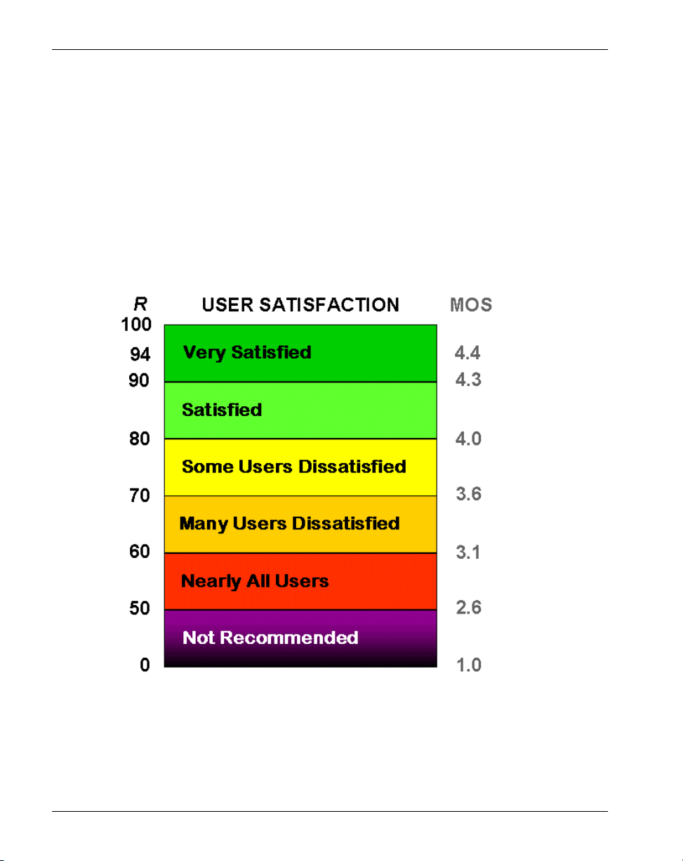
The E-model to measure audio quality and user satisfaction
The ITU developed what is called the E-model. The E-model uses the factors
described in “Introduction to packetized voice” on page 5 to derive a quality
value corresponding to the quality experienced by the VoIP system users.
The following graph shows the E-model rating, R value, versus the traditional
Mean Opinion Score (MOS) values.
Remote Gateway 9100 Series Network Engineering Guidelines 7
Page 8
Standard 1.6 June 2005
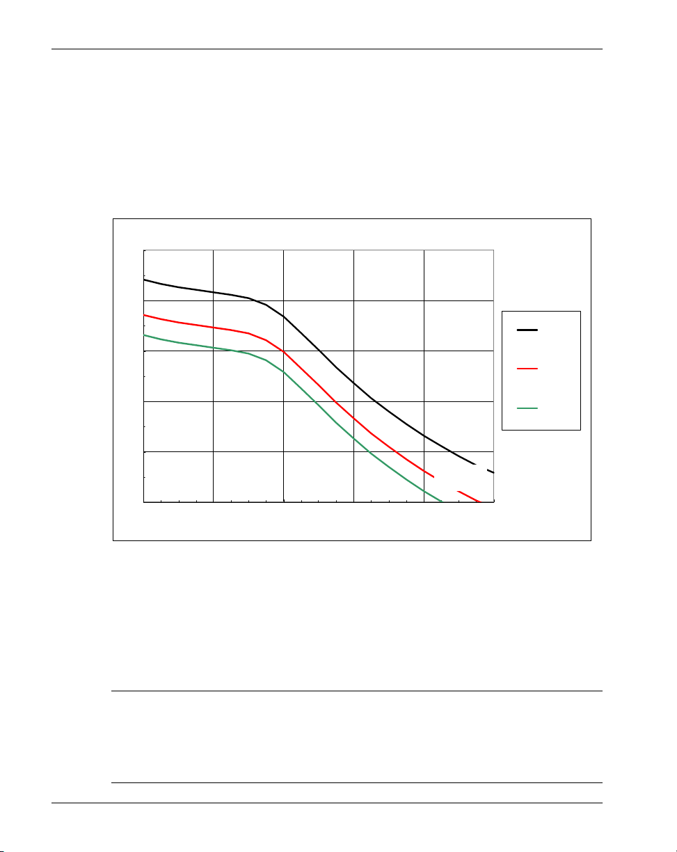
Compressed audio quality under ideal conditions
The following graph shows the Remote Gateway 9100 Series Codecs graphed
against the R value and conversational delay.
Remote Gate way 9100 Se rie s Code cs - No Impai rme nts
100
90
80
R
70
60
50
0 100 200 300 400 500
T
User Satisfaction
Very
satisfactory
Satisfactory
Some users
dissat isfied
Many user s
diss atis fied
Excepti onal
limiting case
G. 71 1
G. 72 6
G.729A
Note: T is one-way delay in milliseconds (ms).
To fully use this graph, you must know the Remote Gateway 9100 Series
inherent delay values. The critical values are as follows:
Codec
Encoding/
Decoding
BRI
Serialization
911x V.32
Serialization
G.711 - 64 Kbps 30 ms 25 ms -
G.726 - 32 Kbps 30 ms 12 ms -
G.729A - 8 Kbps 35 ms 10 ms 90 ms
8 Remote Gateway 9100 Series Network Engineering Guidelines
Page 9

Standard 1.6 June 2005
There are additional delays experienced that are a function of the customer
network:
end-to-end delay
The time it takes to pass an Internet Protocol (IP) packet from the RLC to
the Remote Gateway 9150 unit (or the opposite direction)
jitter buffer depth
If the network has low jitter, the jitter buffer can be reduced. The
configurable values in the Remote Gateway 9100 Series product are 30, 60,
or 90 ms.
Conversational delay calculation examples
Remote Gateway 9100 Series units over IP
When using the Remote Gateway 9100 Series units over IP, the controllable
delay factors are the jitter buffer and the network delay. For example, assuming
you are using G.711 with a 60 ms jitter buffer:
30 ms (G.711 encoding/decoding) + 20 ms (one-way network delay) + 60 ms
(jitter buffer) = 110 ms one-way delay
Remote Gateway 9150 unit over PSTN
In the following example, the RLC and Remote Gateway 9150 unit is
configured to use G.729A to reduce bandwidth requirements:
35 ms (G.729A encoding/decoding) + 10 ms (serialization delay) + 60 ms (jitter
buffer) = 105 ms one-way delay
Remote Gateway 911x series unit over PSTN
The Remote Gateway 911x series unit uses a V.32 modem emulation to provide
connectivity over the PSTN. In this configuration, you must use G.729A.
35 ms (G.729A encoding/decoding) + 90 ms (serialization delay) + 60 ms (jitter
buffer) = 185 ms one-way delay
Remote Gateway 9100 Series Network Engineering Guidelines 9
Page 10

Standard 1.6 June 2005
Remote Gateway 9150 unit to Remote Gateway 9150 unit
When a customer environment uses multiple Remote Gateway 9150 units, the
audio must be treated by each individual Remote Gateway 9150 unit. Therefore,
the delay each Remote Gateway 9150 unit experiences is added together. For
example, assuming one Remote Gateway 9150 unit over IP (G.711)
communicating to another Remote Gateway 9150 unit over BRI (G.729A):
30 ms (G.711 encoding/decoding) + 20 ms (one-way network delay) + 60 ms
(jitter buffer) + 35 ms (G.729A encoding/decoding) + 10 ms (serialization delay)
+ 60 ms (jitter buffer) = 215 ms one-way delay
Notes:
1. Since the audio has been compressed by the G.729A Codec, each user
experiences the quality provided by the G.729A Codec.
2. When calls are made from Remote Gateway 9150 unit to Remote Gateway
9150 unit as described, it is possible that the Echo Cancellers in the Remote
Gateway 9100 Series product can cause periods of audio clipping when the
conversational delay is large. To minimize this possibility, you must
manage network delay and jitter so that the jitter buffer depth can be
reduced as much as possible.
As you have calculated, when using IP connectivity, the network performance
can affect the jitter buffer depth and network delay, thus increasing the
conversational delay. The network can also have periods of high jitter or packet
loss that can greatly affect the audio quality.
10 Remote Gateway 9100 Series Network Engineering Guidelines
Page 11
Standard 1.6 June 2005
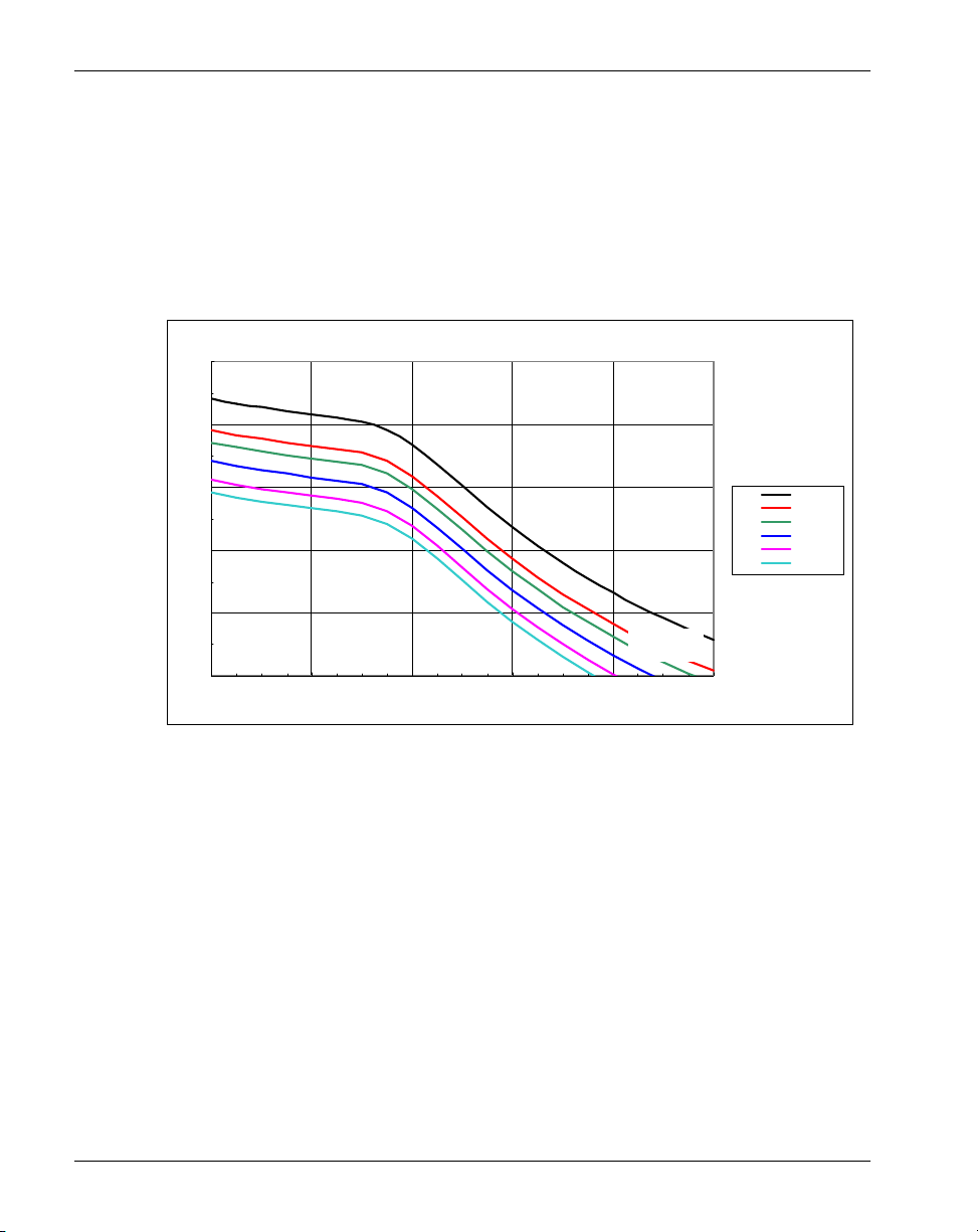
Compressed audio quality under packet loss conditions
The following graph shows the effect of random packet loss on the Remote
Gateway 9100 Series G.711 Codecs.
100
G.711 w ith Rand om Pack et Los s
90
80
R
70
60
50
0 100 200 300 400 500
T
Note: T is one-way delay in ms.
User Satisfaction
Very
satisfactory
Satisfac tory
Some us ers
dissat isf ied
Many users
dissatisf ied
Exceptional
limiting cas e
0
0.01
0.02
0.03
0.04
0.05
Remote Gateway 9100 Series Network Engineering Guidelines 11
Page 12
Standard 1.6 June 2005
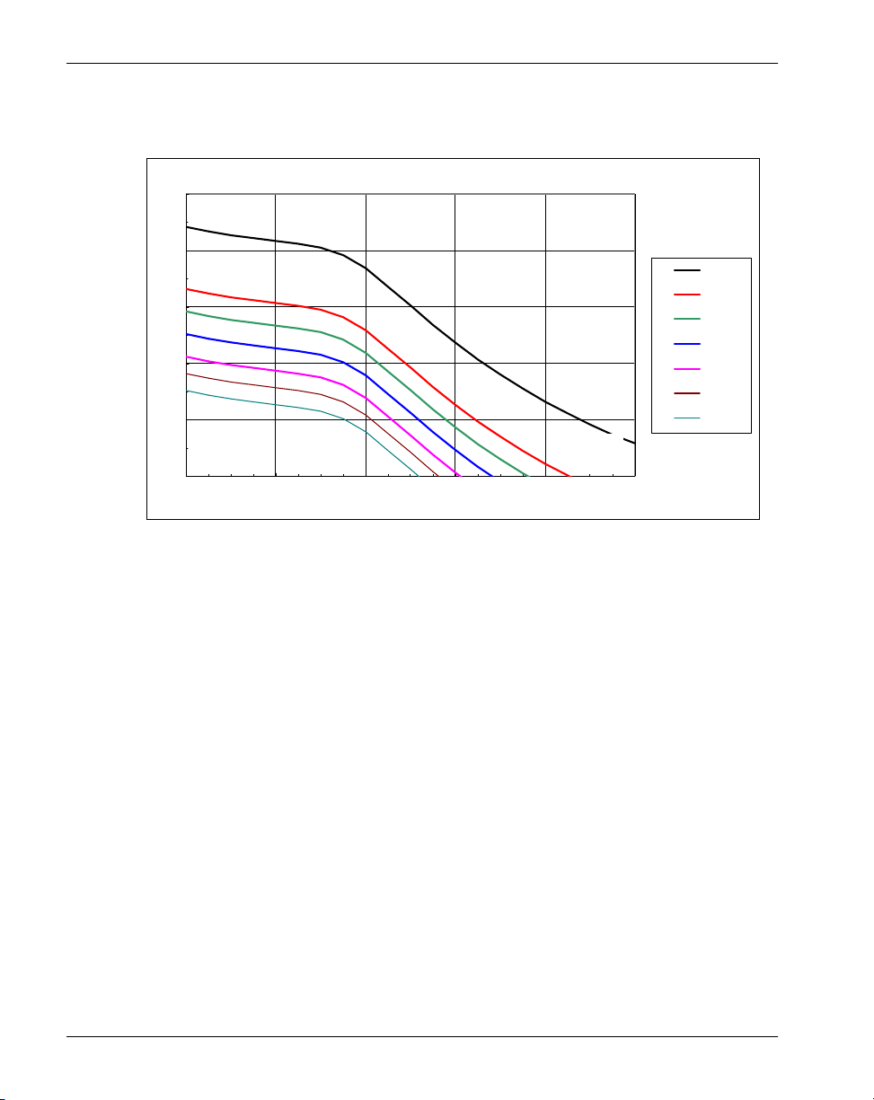
The following graph shows the effect of random packet loss on the Remote
Gateway 9100 Series G.729A Codecs.
100
90
80
R
70
60
50
0 100 200 300 400 500
G.729A w ith Rand om Pack et Los s
T
Use r Satis faction
Note: T is one-way delay in ms.
Very
satisf actory
Satisfac tory
Some user s
dissat isf ied
Many users
dissat isf ied
Exceptional
limiting case
G.711
0%
1%
2%
3%
4%
5%
12 Remote Gateway 9100 Series Network Engineering Guidelines
Page 13

Standard 1.6 June 2005
Evaluating your network
Now that you fully understand the effects of packet loss, jitter, and delay on the
audio quality that can be experienced on packetized voice equipment, the next
step is to ensure that the network is capable and configured to support
packetized voice.
A network is a dynamic entity – the characteristics change daily, hourly, by the
second as various applications push and pull data across it. The method of
evaluation best suited for packetized voice is testing with pseudo voice traffic
for extended periods of time.
There are numerous Personal Computer (PC) based software tools available that
generate a configured number of calls, using a specific Codec, for a configured
duration. The tool then provides various reports showing the jitter, packet loss,
and the equivalent audio quality (MOS or R-value). You can and should use this
tool before installing the VoIP equipment. You should run tests for an extended
period of time.
To ensure success, network evaluation is a critical step in engineering a VoIP
solution. Do not skip this critical step, as it is the foundation for the projects
success.
Nortel can provide network evaluation services, either directly or through our
business partners.
Network engineering for real time traffic
Packetized voice, or VoIP, is a form of real time traffic where delays and
retransmission cannot be tolerated. Typical PC and server traffic is non-real time
and, therefore, can tolerate a certain level of delay and retransmission. To ensure
that the VoIP traffic receives the most expedited treatment possible, there are a
number of techniques that you can use.
Let's look at the various techniques starting at the VoIP devices themselves and
working out into the Local Area Network (LAN) or Wide Area Network
(WAN).
Remote Gateway 9100 Series Network Engineering Guidelines 13
Page 14

Standard 1.6 June 2005
LAN access points
The RLC and Remote Gateway 9100 Series units all have Ethernet interfaces
that you can use for VoIP connectivity. Use the following table to locate
connectivity options at the device level:
Product Capability Minimum Revisions
RLC 10 M half or full-duplex 1.3.5 firmware for full-
duplex
Remote Gateway 9150
unit
Remote Gateway 911x
10 M half or full-duplex 1.4.0 hardware and
firmware for full-duplex
10 M half-duplex 1.3.1 firmware
series units and Digital
Telephone IP Adapter
units
It is common that the Remote Gateway 9100 Series product is directly plugged
into a hub or a switch as shown in the following illustration:
Consideration 1
When using a hub, the shared media causes all other hub traffic to be presented
to the Remote Gateway 9100 Series device also. The Remote Gateway 9100
Series product reports this traffic as multicast packets – packets that were not
specifically addressed for the Remote Gateway 9100 Series product itself. Since
the Remote Gateway 9100 Series product must read the packet to determine that
it should be ignored, a high level of multicast packets can be disruptive to real
time traffic. Keep the multicast traffic to less than five percent of the segment
traffic.
14 Remote Gateway 9100 Series Network Engineering Guidelines
Page 15

Standard 1.6 June 2005
Recommendation 1
A switch manages the traffic so only packets addressed for the Remote Gateway
9100 Series product are transmitted to the Remote Gateway 9100 Series product.
Nortel recommends that you connect the Remote Gateway 9100 Series product
to a data switch as shown in the following illustration:
Consideration 2
When the VoIP traffic is passed to the switch, the switch forwards the packet at
essentially wire line speed. When multiple devices receive multiple packets,
with the destination being on the uplink side of the switch, the switch must
temporarily buffer the packets as it manages the uplink media. Low end switches
do not provide a mechanism to manage the buffer process. Therefore, real time
traffic can experience a small amount of jitter due to buffering.
Recommendation 2
The Remote Gateway 9100 Series products support a prioritization methodology
called 802.1Q tagging. When the feature is enabled in the Remote Gateway
9100 Series products, the Ethernet Media Access Control (MAC) frame is
“tagged” with three bits that define the priority of the packet. When using a data
switch that is 802.1Q aware, the tagged data receives the appropriate priority
over low priority or untagged packets. The Remote Gateway 9100 Series
products set the 802.1Q code point to a hex value of C000. The following
illustration shows aggregation point uplink prioritization:
Remote Gateway 9100 Series Network Engineering Guidelines 15
Page 16

Standard 1.6 June 2005
Consideration 3
The uplink for the switch or hub is connected to either another switch or a router.
If it is an additional switch, recommendation 2 still applies, as well as using
802.1Q Virtual Local Area Network (VLAN) techniques to keep the real time
traffic prioritized at the Layer 2 level.
If you use a router as the uplink device, there are a number or prioritization
methods that can be used. Remember that even though prioritizing the traffic in
all directions is beneficial, the critical direction is when data is aggregated from
high speed links to a slow speed link.
There are three critical steps in managing real time traffic through a router, as
follows:
1. Recognizing that the traffic requires prioritization
2. Placing the traffic in the appropriate queues
3. Passing the traffic onto the next segment in a prioritized manner
Recommendation 3
The Remote Gateway 9100 Series products have the capability of marking IP
packets with a Differentiated Services (DiffServ) CodePoint. A router that is
aware of the DiffServ prioritization levels places the Remote Gateway 9100
Series traffic in the highest priority queue.
If DiffServ cannot be used to identify the real time traffic, the source,
destination, or port in the IP packet can be used to identify the Remote Gateway
9100 Series traffic. UDP port 0x5000 (20480) is used for voice traffic. UPD port
0x5002 (20482) is used to test during QoS Transition. TCP port 0x3200 (12800)
is used for the Remote Gateway 9100 Series product and telephone signaling.
Note: All packets are tagged with the DiffServ CodePoint you configure in
Remote Gateway 9100 Series Configuration Manager on the IP Configuration
property sheet for your specific unit. Refer to your Remote Gateway 9100 Series
unit’s Installation and Administration Guide for further details.
16 Remote Gateway 9100 Series Network Engineering Guidelines
Page 17

Standard 1.6 June 2005
There are multiple methods of creating queues in a router, each with different
depths, prioritizations, and so on. The queue that the voice traffic is placed in
must be deep enough to ensure that packets are not lost due to the queue being
full, but not too deep to cause excessive packet delay. Most router venders
follow the well known standards. Configuration of these techniques, however,
could vary greatly. Consult your equipment vendor for the exact configurations.
Routers can be provisioned to honor 802.1Q markings, and also honor or mark
the packets DiffServ setting at layer 3.
Understanding queuing techniques
Slower WAN links can add inherent delay to voice packet transversal. Often,
these types of links have voice and data converged, competing for the same
bandwidth availability. How this converged link affects voice quality is
completely dependant on the WAN link speed and encapsulation protocol.
Queuing techniques help to provide the most efficient method for guaranteeing
VoIP delivery while sharing the bandwidth with other data traffic.
Recommendation 4
For WAN serial links 768 Kbps or less, Nortel recommends that you use the
following packet fragmentation and queuing techniques:
Remote Gateway 9100 Series Network Engineering Guidelines 17
Page 18

Standard 1.6 June 2005
Recommendation Definition
packet fragmentation Fragmentation helps prevent a smaller VoIP packet
from being delayed behind a large data packet.
Fragmentation must be enabled on both ends of the
serial link. Depending on link speed, serialization
delay of a large, 1500 byte packet can cause a
smaller, 160 byte voice packet to exceed the endto-end budget delay of 150 ms. Fragmentation
breaks up the train of packets into evenly sized
packets. It is important not to fragment the VoIP
packets, only the competing data packets. Method
of fragmentation can vary, depending on the WAN
protocol. Frame Relay, as an example, can make
use of the FRF.12 standard and fragment at layer 2.
Point-to-Point Protocol (PPP) also has the ability to
fragment at layer 2. High-Level Data Link Control
(HDLC) links, however, can only be fragmented at
the IP layer, layer 3 by setting a maximum
Maximum Transmission Unit (MTU) size. Nortel
does not recommend this method due to the added
processing requirements, and unreliable results.
Note: Some Web applications can mark the packet
as “do not fragment”.
interleaving Interleaving is a technique to mix the VoIP packets
into a stream of data traffic. As an example, a large
file download can have multiple packets required to
complete the session. Fragmentation breaks up the
large packets into regular sized packets, while
interleaving inter-weaves VoIP packets with the
data packets.
18 Remote Gateway 9100 Series Network Engineering Guidelines
Page 19

Standard 1.6 June 2005
queuing techniques Queuing techniques help to isolate priority traffic,
such as VoIP, from the normal data traffic. By
placing the priority voice traffic into a separate
queue, or holding bucket, this type of traffic can be
given special treatment. As an example, the priority
traffic can be given dedicated bandwidth when the
link is congested. This helps ensure a timely
delivery of the VoIP packets. The different queuing
methods are as follows:
Priority Queuing (PQ) This is the legacy method of queuing to guarantee a
certain amount of available bandwidth. This
method has some inherent problems. As an
example, PQ can be very Central Processing Unit
(CPU) intensive, and starve other traffic types of
bandwidth. As long as the PQ queue is full, it does
not service the other queues. Today, PQ is
incorporated into more advance queuing methods
such as CBWFQ and LLQ. Refer to page 20 for
further details on CBWFQ and LLQ.
Customer Queuing (CQ) Developed to solve the PQ problems of bandwidth
starvation for the non-priority traffic. This method
uses a “round-robin” method to service the
difference queues.
Weighted Fair Queuing
(WFQ)
This is the most common default method of
queuing for interfaces 2 Mbps or less. WFQ
attempts to share the available bandwidth equally
for all applications by identifying the different
conversations. The “weighted” part of WFQ takes
note of the DiffServ CodePoint at layer 3 to give
priority treatment. Today, this method is combined
with the other queuing techniques (PQ and CQ) to
provide more queuing options.
Remote Gateway 9100 Series Network Engineering Guidelines 19
Page 20

Standard 1.6 June 2005
Class Based Weighted
Fair Queuing (CBWFQ)
This technique makes use of the WFQ method of
queuing and adds the ability to separate traffic into
different classes. The classes allow for more
flexibility for controlling traffic on a network. It
does not use the “guaranteed bandwidth” PQ
method, but does allow you to set aside a particular
amount of bandwidth for VoIP traffic. It also allows
you to configure different queuing methods for
other types of traffic, such as Web traffic.
Low Latency Queuing
(LLQ)
Known as PQ/CBWFQ, this technique adds the PQ
to CBWFQ by allowing you to guarantee a certain
amount of bandwidth for priority traffic, such as
Vo I P.
The following illustration shows high speed to low speed aggregation:
Consideration 5
The real time traffic is now in the appropriate queue waiting to be passed onto
the next segment. The timeliness of the delivery is important. Therefore, you
must review multiple considerations.
20 Remote Gateway 9100 Series Network Engineering Guidelines
Page 21

Standard 1.6 June 2005
Recommendation 5
Maximum Transmission Unit (MTU) is the maximum packet size that is placed
on the segment. Since the link speed is low, a large packet takes a larger amount
of time to transmit across the link. The following table shows the fragmentation
size versus the link speed, which is called the transmission time, or serialization
delay (shown in ms).
Fragmentation Size (Bytes)
Link Speed
(bps)
1500 1024 768 512 256 128
1536000 7.8 5.3 4.0 2.7 1.3 0.7
1024000 11.7 8.0 6.0 4.0 2.0 1.0
768000 15.6 10.7 8.0 5.3 2.7 1.3
512000 23.4 16.0 12.0 8.0 4.0 2.0
384000 31.3 21.3 16.0 10.7 5.3 2.7
256000 46.9 32.0 24.0 16.0 8.0 4.0
128000 93.8 64.0 48.0 32.0 16.0 8.0
64000 187.5 128.0 96.0 64.0 32.0 16.0
56000 214.3 146.3 109.7 73.1 36.6 18.3
Fragmentation = (link speed * serialization delay)/8
The ideal serialization delay is 8 ms or less. For example, on a 256 Kbps link,
the MTU should be 256 bytes.
Remote Gateway 9100 Series Network Engineering Guidelines 21
Page 22

Standard 1.6 June 2005
Note: A small MTU (less than 768 bytes) can cause performance degradation on
certain PC applications. Therefore, Nortel recommends that you use
fragmentation techniques such as FRF.12 or PPP fragmentation/interleaving,
rather than physically changing the MTU size. The following illustration shows
WAN considerations:
Consideration 6
Many Remote Gateway 9100 Series installations utilize a WAN provided by a
third party service provider. The customer leases the required service, and
depends on the WAN provider to maintain the required level of service. The
parameters that are often used to define the WAN service are as follows:
Parameter Definition
Frame Relay Service
Minimum Committed
Information Rate
(MinCIR)
The minimum amount of data to be sent during
periods of congestion. Defaults to half CIR in most
circumstances.
Burst Committed (Bc) The number of bits to transmit in the specified
amount of time interval (Transmission Control
[Tc]).
Burst Excess (Be) The number of bits to transmit in the first interval
of active transmission, once credit has been built
up.
Transmission Shaping
Interval (Tc)
22 Remote Gateway 9100 Series Network Engineering Guidelines
The period of transmission for Frame Relay
Permanent Virtual Connection (PVC).
Page 23

Standard 1.6 June 2005
Traffic Shaping This is a method of throttling transmission from a
fast to slow link by adjusting the credit manger or
token bucket.
Adaptive Shaping A method to throttle transmission using the
Backward Excessive Congestion Notification
(BECN) technique inherent to Frame Relay when
CIR is exceeded.
Asynchronous Transfer
Mode (ATM) Service
Sustainable Cell Rate
The averaged cell rate over a period of time.
(SCR)
Peak Cell Rate (PCR) The maximum cell rate, normally equals port
speed.
Maximum Burst Size
(MBS)
Real Time Variable Bit
Rate (rt-VBR)
Non-real Time Variable
Bit Rate (nrt-VBR)
The amount of bandwidth that can be utilized if a
burst occurs.
A level of ATM service that guarantees the cell loss
and end-to-end delay characteristics.
This is similar to rt-VBR, but the amount of delay
is not specified. Therefore, jitter can be a problem.
Nortel does not recommend this for real time traffic
such as voice.
Available Bit Rate
(ABR)
A guaranteed minimum amount of bandwidth is
defined, but the delay and loss parameters are not
specified when a defined peak is reached. Nortel
does not recommend this for real time traffic unless
you use strict flow control mechanisms.
Unspecified Bit Rate
(UBR)
Designed for bursty, non-real time applications,
this service does not specify delay or loss
parameters.
Remote Gateway 9100 Series Network Engineering Guidelines 23
Page 24

Standard 1.6 June 2005
Guaranteed Frame Rate
(GFR)
A guaranteed minimum amount of bandwidth is
defined, but the delay and loss parameters are not
specified when the minimum is surpassed. Nortel
does not recommend this for real time traffic.
Cell Loss Priority (CLP) This is a bit that determines if a cell should be
dropped due to excessive congestion.
Recommendation 6
Test the service provided by the WAN service provider. It is quite likely that real
time data is being passed along side of non-real time data from other customers.
All of the good prioritization work performed on the customer network could be
undone by a poor WAN. For example, non-real time traffic should have the
Discard Eligible (DE) bit set, so that during periods of congestion, it is dropped
before real time traffic.
For Frame Relay VoIP, Nortel recommends the following:
Do not exceed the CIR of the PVC:
— Queuing of voice packets must be minimized.
— If the CIR is exceeded, packets are normally queued in the Frame Relay
cloud.
— Maintain a value at or below CIR.
Do not use Frame Relay Adaptive Shaping:
— Adaptive Shaping utilizes BECNs to shape or throttle down traffic
transmission if the CIR is exceeded.
Set the value of Burst Committed (Bc) low so the Transmission Shaping
Interval (Tc) is small (Tc = Bc/CIR):
— (Tc) value should be around 10 ms.
— A small value ensures that large packets do not use up all the available
credits.
— A large (Tc) value can lead to large gaps between packets sent. This is
due to the traffic shaper waiting an entire (Tc) period before sending the
next frame.
24 Remote Gateway 9100 Series Network Engineering Guidelines
Page 25

Standard 1.6 June 2005
For ATM to Frame Relay links, Nortel recommends the following:
Be sure to properly map Frame Relay parameters (CIR, Bc, and Be) into
equivalent ATM values.
— Use FRF.8 (RFC 1490), Section 5.1. FRF.8 details the method of
interworking between a Frame Relay end-point and an ATM end-point
Inherent differences exist, such as PCR and SCR are expressed in cells per
second (cps), ABR and CIR are expressed in bytes per second (bps), and
ATM uses a fixed cell size of 53 bytes.
— To deliver an equivalent bandwidth to actual user traffic, choose the
values of PCR and SCR to include the extra margin required to
accommodate the overhead introduced in transferring the Frame Relay
frames through an ATM network.
Remote Gateway 9100 Series Network Engineering Guidelines 25
Page 26

Standard 1.6 June 2005
Bandwidth usage table
The values shown in the following table are the bandwidth requirements when
using IP as the medium.
Packet Size G.711
1
G.7 26
1
G.729A
1
G.729A\FAX
Voice Payload (bytes/30 ms) 240 120 30 38
Voice header (bytes) 12 12 12 12
UDP header (bytes) 8 8 8 8
IP header (bytes) 20 20 20 20
IP Packet Size (bytes) 280 160 70 78
LAN Overhead
Ethernet header Size (bytes) 14 14 14 14
IP Packet Size (bytes) 280 160 70 78
LAN Packet Size (bytes)
3
294 174 84 92
Peak Data Rate (Kbps) 78 46 22 24
4
Avg Data Rate-w/silence (Kbps)
47 28 13 24
IP Over Frame Relay Overhead
Frame Relay Overhead (bytes) 4 4 4 4
RFC 1490 IP Overhead (bytes) 2 2 2 2
IP Packet Size (bytes) 280 160 70 78
Frame size (bytes) 286 166 76 84
Peak Data Rate (Kbps) 76 44 20 22
4
Avg Data Rate-w/silence (Kbps)
46 27 12 22
2
1,
5
5
1. compression algorithm
2. 9600 bps (14400 bps not supported)
3. The Remote Gateway 911x series and Digital Telephone IP Adapter units transmit packets that
are based on 64 byte boundaries. In other words, G.729A equals 128 bytes and G.711 equals 320
bytes. The Remote Gateway 911x series and Digital Telephone IP Adapter units do not support
G.726.
4. Average data rate with silence suppression is approximately 60% of Peak. Change this number to
reflect the site’s actual values.
5. Silence suppression, or voice activity detection (VAD) is disabled.
26 Remote Gateway 9100 Series Network Engineering Guidelines
Page 27

Standard 1.6 June 2005
When using the Remote Gateway 9100 Series products with PSTN bandwidth,
the requirements are as follows:
G.711 = 64 Kbps
G.726 = 32 Kbps
G.729A = 8 Kbps
If VAD is disabled, the PSTN bandwidth requirements increase by 20% due to
inefficiencies in the HDLC protocol used.
Remote Gateway 9100 Series Network Engineering Guidelines 27
Page 28

Standard 1.6 June 2005
Quality of service issues
The following section discusses ways that the Remote Gateway 9100 Series
product works to resolve Quality of Service (QoS) issues involved in
transmitting VoIP.
QoS Transitioning Technology
When voice quality degrades on your Remote Gateway 9100 Series network, the
RLC provides improved QoS. Nortel’s patented QoS Transitioning Technology
enables the RLC to move Remote Gateway 9100 Series calls from the IP
network to the PSTN. The more stable PSTN provides improved QoS until IP
network QoS improves.
Once the IP network QoS improves, the RLC automatically recovers Remote
Gateway 9100 Series calls to the IP network. For detailed information on how to
configure QoS Transitioning Technology thresholds, refer to the Reach Line
Card Installation and Administration Guide (NTP 555-8421-210).
Note: Because Digital Telephone IP Adapter units do not have PSTN
connectivity, they do not support QoS Transitioning Technology.
How QoS Transitioning Technology works
QoS Transitioning Technology bases transition and recovery functions on the IP
network’s QoS level. The QoS level is a user-oriented metric that takes one of
ten settings. You identify the limits of acceptable voice QoS for each remote site
in your Remote Gateway 9100 Series network by choosing from among those
settings using Remote Gateway 9100 Series Configuration Manager graphical
user interface (GUI). The Meridian digital telephone set at the remote location
and the RLC in the host PBX communicate with one another over the IP
network. These communications begin with a 10BaseT Ethernet interface to the
corporate intranet.
28 Remote Gateway 9100 Series Network Engineering Guidelines
Page 29

Standard 1.6 June 2005
The RLC and the remote units constantly monitor the QoS level on the data
paths between the host PBX and the individual remote sites. Each node
calculates the prevailing QoS level based upon the following factors:
jitter
delay
packet loss
compression algorithm
The RLC calculates the QoS level based upon ANSI TR56 and the E-model
found in ITU-T Reg. G.114. When the QoS level falls below the specified
transition threshold for the specified period of time, or duration, the receiving
Remote Gateway 9100 Series node rejects the call. The RLC then reroutes the
call over the PSTN. When the QoS rises to a point above the specified recovery
threshold for the specified period, the RLC restores calls to the IP network. You
configure thresholds and durations for each remote site.
When transitioning or recovering multiple calls, the RLC moves calls between
the IP network connection and the PSTN connection based on the Kbps you
configure. The system waits several seconds between the units of Kbps you
configure to determine if the IP connection has become more stable.
Note: Configure the Kbps using the RLC’s Remote Connection Configuration
property sheet in Configuration Manager. Click on the Quality of Service button,
then enter the Kbps in the Transition Bandwidth field on the Quality of Service
dialog box.
The RLC moves as many calls as possible (to a maximum of 64 Kbps for each
B-channel) from the IP connection to the PSTN trunk connection. High priority
users always move first. For information on configuring priority, refer to the
Reach Line Card Installation and Administration Guide (NTP 555-8421-210).
transparent transition and recovery
Transitions can take place during a live call and are transparent to users
who only notice improved voice quality. In the case of a complete IP
network failure, however, a noticeable break in the call of approximately
four seconds occurs. This allows the RLC to transition the call to the PSTN.
Note: When IP degradation causes the RLC to transition calls to the PSTN,
a momentary degradation in voice quality can occur as the transition takes
place.
Remote Gateway 9100 Series Network Engineering Guidelines 29
Page 30

Standard 1.6 June 2005
network testing
Both the RLC and the Remote Gateway 9100 Series unit (Remote Gateway
9150 and 911x unit) run an IP test to determine if the QoS on the IP
network meets configured standards. (For more details, refer to “Measuring
QoS while offline” on page 32.) To configure QoS Transitioning
Technology thresholds, use the Remote Gateway 9100 Series Configuration
Manager. For further information, refer to the Reach Line Card Installation
and Administration Guide (NTP 555-8421-210).
The chart on page 30 illustrates how QoS Transitioning Technology works on
the RLC, Remote Gateway 911x series unit, and Remote Gateway 9150 units.
The same chart depicts Z and Q as equal periods of time. However, the duration
of poor voice quality required for transition to the PSTN, Z, is a period of
seconds. The duration of good voice quality required for recovery to the IP
network, Q, is a period of minutes. The units of time used to identify acceptable
points of transition and recovery differ in an attempt to minimize transition
thrashing. Transition thrashing is the rapid transition and recovery between the
PSTN and the IP network. This can occur when QoS hovers around configured
degrade and recover thresholds producing higher than normal PSTN charges.
In the telephone call represented by the chart on page 30, signal quality begins in
the acceptable range; that is, signal quality is above the X threshold. While
signal quality remains in the acceptable range, the RLC routes calls through the
IP network.
transition
When IP QoS degrades below the X threshold, the RLC waits for duration
Z to increase the likelihood of continued unacceptable voice QoS. If the
voice QoS remains below the X threshold for duration Z, the RLC
establishes a communication path for that call on the PSTN. The RLC then
transitions the call to the newly established PSTN channel.
recovery
After the RLC transitions a call to the PSTN, when IP QoS exceeds the Y
threshold, the system waits for duration Q. Again, this increases the
likelihood of continued acceptable voice QoS on the IP network. After
duration Q passes, the RLC moves all current calls back to the IP network
and places all new calls over the IP network.
30 Remote Gateway 9100 Series Network Engineering Guidelines
Page 31

Standard 1.6 June 2005
The setting represents
X signal quality on the IP network is unacceptable below this
point.
Y signal quality on the IP network is acceptable above this point.
Z the amount of time that signal quality must be lower than the X
threshold before the RLC transitions calls to the PSTN.
Q the amount of time that signal quality must be higher than the Y
threshold before the RLC recovers calls to the IP network.
Remote Gateway 9100 Series Network Engineering Guidelines 31
Page 32

Standard 1.6 June 2005
QoS traffic measurements
As voice packets travel across the IP network, the RLC monitors the following
QoS parameters:
average packet delay
The RLC calculates this delay using the following statistics gathered from
its voice jitter attenuation buffer:
— minimum packet holding time in the jitter buffer
— maximum packet holding time in the jitter buffer
— peak holding time in the jitter buffer
— time-stamp values in the packet header
By accumulating these statistics over time, the RLC can calculate an
average packet delay value through the IP network. As the system detects
an increase in the average packet delay, it references the signal degrade
threshold to determine when to make the transition to the PSTN
connection.
For a further description of statistics, refer to the Reach Line Card
Installation and Administration Guide (NTP 555-8421-210).
lost packets
The RLC calculates lost packet statistics by accumulating the following
packet header and voice decoder statistics:
— voice decoder underrun
— voice decoder overrun
— out-of-sequence packet reception
Measuring QoS while offline
Once the RLC reverts to using its PSTN connections, it must continually
monitor the IP network. The RLC determines an appropriate time to restore
voice traffic to the IP network as follows:
1. Both the RLC and the Remote Gateway 9100 Series unit (Remote Gateway
9150 and 911x) place pseudo-voice traffic on the IP network.
Both the RLC and the Remote Gateway 9100 Series unit send traffic with a
maximum bandwidth of no more than 16 Kbps in short bursts at a higher bit
rate to approximate live voice traffic.
32 Remote Gateway 9100 Series Network Engineering Guidelines
Page 33

Standard 1.6 June 2005
2. Both the RLC and the Remote Gateway 9100 Series unit (Remote Gateway
9150 and 911x) gather statistics based on the pseudo voice traffic to
determine the congestion levels on the network. They use packet time
stamps and sequence numbers to monitor the following parameters:
average end-to-end delay
average round-trip delay
average packet-to-packet jitter
average packet loss
3. When the parameters listed in step 2 fall below the predetermined threshold
for the predetermined period of time, the RLC restores voice traffic to the
IP network.
When restoring the connection to the IP network, the system adds
hysteresis, or delay, to reduce the noise level during the transition.
Note: Hysteresis, or delay, prevents thrashing between the PSTN and the
IP network (for a discussion of transition thrashing, refer to page 30), and
ensures that acceptable voice QoS exists on the IP network for a predefined
period of time.
Log reports and statistics
The Remote Gateway 9100 Series Configuration Manager provides a statistics
log that identifies the number of QoS transitions. For a detailed description of
log and statistic reports, refer to the Reach Line Card Installation and
Administration Guide (NTP 555-8421-210).
Telephone display messages
Meridian digital telephone sets with display capability can display the following
Resource Limit messages:
Bandwidth Limit indicates that there is insufficient BRI bandwidth
available to complete the requested action.
DSP Limit indicates that there are insufficient DSP resources available to
complete the requested action.
Remote Gateway 9100 Series Network Engineering Guidelines 33
Page 34

Standard 1.6 June 2005
Relationship between users and services
In the context of a host PBX and Remote Gateway 9150 unit, there are two
interfaces that you must consider in the relationship between users and services:
The Remote Gateway 9100 Series node (that is, the RLC on the host PBX
and the Remote Gateway 9100 Series unit at the remote site) provides an
interface to the Remote Gateway 9100 Series system for end users. Voice
services offered by the Remote Gateway 9100 Series node must meet useroriented QoS objectives. Refer to “Quality of service issues” on page 28 for
details.
The Remote Gateway 9100 Series nodes also provide an interface with the
intranet (or Internet in the case of a Remote Gateway 911x series unit). The
intranet provides the “best-effort delivery of IP packets,” as opposed to
“guaranteed QoS for real-time voice transport.” The Remote Gateway 9100
Series node translates the QoS objectives set by the end-users into IPoriented QoS objectives. This document refers to these objectives as
intranet QoS objectives.
34 Remote Gateway 9100 Series Network Engineering Guidelines
Page 35

Standard 1.6 June 2005
Ordering ISDN lines
The following section provides you with information regarding the ordering of
ISDN lines.
What you need to tell your ISDN service provider
Inform your ISDN service provider that you need the following:
two B-channels providing both voice and data capability (56 or 64 Kbps
clear, depending on your system)
Note: Both B-channels must be PSTN voice and data. Also, although
Nortel requires 56 or 64 Kbps clear, 64 Kbps clear is preferred.
Caller Line Identification (CLID, known in the United Kingdom as Calling
Line Identity Presentation–CLIP)
Multiple Subscriber Numbering (MSN)
two directory numbers (DNs)
two Service Profile Identifiers (SPIDs)
Note: MSN is required in situations where no SPIDs are provided.
Tell your service provider how the line should be provisioned for data, voice,
and other optional services. Different service providers require this information
in different ways; increasingly they are using ISDN Order Codes for simplicity,
but some still require specific switch type details.
What you need from your ISDN service provider
Your service provider needs to tell you:
the ISDN service and switch type
the ISDN directory numbers
associated SPIDs
bearer capability (56 or 64 Kbps)
Remote Gateway 9100 Series Network Engineering Guidelines 35
Page 36

Standard 1.6 June 2005
Supported ISDN switches and services for North America
The Remote Gateway 9150 unit supports the most common switch types. The
following table shows the ISDN services available for each of the switch types.
Switch Type ISDN Service
Nortel DMS-100 National ISDN 1 (NI-1)
National ISDN 2 (NI-2)
AT&T 5ESS Custom Point-to-Point
Custom Multipoint
National ISDN 1 (NI-1)
National ISDN 2 (NI-2)
Siemens National ISDN 1 (NI-1)
National ISDN 2 (NI-2)
Supported European ISDN services
For European installations, the Remote Gateway 9150 unit supports countryspecific EuroISDN installations, but does not support pre-EuroISDN
installations.
Using supplementary services
Nortel does not recommend the following supplementary data services for use
with Remote Gateway 9150 and 911x units:
call waiting
bearer-channel bonding
call-waiting ID
hunt
36 Remote Gateway 9100 Series Network Engineering Guidelines
Page 37

Standard 1.6 June 2005
If you need to order Hunt services, order Multiline hunting rather than
Overflow (EKTS) forward. The following must be true when you order
these services on the BRI circuits:
— The B-channel requested during call set-up must be the B-channel that
the call presents to
— The CALLED DN must be the DN of the B-channel the call presents to
Any other services, such as Forward on Busy must follow the guidelines
above.
Example A
1 BRI circuit
B1: 416-555-1212, the published number
B2: 416-555-1213
A PSTN set calls B1.
The published number is currently busy.
Hunt must provide a call setup message for B2 with a CALLED
number of 416-555-1213.
Example B
1 BRI circuit
B1: 416-555-1212
B2: 416-555-1213
The published number is different - 416-555-5000.
No calls are up.
When a PSTN set calls 416-555-5000, the call presents to B1 with a
CALLED CLID of 416-555-1212.
Remote Gateway 9100 Series Network Engineering Guidelines 37
Page 38

Page 39

Page 40

Remote Gateway 9100 Series Network Engineering Guidelines
Copyright © Copyright © 2000–2005 Nortel. All Rights Reserved.
Printed in Canada.
All information contained in this document is subject to change without notice. Nortel reserves the
right to make changes to equipment design or program components, as progress in engineering,
manufacturing methods, or other circumstances may warrant.
*Nortel, the Nortel logo, the Globemark, Meridian 1 PBX, Communication Server 1000 (CS 1000),
and Communication Server 2100 (CS 2100) are trademarks of Nortel.
Publication number: 555-8421-103
Product release: 1.6
Document release: Standard 1.6
Date: June 2005
 Loading...