

Nortel Picocell 1900 Installation Manual

Picocell 1900 Radio Unit Installation
Installation Method – 02-0245
September 3, 1998
Issue Number: 01.02
Information subject to change without notice. This is a DRAFT copy
for review and to provide advance information. Document release
subject to IM verification. Errors, omissions and corrections should be
sent to: lthomp@nortel.com
Pkgid: 0000003
PROPRIETARY INFORMATION: The information contained in this document
is the property of Nortel (Northern Telecom). Except as specifically authorized
in writing, the holder of this document shall keep all information contained
herein confidential and shall protect same in whole or in part from disclosure
and dissemination to third parties.
Draft
Nortel 1998
All Rights Reserved


September 3, 1998 Method 02-0245
Table of Contents
1.0 General Information . . . . . . . . . . . . . . . . . . . . . . . . . . . . . . . . . . . . . . . . . . . . . . . . . . . . . . . 7
1.1 Description . . . . . . . . . . . . . . . . . . . . . . . . . . . . . . . . . . . . . . . . . . . . . . . . . . . . . . . . . . . . 7
1.2 Sequence . . . . . . . . . . . . . . . . . . . . . . . . . . . . . . . . . . . . . . . . . . . . . . . . . . . . . . . . . . . . . 7
1.3 Reason for Reissue . . . . . . . . . . . . . . . . . . . . . . . . . . . . . . . . . . . . . . . . . . . . . . . . . . . . . . 7
2.0 Material Requirements . . . . . . . . . . . . . . . . . . . . . . . . . . . . . . . . . . . . . . . . . . . . . . . . . . . . . 9
2.1 Required Documents . . . . . . . . . . . . . . . . . . . . . . . . . . . . . . . . . . . . . . . . . . . . . . . . . . . . 9
2.2 Tools . . . . . . . . . . . . . . . . . . . . . . . . . . . . . . . . . . . . . . . . . . . . . . . . . . . . . . . . . . . . . . . . . 9
2.3 Stock List and Mounting Kits . . . . . . . . . . . . . . . . . . . . . . . . . . . . . . . . . . . . . . . . . . . . . . 9
2.4 Customer Supplied Equipment . . . . . . . . . . . . . . . . . . . . . . . . . . . . . . . . . . . . . . . . . . . . 10
3.0 Precautions and Preparations . . . . . . . . . . . . . . . . . . . . . . . . . . . . . . . . . . . . . . . . . . . . . . 11
3.1 Precautions . . . . . . . . . . . . . . . . . . . . . . . . . . . . . . . . . . . . . . . . . . . . . . . . . . . . . . . . . . . 11
3.2 Preparations . . . . . . . . . . . . . . . . . . . . . . . . . . . . . . . . . . . . . . . . . . . . . . . . . . . . . . . . . . 11
4.0 Procedure . . . . . . . . . . . . . . . . . . . . . . . . . . . . . . . . . . . . . . . . . . . . . . . . . . . . . . . . . . . . . . . 13
4.1 Overview . . . . . . . . . . . . . . . . . . . . . . . . . . . . . . . . . . . . . . . . . . . . . . . . . . . . . . . . . . . . . 13
Procedure 1 – Unpacking and Inventory transciever Material . . . . . . . . . . . . . . . . 14
Procedure 2 – Wall Mounting and securing the Radio Mounting Bracket . . . . . . . 15
Procedure 3 – Ceiling Mounting and securing the Radio Mounting Bracket . . . . . 17
Procedure 4 – Installation of PICOCELL Transceiver onto Wall Mounting Bracket 19
Procedure 5 – Co-located AC power supply Installation . . . . . . . . . . . . . . . . . . . 20
Procedure 6 – Remote AC power supply Installation . . . . . . . . . . . . . . . . . . . . . . 21
4.2 Power Supply connections . . . . . . . . . . . . . . . . . . . . . . . . . . . . . . . . . . . . . . . . . . . . . . . 22
4.3 PICOCELL Transceiver Connections . . . . . . . . . . . . . . . . . . . . . . . . . . . . . . . . . . . . . . . 23
Draft
5.0 References . . . . . . . . . . . . . . . . . . . . . . . . . . . . . . . . . . . . . . . . . . . . . . . . . . . . . . . . . . . . 24
6.0 Appendices . . . . . . . . . . . . . . . . . . . . . . . . . . . . . . . . . . . . . . . . . . . . . . . . . . . . . . . . . . . . . 25
Appendix A - PICOCELL 1900 transciever Cover removed Top view . . . . . . . . . . . . . . 25
Appendix B - Mounting Orientation and Isolation . . . . . . . . . . . . . . . . . . . . . . . . . . . . . . 26
Appendix C - Picocell 1900 Technical Specifications . . . . . . . . . . . . . . . . . . . . . . . . . . . 27
AC REQUIREMENTS . . . . . . . . . . . . . . . . . . . . . . . . . . . . . . . . . . . . . . . . . . . . . . . . . . 27
Picocell 1900 Power Supply Specifications . . . . . . . . . . . . . . . . . . . . . . . . . . . . . . . . . . 28
Last Page . . . . . . . . . . . . . . . . . . . . . . . . . . . . . . . . . . . . . . . . . . . . . . . . . . . . . . . . . . . . . 28
Picocell 1900 Radio Unit Installation / 3

Method 02-0245 September 3, 1998
Draft
4 / Picocell 1900 Radio Unit Installation

September 3, 1998 Method 02-0245
Illustrations
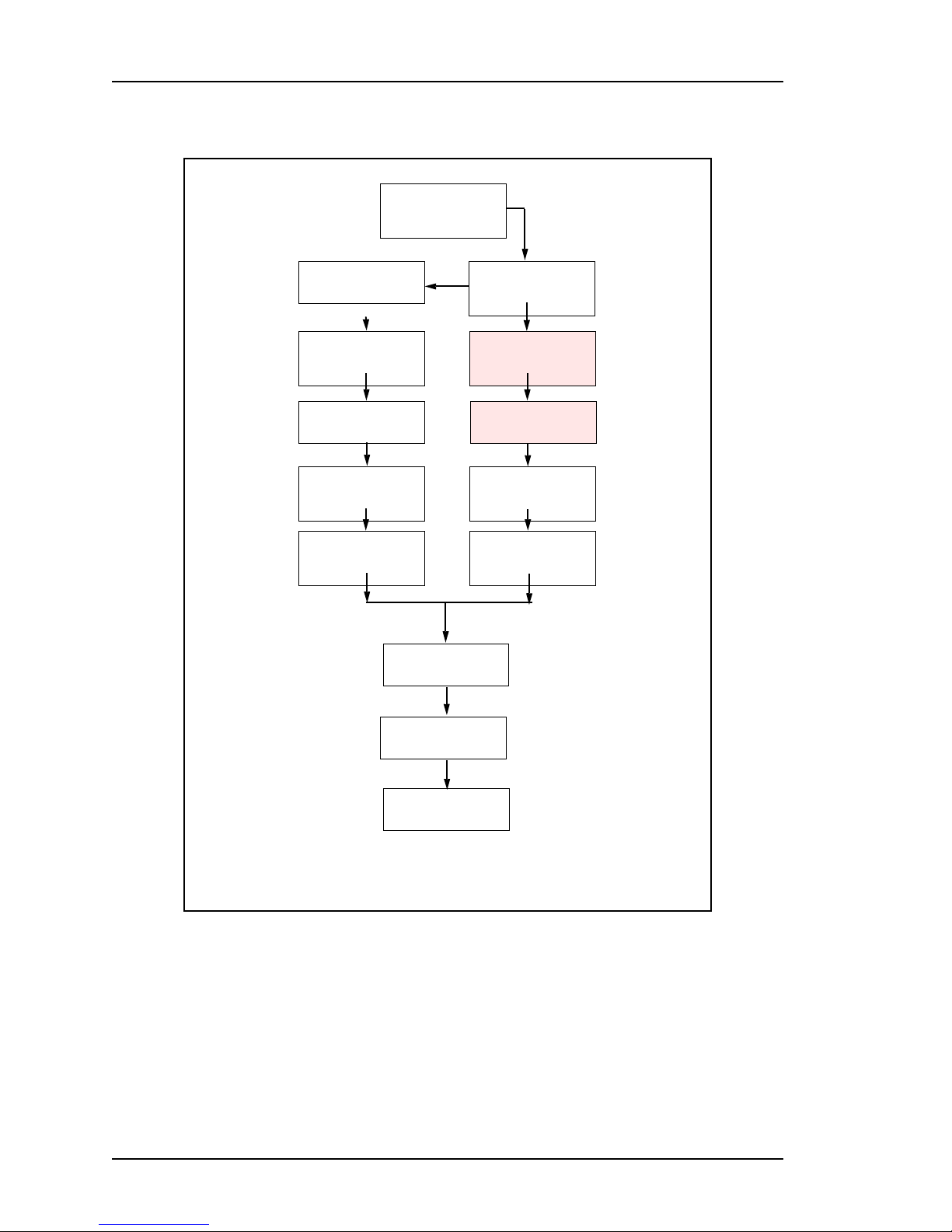
Figure 1 – You are here diagram . . . . . . . . . . . . . . . . . . . . . . . . . . . . . . . . . . . . . . . . . . . . . . 8
Figure 2 – PICOCELL 1900 front view . . . . . . . . . . . . . . . . . . . . . . . . . . . . . . . . . . . . . . . . . 10
Figure 3 – PICOCELL 1900 transciever Assembly . . . . . . . . . . . . . . . . . . . . . . . . . . . . . . . . 12
Figure 4 – PICOCELL 1900 Bottom view . . . . . . . . . . . . . . . . . . . . . . . . . . . . . . . . . . . . . . . 16
Figure 5 – PICOCELL 1900 Wall Mount . . . . . . . . . . . . . . . . . . . . . . . . . . . . . . . . . . . . . . . 16
Figure 6 – Track Ceiling support IDSClips . . . . . . . . . . . . . . . . . . . . . . . . . . . . . . . . . . . . . . 18
Figure 7 – PICOCELL 1900 transciever Ceiling mounting . . . . . . . . . . . . . . . . . . . . . . . . . . 18
Figure 8 – Locking the transciever into the mounting Bracket . . . . . . . . . . . . . . . . . . . . . . . . 19
Figure 9 – PICOCELL 1900 Co-located power supply . . . . . . . . . . . . . . . . . . . . . . . . . . . . . 20
Figure 10 – Remote Power Supply Mounting (Typical) . . . . . . . . . . . . . . . . . . . . . . . . . . . . . 21
Figure 11 – Power supply and connections . . . . . . . . . . . . . . . . . . . . . . . . . . . . . . . . . . . . . . 22
Figure 12 – PICOCELL 1900 transciever Connections . . . . . . . . . . . . . . . . . . . . . . . . . . . . . 23
Figure 13 – PICOCELL 1900 cabling and connections . . . . . . . . . . . . . . . . . . . . . . . . . . . . 23
Draft
Picocell 1900 Radio Unit Installation / 5

Method 02-0245 September 3, 1998
Tables
Tools 13
Stock List and Mounting Kits 14
Mounting Hardware 14
Draft
6 / Picocell 1900 Radio Unit Installation

September 3, 1998 Method 02-0245
1.0 General Information
1.1 Description
Purpose
PICOCELL 1900 Transceiver).
Equipment
hardware.
Application:
and extensions.
Service Impact
: This method will describe how to unpack and install the
: The PICOCELL 1900 Transceiver and mounting
This method will cover installation of initials, upgrades
: There is no service impact at this time.
1.2 Sequence
1. This method is to be performed after the building cabling has been
installed and is ready to recieve the PICOCELL 1900 Transceivers.
2. PICOCELL 1900 Planning Method 04-0242 has been reviewed.
1.3 Reason for Reissue
Changes from Project Team Review Sept 1, 1998:
Draft
• Updated section 4.2 Power supply
• Revised figures 5, 8, 9
• Section 5 removed reference
• Global change MBS1900 to Picocell 1900
• Cleared Table 3 contents until mounting hardware is finalized
Picocell 1900 Radio Unit Installation / 7
Method 02-0245 September 3, 1998
Figure 1 – You are here diagram
IM 04-0242
PICOCELL 1900
General Information
and Plannng
Educate Yourself
CSI Installation and
CSI Handling and
Draft
CSI Handling and
Cabling and Cross
Radio and CSI Power
IM 04-0241
Planning
IM 04-0243
securing
IM 04-0243
securing
IM 04-0244
PICOCELL 1900
Connect
IM 04-0246
PICOCELL 1900
up
Mount the back board
and plan lay out s
Install the CSI bracket
and mount the CSI and
PICOCELL 1900 power
supplies
Mount the CSI cross-
connect blocks
Cable the CSI to the
cross-connect blocks
Power up CSI
Commission PICOCELL
1900 transcievers
Check the sit e and pl an
the Job
Install PICOCELL 1900
mounting bracket(s),
Hybrids and Antennas
Make PICOCELL 1900
Connections and lock
into bracket
Jumper PICOCELL
1900 to CSI and power
supply on cross-connect
blocks
Power up PICOCELL
1900 Radios and
perform commissioning
test
IM28-0248
Radio Commisioning with
the IFR
IM02-0242
PICOCELL 1900
General Information
and Plannng
IM02-0245, 12-0152
PICOCELL 1900 Unit
and Antenna
Installation
IM02-0245
PICOCELL 1900 Unit
Installation
IM 04-0244
PICOCELL 1900
Cabling and Cross
Connect
IM 04-0246
PICOCELL 1900
Radio and CSI Power
up
Load CSI and Radio
software and run
diagnostics
Test Integrated System
IM28-0247
CSI Equipment Loading
and Diagnostics
IM02-0249
Microcell System
Test
8 / Picocell 1900 Radio Unit Installation

September 3, 1998 Method 02-0245
2.0 Material Requirements
2.1 Required Documents
Installation Safety Manual (ISM/IM0) - can be requested from the
Regional Tool Facility.
2.2 Tools
The tools listed in Figure 2 are required to perform this method.
Table 1 – Tools
U.S. Tool
Tool Kit Tool Kit Installers Tool Kit
Canadian
Tool
2.3 Stock List and Mounting Kits
Table 2 – Stock List and Mounting Kits
Quantity CPC/PEC Product Description
1
1
P0880222
NTMQ7025
NTMQ40AA
NTMQ50AA
NTMQ60AA
NTMQ70AA
NTMQ75AA
PICOCELL 1900 Mounting bracket
PICOCELL Point of Use Power Supply
Picocell Basestation, 1900MHz A Band
Picocell Basestation, 1900MHz B Band
Picocell Basestation, 1900MHz C Band
Picocell Basestation, 1900MHz 60MHz Band
Picocell Basestation, 1900MHz 60MHz Band
Draft
Description
Table 3 – Mounting Hardware
Quantity CPC/PEC Product Description
Picocell 1900 Radio Unit Installation / 9
 Loading...