

Page 1

Passport 8250
Command Line Interface
Guide
241-5101-201
Page 2

Page 3

Passport 8250
Command Line Interface
Guide
Publication: 241-5101-201
Document status: Standard
Document version: R2.2
Document date: October 1999
Copyright © 1999 Nortel Networks.
All Rights Reserved.
Printed in Canada
NORTEL, NORTEL NETWORKS, the globemark design, the NORTEL NETWORKS corporate
logo, and PASSPORT are trademarks of Nortel Networks.
Page 4

Page 5

Publication history
October 1999
R2.2 Standard
Commercial availability.
5
Passport 8250 Command Line Interface Guide R2.2
Page 6

6 Publication history
241-5101-201 R2.2
Page 7

Contents
7
About this document 11
Who should read this guide 11
What you need to know 11
How this guide is organized 11
Conventions 12
Documentation conventions 12
Symbol conventions 13
Related documents 13
Passport 13
NMS 14
Requests for Comments (RFC) 14
Nortel support services 14
Chapter 1
Introducing the Passport 8250 15
Passport 8250 15
Typical applications 16
Benefits 16
Main features 17
Management information bases (MIB) 17
Circuit emulation services (CES) 17
Provisioning tools 18
Reference clock configuration 20
Constant bit rate (CBR) clocking 20
Fault management 20
Flash file system 20
Passport 8250 Command Line Interface Guide R2.2
Page 8

8 Contents
Chapter 2
Getting started with the CLI 21
Introducing the CLI 21
CLI screen 22
CLI prompt 22
Accessing the CLI 23
CLI priority 23
Logging into the CLI 23
Changing the password 24
Accessing a board in the CLI 24
Getting help in the CLI 25
Logging out of the CLI 26
Restarting Passport 8250 device using the CLI 26
CLI commands 27
Command syntax 29
Abbreviations 30
Uppercase and lowercase 30
Chapter 3
Provisioning ports and connections 31
Modifying port settings 31
Changing port configuration settings 33
Viewing port configuration settings 33
Creating connections 35
VPI/VCI assignments 36
Time slots 36
Signal mode 36
CBR clocking 37
Using the map command 37
Creating unstructured connections 41
Creating structured Basic and structured CAS connections 42
Viewing connections mapped to ports 45
Searching by port number 45
Searching by VPI or VPI/VCI 47
Deleting connections 49
241-5101-201 R2.2
Page 9

Contents 9
Chapter 4
Other activities in the CLI 51
Checking for network connectivity 51
Configuring the ATM uplink port for in-band management 52
Configuring the redundant ATM uplink port 54
Configuring the redundant ATM uplink port for automatic
switching 55
Configuring the redundant ATM uplink port for manual
switching 57
Modifying boot parameters 58
Modifying the community strings 58
Viewing alarm and information messages 59
Viewing faults in the fault log 60
Viewing entries in the fault log 61
Deleting entries in the fault log 62
Viewing system information 62
Viewing the status of the boards 62
viewing the software version 63
Chapter 5
Flash file system 65
Directory structure 65
Flash file system commands 68
Loading a different software version 68
Downloading software 69
Appendix A
Time slots 71
Converting time slots to hexadecimal format 71
Appendix B
MIBs 79
Enterprise MIB 79
Board 80
Port 80
SnmpManager 81
Passport 8250 Command Line Interface Guide R2.2
Page 10

10 Contents
CES VC set-up 82
Software load management 83
Uplink redundancy 83
Reference clock management 85
Fault log 85
Standard MIBs 86
Index 91
241-5101-201 R2.2
Page 11

About this document
This document explains how to manage the Passport 8250 and how to
provision DS-1 and E1 unstructured and structured connections using the
Passport 8250 command line interface (CLI).
This document uses the terms DS-1/E1 and STM-1/OC-3. The term DS-1/E1
is for information that appliestobothDS-1andE1interfaces.The term STM1/OC-3 is for informationthat applies to both STM-1 and OC-3 ports. When
information is for a specific interface or port, the individual designation is
given.
Who should read this guide
You should read this document if you are responsible for monitoring and
configuring the Passport 8250 device.
What you need to know
You need to know the following information:
• ATM networking principles
• provisioning circuit emulation services (CES) connections
11
• IP LAN networking principles
How this guide is organized
This guide is divided into the following sections:
• “Introducing the Passport 8250” (page 15) presents an overview of the
• “Gettingstarted with the CLI” (page 21) presents an overviewof the CLI
Passport 8250.
and explains the basic activities you can perform in the CLI.
Passport 8250 Command Line Interface Guide R2.2
Page 12

12 About this document
• “Provisioning ports and connections” (page 31) explains how to
• “Other activities in the CLI” (page 51) explains the other activities you
• “Flash file system” (page 65) describes flash memory and explains how
• “Time slots” (page 71) explains how to convert time slots into
• “MIBs” (page 79) details the management information bases (MIB) the
Conventions
There are documentation and symbol conventions used in this document.
Documentation conventions
There are a number of documentation conventions you should know about.
• nonproportional spaced plain type
provision ports and connections.
can perform in the CLI.
to download new software.
hexadecimal format.
Passport 8250 supports.
Nonproportional spaced plain type represents system generated text or
text that appears on your screen.
241-5101-201 R2.2
• nonproportional spaced bold type
Nonproportional spaced bold type represents words that you should type
or that you should select on the screen.
•[optional_parameter]
Words in square brackets represent optional parameters. The command
can be entered with or without the words in the square brackets.
•<general_term>
Words in anglebracketsrepresent variableswhichareto be replacedwith
specific values.
Page 13
• UPPERCASE, lowercase
Uppercase and lowercase letters in commands and parameters must be
matched exactly.
•|
This symbol separates items from which you may select one; for
example, ON|OFF indicates that you may specify ON or OFF. If you do
not make a choice, a default ON is assumed.
• ...
Three dots in a command indicate that the parameter may be repeated
more than once in succession.
Symbol conventions
The following is a sample of the caution convention used in this document:
About this document 13
CAUTION
This caution informs you of risk of service interruption
or equipment damage.
Related documents
See the following sections for documents related to the Passport 8250:
• “Passport” (page 13)
• “NMS” (page 14)
• “Requests for Comments (RFC)” (page 14)
Passport
See the following Passport documents for information on the ATM CORE
services, ATM Adaptation Layer 1 Circuit Emulation Service (AAL1 CES)
and how to install the Passport 8250 device:
• NTP 241-5701-700, ATM Overview
• NTP 241-7001-720, Passport AAL1 Circuit Emulation User Guide
Passport 8250 Command Line Interface Guide R2.2
Page 14

14 About this document
• NTP 241-5101-200, Passport 8250 Installation Guide
NMS
See the following NMS documents for information on the NMS Passport
8250 tool, NMS Advisor tools, the network management configuration
software and the Remote Access tool:
• NTP 241-6001-028, NMS Passport 8250 Tools Guide
• NTP 241-6001-011, NMS Advisor User Guide
• NTP 241-6001-110, NMS Passport 8250 Integration Guide
• NTP 241-6001-303, NMS Administrator Guide
Requests for Comments (RFC)
See the following request for documents for information on standard
management information bases:
• Evolution of the Interfaces Group of MIB-II, Network Working Group,
• Definitionsof Managed ObjectsforATMManagement Version 8.0using
Request For Comments: 1573, Category: Standards Track, January 1994
SMIv2, Network Working Group, Request For Comments: 1695,
Category: Standards Track, August 1994
• Definitions of Managed Objects for the SONET/SDH Interface Type,
Network Working Group, Request for Comments: 1595, Category:
Standards Track, March 1994
• Definitions of Managed Objects for the DS1 and E1 Interface Types,
Network Working Group, Request for Comments: 1406, January 1993
• Definitions of Managed Objects for RS-232-like Hardware Devices
using SMIv2, Network Working Group, Request for Comments: 1659,
Category: Standards Track, July 1994
• management Information Base for Network Management of TCP/IP-
based internet: MIB-II, Network Working Group, Request for
Comments: 1213, March 1991
Nortel support services
Forinformationon training,problemreporting, and technicalsupport,contact
your Nortel Networks representative.
241-5101-201 R2.2
Page 15

Chapter 1
Introducing the Passport 8250
This section describes the Passport 8250. You can view the following topics
in this section:
• “Passport 8250” (page 15)
• “Main features” (page 17)
Passport 8250
The Passport 8250 is an Integrated Access MUX, a rugged,high-densityunit
that provides a seamless bridge between traditional voice networks and ATM
networks. The Passport 8250 multiplexes TDM traffic - voice, video, IP,
frame relay, X.25, and SNA - on DS-1/E1 trunks to OC-3c/STM-1 fiber
trunks (ATM over SONET/SDH). Using ATM Forum AAL1 circuit
emulationstandards,traditionalvoice networktraffic(dial-up Internet access,
modem data traffic, telephony, and more) is seamlessly transported over the
efficient, high-bandwidth ATM network. Deployed at either the service
provider setting or customer premises (campus,apartment building, or office
center, for example), the high-density unit supports up to 48 DS-1/E1 ports,
up to 336 DS-1s/E1s in a single frame.
15
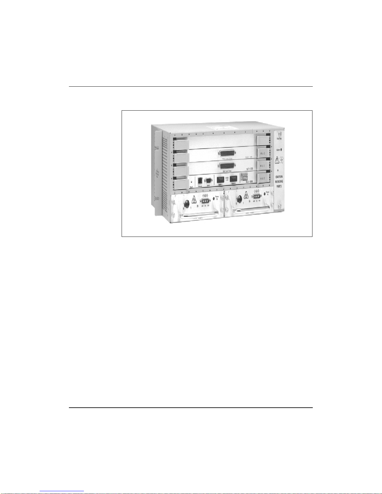
See “Passport 8250 device” (page 16) foranillustrationof the Passport 8250.
Passport 8250 Command Line Interface Guide R2.2
Page 16
16 Chapter 1 Introducing the Passport 8250
Figure 1
Passport 8250 device
Typical applications
Typical applications for the Passport 8250 include the following:
Benefits
241-5101-201 R2.2
• providing medium to high density DS-11/E1 ingress to an ATM carrier
network
• providing medium to high density DS-1/E1 ingress to an ATM wireless
network
• acting as a traffic bridge betweenATM and Time Division Multiplexing
(TDM) networks
The benefits of using the Passport 8250 include the following:
• protects existing equipment investments while migrating to ATM
• enhances network survivability and improves network reliability
• optimizes network utilization
• accommodates voice and data at high speeds and large volumes
• allows different services to be multiplexed on a common interface
Page 17

Main features
Management information bases (MIB)
Chapter 1 Introducing the Passport 8250 17
The main features of the Passport 8250 include the following:
• “Management information bases (MIB)” (page 17)
• “Circuit emulation services (CES)” (page 17)
• “Provisioning tools” (page 18)
• “Reference clock configuration” (page 20)
• “Constant bit rate (CBR) clocking” (page 20)
• “Fault management” (page 20)
• “Flash file system” (page 20)
The Passport 8250 supports the following management information bases:
• RFC 1595, SONET/SDH interface
• RFC 1406, DS-1 and E1 interface
• RFC 1695, ATM MIB
• ATMF CES MIB V.2, CES
• RFC 1213, MIB-II
• RFC 1573, IF interface MIB
• Enterprise MIB (proprietary)
For details on the MIBs that Passport 8250 supports, see “MIBs” (page 79).
Circuit emulation services (CES)
The Passport 8250 complies to ATM Forum CES-IS version 2.0 and supports
ATM adaptation layer (AAL1) constant bit rate (CBR) service for DS-1 and
E1 traffic.
The Passport 8250 supports unstructured and structured permanent virtual
circuit (PVC) connections. The structured connections consist of Basic and
CAS connections. For DS-1, the frames can be set to super frame (SF) or
extended super frame (ESF).
Passport 8250 Command Line Interface Guide R2.2
Page 18

18 Chapter 1 Introducing the Passport 8250
Provisioning tools
A combination of the following three tools are used to manage the Passport
8250 device and provision connections:
• “Command line interface” (page 18)
• “NMS Passport 8250 Tools” (page 19)
• “MIB browser” (page 20)
Command line interface
You can perform the followingactivitiesin the command line interface (CLI):
• create unstructured and structured connections using default values or
customized values for the following parameters:
— cell delay variation tolerance (CDVT)
— partial cell fill
— maximum buffer size
— CAS
— constant bit rate (CBR) clocking
• view connections
241-5101-201 R2.2
• delete all connections mapped to a port
• use default port configuration settings or customized values for the
following parameters:
— line type
— line coding
— signal mode
• configure the redundant ATM uplink port
• set the reference clock
• view the status of the boards
• Modify community strings
• check for network connectivity
• reboot the Passport 8250
Page 19

Chapter 1 Introducing the Passport 8250 19
• view faults in the fault log
• modify the boot parameters
• configure a VPI/VCI for IP over ATM (IPOA)
• load different versions of the system software and configuration data
NMS Passport 8250 Tools
The activities you can perform in the NMS Passport 8250 Tools depends on
the release number.
You can perform the following activities in the NMS Passport 8250 Tools
release 11.1:
• create unstructured and structured connections using default values or
customized values
• view connections
• delete connections
— structured connections can be deleted individually
• use default port configuration settings or customized values
• view the status of the boards and ports
• view ATM CES and DSX1 statistics
You can perform the following activities in the NMS Passport 8250 Tools
release 11.2:
• create unstructured and structured connections using default values or
customized values
• view connections
• delete connections
— structured connections can be deleted individually
• use default port configuration settings or customized values
• configure the redundant ATM uplink port
• set the reference clock
• view the status of the boards
Passport 8250 Command Line Interface Guide R2.2
Page 20

20 Chapter 1 Introducing the Passport 8250
• modify community strings
• view ATM CES and DSX1 statistics
• save and load templates
• register management workstations for traps
• start the surveillance of a Passport 8250 device
For details on the NMS Passport 8250 Tools, see NTP 241-6001-028, NMS
Passport 8250 Tools Guide.
MIB browser
You can use a third-party MIB browser to view the MIB objects.
Reference clock configuration
The clocking scheme can be derived from the Passport 8250 device or from
the ATM network off an external port on the Passport8250device.Whenthe
clock is derived from an external port, you can switch from the primary port
to the secondary port. For details on the clock configuration, see NTP 2415101-200, Passport 8250 Installation Guide.
Constant bit rate (CBR) clocking
For structured services, Passport 8250 supports synchronous CBR clocking.
For unstructured services, Passport 8250 supports synchronous and
synchronous residual time stamp (SRTS) CBRclocking. Differentports on a
single service board can use different clocking modes.
Fault management
Flash file system
241-5101-201 R2.2
The NetworkManagementSystem(NMS)isthe carrier domain management
system and it provides integrated fault management of Passport switches and
Passport 8250 multiplexers. For details on the NMS Advisor tools, See NTP
241-6001-011, NMS Advisor User Guide.
The Passport 8250 stores system software and configuration data in flash
memory.You can view the directory structure in the CLI and download new
system softwarethroughanetwork connection using FTP. Fordetailsonflash
memory, see “Flash file system” (page 65).
Page 21

Chapter 2
Getting started with the CLI
Thissectiondescribes the commandlineinterface (CLI) forthePassport 8250
device and provides instructions onhowto get started with the CLI. You can
view the following topics in this section:
• “Introducing the CLI” (page 21)
• “Accessing the CLI” (page 23)
• “Logging into the CLI” (page 23)
• “Changing the password” (page 24)
• “Accessing a board in the CLI” (page 24)
• “Getting help in the CLI” (page 25)
• “Logging out of the CLI” (page 26)
• “Restarting Passport 8250 device using the CLI” (page 26)
• “CLI commands” (page 27)
21
Introducing the CLI
The CLI is a terminal-based system used tomonitorandconfigure a Passport
8250 device. The CLI provides the following funcationality:
• Provision ports and connections.
• Manage the Passport 8250 device.
• Configure the CLI environment.
Passport 8250 Command Line Interface Guide R2.2
Page 22
22 Chapter 2 Getting started with the CLI
CLI screen
The CLIisauserinterface that enables you to manage aPassport8250 device
using a set of text commands. The commands are entered at a command line
prompt and the return key is used to execute the command. Depending on the
command entered, a system response is displayed. See “CLI screen”
(page 22) for an example of the CLI screen.
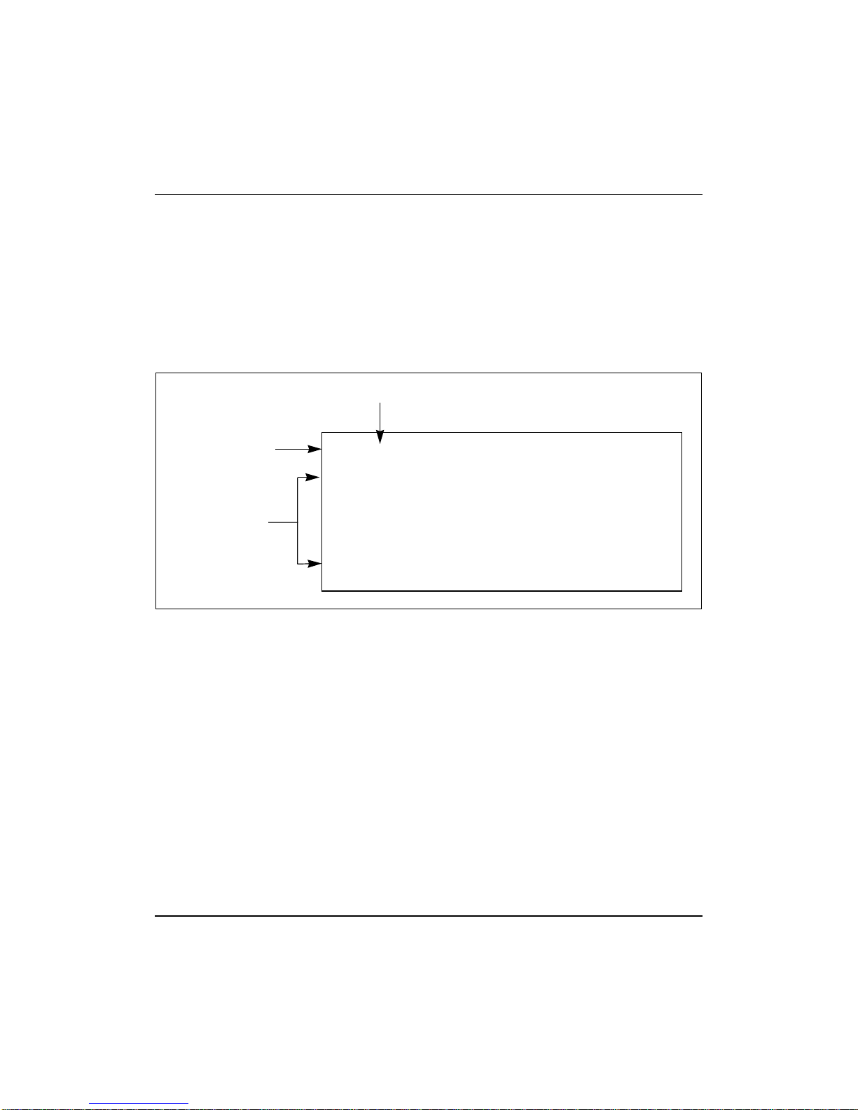
Figure 2
CLI screen
CLI text command
CLI prompt
System response
CLI prompt
[T1-2]: portconfig
1 LineType= ESF LineCoding= B8ZS SignalMode= NONE Status= 1
2 LineType= ESF LineCoding= B8ZS SignalMode= NONE Status= 1
3 LineType= ESF LineCoding= B8ZS SignalMode= NONE Status= 1
4 LineType= ESF LineCoding= B8ZS SignalMode= NONE Status= 1
5 LineType= ESF LineCoding= B8ZS SignalMode= NONE Status= 1
6 LineType= ESF LineCoding= B8ZS SignalMode= NONE Status= 1
7 LineType= ESF LineCoding= B8ZS SignalMode= NONE Status= 1
The CLI prompt comprises of the traffic interface and the slot of the board
number.
• Traffic interface.
• Board slot currently being accessed.
Whenyoufirstlog into theCLI,you do not accessaboard and theCLIprompt
is Edgeplex CLI. When you access a board, the Edgeplex CLI is no longer
available.
241-5101-201 R2.2
Page 23

Accessing the CLI
The Passport 8250 deviceisshippedwiththeCLIsoftware installed. Youcan
access the CLI from a terminalemulation devicethat is directly connected to
the Passport 8250 device, provided you are using a standard terminal
emultation software application. You can usethelocal host to directly access
the CLI before the Passport 8250 device is connected to the network.
You can also access the CLI from a terminal emulation device that is
connected to the same LAN segment or different LAN segment as the
Passport 8250 device, provided the Passport 8250 device already has an
Internetprotocol(IP)address. You canuseaTelnetsessionto remotely access
the CLIbyenteringthe IP address of the Passport8250device and Telnetport
23 telnet.
CLI priority
The CLI supports one CLI session at atimeand remote access to the CLI has
priority over direct access to the CLI. When a remote host overrides a CLI
session accessed from the local host, the local host is notified of the telnet
session to the CLIandtheCLIsessionishaulted until the telnet session to the
CLI is done.
Chapter 2 Getting started with the CLI 23
Logging into the CLI
The CLI sessions, Telnet sessions, and file transfer protocol (FTP) sessions
use the same username and password. The username is permanently set to
Admin and the password needs to be set the first time you log into the CLI.
To set the password, log into the CLI for the first time using the local host.
After this is done, you can Telnet to theCLI and FTP to the flash file system.
Note: If you forget the password, contact your Nortel Networks
representative to reset the password.
Procedure
1 If the username prompt is not displayed, press the return key.
2 At the username prompt, enter admin:
admin
3 At thepasswordprompt, enter a password between 8and 12 characters
in length.
Passport 8250 Command Line Interface Guide R2.2
Page 24

24 Chapter 2 Getting started with the CLI
Letters and numbers can be used.
Example
The following is an example of logging into the CLI for the first time and
setting the password to 1h6d833eR.
username: admin
password: 1h6d833eR
Changing the password
The passwd command changes the password.
Note: If you forget the password, contact your Nortel Networks
representative to reset the password.
1 Change the password:
passwd
Example
The following is an example of changing the password from 1h6d833eR to
jtF85dW4
[Edgeplex CLI]: passwd
enter current passwd: 1h6d833eR
please enter new password: jtF85dW4
confirm new password - please re-enter: jtF85dW4
password has been changed
Accessing a board in the CLI
You monitor and configure thePassport 8250 device by accessing the boards
on the Passport 8250 device. To access a specific board, type theslot number
for the board at the CLI prompt. The CLI prompt changes to display the
current board number.
For the boards availableonthePassport 8250 device and the slot numbers for
the board, see “Boards and slot numbers” (page 25).
241-5101-201 R2.2
Page 25

Chapter 2 Getting started with the CLI 25
Table 1
Boards and slot numbers
Board Slot number Displayed in CLI...
none none Edgeplex CLI
network board in slot 0 0 0
service board in slot 1 1 1
service board in slot 2 2 2
service board in slot 3 3 3
Procedure
1 At the CLI prompt, change to a new board number:
0|1|2|3
Example
The followingisanexampleof accessing a board for the first time. The board
is service board 2 and the traffic interface is T1.
[Edgeplex CLI]: 2
[T1-2]:
Getting help in the CLI
The CLI provides a help command to help you type the correct syntax for a
command. If you are unsure of the syntax of a command, type only as many
characters as is necessary to uniquely identify the command. The CLI will
attempt to match the characters to a valid command.
To know the syntax of all commands, type help at the CLI prompt. To know
the syntax for a particular command, type help and the command.
Procedure
1 Find the syntax for a CLI command.
help <CLI command>
Passport 8250 Command Line Interface Guide R2.2
Page 26

26 Chapter 2 Getting started with the CLI
Example
The following is an example of using the help commandtosee the syntax for
the mshow command.
[T1-2]: help mshow
mshow <port#i>[,<port#j>] [-detail]
Logging out of the CLI
To exit a CLI session, type exitattheCLIprompt.Thesystemwillnotifyyou
that are logged out of the CLI.
Procedure
1 Terminate the CLI session:
exit
Example
The following is an example of leaving a CLI session.
[T1-2]: exit
you have been logged off the CLI.
Info loggin to CLI console is set to on
Restarting Passport 8250 device using the CLI
Restart the Passport 8250 device using the reboot command.
The syntax of the command is:
reboot [net]
where
[net] restarts the Passport8250device and loads the system softwarefrom
the remote host entered in the host inet boot parameter. See NTP 241-5101200, Passport 8250 Installation Guide for information on the boot
parameters.
Note 1: Entering the reboot command without the [net] parameter
restarts the Passport 8250 and loads files from flash memory.
Note 2: After restarting the Passport 8250 device, you can log into the
CLI only after **** REBOOT COMPLETE, SYSTEM READY****is
displayed.
241-5101-201 R2.2
Page 27

Procedure
1 Restart the Passport 8250 device:
2 Confirm that you want to restart the Passport 8250 device:
Example
The following is an example of restarting the Passport 8250 device and
loading system software from the flash memory.
CLI commands
For a brief description of the commands available in the CLI, listed in
aphabetical order, see “CLI commands” (page 27).
Table 2
CLI commands
Chapter 2 Getting started with the CLI 27
reboot [net]
Reboot system from local load? (y/n) y
[E1-1]: reboot
Reboot system from local load? (y/n) y
rebooting system . . .
Command Where explained Description
0|1|2|3 “Accessing a board in the
CLI” (page 24)
alarm “Viewing alarm and
information messages”
(page 61)
bootconfig “Modifying boot
parameters” (page 60)
bootpath “Loading a different
software version”
(page 70)
card 0|1|2|3 “Accessing a board in the
CLI” (page 24)
(Sheet 1 of 3)
Access the network board in board slot 0 or the
service board in board slot 1, 2, or 3.
Enable or disable the display of the alarm
messages in the CLI. The default is off.
Display and modify the boot parameters.
Display and change the directory that Passport
8250 uses to load files during the boot-up
process.
Access the network board in board slot 0 or the
service board in board slot 1, 2, or 3.
Passport 8250 Command Line Interface Guide R2.2
Page 28

28 Chapter 2 Getting started with the CLI
Table 2 (continued)
CLI commands
Command Where explained Description
cd <directory path> “Flash file system
Change the directory in flash memory.
commands” (page 70)
clockconfig NTP 241-5101-200,
Passport 8250
Installation Guide
dir “Flash file system
commands” (page 70)
exit “Logging out of the CLI”
(page 26)
faultlogclear “Deleting entries in the
fault log” (page 64)
faultlogview “Viewing entries in the
fault log” (page 63)
help “Getting help in the CLI”
(page 25)
ibconfig “Configuring the ATM
uplink port for in-band
management” (page 54)
info on|off “Viewing alarm and
information messages”
(page 61)
map “Creating connections”
(page 37)
mshow “Searching by port
number” (page 46)
Display and configure the reference clock.
Display the files in the current directory in flash
memory.
Terminate a CLI session.
Delete the contents of the fault log.
View the entries in the fault log.
Display a list of the CLIcommandsor the syntax
of a specified CLI command.
Display and set the ATM uplink port for in-band
management.
Enable or disable the display of the information
messages in the CLI. The default is off.
Map connections to ports.
View ports with connections.
passwd “Changing the password”
(page 24)
ping <host IP> “Checking for network
connectivity” (page 53)
portconfig “Modifying port settings”
(page 33)
(Sheet 2 of 3)
241-5101-201 R2.2
Change the password.
See if a remote host is reachable.
Display and change the line type, line coding,
and signal mode for a port.
Page 29

Chapter 2 Getting started with the CLI 29
Table 2 (continued)
CLI commands
Command Where explained Description
pwd “Flash file system
commands” (page 70)
Display the current directory in the flash file
system.
reboot “Restarting Passport
8250 device using the
CLI” (page 26)
serial NTP 241-5101-200,
Passport 8250
Installation Guide
snmpcs “Modifyingthecommunity
strings” (page 60)
status “Viewing the status of the
boards” (page 64)
unmap “Deleting connections”
(page 50)
urconfig “Configuring the
redundant ATM uplink
port” (page 56)
ver “viewing the software
version” (page 65)
vshow “Searching by VPI or VPI/
VCI” (page 48)
(Sheet 3 of 3)
Command syntax
The CLI command syntax consists of the following components:
Reboot the Passport 8250 from flashmemoryor
from a remote host.
Display and set the baud rate for the serial port.
The default is 9600.
Display and set the SNMP community strings.
Display the status of the boards.
Delete connections mapped to ports.
Display and set the redundant ATM uplink port.
Display the software version running on the
Passport 8250.
View ports with connections.
• Command is the type of activity being performed.
— The command can be an abreviation for the activity. For example,
portconfig is an abbreviation for port configuration.
— A command can have more than one action. For example, you can
use the bootconfig command to display, and configure boot
parameters.
Passport 8250 Command Line Interface Guide R2.2
Page 30

30 Chapter 2 Getting started with the CLI
• Mandatory parameter is information that is required to complete the
command.
• Optional parameter is information that is required to perform a specific
action or information that is not required to complete the command.
— An optional parameter is identified by square brackets.
For example
bootconfig [set]
where
bootconfig is the command to configure the boot parameters.
[set] is an optional parameter to modify the boot parameters.
For details on the conventions used in this document, see “Conventions”
(page 12).
Abbreviations
The CLI command recognizes partial commands and parameters. Type only
as many characters as is necessary to uniquely identify the command or
parameter. For example, type clock for the clockconfig command.
Uppercase and lowercase
241-5101-201 R2.2
In general, the CLI does not distinguish between uppercase and lowercase
characters for commands, but does for valuesthatarestrings.Therefore,type
values that are string exactly as written in this document. For example, type
NONE or BITORIENTED for the signal mode parameter in the portconfig
Page 31

Chapter 3
Provisioning ports and connections
This section provides instructions on how to provision ports andconnections
using the CLI. You can view the following topics in this section:
• “Modifying port settings” (page 31)
• “Creating connections” (page 35)
• “Viewing connections mapped to ports” (page 45)
• “Deleting connections” (page 49)
Modifying port settings
The portconfig commandsets the line type, line coding, and signal mode for
DS-1/E1 ports on the service boards. See “Changing port configuration
settings” (page 33) and “Viewing port configuration settings” (page 33) for
information on the portconfig command. The syntax of the command is:
portconfig [<port#> [lineType=<value>]
[lineCoding=<value>] [SignalMode=<value>]]
31
where
<port#> is the port number
[lineType=<value>] is the line type for the port
[lineCoding=<value>] is the line coding for the port
[SignalMode=<value>] is the signal mode for the E1 port
Passport 8250 Command Line Interface Guide R2.2
Page 32

32 Chapter 3 Provisioning ports and connections
Note: Entering the portconfig command without the parameters displays
the existing line type, line coding, andsignal mode for all the ports on a
service board.
See “Portconfig command parameters” (page 32) for the values that the
Passport 8250 supports for line type, line coding, and signal mode.
Note: The values for the portconfig parameters are case sensitive.
Table 3
Portconfig command parameters
Connection Line type Line Coding SignalMode
unstructured E1
E1-CRC
structured Basic E1
E1-CRC
structured CAS E1
E1-CRC
unstructured D4
E1 traffic
DS-1 traffic
HDB3 NONE
HDB3 NONE
HDB3 BITORIENTED
B8ZS
not applicable
241-5101-201 R2.2
ESF
structured Basic D4
ESF
structured CAS SF D4 B8ZS
structured CAS ESF ESF B8ZS
AMI
B8ZS
AMI
AMI
AMI
not applicable
not applicable
not applicable
Page 33

Chapter 3 Provisioning ports and connections 33
Changing port configuration settings
Procedure
1 Ensure that you are accessing the correct service board number.
See “Accessing aboardintheCLI”(page 24) forinformationonchanging
board numbers.
2 Change the port configuration settings:
portconfig [<port#> [lineType=<value>]
[lineCoding=<value>][SignalMode=<value>]]
See Table 3 “Portconfig command parameters” (page 32) for the values
for the portconfig parameters.
Example
The following is an example of changing the signal mode on port 2, service
board 3 foranE1CASconnection. The signal mode changes from none to bit
oriented.
[Edgeplex CLI]: 3
[E1-3]: portconfig 2 signalMode=BITORIENTED
Viewing port configuration settings
The portconfig command usedwithout the parameters displays theline type,
line coding, signal mode, and statusfor all DS-1/E1 ports on a service board.
The status parameter is the alarm status for a port. See “Status command
parameter” (page 33) for the values for the status parameter.
Table 4
Status command parameter
Number Definition
1 No alarm present
2 Far end loss of frame (LOF)
4 Near end sending LOF indication
8 Far end sending alarm indication signal (AIS)
16 Near end sending AIS
(Sheet 1 of 2)
Passport 8250 Command Line Interface Guide R2.2
Page 34

34 Chapter 3 Provisioning ports and connections
Table 4 (continued)
Status command parameter
Number Definition
32 Near end LOF
64 Near end loss of signal (LOS)
128 Near end is looped
256 E1 TS16 AIS
512 Far end sending TS16 loss of multiple frames (LOMF)
1024 Near end sending TS16 LOMF
2048 Near end detects a test code
4096 Line status not defined
(Sheet 2 of 2)
Procedure
1 Ensure that you are accessing the correct service board number.
See “Accessing aboardintheCLI”(page 24) forinformationonchanging
board numbers.
2 View the port configuration settings for the ports on the service board:
241-5101-201 R2.2
portconfig
Example
The following is an example of displaying the existing port configuration
settings for all DS-1 ports on service board 2.
[Edgeplex CLI]: 2
[T1-2]: portconfig
1 LineType= ESF LineCoding= B8ZS SignalMode= NONE
Status= 1
2 LineType= ESF LineCoding= B8ZS SignalMode= NONE
Status= 1
3 LineType= ESF LineCoding= B8ZS SignalMode= NONE
Status= 1
4 LineType= ESF LineCoding= B8ZS SignalMode= NONE
Status= 1
Page 35

Chapter 3 Provisioning ports and connections 35
5 LineType= ESF LineCoding= B8ZS SignalMode= NONE
Status= 1
6 LineType= ESF LineCoding= B8ZS SignalMode= NONE
Status= 1
7 LineType= ESF LineCoding= B8ZS SignalMode= NONE
Status= 1
8 LineType= ESF LineCoding= B8ZS SignalMode= NONE
Status= 1
9 LineType= ESF LineCoding= B8ZS SignalMode= NONE
Status= 1
10 LineType= ESF LineCoding= B8ZS SignalMode= NONE
Status= 1
11 LineType= ESF LineCoding= B8ZS SignalMode= NONE
Status= 1
12 LineType= ESF LineCoding= B8ZS SignalMode= NONE
Status= 1
13 LineType= ESF LineCoding= B8ZS SignalMode= NONE
Status= 1
14 LineType= ESF LineCoding= B8ZS SignalMode= NONE
Status= 1
15 LineType= ESF LineCoding= B8ZS SignalMode= NONE
Status= 1
16 LineType= ESF LineCoding= B8ZS SignalMode= NONE
Status= 1
Creating connections
You can create unstructured connections, structured Basic connections, and
structured CAS connections using the CLI. Beforecreatingconnections, you
need to understand the rules for assigning virtual path identifiers (VPIs) and
virtual channel identifiers (VCIs), time slots, signal modes, and constant bit
rate (CBR) clocking. You also need to understand the syntax of the map
command. To understand the assignment rules and the syntax of the map
command, see the following sections before creating connections:
• “VPI/VCI assignments” (page 36)
• “Time slots” (page 36)
• “Signal mode” (page 36)
• “CBR clocking” (page 37)
• “Using the map command” (page 37)
Passport 8250 Command Line Interface Guide R2.2
Page 36

36 Chapter 3 Provisioning ports and connections
Once you have obtained the understanding required, see “Creating
unstructured connections” (page 41) and “Creating structured Basic and
structured CAS connections” (page 42) for the procedures to create
connections.
VPI/VCI assignments
The following rules apply for VPIs and VCIs:
• unique VPI/VCI pairing for each connection
• VPI number between 0 - 255
• VCI number between 0 - 65534
• do not use VPI 0/VCI 0
• do not use a VPI/VCI pairing that is reserved by the ATM Forum
standards
• do not use the VPI/VCI pairing used for in-band management
Time slots
The following rules apply for time slots:
• do not use time slot 0 for E1 structured Basic and structured CAS
connections
Signal mode
241-5101-201 R2.2
• do not use time slot 16 for E1 structured CAS connections
• enter the number of time slots assigned to a structured connection in a
hexadecimal format
— See “Time slots” (page 71) for information on converting time slots
to hexadecimal format
The following rules apply for signal mode:
• forE1 unstructuredandstructuredBasic connections,setthe signal mode
to none
• for E1 structured CAS connections, set the signal mode to bit oriented
Page 37

CBR clocking
The following rules apply for CBR clocking:
• SRTS CBR clocking is for DS-1/E1 unstructured services
• Synchronous CBR clocking is for DS-1/E1 unstructured and structured
services
• SRTS and synchronous CBR clock modes can be used for differentports
on a service board
Using the map command
The map command creates DS-1/E1 unstructured, structured Basic, and
structured CAS connections. The syntax of the command is:
map <port#i>[,<#j>] [<time slot>] <VPI#k> <VCI#l>
[cdvt=<value>] [PartialFill=<value>]
[MaxBuffSize=<value>] [CAS=<cas type>]
[cbrclock=<cbrClockMode>]
where
<port#i> is the first port number
[,<#j>] is the last port number in a range of port numbers
Chapter 3 Provisioning ports and connections 37
[<time slots>] is the bitmap of the assigned time slots for the
connection in hexadecimal format
<VPI#k> is the VPI number assigned to the ports
<VCI#l> is the VCI number assigned to the ports. The VCI number
increments by one for each port.
[cdvt=<value>] is the cell delay variation tolerance (cdvt) that Passport
8250 tolerates in the cell stream without producing errors on the CBR
interface. It is measured in 10 microsecond intervals.
[PartialFill=<value>] is the number of octets that is used in an ATM
cell before the ATM cell transmits onto the ATM network
Passport 8250 Command Line Interface Guide R2.2
Page 38

38 Chapter 3 Provisioning ports and connections
[MaxBuffSize=<value>] is the size of the buffer memory that Passport
8250 uses for storing the reassembled cell stream. It is measured in 10
microseconds.
[CAS=<cas type>] is the type of connection to map to the port
[cbrclock=<cbrClockMode>] is the CBR clock mode for the
connection.
See “Map command parameters” (page 38) for possible values for the map
command parameters.
For the default cdvt and MaxBuffSize values for DS-1/E1 structured Basic
and structured CAS connections, see “Cdvt and MaxBuffSize parameters
default values” (page 40).
Table 5
Map command parameters
Parameter Values
<port#i> 1 -16
[,<#j>] 2 -16
The [,<#j>] parameter must be greater than the <port#i>
parameter.
[<time slots>] See“Time slots”(page 71)forinformationon convertingtimeslots
to hexadecimal.
<VPI#k> 0 - 255
See “VPI/VCI assignments” (page 36) for the rules on using VPI
numbers.
<VCI#l> 0 - 65534
For multiple ports, the first port is assigned the VCI number and
the VCI increments by one for each subsequent port.
See “VPI/VCI assignments” (page 36) for the rules on using VCI
numbers.
(Sheet 1 of 3)
241-5101-201 R2.2
Page 39

Chapter 3 Provisioning ports and connections 39
Table 5 (continued)
Map command parameters
Parameter Values
[cdvt=<value>] For DS-1/E1 unstructured connections, the default value is 100.
See Table 6 “Cdvt and MaxBuffSize parameters default values”
(page 40) for the default values for structured connections.
Note:
This document doesnot explain how to modifythe default
value and we recommend that you do not change the default
value.
[PartialFill=<value>] PartialFill is only used for structured Basic and structured CAS
connections. The default is 0 (zero) for no partial cell fill.
Note 1:
The PartialFill parameter has to be greater than the
number of time slots assigned to a connection.
Note 2:
Thisdocumentdoesnot explainhowtomodify the default
value and we recommend that you do not change the default
value.
[MaxBuffSize=<value>] For DS-1/E1 unstructured connections, the default value is 225
See Table 6 “Cdvt and MaxBuffSize parameters default values”
(page 40) for the default values for structured connections.
Note 1:
The MaxBuffSize parameter has to be at least twice the
value of the cdvt parameter.
Note 2:
Thisdocumentdoesnot explainhowtomodify the default
value and we recommend that you do not change the default
value.
(Sheet 2 of 3)
Passport 8250 Command Line Interface Guide R2.2
Page 40

40 Chapter 3 Provisioning ports and connections
Table 5 (continued)
Map command parameters
Parameter Values
[CAS=<cas type>] The CAS parameter is used for structured Basic and structured
CAS connections. The default is BASIC.
BASIC = structured Basic connection
E1 = structured E1 CAS connection
DS1_SF =structuredDS-1CASconnection with super frame (SF)
DS1_ESF = structured DS-1 CAS connection with extended
super frame (ESF)
J2 = not supported
Note:
The values are case sensitive.
[cbrclock=<cbrClockMode>] The cbrClock parameter is used for unstructured connections.
Structured connections use synchronous CBR clocking.
SYNCHRONOUS = synchronous CBR clocking. Default.
SRTS = synchronous residual time stamp CBR clocking.
Note:
The values are case sensitive.
(Sheet 3 of 3)
241-5101-201 R2.2
Table 6
Cdvt and MaxBuffSize parameters default values
# of time slots cdvt MaxBuffSize
1 650 1875
2 350 1000
3 250 725
4 200 550
5 175 475
6 150 400
7 125 300
8,9 100 300
10,11 100 275
(Sheet 1 of 2)
Page 41

Chapter 3 Provisioning ports and connections 41
Table 6 (continued)
Cdvt and MaxBuffSize parameters default values
# of time slots cdvt MaxBuffSize
12 to 15 100 250
16 to 23 100 225
24 to 32 100 200
(Sheet 2 of 2)
Creating unstructured connections
Procedure
1 For E1, ensure that the value for the signal mode is none.
See “Modifying port settings” (page 31) for information on the signal
mode.
2 Ensure that you are accessing the correct board number.
See “Accessing aboardintheCLI”(page 24) forinformationonchanging
board numbers.
3 Choose the ports to map to the connections.
4 Choose the constant bit rate (CBR) clock mode.
5 Create the unstructured connections:
map <port#i>[,<#j>] <VPI#k> <VCI#l>
[cbrclock=<cbrClockMode>]
6 Verify that the connections were created and the CBR clock mode is set
correctly:
mshow [<port#>[,<#j>]] -detail
See “Searching by port number” (page 45)forinformation on the mshow
command.
Example
The following is an example of creating a DS-1 unstructured connection on a
single port. VPI 10 and VCI 11 are assigned to the connection. The
connection is mapped to port 1 on service board 1. The default CBR clocking
is used. The mshow command is used to verify that the connection was
created.
[Edgeplex CLI]: 1
Passport 8250 Command Line Interface Guide R2.2
Page 42

42 Chapter 3 Provisioning ports and connections
[T1-1]: map 1 10 11
[T1-1]: mshow 1
vpi=10 vci=11 --> card=1 port=1
Example
The following is an example of creating DS-1 unstructured connections on
multiple ports. VPI 11 and VCI 100, 101 and 102 are assigned to the
connections. The connections are mapped to ports 10, 11, and 12 on service
board 1. The CBR clock mode is SRTS. The mshow command is used to
verify that the connections were created and the CBR clocking is set to SRTS.
[Edgeplex CLI]: 1
[T1-1]: map 10,12 11 100 cbrclock=SRTS
[T1-1]: mshow 10,12 -detail
vpi=11 vci=100 --> card=1 port=10 cdvt=100
MaxBuffSz=225 PartFill=0 CAS=BASIC cbrClock=SRTS
vpi=11 vci=101 --> card=1 port=11 cdvt=100
MaxBuffSz=225 PartFill=0 CAS=BASIC cbrClock=SRTS
vpi=11 vci=102 --> card=1 port=12 cdvt=100
MaxBuffSz=225 PartFill=0 CAS=BASIC cbrClock=SRTS
Creating structured Basic and structured CAS connections
241-5101-201 R2.2
Procedure
1 Choose the type of connection you want to create.
See “Using the map command” (page 37) for information on structured
connections and the CAS parameter.
2 For E1, ensure that the value for the signal mode is set properly.
See “Modifying port settings” (page 31) for information on the signal
mode.
3 Ensure that you are accessing the correct service board number.
See “Accessing aboardintheCLI”(page 24) forinformationonchanging
board numbers.
4 Choose the ports to map to the connections.
5 Choose the time slots to assign to the connection and convert the time
slots into hexadecimal format.
Page 43

Chapter 3 Provisioning ports and connections 43
See “Converting time slots to hexadecimal format” (page 71) for
information on converting the number of time slots into hexadecimal
format.
See “Time slots” (page 36) for the rules for using time slots.
6 Create the structured connections:
map <port#i>[,<#j>] [<time slots>] <VPI#k> <VCI#l>
[CAS=<cas type>]
7 Verify that the connections were created:
mshow [<port#>[,<#j>]]
Example
The following is an example of creating a DS-1 structured Basic connection
for a single port. Time slot 1, VPI 200, and VCI 30 are assigned to the
connection. The connection is mapped to port 6 on service board 2. The
mshow command is used to verify that the connection was created.
[Edgeplex CLI]: 2
[T1-2]: map 6 0x000002 200 30 CAS=BASIC
[T1-2]: mshow 6
vpi=200 vci=30 --> card=2 port=6 channel(s)=0x00000002
Example
The following is an example of creating E1 structured Basic connections for
multiple ports. All E1 time slots, except 0 and 16, are assigned to the
connections. VPI 18 and VCI 10, 11, 12, and 13 are assigned to the
connections. The connections are mapped to ports 1, 2, 3, and 4 on service
board 2. The mshow command is used to verify that the connections were
created.
[Edgeplex CLI]: 2
[E1-2]: map 1,4 0xFFFEFFFE 18 10 CAS=BASIC
[E1-2]: mshow 1,4
vpi=18 vci=10 -> card=2 port=1 channel(s)=0xfffefffe
vpi=18 vci=11 -> card=2 port=2 channel(s)=0xfffefffe
vpi=18 vci=12 -> card=2 port=3 channel(s)=0xfffefffe
vpi=18 vci=13 -> card=2 port=4 channel(s)=0xfffefffe
Passport 8250 Command Line Interface Guide R2.2
Page 44

44 Chapter 3 Provisioning ports and connections
Example
The following is an example of creating an E1 CAS connection for a single
port. Time slots 1, 2, and 3 are assigned to the connection. VPI 18 and VCI
900 are assigned to the connection. The connection is mapped to port 1 on
service board 1. The mshow command is used to verify that the connection
was created.
[Edgeplex CLI]: 1
[E1-1]: map 1 0x0000000E 18 900 CAS=E1
[E1-1]: mshow 1
vpi=18 vci=900 ->card=1 port=1 channel(s)=0x000000000e
Example
The following is an example of creating E1 CAS connections for multiple
ports. Time slots 1 to 15 are assigned to the connections.VPI20 and VCI 50,
51, and 52 are assigned to the connections. The connections are mapped to
ports 10, 11, and 12 on service board 2. The mshow command is used to
verify that the connections were created.
[Edgeplex CLI]: 2
[E1-2]: map 10,12 0x0000FFFE 20 50 CAS=E1
241-5101-201 R2.2
[E1-2]: mshow 10,12
vpi=20 vci=50 -> card=2 port=10 channel(s)=0x0000fffe
vpi=20 vci=51 -> card=2 port=11 channel(s)=0x0000fffe
vpi=20 vci=52 -> card=2 port=12 channel(s)=0x0000fffe
Example
The following is an example of creating a DS-1 CAS connection with
extended super frame (ESF) for a single port. All 24 time slots are assigned
to the connection. VPI 200 and VCI 30 are assigned to the connection. The
connection is mapped to port 6 on service board 2. The mshow command is
used to verify that the connection was created.
[Edgeplex CLI]: 2
[T1-2]: map 6 0xFFFFFF 200 30 CAS=DS1_ESF
[T1-2]: mshow 6
vpi=200 vci=30 --> card=2 port=6 channel(s)=0x00ffffff
Page 45

Chapter 3 Provisioning ports and connections 45
Example
The following is an example of creating DS-1 CAS connections with super
frame (SF) for multiple ports. Time slots 0 and 1 are assigned to the
connections. VPI 200 and VCI 900 are assigned to the connections. The
connections are mapped to ports 1, 2, and 3 on service board 2. The mshow
command is used to verify that the connections were created.
[Edgeplex CLI]: 2
[T1-2]: map 1,3 0x000003 200 900 CAS=DS1_SF
[T1-2]: mshow 1,3
vpi=200 vci=900 -> card=2 port=1 channel(s)=0x00000003
vpi=200 vci=901 -> card=2 port=2 channel(s)=0x00000003
vpi=200 vci=902 -> card=2 port=3 channel(s)=0x00000003
Viewing connections mapped to ports
There are two ways toviewconnections mapped to ports usingthe CLI. You
can view connections by “Searching by port number” (page 45) and
“Searching by VPI or VPI/VCI” (page 47).
Searching by port number
The mshow command enables you to search for ports with mapped
connections. The syntax of the command is:
mshow [<port#i>[,<#j>]] [-detail]
where
[<port#i>] is the first port number
[,<#j>] is the last port number in a range of port numbers
[-detail] displays the VPI, VCI, time slots, cdvt, MaxBuffSize,
PartialFill, CAS, and CBR clock mode
Note: Entering the mshow command without the parameters displays all
ports on a service board with connections.
Procedure
1 Ensure that you are accessing the correct service board number.
See “Accessing aboardintheCLI”(page 24) forinformationonchanging
board numbers.
Passport 8250 Command Line Interface Guide R2.2
Page 46

46 Chapter 3 Provisioning ports and connections
2 Search for ports with connections:
mshow [<port#i>[,<#j>] [-detail]]
Example
The following is an example of displaying the VPI number, VCI number,
board number, port number, number of time slots, cell delay variation
tolerance (cdvt), partial cell fill, maximum buffer size, CAS type, and CBR
clocking forstructuredconnectionsmappedto ports 10, 11, and 12 onservice
board 2.
[Edgeplex CLI]: 2
[E1-2]: mshow 10,12 -detail
vpi=20 vci=50 --> card=2 port=10 channel(s)=0x0000fffe
cdvt=100 MaxBuffSz=250 PartFill=0 CAS=E1
cbrClock=SYNCHRONOUS
vpi=20 vci=51 --> card=2 port=11 channel(s)=0x0000fffe
cdvt=100 MaxBuffSz=250 PartFill=0 CAS=E1
cbrClock=SYNCHRONOUS
vpi=20 vci=52 --> card=2 port=12 channel(s)=0x0000fffe
cdvt=100 MaxBuffSz=250 PartFill=0 CAS=E1
cbrClock=SYNCHRONOUS
241-5101-201 R2.2
Example
The following is an example of displaying the VPI number, VCI number,
board number, and port number for the connections mapped to all the ports
on service board 3.
[Edgeplex CLI]: 3
[T1-3] : mshow
vpi=15 vci=101 --> card=3 port=1
vpi=15 vci=102 --> card=3 port=2
vpi=15 vci=103 --> card=3 port=3
vpi=15 vci=104 --> card=3 port=4
vpi=15 vci=105 --> card=3 port=5
vpi=15 vci=106 --> card=3 port=6
vpi=15 vci=107 --> card=3 port=7
vpi=15 vci=108 --> card=3 port=8
vpi=15 vci=109 --> card=3 port=9
vpi=15 vci=110 --> card=3 port=10
Page 47

Chapter 3 Provisioning ports and connections 47
vpi=15 vci=111 --> card=3 port=11
vpi=15 vci=112 --> card=3 port=12
vpi=15 vci=113 --> card=3 port=13
vpi=15 vci=114 --> card=3 port=14
vpi=15 vci=115 --> card=3 port=15
vpi=15 vci=116 --> card=3 port=16
Searching by VPI or VPI/VCI
The vshow command enables you to search for connections with a VPI
number or VPI and VCI pairing. The syntax of the command is:
vshow [<VPI#i>[,<#j>] [<VCI#k>[,<#l>]] [-detail]]
where
<VPI#i> is the first VPI number
[,<#j>] is the last VPI number in a range of VPI numbers
<VCI#k> is the first VCI number
[,<#l>] is the last VCI number in a range of VCI numbers
[-detail] displays the board number, port number, cdvt, MaxBuffSize,
PartialFill, CAS, and CBR clock mode
Note: Entering thevshow command without the parameters displays all
connections mapped to ports.
Searching by VPI number
Procedure
1 Search for connections with the VPI numbers:
vshow [<VPI#i>[,<#j>] [-detail]
Example
The following is an example of displaying the VPI number, VCI number,
board number, port number, number of time slots, cell delay variation
tolerance (cdvt), partial cell fill, maximum buffer size, CAS type, and CBR
clocking for structured connections using VPI 20 on service board 2.
[Edgeplex CLI]: 2
[E1-2]: vshow 20 -detail
Passport 8250 Command Line Interface Guide R2.2
Page 48

48 Chapter 3 Provisioning ports and connections
vpi=20 vci=50 --> card=2 port=10 channel(s)=0x0000fffe
cdvt=100 MaxBuffSz=250 PartFill=0 CAS=E1
cbrClock=SYNCHRONOUS
vpi=20 vci=51 --> card=2 port=11 channel(s)=0x0000fffe
cdvt=100 MaxBuffSz=250 PartFill=0 CAS=E1
cbrClock=SYNCHRONOUS
vpi=20 vci=52 --> card=2 port=12 channel(s)=0x0000fffe
cdvt=100 MaxBuffSz=250 PartFill=0 CAS=E1
cbrClock=SYNCHRONOUS
Searching by VPI number and VCI number
Procedure
1 Search for connections with VPI numbers and VCI numbers:
vshow [<VPI#i>[,<#j>] [<VCI#k>[,<#l>]] [-detail]]
Example
The following is an example of displaying the VPI number, VCI number,
board number, and port number for connections using VPI 250 and VCI 60,
61, or 62 on service board 3.
[Edgeplex CLI]: 3
[T1-3] : vshow 250 60,62
241-5101-201 R2.2
VPI=250 VCI=60 --> card=3 port=1
VPI=250 VCI=61 --> card=3 port=2
VPI=250 VCI=62 --> card=3 port=3
Example
The following is an example of displaying the VPI number, VCI number,
board number, port number, and number of time slots for connections using
VPI 9 or 10 and VCI 1 or 2 on service board 2.
[Edgeplex CLI]: 2
[T1-2]: vshow 9,10 1,2
vpi=9 vci=1 --> card=2 port=1 channel(s)=0x00ffffff
vpi=10 vci=2 --> card=2 port=2 channels(s)=0x00ffffff
Searching for all connections mapped to ports
Procedure
1 Search for all connections mapped to ports on a service board number:
Page 49

Chapter 3 Provisioning ports and connections 49
vshow
Example
The following is an example of displaying the VPI number, VCI number,
board number, and port number for connections on service board 3.
[Edgeplex CLI]: 3
[T1-3] : vshow
vpi=15 vci=101 --> card=3 port=1
vpi=15 vci=102 --> card=3 port=2
vpi=15 vci=103 --> card=3 port=3
vpi=15 vci=104 --> card=3 port=4
vpi=15 vci=105 --> card=3 port=5
vpi=15 vci=106 --> card=3 port=6
vpi=15 vci=107 --> card=3 port=7
vpi=15 vci=108 --> card=3 port=8
vpi=15 vci=109 --> card=3 port=9
vpi=15 vci=110 --> card=3 port=10
vpi=15 vci=111 --> card=3 port=11
vpi=15 vci=112 --> card=3 port=12
vpi=15 vci=113 --> card=3 port=13
vpi=15 vci=114 --> card=3 port=14
vpi=15 vci=115 --> card=3 port=15
vpi=15 vci=116 --> card=3 port=16
Deleting connections
The unmap command deletes connections mapped toports.Thesyntaxofthe
command is:
unmap <port#i>[,<#j>]
where
<port#i> is the first port number
[,<#j>] is the last port number in a range of port numbers
Procedure
1 Ensure that you are accessing the correct service board number.
See “Accessing aboardintheCLI”(page 24) forinformationonchanging
board numbers.
Passport 8250 Command Line Interface Guide R2.2
Page 50

50 Chapter 3 Provisioning ports and connections
2 Verify that the connections exist:
mshow [<port#i>[,<#j>]
3 Delete the connections:
unmap <port#i>[,<#j>]
Example
The following is an example of unmapping the connections mapped to ports
10, 11, and 12 on service board 2. Before unmapping the connections, the
mshow command is used to verify that the connections exist.
[Edgeplex CLI]: 2
[E1-2]: mshow 10,12
vpi=20 vci=50 -> card=2 port=10 channel(s)=0x0000fffe
vpi=20 vci=51 -> card=2 port=11 channel(s)=0x0000fffe
vpi=20 vci=52 -> card=2 port=12 channel(s)=0x0000fffe
[E1-2]: unmap 10,12
unmapped port 10 channel(s)=0x0000fffe from vpi=20
vci=50
unmapped port 11 channel(s)=0x0000fffe from vpi=20
vci=51
unmapped port 12 channel(s)=0x0000fffe from vpi=20
vci=52
241-5101-201 R2.2
Example
The following is an example of unmapping the connections to port 6 on
service board 2. Before unmapping the connection, the mshow command is
used to verify that the connection exists.
[Edgeplex CLI]: 2
[T1-2]: mshow 6
vpi=200 vci=30 --> card=2 port=6 channel(s)=0x00ffffff
[T1-2] : unmap 6
unmapped port 6 from vpi=200 vci=30
Page 51

Chapter 4
Other activities in the CLI
This section providesinstructionsonhowtoperformactivities not covered in
the previous two sections. You can view the following topics in this section:
• “Checking for network connectivity” (page 51)
• “Configuring the ATM uplink port for in-band management” (page 52)
• “Configuring the redundant ATM uplink port” (page 54)
• “Modifying boot parameters” (page 58)
• “Modifying the community strings” (page 58)
• “Viewing alarm and information messages” (page 59)
• “Viewing faults in the fault log” (page 60)
• “Viewing system information” (page 62)
Checking for network connectivity
The ping command tests that a remote host is reachable from the Passport
8250 device by sending Internet Control Message Protocol (ICMP) echo
request packets. The syntax of the command is:
51
where
<host IP> is the IP address of the remote host
ping <hostIP> [<numPktsToRx>]
Passport 8250 Command Line Interface Guide R2.2
Page 52

52 Chapter 4 Other activities in the CLI
[<numPktsToRx>] is the number of ICMP packets that the Passport 8250
devicereceivesfrom the remotehost. Ifthe numberof packets is unspecified,
the routine waits for only one echo reply packet. If no packets are received
within 5 seconds, the Passport 8250 displays thatthere is no answer from the
remote host and exits the ping command.
Procedure
1 Test that a remote host is reachable from the Passport 8250 device:
ping <hostIP> [<numPktsToRx>]
Example
The followingisanexampleofsendingaICMP echo request packet from the
Passport 8250 devicetoaremotehost at IP address 192.0.0.20 and asking for
the remote host to send one ICMP packet back to the Passport 8250 device.
[Edgeplex CLI]: ping 192.0.0.20 1
Configuring the ATM uplink port for in-band management
The ibconfig command configures the ATM uplink port for in-band
management. The syntax of the command is:
ibconfig [set]
241-5101-201 R2.2
where
[set] configures the ATM uplink port for in-band management
Note: Entering the ibconfig command without the [set] parameter
displays the current in-band configuration parameters.
Page 53

Chapter 4 Other activities in the CLI 53
For details on the ibconfig parameters, see “Ibconfig command parameters”
(page 53).
Table 7
Ibconfig command parameters
Parameter Definition
vpi The virtual path identifier (VPI) number assigned to in-band
management over the ATM uplink port.
See“VPI/VCIassignments” (page 36)for theruleson using VPI
numbers.
vci The virtual channel identifier (VCI) number assigned to in-band
management over the ATM uplink port.
See “VPI/VCI assignments” (page 36) for the rules on using
VCI numbers.
ip The IP address and subnet mask of the Passport 8250 device
denoted as <IP address>:<subnet mask>.
The network portionof the in-band IP address is differentfrom
the network portion of the ethernet IP address.
See NTP 241-5101-200,
information on the boot parameters.
enabled Enableordisablein-bandmanagement on the ATMuplinkport.
Accepted values are yes or no. The default value is no.
Note:
If the enabled parameter is set to no while connected
through the in-band, the TELNET session to the CLI is
terminated. After five minutes, you can log into the CLI again
through the serial port or a TELNET session over the ethernet
port.
Passport 8250 Installation Guide
for
Procedure
1 Configure the ATM uplink port for in-band management:
ibconfig [set]
2 For the vpi parameter, enter a VPI number.
3 For the vci parameter, enter a VCI number.
4 For the ip parameter, enter the IP address of the Passport 8250 and the
subnet mask.
Passport 8250 Command Line Interface Guide R2.2
Page 54

54 Chapter 4 Other activities in the CLI
5 For the enabled parameter,enteryestoenablethein-bandmanagement.
6 Verify that the ATM port is configured for in-band management:
ibconfig
Example
The following is an exampleof configuring the ATM uplink port for in-band
management for the first time. VPI 100, VCI 50, and IP address and subnet
mask 47.22.209.108:FFFFFF00areused.After the ATM uplink port issetfor
in-band management, the ibconfig command without the [set] parameter is
used to verify the ibconfig parameters.
[Edgeplex CLI]:ibconfig set
vpi: 0 100
vci: 0 50
ip: 0.0.0.0:0.0 47.22.209.108:FFFFFF00
enabled: no yes
[Edgeplex CLI]: ibconfig
VPI: 100
VPI: 50
ip: 47.22.209.108:FFFFFF00
enabled: yes
Configuring the redundant ATM uplink port
Using the urconfig command, you configure the redundant ATM uplink port
by selecting a primary port and a switching method when the signalisloston
the primary port and a signal is detected onthesecondaryport.The syntax of
the command is:
urconfig [set]
where
[set] configures the redundant ATM uplink port
Note: Entering the urconfig command without the [set] parameter
displays the existing urconfig parameters.
See “Urconfig command parameters” (page 55) for information on the
urconfig parameters.
241-5101-201 R2.2
Page 55

Chapter 4 Other activities in the CLI 55
The switching method options are automatic switching and manual
switching. For automatic switching, the Passport 8250 changes from the
primary port to the secondary port. For details on automatic switching, see
“Configuring the redundant ATM uplink port for automatic switching”
(page 55).
For manual switching, you use the urconfig command to change from the
primary port to the secondary port. For details on manual switching, see
“Configuring the redundant ATM uplink port for manual switching”
(page 57).
Table 8
Urconfig command parameters
Parameter Definition
automatic
switching
The switching method.
on = automatic switching is enabled. The Passport 8250
device switches from the primary port to the secondary port
when the signal is lost on the primary port and a signal is
present on thesecondaryport.Theactiveportandtheprimary
port parameters can not be modified.
off = default = automatic switching is disabled. You use the
urconfig command to change from the primary port to the
secondary port.
active port The port currently used to listen for incoming signals.
A = ATM uplink port A. Default.
B = ATM uplink port B
primary
port
The port selected as the primary port. The other port is
automatically designated as the secondary port.
A = ATM uplink port A. Default.
B = ATM uplink port B
Configuring the redundant ATM uplink port for automatic
switching
Note: Set the active port and primary port parameters to the same port
before setting the automatic switching parameter to on.
Passport 8250 Command Line Interface Guide R2.2
Page 56

56 Chapter 4 Other activities in the CLI
Procedure
1 Display the urconfig parameters to set the active port and primary port
parameters:
urconfig [set]
automatic switching: off
active port: A
primary port: A
2 For the automatic switching parameter, press enter to move to the next
parameter.
3 For the active port parameter, enter B or press enter to accept port A.
4 For the primary port parameter, enter B or press enter to accept port A.
5 Display the urconfigparameterstosetthe automatic switching parameter:
urconfig [set]
6 For the automatic switching parameter, enter on:
7 For the active port field, press enter to move to the next parameter:
8 For the primary port field, press enter to move to the next parameter:
9 Verify the new settings:
urconfig
241-5101-201 R2.2
Example
The following is an example of configuring the redundant ATM uplink port
for automatic switching. The primary port and active port is port B. After
configuring the ATM uplink port, the urconfig command without the [set]
parameter is used to verify the urconfig parameters.
[Edgeplex CLI]: urconfig set
automatic switching: off
active port: A B
primary port: A B
[Edgeplex CLI]:urconfig set
automatic switching: off on
active port: B
primary port: B
[Edgeplex CLI]: urconfig
Page 57

Chapter 4 Other activities in the CLI 57
automatic switching: on
active port: B
primary port: B
Configuring the redundant ATM uplink port for manual
switching
Procedure
1 Display the urconfig parameters to set the active port and primary port
parameters:
urconfig [set]
automatic switching: off
active port: A
primary port: A
2 For the automatic switching parameter, press enter to move to the next
parameter.
3 For the active port parameter, enter B or press enter to accept A.
4 For the primary port parameter, enter B or press enter to accept A.
5 Verify the settings:
urconfig
Example
The following is an example of configuring the redundant ATM uplink port
for manual switching. The primary port and active port is port B. After
configuring the ATM uplink port, the urconfig command is used without the
[set] parameter to verify the urconfig parameters.
[Edgeplex CLI]: urconfig set
automatic switching: off
active port: A B
primary port: A B
[Edgeplex CLI]: urconfig
automatic switching: off
active port: B
primary port: B
Passport 8250 Command Line Interface Guide R2.2
Page 58

58 Chapter 4 Other activities in the CLI
Modifying boot parameters
The bootconfig command modifies the boot parameters. For details on the
boot parameters, see NTP 241-5101-200, Passport 8250 Installation Guide.
The syntax of the command is:
bootconfig [set]
where
[set] changes the boot parameters
Note: Entering the bootconfig command without the [set] parameter
displays the current boot parameters.
Modifying the community strings
The snmpcs command modifies the get, set, and trap community strings for
Simple Network Management Protocol (SNMP) operations between the
Passport 8250 device and the network manager. The syntax of the command
is:
snmpcs [set]
where
241-5101-201 R2.2
[set] modifies the community strings. For the get and trap community
strings, the default value is public. For the set community string, the default
value is private.
Note: Entering the snmpcs command without the [set] command
displays the existing community strings.
Procedure
1 Set the community strings:
snmpcs [set]
Enter new value(s) beside the old one(s). Enter a ‘.’
to clear a value
GET = public
SET = private
TRAP = public
2 For the GETcommunity string, press enterto accept the default value or
enter private.
Page 59

Chapter 4 Other activities in the CLI 59
3 For the SET community string, press enter to acceptthe default value or
enter public.
4 For the TRAPcommunitystring,pressenterto accept the default valueor
enter private.
5 Verify the new settings:
snmpcs
Note:
EnsurethatthePassport 8250 community stringsaresetthesame
as the network manager community strings.
Example
The following is an example of changing the set community string from
private to public. After modifying the set community string, the snmpcs
command is used without the [set] parameter to verify the community strings.
[Edgeplex CLI]: snmpcs set
Enter new value(s) beside the old one(s). Enter a ‘.’
to clear a value
GET = public
SET = private public
TRAP = public
[Edgeplex CLI]: snmpcs
GET = public
SET = public
TRAP = public
Viewing alarm and information messages
Use the alarm and info commands to enable and disable alarm and
information messages in the CLI. See “Alarm and information messages”
(page 60) for the type of information that can be given in a message. The
default for both commands is off. The syntax of the alarm command is:
alarm on|off
where
<on|off> turns the display of the alarm messages on or off
The syntax of the info command is:
info on|off
Passport 8250 Command Line Interface Guide R2.2
Page 60

60 Chapter 4 Other activities in the CLI
where
on|off turns the display of the information messages on or off
Note: We recommend that you disable the display of the alarm and
information messages in the CLI and use the fault and information
messages ports.
Table 9
Alarm and information messages
Type Definition
eventID unique identification number
service Type of service. The options are ethernet,ATM,
category The category of the message. The options are
card The card orlocation of where the eventoccurred
module The module or location of where the event
or DS-1/E1.
information message or alarm message
occurred
Note 1: The Passport 8250 may reboot when there is a hardware fault,
software fault, or non-responding service board.
Note 2: The alarm messages do not have time stamps.
Viewing faults in the fault log
The Passport 8250 records faults that interfere with the performance of the
Passport 8250 device in the fault log file. The fault log contains a maximum
of 24 entries, with the most recent fault as entry number one. Nortel support
uses the information to help identify the cause of the problems.
Note: When a fault is recorded in the fault log, the amber LED on the
network card is activated. The LED turns off when the fault log is
cleared.
241-5101-201 R2.2
Page 61

Viewing entries in the fault log
The faultlogview command displays entries in the fault log.The syntax of the
command is:
faultlogview [<entry#>]
where
[<entry#>] is an entry number between 1 and 24 in the fault log
Note: Entering the faultlogview command without the [<entry#>]
parameter displays all the fault log entries.
Procedure
1 Display the entries in the fault log:
faultlogview [<entry#>]
Example
The following is an example of displaying the entries in the fault log. There
are three entries.
[Edgeplex CLI]: faultlogview
Entry 1: TimeStamp (0d: 0h: 1m:11s), Board (1), Fault
Id (7)
Entry 2: TimeStamp (0d: 0h: 0m: 0s), Board (1),
Machine Check
Entry 3: TimeStamp (0d: 0h: 3m:10s), Board (1), Fault
Id (4)
Chapter 4 Other activities in the CLI 61
Example
The following is an example of displaying the most recent fault that was
generated from the system.
[Edgeplex CLI]: faultlogview 1
Entry # : 1
Time stamp : 0d: 0h: 0m: 0s
Board # : 1
Machine check exception number : 512
Offending task : "tWdbTask"
Program counter register : 0x000fa3a8
Data access register : 0x203e6f14
Data storage interrupt status register : 0x0001812b
Machine status register : 0x00009020
Passport 8250 Command Line Interface Guide R2.2
Page 62

62 Chapter 4 Other activities in the CLI
Link register : 0x000fa37c
Count register : 0x00000000
Condition register : 0x22000000
Fixed point exception register : 0x20000000
Stack pointer register : 0x003e6f10
Deleting entries in the fault log
The faultlogclear command deletes all the entries in the fault log.
Note: Werecommend that you do not remove the entries in thefault log
until Nortel support knows the cause of the faults.
Procedure
1 Delete the entries in the fault log:
faultlogclear
Example
The following is an example of deleting the entries in the fault log.
[Edgeplex CLI]: faultlogclear
The fault log has been cleared
Viewing system information
Using the CLI, you can view the current status of the boards and software
version running on the Passport 8250.
Viewing the status of the boards
241-5101-201 R2.2
The status command displaysthe current status of the networkboard and the
service boards.
Procedure
1 Display the status of the boards:
status
Example
The following is an example of checking the status of aPassport8250device
that contains a network board and a service board.
[Edgeplex CLI]: status
Running Version v1.0.19.981130
Card 0
Page 63

Type NETWORK
Serial number NNTM40 029898
Card 1
Type E1
Serial number
Status RUNNING
viewing the software version
The ver command displays the current software version running on the
Passport 8250 device.
Procedure
1 Display the current software version:
ver
Example
The following is an example of displaying the current software version
running on a Passport 8250 device.
[Edgeplex CLI] ver
Running Version V2.0.5 990505
Chapter 4 Other activities in the CLI 63
Passport 8250 Command Line Interface Guide R2.2
Page 64

64 Chapter 4 Other activities in the CLI
241-5101-201 R2.2
Page 65

Chapter 5
Flash file system
This section describesthe flash file system and provides instructions onhow
to use theflash file system. You can viewthe following topics in this section:
• “Directory structure” (page 65)
• “Flash file system commands” (page 68)
• “Loading a different software version” (page 68)
• “Downloading software” (page 69)
Directory structure
The flash filesystememulatesahard disk and is mounted as deviceC:\.Inthe
root directory, there is a BOOT.CFG file, LOAD_A directory, and LOAD_B
directory.The LOAD_AandLOAD_B directories contain thesamedirectory
structure, but contain different software versions. During boot-up, the
Passport 8250 reads the BOOT.CFG file to know which software version to
load.
65
The LOAD_A and LOAD_B directories contain a BOOT.O file, CODE
directory,and DATA directory. The BOOT.O file is theexecutable image for
the network board. The CODE directory contains a T1_SRV.000 directory
and E1_SRV.000 directory,with each directory storing executable images for
the particular traffic interface. The DATA directory contains the UNIT
directories: UNIT00, UNIT01, UNIT02, and UNIT03.
The UNIT directories store the following information as persistent data:
• CES connections
Passport 8250 Command Line Interface Guide R2.2
Page 66

66 Chapter 5 Flash file system
• DS-1/E1 port configurations
• ATM uplink redundancy
• clock management
• SNMP management list/trap destinations
• system group/MIB-II
• fault log
See “Flash file system directory structure”(page 66) for an illustration ofthe
directorystructureand“Files” (page 67)for the files availablein the directory
structure.
Figure 3
Flash file system directory structure
C:\ (root)
BOOT.CFG
BOOT.O
\ E1_SRV.000
\ LOAD_A
\ CODE
\ T1_SRV.000
\ LOAD_B
\ DATA
\ UNIT00
\ UNIT01
\ UNIT02
\ UNIT03
the two directories contain the same directory structure
HWINIT.O
LOADER.O
APPL.O
FLTLOG.DAT
SYSINFO.DAT
SNMPMGRS.DAT
UPLINK.DAT
REFCLOCK.DAT
INBAND.DAT
DSX1T1.DAT
DSX1E1.DAT
CEST1.DAT
CESE1.DAT
241-5101-201 R2.2
Page 67

Chapter 5 Flash file system 67
Table 10
Files
File Description
APPL.O Executable service board file.
BOOT.CFG Identifies which BOOT.O file to load into the network
board.
BOOT.O Executable network board file.
CESE1.DAT Contains E1 circuit emulation connection information.
CEST1.DAT Contains DS-1 circuitemulationconnectioninformation.
REFCLOCK.DAT Contains clock management configuration information.
DSX1T1.DAT Contains DS-1 port configuration information.
DSX1E1.DAT Contains E1 port configuration information.
FLTLOG.DAT Contains faults.
HWINIT.O Initializes service board hardware.
INBAND.DAT Contains ATM in-band management configuration
information.
LOADER.O Executable file used to load APPL.O
SNMPMGRS.DAT Contains list of SNMP trap destinations.
SYSINFO.DAT Contains system information in system group of MIB II.
UPLINK.DAT Contains redundant ATM uplink configuration
information.
Passport 8250 Command Line Interface Guide R2.2
Page 68

68 Chapter 5 Flash file system
Flash file system commands
Youcanusethe cd, dir,and pwd commandsintheflash file system.Fordetails
on the commands, see “Flash file system commands” (page 68).
Table 11
Flash file system commands
Command Definition
cd <directory path> Changes the current directory to another
directory.
dir Lists the contents of the current directory.
Note:
The date and time are fixed.
pwd Displays the current directory.
Loading a different software version
Use the bootpath command to load different software versions that are stored
in either C:\LOAD_A directory or C:\LOAD_B directory. The syntax of the
command is:
bootpath [set]
241-5101-201 R2.2
where
[set] changes the software version
Note: Entering the bootpath command without the [set] parameter
displays the current LOAD directory being used.
Procedure
1 Check the current directory the Passport 8250 device uses to load files:
bootpath
2 Change the directory:
bootpath [set]
3 Enter the new directory.
4 Restart the Passport 8250 device and load files from flash memory:
reboot
Page 69

5 Confirm that you want to restart the Passport 8250:
Reboot system from local load? (y/n)
Example
The following is an example of loading a different software version. The
LOAD directory changes from C:\LOAD_A to C:\LOAD_B. After changing
the LOAD directory, the Passport 8250 is restarted.
[Edgeplex CLI]: bootpath set
enter the new boot path root directory name [load_a]:
LOAD_B
[Edgeplex CLI]:reboot
Reboot system from local load? (y/n) y
rebooting system . . .
Downloading software
Chapter 5 Flash file system 69
CAUTION
Power during download
Do not interrupt power to the device during the software
download process. If the power is interrupted, the image
can become corrupted.
Procedure
1 Start a FTP session.
FTP into the Passport 8250 IP address.
2 If you have not already done so, log into the FTP session.
See “Logging into the CLI” (page 23) for the username and password.
3 Move to either the C:\LOAD_A or C:\LOAD_B directory to download
system software.
4 Download the BOOT.O file.
If there is an existing boot.o file, you can delete or overwrite the file.
Move to the E1_SRV.000 directory or T1_SRV.000 directory.
5
6 Download the HWINIT.O, LOADER.O, and APPL.O files.
If there are existing files, you can delete or overwrite them.
Passport 8250 Command Line Interface Guide R2.2
Page 70

70 Chapter 5 Flash file system
7 Exit the FTP session.
8 From the CLI, ensure that the Passport 8250 will load files from the
correct LOAD directory upon reboot.
See “Loading a different software version” (page68) for information on
the bootpath command.
9 Restart the Passport 8250 and load files from flash memory:
reboot
See “Restarting Passport 8250 device using the CLI” (page 26) for
information on the reboot command.
241-5101-201 R2.2
Page 71

Appendix A
Time slots
This section provides instructions on how to convert time slots to
hexadecimal format.
Converting time slots to hexadecimal format
To provision structured connections, you need to enter the hexadecimalvalue
for the number of time slots you want to provision to a connection. For DS-1,
there are 24 time slots in a frame. For E1, there are 32 time slots in a frame.
Time slots are clustered into groups. Each group has four time slots. For
details on the time slot groups, see “Grouping of time slots” (page 71).
Table 12
Grouping of time slots
group number Time slots
1 0, 1, 2, 3
2 4, 5, 6, 7
3 8, 9, 10, 11
4 12, 13, 14, 15
5 16, 17, 18, 19
6 20, 21, 22, 23
7 24, 25, 26, 27
8 28, 29, 30, 31
71
Passport 8250 Command Line Interface Guide R2.2
Page 72

72 Appendix A Time slots
Procedure
1 Select the time slots you want to provision.
2 For each group, convert the time slots to hexadecimal format.
See thefollowingtables forthehexadecimalvalues foreachgroupoftime
slots:
• “Group 1 converted to hexadecimal value” (page 74)
• “Group 2 converted to hexadecimal value” (page 74)
• “Group 3 converted to hexadecimal value” (page 75)
• “Group 4 converted to hexadecimal value” (page 75)
• “Group 5 converted to hexadecimal value” (page 76)
• “Group 6 converted to hexadecimal value” (page 76)
• “Group 7 converted to hexadecimal value” (page 77)
• “Group 8 converted to hexadecimal value” (page 77)
3 Starting with group 6, order the hexadecimal values for each group
together.
Example
The following is an example of converting time slots 20, 21, 22, and 23 to
hexadecimal format.
241-5101-201 R2.2
1 Select the time slots you want to provision:
Time slots 20, 21, 22, 23
2 For each group, convert the time slots to hexadecimal format:
Group 1 = no time slots = 0
Group 2 = no time slots = 0
Group 3 = no time slots = 0
Group 4 = no time slots = 0
Group 5 = no time slots = 0
Group 6 = time slots 23,22,21,20 = F
3 Starting with group 6, order the hexadecimal values for each group
together:
Hexadecimal value = F00000
Page 73

Appendix A Time slots 73
Example
The following is an example of converting time slots 0 - 23 to hexadecimal
format.
1 Select the time slots you want to provision:
Time slots 0 - 23
2 For each group, convert the time slots to hexadecimal format:
Group 1 = time slots 0,1,2,3 = F
Group 2 = time slots 4,5,6,7 = F
Group 3 = time slots 8,9,10,11 = F
Group 4 = time slots 12,13,14,15 = F
Group 5 = time slots 16,17,18,19 = F
Group 6 = time slots 20,21,22,23 = F
3 Starting with group 6, order the hexadecimal values for each group
together:
Hexadecimal value = FFFFFF
Example
The following is an example of converting time slot 4 tohexadecimal format.
1 Select the time slots you want to provision:
Time slot 4
2 For each group, convert the time slots to hexadecimal format:
Group 1 = no time slots = 0
Group 2 = time slot 4 = 1
Group 3 = no time slots = 0
Group 4 = no time slots = 0
Group 5 = no time slots = 0
Group 6 = no time slots = 0
3 Starting with group 6, order the hexadecimal values for each group
together:
hexadecimal value = 000010
Passport 8250 Command Line Interface Guide R2.2
Page 74

74 Appendix A Time slots
Table 13
Group 1 converted to hexadecimal value
time slot
hexadecimal value01
time slot
hexadecimal value
time slot
hexadecimal value
time slot
hexadecimal value
0,2
5
0,3
9
0,2,3
D
1
2
1,2
6
1,3
A
1,2,3
E
Table 14
Group 2 converted to hexadecimal value
time slot
hexadecimal value41
time slot
hexadecimal value
time slot
hexadecimal value
time slot
4,6
5
4,7
9
4,6,7
5
2
5,6
6
5,7
A
5,6,7
0,1
3
0,1,2
7
0,1,3
B
0,1,2,3
F
4,5
3
4,5,6
7
4,5,7
B
4,5,6,7
2
4
3
8
3,2
C
6
4
7
8
6,7
C
hexadecimal value
241-5101-201 R2.2
D
E
F
Page 75

Table 15
Group 3 converted to hexadecimal value
Appendix A Time slots 75
time slot
hexadecimal value81
time slot
hexadecimal value
time slot
hexadecimal value
time slot
hexadecimal value
8,10
5
8,11
9
8,10,11
D
9
2
9,10
6
9,11
A
9,10,11
E
Table 16
Group 4 converted to hexadecimal value
time slot
hexadecimal
12
1
13
2
equivalent
time slot
hexadecimal value
time slot
12,14
5
12,15
13,14
6
13,15
8,9
3
8,9,10
7
8,9,11
B
10
4
11
8
10,11
C
8,9,10,11
F
12,13
3
14
4
12,13,14715
8
12,13,15B14,15
hexadecimal value
time slot
hexadecimal value
9
A
C
12,14,15D13,14,15E12,13,14,15
F
Passport 8250 Command Line Interface Guide R2.2
Page 76

76 Appendix A Time slots
Table 17
Group 5 converted to hexadecimal value
time slot
hexadecimal value161
time slot
hexadecimal value
time slot
hexadecimal value
time slot
16,18
5
16,19
9
16,18,19D17,18,19E16,17,18,19
17
2
17,18
6
17,19
A
hexadecimal value
Table 18
Group 6 converted to hexadecimal value
time slot
hexadecimal value201
time slot
hexadecimal value
time slot
hexadecimal value
time slot
20,22
5
20,23
9
20,22,23D21,22,23E20,21,22,23
21
2
21,22
6
21,23
A
16,17
3
18
4
16,17,18719
8
16,17,19B18,19
C
F
20,21
3
22
4
20,21,22723
8
20,21,23B22,23
C
hexadecimal value
241-5101-201 R2.2
F
Page 77

Table 19
Group 7 converted to hexadecimal value
Appendix A Time slots 77
time slot
hexadecimal value241
time slot
hexadecimal value
time slot
hexadecimal value
time slot
24,26
5
24,27
9
24,26,27D25,26,27E24,25,26,27
25
2
25,26
6
25,27
A
hexadecimal value
Table 20
Group 8 converted to hexadecimal value
time slot
hexadecimal value281
time slot
hexadecimal value
time slot
hexadecimal value
time slot
28,29
5
28,30
9
28,30,31D29,30,31E28,29,30,31
29
2
29,30
6
30,31
A
24,25
3
26
4
24,25,26727
8
24,25,27B26,27
C
F
28,29
3
30
4
28,29,30731
8
28,29,31B30,31
C
hexadecimal value
F
Passport 8250 Command Line Interface Guide R2.2
Page 78

78 Appendix A Time slots
241-5101-201 R2.2
Page 79

Appendix B
MIBs
This section describes the MIBs that the Passport 8250 supports. You can
view the following topics in this section:
• “Enterprise MIB” (page 79)
• “Standard MIBs” (page 86)
Enterprise MIB
There are eight tables available in the Passport 8250 Enterprise MIB.See the
following eight sections for details on the tables:
• “Board” (page 80)
• “Port” (page 80)
• “SnmpManager” (page 81)
• “CES VC set-up” (page 82)
• “Software load management” (page 83)
79
• “Uplink redundancy” (page 83)
• “Reference clock management” (page 85)
• “Fault log” (page 85)
The tables contain an access column to describe thetypeofaccessfor a field.
See “Access column” (page 80) for information on the access column.
Passport 8250 Command Line Interface Guide R2.2
Page 80

80 Appendix B MIBs
Table 21
Access column
Field Definition
RO Read only
RW Read - write
RC Read-create
Board
The Board table displays information about the network board and the service
boards. See “Board table” (page 80) for information on the board table.
Table 22
Board table
Object Access definition
board slot id RO The name of the slot that holds the service board or
network board.
board part number RO The textual type name of the board type.
board serial number RO The serial number of the board.
board hardware version RO The hardware version of the board.
board firmware version RO The firmware version of the board.
board software version RO The software version of the board.
board Admin Status RW The current status of the board. The value is UP.
board oper Status RO The operating status of the board.
Port
The port table displays information about the external physical ports. See
“Port table” (page 81) for information on the port table.
241-5101-201 R2.2
Page 81

Appendix B MIBs 81
Table 23
Port table
Object Access Definition
board slot id RO The name of the slot that holds the service board or network
board.
port number RO The port number on the board. The network board has 3 ports
and each service board has 16 ports.
port type RO The protocol used on each port.
network board: port 1 = ethernet, port 2 = serial, port 3 = STM1/OC-3
service board: port 1 - 16 = E1 or DS-1
port if index RO The interface index allocated to the port.
port admin status RW The current status of the board. The value is UP.
port oper status RO The operating status of the board.
SnmpManager
The SnmpManager table sets the IP address of the network management
systems. See “SnmpManager table” (page 82) for information on the
snmpManager table.
Passport 8250 Command Line Interface Guide R2.2
Page 82

82 Appendix B MIBs
Table 24
SnmpManager table
Object Access definition
IP address NA The IP addressofthemanagement stations. Themaximumof three
management stations can receive traps from the Passport 8250.
row status RC Enables the creation, deletion and viewing of the current status of
the row.
create and go: A new row is created and set to active.
create and wait: A new row is created and set to not in service.
destroy: A current existing row is deleted.
active: An existing row is available for use.
not in service: An existing row is unavailable for use.
not ready: An existing row is unavailable for use because required
information is missing.
version RC The SNMP version. Determines the type of trap sentto the SNMP
manager.
storage type RC Defines if the entry is stored in volatile or non-volatile memory.
CES VC set-up
The CES VC set-up table contains the basic minimumrequirementstocreate
and delete connections.See “CES VC set-up table” (page 82)for information
on the CES VC set-up table.
Table 25
CES VC set-up table
Object Access Definition
board slot id RC The service board number.
port number RC The port number on the service board.
vp vc type RC The type of connection. The Passport 8250 supports permanent
virtual circuits (PVCs) circuit emulation service (CES).
vpi RC The virtual path identifier (VPI) associated with the connection.
vci RC The virtual channel identifier (VCI) associated with the connection.
(Sheet 1 of 2)
241-5101-201 R2.2
Page 83

Appendix B MIBs 83
Table 25 (continued)
CES VC set-up table
Object Access Definition
cbr service RC The type of circuit emulation service (CES). Either unstructured or
structured CBR.
ds0 bit map RC Bit map of DS0 slots used by the connection. Bit 0 corresponds to
time slot 0. Only required for structured connections.
status RC Enables the creation, deletion and viewing current status of rows.
(Sheet 2 of 2)
Software load management
The Software load management tabledisplays the directory that the Passport
8250 uses to load files. See “Software load management table” (page 83) for
information on the
Table 26
Software load management table
Object Access Definition
SwLoadDirectory RO The name of thedirectoryin the flash file system that
software load management table.
the Passport 8250 uses to retrieve system software
and configuration data. The options are C:\LOAD_A
andC:\LOAD_B.Thedefault directory isC:\LOAD_A.
Uplink redundancy
The uplink redundancy table configures the redundancy parameters for the
redundant ATM uplink port. See “Uplink redundancy table” (page 84) for
information on the uplink redundancy table.
Passport 8250 Command Line Interface Guide R2.2
Page 84

84 Appendix B MIBs
Table 27
Uplink redundancy table
Object Access Definition
automatic
switching
RW Determines the switching method between the uplink ports.
enabled: The Passport 8250 attempts to select the primary port if a
signal is present on thisport. If not, the Passport 8250switchesto the
secondary port. To return to the primary port, you modify the active
port parameter.
disabled: The uplink port is directly controlled by setting the active
port parameter to the desired port.
active port RW Displays the current uplink port.
automatic switching disabled: parameter selects the uplink port to
be used by the Passport 8250.
automatic switching enabled: parameter forces the Passport 8250
to switch back to the primary port after an automatic switch to the
secondary port.
primary port RW Select whichof the two uplink ports is designated as the primary port.
automatic switching enabled: Determines which port the Passport
8250 attempts to use first.
port A status RO The current status of port A uplink port.
signal detected: Signal detected on uplink port A.
loss of signal: Signal not detected on the uplink port A.
port B status RO The current status of port B uplink port.
signal detected: Signal detected on uplink port B.
loss of signal: Signal not detected on the uplink port B.
alarm status RO The current status of the alarms on the uplink port.
no alarm: Signal detected on the primary port.
minor alarm: Signal not detected on the primary port and the
secondary port is the active port.
major alarm: when automatic switching,the signal is not detectedon
both ports.
241-5101-201 R2.2
Page 85

Reference clock management
The reference clock management table displays and configures the reference
clock. See “Reference clock management table” (page 85) for information on
the reference clock management table.
Table 28
Reference clock management table
Object Access Definition
External clock primary
board
RW The board carrying the primary clock reference port.
Appendix B MIBs 85
External clock primary
port
External clock secondary
board
External clock secondary
port
admin reference clock
Source
Oper reference Clock
Source
RW The primary clock reference port.
RW The board carrying the secondary clock reference port
RW The secondary clock reference port.
RW The source of the reference clock.
internal: The local reference clock is used as the clock
reference.
external primary:Thereferenceclock is derived from the
external primary port
external automaticSwitchingOn: The reference clock is
derived from the external primary port. If the primary port
is not available, the Passport 8250 switches to the
secondary port. If the secondary portis not available, the
Passport 8250 switches to internal.
external Secondary: The reference clock is derived from
the external secondary port.
RO The current source of the reference clock.
Fault log
The fault logTable contains the 24 most recent faults that occurred in the
Passport 8250 device. See “Fault logTable” (page 86) for information on the
fault log table.
Passport 8250 Command Line Interface Guide R2.2
Page 86

86 Appendix B MIBs
Table 29
Fault logTable
Object Access Definition
Entry number RO The entry number in the log. The maximum number of entries
is 24. Entry one is the most recent fault.
Entry time stamp RO The time that the fault occurred.
Entry board slot id RO The board where the fault occurred.
0 = network board
1 = service board1
2 = service board 2
3 = service board 3
Entry type RO The type of fault generated.
1 = machineCheck
2 = softwareFault
3= softwareAssert
Entry info RO The information describing the fault. Available when view a
single entry.
The type of information recorded depends on the Entry type.
Standard MIBs
The Passport 8250 supports the following six standard management
information bases (MIBs):
• RFC 1595, SONET/SDH interface
• RFC 1406, DS1 and E1 interface
• RFC 1695, ATM MIB
• ATMF CES MIB V.2, CES
• RFC 1213, MIB-II
• RFC 1573, IF interface MIB
For details on what groups, tables, entries, and objects are supported in each
MIB, see “Standard MIBs” (page 87).
241-5101-201 R2.2
Page 87

Appendix B MIBs 87
Table 30
Standard MIBs
MIB Group Table Entry object
MIB-II System Group all all all
Interfaces
all all all
Group
Address
translation
Group
IP Group all all all
ICMP Group all all all
TCP Group all all all
UDP Group all all all
SNMP Group all all all
DS1/E1 MIB DS1 Near End
Group
SONET MIB SONET/SDH
Medium Group
SONET/SDH
Section Group
SONET/SDH
Line Group
all all all
DS1 configuration
Table
DS1 current Table
DS1 interval Table
all
all
all
all
all
all
all
all
DS1 Total Table
all all all
SONET/SDH Section
Current Group
all all
all
SONET/SDH Section
Interval Group
SONET/SDH Line
all all
Current Group
(Sheet 1 of 3)
SONET/SDH Line
Interval Group
all
Passport 8250 Command Line Interface Guide R2.2
Page 88

88 Appendix B MIBs
Table 30 (continued)
Standard MIBs
MIB Group Table Entry object
SONET/SDH
Path Group
SONET/SDH Line
Path Group
all
all
ATM MIB ATM Interface
Configuration
Group
(Sheet 2 of 3)
SONET/SDH Path
Interval Group
atmInterfaceTCTable AtmInterfaceTC
all
all
all
Entry
atmTrafficDescParmT
able
AtmTrafficDescr
ParamEntry
all
AtmVclTable AtmVclEntry atmVclVpi
atmVclVci
atmVclAdminSt
atus
atmVclOperStat
us
atmVclLastCha
nge
atmVclReceiveT
rafficDescrIndex
atmVclTransmit
TrafficDescrInd
ex
atmVccAalType
atmVclRowStat
us
241-5101-201 R2.2
Page 89

Appendix B MIBs 89
Table 30 (continued)
Standard MIBs
MIB Group Table Entry object
cesmib MIB atmfCESConfTable
all
all
atmfCESMappingTabl
e
all
all
all
all
atmfCESStatsTable
IF MIB ifXTable ifName
ifLinkUpDownTr
apEnable
ifHighSpeed
ifConnectorPres
ent
(Sheet 3 of 3)
Passport 8250 Command Line Interface Guide R2.2
Page 90

90 Appendix B MIBs
241-5101-201 R2.2
Page 91

Index
91
A
Alarm and information messages 59
ATM uplink port
Configuration 54
In-band management 52
B
Boards
Status 62
C
CLI
Changing password 24
Commands
alarm 59
bootconfig 58
bootpath 68
faultlogclear 62
faultlogview 61
ibconfig 52
info 59
map 37
mshow 45
passwd 24
ping 51
portconfig 31
reboot 26
snmpcs 58
status 62
unmap 49
Urconfig 54
ver 63
vshow 47
Community strings 58
Connections
Creating
Structured 42
Unstructured 41
Deleting 49
map command 37
Rules for creating 35
Viewing
By port number 45
By VPI/VCI 47
Customer support 14
F
Fault log 60
Flash file system 65
M
MIB
Enterprise 79
Standard 86
N
Network connectivity 51
P
Passport 8250
Passport 8250 Command Line Interface Guide R2.2
Page 92

92 Index
Main features 17
Modifying boot parameters 58
Overview 15
Restarting 26
Ports
Changing configuration 33
Rules for signal mode 36
Viewing configuration 33
S
Software
Current version 63
Downloading 69
Loading 68
T
Time slots
Converting to hexadecimal 71
Rules for assigning 36
241-5101-201 R2.2
Page 93

Page 94

Passport 8250
Command Line Interface
Guide
R2.2
Copyright © 1999 Nortel Networks.
All Rights Reserved.
NORTEL, NORTEL NETWORKS, the globemark design, the
NORTEL NETWORKS corporate logo, and PASSPORT are
trademarks of Nortel Networks.
Publication: 241-5101-201
Document status: Standard
Document version: R2.2
Document date: October 1999
Printed in Canada
 Loading...