

Page 1

Part No. 205677-F Rev 00
July 2003
4555 Great America Parkway
Santa Clara, CA 95054
Reference for Passport 4460
Hardware
Page 2

2
Copyright © 2003 Nortel Networks
All rights reserved. Jul y 2003.
Originated in Canada and the USA
The information in this d ocumen t is sub ject to chan ge witho ut n otice. The state ments, co nf igur ations, techn ical data , a nd
recommendations in this document are believed to be accurate and reliable , but are present ed without e xpress or implied
warranty. Users must take full responsibility for their applications of any products specified in this document. The
information in this document is proprietary to Nortel Networks Inc.
The software described in this document is furnished under a license agreement and may be used only in accordance
with the terms of that license. The software license agreement is included in this document.
Trademarks
Nortel Networks, the Norte l Net w orks logo, the Globemark, Unified Networks, Marathon, Passport, and Preside are
trademarks of Nortel Networks.
Adobe and Acrobat Reader are trademarks of Adobe Systems Incorporated.
Ethernet is a tradema r k of X ero x C orp oration.
Microsoft, MS-DOS, Windows, and Windows NT are registered trademarks of Microsoft Corporation.
Netscape and Netscape Navigator are registered trademarks of Netscape Communications Corporation
Pentium is a registered trademark of Intel Corporation.
SPARC and SPARCstation are trademarks or registered trademarks of Sparc In te rnational, Inc.
Java, Solaris, Sun, and Sun Microsystems are trademarks or registered trademarks of Sun Microsystems, Inc.
UNIX is a registered trademark of X/Open Company Limited.
All other trademarks and registered trademarks are the property of their respective owners.
The asterisk after a name denotes a trademarked item .
Restricted rights legend
Use, duplication, or disclosure by the United States Government is subject to restrictions as set forth in subparagraph
(c)(1)(ii) of the Rights in Technical Data and Computer Software clause at DFARS 252.227-7013.
Notwithstanding any other license agreement that may pertain to, or accompany the delivery of, this computer software,
the rights of the United States Government regarding its use, reproduction, and disclosure are as set forth in the
Commercial Computer Software-Restricted Rights clause at FAR 52.227-19.
Statement of con ditions
In the interest of improving internal design, operational function, and/or reliability, Nortel Networks Inc. reserves the
right to make changes to the products described in t his document without notice.
Nortel Networks Inc. does not assume any liability that may occur due to the use or application of the product(s) or
circuit layout(s) described herein.
Portions of the cod e in this software product may be Copyright © 1988, Regent s of the University of California. All
rights reserved. Redistribution and use in source and binary forms of such portions are permitted, provided t hat the
above copyright notice and this paragraph are duplicated in all such forms and that any documentation, advertising
materials, and other materials related to such distribution and use acknowledge that such portions of the software were
205677-F Rev 00
Page 3

developed by the University of Californ ia , Ber k eley. Th e name of the U niversity may not be used to endorse or promote
products derived from such portions of the software without specific prior written permission.
SUCH PORTIONS OF THE SOFTWARE ARE PROVIDED “ AS IS” AND WITHOUT ANY EXPRESS OR IMPLIED
WARRANTIES, INCLUDING, WITHOUT LIMITATION, THE IMPLIED WARRANTIES OF
MERCHANTABILITY AND FITNESS FOR A PARTICULAR PURPOSE.
In addition, the progra m and info rmation con tained here in are licen sed only pu rsuant to a lic ense agreemen t that cont ains
restrictions on use and disclosure (that may incorporate by reference certain limitations and notices impo sed by third
parties).
LIMITATIONS OF REMEDIES
Nortel’s entire liability and Customer’s exclusive remedies are as follows: Nortel shall (i) use commercially reasonable
efforts to correct any failure of the software program, of which it is given written notice by Customer during the
Warranty Period, to perform substantially in accordance with the documentation, provided such failure can be recreated
by Nortel in an unmodified version of the software program, or if Nortel is unable to correct such failure the software
program and documentation may be returned and the license fee paid will be refunded, or (ii) replace any diskette not
meeting Nortel’s “Limited Warranty” or, if Nortel is unable to deliver a replacement diskette which is free from defects
in materials or workmanship, the software program and documentation may be returned and the license fee paid will be
refunded.
IN NO EVENT WILL NORTEL OR ITS SUPPLIERS BE LIABLE TO CUSTOMER FOR ANY LOST PROFILES,
LOST SAVINGS OR OTHER INCIDENTAL OR CONSEQUENTIAL DAMAGES ARISING OUT OF THE USE OR
INABILITY TO USE T HE P ROGRAM EVEN IF NORTEL HAS BEEN AD VISED OF THE POSS IBLITY OF SU CH
DAMA GE S. THE LIABILI TY OF NORTEL, IF ANY , F OR DAMAGES RELATING TO ANY NORTEL SOFTWARE
PRODUCT SHALL BE LIMITED TO THE ACTUAL AMOUNTS PAID BY CUSTOMER FOR SUCH SOFTWARE
PRODUCT.
SOME STATES DO NOT ALLOW THE EXCLUSION OF IMPLIED WARRANTIES OR THE LIMITATION OR
EXCLUSION OF LIABILITY FOR INCIDENTAL OR CONSEQUENTIAL DAMAGES, SO THE ABOVE
EXCLUSIONS OR LIMITATION MAY NOT APPLY.
3
USA requirements only
Federal Communications Commission (FCC) Compliance Notice: Radio Frequency Notice
Note: This equipment has been tested and found to comply with the limits for a Class A digital device, pursuant to
Part 15 of the FCC rules. These limits are desig ned to provide reasonable protection against harmful interference when
the equipment is operated in a commercial environment. This equipment generates, uses, and can radiate radio frequency
energy. If it is not installed and used in accordance with the instruction manual, it may cause harmful interference to
radio communications. Operation of this equipment in a residential area is likely to cause ha rm ful in te rference, in which
case users will be required to take whatever measures may be necessary to correct the interference at their own expense.
European requirements only
EN 55 022 statement
This is to certify that the Nortel Networks Passport 4460 is shielded against the generation of radio interference in
accordance with the application of Council Directive 89/336/EEC, Article 4a. Conformity is declared by the application
of EN 55 022 Class A (CISPR 22).
Warning: This is a Class A product. In a domestic environment, this product may cause radio interference, in which
case, the user may be required to take appropriate measures.
Reference for Passport 4460 Hardware
Page 4

4
Achtung: Dieses ist ein Gerät der Funkstörgrenzwertklasse A. In Wohnbereichen können bei Betrieb dieses Gerätes
Rundfunkstörungen auftreten, in welchen Fällen der Benutzer für entsprechende Gegenmaßnahmen verantwortlich ist.
Attention: Ceci est un produit de Classe A. Dans un environnement domestique, ce prod uit risque de créer des
interférences radioélectriques, il appartiendra alors à l’utilisateur de prendre les mesures spécifiques appropriées.
EC Declaration of Conformity
This product conforms (or these products conform) to the provisions of the R&TTE Directive 1999/5/EC.
Japan/Nippon requirements only
Voluntary Control Council for Interference (VCCI) statement
Taiwan requirements
Bureau of Standards, Metrology and Inspection (BSMI) Statement
Canada requirements only
Canadian Department of Communications Radio Interference Regulations
This digital apparatus (Passport 4460) does not exceed the Class A limits for radio-noise emissions from digital
apparatus as set out in the Radio Interference Regulations of the Canadian Department of Communications.
Règlement sur le brouillage radioélectrique du ministère des Communications
Cet appareil numérique (Passport 4460) respecte les limites de bruits radioélectriques visant les appareils numériques de
classe A prescrites dans le Règlement sur le brouillage radioélectrique du ministère des Communications du Canada.
Canada CS-03 rules and regulations
Notice: The Industry Canada label identifies certified equipment. This certification means that the equipment meets
telecommunications network protective, operational and safety requirements as prescribed in the appropriate Terminal
205677-F Rev 00
Page 5

Equipment Technical Requirements document(s). The Department does not guarantee the equi pment will operate to the
user’s satisfaction.
Before installing this equipment, users should ensure that it is permissible to be connected to the facilities of the local
telecommunications company. The equipment must also be installed usin g an acceptable method of con nection. The
customer should be aware that compliance with the above conditions may not prevent the degradation of service in some
situations.
Repairs to certified equipment should be co ordinated by a representat ive desig nated by the supplier. Any repairs or
alterations made by the user to this equipment, or equipment malfunctions, may give the telecommunications company
cause to request the user to disconnect the equipment.
Users should ensure for their own protection that the electrical ground connections of the power utility, telephone lines
and internal metallic water pip e system, if present , are connected together. This precaution may be particularly important
in rural areas.
Caution: Users should not attempt to make such connections themselves, but should contact the appropriate electric
inspection authority, or electrician, as appropriate.
Notice: For equipment using loopstart lin es, please note that the Ringer Equivalence Number (REN) assigned to each
terminal device provides an indication of the maxi mum number of terminals allowed to be connected to a telephone
interface. The terminatio n on an interfac e may consist of any com bination of de vi ces subject only to the requ irement that
the sum of the Ringer Equivalence Numbers of all the devices does not exceed 5. The REN is located on the “FCC Rules
Part 68” label located on the br acket of the module, or on the back of th e unit.
Canada CS-03 -- règles et règlements
Avis: L'étiquette d'Industrie Canada iden tif ie le ma tériel ho mologu é. Cette étiquet te certif ie que le ma tériel est c onfo rme
aux normes de protecti on, d'exploitation et de sécurité des réseaux de télécommunications, comme le prescrivent les
documents concernant les exigences techniques relatives au matériel terminal. Le Ministère n'assure toutefois pas que le
matériel fonctionnera à la satisfaction de l'utilisateur.
Avant d'installer ce matériel, l'utilisateur doit s'assurer qu'il est permis de le raccorder aux installations de l'entreprise
locale de télécommunication. Le matériel doit également être installé en suivant une méthode acceptée de raccordement.
L'abonné ne doit pas oublier qu'il est possible que la conform ité aux conditions énoncées ci-d essus n'empêche pas la
dégradation du service dans certaines situations.
Les réparations de matér iel homologué doivent être coordonnées par un représentant désigné par le fournisseur.
L'entreprise de télécommunicatio ns pe ut dema nd er à l'util isat eu r de débran c her un app areil à la suite de réparations ou
de modifications effectuées par l'utilisateur ou à cause de mauvais fonctionnement.
Pour sa propre protection, l'utilisateur doit s'assurer que tous les fils de mise à la terre de la source d'énergie électrique,
des lignes téléphoniques et des cana lisation s d'eau métalliq ue s, s'il y en a, sont ra cco rdés en semble . Cet te préca u tion est
particulièrement importa nte dans les régions rurales.
Avertissement: L'utilisateur ne doit pas tenter de faire ces raccordements lui-même; il doit avoir recours à un service
d'inspection des installations électriques, ou à un électricien, selon le cas.
Avis: Veuillez prendr e note que pour tout ap par eillage supportant des lignes de type “loopstart,” l'indice d'équivalence
de la sonnerie (IES) a ssigné à chaque disposit if terminal indique le nombre maximal de terminaux qui peuvent être
raccordés à une interface. La terminaiso n d'une interface téléphonique peut consister en une combinaison de quelques
dispositifs, à la seule condition que la somme d'indices d'équivalence de la sonnerie de tous les dispositifs n'excède pas
5. Le REN figure sur l’étiquette “FCC Rules Part 68” située sur le support du module ou à l’arrière de l’unité.
5
FCC Part 68 compliance statement
This equipment complies with Part 68 of FCC Rules. All direct connections to telephone network lines must be made
using standard plugs and jacks compliant with FCC Part 68. Please note the following:
Reference for Passport 4460 Hardware
Page 6

6
1. You are required to request service from the telephone company before you connect the unit to a network. When
you request service, you must provide the telephone company with the following data:
• When you request T1 Service, you must provide the telephone company with
— The Facility Interface Code
Provide the teleph one company with all the codes below:
– 04DU9-BN (1.544 MB, D4 framing format)
– 04DU9-DN (1.544 MB, D4 framing format with B8ZF coding)
– 04DU9-1KN (1.544 MB, ESF framing format)
– 04DU9-1SN (1.544 MB, ESF framing format with B8ZF coding)
– 04DU9-1ZN (1.544 MB, ANSI ESF and ZBTSI without line power)
The telephone company will select the code it has available.
— The Service Order Code(s) (SOC): 6.0Y
— The required Universal Service Order Code (USOC) jack: RJ48C
• When you request ISDN “U” Interface Service, you must provide the telephone company with
— The Facility Interface Code: 02IS5
— The Service Order Code(s) (SOC): 6.0F
— The required Universal Service Order Code (USOC) jack: RJ49C
• When you request ISDN “S/T” Interface Service, you must provide the telephon e company with
— The Service Order Code(s) (SOC): 6.0P
— The make, model number, and FCC Registr ation number of the NT1
Note: ISDN S/T cannot be directly connected to the network.
• When you request Primary Rate ISDN Service, you must provide the telephone company with
— The Facility Interface Code: 04DU9-1SN (1.544 MB, ESF framing format with B8ZF coding)
— The Service Order Code(s) (SOC): 6.0Y
— The required Universal Service Order Code (USOC) jack: RJ48C
2. Your telephone company may make changes to its facilities, equipment, operations, or procedures that could affect
the proper functioning of your eq ui pm e nt. The tele ph on e com pany will notify you in advan ce of such ch ange s to
give you an opportun ity to main ta in unin terrup te d telep h one service .
3. If the unit causes harm to the telephone network, the telephone company may temporarily discontinue your service.
If possible, they will notify you in advance, but if advance notice is not practical, you will be notified
as soon as possible and will be informed of your right to file a complaint with the FCC.
4. If you experience trouble with the un it, plea s e cont act the Nortel Netw ork s Technical Solutions Center in
your area for service or rep airs. Repairs should be performed only by service personnel authorized by
Nortel Networks.
North America (800) 4NORTEL or (800) 466-7835
EMEA (33) (4) 92-966-968
Asia Pacific (61) (2) 9927-8800
China (800) 810-5000
5. You are required to notify the telephone company when you disconnect the unit from the network.
205677-F Rev 00
Page 7

Safety Warnings and Cautions
V arious safety agencies request statements of warning or caution to help you in the safe operation of the unit. These
statements also apply to any and all modules installed within the unit.
7
To ensure adequate cooling of the
equipment a 2.0 inch unobstructed
space must be maintained around all
sides of the unit.
The ac power socket shall be installed
near the equipment and shall be easily
accessible.
Um die Kühlung des Gerätes nicht zu
beschränken, ist es notwendig um das
Gerät herum an allen Seiten ca 5 cm
Raum zu lassen.
Stellen Sie das Gerät in d er Nähe e iner
geerdeten Schutzkontakt- steckdose
so auf, dass diese leicht erreichbar und
Pour assurer un refroidissement
adéquat, maintenir un espace libre de 5
cm (2 pouces) tout autour de
l’appareil.
Installer la prise AC à proximité de
l’appareil, dans un rayon d’accès
facile.
zugänglich ist.
Installation and access to the interior
of this unit shall be made only by a
qualified technician.
Connection to the network is to be
disconnected before the (mains) plug
is removed.
Die Montage und der Zugang ins
Innere des Gerätes sind nur einem
qualifizierten Te chniker gestattet.
Ehe der Netzstecker aus der Steckdose
gezogen wird, müssen sämtliche
äusserliche Verbindungen vom Gerät
getrennt werden.
L’installation et l’ouverture de cet
appareil est permise par un techn i cien
autorisé seulement.
Avant de débrancher la prise de
courant, assurer que toutes les
connexions externes ont été
déconnecté de l’appareil.
Warning Warnung Avertissement
Remove power plug from the power
socket before performing any service
work on the unit.
The power supply is auto-ranging in
this model.
The power supply cordset to be
supplied in Europe mu s t ha ve
2
mm, 3 conductor “HA R ” cord
0.75
type H05VV-F, terminated in a
grounding type Shucko plug on one
end and a molded-on IEC 320
connector on the ot her end.
Vor öffnen des Gerätes, muss der
Netzstecker aus der Steckdose
gezogen werden.
Netzteil ist mit automatischer
Umschaltung entsprec hend der
Versorgungsspannung versorgt.
Die Netzleitung sollte ein
harmonisierter Typ (HAR) sein, mit
der Bezeichnung H05VV-F oder
H05VVH2-F, 3G 0.75
2
mm, mit einem
Schutzkontakt - und einem
Kaltgerätestecker (IEC 320).
Débrancher la prise de courant avant
d’entreprend re aucun travail de
réparation de l’ap pa re il.
Ce modèle s’adapte automatiquement au courant électrique ou voltage
de la prise murale.
En Europe, brancher l’appareil à la
prise murale au moyen d’un fil “HAR”
comprenant 3 cab le s H 05 V V-F ou
H05VVH2-F de 0.75
avec à une extremité une prise de terre
genre SHUCKO et à l’autre une prise
IEC 320.
2
mm chacun,
Technical Data Technische Daten Donnees Te chniques
Passport 4400 Serie s
ac units
Input Voltage: 100-240 Vac
-5%, +10%
Input Current: 3A/1.5A
Frequency: 47-63 Hz
dc units
Input Voltage: 36-72 Vdc
Input Current: 5A
Passport 4400 Serie s
ac Geraete
Nennspannung: 100-240 V∼
-5%, +10%
Nennstrom: 3A/1.5A
Frequenz: 47-63 Hz
dc Geraete
Nennspannung: 36-72 V
Nennstrom: 5A
Passport 4400 Serie s
ac appareils
Volta ge d’Accès: 100-240 V∼
-5%, +10%
Courant d’Accès: 3A/1.5A
Fréquence: 47-63 Hz
dc appareils
Voltage d ’Accès: 36-72 V
Courant d’Accès: 5A
Reference for Passport 4460 Hardware
Page 8

8
Nortel Networks Inc. software license agreement
This Software License Agreement (“License Agre ement”) is between you, the end-user (“Customer”) and Nortel
Networks Corporation and its subsidiaries and affiliates (“Nortel Networks”). PLEASE READ THE FOLLOWING
CAREFULLY. YOU MUST ACCEPT THESE LICENSE TERMS IN ORDER TO DOWNLOAD AND/OR USE THE
SOFTWARE. USE OF THE SOFTWARE CONSTITUTES YOUR ACCEPTANCE OF THIS LICENSE
AGREEMENT. If you do not accept these terms and conditions, retu rn the Softwa re, unused an d in the original shipping
container, within 30 days of purchase to obtain a credit for the full pur c hase price.
“Software” is own ed or licensed by Nortel Network s , its pare nt or on e of its subs idi ari es o r affiliates, and is cop yr igh te d
and licensed, not sold. Software consists of machine-readable instructions, its components, data, audio-visual content
(such as images, text, recording s or p icture s) an d relate d licen sed mate rial s incl ud ing all who le or partia l c opie s. Norte l
Networks grants you a l icense to use the Softwar e only in the country where you acquired the Software. You obtain no
rights other than those granted to you under t his License Agreement. You are responsible for the selecti on of the
Software and for the installation of, use of, and results obtained from the Software.
1. Licensed Use of Software. Nortel Networks grants Cust omer a nonexclusive license to use a copy of the Software
on only one machine at an y on e time or to the e xtent of the a cti v atio n or a uthorized usage level, whiche v er is app licable.
To the extent Software is furnished for use with designated hardware or Customer furnished equipment (“CFE”),
Customer is granted a nonexclusive license to use Software only on such hardware or CFE, as applicable. Software
contains trade secrets and Customer agrees to treat Software as confidential informati on using the same care and
discretion Customer uses with its own similar information that it does not wish to disclose, publish or disseminate.
Customer will ensure that anyone who uses the S oft ware does so only in compliance with the terms of this Agreement.
Customer shall not a) use, copy, modify, transfer or distribute the Software except as expressly authorized; b) reverse
assemble, reverse compile, reverse engineer or otherwise translate the Software; c) create derivative works or
modifications unless expressly authorized; or d) sublicense, rent or lease the Software. Licensors of intellectual property
to Nortel Networks are beneficiaries of this provision. Upon termination or breach of the license by Customer or in the
event designated hardware or CFE is no longer in use, Customer will promptly return the Software to Nortel Networks
or certify its destruction. Nortel Networks may audit by remote polling or other reasonable means to determine
Customer’s Software activat ion or us a ge levels. If suppliers of third party software included in Software require Nortel
Networks to include addi tio nal or d ifferent terms, Customer agrees to abid e b y such term s provided by Nortel Networks
with respect to such third party software.
2. Warranty. Except as may be otherwise expressly agreed to in writing between Nortel Networks and Cust omer,
Software is provided “AS IS” without any warranties (conditions) of any kind. NO RTEL NETWORKS DISCLA IM S
ALL WARRANTIES (CONDITIONS) FOR THE SOFTWARE, EITHER EXPRESS OR IMPLIED, INCLUDING,
BUT NOT LIMITED TO THE IMPLIED WARRANTIES OF MERCHANTABILITY AND FITNESS FOR A
P ARTICULAR PURPOSE AND ANY WARRANTY OF NON-INFRINGEMENT. Nortel Networks is not obligated to
provide support of any kind for the Software. Some jurisdictions do not allow exclusion of implied warranties, and, in
such event, the above exclusions may not apply.
3. Limitation of Remedies. IN NO EVENT SHALL NORTEL NETWORKS OR ITS AGENTS OR SUPPLIERS
BE LIABLE FOR ANY OF THE FOLLOWING: a) DAMAGES BASED ON ANY THIRD PARTY CLAIM; b) LOSS
OF, OR DAMAGE TO, CUSTOMER’S RECORDS, FILES OR DATA; OR c) DIRECT, INDIRECT, SPECIAL,
INCIDENTAL, PUNITIVE, OR CONSEQUENTIAL DAMAGES (INCLUDING LOST PROFITS OR SAVINGS),
WHETHER IN CONTRACT, TORT OR OTHERWISE (INCLUDING NEGLIGENCE) ARISING OUT OF YOUR
USE OF THE SOFTWARE, EVEN IF NORTEL NETWORKS, ITS AGENTS OR SUPPLIERS HAVE BEEN
ADVISED OF THEIR POSSIBILITY . The forgoing limitations of remedies also apply to any developer and/or supplier
of the Software. Such developer and/or supplier is an intended beneficiary of this Section. Some jurisdictions do not
allow these limitations or exclusions and, in such event, they may not apply.
4. General
a) If Customer is the United States Government, the following paragraph shall apply: All Nortel Networks Software
available under this License Agreement is commercial co mputer software and commercial computer software
documentation and, in th e event Software is license d for or on behalf of the United States Government, the respect ive
205677-F Rev 00
Page 9

rights to the software and sof tware documentation are governed by Nortel Networ ks standard commercial license in
accordance with U.S. Federal Regulations at 48 C.F.R. Sections 12.212 (for non-DoD entities) and 48 C.F.R. 227.7202
(for DoD entities).
b) Customer may terminate t he license at any time. Nortel Networks may terminate the license if Customer fails to
comply with the terms and conditions of this license. In either ev ent, u pon te rmin at ion , Cust om er mu st eithe r re turn th e
Software to Nortel Networks or certify its destruction.
c) Customer is responsible for pa yment o f any taxe s, includ ing pe rsonal pro perty ta xes, resulting from Cust omer’s use
of the Software. Customer agrees to comply with all applicab le laws includin g all applicable exp ort and import laws and
regulations.
d) Neither party may bring an acti on, regardless of form, more than two years after the cause of the action arose.
e) The terms and conditions of this License Agreement form the complete and exclusive agreement between Customer
and Nortel Networks.
f) This License Agreement is governed by the laws of the country in which Customer acquires the Software. If the
Software is acquired in the United States, then this License Agreement is governed by the laws of the state of New York.
9
Reference for Passport 4460 Hardware
Page 10

10
205677-F Rev 00
Page 11

Contents
About this Manual . . . . . . . . . . . . . . . . . . . . . . . . . . . . . . . . . . . . . . . . . . . . . 17
Product documentation . . . . . . . . . . . . . . . . . . . . . . . . . . . . . . . . . . . . . . . . . . . . . . . . 17
How to get help . . . . . . . . . . . . . . . . . . . . . . . . . . . . . . . . . . . . . . . . . . . . . . . . . . . . . . 17
Chapter 1
The Passport 4460 Unit. . . . . . . . . . . . . . . . . . . . . . . . . . . . . . . . . . . . . . . . . 19
What is the Passport 4460 Unit? . . . . . . . . . . . . . . . . . . . . . . . . . . . . . . . . . . . . . . . . .19
Passport 4460 Unit Features . . . . . . . . . . . . . . . . . . . . . . . . . . . . . . . . . . . . . . . . . . . .22
AC Power Supply for Passport 4460 . . . . . . . . . . . . . . . . . . . . . . . . . . . . . . . . . . . 23
DC Power Supply for Passport 4460 . . . . . . . . . . . . . . . . . . . . . . . . . . . . . . . . . . . 23
Redundant Power Supply for Passport 4460 . . . . . . . . . . . . . . . . . . . . . . . . . . . . . 24
Features Located on Back Panel of Passport 4460 . . . . . . . . . . . . . . . . . . . . . . . .24
Checking the Package Contents . . . . . . . . . . . . . . . . . . . . . . . . . . . . . . . . . . . . . . . . .26
Considerations for Installing the Unit . . . . . . . . . . . . . . . . . . . . . . . . . . . . . . . . . . . . . . 28
Rackmount Installation . . . . . . . . . . . . . . . . . . . . . . . . . . . . . . . . . . . . . . . . . . . . . . . . .29
Setting Up the Passport 4460 . . . . . . . . . . . . . . . . . . . . . . . . . . . . . . . . . . . . . . . . . . . 32
Installing the PCMCIA Flash Module . . . . . . . . . . . . . . . . . . . . . . . . . . . . . . . . . . . 32
Installing Modules . . . . . . . . . . . . . . . . . . . . . . . . . . . . . . . . . . . . . . . . . . . . . . . . . 32
Connecting the Workstation . . . . . . . . . . . . . . . . . . . . . . . . . . . . . . . . . . . . . . . . . . 33
Connecting a Power Supply . . . . . . . . . . . . . . . . . . . . . . . . . . . . . . . . . . . . . . . . . .33
Replacing Hardware Modules . . . . . . . . . . . . . . . . . . . . . . . . . . . . . . . . . . . . . . . . . . . 39
11
Connecting the AC Unit . . . . . . . . . . . . . . . . . . . . . . . . . . . . . . . . . . . . . . . . . .33
Connecting the DC Unit . . . . . . . . . . . . . . . . . . . . . . . . . . . . . . . . . . . . . . . . .36
Connecting a Passport 4460 Unit with Redundant Power . . . . . . . . . . . . . . .37
Chapter 2
WAN Adapter Modules . . . . . . . . . . . . . . . . . . . . . . . . . . . . . . . . . . . . . . . . . 41
Installing/Removing WAN Adapter Modules . . . . . . . . . . . . . . . . . . . . . . . . . . . . . . . . 42
Reference for Passport 4460 Hardware
Page 12

12 Contents
T1/FT1 DSU/CSU Adapter Module . . . . . . . . . . . . . . . . . . . . . . . . . . . . . . . . . . . . . . . 44
E1/FE1 G.703/G.704 Adapter Modules (RJ and BNC) . . . . . . . . . . . . . . . . . . . . . . . . 45
ISDN BRI Adapter Modules (S/T and U Interface) . . . . . . . . . . . . . . . . . . . . . . . . . . . .48
56/64K DSU/CSU Module . . . . . . . . . . . . . . . . . . . . . . . . . . . . . . . . . . . . . . . . . . . . . .52
Serial Module . . . . . . . . . . . . . . . . . . . . . . . . . . . . . . . . . . . . . . . . . . . . . . . . . . . . . . . . 53
Chapter 3
Expansion Modules. . . . . . . . . . . . . . . . . . . . . . . . . . . . . . . . . . . . . . . . . . . . 55
Installing/Removing the Expansion Module . . . . . . . . . . . . . . . . . . . . . . . . . . . . . . . . . 56
T1 Voice Expansion Module . . . . . . . . . . . . . . . . . . . . . . . . . . . . . . . . . . . . . . . . . . . . . 58
E1 Voice Expansion Module . . . . . . . . . . . . . . . . . . . . . . . . . . . . . . . . . . . . . . . . . . . . 59
Digital Voice Expansion Module . . . . . . . . . . . . . . . . . . . . . . . . . . . . . . . . . . . . . . . . . . 61
FXS Voice Expansion Module (Dual and Quad Channel) . . . . . . . . . . . . . . . . . . . . . . 62
ISDN BRI Voice Expansion Modules - S/T Interface (Single and Dual Port) . . . . . . . .66
2-Port Serial Data Expansion Module . . . . . . . . . . . . . . . . . . . . . . . . . . . . . . . . . . . . . 69
6-Port Serial Data Expansion Module . . . . . . . . . . . . . . . . . . . . . . . . . . . . . . . . . . . . . 71
Breakout Panel and Cable . . . . . . . . . . . . . . . . . . . . . . . . . . . . . . . . . . . . . . . . . . . 74
Alternate Breakout Panel and Cable . . . . . . . . . . . . . . . . . . . . . . . . . . . . . . . . . . . 75
E&M Voice Expansion Modules (Dual and Quad Channel) . . . . . . . . . . . . . . . . . . . . .77
Chapter 4
16 MB Flash Module . . . . . . . . . . . . . . . . . . . . . . . . . . . . . . . . . . . . . . . . . . . 81
Installing/Removing a Flash Module . . . . . . . . . . . . . . . . . . . . . . . . . . . . . . . . . . . . . . 82
Flash Indicator . . . . . . . . . . . . . . . . . . . . . . . . . . . . . . . . . . . . . . . . . . . . . . . . . . . . . . .84
Chapter 5
PCMCIA Expansion Module . . . . . . . . . . . . . . . . . . . . . . . . . . . . . . . . . . . . . 85
EMC Control Clamp . . . . . . . . . . . . . . . . . . . . . . . . . . . . . . . . . . . . . . . . . . . . . . . . . . . 87
Installing/Removing a PCMCIA Expansion Module . . . . . . . . . . . . . . . . . . . . . . . . . . . 88
PCMCIA Indicator . . . . . . . . . . . . . . . . . . . . . . . . . . . . . . . . . . . . . . . . . . . . . . . . . . . .89
Chapter 6
Cables . . . . . . . . . . . . . . . . . . . . . . . . . . . . . . . . . . . . . . . . . . . . . . . . . . . . . . . 91
Cables for Management Port, Serial Port, and Serial WAN Modules . . . . . . . . . . . . . 91
Cables for Digital Voice Modules . . . . . . . . . . . . . . . . . . . . . . . . . . . . . . . . . . . . . . . . . 93
205677-F Rev 00
Page 13

Contents 13
Cable for Analog Voice Modules . . . . . . . . . . . . . . . . . . . . . . . . . . . . . . . . . . . . . . . . .93
Cable for LAN Ethernet Module . . . . . . . . . . . . . . . . . . . . . . . . . . . . . . . . . . . . . . . . . . 93
Cable for 6-Port Serial Data Expansion Module . . . . . . . . . . . . . . . . . . . . . . . . . . . . . . 93
Chapter 7
Port Connections for the Passport 4460 . . . . . . . . . . . . . . . . . . . . . . . . . . . 95
Connecting the Passport 4460 Unit . . . . . . . . . . . . . . . . . . . . . . . . . . . . . . . . . . . . . . .95
Connecting the Management Port . . . . . . . . . . . . . . . . . . . . . . . . . . . . . . . . . . . . . . . .96
Direct Connection . . . . . . . . . . . . . . . . . . . . . . . . . . . . . . . . . . . . . . . . . . . . . . . . .97
Modem Connection . . . . . . . . . . . . . . . . . . . . . . . . . . . . . . . . . . . . . . . . . . . . . . . . 98
Configuring the Modems . . . . . . . . . . . . . . . . . . . . . . . . . . . . . . . . . . . . . . . . . . . . 98
Configuring the Modem Attached to the PC . . . . . . . . . . . . . . . . . . . . . . . . . . . . .98
Configuring the Modem Attached to the Passport 4460 . . . . . . . . . . . . . . . . . . . .99
Procedure . . . . . . . . . . . . . . . . . . . . . . . . . . . . . . . . . . . . . . . . . . . . . . . . . . . .99
Testing the Modem Configuration . . . . . . . . . . . . . . . . . . . . . . . . . . . . . . . . . . . .100
Procedure Using a USRobotics Sportster Series Modem . . . . . . . . . . . . . . . . . . 100
Baud Rate . . . . . . . . . . . . . . . . . . . . . . . . . . . . . . . . . . . . . . . . . . . . . . . . . . . . . . 102
Connecting the Serial Port . . . . . . . . . . . . . . . . . . . . . . . . . . . . . . . . . . . . . . . . . . . . . 102
Connecting the 10/100BASE-T (Ethernet) Port . . . . . . . . . . . . . . . . . . . . . . . . . . . . .105
Verifying Operation . . . . . . . . . . . . . . . . . . . . . . . . . . . . . . . . . . . . . . . . . . . . . . . . . . . 106
Reset . . . . . . . . . . . . . . . . . . . . . . . . . . . . . . . . . . . . . . . . . . . . . . . . . . . . . . . . . 107
Performing a Warm Reset . . . . . . . . . . . . . . . . . . . . . . . . . . . . . . . . . . . . . . .108
Appendix A
Indicators . . . . . . . . . . . . . . . . . . . . . . . . . . . . . . . . . . . . . . . . . . . . . . . . . . . 109
System Status . . . . . . . . . . . . . . . . . . . . . . . . . . . . . . . . . . . . . . . . . . . . . . . . . . . . . . 110
Flash . . . . . . . . . . . . . . . . . . . . . . . . . . . . . . . . . . . . . . . . . . . . . . . . . . . . . . . . . . . . .111
PCMCIA . . . . . . . . . . . . . . . . . . . . . . . . . . . . . . . . . . . . . . . . . . . . . . . . . . . . . . . . . . . 112
10/100BASE-T . . . . . . . . . . . . . . . . . . . . . . . . . . . . . . . . . . . . . . . . . . . . . . . . . . . . . . 113
Reset . . . . . . . . . . . . . . . . . . . . . . . . . . . . . . . . . . . . . . . . . . . . . . . . . . . . . . . . . . . . .114
Serial Port Indicator . . . . . . . . . . . . . . . . . . . . . . . . . . . . . . . . . . . . . . . . . . . . . . .115
P2 and P3 WAN Port Indicators . . . . . . . . . . . . . . . . . . . . . . . . . . . . . . . . . . . . . . . . .116
Adapter Module Indicators (WAN) . . . . . . . . . . . . . . . . . . . . . . . . . . . . . . . . . . . . . . . 117
56/64K DSU/CSU (WAN) . . . . . . . . . . . . . . . . . . . . . . . . . . . . . . . . . . . . . . . . . . 117
Serial Module (WAN) . . . . . . . . . . . . . . . . . . . . . . . . . . . . . . . . . . . . . . . . . . . . . . 118
Reference for Passport 4460 Hardware
Page 14

14 Contents
T1/FT1 DSU/CSU Adapter Module (WAN) . . . . . . . . . . . . . . . . . . . . . . . . . . . . .119
E1/FE1 G.703/G.704 Adapter Module (WAN) . . . . . . . . . . . . . . . . . . . . . . . . . . . 120
ISDN BRI (S/T Interface) Adapter Module (WAN) . . . . . . . . . . . . . . . . . . . . . . . . 121
ISDN BRI (U Interface) Adapter Module Indicators . . . . . . . . . . . . . . . . . . . . . . .121
Expansion Modules . . . . . . . . . . . . . . . . . . . . . . . . . . . . . . . . . . . . . . . . . . . . . . . . . .123
T1/E1 Vo ice Expansion Modules . . . . . . . . . . . . . . . . . . . . . . . . . . . . . . . . . . . . . 123
FXS Vo ice Expansion Modules . . . . . . . . . . . . . . . . . . . . . . . . . . . . . . . . . . . . . .124
ISDN BRI Voice (Single and Dual Port) Expansion Modules . . . . . . . . . . . . . . . . 125
E&M Voice Expansion Modules . . . . . . . . . . . . . . . . . . . . . . . . . . . . . . . . . . . . . .126
6-Port Serial Data Expansion Module . . . . . . . . . . . . . . . . . . . . . . . . . . . . . . . . . 127
Appendix B
Regulatory Compliance and Telephone Company Requirements . . . . . 129
Regulatory Compliance Requirements . . . . . . . . . . . . . . . . . . . . . . . . . . . . . . . . . . .129
Electromagnetic Compatibility (EMC) . . . . . . . . . . . . . . . . . . . . . . . . . . . . . . . . . 129
Safety Information . . . . . . . . . . . . . . . . . . . . . . . . . . . . . . . . . . . . . . . . . . . . . . . .130
EU Declaration of Conformity . . . . . . . . . . . . . . . . . . . . . . . . . . . . . . . . . . . . . . .130
Regulatory Compliances . . . . . . . . . . . . . . . . . . . . . . . . . . . . . . . . . . . . . . . . . . . 131
Telephone Company Requirements . . . . . . . . . . . . . . . . . . . . . . . . . . . . . . . . . . . . . . 132
Repair Instructions . . . . . . . . . . . . . . . . . . . . . . . . . . . . . . . . . . . . . . . . . . . . . . . . 132
Telephone Company Rights and Responsibilities . . . . . . . . . . . . . . . . . . . . . . . . 133
Passport 4460 Base Module (Part Number 205683-A) . . . . . . . . . . . . . . . . . . . .137
WAN Modules Specifications . . . . . . . . . . . . . . . . . . . . . . . . . . . . . . . . . . . . . . . . 137
Expansion Modules Specifications . . . . . . . . . . . . . . . . . . . . . . . . . . . . . . . . . . . 140
FCC Requirements . . . . . . . . . . . . . . . . . . . . . . . . . . . . . . . . . . . . . . . . . . . . 133
Equipment Attachment Limitations for Operation in Canada . . . . . . . . . . . . 134
Affidavit Requirements for Connections to Digital Services (US) . . . . . . . . . 135
AFFIDAVIT FOR CONNECTION OF CUSTOMER PREMISES EQUIPMENT TO
1.544 Mbits/s AND/OR SUBRATE DIGITAL SERVICES . . . . . . . . . . . . . .136
Serial Module (Part Number 205688-A) . . . . . . . . . . . . . . . . . . . . . . . . . . . . 137
56/64K DSU/CSU Module (Part Number 206506-A) . . . . . . . . . . . . . . . . . .138
T1/FT1 DSU/CSU Adapter Module (Part Number 307702-A) . . . . . . . . . . . . 138
E1/FE1 G.703/G.704 Adapter Module with DSU (Part Number 307732-A) .139
ISDN BRI (S/T Interface) Adapter Module (Part Number 307705-A) . . . . . .139
ISDN BRI (U Interface) Adapter Module (Part Number 307708-A) . . . . . . . . 139
205677-F Rev 00
Page 15

Contents 15
2-Port Serial Data Expansion Module (Part Number 206106-A) . . . . . . . . . .140
6-Port Serial Data Expansion Module (Part Number 207368-A) . . . . . . . . . .140
T1 Voice Expansion Module (Part Number 205218-A) . . . . . . . . . . . . . . . . . 141
E1 Voice Expansion Module (Part Number 205775-A) . . . . . . . . . . . . . . . . .141
E&M Voice 2-Channel Expansion Module (Part Number 209369-A) . . . . . . 142
E&M Voice 4-Channel Expansion Module (Part Number 208165-A) . . . . . . 142
Appendix C
Voice Module Specifications. . . . . . . . . . . . . . . . . . . . . . . . . . . . . . . . . . . . 143
T1 Voice Module . . . . . . . . . . . . . . . . . . . . . . . . . . . . . . . . . . . . . . . . . . . . . . . . . . . . 143
E1 Voice Module . . . . . . . . . . . . . . . . . . . . . . . . . . . . . . . . . . . . . . . . . . . . . . . . . . . . 144
Analog Voice Modules . . . . . . . . . . . . . . . . . . . . . . . . . . . . . . . . . . . . . . . . . . . . . . . . 144
E&M Interface Analog Specifications . . . . . . . . . . . . . . . . . . . . . . . . . . . . . . . . . .145
FXS Interface Analog Specifications . . . . . . . . . . . . . . . . . . . . . . . . . . . . . . . . . .146
Index . . . . . . . . . . . . . . . . . . . . . . . . . . . . . . . . . . . . . . . . . . . . . . . . . . . . . . . 149
Reference for Passport 4460 Hardware
Page 16

16 Contents
205677-F Rev 00
Page 17

About this Manual
This manual explains how to unpack, situate, cable, and power up your
Passport* 4460 unit to get it operational. It provides technical reference
information for all of the hardware elements of the Passport 4460 unit, including
their features, installation instructions, and configuration possibilities.
It is recommended that you refer to the following manuals (in addition to this
manual) to obtain all the necessary information to get your unit up and running:
Passport 4400 Release Notes for Release x.x, Gettin g St art ed wi th Passport 4460,
and Using Passport 4400 Install Tool.
Product documentation
The Passport 4400 product documentation is delivered on the product CD and is
also available from Nortel Networks* Web site (www.nortelnetworks.com).
17
Refer to the re lease notes (Passport 4400 Release Notes for Release x.x) for a list
of available manuals for the product release you are using.
How to get help
If you purchased a service contract for your Nortel Networks product from a
distributor or authorized reseller, contact the technical support staff for that
distributor or reseller for assistance.
Reference for Passport 4460 Hardware
Page 18

18 About this Manual
If you purchased a Nortel Ne tw orks s ervic e prog ram, contac t one o f the following
Nortel Networks Technical Solutions Centers:
Technical Solutions Center Telephone
Europe, Middle East, and Africa +44 (0)20-8920-4618
North America (800) 4NORTEL or (800) 466-7835
Asia Pacific +61 2 8870 88 00
China (800) 810-5000
Additional information about the Nortel Networks Technical Solutions Centers is
available from the www.nortelnetworks.com/help/contact/global URL.
An Express Routing Code (ERC) is a vailable for many Nortel Networks products
and services. When you use an ERC, your call is routed to a technical support
person who specialize s in suppor ting tha t product or servi ce. To locate an ERC for
your product or service, go to the http://www.nortelnetworks.com/help/contact/
erc/index.html URL.
205677-F Rev 00
Page 19

Chapter 1
The Passport 4460 Unit
The following topics are discussed in this chapter:
Topic Page
What is the Passport 4460 Unit? page 19
Passport 4460 Unit Features page 22
Checking the Package Contents page 26
Considerations for Installing the Unit page 28
Rackmount Instal lat ion page 29
Setting Up the Passport 4460 page 32
Connecting the AC Unit page 33
Connecting the DC Unit page 36
Connecting a Passport 4460 Unit with Redundant Power page 37
Replacing Hardware Modules page 39
19
What is the Passport 4460 Unit?
The Passport 4460 unit is a member of the Passport 4400 series of Multiservice
Access Switches. These switches support Voice over Frame Relay (VoFR) and
Voice over IP (VoIP). They also integrate voice, fax, modem, video, local area
network (LAN), and legacy-data traffic over a single wide area network (WAN)
link.
Reference for Passport 4460 Hardware
Page 20
20 Chapter 1 The Passport 4460 Unit
The Passport 4460 unit extends networking flexibility by offering the following
hardware:
• Two WAN (Wide Area Network) slots at speeds from 300 b/s to T1/E1
rates (module dependent)
• One built-in serial port (also configurable as a WAN with external DSU/
CSU [Data Service Unit/Channel Service Unit])
• One 10/100BASE-T LAN (Local Area Network) port with IP/IPX
(Internet Protocol/Internet Packet Exchange) router
• One slot to accommodate a PCMCIA (Personal Computer Memory Card
International Association) module for general purpose expansion
• One slot for a 16 MB Flash module
• Two expansion slots for modules that provide:
— digital or analog voice compression
— data capability
• One management port with local and re mote access capabilities (front
panel)
205677-F Rev 00
10/100BASE-T
Flash Slot
EXPANSION
PCMCIA Slot
2
Port
STAT
10/100
RST
P
O
R
T
2
P2 STATUS
P1 STATUS
Serial Port
PORT 1
P3 STATUS
SYSTEM
P
STATUS
O
R
T
3
WAN SlotsExpansion Slots
The Passport 4460 unit is available with either an AC or DC power supply. The
AC version of fers an attachment t o an RPSU (Red undant Power Supply Unit) (see
page 37). Refer to page 36 for information on the Passport 4460 DC unit.
Page 21

Chapter 1 The Passport 4460 Unit 21
These illustrations show the front and back view of the Passport 4460 AC unit.
EXPANSION
P3 STATUS
P
O
R
T
3
RESERVED
SERVICE
PORT
SYSTEM
STATUS
MGNT
P2 STATUS
P1 STATUS
PORT
PORT 1
115/230V
STAT
RST
2
10/100
P
O
R
T
2
Reference for Passport 4460 Hardware
Page 22

22 Chapter 1 The Passport 4460 Unit
Passport 4460 Unit Features
The Passport 4460 unit offers various network features supporting a number of
multi-service concepts. These features offer diverse networking options,
regardless of the WAN technology used. These features consist of the following:
Power Supplies: • AC power supply
Two WAN slots: • T1/FT1 (DSU/CSU) Adapter Module
Two Expansion slots: • T1 Digital Voice Module
Two PCMCIA slots: • 16 MB Flash Module
Serial port interface: RS-232/V.24, V.35, V.36, and X.21
Built-in 10/100BASE-T
LAN port:
• DC power supply
• Unit designed to attach to a Redundant Power
Supply Unit (RPSU)
• E1/FE1 (DSU/CSU) Adapter Module
• ISDN BRI (S/T and U) Adapter Modules
• 56/64 Kb/s DSU/CSU Adapter Module
• Serial Adapter Module
• E1 Digital Voice Module
• FXS Voice Modul e - Dual Chan nel
• FXS Voice Module - Quad Channel
• ISDN BRI Voi ce Mo dule - S/T Interf ace - Sing le Port
• ISDN BRI Voice M odule - S/T Interface - Dual Port
• 2-Port Serial Data Module
• 6-Port Serial Expansion Module
• E&M Voice Module - Dual Channel
• E&M Voice Module - Quad Channel
• PCMCIA I/O Expansion Module
Ethernet (IP/IPX router, transparent bridging of all
protocols)
205677-F Rev 00
PCMCIA 10/100BASE-T:
Management port: Connects to a PC or modem with remote access
IP routing only
capabilities
Page 23
Chapter 1 The Passport 4460 Unit 23
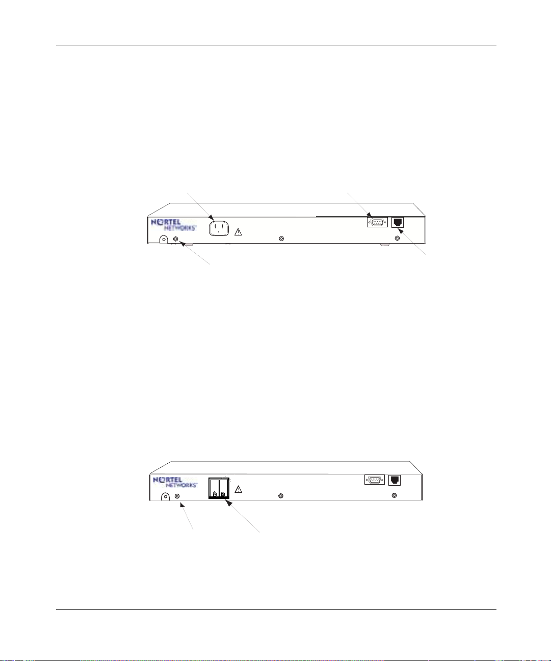
AC Power Supply for Passport 4460
The Passport 4460 AC unit has the following connectors located on the front
panel:
• 3-prong power connector (115/230 VAC)
• Management port (DB-9) (see Chapter 7, “Port Connections for the
Passport 4460”)
• Reserved service port (not used)
Power Connector
Grounding Connector
Management Port Connector
115/230V
Passport 4460 AC Unit
DC Power Supply for Passport 4460
The Passport 4460 DC unit has the following connectors located on the front
panel:
• Two-pin connector plus ground (-48 VDC) (see page 37)
• External block DC connector
• Management port (DB-9) (see Chapter 7, “Port Connections for the
Passport 4460”)
• Reserved service port (not used)
Refer to page 36 for more information on the DC unit for the Passport 4460.
115/230V
MGNT
PORT
MGNT
PORT
RESERVED
SERVICE
PORT
RESERVED
SERVICE
PORT
Not Used
Grounding Connector
Passport 4460 DC Unit
DC Connector
Reference for Passport 4460 Hardware
Page 24
24 Chapter 1 The Passport 4460 Unit
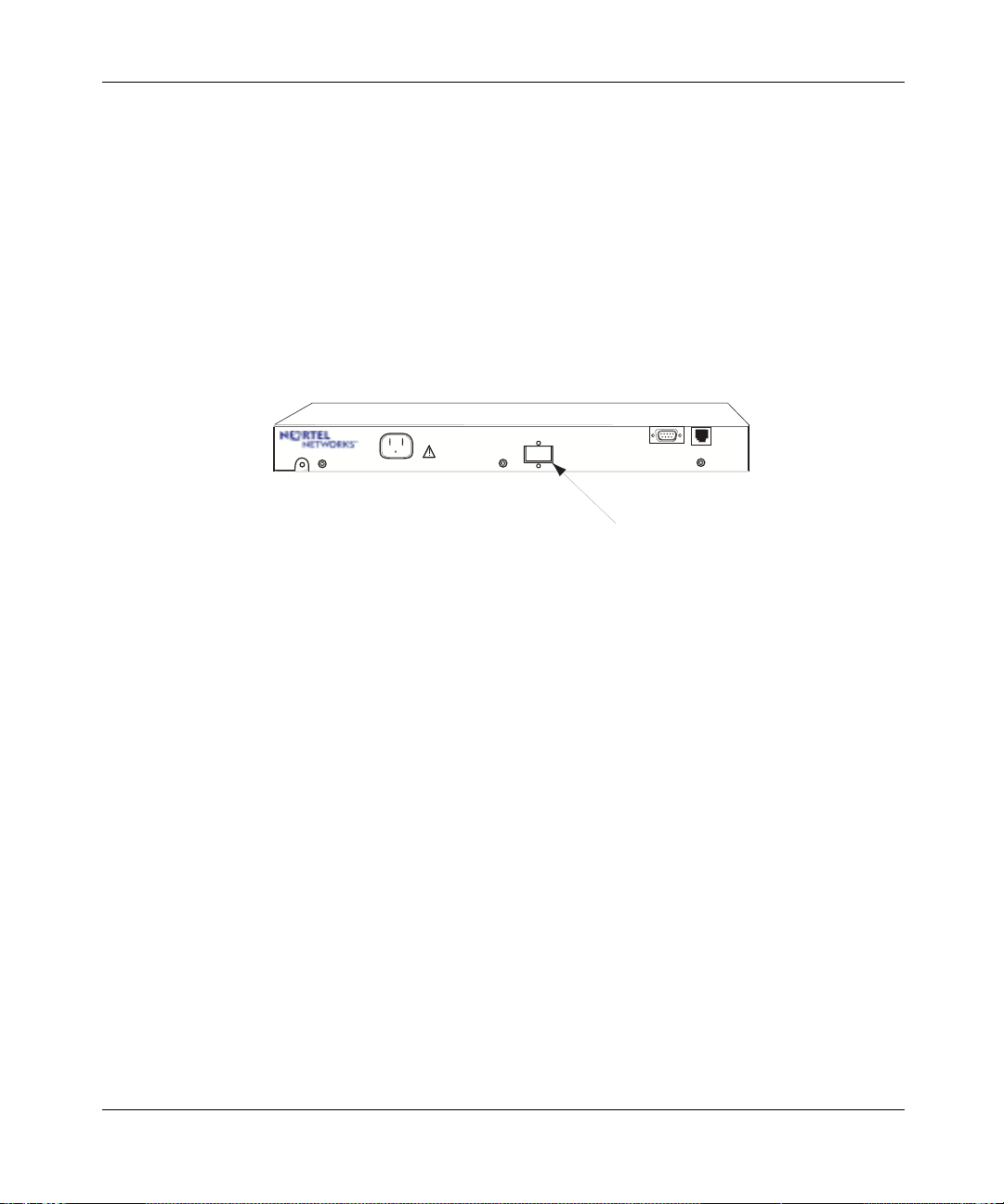
Redundant Power Supply for Passport 4460
The following connectors are located on the front of the Passport 4460 AC unit
designed for Redundant Power:
• 3-prong power connector (115/230 VAC)
• Redundant Power Supply Connector
• Management port (DB-9) (see Chapter 7, “Port Connections for the
Passport 4460”)
• Reserved service port (not used)
Refer to page 37 for more information on the Redundant Power Supply unit.
115/230V
Passport 4460 AC Unit
Designed for Redundant Power Supply Unit
MGNT
PORT
Redundant Power Supply Connector
RESERVED
SERVICE
PORT
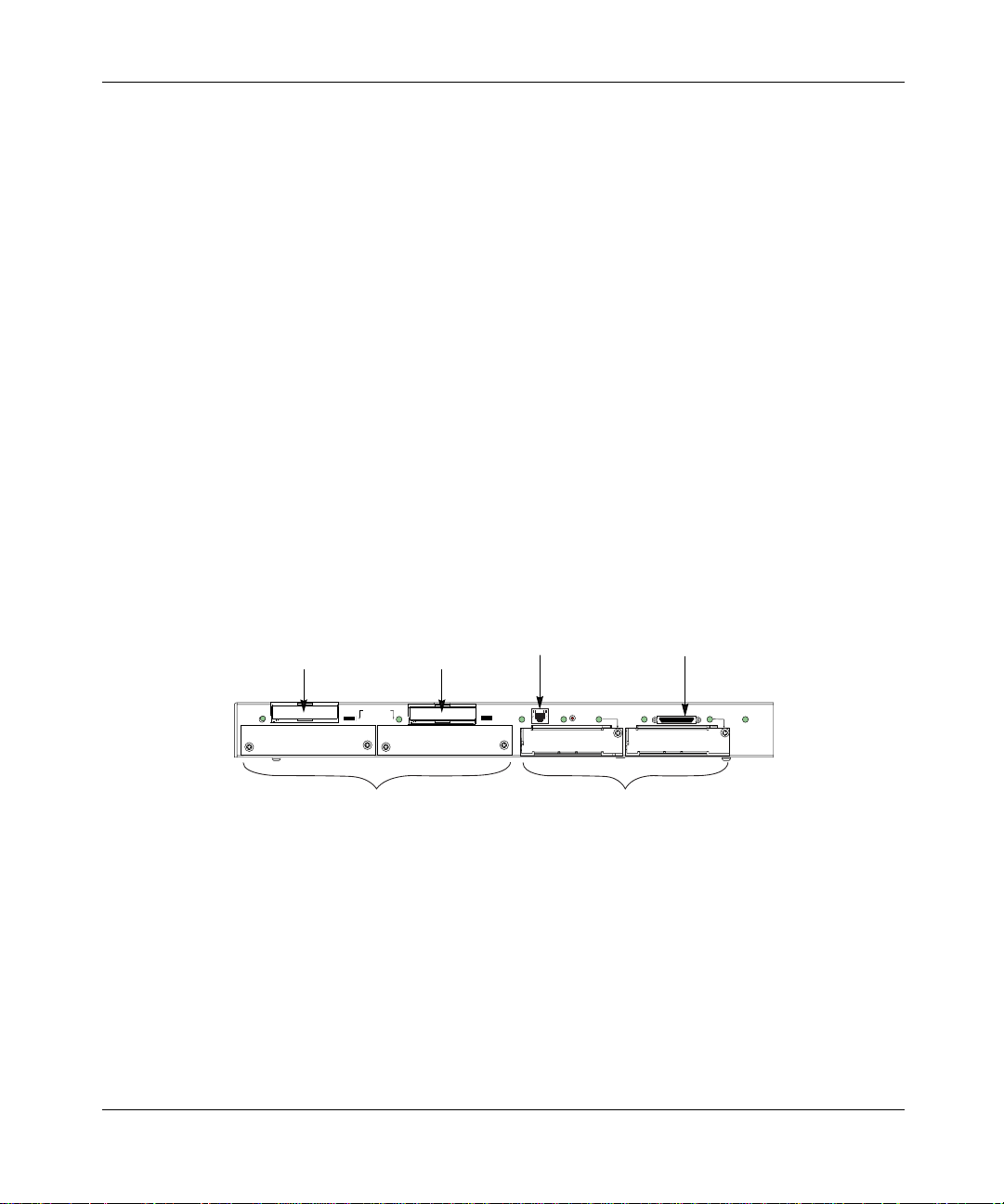
Features Located on Back Panel of Passport 4460
The back of the unit shares the same features on all units and includes the
following networking capabilities:
• Two slots for WAN adapter modules (see Chapter 2, “WAN Adapter
Modules”)
• Two expansion slots for optional data or voice modules (see Chapter 3,
“Expansion Modules”)
• One slot for a Flash module (see Chapter 4, “16 MB Flash Module”)
• One slot for a PCMCIA expansion module (see Chapter 5, “PCMCIA
Expansion Module”)
• One 10/100BASE-T LAN port (see Chapter 7, “Port Connections for the
Passport 4460”)
205677-F Rev 00
Page 25
Chapter 1 The Passport 4460 Unit 25
• One built-in serial port for either WAN or data connection
10/100BASE-T
Flash Slot
Port
PCMCIA Slot
Serial Port
EXPANSION
STAT
2
10/100
RST
P
O
R
T
2
P2 STATUS
P1 STATUS
PORT 1
P3 STATUS
SYSTEM
P
STATUS
O
R
T
3
WAN SlotsExpansion Slots
Reference for Passport 4460 Hardware
Page 26

26 Chapter 1 The Passport 4460 Unit
Checking the Package Contents
Because the Passport 4460 unit has optional configurations available, check the
packing list against the package contents to ensure you have received the proper
equipment you ordered for your installation. Report any damage to the shipping
carrier. If modules, cables, or other ordered items are missing, contact your
Certified Distributor or sales person immediately.
Save the packing materials. You may need the materials to repack the unit for
factory update.
If you ordered a... Order Code You should have received a...
Passport 4460 AC Base
Unit (with power cord)
PA4202003 • Base unit with AC power supply
• Modules ordered - installed (varies
according to network requirements)
• Management cable to D TE (DB-9 fem ale t o
DB-9 female) (part number 207490-A)
• Crossover LAN cable RJ-45 to RJ-45 (color
coded red) (part number 207232-A)
• AC power cord
• Accessory kit containi ng rack m ount ears
(2), flat-head screws (4), and rubber feet (4)
• WAN faceplates (2) used to cover unused
WAN slots
• Expansion faceplates (2) used to cover
unused expansion slots
• Software accessory kit containing PCMCIA
flash card; CD ROM consisting of software
and online documentation; and the
Passport 4460 Quick Start Guide
Reference for Passport 4460 Hardware
•
(this manual)
• Reference for Passport 4460 Cables
.
205677-F Rev 00
Page 27

Chapter 1 The Passport 4460 Unit 27
If you ordered a... Order Code You should have received a...
Passport 4460 DC Base
Unit (without power cord)
Passport 4460
Redundant Provisioned
AC Base Unit
(power cord of choice)
P A 42 020 01 • Base unit with DC power supply .
• Modules ordered - installed (varies
according to network requirements)
• Management cable to D TE (DB-9 fem ale t o
DB-9 female) (part number 207490-A)
• Crossover LAN cable RJ-45 to RJ-45 (color
coded red) (part number 207232-A)
• Accessory kit containi ng rack m ount ears
(2), flat-head screws (4), and rubber feet (4)
• WAN faceplates (2) used to cover unused
WAN slots
• Expansion faceplates (2) used to cover
unused expansion slots
• Software accessory kit containing PCMCIA
flash card; CD ROM consisting of software
and online documentation; and the
Passport 4460 Qui ck Start Guide
•
Reference for Passport 4460 Hardware
(this manual)
.
• Reference for Passport 4460 Cables
PA4202004 • Base unit provisioned to attach to RPSU
• Modules ordered - installed (varies
according to network requirements)
• Management cable to DTE (DB-9 to DB-25
female) (part number 207490-A)
• Crossover LAN cable RJ-45 to RJ-45 (color
coded red) (part number 207232-A)
• Accessory kit containi ng rack m ount ears
(2), flat-head screws (4), and rubber feet (4)
• WAN faceplates (2) used to cover unused
WAN slots
• Expansion faceplates (2) used to cover
unused Expansion slots
• Software accessory kit containing PCMCIA
flash card; CD ROM consisting of software
and online documentation; and the
Passport 4460 Qui ck Start Guide
•
Reference for Passport 4460 Hardware
(this manual)
.
• Reference for Passport 4460 Cables
Reference for Passport 4460 Hardware
Page 28

28 Chapter 1 The Passport 4460 Unit
Considerations for Installing the Unit
A Passport 4460 uni t is typi cally inst alled i n one o f two p laces : eithe r on a surf ace
(such as a table or desk) in a lab or office, or in an equipment rack (see the
“Rackmount Installation” on page 29). The other considerations for site
preparation are making sure the selected location conforms to the following
environmental criteria:
• space requirements
• surrounding temperature
• distance to the AC outlet (a 6-foot power cord is supplied)
The following table of specifications and accompanying illustration provide
information about the unit that will assist you in placing the unit in a location
appropriate for your needs:
Dimensions
Width 43.8 cm (17.25 in.)
Height 4.4 cm (1.75 in.) without rubber feet
4.6 cm (1.80 in.) with rubber feet
Depth 33 cm (13.0 in.)
Weight 5.9 kg (13 lbs.)
205677-F Rev 00
Temperature
Operating 5 to 40
Storage -40
Relative Humidity
Operating 10-90% non-condensing
Storage 0-95% non-condensing
Power Requirements
AC 100-240 VAC, -5%, +10%
DC 36-72 VDC
°C (32 to 104°F)
to 70°C (-40 to 15 8°F)
43-63 Hz, 65 Watts
@ 3A maximum
Page 29
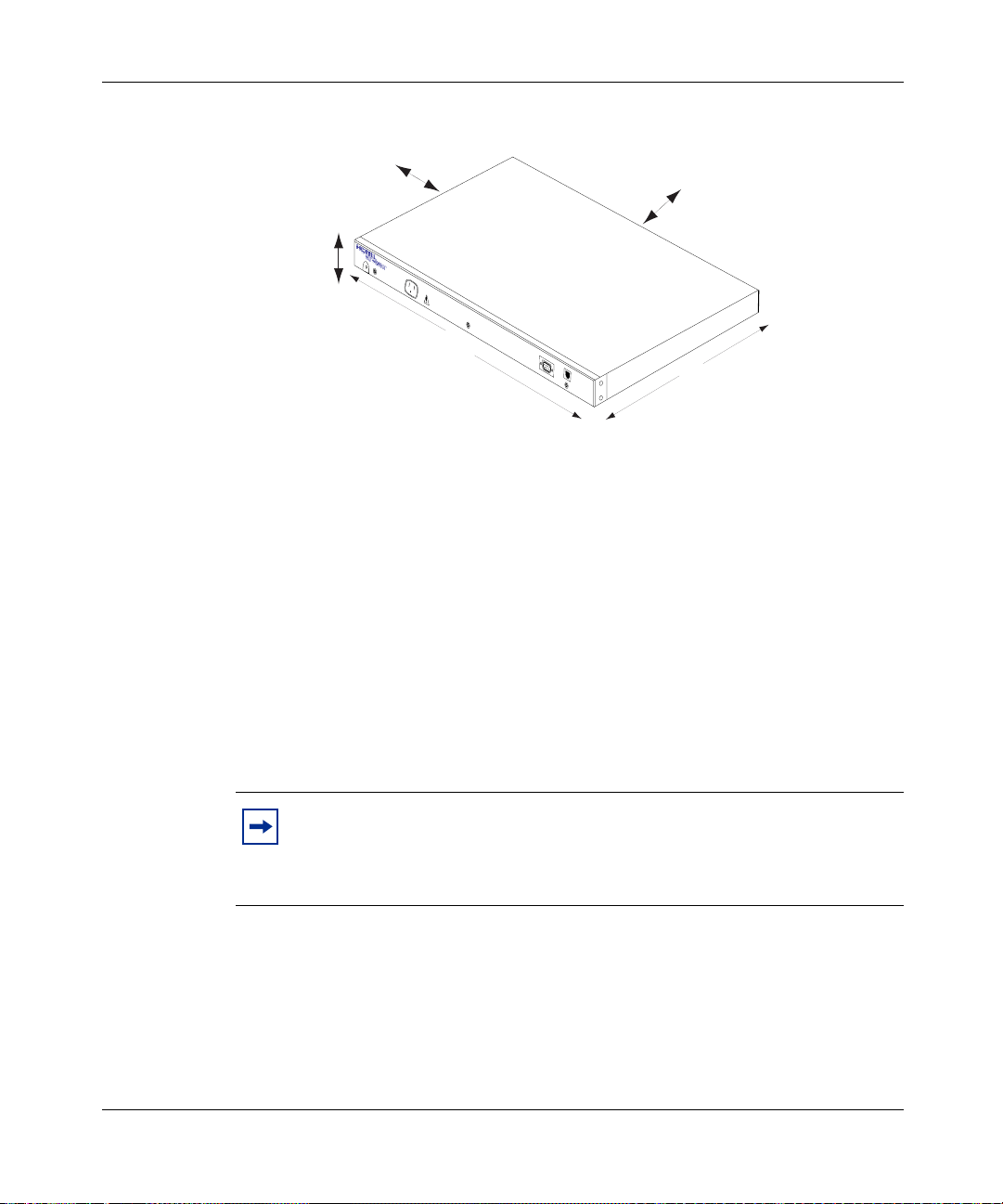
Chapter 1 The Passport 4460 Unit 29
Allow 5.08 cm (2 inches),
or greater, for air vents
4.4 cm
(1.75 inches)
115/230V
Allow 30.5 cm (12 inches),
or greater, for access
43.8 cm
(17.25 inches)
Rackmount Installation
For installing the Passport 4460 unit in a 19-inch rack, use the accessory kit
provided. Each accessory kit contains the following parts:
•Four screws
• Two mounting ears (L-shaped brackets)
The cabinet manufacturer should have provided you with the necessary hardware
for attachi ng the L-shaped bracket to th e cabinet.
Note: When installing Passport 4460 units in a rack, you may want to
place them in the rack with the rear (module side) of the unit facing
towards the front. This allo ws for easy ac ces s to the modules and enables
you to read the indicators without going to the rear of the cabinet.
MGNT
PORT
RESERVED
SERVICE
PORT
33 cm
(13.0 inches)
Reference for Passport 4460 Hardware
Page 30

30 Chapter 1 The Passport 4460 Unit
This list of safety measures must be complied with prior to mounting the
Passport 4460 unit.
Caution:
• Manufacturer’s maximum recommended ambient temperature (Tmra) for the
Passport 4460 unit rack environment is 45°C and should not be exceeded.
• Place the unit in an environment that does not restrict the amount of air flow
required for safe operation.
• Mount the rack and ens ure it is eve nly balan ced to avoid a possibl e hazardou s
condition due to uneven load ing .
• Pay special attention when connecting the unit to the power supply, and
consider the effect that overloading might have on overcurrent protection and
supply wiring. Approp riate eq uipme nt namepl ate r atings sh ould be used w hen
addressing this concern.
• Make sure each unit is properly grounded.
To install your unit into a cabinet:
1 Fasten the L-shaped brackets onto the sides of the Passport 4460 unit.
205677-F Rev 00
2 Place the unit in the cabinet making sure to line up the holes on the L-shaped
bracket with the holes in the frame of the cabinet.
Page 31

Chapter 1 The Passport 4460 Unit 31
3 Fasten the L-shaped bracket onto the frame of the cabinet.
EXPANSION
2
10/100
P
STAT
O
RST
R
P2 STATUS
T
2
P1 STATUS
PORT 1
P3 STATUS
SYSTEM
P
O
STATUS
R
T
3
Note: The L-shaped side brackets in the cabinet are adjustable. If y our
cabinet has a door, you may have to slide the brackets further into the
cabinet to allow the door to close.
Reference for Passport 4460 Hardware
Page 32

32 Chapter 1 The Passport 4460 Unit
Setting Up the Passport 4460
Once you have install ed your Passpor t 4460 unit, you must do the follo wing to set
your unit up for operation:
Installing the PCMCIA Flash Module
Insert the PCMCIA Flash module into the Flash slot on the Passport 4460. This
module is used for downloading system configuration software. For additional
information on the PCMCIA Flash module, go to Chapter 4.
EXPANSION
2
Installing Modules
205677-F Rev 00
10/100
P
STAT
O
RST
R
P2 STATUS
T
2
P1 STATUS
PORT 1
P3 STATUS
SYSTEM
P
O
STATUS
R
T
3
In most cases your unit arrived wit h the modules instal led. If this is so , proceed to
the next phase of the setup. If not, refer to Chapters 2 and 3 for additional
information.
Page 33

Chapter 1 The Passport 4460 Unit 33
Connecting the Workstation
Connect one end of t he management cable to the se rial por t of the PC workstat ion.
Connect the other end to the management port of the Passport 4460. For
additional information on management port connections, go to Chapter 7.
Management Port Connector
PC
RESERVED
SERVICE
PORT
Serial Port
115/230V
MGNT
PORT
Connecting a Power Supply
Make the power connection requi red for your setu p: AC power supply, DC power
supply, or redundant AC power supply. See the following sections.
Connecting the AC Unit
Note: Before connec ting yo ur unit to it s po wer sour ce, the 16 MB Flash
Module must be installed. Any optional modules are assumed to have
been inserted in the unit. Refer to Chapters 2, 3, and 4 for installation
instructions of WAN Adapter Modules, Expansion Modules, and the 16
MB Flash Module, respectively.
The AC-powered Passport 4460 unit requires an agency-recognized AC power
cord, rated at 1 25 Volts and 10 Amps. The AC p ower cord s upplied wi th you r u nit
is a molded three-prong power cord with an appropriate connector to match the
power outlet in your country, as shown on the following page:
Reference for Passport 4460 Hardware
Page 34

34 Chapter 1 The Passport 4460 Unit
115/230V
Typical
Connector
MGNT
PORT
RESERVED
SERVICE
PORT
Three-wire Power Cord
If a power cord is not supplied with your AC unit or not available with the Sales
order, make sure that any power cord used with the Passport 4460 unit meets the
ratings of 125 Volts and 3 Amps or 254 Volts and 1.5 Amps.
Warning: Before turning on the unit, if you are using a two-prong
power cord, make sure there is a separate ground wire connection
between the unit chassis and input power source ground to provide
proper grounding.
115/230V
MGNT
PORT
RESERVED
SERVICE
PORT
205677-F Rev 00
Safety
Ground
Green with Yellow Strip
Ground Wire
Two-wire
Power Cord
<0.5 ohm
Two-Prong Power Connector
To a Fixed Earth Ground Point
Page 35

G
Chapter 1 The Passport 4460 Unit 35
Warning: Countries other than U.S.A. You should have received a
power cord with a two-prong power connector and a green-with-yellow
stripe ground wire as s hown in the exa mples be low. If the power outlet is
not grounded, contact an electrician to connect the green-with-yellow
stripe wire to a fixed earth grounding point.
Safety
Ground
Green with Yellow Strip
Ground Wire
Green with Yellow Strip
Ground Wire
<0.5 ohm
115/230V
<0.5 ohm
115/230V
Two-wire
Power Cord
Two-Prong Power Connector
To a Fixed Earth
To a Fixed Earth Ground Point
round Point
Three-wire
Power Cord
Two-Prong Power Connector
MGNT
PORT
RESERVED
SERVICE
PORT
RESERVED
SERVICE
PORT
MGNT
PORT
Note: To turn on the unit, plug the power cord into the front of the
chassis and into an appropriately grounded three-pin wall outlet.
You can proceed to Chapter 6, “Cables,” to continue your unit setup.
Reference for Passport 4460 Hardware
Page 36

36 Chapter 1 The Passport 4460 Unit
Connecting the DC Unit
Before connecting your unit to its power source, t he 16 MB Flash Module must b e
installed. Any optional modules are assumed to have been inserted in the unit.
Refer to Cha pters 2, 3, and 4 for installation instructions of WAN Adapter
Modules, Expansion Modules, and the 16 MB Flash Module, respectively.
Warning: Before turning on the Passport 4460 unit, be sure that the unit
is properly grounded. The ground is attached to the screw at the side of
the main power connector on the unit.
The DC version of the Passport 4460 unit has an external terminal block that is
connected to the main power connected at the front of the unit.
Caution: When using a DC power supply, be sure that a readilyaccessible disconnect device is incorporated in the DC source wiring.
205677-F Rev 00
A small black plastic door covers the terminal points. To access the terminal
points, use your finger to gently pull off the plastic door from the top.
RESERVED
SERVICE
PORT
Grounding Connector
115/230V
Passport 4460 DC Unit
DC Connector
MGNT
PORT
Page 37

Chapter 1 The Passport 4460 Unit 37
The DC power source must be connected to the unit by attaching the +48 VDC,
-48 VDC, and the chassis ground cords to their respective terminal points located
on the block as shown below.
Warning: The connector attaching the Passport 4460 unit to the DC
power source must have a single disconnect device.
+4
115/230V
etur
+4
etur
Safety Ground
+48V -48V
You can proceed to Chapter 6, “Cables, to continue your unit setup.
Connecting a Passport 4460 Unit with Redundant Power
The Passport 4460 Redundant AC Base unit is designed to attach to the RPSU
(Redundant Power Supply Unit) for a power redundant solution. It is the same
chassis as the Passport 4460 AC unit except that it has a connector at the
center-front of the chassis that allows for the attachment to the RPSU.
Before connecting your unit to its power source, t he 16 MB Flash Module mus t be
installed. Any optional modules are assumed to have been inserted in the unit.
Refer to Cha pters 2, 3, and 4 for installation instructions of WAN Adapter
Modules, Expansion Modules, and the 16 MB Flash Module, respectively.
Reference for Passport 4460 Hardware
Page 38

38 Chapter 1 The Passport 4460 Unit
These illustrations show a Passport 4460 unit with redundant power supply
connector and the redundant power supply.
115/230V
Passport 4460 AC Unit
Designed for Redundant Power Supply Unit
1
0
I
0
MGNT
PORT
RESERVED
SERVICE
PORT
Redundant Power Supply Connector
1
0
RESERVED
MGNT
PORT
115/230V
115/230V
DC Power Cable
(secondary voltages)
SERVICE
PORT
MGNT
PORT
RESERVED
SERVICE
PORT
I
0
205677-F Rev 00
Note: When using the Passport 4460 unit and redundant power supply
unit (RPSU), make sure the Passport 4460 unit is either stacked on top of
the RPSU or beside the RPSU. Do not stack the RPSU on top of the
Passport 4460 unit.
For more information on the RPSU, refer to the Quick Installation and Reference
for the Model RPSU Redundant Power Supply Unit document (part number
893-823-A) that is provided with the unit.
You can proceed to Chapter 6, “Cables,” to continue your unit setup.
Page 39

Replacing Hardware Modules
If you need to replac e a hard ware mo dule wit h a dif f erent type of modul e (such as
replacing a two-port serial data expansion module with a six-port serial data
expansion module), and you have configured ports on the module that you are
replacing, you must reset the unit to factory defaults after installing the new
module. If you don’t reset the unit to factory defaults, the configuration may be
corrupted due to different ifindixes used by the new module.
Following is the recommended procedure to accomplish this.
1 Before powering-down the unit, use the Mass Deployment and Reporting
Tool to generate a configuration script file from that unit.
Refer to the Using the Passport 4400 Mass Deployment and Reporting Tool
manual for detailed instructions.
2 Modify the ge nerated CLI script file to eliminate the entries for the module
that you are removing.
Chapter 1 The Passport 4460 Unit 39
3 Power-down the unit.
(As noted in “Installing/Removing WAN Adapter Modules” on page 42 and
“Installing/Removing the Expansion Module” on page 56, you must
power-down the unit before removing or inserting a module.)
4 Swap the two modules.
5 Power-up the unit.
6 Perform a default reset to set the configuration to factory defaults.
7 Use the Mass Deployment and Reporting Tool Downloader to reload the
modified configuration file to the defaulted Passport 4460.
8 Configure the ports on the new module, as desired.
Use of the Mass Deployment and Reporting Tool is optional. The alternative is to
manually re-configure the unit after performing the default reset.
Reference for Passport 4460 Hardware
Page 40

40 Chapter 1 The Passport 4460 Unit
205677-F Rev 00
Page 41

Chapter 2
WAN Adapter Modules
This chapter describes the WAN adapter modules available for the Passport 4460
unit. The adapter modules are designed to offer a series of WAN protocols
connecting one or more remote locations over common carrier-provided lines.
The Passport 4460 is capable of supporting any two WAN adapter modules.
The following topics are discussed in this chapter.
Topic Go to....
Installing/Removing WAN Adapter Modules page 42
T1/FT1 DSU/CSU Adapter Module page 44
E1/FE1 G.703/G.704 Adapter Modules (RJ and BNC) page 45
ISDN BRI Adapter Modules (S/T and U Interface) page 48
56/64K DSU/CSU Module page 52
Serial Module page 53
41
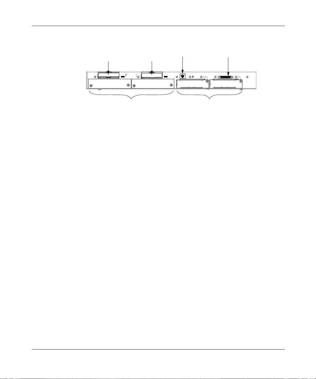
The base module of the Passport 4460 unit has two modular WAN slots, capable
of housing any two optio nal WAN adapter mod ule s. Thes e slot s are loca ted on the
rear (module side) of the chassis, at the lower right side of the unit.
EXPANSION
2
STAT
10/100
RST
P
O
R
T
2
P2 STATUS
P1 STATUS
WAN Slots with Faceplates On
Reference for Passport 4460 Hardware
PORT 1
P3 STATUS
SYSTEM
P
STATUS
O
R
T
3
Page 42

42 Chapter 2 WAN Adapter Modules
Installing/Removing WAN Adapter Modules
It is assumed that your unit arrived with the modules already installed. There are
times it may be necessary to remove or install new modules. Use the procedure
below to accomplish this task.
Do not plug in the power cord until all modules and connectors have been
properly installed.
Warning: Do not remove or insert modules while the Passport 4460 is
operating. To do so could result in damage to the Passport 4460 unit.
To ensure a proper fit of the WAN module, insert the module so that the back
panel is facing up and is readable.
Caution: When installing or r emoving expansion modul es, be sure that
the module is inserted properly and does not slip out of its guide. This
could cause damage to either the base module or the adapter module.
205677-F Rev 00
Caution: Use an anti-static wrist strap when handling any module.
Failure to do so could result in damage to the module.
To install a WAN adapter module:
1 Use a Phillips screwdriver to remove the screw on the blank faceplate
covering the slot(s) you will be using. Save the screw(s), you will need them
later. Pull off the blank faceplate covering the slot. Save the faceplate, you
may need it later.
2 Carefully sl ide the adapter module into Port 2 or Port 3, located at the lower
right side of the Passport 4460 back panel. Make sure that the module is
pushed all the way in, so it firmly mates with the connector at the rear of the
slot.
Page 43

Chapter 2 WAN Adapter Modules 43
3 Secure the module at the upper right side using the screw that was used to
hold the blank faceplate.
EXPANSION
2
10/100
P
STAT
O
RST
R
P2 STATUS
T
2
P1 STATUS
PORT 1
P3 STATUS
SYSTEM
P
O
STATUS
R
T
3
To remove a WAN Module:
1 Remove the screw from the upper right side of the module.
2 Firmly grasp the front of the module and pull out.
Caution: To comply with Agency requirements, cover any unused slot
with the blank faceplate.
For additional information, see the following:
• Chapter 6, “ Cables”
• Chapter 7, “Port Connections for the Passport 4460”
• Appendix B, “Regulatory Compliance and Telephone Company
Requirements”
After the modules are in place and the system is operating, refer to the software
documentation for configuration information (see “Product documentation” on
page 17).
Reference for Passport 4460 Hardware
Page 44

44 Chapter 2 WAN Adapter Modules
T1/FT1 DSU/CSU Adapter Module
The T1/FT1 DSU/CSU Adapter Module provides a direct T1 or fractional T1
connection to a Passport unit or any other compatible device.
The T1/FT1 DSU/CSU Adapter Module is compliant with the ANSI T1.231
standards
Note: This module is designed to accept an RJ-48 connec tor; howe v er , it
is compatible with an RJ-45 cable connector.
Both Port 2 and Port 3 can support the T1/FT1 DSU/CSU Adapter Module.
Pin 1
Red Alm
Yel Alm
DSU/CSU
RJ-48 Pin Assignments
1
2
3
4
5
6
7
8
Pins 3, 6, 7, 8 Not Connected
T1/FT1
Receive Data from Network (Ring)
Receive Data from Network (Tip)
Transmit Data to Network (Ring)
Transmit Data to Network (Tip)
The T1/FT1 DSU/CSU Adapter Module has four indicators.
Note: During diagnostic t esting, the ind icators bl ink on and of f. Ho we ver ,
they do not indicate data transfer until you have configured and enabled
software services.
Indicators
Loop
Sync
205677-F Rev 00
Page 45

Chapter 2 WAN Adapter Modules 45
The chart below defines the functions of the indicator lights for the T1/FT1 DSU/
CSU Adapter Module.
Indicator Color Definition
Red Alarm Red Lights when the T1 port is in a red alarm state
Yellow Alarm Amber Lights when the DS U/CSU has receiv ed a yello w alarm
Loop Amber Lights when the T1 interface is placed in loopback
Sync Green Lights when the T1 port is synchronized with the T1
from the T1 network
mode
network
For additional information, see the following:
• Chapter 6, “ Cables”
• Appendix A, “Indicators”
• Appendix B, “Regulatory Compliance and Telephone Company
Requirements”
After the modules are in place and the system is operating, refer to the software
documentation for configuration information (see “Product documentation” on
page 17).
E1/FE1 G.703/G.704 Adapter Modules (RJ and BNC)
Two E1/FE1 G.703/G.704 Adapter Modules are available, depending on the
connector type you are using:
• E1/FE1 G.703/G.704 (RJ) Adapt er Module with DSU functionali ty at 120
ohms, with an RJ-48 physical connector
• E1/FE1 G.703/G.704 (BNC) Adapter Module with DSU functionality at
75 ohms, with an external balun to provide BNC connectivity
Reference for Passport 4460 Hardware
Page 46

46 Chapter 2 WAN Adapter Modules
The integrated DSU/CSU functionality allows direct connection to the E1
network, rather than connecting via an external adapter. This solution simplifies
connection to an E1 ATM carrier.
Both Port 2 and Port 3 can support the E1/FE1 G.703/G.704 (BNC) adapter
module.
Note: Determinin g the prope r module to use (75 ohms or 120 ohms ) will
depend on the network requirements of the location where the Passport
4460 resides.
The E1/FE1 G.703/G.704 (BNC) adapter module must be inserted into the unit
with the component side up.
Note: This module is designed to accept an RJ-48 connec tor; howe v er , it
is compatible with an RJ-45 cable connector.
An 8-pin RJ-48 jack is provided to interface with the E1 network.
205677-F Rev 00
Pin 1
RJ-48 Pin Assignments
1
2
3
4
5
6
7
8
Pins 3, 6, Ground
Pins 7, 8, Not Connected
Local
Loop
E1/FE1
G.703
Receive Data from Network
Receive Data from Network
Transmit Data to Network
Transmit Data to Network
Alarm
Remote
Alarm
Sync
Indicators
Page 47

Chapter 2 WAN Adapter Modules 47
The following illustration shows how to connect the G.703 balun to the Passport
4460 unit. Connect the cable from the E1/FE1 G.703/G.704 (BNC) adapter
module to the RJ-48 connec tor o n the G.703 Balun ad apter. Attach the BNC cable
to the BNC connector on the associated E1 DSU device.
EXPANSION
2
1
3
2
4
To BNC Connector
10/100
STAT
RST
E1/FE1
G.703
DDS
56K/64K
DSU/CSU
P2 STATUS
Local
TxRxCD
Loop
Alarm
Remote
Sync
Test
Alarm
P
O
R
T
2
PORT 1
P1 STATUS
U
ISDN BRI
with NT1
Complies with FCC Rules Part 68 Reg. Number 4P8USA-24512-DE-N
SYSTEM
P3 STATUS
P
STATUS
O
D
B1
R
B2
DD
T
3
RJ-48 Side of G.703 Balun
The E1/FE1 G.703/G.704 Adapter Module (RJ or BNC) has four indicator lights.
Note: During diagnostic t esting, the ind icators bl ink on and of f. Ho we ver ,
they do not indicate data transfer until you have configured and enabled
software services.
The chart belo w defines the funct ions of the i ndica tor l ights for t he E 1/FE1 G.703 /
G.704 Adapter Module (RJ or BNC).
.
Indicator Color Definition
Local Alarm Amber Lights when the E1 port is in a local alarm state
Remote Alarm Amber Lights when the E1 port has received a remote alarm
from the E1 network
Loop Amber Lights when the E1 interface is placed in loopback
Sync Green Lights when the E1 port is synchronized with the E1
mode
network
Reference for Passport 4460 Hardware
Page 48

48 Chapter 2 WAN Adapter Modules
For additional information, see the following:
• Chapter 6, “ Cables”
• Appendix A, “Indicators”
• Appendix B, “Regulatory Compliance and Telephone Company
Requirements”
After the modules are in place and the system is operating, refer to the software
documentation for configuration information (see “Product documentation” on
page 17).
ISDN BRI Adapter Modules (S/T and U Interface)
The ISDN (Integrated Ser vices Digita l Network) BRI (Basic Rate Interfac e) WAN
modules are used as primary network li nk connect ions to the WAN, or for backup
in case of a l ine failure. Both Port 2 and Port 3 can support the ISDN BRI WAN
modules.
205677-F Rev 00
There are two ISDN BRI WAN adapter modules:
• ISDN BRI (S/T Interface) Adapter Module
• ISDN BRI (U Interface) Adapter Module
The ISDN BRI provides B-channels and D-channels:
• The D-channel carries control and signaling informat ion between t he user
and the network at 16 kb/s.
• The two B-Channels carry data, voice, and other services at 64 kb/s.
Page 49

ISDN BRI (S/T Interface) Adapter Module
Caution: The single-port BRI Expansion Module (S/T) cannot be
directly connected to the network.
The Single-Port BRI Expansion Module (S/T) ca nnot be directly connec te d t o the
network and requires connection to an NT1 (Network Terminating unit, type 1),
an external device provided by the phone company. The NT1 accepts a 2-wire
signal and converts it to a 4-wire signal that sends and receives to and from
devices within the home or a business.
Note: This module is designed to accept an RJ-48 connec tor; howe v er , it
is compatible with an RJ-45 cable connector.
Pin 1
RJ-48 Pin Assignments
1
2
3
4
5
6
7
8
Chapter 2 WAN Adapter Modules 49
Indicator
S/T
ISDN BRI
Complies with Part 68, FCC Rules
FCC Reg. Number SCNUSA-32845-XD-N
Transmit Data to Network (TX+)
Receive Data from Network (Rx+)
Receive Data from Network (RX-)
Transmit Data to Network (TX-)
Pins 1, 2, 7, 8 Not Connected
The ISDN BRI S/T WAN Module has a single indicator light. The indicator stays
on when the unit is using the D-channel (control and signal information).
Note: During diagnostic testing, the indicator blinks on and off.
However, it does not indicate data transfer until you have configured and
enabled software services.
Reference for Passport 4460 Hardware
Page 50

50 Chapter 2 WAN Adapter Modules
For additional information, see the following:
• Chapter 6, “ Cables”
• Appendix A, “Indicators”
• Appendix B, “Regulatory Compliance and Telephone Company
Requirements”
After the modules are in place and the system is operating, refer to the software
documentation for configuration information (see “Product documentation” on
page 17).
ISDN BRI (U Interface) Adapter Module
ISDN BRI (U Interface) is a 2-wire BRI interface obtained from an ISDN
provider or local exchange. It cannot be directly connected to the network and
requires connection to an NT1 (Network Terminating unit, type 1), an external
device provided by the phone company. The NT1 accepts a 2-wire signal and
converts it to a 4-wire signal that sends and receives to and from devices within
the home or a business
205677-F Rev 00
Note: This module is designed to accept an RJ-48 connec tor; howe v er , it
is compatible with an RJ-45 cable connector.
Pin 1
Complies with FCC Rules Part 68 Reg. Number 4P8USA-24512-DE-N
RJ-48 Pin Assignments
1
2
3
4
5
6
7
8
Pins 1, 2, 3, 6, 7, 8 Not Connected
U
ISDN BRI
with NT1
Tip of Pair to Network
Ring of Pair to Network
D
DD
Bi-direction - Depending on
Mode of operation
Indicators
B1
B2
Page 51

Chapter 2 WAN Adapter Modules 51
The ISDN BRI (U Interface) Adapter Module has four indicator lights.
Note: During diagnostic testing, the indicators blink on and off.
Howev er, they do not indicate data transfer unt il you ha v e co nf igur ed and
enabled software services.
The chart below describes the indicator functions.
Indicator Definition
D (D-channel; 16 KB
Management Channel)
DD (Data Detect) Lights when the ISDN BRI interface detects connection to
B1 (B-channel #1; 64 KB
Data Channel)
B2 (B-channel #2; 64 KB
Data Channel)
Lights when the unit is using the D-channel
an external swit ch device
Lights when the unit is using B-channel #1
Lights when the unit is using B-channel #2
For additional information, see the following:
• Chapter 6, “ Cables”
• Appendix A, “Indicators”
• Appendix B, “Regulatory Compliance and Telephone Company
Requirements
After the modules are in place and the system is operating, refer to the software
documentation for configuration information (see “Product documentation” on
page 17).
Reference for Passport 4460 Hardware
Page 52

52 Chapter 2 WAN Adapter Modules
56/64K DSU/CSU Module
The 56/64K DSU/CSU module supports the Digital Data Service (DDS) without
the secondary signaling channel. Both Port 2 and Port 3 can support the 56/64K
DSU/CSU module.
Note: This module is designed to accept an RJ-48 connec tor; howe v er , it
is compatible with an RJ-45 cable connector.
The adapter module must be inserted into the unit with the component side up.
Pin 1
RJ-48 Pin Assignments
1
2
3
4
5
6
7
8
DDS
56K/64K
DSU/CSU
Pins 3, 4, 5, 6 Not Connected
Tx
Rx
Transmit Data to Network
Transmit Data to Network
Receive Data from Network
Receive Data from Network
Indicators
CD
Test
The 56/64K DSU/CSU WAN Module has four indicators.
The chart below des cribes the indic ator funct ions for the 56/ 64K DSU/CSU WAN
Module.
Indicator Status Definition
TxD (Transmit Data) Lights when the interface transmits data over the network
RxD (Receive Data) Lights when the interface receives data from the network
CD (Carrier Detect) Lights when the interface detects a connection to another device
Test Lights when the interface is in test or loopback mode
205677-F Rev 00
Page 53

For additional information, see the following:
• Chapter 6, “ Cables”
• Appendix A, “Indicators”
• Appendix B, “Regulatory Compliance and Telephone Company
After the modules are in place and the system is operating, refer to the software
documentation for configuration information (see “Product documentation” on
page 17).
Serial Module
The Serial Module provides additional port capability, identical to Port 1 on the
base module. The module’s 50-pin connector supports RS-232/V.24, V.35, V.36,
and X.21 interfaces, depending on the cable used. The module can support both
DTE and DCE modes. Both Port 2 and Port 3 can support the Serial Module.
Chapter 2 WAN Adapter Modules 53
Requirements”
The Serial Module must be inserted into the unit with the component side up.
Indicator
SERIAL WAN
Note: Pin assignments and configuration information are the same as for
the Serial Port located on the Passport 4460 Base Module. This
information is located in Chapter 7 of th is manual.
Reference for Passport 4460 Hardware
Page 54

54 Chapter 2 WAN Adapter Modules
The Serial Module indicator light is tri-colored and lights up (green = OK;
red = failure; amber = no sig nal) when the serial interface is operati ng.
Status Definition
Green Everything is functioning; indicates any of the following:
Red Failure
Amber Configured - no signal
For additional information, see the following:
• Chapter 6, “ Cables”
• Chapter 7, “Port Connections for the Passport 4460”
• Appendix B, “Regulatory Compliance and Telephone Company
Requirements”
• Interface is trans mitti ng data over the network
• Interface is receiving data over the network
• Interface detects a connection to another device
• Interface is in test or loopback mode
205677-F Rev 00
After the modules are in place and the system is operating, refer to the software
documentation for configuration information (see “Product documentation” on
page 17).
Page 55

Chapter 3
Expansion Modules
This chapter contains th e following voice and data expansion module in format ion :
Topic Page
Installing/Removing the Expansion Module page 56
T1 Voice Expansion Module page 58
E1 Voice Expansion Module page 59
Digital Voice Expansion Module page 61
FXS Voice Expansion Module (Dual and Quad Channel) page 62
ISDN BRI Voice Expansion Modules - S/T Interface (Single and Dual Port) page 66
2-Port Serial Data Expansion Module page 69
6-Port Serial Data Expansion Module page 71
E&M Voice Expansion Modules (Dual and Quad Channel) page 77
55
Expansion modules provide customizing and expansion of services for the
Passport 4460. The unit can accommodate two expansion modules. Any
expansion module combination is supported. These modules fit into the slots
located at the rear of the chassis, at the lower left side of the unit.
EXPANSION
2
Expansion Slots with Faceplates
STAT
10/100
RST
DDS
56K/64K
DSU/CSU
P2 STATUS
TxRxCD
Test
P
O
R
T
2
P1 STATUS
U
ISDN BRI
with NT1
Complies with FCC Rules Part 68 Reg. Number 4P8USA-24512-DE-N
PORT 1
SYSTEM
P3 STATUS
P
STATUS
O
D
B1
R
B2
DD
T
3
Reference for Passport 4460 Hardware
Page 56

56 Chapter 3 Expansion Modules
Installing/Removing the Expansion Module
It is assumed that your unit arrived with the modules already installed. There are
times it may be necess ary to re move or install n e w module s. Use t his pr ocedur e to
accomplish this task.
Do not plug in the power cord until all modules and connectors have been
properly installed.
Warning: Do not remove or insert modules while the Passport 4460 is
operating. To do so could result in damage to the Passport 4460 unit or
network interruption.
To ensure a proper fit of the e xpa nsion module, t he e x pansion slot has a groo v e o n
each side into which the module can easily slide. Turn the module so that the
component side is facing down, then slide the module into the grooves.
.
205677-F Rev 00
Caution: When installing or r emoving expansion modul es, be sure that
the module is inserted properly and does not slip out of its guide. This
could cause damage to ei ther t he Eth ernet Base Modu le or th e e xpansi on
module.
Caution: Use an anti-static wrist strap when handling any module.
Failure to do so could result in damage to the module.
To install an expansion module:
1 Use a flat-head screwdriver to remove the two screws on the blank faceplate
covering the slot(s) you will be using (see illustration above). Save the screws
and the faceplate for later use. Remove the blank faceplate and set it aside.
2 Gently slide the expansion module into the slot labeled expansion 1 or 2 (see
illustration below). Push the module all the way in so that it firmly mates with
the connector at the rear of the slot.
Page 57

Chapter 3 Expansion Modules 57
Secure the module by tightening the two spring loaded screws.
EXPANSION
2
10/100
P
STAT
O
RST
R
P2 STATUS
T
2
P1 STATUS
PORT 1
P3 STATUS
SYSTEM
P
O
STATUS
R
T
3
To remove an expansion module:
1 Loosen the two screws on the back panel of the module.
2 Grasp both screws with both hands and pull firmly to release the module.
3 Slide the module out.
Caution: To comply with Agency requirements, cover any unused slot
with the blank faceplate.
For additional information, see the following:
• Chapter 6, “ Cables”
• Chapter 7, “Port Connections for the Passport 4460”
• Appendix B, “Regulatory Compliance and Telephone Company
Requirements”
After the modules are in place and the system is operating, refer to the software
documentation for configuration information (see “Product documentation” on
page 17).
Reference for Passport 4460 Hardware
Page 58

58 Chapter 3 Expansion Modules
T1 Voice Expansion Module
The T1 Voice Expansion Module provides the following:
• Six voice channels provided on the basic module
• Expandable to 24 T1 voice channels (in si x-channel i ncrements) with
optional Digital Voice Expansion Modules (maximum of three)
• Maximum of two T1 Voice Expansion Modules per Passport 4460 unit,
providing support for up to 48 voice channels
The T1 Voice Expansion Module is compliant with the ANSI T1.231 standards
Pin 1
T1
RJ-48 Pin Assignments
1
2
3
4
5
6
7
8
Pins 3, 6, 7, 8 Not Connected
Receive Data from Network (Ring)
Receive Data from Network (Tip)
Transmit Data to Network (Ring)
Transmit Data to Network (Tip)
Indicator
A tri-color indicator light, located to the left of the RJ-48 connector on the back
panel, displays the status of the module and T1 line (see page 60 for indicator
functions).
For additional information, see the following:
• Chapter 6, “ Cables”
• Chapter 7, “Port Connections for the Passport 4460”
• Appendix B, “Regulatory Compliance and Telephone Company
Requirements”
205677-F Rev 00
Page 59

After the modules are in place and the system is operating, refer to the software
documentation for configuration information (see “Product documentation” on
page 17).
E1 Voice Expansion Module
The E1 Voice Expansion Module provides the following:
• Six voice channels provided on the basic module
• Expandable to 30 E1 voice channels (in six channel increments) with
optional Digital Voice Expansion Modules (maximum of four)
• Maximum of two E1 Voice Expansion Modules per Passport 4460 unit
providing support for up to 60 voice channels
Chapter 3 Expansion Modules 59
Pin 1
E1
RJ-48 Pin Assignments
1
2
3
4
5
6
7
8
Pins 3, 6, 7, 8 Not Connected
Receive Data from Network (Ring)
Receive Data from Network (Tip)
Transmit Data to Network (Ring)
Transmit Data to Network (Tip)
Indicator
A tri-color indicator light, located to the left of the RJ-48 connector on the back
panel, displays the status of the module and E1 line (see page 60 for indicator
functions).
For additional information, see the following:
• Chapter 6, “ Cables”
• Chapter 7, “Port Connections for the Passport 4460”
Reference for Passport 4460 Hardware
Page 60

60 Chapter 3 Expansion Modules
• Appendix B, “Regulatory Compliance and Telephone Company
Requirements”
• Appendix C, “Specifications”
After the modules are in place and the system is operating, refer to the software
documentation for configuration information (see “Product documentation” on
page 17).
The indicator func tions for the T1 and E1 Voice Exp ansion Mod ules ar e iden tical .
Refer to the chart below for definitions.
Indicator Status Definition
Off No connection
Red - slow flash Line in loopback or diagnostic mode
Red - fast flash In Red Alarm state - unit does not see transmission from the
Red - solid Module failed self test diagnostics
other side (sync loss greater than 2.5 seconds)
205677-F Rev 00
Yellow - slow flash (not defined)
Yel low - fa st fla sh Remote in Red Alarm and local unit in Yellow Alarm state;
receiving indication from remote side that local unit is seeing
remote, but remote unit cannot see local unit
Yellow - solid (not defined)
Green - slow flash (not defined)
Green - fast flash T1/E1 link up - sensing clock slips
Green - solid T1/E1 link up - sync acquired
Page 61

Digital Voice Expansion Module
The Digital Voice Expansion Module is an expansion daughter card that fits
directly onto the T1 or E1 Voice Expansion Module. This module provides the
following:
• Adds six additional voice channels with compression
• Up to three additional Digital Voice Expansion Modules per T1 module
(six channel increments up to 24 channels)
• Up to four additional Digital Voice Expansion Modules per E1 module
(six channel increments up to 30 channels)
The Digital Voice Expansion Module connector positions are labeled as follows:
• X2 (DSP2) through X4 (DSP4) on theT1 Voice Expansion Module
• X2 (DSP2) through X5 (DSP5) on the E1 Voice Expansion Module
Follow the number sequence when mounting Digital Voice Expansion Modules.
The illustration below shows a Digital Voice Expansion Module being mounted
on a T1 Voice Expansion Module in the X4 (DSP4) posit io n aft er X2 (DSP2) and
X3 (DSP3) have already been mounted. X5 (DSP5) is available only on the E1
Voice Expansion Module.
Chapter 3 Expansion Modules 61
Digital Voice Expansion
Module
X4 (DSP4)
X5 (DSP5)
X3 (DSP3)
X2 (DSP2)
(DSP1)
T1Voice Module
Reference for Passport 4460 Hardware
Page 62

62 Chapter 3 Expansion Modules
Caution: The Digital Voice Expansion Module is very sensitive to
damage from improper handling. Repetitive removing and installation
may cause damage to the module. Use an anti-static wrist strap when
handling any module. Failure to do so could result in damage to the
module. All removal and installation must be done by a qualified
technician.
For additional information, see the following:
• Chapter 6, “ Cables”
• Chapter 7, “Port Connections for the Passport 4460”
After the modules are in place and the system is operating, refer to the software
documentation for configuration information (see “Product documentation” on
page 17).
FXS Voice Expansion Module (Dual and Quad Channel)
205677-F Rev 00
The FXS Voice Expansion Module (Dual and Quad Channel) supports the
following:
• Short loop applications (up to 3,000 feet)
• Loop Start
• Ground Start (enables direct connectivity to PBX CO trunk lines)
• 25 Hz and 50 Hz ringing frequency
• Dial Pulse and DTMF detection
The Passport 4460 can support two FXS modules.
Page 63

Chapter 3 Expansion Modules 63
The illustration below shows a dual channel FXS Voice Expansion Module back
panel.
Indicators
FXS
RJ-11 Pin Assignments
1
2
3
4
5
6
Pins 1, 2, 5, 6 Not Connected
1 2
Tip
Ring
Two Center Pins
}
Pin 1
The illustration below shows a quad channel FXS Voice Expansion Module back
panel.
Indicators
Pin 1
FXS
1 2 3 4
RJ-11 Pin Assignments
1
2
3
4
5
6
Pins 1, 2, 5, 6 Not Connected
Tip
Ring
Two Center Pins
}
Reference for Passport 4460 Hardware
Page 64

64 Chapter 3 Expansion Modules
The FXS Voice Expansion Module has a default ring voltage set to 40 VRMS per
channel. To allow for a 50 VRMS per channel you must c hange the pi n settings on
jumpers J2, J3, J15, J16 (see chart and illustration below). To change the voltage
setting to 50 VRMS, remove the jumpers from pins 1 and 2 and place them on
pins 2 and 3 for each channel.
Caution: The FXS Voice Expansion Module is very sensitive to
damage from improper handl ing or wrong s ettings. Thes e settings shou ld
be done when the FXS module is outside the Passport 4460 unit and
must be done by a qualified technician.
Channel Jumper
Jumper Position for
40 VRMS (default)
Jumper P osition for
50 VRMS
1 J3 Pins 1 and 2 Pins 2 and 3
2 J15 Pins 1 and 2 Pins 2 and 3
3 J2 Pins 1 and 2 Pins 2 and 3
4 J16 Pins 1 and 2 Pins 2 and 3
J3
Pin 1
Pin 2
Pin 3
J2
6
J1
5
J1
Pin 1
Pin 2
Pin 3
205677-F Rev 00
Page 65

Chapter 3 Expansion Modules 65
The indicator functions for the FXS Voice Expansion Modules (Dual and Quad
Channel) are identical. All indicator lights for the FXS Voice Expansion Module
are green. Refer to the chart below for definition
Indicator Status Definition
Off Voice channel is idle
Green - slow flash Voice channel is in test mode
Green - fast flash Voice channel is off-hook but not connected
Green - solid Voice channel has made a connection
Combination of lights (cycling fast) Module fails self-test diagnostics
For additional information, see the following:
• Chapter 6, “ Cables”
• Chapter 7, “Port Connections for the Passport 4460”
• Appendix C, “Voice Module Specifications
After the modules are in place and the system is operating, refer to the software
documentation for configuration information (see “Product documentation” on
page 17).
Reference for Passport 4460 Hardware
Page 66

66 Chapter 3 Expansion Modules
ISDN BRI Voice Expansion Modules - S/T Interface (Single and Dual Port)
The ISDN BRI Voice Expansion Module - S/T Interface Module (single and dual
port) supports the following:
• S/T interfac e
• Two ISDN BRI Voice Expansion Modules supported per unit
• Supports two B-channels, a D-channel, per port
• Supports QSIG and ETSI ISDN.
Caution: The ISDN BRI Voice Expansion Module - S/T interface single and dual port, cannot be directly connected to the network.
The illustration below shows an ISDN BRI Voice Expansion Module - S/T
interface - single port back panel.
205677-F Rev 00
ISDN BRI VOICE S/T
RJ-45 Pin Assignments
1
2
3
4
5
6
7
8
Pins 1, 2, 7, 8 Not Connected
Indicator
1
Transmit Data to Network (Tx+)
Receive Data from Network (Rx+)
Receive Data from Network (Rx-)
Transmit Data to Network (Tx-)
Pin 1
Page 67

Chapter 3 Expansion Modules 67
The illustration below shows an ISDN BRI Voice Expansion Module - S/T
interface - dual port back panel.
Indicators
ISDN BRI VOICE S/T
RJ-45 Pin Assignments
1
2
3
4
5
6
7
8
Pins 1, 2, 7, 8 Not Connected
1 2
Pin 1
Transmit Data to Network (Tx+)
Receive Data from Network (Rx+)
Receive Data from Network (Rx-)
Transmit Data to Network (Tx-)
Reference for Passport 4460 Hardware
Page 68

68 Chapter 3 Expansion Modules
Refer to the following chart for definitions of the ISDN BRI Voice Expansion
Module (single and dual port) indicator functions on the Passport 4460 unit.
Indicator lights for the ISDN BRI Voice Expansion Module are tri-colored (red,
yellow, green).
Indicator Status Definition
Off No connection
Red - slow flash Channel in loopback or diagnostic mode
Red - fast flash (not defined)
Red - solid Module failed self test diagnostics
Yellow - slow flash (not defined)
Yel low - fa st fla sh Sync acquired, D-channel only
Yellow - solid B1+D-channel up
Green - slow flash (not defined)
Green - fast flash B2+D-channel up
205677-F Rev 00
Green - solid B1 and B2+D-channel up
For additional information, see the following:
• Chapter 6, “ Cables”
• Chapter 7, “Port Connections for the Passport 4460”
After the modules are in place and the system is operating, refer to the software
documentation for configuration information (see “Product documentation” on
page 17).
Page 69

2-Port Serial Data Expansion Module
The 2-port Serial Data Expansion Module supports the following:
• Two serial data ports on one module
• RS-232/V.24, V.35, V.36, and X.21
• Auto-sensing DCE or DTE interfaces (when appropriate cable is used)
• Both ports configurable as WAN ports with external DSU/CSU
• Provides clock within 100 parts per million (ppm)
• Two modules supported per Pa ssp ort 4460 unit
The 2-Port Serial Data Expansion Module will support any protocol.
The following modes must operate at the following speeds:
Mode Speed
Chapter 3 Expansion Modules 69
V.35/V.36/X.21 300 b/s to T1/E1 speeds
Nx64 Up to 2.048 Mb/s
RS-232/V.24 300 b/s to 128 Kb/s
Both serial data ports have internal clocking capabilities of up to 100 parts per
million. Both ports can be configured as WAN ports with external DSU/CSU
attached.
Note: On Passport 4460 units supporting master clocking, only the first
of the two ports can supply clock to the backplane. However, both ports
can receive clock from the backplane.
Reference for Passport 4460 Hardware
Page 70

70 Chapter 3 Expansion Modules
The illustration below shows a 2-port Serial Data Expansion Module back panel.
SERIAL DATA EXPANSION
PORT
1
Pin assignments and configuration information are the same as for the serial port
for the Passpor t 4460 base module. This information is located in Chapte r 7 of this
manual.
For additional information, see the following:
• Chapter 6, “ Cables”
• Chapter 7, “Port Connections for the Passport 4460”
• Appendix B, “Regulatory Compliance and Telephone Company
Requirements”
Indicators
PORT
2
205677-F Rev 00
After the modules are in place and the system is operating, refer to the software
documentation for configuration information (see “Product documentation” on
page 17).
Note: If you need to replace an installed 2-Port Serial Data Expansion
Module with a different type of module (such as a 6-Port Serial Data
Expansion Module), refe r to “Replacing Hardware Modul es” on page 39
for important requirem en ts and instructions.
Page 71

6-Port Serial Data Expansion Module
The 6-Port Serial Data Expansion Module provides additional serial port
capability, with each of the six ports providing functi ona lity identical to Port 1 on
the base module. You can install as many as two modules in a Passport 4460.
A Breakout Pa nel (2 14061-A) with an inte gr ated connecting cable is availab le for
the 6-Port Serial Data Expansion Module to support cable connection of the six
serial ports . (Refer to “Breakout Panel and Cable” on page 74 for more
information.)
The 6-Port Serial Data Expansion Module provides the following features:
• Six serial data ports on one module
• Supports RS-232/V.24, V.35, V.36, and X.21 physical interfaces
• Supports DTE and DCE modes
• Auto-sensing DCE or DTE interfaces (when appropriate cable is used)
• All six ports configurable as WAN ports with external DSU/CSU
• Provides clock within 100 parts per million (ppm)
• Provides a rec ommended maximum b andwidth of 3 Mb shared among the
six ports. (Ports 1 through 3 share a bandwidth of 2.048 Mb, and ports 4
through 6 share a bandwidth of 2.048 Mb. However, It is recommended
that you use no more than 3 Mb total for all six ports, due to system
limitations. Therefore, all six ports cannot be running at their maximum
speed simultaneously.)
Chapter 3 Expansion Modules 71
The 6-Port Serial Data Expansion Module supports these data services:
• AOT (Async over TCP)
• Constant Bit Rate (CBR)
• FRDCE (standard frame relay)
• HTDS (HDLC Transparent Data Service)
• HTDS Cut Through
• PANL DCE
•X.25
Reference for Passport 4460 Hardware
Page 72

72 Chapter 3 Expansion Modules
Note: On Passport 4460 units supporting master clocking, only the first
of the six ports can suppl y cl oc k to the backplane. Howeve r, all six ports
can receive clock from the backplane.
The following modes must operate at the speeds shown in this table:
Mode Speed
V.35/V.36/X.21 300 b/s to T1/E1 speeds
Nx64 Up to 2.048 Mb/s
RS-232/V.24 300 b/s to 128 Kb/s
The illustration below shows a 6-port Serial Data Expansion Module back panel.
6 PORT
SERIAL
R6 T6 R5 T5 R4 T4 R3 T3 R2 T2 R1 T1
Note: Serial port pin assignments and configuration information are the
same as for the serial por t loca ted on the P ass port 4460 base module. This
information is located in Chapter 6 of this manual.
205677-F Rev 00
Page 73

Chapter 3 Expansion Modules 73
The 6-Port Serial Data Expansion Module has two indicator lights per channel
(green = TX indicator; yellow = RX indicator).
Status Definition
Green • Off = no connection
• Flickering = data transmit
• Solid = link up, sync acquired, frame relay up (level 2)
Yellow • Off = no co nnection
• Slow flash = line in loopback or diag nos tic mode
• Flickering = receive data
• Solid = physical link up, no layer 2 flags (frame relay level not
up)
For additional information, see the following:
• Chapter 6, “ Cables”
• Chapter 7, “Port Connections for the Passport 4460”
• Appendix B, “Regulatory Compliance and Telephone Company
Requirements”
After the modules are in place and the system is operating, refer to the software
documentation for configuration information (see “Product documentation” on
page 17).
Note: If you need to replace an installed 6-Port Serial Data Expansion
Module with a different type of module (such as a 2-Port Serial Data
Expansion Module), refe r to “Replacing Hardware Modul es” on page 39
for important requirem en ts and instructions.
Reference for Passport 4460 Hardware
Page 74

74 Chapter 3 Expansion Modules
Breakout Panel and Cable
A Breakout Pa nel (2 14061-A) with an inte gr ated connecting cable is availab le for
the 6-Port Serial Data Expansi on Module t o support cable conn ectio n of the serial
ports. The integrated Breakout Panel cable connects to the 160-pin connector on
the module. The panel provides six 50-pin connectors. Each 50-pin connector is
capable of supporting RS-232/V.24, V.35, V.36, and X.21 inte rfaces, de pending on
the cable used.
This illustration sho ws a fr ont vie w of th e breako ut pane l (part n umber 214061- A)
for the 6-port module:
This illustration shows the integrated 160-pin cable on the back of the breakout
panel:
123
456
205677-F Rev 00
Page 75

Chapter 3 Expansion Modules 75
The dimensions of the breakout panel are as follows:
Dimensions
Width 17.145 cm (6.75 in.)
Height 4.445 cm (1.75 in.)
Depth 9.855 cm (3.88 in.)
Alternate Breakout Panel and Cable
An alternate Breakout Panel Breakout Panel (210873-A) and separate connecting
cable (209133-A) are al so availabl e for the 6-Port Seria l Da ta Expa nsi on Module.
This unit provides the same capability as that of the “slimline” breakout panel
(part number 214061-A) described “Breakout Panel and Cable” on page 74.
This illustration shows a front view of the alternate breakout panel (part number
210873-A) for the 6-port module:
J1
123 456
Reference for Passport 4460 Hardware
Page 76

76 Chapter 3 Expansion Modules
The dimensions of the alternate breakout panel are as follows:
Dimensions
Width 44.45 cm (17.5 in.)
Height 4.445 cm (1.75 in.)
Depth 9.525 cm (3.75 in.)
The illustration below shows the cable (part number 209133-A) that you use to
connect the alternate breakout panel to the 6-port module.
205677-F Rev 00
Page 77

Chapter 3 Expansion Modules 77
E&M Voice Expansion Modules (Dual and Quad Channel)
The E&M Voice Expansion Modules supports the connection of a Passport 4400
to the E&M trunk of a PBX. It is of fered in both Dual a nd Quad Channel modules,
and it supports the following:
• Two methods of analog signaling: Immediate (DC) and Wink Start.
• Three type of E&M signaling : Types I, II and V (software sele ctable), and
Type IV supported through Type II.
• Two types of wiring methods: two-wire and four-wire.
• Dial Pulse (10 pps) and DTMF detection and regeneration.
The Passport 4400 can support two E&M modules.
The illustration below shows a E&M Voice Expansion Module (dual channel)
back panel.
Indicators
E & M VOICE
RJ-45 Pin Assignments
1
-SB
2
-M
3
-R1
4
-R
5
-T
6
-T1
7
-E
8
-SG
1 2
Pin 1
Reference for Passport 4460 Hardware
Page 78

78 Chapter 3 Expansion Modules
The illustration below shows a E&M Voice Expansion Module (quad channel)
back panel.
T
E & M VOICE
RJ-45 Pin Assignments
1
1
-SB
2
2
-M
3
3
-R1
4
4
-R
5
5
-T
6
6
-T1
7
-E
8
-SG
1 2 3 4
Indicators
Pin 1
In the 4-wire E&M, T/R is transmit and T1/R1 is receive.
205677-F Rev 00
The indicator functions for the E&M Voice Expansion Modules (Dual and Quad
Channel) are identic al. All indicator li ght s f or t he E&M Voice Expansion Module
are green. Refer to the chart below for definition
Indicator Status Definition
Off Voice channel is idle
Green - slow flash Voice channel is in test mode
Green - fast flash Voice channel is off-hook but not connected
Green - solid Voice channel has made a connection
Combination of lights (cycling fast) Module fails self-test diagnostics
Page 79

Chapter 3 Expansion Modules 79
For additional information, see the following:
• Chapter 6, “ Cables”
• Chapter 7, “Port Connections for the Passport 4460”
• Appendix C, “Specifications”
After the modules are in place and the system is operating, refer to the software
documentation for configuration information (see “Product documentation” on
page 17).
Reference for Passport 4460 Hardware
Page 80

80 Chapter 3 Expansion Modules
205677-F Rev 00
Page 81

Chapter 4
16 MB Flash Module
The 16 MB Flash Module contains the latest software configuration for the
Passport 4460 unit.
Note: To make the Passport 4460 unit operational, the 16 MB Flash
Module must have the write protect switch OFF and installed in the unit
to provide a download of the system configuration software. Refer to
“Installing/Removing a Flash Module” on page 82 for more information.
The Flash s l ot, as shown below, is reserved for the 16 MB Flash Module.
Flash Eject Button
Flash Slot
81
EXPANSION
2
10/100
STAT
RST
P
O
R
T
2
P2 STATUS
P1 STATUS
PORT 1
P3 STATUS
P
O
R
T
3
Do not plug in the power cord until all modules and connectors have been
properly installed.
Note: Once the unit is operating, should there be a hardware failure on
the module, simply eject the module and replace it with a new module.
Reference for Passport 4460 Hardware
SYSTEM
STATUS
Page 82

82 Chapter 4 16 MB Flas h Modu le
Installing/Removing a Flash Module
Caution: Do not remove or insert a Flash module when the indicator
light is showing a solid yellow or solid green (see page 84), as this could
cause damage to the equipment. The indicator means that the unit is
performing a read or write function.
Prior to installi ng the 16 MB Flash Modu le, ensur e that th e writ e prote ct swit ch is
in the operating position (write protect switch OFF). Refer to the illustration
below for this setting.
16 MB Flash Module
Front View
Write Protect Switch OFF
(Left or long side)
Front View
Write Protect Switch ON
(Right or short side)
Caution: If the Flash Module write protect switch is ON, the
Passport 4460 will be inoperable at power up or after any reset.
As a safety precaut ion, th e P asspor t 4460 is des igned t o reje ct a Fl ash modul e that
is not inserted properly. If not inserted properl y, the Flash eject button wi ll not p op
out, which is an indi cati on that a conne ction has no t bee n made. Re positi on or fli p
the module over and then try again. Do not force the module into the connector.
205677-F Rev 00
Page 83

Chapter 4 16 MB Flash Module 83
EXPANSION
2
10/100
P
STAT
O
RST
R
P2 STATUS
T
2
P1 STATUS
PORT 1
P3 STATUS
SYSTEM
P
O
STATUS
R
T
3
To install the 16 MB Flash Module:
1 Gently insert the module into the proper slot, as shown in the illustration on
the previous page. Slide the module all the way in so that it firmly mates with
the connector at the rear of the slot . The Flash ejec t but ton, loc ated to the rig ht
of the slot, should pop out indicating that the module was properly inserted.
2 Turn the unit on.
3 Refer to the software documentation for configuration information (see
“Product documentation” on page 17).
For additional information, see the following:
• Chapter 6, “ Cables”
• Chapter 7, “Port Connections for the Passport 4460”
To remove a Flash module:
1 Release the module b y pus hing in on th e Flash eject b utton located t o the righ t
of the slot.
2 Gently pull the module out of the slot.
Reference for Passport 4460 Hardware
Page 84

84 Chapter 4 16 MB Flas h Modu le
Flash Indicator
A tri-color Flash indicator provides indications for the functions of the
Passport 4460 unit. Refer to the chart below for definitions of indicator status.
Flash Indicator
EXPANSION
2
10/100
STAT
RST
P
O
R
T
2
P2 STATUS
P1 STATUS
PORT 1
P3 STATUS
Indicator Status Definition
Off Safe to remove Flash module
Red - flash Power on but no Flash module installed
Red - solid Flash module bad
Yellow - solid Writing to Flash (do not remove from unit)
Green - solid Reading from Flash (do not remove from unit)
SYSTEM
P
STATUS
O
R
T
3
205677-F Rev 00
Page 85

Chapter 5
PCMCIA Expansion Module
The optional PCMCIA expansion module supports IP routing and provides a
connection to the Internet for the Passport 4460 unit. The Passport 4460 unit
supports type I, II, and type III PCMCIA modules.
The PCMCIA expansion module fits into the PCMCIA slot labeled PCMCIA
EXP. This provides a second 10/100BASE-T port on the unit. One PCMCIA
expansion module is supported per unit.
Caution: Once your system is operating, do not remove or insert the
PCMCIA expansion module. To do so could result in network
interruption.
85
Do not plug in the power cord until all modules and connectors have been
properly installed.
The PCMCIA slot, as shown below, is reserved for the PCMCIA expansion
module.
PCMCIA Slot
EXPANSION
2
10/100
P
O
R
T
2
STAT
PORT 1
RST
P2 STATUS
P1 STATUS
P3 STATUS
P
O
R
T
3
SYSTEM
STATUS
The crossover 10BASE-T LAN cable delivered with your module is intended to
be used for communication to the NIC card of a PC or workstation. It cannot be
used as a connection to a port on the 10/100 hub or switch.
Reference for Passport 4460 Hardware
Page 86

86 Chapter 5 PCMCIA Expansion Module
For information on the PCMCIA expansion module you are using, refer to the
User’s Guide included with the module.
Warning: Only Nortel Networks-approved PCMCIA expansion
modules are supporte d. The Xir com Real Por t Et her ne t 10 /100 Integrated
PC Card is the only card that has been tested and approved. Any other
PCMCIA expansion modules installed in the unit may cause damage to
the unit and void the warranty.
If you are using the built-in 10/100BASE-T Port and the Xircom RealPort
Ethernet 10/100 Integrate d PC Card simultaneously, the following items are
supported:
Xircom RealPort Ethernet
10/100 Integrated PC Card
205677-F Rev 00
• The built-in 1 0/100BASE-T port is intended to connect to an internal
LAN.
• The PCMCIA module supports IP routing only.
• You can route traffic between the ports.
• Bridging between ports is not supported.
• The Xircom RealPort Ethernet 10/100 Integrated PC Card is intended for
connection to the Internet.
Page 87

EMC Control Clamp
To prevent the Ethernet cable from emitting radio interference, and in keeping
with agency compliance, the Ethernet cable must have an EMC control clamp
attached when connect ing to a PC card. Thi s clamp prevents the r e-ra diati on of an
EMI field from inside the equipment onto the cable.
Chapter 5 PCMCIA Expansion Module 87
This clamp (part number 209646-A) is provided with the PCMCIA expansion
module and must be placed no further than 3.7 cm. (1-1/2 inch) from the
connector located on the PCMCIA expansion module. The cable must pass
through the clamp three times to function properly.
Refer to the Installing the EMC Control Clamp manual, for installation
instructions.
Reference for Passport 4460 Hardware
Page 88

88 Chapter 5 PCMCIA Expansion Module
Installing/Removing a PCMCIA Expansion Module
Caution: Do not remove or insert a PCMCIA expansion module when
the LED indicator is lit as this coul d cause damage to the equipment . An y
PCMCIA module used in the Passport 4460 should comply with relevant
regulatory c ompli ances (EMC and, where required , wit h Safety LVD and/
or telephone company connect requirements).
EXPANSION
2
10/100
P
STAT
O
RST
R
P2 STATUS
T
2
P1 STATUS
PORT 1
P3 STATUS
SYSTEM
P
O
STATUS
R
T
3
205677-F Rev 00
To install a PCMCIA expansion module:
1 Make sure the module is label side up with the pin connector side facing in.
2 Gently slide the module into the slot, as shown in the illustration above. Push
the module all the way in so that it firmly mates with the connector at the rear
of the slot. The PCMCIA eject button, located to the right of the slot should
pop out, indicating that the module was properly inserted.
Page 89

Chapter 5 PCMCIA Expansion Module 89
To remove a PCMCIA expansion module:
1 Release the module by pushing in on the PCMCIA eject button located to the
right of the slot (see illustration below).
2 Gently pull the module out of the slot.
PCMCIA Slot
Eject Button
PCMCIA Indicator
The tri-color PCMCIA indicator performs functions in accordance with the
expansion module that is used. F or e xampl e, after insert ing the optiona l PCMCIA
expansion module, the PCMCI A indica tor will dis play th e statu s for the LAN and
the PCMCIA module, as defined in the table on page 78.
EXPANSION
2
PCMCIA Indicator
EXPANSION
2
10/100
10/100
STAT
RST
P
O
R
T
2
P
O
R
T
2
P2 STATUS
STAT
RST
P2 STATUS
P1 STATUS
P1 STATUS
PORT 1
PORT 1
P3 STATUS
P3 STATUS
SYSTEM
P
STATUS
O
R
T
3
SYSTEM
P
STATUS
O
R
T
3
Reference for Passport 4460 Hardware
Page 90

90 Chapter 5 PCMCIA Expansion Module
Indicator Status Definition
Off No LAN connectio n
Red - slow flash Diagnostic mode
Red - rapid flash Collision detected on either 10MB or 100MB LAN
Red - solid PCMCIA module down (faulty)
Yellow - slow flash PCMCIA module initializing
Yel low - fa st fla sh 100MB LAN activity
Yellow - solid 100MB LAN connection
Green - slow flash PCMCIA module operational
Green - fast flash 10BASE-T LAN activity
Green - solid 10BASE-T connection
The Xircom RealPort Ethernet 10/100 module has its own indicators located as
shown below. These detect the LA N activity and the speed of the link.
205677-F Rev 00
LAN Activity
(Yellow)
Xircom RealPort Ethernet
10/100 Integrated PC Card
LAN Link
Orange - 100 Mb/s
Green - 10 Mb/s
Page 91

91
Chapter 6
Cables
The following tables list the cables available for the various interface s used in the
Passport 4460. Refer to the Reference for Passport 4460 Cables manual for cable
diagrams and pin assignment information of the cables referred to in the following
tables. When ordering or referencing cables, refer to the part number column.
Cables for Management P ort, Serial Po rt, and Serial WAN Modules
Port Interface Order Code CPC Number Part Number Connects to....
Management
Port
DB-9 PA4218019 207490-A
Rev.01
To DTE, DB-9,
female-to-female (15 ft.)
Reference for Passport 4460 Hardware
Page 92

92 Chapter 6 Cables
Port Interface Order Code CPC Number Part Number Connects to....
Serial Ports
(50-pin
connector)
V.24/
RS-232
V.24/
PA4218001 A0668483 206760-A To DCE, DB-25 male
PA4218002 A0668484 206761-A
RS-232
V.3 5 PA4218003 A 0668485 206762-A
V.3 5 PA4218004 A 0668486 206763-A
V.36
PA 4218005 A0668487 206764-A To DCE, 37-pin male
Type 1
V.36
PA4218006 A0668488 206765-A
Type 1
V.36
PA 4218007 A0668490 206766-A To DCE, 37-pin male
Type 2
V.36
PA4218008 A0668491 206767-A
Type 2
X.21 PA4218009 A0668492 206768-A To DCE, DB-15 male
X.21 PA4218010 A0668493 206769-A
V.3 5 PA4218011 A 0669199 206770-A
V.3 5 PA4218012 206771-A
V.3 5 PA4218013 206772-A
V.35 PA4218014 206773-A Passport 4400 to
V.3 5 PA4218015 206774-A
V.3 5 PA4218016 206775-A
56k/64k DSU/
RJ-48 NTML79AA Passport 4400 DSU/
CSU,
T1/FT1 DSU/
CSU,
E1/FE1 G.703/
G.704
1
Cable is equipped with DTE/DCE detection feature.
DTE = Data Terminal Equipment
DCE = Data Communication Equipment
(15 ft.)
1
To DTE, DB-25 female
(15 ft.)
1
To DCE, 34-pin male
(15 ft.)
1
To DTE, 34-pin female
(15 ft.)
(15 ft.)
1
To DTE, 37-pin female
(15 ft.)
(15 ft.)
1
To DTE, 37-pin female
(15 ft.)
(15 ft.)
1
To DTE, DB-15 female
(15 ft.)
1
To DCE, DB-25 male
(15 ft.)
1
Passport 6400 DCE,
DB-15 male (15 ft.)
1
Passport 4400 to
Framerunner DTE,
DB-25 female (15 ft.)
Framerunner DCE,
DB-25 female (15 ft.)
1
Passport 4400 DTE,
50-pin, 0.8 mm (15 ft.)
1
To DTE, DB-25 male
(15 ft.)
CSU Cable (RJ-45 to
RJ-45) (14 ft.)
205677-F Rev 00
Page 93

Cables for Digital Voice Modules
Port Connector Cable Type QMY/PEC Description
Chapter 6 Cables 93
DSX-1 for
use wit h T1
120 ohm for
use with E1
RJ-48 straight NTML79AA modular straight cable
crossover NTMU09AA modular cros sover cable
DB-9 straight n/a DB-9 straight cable
crossover n/a DB-9 crossover cable
Cable for Analog Voice Modules
Port Connector Cable Type Part No. Description
FXS RJ-11 straight NTMR38AA straight male-male
E&M RJ-45 straight NTMU88AA male to eight separate, marked pins
Cable for LAN Ethernet Module
Port Connector Cable Type Part No. Description
LAN RJ-45 crossover 207232-A crossover cable
Cable for 6-Port Serial Data Expansion Module
Connectors Part No. Order No. Length Description
One 160-pin
and six
50-pin
160-pin 209133-A PA4218022 3 feet one end of the cable connects to the 6-port
214061-A PA4218024 1 meter one end of the cable connects to the 6-port
serial data expansion module. The other end
provides a breakout panel that contains six
50-pin connectors.
serial data expansion module. The other end
connects to the breakout panel. Note: The
Breakout Panel is part number 210873-A.
The order number is PA4218020.
Reference for Passport 4460 Hardware
Page 94

94 Chapter 6 Cables
205677-F Rev 00
Page 95

Chapter 7
Port Connections for the Passport 4460
The following topics are discussed in this chapter:
Topic Page
Connecting the Passport 4460 Unit page95
Connecting the Managem ent Port page 96
Connecting the Serial Port page 102
Connecting the 10/100BASE-T (Ethernet) Port page 105
Verifying Operation page106
Reset page107
95
Connecting the Passport 4460 Unit
Note: If you wish to configure the Passport 4460 unit for network use
prior to adding cables, refer to Configuring and Operating the
Passport 4400.
Connection procedures are described in the following pages. Individual
procedures depend on the specific site requirements. If you are not sure which
connections you require, consult your system administrator.
The following is a list of connections described in this chapter:
• Management Port connection
• Serial Port connection
• 10/100BASE-T (Ethernet) Port connection
Reference for Passport 4460 Hardware
Page 96

96 Chapter 7 Port Connections for the Passport 4460
Use only those which are relevant to your network configuration.
For additional informati on, see the following:
• Chapter 6, “ Cables”
• Appendix B, “Regulatory Compliance and Telephone Company
Requirements”
After the system is operating, refer to the software documentation for
configuration information (see “Product documentation” on page 17).
Connecting the Management Port
The Management Port, located on the front right-hand side of the Passport 4460
unit, is used to connect a PC/CPU (command port) or a modem. This connection
is needed for operating the Command Line Interface (CLI), which is used to set
and view configuration options.
The Management Port is characterized by the following:
205677-F Rev 00
• Supports asynchronous operation using an RS-232 physical driver and
configured the same as the PC/AT serial port
• Data rate is automatically selected for speeds from 2.4 Kb/s through
115.2 Kb/s
• A management cable (207490-A) is provided to connect to a PC serial
port
• A straight cable i s requir ed to conne ct to a stand-al one modem. This cable
is not provided with the unit. It can be purchased at almost any computer/
electronics store
You can connect the PC’s serial port to the Passport 4460’s Management Port,
either directly or through a modem.
Page 97

Chapter 7 Port Connections for the Passport 4460 97
Direct Connection
If the PC and Passport 4460 are in physical proximity to one another, you can
directly connect them using the cable supplied with the Passport 4460
(PA4218019), as shown in this diagram:
Management Port Connector
PC
MGNT
115/230V
PORT
Serial Port
The following illus tr at ion displays the pin as si gnment s for the Management ca ble
to DTE (part number 207490-A).
RESERVED
SERVICE
PORT
Carrier Detect
Receive Data
Transmit Data
Data T erminal Ready
Gound
Data Set Ready
Request to Send
Clear to Send
DB-9 Connector
Female
1
2
3
4
5
6
7
8
To 4460
Management
Port
DB-9 Connector
Female
4
3
2
1
5
6
8
7
To
DTE
207490-a
Reference for Passport 4460 Hardware
Page 98

98 Chapter 7 Port Connections for the Passport 4460
Connect one end of the cable to the PC and the other end to the Passport 4460
management port. You may need a 9-pin-to-25-pin RS-232/V.24 serial port
adapter or a female-to-female 25-pin adapter to connect the cable to the PC. This
adapter is not provided with the unit.
Modem Connection
If the PC and the Passport 4460 unit are not in physical proximity to one another,
you can connect them through a modem, as shown in this diagram:
PC
Management Port Connector
Serial Port
115/230V
Serial Cable
Modem
Modem
Configuring the Modems
If you are using a modem connection between your workstation and a
Passport 4400, the modems at each end of the connection must be configured
correctly to support communications with a Passport 4400.
Configuring the Modem Attached to the PC
When you configure the modem that is attached to your PC, be sur e t o choo se t he
correct driver for the device. Once the modem is installed, configure the modem
properties with the phone number of the modem that is attached to the
Passport 4460.
MGNT
PORT
RESERVED
SERVICE
PORT
205677-F Rev 00
Page 99

Chapter 7 Port Connections for the Passport 4460 99
Configuring the Modem Attached to the Passport 4460
The modem that is attached to the Passport 4460 must be configured for Quiet
operations (no result code, no command echo/local echo).
You use a terminal emulation program or a dumb terminal to configure the
modem. In either case, you must set the modem baud rate to match that of the
Passport 4460 management port (the default is 9600 baud).
Use your modem documentation and the procedure that follows as a guide to
configuring the modem.
Procedure
T o configure a Hayes-compatible modem for Quiet operations, follow these steps:
1 Connect the PC (or terminal) to the modem.
Refer to your modem documentation to determine the cabling requirement.
2 Start the terminal emulati on prog ram.
3 Set the serial port baud rate to match that of the Passport 4460 management
port (the default is 9600 baud).
4 Issue the following sequence of AT commands:
AT Command Description
AT&F
ATS0=1
ATE0
ATQ1
AT&B1
AT&D
AT&W
Set the modem to start with factory defaults. Refer to your modem
documentation to determine the required format for this command.
Set the modem to answer on the first ring.
Disable comma nd ech o/l oc al ech o.
Do not return result codes.
Lock the serial port rate to the c urrent ba ud r ate (this is the r ate y ou
set in step 3 above).
Ignore DTR (always on).
Write the current settings to NVRAM (nonvolatile RAM). This
retains the configuration through power cycles.
Reference for Passport 4460 Hardware
Page 100

100 Chapter 7 Port Connections for the Passport 4460
5 Once the modem is configured, connect it to the Passport 4460 management
port.
The Passport should now be ready to receive calls.
Note: If your modem doesn't support the Hayes AT commands, consult
your modem documentation for the procedure for your particular modem.
Testing the Modem Configuration
You can test the modem configuration by using a terminal emulation program
(such as HyperTerminal or ProComm) to call the modem connected to the
Passport 4460. You will see the CLI prompt when you successfully connect.
Procedure Using a USRobotics Sportster Series Modem
The following is an example of modem configuration using a USRobotics
Sportster Series Modem (other modems will be different, consult your modem
manual).
205677-F Rev 00
Configuring the modem requires hardware configuration (DIP switches) and
software configuration (AT commands).
Switch
Number
1 Modem ignores DTR (override) ON
2 Verbal (word) results OFF
3 Disables result codes OFF
4 Suppresses echo ON
5 Modem answers on first ring, or higher if specified
6 Modem send CD signal when it connects with
Setting Description
in NVRAM
another modem; drops CD on disconnection
Required
Setting
OFF
OFF
 Loading...