

Nortel Optical Multiservice Edge 6130 Planning Manual

NT6Q92MA
Nortel
Optical Multiservice Edge
6130
Planning Guide
Standard Rel 1.0 Issue 1 September 2006
What’s inside...
Introduction
Feature overview
Configurations and interworking
Hardware description
User interface description
OAM&P description
Technical specifications
Ordering information and system engineering rules
Technical assistance
Appendix A: Data communications planning
*N0082986*

Copyright © 2006 Nortel Networks, All Rights Reserved
The information contained herein is the property of Nortel Networks and is strictly confidential. Except as expressly authorized in
writing by Nortel Networks, the holder shall keep all information contained herein confidential, shall disclose the information only to
its employees with a need to know, and shall protect the information, in whole or in part, from disclosure and dissemination to third
parties with the same degree of care it uses to protect its own confidential information, but with no less than reasonable care. Except
as expressly authorized in writing by Nortel Networks, the holder is granted no rights to use the information contained herein.
This information is provided “as is”, and Nortel Networks does not make or provide any warranty of any kind, expressed or implied,
including any implied warranties of merchantability, non-infringement of third party intellectual property rights, and fitness for a
particular purpose. Except as expressly authorized in writing by Nortel Networks, the holder is granted no rights to use the
information contained herein.
Nortel, the Nortel logo, the Globemark are trademarks of Nortel Networks.
Printed in Canada

iii
Publication history 0
September 2006
Standard issue 1 of the document.
Planning Guide NT6Q92MA Rel 1.0 Iss 1 Standard September 2006

iv Publication history
Optical Multiservice Edge 6130 NT6Q92MA Rel 1.0 Iss 1 Standard September 2006

Contents 0
About this document xi
Introduction 1-1
OME6130 applications 1-3
OME6130 service interfaces 1-3
Small form-factor pluggable interfaces 1-4
Point-to-point optical broadband services 1-4
TDM switching 1-5
Network management 1-5
Key features and benefits 1-6
Feature overview 2-1
Physical description 2-8
Interface circuit packs 2-9
System Line-up and Test (SLAT) 2-10
Configurations 2-10
Connection management 2-11
Service mapping 2-11
Traffic protection 2-12
Synchronization 2-12
Alarms and events 2-12
Performance monitoring 2-13
Loopbacks 2-14
Data management 2-14
Security and administration 2-14
Topology Adjacency 2-14
Data communication network 2-15
OME6130 management 2-15
Local Craft Access Terminal 2-15
SNMP traps 2-15
Interworking with Nortel portfolio 2-16
Interoperating with non-Nortel portfolio 2-16
v
Configurations and interworking 3-1
1+1 MSP 3-1
SNCP 3-1
Unprotected configuration 3-2
OME6130 interworking with other products 3-2
Planning Guide NT6Q92MA Rel 1.0 Iss 1 Standard September 2006

vi Contents
Hardware description 4-1
Hardware architecture 4-2
Chassis 4-3
Slot numbers 4-4
DC Power supply unit 4-4
DC PSU 150W single feed 4-4
Fan module 4-5
ESD interface 4-5
OAM circuit pack 4-6
2x155/622M aggregate circuit pack 4-8
Tributary interface circuit pack descriptions 4-10
8x10/100BT L1 circuit pack 4-11
2xGE L1 circuit pack 4-13
28xE1/DS1 circuit pack 4-15
3xE3/DS3 circuit pack 4-16
2x155M circuit pack 4-17
Filler faceplate 4-18
E1 75 ohm termination panel 4-18
Cable routing 4-19
OME6130 Shelf assembly kit 4-20
User interface description 5-1
OME6130 local craft access terminal 5-1
SNMP traps 5-2
OAM&P description 6-1
SDH Configuration 6-2
System Line-up and Test (SLAT) 6-2
Commissioning process 6-2
Testing process 6-3
Network element management 6-3
Equipment management 6-3
Facility management 6-4
Managing facilities 6-4
Loopbacks 6-6
Synchronization management 6-7
Timing generation 6-7
Timing distribution 6-10
Synchronization operating modes 6-10
Synchronization status messages 6-11
Viewing and management 6-12
Synchronization protection 6-12
Connection management 6-13
Hair-pinning 6-15
Connection management application 6-15
Traffic protection 6-17
Traffic Protection application 6-18
1+1 MSP traffic protection 6-18
Provisioning MSP protected connections 6-18
Optical Multiservice Edge 6130 NT6Q92MA Rel 1.0 Iss 1 Standard September 2006

1+1 MSP protection switch criteria 6-19
SNCP Traffic Protection 6-20
Provisioning SNCP connections 6-20
SNCP protection switch criteria 6-21
Unprotected connections 6-21
Provisioning unprotected connections 6-22
Data communications 6-22
Interfaces 6-22
DCC Transparency 6-25
OAM comms management 6-26
OAM comms routing 6-26
Alarm and event management 6-27
OME6130 local alarm indications 6-27
Alarm management / surveillance 6-27
Alarm Reporting Control 6-29
PDH / DSn alarm monitoring 6-31
Performance monitoring 6-32
PM functions 6-32
STM PM parameters 6-33
PDH / DSn performance monitoring 6-33
PDH / DSn PM parameters 6-34
10/100BT Ethernet and Gigabit Ethernet PM parameters 6-34
WAN PM parameters 6-36
PM time intervals 6-38
PM enable/disable 6-38
PM inhibition 6-38
Security and administration 6-38
Local account user authentication 6-38
Security levels 6-39
Login sessions 6-39
Local password management 6-40
Network element name 6-40
Date and time setting 6-40
Topology adjacency 6-41
Backing up and restoring the network element database 6-42
Contents vii
Technical specifications 7-1
Physical specifications 7-2
Power specifications 7-3
Connector pinouts 7-5
DC power connector 7-6
OAM circuit pack connector pinouts 7-6
28xE1/DS1 connector pinouts 7-9
E1/DS1 cable pinouts and assemblies 7-18
Cable details 7-18
Optical specifications 7-23
STM-1/4 and GE SFP optical specifications 7-24
Electrical specifications 7-33
Environmental specifications 7-35
Operating environment specifications 7-35
Electromagnetic specifications 7-36
Planning Guide NT6Q92MA Rel 1.0 Iss 1 Standard September 2006

viii Contents
Safety specifications 7-37
General commercial and regulatory 7-37
Laser emission 7-37
Power and grounding specifications 7-38
DC input voltage range 7-38
Ordering information and system engineering rules 8-1
OME6130 network element configuration rules 8-2
Chassis layout 8-2
Bay equipping rules 8-4
Shelf equipping rules 8-4
Site engineering recommendations 8-6
List of parts 8-7
OME6130 chassis and components 8-7
OME6130 shelf assembly kit 8-9
Circuit packs 8-9
Small form-factor pluggable (SFP) modules 8-10
Electrical interface hardware 8-11
E1/DS1 cable assemblies 8-12
E3/DS3 cable assemblies 8-12
STM-1e cable assemblies 8-13
Ethernet service cable assemblies 8-14
Optical fiber patch cords 8-14
OAM cable assemblies 8-16
Power and earthing cable assemblies 8-18
Software load 8-18
Right to use licenses 8-19
Engineering and support services 8-19
OME6130 documentation 8-19
RoHS compliant equipment 8-20
Ordering procedures 8-21
List of procedures
8-1 Ordering OME6130 chassis, circuit packs, and software 8-22
8-2 Ordering cables, documentation, and services 8-29
Technical assistance 9-1
Technical support and information 9-2
Nortel Networks web site 9-3
CE mark 9-3
Field return information 9-4
Appendix A: Data communications planning 10-1
Introduction 10-2
OAM&P Ports 10-3
M1/F1 port 10-3
LAN port (LAN-1-6) 10-3
Network Interface 10-4
STM-1/4 Data Communication Channel 10-7
Data link layer protocols 10-7
STM-1/4 DCC operation mode 10-8
Optical Multiservice Edge 6130 NT6Q92MA Rel 1.0 Iss 1 Standard September 2006

Contents ix
Overhead transparency 10-10
STM-1/4 DCC implementation rules 10-10
IP communication 10-11
Static routing 10-12
Dynamic routing - OSPF 10-12
Dynamic routing - Integrated IS-IS 10-14
Routing protocol configuration 10-15
Proxy ARP 10-15
OSI data communications 10-16
CLNP 10-16
Configure OSI connection 10-17
Configure GRE tunnel 10-18
Configure IP routing 10-21
Application protocols 10-21
ftp 10-21
telnet 10-22
Diagnostic commands 10-22
arp 10-22
ifconfig 10-22
ping 10-22
route 10-22
tcpdump 10-22
Firewall considerations 10-22
Engineering guidelines 10-23
DCN performance 10-25
Supported DCN design examples 10-25
DCN example 1 - Using static routing with direct LAN connections to OME6130
network elements. 10-27
DCN example 2 - Using single OME6130 GNE with static routing to external DCN.
OSPF is used in between OME6130 network elements. 10-31
DCN example 3 - Using single OME6130 GNE with OSPF to external DCN. OSPF
is used in between OME6130 network elements. 10-35
DCN example 4 - Using OSPF with dual OME6130 GNEs to external OSPF
backbone. 10-39
DCN example 5 - Using single OM4000 GNE with GRE tunnels through OM4000
network to reach remote OME6130 network elements in linear spurs off
OM4000 NE. 10-44
DCN example 6 - Using single OM4000 GNE with GRE tunnels through OM4000
network to reach remote OME6130 network elements in SNCP ring with an
OM4000 network element. 10-50
DCN example 7 - Using dual OM4000 GNEs with GRE tunnels through OM4000
network to reach remote OME6130 network elements in SNCP ring with
generic SDH network elements. 10-56
DCN example 8 - Using single OME6130 GNE with iISIS through OM4000 network
to reach remote OME6130 network elements in SNCP/UPSR rings with
OM4000 network elements. Proxy ARP used at OME6130 GNE for access to
remote OME6130 NEs. 10-62
DCN example 9 - Using single OME6500GNE with iISIS through OME6500
network to reach remote OME6130 network elements. 10-69
DCN example 10 - Using single OME6500 GNE with iISIS to reach remote
OME6130 network elements in a SNCP ring configuration with generic SDH
Planning Guide NT6Q92MA Rel 1.0 Iss 1 Standard September 2006

x Contents
equipment. 10-75
DCN example 11 - Using VC12 management channels through OM4000 network
to reach remote OME6130 network elements in SNCP ring with OM4000 and
legacy OSI network elements. Transparent DCC used to provided resilient
OSI communications. 10-82
DCN example 12 - Using E1 and VC12 management channels to reach remote
OME6130 network elements in SNCP ring with OM4000 and legacy OSI
network element. Transparent DCC used to provided resilient OSI
communications. 10-88
IP networks, addressing, and masks 10-93
Dotted decimal notation for IP addresses 10-94
Circuitless IP interface 10-95
ARP 10-96
IP routing protocols 10-97
OSPF 10-97
Route preference 10-102
Static and default routes 10-103
Optical Multiservice Edge 6130 NT6Q92MA Rel 1.0 Iss 1 Standard September 2006

xi
About this document 0
This planning guide describes the applications and functionality provided by
the software and hardware of Nortel Optical Multiservice Edge 6130
(OME6130) Release 1.0.
This planning guide covers the following topics:
• Introduction
• Features overview
• Configurations and interworking
• Hardware description
• User interface description
• Operations, administration, maintenance and provisioning (OAM&P)
description
• Technical specifications
• Ordering information and system engineering rules
• Technical assistance
• Appendix A: Data communications planning
Supported software release
This document supports the software release for OME6130 Release 1.0.
Audience
The following members of your company are the intended audience of this
Nortel technical publication (NTP):
• planners
• provisioners
• network administrators
• transmission standards engineers
• maintenance personnel
Planning Guide NT6Q92MA Rel 1.0 Iss 1 Standard September 2006

xii About this document
Optical Multiservice Edge 6130 NTP library
This roadmap identifies the OME6130 library structure and the use of
application guides and NTPs.
Planning a
Network
About the
OME6130
NTP Library
(323-1855-090)
Planning Guide
(NT6Q92MA)
Local Craft Access
User Guide
(323-1855-195)
References
Installing,
Commissioning and
Testing a Network
Installation,
Commissioning and
Testing Procedures
(323-1855-201)
Managing and
Provisioning
a Network
Provisioning and
Protection Switching
Procedures
(323-1855-310)
Maintenance and
Troubleshooting
a Network
Trouble Clearing and
Module Replacement
Procedures
(323-1855-543)
Supporting
documentation
for the OME6130
Library
Network
Interworking Guide
(NTCA68CA)
This document refers to the following Optical Multiservice Edge 6130 NTPs:
• About the OME6130 NTP Library, 323-1855-090
• Local Craft Access User Guide, 323-1855-195
• Installation, Commissioning and Testing Procedures, 323-1855-201
• Provisioning and Protection Switching Procedures, 323-1855-310
• Trouble Clearing and Module Replacement Procedures, 323-1855-543
This document refers to the following OME6130 supporting documentation:
• Data Communications Network Planning Guide, NTR710AM
• Network Interworking Guide, NTCA68CA
Optical Multiservice Edge 6130 NT6Q92MA Rel 1.0 Iss 1 Standard September 2006
1-1
Introduction 1-
The Optical Multiservice Edge 6130 (OME6130) is a compact-MSPP
(Multi-Service Provisioning Platform) offering very cost effective transport of
Ethernet and TDM services over SDH network. The OME6130 is designed for
use in customer sites and in collector networks where multi-service capability
is required and compact footprint is paramount.
The OME6130 Release 1.0 supports SDH networking. SONET support will be
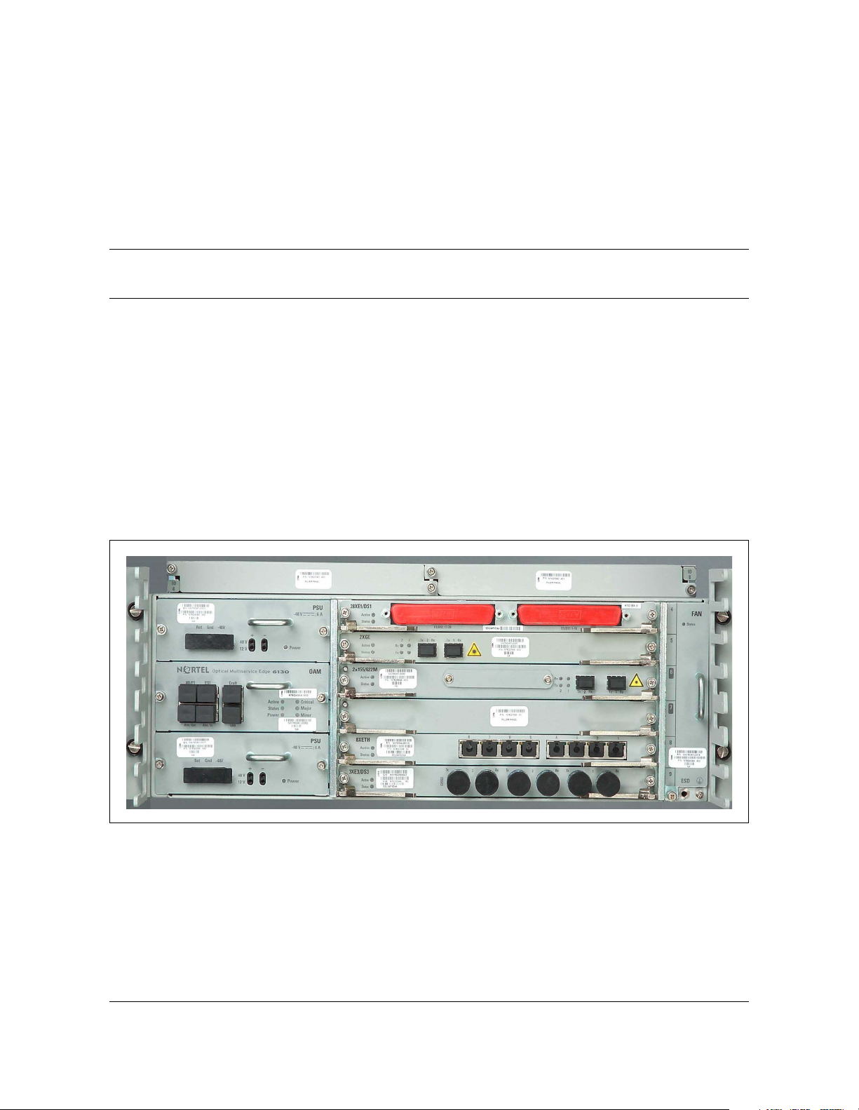
provided in the next release. Figure 1-1 displays the OME6130 network
element.
Figure 1-1
OME6130 network element
Planning Guide NT6Q92MA Rel 1.0 Iss 1 Standard September 2006

1-2 Introduction
The OME6130 provides dramatic cost savings over currently deployed
solutions and offers deployment flexibility at multiple levels, including:
• Service flexibility: Full mix of services including 10/100BT (Base-T)
Ethernet, Gigabit Ethernet, E1/DS1, E3/DS3 and STM-1o/e.
• Reach flexibility: Small Form-Factor Pluggable (SFPs) optics are used,
allowing each shelf to be configured for the distance and wavelength
required.
• Protection flexibility: Can be deployed with or without line protection.
Both 1+1 MSP and SNCP network protection protocols are supported.
• Interoperability flexibility: Can be networked either with other
OME6130 or OME6110 network elements, or subtended from other Nortel
optical products, such as OM4000 or OME6500.
• Management flexibility: The OME6130 is fully integrated into Nortel’s
Optical Application Platform with OMEA. The OME6130 can also be
managed from an HTTP web-based craft user interface running on the
network element. In addition, SNMP alarm traps are supported, enabling
OME6130 fault management from SNMP management systems.
• Data communications flexibility: The OME6130 can be managed over
either OSI or IP DCN networks. Path DCC capabilities are also provided
for extending management reach over third-party networks.
The OME6130 is a carrier grade platform that builds upon the solid reputation
for dependability of Nortel Networks' widely deployed optical networking
products. The various protection options offered by the OME6130 further
enhance the dependability of service transport. For access head end
applications, service traffic can either be connected via sub-network
connection protection (SNCP) or via protected point-to-point 1+1
connections.
Optical Multiservice Edge 6130 NT6Q92MA Rel 1.0 Iss 1 Standard September 2006

OME6130 applications
The OME6130 offers significant value across a range of network applications.
The principal OME6130 applications are:
• Feeder for Metro Optical networks: The OME6130 can be subtended
from Nortel’s larger Optical platforms to collect 10/100BT Ethernet,
Gigabit Ethernet, E1/DS1, E3/DS3 and STM-1o/e traffic from the Access
Edge. Its compact footprint and low price make it well suited for smaller
customer locations. The OME6130 can be subtended either in a SNCP or
1+1 MSP configuration. The capability to manage OME6130 using path
DCC bytes also allows it to be managed remotely over leased
STM-1/STM-4 circuits. The Regenerator Section and Multiplexer Section
overhead tunnel capability provides further flexibility in managing other
SDH equipment within the same ring.
• Private Enterprise Networks: The OME6130 can be deployed in smaller
private networks providing transport of 10/100BT Ethernet, Gigabit
Ethernet, E1/DS1, E3/DS3 and STM-1o/e services between sites. A light
weight management solution is available for such applications consisting
of a web-based craft interface running on the OME6130 for NE
provisioning and SNMP north bound interface for reporting alarms to a
generic SNMP alarm browser.
Introduction 1-3
• Wireless Backhaul: The OME6130 is also well suited for wireless
backhaul applications where both space and cost are paramount. The
OME6130 can be used as a cost-effective backhaul of today’s E1/DS1s and
will support the 3G network transition to Ethernet.
OME6130 service interfaces
OME6130 offers transport and aggregation of asynchronous private lines,
SDH, and Ethernet. The OME6130 shelf has four (4) universal tributary slots
and supports a full mix of tributary interfaces. The OME6130 supports three
basic categories of interface:
• 10/100BT (Base-T) Ethernet and Gigabit Ethernet
— The tributary slots can be equipped with the 8x10/100BT L1 Ethernet
and 2xGE L1 circuit packs. The 8x10/100BT L1 Ethernet circuit pack
supports 8 10/100 Base-T Ethernet Private Line (EPL) ports and the
2xGE L1 circuit pack supports 2 Gigabit Ethernet (GE) EPL ports.
• PDH
— The tributary slots can be equipped with the 28xE1/DS1 and 3xE3/DS3
circuit packs. The 28xE1/DS1 circuit pack supports 28 E1/DS1 ports
and the 3xE3/DS3 circuit pack supports 3 E3/DS3 ports.
•SDH
— The tributary slots can be equipped with the 2x155M circuit pack. The
2x155M circuit pack supports 2 STM-1 optical / electrical (o/e) ports.
Planning Guide NT6Q92MA Rel 1.0 Iss 1 Standard September 2006
1-4 Introduction
Small form-factor pluggable interfaces
The OME6130 uses small form-factor pluggable (SFP) interfaces to deliver
optical rate and reach flexibility on a per port basis for the line interface. The
OME6130 also supports electrical SFP for the STM-1e interface.
The OME6130 offers the following SFP interface types:
SR-0, I-1.1/I-4.1, S-1.1/S-4.1, L-1.1/L-4.1, L-1.2/L-4.2, CWDM, STM-1 BX,
STM-1e, GE SX and GE LX.
Nortel Networks has been collaborating closely with leading SFP vendors to
improve the reliability, robustness and manageability of SFPs. The use of such
carrier-grade SFP technology enables service providers to enjoy the flexibility
of provisioning the interfaces per the requirements of the specific application.
SFPs also reduce the cost of sparing by enabling an upgrade of the optical line
interfaces as they become readily available.
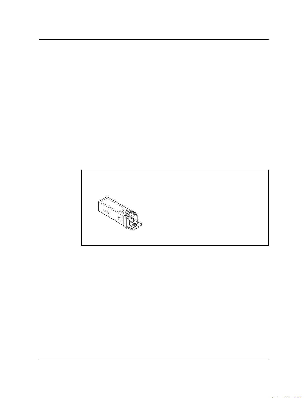
Figure 1-2
Pluggable optical modules summary
Small-form factor pluggable (SFP)
155/622/1000 Mbps
155/622 Mbit/s
- Carrier grade
- Service tolerance:
- Reach (SR/IR/LR)
- Rate (OC-3/STM-1, OC-12/STM-4 future)
- GE (future)
- CWDM with wavelength per pluggable slot
- Operational simplification
- Expenditure matched with reach requirements
- CAPEX savings through reduced sparing
Point-to-point optical broadband services
The OME6130 uses GFP, VCAT and LCAS standards for the mapping and
transport of Ethernet services.
GFP provides an efficient mechanism for Ethernet transport over a SDH core
network via efficiently mapping varying client signals into SDH VC-12, VC-3
and VC-4 frames. GFP mapping enables efficient network resource utilization
with low overhead requirements, and limited over-provisioning with VCAT.
End-to-end framing provides demarcation for the Ethernet signal, and enables
consistent SDH based PMs through the network. Since the Ethernet is mapped
into SDH frames, the existing core network can transport the Ethernet frames
transparently.
(STM-1/STM-4)
Optical Multiservice Edge 6130 NT6Q92MA Rel 1.0 Iss 1 Standard September 2006

Introduction 1-5
The OME6130 also supports Virtual Concatenation (ITU-T G.707 compliant)
with support at the VC-12-nv, VC-3-nv and VC-4-nv SDH rates. A maximum
of 48 ms of differential delay is supported.
Along with VCAT the OME6130 also supports value added capabilities such
as soft protection via Link Capacity Adjustment Scheme (LCAS - G.7042).
LCAS has been specifically developed to overcome static link provisioning. It
enables service providers to efficiently offer dynamically-allocated bandwidth
as well as hitless throttling of the capacity of a VCAT link (or Virtual
Concatenated Group) by adding or removing VCs as required.
LCAS provides a soft protection and load-sharing mechanism to automatically
decrease the link capacity if a VC path experiences a failure and automatically
increases the link capacity when the network fault is repaired. This capability
provides an extra level of network and service resiliency by facilitating the
support of SLAs through graceful service degradation when necessary. In
particular, during network and service restoration LCAS can support hitless
bandwidth expansion and contraction thereby reducing service interruptions in
the event of network failure and easing network operations and maintenance
actions.
TDM switching
In the OME6130 architecture, traffic is switched between working and
protection line interfaces via the switch matrix in the 2x155/622M aggregate
circuit pack.
All ingress service traffic is mapped into VC-11, VC-12, VC-3 or VC-4
containers and directed towards the switch matrix which is configured to
switch the incoming traffic to the appropriate line interface. The switch matrix
allows any input channel to be connected to any output channel. Hairpinning
is also supported between client ports.
Network management
The OME6130 is managed as an integral part of Nortel Networks' market
proven end-to-end optical portfolio management capabilities. This framework
supports a sophisticated and highly customizable desktop providing
centralized topology view and fault management, centralized launch pad for a
full suite of management applications, easy to use nodal managers and
seamless network element reach-through for Nortel Networks' complete
optical networks portfolio. These network management capabilities are
supported by the Optical Manager and Optical Application Platform, such as
OMEA and Optical Network Manager (formerly known as Preside), in
alignment with Nortel Networks overall optical networks portfolio.
Planning Guide NT6Q92MA Rel 1.0 Iss 1 Standard September 2006

1-6 Introduction
The OME6130 local craft access terminal, which is an HTTP web-based
graphical interface running on the network element, provides complete nodal
management that can be integrated into a centralized network wide view
through the Optical Application platform.
Key features and benefits
The OME6130 multi-services access platform provides customers with the
flexibility, scalability and management capabilities they need in a compact
cost effective package. The key benefits to customers of deploying the
OME6130 can be summarized as follows:
• support of a broad set of services (Ethernet, PDH/Async and SDH)
• switching granularity and flexibility for service grooming and connection
management, such as unconstrained VC-11 and VC-12 level switching
• cost-efficient service deployment through
— low cost entry configuration for E1/DS1 and E3/DS3 services
— in-service expansion to support new services
— dynamically pluggable optical and electrical SFP interfaces (lowers
sparing costs)
— flexible, complete and easy to use network and service management
leading to simplified operations for rolling out and maintaining
services
Optical Multiservice Edge 6130 NT6Q92MA Rel 1.0 Iss 1 Standard September 2006

2-1
Feature overview 2-
This chapter provides an overview of the Optical Multiservice Edge 6130
(OME6130) Release 1.0 supported features. Release 1.0 supports SDH optical
interfaces (STM-1/STM-4), electrical STM-1e interface as well as transport of
10/100 BT (Base-T) Ethernet, Gigabit Ethernet and PDH/DSn services.
OME6130 Release 1.0 supports the following features:
• SDH support
• hardware:
—chassis
— 2x155/622M aggregate circuit pack
— service interface circuit packs:
– 8x10/100BT L1 circuit pack
– 2xGE L1 circuit pack
– 28xE1/DS1 circuit pack
– 3xE3/DS3 circuit pack
– 2x155M circuit pack
— pluggable modules:
– SR-0, I-1.1/I-4.1, S-1.1/S-4.1, L-1.1/L-4.1, L-1.2/L-4.2 SFPs
– CWDM SFPs (8 wavelengths, 1470 nm to 1610 nm)
– STM-1 BX, STM-1e
– GE SX, LX
— redundant DC power supply units
— OAM circuit pack
— fan module
— filler faceplate
• System Line-Up and Test (SLAT) procedure
Planning Guide NT6Q92MA Rel 1.0 Iss 1 Standard September 2006

2-2 Feature overview
• configuration for the STM-1/STM-4 optical and STM-1e interfaces:
• connection management:
• service mappings:
—1+1 MSP
—SNCP
— unprotected
— VC-11, VC-12, VC-3, VC-4 cross-connects
— 10/100BT Ethernet GFP-F to VC-12, VC-3
— 10/100BT Ethernet GFP-F to VC-12-nv (n = 1 to 63), VC-3-nv (n = 1
to 3)
— Gigabit Ethernet GFP-F to VC-3, VC4
— Gigabit Ethernet GFP-F to VC-3-nv (n = 1 to 12) and VC-4-nv (n = 1
to 4)
— E1 to VC-12
— E3 to VC3
—DS1 to VC-11
—DS3 to VC3
Note: Only low order VC3/TU3/AU4 mapping is supported
• synchronization:
—SSM
— E1 BITS synchronization
— line timing
— port (E1 facility)
• fault management:
— alarm reporting control
— regenerator section alarms
— multiplex section alarms
— high order path alarms
— low order path alarms
— E1/E3/DS1/DS3 alarms
— 10/100BT Ethernet and Gigabit Ethernet alarms
• performance monitoring:
— SDH regenerator section, multiplex section PM parameters
— high order path PM parameters
Optical Multiservice Edge 6130 NT6Q92MA Rel 1.0 Iss 1 Standard September 2006

— low order path PM parameters
— E1/E3/DS1/DS3 PM parameters
— 10/100BT Ethernet and Gigabit Ethernet PM parameters
•DCN:
— OA&M over D1-D3 and F1 RS bytes
— OA&M over D4-D9 MS bytes
— OA&M over F2, F3 & F2F3 path overhead bytes
— overhead tunnel with RS, MS, E1, E2, F1 bytes
— E1/VC12 management channel
— F1 byte user channel access
— PPP/LAPD over DCC
— OSPF routing
— iISIS routing
— Auto GRE tunnels
— Proxy ARP
Feature overview 2-3
• web user interface (WUI):
— Microsoft Internet Explorer 6.0 or higher
— Mozilla 1.6 & 1.7 on Red Hat Linux, HP-UX and Solaris
— FireFox 1.0 on Red Hat Linux 7.x
• SNMP v1 and v2 trap monitoring
• interworking:
— subtending 1+1 MSP or multi-node SNCP from:
– Optical Metro 4100/4150/4200
– Optical Multiservice Edge 6500
– Optical Multiservice Edge 6110
— co-existing on rings:
– TN-1C/1X
Table 2-1 lists the features available in the Optical Multiservice Edge 6130.
For more information about these features, refer to the appropriate reference
in this planning guide. The following sections in this chapter give a brief
description of the main features.
Planning Guide NT6Q92MA Rel 1.0 Iss 1 Standard September 2006

2-4 Feature overview
Table 2-1
Summary of features for current releases
Topic OME6130
Reference
R1.0
OME6130 hardware
Chassis Yes Chassis on page 4-3
2x155/622M Aggregate circuit pack Yes 2x155/622M aggregate circuit pack
on page 4-8
Single feed DC power supply unit Yes DC Power supply unit on page 4-4
Fan module Yes Fan module on page 4-5
OAM unit Yes OAM circuit pack on page 4-6
Filler faceplate Yes Filler faceplate on page 4-18
75 ohm termination panel Yes E1 75 ohm termination panel on page
4-18
Tributary interface circuit packs
8x10/100BT L1 Yes
2xGE L1 Yes
Tributary interface circuit pack
28xE1/DS1 Yes
descriptions on page 4-10
3xE3/DS3 Yes
2x155M Yes
SFP modules
STM-1 SR-0 1310 nm Yes
STM-1/4 S-1.1/S-4.1 1310 nm Yes
STM-1/4 L-1.1/L-4.1 1310 nm Yes
STM-1/4 L-1.2/L-4.2 1550 nm Yes
Small form-factor pluggable (SFP)
modules on page 8-10
STM-1/4 CWDM, STM-1 BX, STM-1e Yes
GE SX, LX Yes
Configurations
1+1 MSP Yes 1+1 MSP on page 3-1
SNCP Yes SNCP on page 3-1
Unprotected Yes Unprotected configuration on page
3-2
Optical Multiservice Edge 6130 NT6Q92MA Rel 1.0 Iss 1 Standard September 2006

Table 2-1 (continued)
Summary of features for current releases
Feature overview 2-5
Topic OME6130
R1.0
Equipment and facility management
Equipment management Yes Equipment management on page 6-3
Facility Management Yes Facility management on page 6-4
Connection management
VC11, VC12, VC3 and VC4 cross-connects Yes Connection management on page
Service Mapping
10/100BT Ethernet
10/100BT Ethernet
GFP-F to VC12, VC3 Yes
GFP-F to VC12-nv, VC3-nv
Yes
(virtual concatenation)
Gigabit Ethernet
Gigabit Ethernet
GFP-F to VC3, VC4 Yes
GFP-F to VC3-nv, VC4-nv
Yes
Reference
6-13
Generic Framing Procedure on page
6-14
(virtual concatenation)
E1 to VC12 Yes
DS1 to VC11 Yes
E3 to VC3 Yes
Connection management application
on page 6-15
DS3 to VC3 Yes
Traffic protection
MSP - STM-1/4 Yes 1+1 MSP traffic protection on page
6-18
SNCP Yes SNCP Traffic Protection on page
6-20
Unprotected - STM-1/4 Yes Unprotected connections on page
6-21
Synchronization
Internal, BITS, line, port Yes
Timing generation hierarchy Yes
Timing distribution hierarchy Yes
SDH SSM generation/termination Yes
2 MHz and 2 Mbits/s ESI/ESO with SSM Yes
Planning Guide NT6Q92MA Rel 1.0 Iss 1 Standard September 2006
Synchronization management on
page 6-7

2-6 Feature overview
Table 2-1 (continued)
Summary of features for current releases
Topic OME6130
Reference
R1.0
Alarms and events
LEDs indication of shelf and circuit pack status Yes
Alarm and event reporting Yes
Alarm reporting control Yes
Alarm and event management on
page 6-27
RS, MS, HO path, LO path alarms Yes
STM-1/4, E1/DS1, E3/DS3 alarms Yes
Performance monitoring
SDH RS, MS and path Yes
Transceiver (physical PM for SFPs) Yes
Ethernet and VCG Yes
Performance monitoring on page
6-32
E1/DS1/E3/DS3 PM parameters Yes
System lineup and testing
SLAT (commissioning tool) Yes System Line-up and Test (SLAT) on
page 6-2
Loopbacks
Facility and Terminal Loopbacks
(STM-1/4, E1, DS1, E3, DS3, GE)
Yes
Loopbacks on page 6-6
Terminal Loopback (10/100 BT Ethernet) Yes
Data management
NE data backup and restore Yes Backing up and restoring the network
element database on page 6-42
Security and administration
Local user account/password management Yes Security and administration on page
Network element naming, date and time Yes
6-38
Topology Adjacency
Topology adjacency provisioning and discovery Yes Topology adjacency on page 6-41
Data communication network
Optical Multiservice Edge 6130 NT6Q92MA Rel 1.0 Iss 1 Standard September 2006

Table 2-1 (continued)
Summary of features for current releases
Feature overview 2-7
Topic OME6130
Reference
R1.0
LAN, DCC physical interfaces Yes
IP addressing Yes
OSI addressing Yes
Enable/disable OSPF per network interface Yes
IP over OSI GRE tunnel (auto or static) Yes
PPP/LAPD over DCC Yes
Data communications on page 6-22
and Appendix A: Data
communications planning on page
10-1
iISIS routing Yes
Proxy ARP Yes
F1 user channel access Yes
OAM via Path DCC (F2/F3 bytes) Yes
E1/VC12 management channel Yes
OME6130 management
Web User Interface Yes User interface description on page
5-1
SNMP v1 and v2 trap monitoring Yes
Interworking
Nortel portfolio Yes Interworking with Nortel portfolio on
page 2-16
non-Nortel portfolio Yes Interoperating with non-Nortel
portfolio on page 2-16
Planning Guide NT6Q92MA Rel 1.0 Iss 1 Standard September 2006
2-8 Feature overview
Physical description
The OME6130 hardware platform consists of a chassis which fits in a standard
19 in., 21 in., or 23 in. rack. The chassis is equipped with the following circuit
packs:
• one 2x155/622M aggregate circuit pack
• up to 4 service interfaces:
– 8x10/100BT L1 circuit pack
– 2xGE L1 circuit pack
– 28xE1/DS1 circuit pack
– 3xE3/DS3 circuit pack
– 2x155M circuit pack
• two single feed DC power supply unit
• OAM circuit pack
• fan module
• filler faceplate
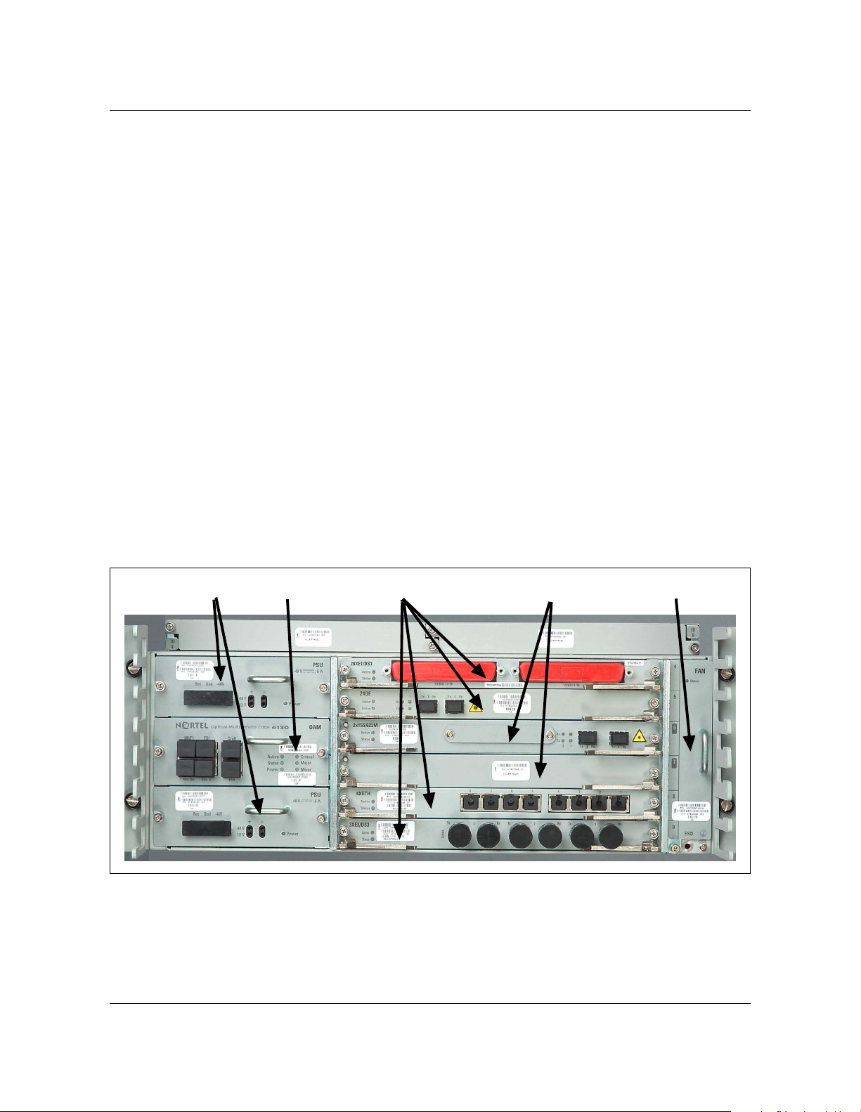
Figure 2-1 provides an overview of the OME6130 chassis layout.
Figure 2-1
OME6130 chassis layout
PSU (2)
For more information, refer to “Hardware description” on page 4-1 and
“OME6130 network element configuration rules” on page 8-2.
OAM
Tributary slots (4)
Aggregate slots (2)
Fan
Optical Multiservice Edge 6130 NT6Q92MA Rel 1.0 Iss 1 Standard September 2006

Interface circuit packs
The OME6130 Release 1.0 supports one 2x155/622M aggregate circuit pack
where two STM-1 or STM-4 line interfaces are present. The OME6130 also
supports four tributary slots that can be equipped with the following circuit
packs:
• 8x10/100BT L1 circuit pack
• 2xGE L1 circuit pack
• 28xE1/DS1 circuit pack
• 3xE3/DS3 circuit pack
• 2x155M circuit pack
Note: When the tributary slots are not equipped with a circuit pack, a filler
panel must be installed.
Table 2-2 provides a summary of the tributary circuit packs supported in
OME6130 Release 1.0.
Table 2-2
OME6130 tributary circuit pack summary
Feature overview 2-9
Circuit pack Port density/
circuit pack
8x10/100BT L1
2xGE L1
28xE1/DS1
3xE3/DS3
2x155M
8
2
28
3
2
Notes
• GFP-F mapped (ITU-T G.7041
compliant)
• GFP-F mapped (ITU-T G.7041
compliant)
• unframed E1
• CRC4 framed E1
• unframed DS1
• ESF DS1
• unframed E3
• G.832 framed E3
• unframed DS3
• ASYNC framed DS3
• STM-1 optical and electrical SFPs
supported
For more information about the tributary circuit packs, refer to Tributary
interface circuit pack descriptions on page 4-10. For more information about
slot equipping rules, refer to Chassis layout on page 8-2.
Planning Guide NT6Q92MA Rel 1.0 Iss 1 Standard September 2006

2-10 Feature overview
System Line-up and Test (SLAT)
This release supports the ability to configure the system when it is being
commissioned for the first time. The user is given an option to initialize the
system with a configuration compatible with the NE.
The node capability is provisioned to either STM-1 or STM-4 during initial
commissioning. The two SFP interfaces of the 2x155/622M aggregate circuit
pack are operating at the rate of the node capability value.
For more information, refer to System Line-up and Test (SLAT) on page 6-2
Configurations
OME6130 currently supports the following configurations for the STM-1/4
line interfaces.
1+1 MSP protection
OME6130 supports 1+1 Multiplex Section Protection (MSP) configurations.
For more information, refer to 1+1 MSP on page 3-1.
SNCP
OME6130 supports Sub-network connection protection (SNCP) ring
configurations.
In a SNCP configuration, traffic is transmitted simultaneously on two separate
ports. The traffic is transmitted via different routes through the network to the
destination node which selects one of the two paths based on the quality of the
received signal. For example, in a ring configuration, the traffic can be
transmitted simultaneously on the working fiber in the clockwise direction and
on the protection fiber in the counter-clockwise direction.
For more information, refer to SNCP on page 3-1.
Unprotected
OME6130 supports unprotected configurations. For more information, refer to
Unprotected configuration on page 3-2.
Optical Multiservice Edge 6130 NT6Q92MA Rel 1.0 Iss 1 Standard September 2006

Connection management
OME6130 supports nodal port-to-port connection management. OME6130
supports the ability to provision bidirectional and unidirectional connections
at VC11, VC12, VC3, and VC4 rates.
OME6130 Release 1.0 supports various bandwidth management models that
include the following;
• bidirectional connections
• unidirectional connections
• port to port (hair-pinning)
• drop and continue
Note: Only bidirectional connection type is supported for WAN ports
corresponding to the 10/100BT Ethernet and Gigabit Ethernet ports.
For more information, refer to Connection management on page 6-13.
Service mapping
All services (Ethernet, E1, DS1, E3, and DS3) are mapped to appropriate SDH
containers.
Feature overview 2-11
The OME6130 uses Generic Framing Procedure (GFP) as its standards based
SDH mapping for Ethernet services. GFP is an ITU standard (G.7041) which
describes a flexible mapping technique for transparent transport of multiple
protocols in SDH. GFP-Framed (GFP-F) is used for mapping Ethernet to SDH
tributaries and containers.
Table 2-3 provides a summary of the service mappings supported in this
release.
Table 2-3
OME6130 service mapping
Services Circuit Pack Mapping/connection level
supported
10/100BT Ethernet
Gigabit Ethernet
E1/DS1
E3/DS3
• 8x10/100BT L1 • GFP-F to VC12, and VC3
• 2xGE L1 • GFP-F to VC3, and VC-4
• 28xE1/DS1 • VC12, VC11
•3xE3/DS3 •VC3
For more information, refer to Connection management on page 6-13.
Planning Guide NT6Q92MA Rel 1.0 Iss 1 Standard September 2006

2-12 Feature overview
Traffic protection
OME6130 supports 1+1 MSP and SNCP traffic protection. The system
monitors the traffic facilities for performance degradation and failure and
performs protection switching when these conditions are present. Table 2-4
provides a summary of the protection schemes supported in this release.
Table 2-4
Traffic protection summary
Protection scheme Supported interfaces or circuit packs
1+1 MSP • STM-1/4 interfaces
SNCP • STM-1/4 interfaces
• 8x10/100BT L1 circuit pack
• 2xGE L1 circuit pack
• 28xE1/DS1 circuit pack
• 3xE3/DS3 circuit pack
Unprotected
(default for all supported
interfaces)
For more information, refer to Traffic protection on page 6-17.
Synchronization
Synchronization is a network level application that ensures all nodes across a
network can trace back to the same clock source. Within a single node,
synchronization prevents buffer overflow or underflow which avoids bit
errors.
For more information, refer to Synchronization management on page 6-7.
Alarms and events
The OME6130 provides several mechanisms to identify and localize faults and
events.
• light-emitting diodes (LEDs) on the faceplate of a circuit pack indicate the
status of the functionality supported on the equipment
• STM-1/4 interfaces
• 8x10/100BT L1 circuit pack
• 2xGE L1 circuit pack
• 28xE1/DS1 circuit pack
• 3xE3/DS3 circuit pack
— circuit pack failed on all circuit packs
— loss of signal on interface circuit packs
— power LED on the OAM circuit pack provides the power status
Optical Multiservice Edge 6130 NT6Q92MA Rel 1.0 Iss 1 Standard September 2006
 Loading...