

Page 1

Nortel Remote Agent Observe
Planning, Installation and Administration Guide
Document Version 1.2 Jan 2007
Page 2

Nortel Proprietary
Nortel Remote Agent Observe
Planning, Installation and Administration Guide
Document Version: 1.2
Release Date: Jan 10
th
2007
Copyright © 2007 Nortel Networks, All Rights Reserved.
Information is subject to change without notice. Nortel Networks reserves the right to make changes in
design or components as progress in engineering and manufacturing may warrant.
Planning, Installation and Administration Guide
2
Page 3

Nortel Proprietary
Revision History
Jan 10th 2007 Version 1.2 is released. Changed switch port
configuration to using hunt groups instead of mcr key.
Changed all reference from Nortel Networks to Nortel.
Changed description re RSM rate change. Updated
PEC/CPC codes used in guide to RoHS compliant
codes.
Sep 21st, 2004 Version 1.1 is released. Added section re Voice Prompt
Level Regulatory Requirements to 6.6 TUI Language
Administration.
Feb 10th, 2004 Version 1.0. GA version is released.
Planning, Installation and Administration Guide
3
Page 4

Nortel Proprietary
Table of Contents
1 GETTING STARTED.....................................................................................................................9
1.1 OVERVIEW..................................................................................................................................... 9
1.2 WHO SHOULD READ THIS GUIDE.........................................................................................................9
1.3 ABOUT NORTEL REMOTE AGENT OBSERVE........................................................................................ 9
1.4 SCCS VERSIONS PREVIOUS TO VERSION 4.2........................................................................................9
2 INSTALLING THE NORTEL REMOTE AGENT OBSERVE CARD.................................. 11
2.1 INSTALLATION OVERVIEW ............................................................................................................. 11
2.2 SWITCH CAPACITY RULES.............................................................................................................. 12
2.3 INSTALLING THE NORTEL REMOTE AGENT OBSERVE CARD.................................................................13
3 CONFIGURATION OF NORTEL REMOTE AGENT OBSERVE CARD........................... 16
3.1 CABLING THE NORTEL REMOTE AGENT OBSERVE CARD.................................................................... 16
3.2 NETWORK SETTINGS......................................................................................................................21
3.3 ASSIGNING THE INTERNET PROTOCOL (IP) ADDRESS..........................................................................23
3.4 CHANGING THE USERNAME AND PASSWORD FOR COMMAND LINE ACCESS................................................ 26
3.5 SWITCH CONFIGURATION FOR NORTEL REMOTE AGENT OBSERVE....................................................... 27
3.6 FTP CONFIGURATION....................................................................................................................35
4 PREPARING THE SYMPOSIUM CALL CENTRE SERVER............................................... 36
4.1 OVERVIEW................................................................................................................................... 36
4.2 MODIFYING REAL-TIME STATISTICS MULTICAST SETTINGS.................................................................. 37
4.3 TESTING THE REAL-TIME STATISTICS MULTICAST SERVICE.................................................................. 43
5 USING THE BROWSER USER INTERFACE ........................................................................ 45
5.1 BROWSER USER INTERFACE ACCESS GUIDELINES.............................................................................. 45
5.2 ACCESSING THE BUI.....................................................................................................................46
5.3 CONFIGURING THE CARD................................................................................................................48
5.4 CREATION OF OBSERVER ACCOUNTS................................................................................................52
5.5 MODIFICATION OF OBSERVER ACCOUNTS......................................................................................... 55
5.6 REMOVAL OF OBSERVER ACCOUNTS................................................................................................58
5.7 DISPLAY OF ACCOUNTS................................................................................................................. 61
5.8 OBSERVATION PARAMETERS CREATION/REMOVAL............................................................................. 63
5.9 SYMPOSIUM NAME TO ID MAPPING ............................................................................................... 66
5.10 OBSERVATION PARAMETERS SYNONYM ASSIGN...............................................................................67
5.11 BACKUP/RESTORE.......................................................................................................................69
5.12 ADMINISTRATION PASSWORD........................................................................................................ 70
5.13 OBSERVER REPORTING ................................................................................................................71
5.14 CARD RESET.............................................................................................................................. 73
6 USING THE TELEPHONY USER INTERFACE.....................................................................75
6.1 ACCESSING THE TELEPHONY USER INTERFACE ................................................................................. 75
6.2 QUICK REFERENCE CARD...............................................................................................................75
6.3 TUI AUTHENTICATION.................................................................................................................. 76
6.4 ADMINISTRATOR TUI MENU..........................................................................................................78
6.5 OBSERVER TUI MENU..................................................................................................................79
6.6 TUI LANGUAGE ADMINISTRATION.................................................................................................. 86
6.7 TELEPHONY USER INTERFACE MENU FLOWS.................................................................................... 91
7 CALL RECORDING.................................................................................................................. 100
7.1 INTRODUCTION............................................................................................................................100
7.2 CALL RECORDING CONFIGURATION AND OPERATION........................................................................100
7.3 CALL RECORDING FILE FORMAT................................................................................................... 100
8 ENGINEERING GUIDELINES ............................................................................................... 102
Planning, Installation and Administration Guide
4
Page 5

Nortel Proprietary
8.1 INTRODUCTION............................................................................................................................102
8.2 DYNAMIC MEMORY SIZE LIMITS...................................................................................................102
8.3 PCMCIA CARD MEMORY SIZE LIMITS........................................................................................103
8.4 USAGE GUIDELINES.....................................................................................................................104
9 TEST AND DEBUG CAPABILITIES..................................................................................... 105
9.1 INTRODUCTION............................................................................................................................105
9.2 SELF TEST FEATURES.................................................................................................................. 106
9.3 FACTORY TEST FEATURES............................................................................................................107
9.4 VXWORKS SHELL.......................................................................................................................110
9.5 CARD STATE DEBUG UTILITIES.................................................................................................... 111
9.6 APPLICATION LEVEL DEBUGGING ................................................................................................. 112
9.7 TROUBLESHOOTING RSM PARSING............................................................................................... 114
10 UPGRADE PROCEDURES.....................................................................................................119
10.1 APPLICATION LOADWARE UPGRADE ............................................................................................119
10.2 XA FIRMWARE UPGRADE ........................................................................................................ 123
10.3 BOOTROM LOADWARE UPGRADE..............................................................................................125
11 GLOSSARY............................................................................................................................... 127
12 APPENDIX.................................................................................................................................128
12.1 PRECAUTIONS FOR HANDLING CIRCUIT CARDS.................................................................................128
12.2 SAMPLE BOOT-UP SEQUENCE....................................................................................................... 130
12.3 TUI PROMPT LIST....................................................................................................................133
12.4 SWITCH CONFIGURATION CHANGE ..............................................................................................135
Planning, Installation and Administration Guide
5
Page 6

Nortel Proprietary
List of Figures
FIGURE 1 MEDIA CARD LAYOUT........................................................................................... 16
FIGURE 2 NORTEL REMOTE AGENT OBSERVE CARD ADAPTER CLAN (L-
ADAPTER)........................................................................................................................................18
FIGURE 3 L-ADAPTER AND FILTER BLOCK CONNECTION SETUP ON LARGE
SYSTEMS..........................................................................................................................................19
FIGURE 4 HUNTING FOR IDLE TUI PORTS...........................................................................28
FIGURE 5 SAMPLE LD11 TUI PORT SWITCH CONFIGURATION................................... 30
FIGURE 6 OBSERVE PORT SWITCH CONFIGURATION................................................... 33
FIGURE 7 LD 32 ENABLE NORTEL REMOTE AGENT OBSERVE UNIT.........................33
FIGURE 8 SAMPLE LD32 STATUS OUTPUT.......................................................................... 34
FIGURE 9 RTD MULTICAST CONTROLLER SCREEN....................................................... 38
FIGURE 10 RTD MULTICAST CONFIGURATION SCREEN...............................................39
FIGURE 11 BUI INTRODUCTION PAGE (NON-SCCS)......................................................... 46
FIGURE 12 BUI INTRODUCTION PAGE (SCCS)....................................................................47
FIGURE 13 SCCS CONFIGURATION PAGE........................................................................... 48
FIGURE 14 NON-SCCS CONFIGURATION PAGE................................................................. 49
FIGURE 15 SCCS OBSERVER ACCOUNT CREATION PAGE.............................................52
FIGURE 16 NON-SCCS OBSERVER ACCOUNT CREATION PAGE.................................. 53
FIGURE 17 OBSERVER ACCOUNT MODIFY SELECTION PAGE.................................... 55
FIGURE 18 SCCS OBSERVER ACCOUNT MODIFY PAGE................................................. 56
FIGURE 19 NON-SCCS OBSERVER ACCOUNT MODIFY PAGE....................................... 56
FIGURE 20 OBSERVER ACCOUNT REMOVE PAGE........................................................... 58
FIGURE 21 OBSERVER ACCOUNT REMOVAL PAGE........................................................ 59
FIGURE 22 OBSERVER ACCOUNT REMOVAL CONFIRM PAGE.................................... 60
FIGURE 23 OBSERVER ACCOUNT DISPLAY SELECTION PAGE................................... 61
FIGURE 24 OBSERVER ACCOUNT DISPLAY PAGE............................................................62
FIGURE 25 OBSERVATION PARAMETERS SELECTION PAGE.......................................63
FIGURE 26 OBSERVATION PARAMETERS MODIFY/REMOVAL PAGE....................... 64
FIGURE 27 BUI SYNONYM PARAMETER SELECTION PAGE..........................................67
FIGURE 28 BUI SYNONYM ASSIGNMENT PAGE.................................................................68
FIGURE 29 BUI BACKUP/RESTORE PAGE............................................................................ 69
FIGURE 30 BUI ADMINISTRATOR PASSWORD MODIFY PAGE..................................... 70
FIGURE 31 BUI OBSERVER ACTIVITY LOGGING PAGE.................................................. 71
FIGURE 32 OLDER REPORTS MESSAGE DISPLAY............................................................ 72
FIGURE 33 BUI CARD RESET PAGE........................................................................................73
FIGURE 34 EXAMPLE OF MULTIPLE FILE TRANSFER USING FTP..............................90
FIGURE 35 TUI LOGIN MENU................................................................................................... 92
Planning, Installation and Administration Guide
6
Page 7

Nortel Proprietary
FIGURE 36 SCCS MAIN MENU.................................................................................................. 93
FIGURE 37 AGENT ID SELECT MENU (SIMILAR STRUCTURE - POSITION ID
SELECT MENU)..............................................................................................................................94
FIGURE 38 AGENT ID OBSERVE MENU (SIMILAR STRUCTURE - POSITION ID
OBSERVE MENU)...........................................................................................................................95
FIGURE 39 SKILLSET SELECT MENU (SIMILAR STRUCTURE - APPLICATION,
CDN, DNIS SELECT MENUS)...................................................................................................... 96
FIGURE 40 SKILLSET OBSERVE MENU ( SIMILAR STRUCTURE -APPLICATION,
CDN AND DNIS OBSERVE)..........................................................................................................97
FIGURE 41 NON SCCS AND PRE RELEASE 4.2 SCCS MAIN MENU.................................98
FIGURE 42 NON SCCS AND PRE RELEASE 4.2 SCCS OBSERVE MENU.........................99
FIGURE 43 CALL RECORDING FILENAME – AMERICAN DATE FORMAT...............101
FIGURE 44 CALL RECORDING FILENAME – EUROPEAN DATE FORMAT...............101
FIGURE 45 DISABLING THE NORTEL REMOTE AGENT OBSERVE CARD USING
OVERLAY 32................................................................................................................................. 104
FIGURE 46 ENABLING THE NORTEL REMOTE AGENT OBSERVE CARD USING
OVERLAY 32................................................................................................................................. 104
FIGURE 47 RSM ERROR MESSAGE ON INTRODUCTION PAGE...................................114
FIGURE 48 SAMPLE BOOT-UP SEQUENCE.........................................................................132
FIGURE 49 HUNTING FOR IDLE TUI PORTS.......................................................................137
FIGURE 50 PRINTING TUI PORT SWITCH CONFIGURATION IN OVERLAY 20........139
FIGURE 51 DISABLING THE NORTEL REMOTE AGENT OBSERVE CARD SLOT
USING OVERLAY 32....................................................................................................................139
FIGURE 52 REMOVING TUI PORTS USING OVERLAY 11................................................139
FIGURE 53 DISPLAYING A LIST OF UNUSED DNS IN OVERLAY 20............................. 139
FIGURE 54 SAMPLE CONFIGURATION FOR TUI PORTS................................................ 140
FIGURE 55 CONFIGURING TUI PORTS FROM OVERLAY 11..........................................141
FIGURE 56 ENABLING THE NORTEL REMOTE AGENT OBSERVE CARD SLOT
USING OVERLAY 32....................................................................................................................141
FIGURE 57 DISPLAYING CONFIGURED PORTS FROM OVERLAY 32..........................141
FIGURE 58 NORTEL REMOTE AGENT OBSERVE TUI PORT CONFIGURATION
DETAILS.........................................................................................................................................142
List of Tables
TABLE 1 CALL-CENTRE OBSERVATION PARAMETERS.................................................... 9
TABLE 2 NORTEL REMOTE AGENT OBSERVE APPLICABILITY AND
COMPATIBILITY...........................................................................................................................12
TABLE 3 NORTEL REMOTE AGENT OBSERVE SWITCH CAPACITY RULES..............12
TABLE 4 PRE-INSTALL CHECKLIST FOR NORTEL REMOTE AGENT OBSERVE......13
TABLE 5 NORTEL REMOTE AGENT OBSERVE PRODUCT STRUCTURE..................... 16
TABLE 6 MODEM SETTINGS..................................................................................................... 20
Planning, Installation and Administration Guide
7
Page 8

Nortel Proprietary
TABLE 7 TCP/UDP PORTS USED............................................................................................... 22
TABLE 8 LD11 NORTEL REMOTE AGENT OBSERVE TUI PORT CONFIGURATION. 29
TABLE 9 LD23 NORTEL REMOTE AGENT OBSERVE ACD QUEUE CONFIGURATION
............................................................................................................................................................ 31
TABLE 10 LD11 NORTEL REMOTE AGENT OBSERVE OBSERVATION PORT
CONFIGURATION......................................................................................................................... 31
TABLE 11 OBSERVER ACCOUNT PARAMETER EXPLANATION.................................... 54
TABLE 12 REPORTING LOG-FILE EXPLANATION............................................................. 71
TABLE 13 HEX DISPLAY CODES DURING BOOT-UP........................................................ 107
TABLE 14 HEX DISPLAY ERROR CODES............................................................................. 108
TABLE 15 FACEPLATE CONNECTOR MINI-DIN CONNECTOR PIN-OUT................... 109
TABLE 16 VXWORKS SHELL CARD STATE DEBUG UTILITIES....................................111
TABLE 17 TASK LOGGING COMMANDS..............................................................................112
Planning, Installation and Administration Guide
8
Page 9

Nortel Proprietary
1 Getting Started
1.1 Overview
The Nortel Remote Agent Observe Planning, Installation and Administration
Guide will provide step-by-step instructions you must perform to complete the
installation and administration of Nortel Remote Agent Observe.
1.2 Who should read this guide
This guide is intended for
Nortel installers and distributors who are responsible for installing Nortel Remote
Agent Observe.
Administrators who are responsible for monitoring and maintaining Nortel Remote
Agent Observe.
1.3 About Nortel Remote Agent Observe
Nortel Remote Agent Observe allows supervisors and observers to remotely
observe and record agent calls without having to install any physical equipment at
the observer’s location.
Nortel Remote Agent Observe allows for observation by agent specific parameters
such as Position ID and Agent ID as well as observation by Symposium Call
Center Server parameters (SCCS) such as skillset ID, DNIS, Application ID and
CDN.
Nortel Remote Agent Observe is specifically designed to operate with SCCS
versions 4.2, 5.0 and later. It can be deployed in non-SCCS call centers and with
earlier SCCS versions, but in these cases only observe by position ID functionality
is available and call recording is not supported.
Call Centre Type SCCS 4.2 SCCS 5.0 Non SCCS (including pre-
release 4.2 SCCS servers)
Observe
Functionality
Available
Agent ID
Skillset ID
Position ID
Agent ID
Skillset ID
DNIS
Application ID
CDN
Position ID
Call Recording
Supported
Yes Yes No
Table 1 Call-Centre Observation Parameters
1.4 SCCS versions previous to version 4.2
Nortel Remote Agent Observe requires the RSM stream from the SCCS server in
order to allow for observation by Agent ID, skillset ID, DNIS, Application ID and
CDN.
Planning, Installation and Administration Guide
9
Page 10

Nortel Proprietary
Nortel Remote Agent Observe is not designed to accept an RSM stream from pre
4.2 versions of SCCS. Hence, the functionality available from Nortel Remote
Agent Observe with pre 4.2 versions of SCCS is similar to that available for nonSCCS call centers.
In pre 4.2 SCCS call centers, the card must be configured to operate as non-SCCS.
Throughout this document, any reference to Nortel Remote Agent Observe
operation with non-SCCS call centers also applies to pre 4.2 versions of SCCS.
Planning, Installation and Administration Guide
10
Page 11

Nortel Proprietary
2 Installing the Nortel Remote Agent
Observe Card
2.1 Installation Overview
Table 2 outlines installation information for the card.
Nortel Remote Agent
Observe
Application and Compatibility
Switch Options Small systems:
Option 11 Cabinet / Chassis;
Succession 1000;
Succession 1000M Cabinet / Chassis.
Large Systems:
Option 51C/61C/81/81C
Succession 1000M Half Group/Single Group/Multi Group
Card Slot location Option 51C,61C, 81 or 81C: any IPE slot except CONT
Any IPE slot in an Option 11 Cabinet / Chassis.
Succession 1000M Half Group / Single Group / Multi Group: any IPE
slot except CONT.
Any IPE slot in a Succession 1000 or Succession 1000M Cabinet /
Chassis.
Note: On older Option 51C to 81C systems (before IPE shelf vintage
NT8D37ECE5) slots other than 0,4,8,12 will require the NT8D81AAE6
Backplane to I/O Panel Cable to be installed to connect all required
signals to I/O panel.
MDF Cabling None ( the sets are virtual)
LAN Cabling Complete Cabling Requires:
1 NTAG81CAE6 PC Maintenance Cable
50 pin I/O Connector -A0852632
NTVQ83AAE6 ITG EMC Shielding Kit
1 Category 5,100-Base-T Ethernet standard
Software Release Meridian 1 Rls 25.15 software and later.Succession Rls 2.0 and later
Dip Switches Setting None
Time & Date stamp Automatically sent out by M1 CPU
Upgrade Capability Yes, loadware upgrades invoked from Maintenance CLI. Upgrade
across network via FTP.
Recording Storage If Call Recording is chosen the FTP Server being used must have
adequate file storage space:
A 1 minute recording of a call takes up about 480KB.
Conference capacity Each Nortel Remote Agent Observe Session will use 3 conference
ports on the switch.
If OBTN is either AGENT or ALL, each Nortel Remote Agent Observe
Session will use 4 conference ports on the switch.
If Agent Greeting is being used and OBTN is either AGENT or ALL,
each Nortel Remote Agent Observer Port will use 5 conference ports
on the switch.
It is the responsibility of the switch administrator to ensure that
there are enough conference ports on the switch to handle the
number of simultaneous observes permitted by the Nortel Remote
Agent Observe keycode and that each agent has enough
conference capacity assigned to allow for usage by Nortel Remote
Agent Observe, Agent Greeting, OBTN and personal conference
activities.
Planning, Installation and Administration Guide
11
Page 12

Nortel Proprietary
PEP Information To inter-operate with Agent Greeting the following PEP must be
applied: MPLR17930
Table 2 Nortel Remote Agent Observe Applicability and compatibility
2.2 Switch Capacity Rules
The following table shows the maximum number of Nortel Remote Agent Observe
Cards that can be installed in each type of switch.
Switch Type QTY
Small systems:
Option 11 Cabinet / Chassis.
Succession 1000.
Succession 1000M Cabinet / Chassis
1
Large Systems:
Option 51C/61C/81/81C.
Succession 1000M Half Group/Single Group/Multi Group
3
Table 3 Nortel Remote Agent Observe Switch Capacity Rules
Planning, Installation and Administration Guide
12
Page 13
Nortel Proprietary
2.3 Installing the Nortel Remote Agent Observe Card
Pre-Install checklist
To allow for successful installation the Nortel Remote Agent Observe Card, the
administrator must ensure the requirements listed in the pre-install checklist (Table
4) below have been met.
Requirements for Nortel Remote Agent Observe Installation.
Nortel Remote Agent Observe Installation Pack (see Table 5).
RS232 Maintenance Cable for access to the card’s command prompt.
Access to switch software (with administrator privileges) so card can be
configured at switch level.
Free slot in switch where card can be installed.
IP configuration for the card: Card IP Address, Gateway IP Address and
Subnet Mask.
(see section “Assigning the Internet Protocol (IP” on page 23).
Keycode for the card (This is shipped with the Installation Pack).
Browser to access the card (IE 5.5 or 6.0), Netscape 7.0
If Using SCCS server (post release 4.2):
Multicast IP address of SCCS server
Multicast Agent-Moving window port of SCCS server
IP address of the SCCS server
If configuring call recording:
FTP server with accounts set up for Nortel Remote Agent Observe. These
accounts must have write and append access (see section “FTP
Configuration” on page 35)
Before Installation, perform the following tasks:
Examine carefully the Engineering Guidelines (page 102) and in
particular the section on usage guidelines (page 104) before utilising the
Card.
Ensure the system has adequate conference capacity to support the
number of Nortel Remote Agent Observe Sessions to be installed (see
page 7). If not, install extra XCT cards (large system) or Dual Fibre &
Conference cards (small systems) as required.
Table 4 Pre-Install Checklist for Nortel Remote Agent Observe
Install Procedure Introduction
Planning, Installation and Administration Guide
13
Page 14

Nortel Proprietary
Complete the following steps to successfully install the Nortel Remote Agent
Observe Card. Print out these steps and use the provided check boxes to ensure
that all the installation tasks are completed.
STEP 1:
Determine the cabinet, shelf and slot location where the Nortel Remote Agent
Observe card is to be installed. See card slot location section of “Installation
Overview” 11.
STEP 2:
Configure Nortel Remote Agent Observe virtual sets on the Meridian 1/Sucession
1000 system. See “Switch Configuration for Nortel Remote Agent Observe
Sessions” on page 27.
STEP 3:
Connect cables. Refer to “Cabling the Nortel Remote Agent Observe card” on page
16.
STEP 4:
Unpack and inspect the circuit card.
Caution: Handle the circuit card using the guidelines set out in Precautions for
handling circuit cards section in the appendix.
STEP 5:
Check that a security dongle has been installed into the provided socket on the
card. If not already installed, a dongle should be installed into the provided socket.
See Figure 1 for location of dongle socket.
STEP 6:
Fully insert the card in its assigned slot and lock latches. During power-up the hex
LED display provides a visual progress indication of self-tests and provides
information on the first failure detected. Hex display codes are provided in chapter
9 “Test and Debug Capabilities” on page 105.
STEP 7:
The red LED on the faceplate of the Nortel Remote Agent Observe card will
remain lit until a unit has been configured and enabled. So if the red LED is lit, an
error has occurred on one of the previous steps. (The configuring and enabling of
units on the switch should have completed in step 2).
Planning, Installation and Administration Guide
14
Page 15

Nortel Proprietary
STEP 8:
Configure an Internet Protocol (IP) address for the card. See “Assigning the
Internet Protocol (IP) address” on page 23.
STEP 9:
Ensure that if observing on an SCCS Call Centre that the SCCS server is
generating an Agent RSM Stream. See “Preparing Symposium Call Centre
Server” on page 36. Nortel strongly recommends that the update rate of the RSM
stream be set to 0.5 seconds, as this ensures that the Nortel Remote Agent Observe
Card can react as quickly as possible to changes in the state of the calls being
observed.
STEP 10:
Log on to the Browser User Interface (BUI) as the Administrator. See “Accessing
the BUI” on page 46.
STEP 11:
Install the keycode for the card. See “Installing the keycode” in section 5.3
“Configuring the Card”, page 48.
STEP 12:
Configure Call-Centre parameters for the card. See “SCCS Call Centre
Observation Configuration” and “Non-SCCS Call Centre Observation
Configuration” in section 5.3 “Configuring the Card”, page 48.
STEP 13:
Configure Alarm Numbers, Date Format and FTP (Call Recording) Configuration
settings for the card. See section 5.3 “Configuring the Card”, page 48.
STEP 14:
Create Observer Accounts in the Browser User Interface. See “Creation of Observe
Accounts” on page 52.
STEP 15:
Assign Parameters to the observer accounts created in step 16. See “Observation
Parameters Creation/Removal” on page 63.
STEP 16:
Nortel Remote Agent Observe card installation is complete.
Planning, Installation and Administration Guide
15
Page 16
Nortel Proprietary
3 Configuration of Nortel Remote Agent
Observe Card
3.1 Cabling the Nortel Remote Agent Observe Card
Introduction
The Nortel Remote Agent Observe Card installation pack contains the following
items:
Part No NT Code Description
A0888965 NTVQ01BBE5 32 port Media card
A0852632 A0852632 Shielded 50 pin key telephone to 9D Sub & Twin RJ45
Adapter (L-Adapter)
A0870556 NTVQ83AAE6 ITG EMC Shielding Kit
A0783483 NTCW84JAE6 M1 backplane to 50-pin I/O panel cable (Filter Block)
A0517399 NT2F40BAE6 Compact Flash with Nortel Remote Agent Observe
Application Load
Security Device (Dongle)
Table 5 Nortel Remote Agent Observe Product Structure
The 32 port Media Card will have the Dongle and the Compact Flash with the
Nortel Remote Agent Observe load pre-installed onto the card (the C:/exec file on
the Compact Flash card). Figure 1 below shows the layout of the Media Card.
Figure 1 Media Card Layout.
Interfaces
Planning, Installation and Administration Guide
16
Dongle
Reset button
RED Enable LED
PC Card (PCMCIA) slot
Compact Flash C:/drive.
Ethernet activity LEDs
HEX Display
Serial Maintenance Port
Page 17

Nortel Proprietary
The Nortel Remote Agent Observe Card has 1 network interface (the C-LAN
interface). This is used for
• browser access for Nortel Remote Agent Observe configuration and
• parsing the RSM multicast stream in SCCS systems (SCCS Rls 4.2 and later)
The Nortel Remote Agent Observe Card uses the backplane interface to the switch
to download time-and-date messages from the switch.
C-LAN interface
The Nortel Remote Agent Observe card supports a single connector solution for
access to the C-LAN Ethernet Port.
Cables and connectors for the C-LAN interface functions include:
• The A0783483 (NTCW84JAE6) Meridian 1 Large System I/O panel filter block
• The A0852632 ‘L’ shaped connector block (see Figure 2) Standard shielded,
CAT-5 LAN cables (<100meters) are required to attach the LAN ports to the local
network.
Caution: An EMC shielding kit (ferrite- A0870556) must be installed on the CLAN interface cables to meet regulatory requirements at the installation site. The
ferrite must be placed on the C-LAN Ethernet cable during installation. Cable ties
are then placed to retain the ferrite in the correct position. This applies to small and
large systems.
Nortel Remote Agent Observe Card Adapter C-LAN (L-Adapter)
The adapter (see Figure 2) breaks out the signals from the I/O connector on small
and large systems to the following:
• Customer LAN port (CLAN)
• One RS232 port.
Notes:
1. The C-LAN Ethernet cable must be connected to the port labelled T-LAN
on the L-Adapter.
2. The Port Labelled E-LAN is not used by the Nortel Remote Agent Observe
card.
Planning, Installation and Administration Guide
17
Page 18
Nortel Proprietary
Figure 2 Nortel Remote Agent Observe Card Adapter CLAN (L-Adapter)
Filter Block Install for Large Systems
The A0783483 I/O panel-mounting filter block must be installed on large systems
before the Nortel Remote Agent Observe Card Adapter CLAN (L-Adapter) is
installed (see Figure 3 below). The Filter block allows the CLAN to operate at
100Mbps on large systems such as an option 81.
Planning, Installation and Administration Guide
18
Page 19
Nortel Proprietary
Figure 3 L-Adapter and Filter Block Connection Setup on Large Systems
RS232 maintenance port
The RS232 maintenance port provides access to the Nortel Remote Agent Observe
command prompt for monitoring and maintenance purposes such as upgrades and
debugging. This port is available at the 9-pin connector on the Nortel Remote
Agent Observe Card Adapter CLAN and also at the mini-DIN socket on the
faceplate of the Nortel Remote Agent Observe Card. The serial port settings are
9600 baud, 8 data bits, 1 stop bit, no parity, and no flow control.
Note: The maintenance port should only be accessed by one of the above
connections at any one time.
Connecting the Nortel Remote Agent Observe card to a modem
To provide remote access to the Command Line Interface (CLI) for support and
remote maintenance, you can connect a modem to the serial port of the Nortel
Remote Agent Observe card. To set up a working interface:
1 Use a standard serial cable and establish communication with the modem from a
PC with the following settings: 9600 baud, 8 data bits, 1 stop bit, no parity and no
flow control
2 Ensure that a Hayes compatible modem is used. From the command line, type the
following:
AT <return>
Planning, Installation and Administration Guide
19
Page 20

Nortel Proprietary
3 When the OK prompt appears, enter the required settings from Table 6 below:
Setting Action
ASSO=1<return> set to auto-answer on first ring
ATQ1 <return> disable result codes
ATE0<return> disable local echo
AT&W0<return> save settings
Table 6 Modem Settings
4 Connect the modem to the Nortel Remote Agent Observe card, using the 9-pin
connector on the card Adapter (L-adapter).
Planning, Installation and Administration Guide
20
Page 21

Nortel Proprietary
3.2 Network Settings
Network Speed/Duplex Setting
The Nortel Remote Agent Observe Card C-LAN interface will autonegotiate its
speed and duplex settings. To verify these settings execute the following command
from the maintenance Command Line Interface:
->linkGetOperation 0
Result:
0x2a4eedc (tShell): T-LAN in Autonegotiation Mode
0x2a4eedc (tShell): T-LAN operating in 100Mbps, Full-Duplex mode.
Note: The T-LAN mentioned in the output of the linkGetOperation command is
the C-LAN of the card.
Network Configuration with SCCS system
The SCCS server generates a multicast stream, which contains the dynamic call
related information which the Nortel Remote Agent Observe card uses to
grant/deny access to calls for the remote observer. Thus the network propagation
delay between the SCCS server transmitting the multicast stream and the Nortel
Remote Agent Observe card receiving the multicast steam must be minimised.
Note: This applies to the 4.2 release of SCCS and all subsequent releases.
IP Multicasting
IP multicasting provides multipoint communication by simultaneously delivering
information from one sender to multiple receivers who want to receive the
information. The greatest advantage to IP multicasting is its ability to transmit
information to many recipients in a way that minimizes the bandwidth required to
communicate across networks, and the resources required by the sender to carry
out a transmission.
With IP multicasting, communication is receiver-based. Users who want to receive
data join a multicast host group and become members of that group. Since
duplication and distribution of the information is handled by a router, the source
computer’s resources and its designated bandwidth are utilized efficiently,
allowing the source to distribute information quickly and with minimal impact on
the network.
Planning, Installation and Administration Guide
21
Page 22

Nortel Proprietary
Security Settings
Nortel strongly recommends that the Nortel Remote Agent Observe Card be placed
in the same subnet as the SCCS server. If this is not possible, IGMP must be
configured on all routers on the network that will carry multicast traffic from the
SCCS server to the Nortel Remote Agent Observe Card.
Nortel Remote Agent Observe needs to use a number of TCP/UDP ports to operate
correctly. These are detailed in Table 7 below.
L4 Protocol
(TCP/UDP)
Port
Number Description Comment
TCP 21 ftp
TCP 23 telnet
TCP 80 http
TCP 111 sunrpc-portmapper
UDP 6070
RSM stream
parsing
This is the default SCCS RSM
Agent Moving Window. This will
change if this port is changed in
the SCCS setup.
Table 7 TCP/UDP Ports Used
Planning, Installation and Administration Guide
22
Page 23

Nortel Proprietary
3.3 Assigning the Internet Protocol (IP) Address
Nortel Remote Agent Observe allows two basic methods of assigning IP addresses
to individual cards. These are static assignment via the Maintenance and Debug
Serial Port and dynamic assignment using Dynamic Host Configuration Protocol
(DHCP).
It is recommended that a Static IP address is assigned to the card unless a Reserved
IP address entry can be made in the DHCP server, which will always give the
reserved IP address to the Nortel Remote Agent Observe card.
Static IP Address Assignment
Caution: Assigning an IP address requires great care to ensure that you have a
unique IP address, the correct subnet mask and the correct gateway address. An
incorrect IP address or Subnet Mask can bring down the entire LAN to which the
card is connected. An incorrect Gateway Address means that the card is
inaccessible beyond its local LAN.
Using static assignment, the operator assigns an IP address, Subnet Mask, and
default Gateway IP address via the serial port interface. On a reboot, the Nortel
Remote Agent Observe card will retrieve the IP information from NVRAM and
apply it. To switch to this mode of IP assignment, the function lnIsaIPMethodSet
must be invoked with the parameter 2 (that is, lnIsaIPMethodSet 2). Below is the
command sequence to assign a static IP address to the card.
The installer must access the card via the maintenance port. The installer must
enter the correct username and password to gain access to the shell.
Note: The default username is “raoadmin” and the default password is
“raosecurity”. (See the section “Changing the username and password for
command line access” on page 26 for details on changing these defaults).
If, on first boot-up of the card, you find that you cannot log into the shell using the
default username and password, check that the correct software version is on the
card. This is displayed during boot-up. (See Figure 48 Sample boot-up
Sequence”).
VxWorks login: raoadmin
Password: raosecurity
>
> lnIsa_writeSubnetMask “AAA.BBB.CCC.DDD”
value = 0 = 0x0
> lnIsa_progIP “DDD.CCC.BBB.AAA”
value = 0 = 0x0
lnIsa_writeGW “ZZZ.YYY.XXX.WWW”
Planning, Installation and Administration Guide
23
Page 24

Nortel Proprietary
value = 0 = 0x0
lnIsaIPMethodSet 2
value = 0 = 0x0
The Card must now be reset by either pressing the reset button on the faceplate or
by typing sysReboot at the command line interface. When the card has rebooted,
the operation of the network interface can be tested by using the “ping” command.
ping “mm.nn.oo.pp”,3
Where mm.nn.oo.pp is another IP address in the network that should be accessible
from the Nortel Remote Agent Observe card and 3 denotes that 3 ping packets will
be sent out to the other IP address.
This should result in output similar to that shown below:
> ping "47.85.3.41", 3
PING 47.85.3.41: 56 data bytes
64 bytes from 47.85.3.41: icmp_seq=0. time=0. ms
64 bytes from 47.85.3.41: icmp_seq=1. time=0. ms
64 bytes from 47.85.3.41: icmp_seq=2. time=0. ms
----47.85.3.41 PING Statistics----
3 packets transmitted, 3 packets received, 0% packet loss
round-trip (ms) min/avg/max = 0/0/0
value = 0 = 0x0
DHCP IP Address Assignment
DHCP is used to determine the network configuration of each Nortel Remote
Agent Observe card in a dynamic fashion. DHCP aims to reduce the work
necessary to administer an IP network by using a server to allocate network
addresses. DHCP also allows automatic reuse of addresses by specifying a lease
time. Clients must renew the lease periodically.
The client (Nortel Remote Agent Observe Card) first broadcasts a discover
message containing its Ethernet address as a client identifier. A DHCP server then
replies with an offer message, containing configuration parameters. The client can
receive offers from multiple DHCP servers. The client must then select a server by
broadcasting a request message containing the server identifier. The server then
acknowledges the reply and assigns the configuration to the client. The client can
now use the assigned configuration.
The DHCP server should assign a reserved address to the card to guarantee that the
card always receives the same IP address. Otherwise, the card must have an
assigned DNS name to ensure that it can always be found using a Web Browser. If
the local DHCP server provides long lease periods, this may not be necessary.
Planning, Installation and Administration Guide
24
Page 25

Nortel Proprietary
Note:
The lnIsaIPMethodSet function has three possible options: 1 - use DHCP for IP
address assignment, 2 - use static IP address information stored in NVRAM, 3 Hybrid (not recommended for Nortel Remote Agent Observe).
The parameter to lnIsa_writeSubnetMask is the Subnet Mask in dot notation
format. It is critical that the Subnet Mask matches the local subnetting policy or
you will not be able to access some systems on the LAN from the Nortel Remote
Agent Observe Card or vice versa.
The parameter to lnIsa_progIP is a string containing the dot notation representation
of the IP address to be assigned to the card.
The parameter to lnIsa_writeGW is a string containing the dot notation
representation of the IP address of the default router for the local LAN. Note that
the Gateway address must be an IP address in the local subnet of the IP address
previously assigned to the card using lnIsa_progIP. If a gateway address is not
configured it will not be possible to access the Nortel Remote Agent Observe card
from outside the local subnet.
To return to DHCP IP address assignment, execute the following command on the
serial maintenance port:
lnIsaIPMethodSet 1
Planning, Installation and Administration Guide
25
Page 26

Nortel Proprietary
3.4 Changing the username and password for
command line access
It is strongly recommended that the logon password and username for command
line access are changed from their default values by using the command
shellPasswordSet. (Defaults are “raoadmin” for username, “raosecurity” for
password)
The username and password must both be between eight and ten characters long:
> shellPasswordSet
Enter current username: username1
Enter current password: password1
Enter new username: username2
Enter new password: password2
Enter new password again to confirm: password2:
value = 0
>
If a non-zero “value” is returned, the password and username have not been
changed.
Username and Password applicability
The same username and password are used for maintenance port command line
access, telnet access and FTP access.
Planning, Installation and Administration Guide
26
Page 27

Nortel Proprietary
3.5 Switch Configuration for Nortel Remote Agent
Observe
The Nortel Remote Agent Observe card has 32 ports, 16 of which are configured as
Telephone User Interface (TUI) ports and 16 of which configured as Observe ports.
When a customer dials into the card, a Nortel Remote Agent Observe Session is
initiated.
Each Nortel Remote Agent Observe session consists of two ports: a TUI port and
an observe port. These ports must be established in pairs with the even number
ports (units 0, 2, 4, 6 etc) configured as TUI ports and the odd numbers ports (units
1, 3, 5, 7 etc) configured as observe ports.
An example configuration of two Nortel Remote Agent Observe sessions is:
Unit 0 as a TUI port with unit 1 as the corresponding observe port,
Unit 2 as a TUI port with unit 3 as the corresponding observe port.
Note: If installing less than 16 Nortel Remote Agent Observe sessions, only the
required number of TUI and observe ports should be configured.
TUI Port Configuration
Overlays 11 and 32 are used to configure TUI ports on the Nortel Remote Agent
Observe card.
Note: The TUI port configuration has changed in version 1.2 of the NRAO NTP.
To update from the previous configuration to the current configuration, see
“Switch Configuration Change ” on page 135.
A round robin approach to answering TUI calls is used rather than the switch
presenting a new call to all idle TUI ports, as occurs when an MCR key is used.
This is achieved by use of SCR keys and a mode of operation known as Hunting.
Note: The Hunt Configuration is only required if more than 1 TUI port is being
configured.
Hunting involves linking all configured ports into a chain of DNs.
How hunting works:
1 An observer calls the SCR key DN on TUI port 0.
2 If port 0 is idle, then TUI port 0 answers the call. All other TUI ports remain
idle.
3 If port 0 is busy and it is the only TUI port configured then the observer will
hear a busy tone.
Planning, Installation and Administration Guide
27
Page 28
Nortel Proprietary
4 If port 0 is busy and other TUI ports are configured, the switch shall “hunt”
for an idle TUI port in the chain of TUI ports configured.
Once an idle port is found, that port shall answer the call.
If no idle TUI port is found, the observer will hear a busy tone.
Figure 4 below shows how the switch may move through the chain of TUI
ports searching for an idle port. In this example, 4 TUI ports are configured.
Figure 4 Hunting for idle TUI ports
The sequence of configuration is:
1. Select MADN for the TUI ports on the Nortel Remote Agent Observe
configuration.
2. Configure the TUI ports as M2616 in LD11 as described below.
3. Enable the card in LD32
Overlay 11 – The TUI ports (even ports on Nortel Remote Agent Observe Card,
i.e. 0,2,4,6 etc.) are configured as Meridian Modular M2616 sets with the
following requirements.
Prompt Response Description
Planning, Installation and Administration Guide
28
TUI Port 0
TUI Port 2
TUI Port 4
TUI Port 6
Page 29

Nortel Proprietary
REQ: NEW CHG Add or change
TYPE: 2616 Ports must be configured as M2616
TN l s c u Terminal Number.
DES d..d Designator.
CUST 0-99
…
CLS Class of service entries are separated by a space
UNR Unrestricted Access.
FLXA
Flexible Voice/Data Ports Allowed (Required for ports
16–31 only)
VCE Voice Port (Required for ports 16–31 only)
WTA Warning Tone Allowed (Required for ports 16–31 only)
HTA
Hunting Allowed (only required if more than 1 TUI
port configured)
...
HUNT XXXX
XXXX is the Hunt DN (only required if more than 1
TUI port configured)
…
KEY 0 SCR YYYY
Key 0 defined as an SCR key. YYYY is the SCR key
DN.
KEY 1—15 UNCONFIGURED
Table 8 LD11 Nortel Remote Agent Observe TUI Port Configuration
A list of unassigned DNs may be listed via overlay 20 (LD 20, REQ PRT, TYPE
LUDN).
Figure 5 below is a sample overlay 11 switch configuration for a TUI port (with an
SCR of 1560 and with the next TUI port in the hunt chain having an SCR of 1561.
REQ: prt
TYPE: 2616
TN 9 0
DATE
PAGE
DES
TN 9 0
DATE
PAGE
DES
DES TUI
TN 009 0 00 00
TYPE 2616
CDEN 8D
CUST 0
AOM 0
FDN
TGAR 1
LDN NO
NCOS 0
SGRP 0
RNPG 0
SCI 0
SSU
XLST
SCPW
Planning, Installation and Administration Guide
29
Page 30

Nortel Proprietary
SFLT NO
CAC_CIS 3
CAC_MFC 0
CLS UNR FBD WTA LPR MTD FND HTA ADD HFD
MWD LMPN RMMD SMWD AAD IMD XHD IRD NID OLD VCE DRG1
POD DSX VMD CMSD SLKD CCSD SWD LND CNDD
CFTD SFD MRD DDV CNID CDCA MSID DAPA BFED RCBD
ICDD CDMD LLCN MCTD CLBD AUTU
GPUD DPUD DNDD CFXD ARHD CLTD ASCD
CPFA CPTA HSPD ABDD DELD CFHD FICD NAID DNAA BUZZ AGRD MOAD
UDI RCC HBTD AHD IPND DDGA NAMA MIND PRSD NRWD NRCD NROD
DRDD EXR0
USMD USRD ULAD CCBD RTDD RBDD RBHD PGND FLXD FTTC DNDY DNO3 MCBN
CPND_LANG ENG
HUNT 1561
PLEV 02
AST
IAPG 0
AACS NO
ITNA NO
DGRP
MLWU_LANG 0
DNDR 0
KEY 00 SCR 1560 0 MARP
ANIE 0
01
02
03
04
05
06
07
08
09
10
11
12
13
14
15
DATE 7 OCT 2003
Figure 5 Sample LD11 TUI Port Switch Configuration
Observation Port Configuration
Overlays 11, 23 and 32 are used to configure observation ports on the Nortel
Remote Agent Observe card.
The sequence of configuration is:
1. Configure ACD queue for use with Nortel Remote Agent Observe in LD23
as described below. Each observation port is required to be part of an ACD
queue in order to be able to observe.
2. Configure the observation ports as M2616 in LD11 as described below.
3. Enable the card in LD32
Overlay 23 – If there is no ACD queue already configured, one will need to be
configured for Nortel Remote Agent Observe.
Planning, Installation and Administration Guide
30
Page 31

Nortel Proprietary
Prompt Response Description
REQ: NEW CHG Add or change
TYPE: ACD Automatic Call Distribution
CUST: 0-99 Customer Number
ACDN: XXXX ACD Queue DN
...
MAXP XXXX Maximum Agent Positions
OBTN NO, ALL, AGT Observe Tone
Table 9 LD23 Nortel Remote Agent Observe ACD Queue Configuration
The Maximum Agent Positions parameter (MAXP) is the maximum number
of position IDs configurable for the ACD queue. Each Nortel Remote Agent
Observe observation port configured will increment the number of configured
positions on this ACD queue. Nortel Remote Agent Observe Cards may be
configured with a maximum of 16 observation ports.
An Observe Tone (OBTN) may also be set. When observing an Agent, a periodic
tone (every 15 seconds) may be heard. Set to ALL for both the caller and Agent to
hear the tone, AGT for Agent only, and NO to disable the tone.
Note: This tone is a legal requirement in some regions.
Overlay 11 - The observation ports (odd ports on Nortel Remote Agent Observe
Card, i.e. 1,3,5,7 etc.) are configured as Meridian Modular M2616 sets with the
following requirements.
Prompt Response Description
REQ: NEW CHG Add or change
TYPE: 2616 Ports must be configured as M2616
TN l s c u Terminal Number.
DES d..d Designator.
CUST 0-99
...
CLS
Class of service entries are separated by a space
SPV ACD Supervisor
FLXA
Flexible Voice/Data Ports Allowed (Required for ports 16 –
31 only)
VCE Voice Port (Required for ports 16–31 only)
WTA Warning Tone Allowed (Required for ports 16–31 only)
...
KEY
0 ACD XXXX 0
XXXX
Key 0 defined as an ACD key specifying Position ID and
queue ID.
KEY 1 MSB Make Set Busy Key
KEY 2 OBV Observe Key
KEY 3 RAG RAG Key
KEY 4—15 UNCONFIGURED
Table 10 LD11 Nortel Remote Agent Observe Observation port Configuration
Planning, Installation and Administration Guide
31
Page 32

Nortel Proprietary
The observation port uses the ACD Observe Agent (OBV) key to observe agents.
The observation port uses the ACD Ring Agent (RAG) key to “listen-and-speak”
on calls.
Figure 6 below is a sample LD11 switch configuration for an Observe port.
REQ: prt
TYPE: 2616
TN 9 1
DATE
PAGE
DES
DES OBV
TN 009 0 00 01
TYPE 2616
CDEN 8D
CUST 0
AOM 0
FDN
TGAR 1
LDN NO
NCOS 0
SGRP 0
RNPG 0
SCI 0
SSU
XLST
SCPW
SFLT NO
CAC_CIS 3
CAC_MFC 0
CLS UNR FBD WTA LPR MTD FND HTD ADD HFD
MWD LMPN RMMD SMWD AAD IMD DOS XHD IRD NID OLD VCE DRG1
POD DSX VMD CMSD SLKD CCSD SWD LND CNDD
CFTD SFD MRD DDV CNID CDCA MSID DAPA BFED RCBD
ICDD CDMD LLCN MCTD CLBD AUTU
GPUD DPUD DNDD CFXD ARHD CNTD CLTD ASCD
CPFA CPTA HSPD ABDD DELD CFHD FICD NAID DNAA BUZZ AGRD MOAD
UDI RCC HBTD AHD IPND DDGA NAMA MIND PRSD NRWD NRCD NROD
DRDD EXR0
USMD USRD ULAD CCBD RTDD RBDD RBHD PGND FLXD FTTC DNDY DNO3 MCBN
CPND_LANG ENG
HUNT
PLEV 02
AST
IAPG 0
AACS NO
ITNA NO
DGRP
PRI 01
MLWU_LANG 0
DNDR 0
KEY 00 ACD 1810 0 4500
SPV
ANIE 0
01 MSB
02 OBV
03 RAG
04
05
06
07
08
09
Planning, Installation and Administration Guide
32
Page 33

Nortel Proprietary
10
11
12
13
14
15
DATE 7 OCT 2003
Figure 6 Observe Port Switch Configuration
Enabling Nortel Remote Agent Observe units
Overlay 32 – When Switch Configuration is complete, enable the Nortel Remote
Agent Observe Units as follows:
Command Description
ENLC l s c u Enable the pre-configured unit
Figure 7 LD 32 Enable Nortel Remote Agent Observe unit.
Caution: Never configure or enable more units on a Nortel Remote Agent
Observe card slot than the keycode allows. Otherwise, calls to the card get
routed to ports not acquired by the Nortel Remote Agent Observe application
and are not answered.
Figure 8 is a sample LD 32 status for a card with 16 Nortel Remote Agent Observe
sessions configured.
00 = UNIT 00 = IDLE (2616)
01 = UNIT 01 = IDLE (2616 LOG OUT)
02 = UNIT 02 = IDLE (2616)
03 = UNIT 03 = IDLE (2616 LOG OUT)
04 = UNIT 04 = IDLE (2616)
05 = UNIT 05 = IDLE (2616 LOG OUT)
06 = UNIT 06 = IDLE (2616)
07 = UNIT 07 = IDLE (2616 LOG OUT)
08 = UNIT 08 = IDLE (2616)
09 = UNIT 09 = IDLE (2616 LOG OUT)
10 = UNIT 10 = IDLE (2616)
11 = UNIT 11 = IDLE (2616 LOG OUT)
12 = UNIT 12 = IDLE (2616)
13 = UNIT 13 = IDLE (2616 LOG OUT)
14 = UNIT 14 = IDLE (2616)
15 = UNIT 15 = IDLE (2616 LOG OUT)
16 = UNIT 16 = IDLE (2616)
17 = UNIT 17 = IDLE (2616 LOG OUT)
18 = UNIT 18 = IDLE (2616)
19 = UNIT 19 = IDLE (2616 LOG OUT)
20 = UNIT 20 = IDLE (2616)
21 = UNIT 21 = IDLE (2616 LOG OUT)
22 = UNIT 22 = IDLE (2616)
23 = UNIT 23 = IDLE (2616 LOG OUT)
24 = UNIT 24 = IDLE (2616)
25 = UNIT 25 = IDLE (2616 LOG OUT)
26 = UNIT 26 = IDLE (2616)
27 = UNIT 27 = IDLE (2616 LOG OUT)
Planning, Installation and Administration Guide
33
Page 34

Nortel Proprietary
28 = UNIT 28 = IDLE (2616)
29 = UNIT 29 = IDLE (2616 LOG OUT)
30 = UNIT 30 = IDLE (2616)
31 = UNIT 31 = IDLE (2616 LOG OUT)
Figure 8 Sample LD32 Status Output
Planning, Installation and Administration Guide
34
Page 35

Nortel Proprietary
3.6 FTP Configuration
If operating with a post release 4.2 SCCS call-centre, the Nortel Remote Agent
Observe Card can be configured to automatically record all the observed calls to an
FTP server.
Nortel does not provide the FTP server software and it is the responsibility of the
administrator to set up and administer the accounts on the FTP server and to
allocate sufficient drive space to store the recordings. The accounts must be set-up
with write and append access privileges on the FTP server directories to permit the
card to perform call-recording.
Call recording will be implemented in G.711 format using the Sun Microsystems
.AU standard header format. This format records at a rate of 8kbps and can be
played out by standard Microsoft desktop software such as Windows WAV player
and Windows Media player software. The filename convention adopted is
observerid_date_time.au. See Figure 43 and Figure 44 for examples of the filename
convention. The Nortel Remote Agent Observe software will inter-operate with
standard FTP server software.
Planning, Installation and Administration Guide
35
Page 36

Nortel Proprietary
4 Preparing the Symposium Call Centre
Server
4.1 Overview
Introduction
The Nortel Remote Agent Observe application server uses the Real-time Statistics
Multicast (RSM) service to send real-time data from Symposium Call Center
Server to Nortel Remote Agent Observe.
Before Nortel Remote Agent Observe can receive multicast data, RSM must be
installed and configured on the server in Symposium Call Center Server.
The RSM service is installed during the Symposium Call Center Server
installation. During installation, the system verifies that you have the correct RSM
keycode, and then installs the required RSM files on the server.
When you install RSM, you must provide the IP multicasting address that the
server in Symposium Call Center Server uses to transmit RSM data to the card.
The system automatically sets the default port numbers and multicast rates for realtime statistics during installation.
For more detailed information on installing the RSM feature in Symposium Call
Center Server, see “Installing the Server Software” or “Converting, upgrading,
reinstalling, and uninstalling server software” in the Symposium Call Center Server
Installation and Maintenance Guide.
This chapter explains how to perform the following procedures in Symposium Call
Centre Server:
• Modify the default RSM settings and multicast rates. See “Modifying Real-
time Statistics Multicast settings” on page 37 for more information. You must
modify the default RSM settings; otherwise, no data is sent from the server in
Symposium Call Centre Server to the Nortel Remote Agent Observe
application.
• Verify that the RSM service is sending data to the appropriate ports. See
“Testing the Real-time Statistics Multicast service” in section 4.3, page 43 for
more information.
Planning, Installation and Administration Guide
36
Page 37

Nortel Proprietary
4.2 Modifying Real-time Statistics Multicast settings
Introduction
You can modify RSM’s default settings on each server in Symposium Call Center
Server to reflect the requirements of your organization:
You can activate or deactivate the collection of up to six types of real-time
statistics using the RTD Multicast Controller Utility (MulticastCtrl.exe).
You can modify the following multicast settings using the RTD Multicast
Configuration Utility (RSMConfg.exe):
• the IP multicast address
• the Time To Live (TTL) value for the IP multicast data
• the IP ports that send the real-time statistics
• the multicast rates for the IP ports that send the real-time statistics
Activating or deactivating the collection of real-time statistics
You can select which statistics the RSM service collects and how they are collected
using the RTD Multicast Controller utility.
To activate or deactivate the collection of real-time statistics
1. Navigate to the folder in which the RSM component is installed:
[drive]:\Nortel\iccm\bin
2. Double-click MulticastCtrl.exe.
Result: The RTD Multicast Controller window appears.
Planning, Installation and Administration Guide
37
Page 38

Nortel Proprietary
Figure 9 RTD Multicast Controller Screen
3. For successful Nortel Remote Agent Observe operation, only the Agent
Moving Window stream is required, so click the Agent Moving Window
check box.
4. Click Apply
5. Click OK to close the window.
Modifying RSM settings and multicast rates
Perform the following steps to modify RSM settings and multicast rates in
Symposium Call Center Server.
To modify RSM settings and multicast rates
1. Navigate to the folder in which the RSM component is installed:
[drive]:\Nortel\iccm\bin
2. Double-click RSMConfg.exe.
Result: The RTD Multicast Configuration window appears.
Planning, Installation and Administration Guide
38
Page 39

Nortel Proprietary
Figure 10 RTD Multicast Configuration Screen
3. In the IP Multicast group box, type the IP multicast address that has been
designated as the sending address for IP multicasting in Symposium Call
Center Server.
ATTENTION The IP multicast addresses that support multicasting are
224.0.0.0 through 239.255.255.255, but the IP multicast addresses between
224.0.0.0 and 224.0.0.255 inclusive are reserved for routing and topology
discovery or maintenance protocols, and must not be used.
Check the Internet Engineering Task Force (http://www.ietf.org) and Internet
Assigned Numbers Authority (http://www.iana.org) web sites to review a
complete list of reserved IP multicast addresses before you select an address for
your internal multicast needs.
4. Accept the default IP port numbers for each statistics group.
ATTENTION If using Symposium Web Client’s Real-Time Reporting
component as well as Nortel Remote Agent Observe, do not change the default
IP port numbers assigned to the statistics groups. Symposium Web Client’s
Real-Time Reporting component receives multicast statistics through these
ports and will malfunction if the port numbers are changed.
5. Change the Multicast time to live (TTL) value to a value that is appropriate for
your network.
ATTENTION If packets are traveling through more than one router, you
should change the Multicast TTL value to a value that is appropriate for your
network and the number of routers that you use. If the TTL value is set too low,
the real-time multicast statistics may not reach your application. The Default
TTL value is 2 hops. Nortel recommends a value between 64 and 68 hops.
Planning, Installation and Administration Guide
39
Page 40

Nortel Proprietary
6. Change the multicast rates to 500ms in the Multicast Rate boxes. Nortel
Remote Agent Observe needs the changes in the calls to be reflected in the
RSM stream as soon as possible.
Tip: If you have made an error in modifying the multicast IP group, TTL, IP
ports, or the multicast rates for each port, you can restore the original values by
clicking Registry Values or Default Values. If you modify any of these values
and click OK or Apply, the appropriate registries are updated with your
changes. If you click Registry Values after the modifications have been saved
to the registry, it has no effect.
• If you want to cancel a change without having to remember and retype the
original values, click Registry Values before you click Apply to retrieve
the values stored in the registries.
• If you have saved changes to the registry that have caused RSM-dependent
applications to malfunction, and you want to begin again with the default
RSM configuration, click Default Values to restore the values that are set
when Symposium Call Centre Server is installed. Click OK.
7. ATTENTION: To activate new RSM settings modified using RTD Multicast
Controller Utility (MulticastCtrl.exe) on Symposium Call Center Server you
must stop and start the Statistical Data Propagator (SDP) service. For more
information, see “To activate modifications to the RSM settings” below.
8. ATTENTION: To activate new multicast rate settings modified using RTD
Multicast Configuration window (RSMConfig.exe) on Symposium Call
Center Server, you must also open the Multicast Controller utility
(MulticastCtrl.exe) and click Apply. Then, you must stop and restart the
SDP service. For more information, see “To activate modifications to
multicast rates” below.
Activating modifications to multicast rates and RSM settings
When you modify multicast rates, RSM continues to transmit data at the original
rate until you open the Multicast Controller utility (MulticastCtrl.exe) and click
Apply. Then, activate the change on Symposium Call Center Server by stopping
and starting the Statistical Data Propagator (SDP) service.
You must also stop and start the SDP service when you modify the following RSM
settings: the multicast IP group, TTL and IP port settings.
ATTENTION: When you stop the SDP service, Symposium Call Center Server
stops sending RSM data to the card and the observers are no longer allowed to
observer calls; therefore, Nortel recommends that you stop and start the SDP
service during non-peak hours.
To activate modifications to multicast rates
When you change a multicast rate in the RTD Multicast Configuration utility, you
are only modifying the default value, not the current transmission rate. RSM
continues to transmit data at the current rate until you open the RTD Multicast
Planning, Installation and Administration Guide
40
Page 41

Nortel Proprietary
Controller utility and click Apply. After you click Apply in the RTD Multicast
Controller utility, you must stop and restart the SDP Service.
1. Navigate to the folder in which the utility is installed:
[drive]:\Nortel\iccm\bin
2. Double-click MulticastCtrl.exe.
Result: The RTD Multicast Controller window appears.
3. Click Apply.
4. Click Close.
5. Click Start -> Settings -> Control Panel.
6. Click Services.
Result: The Services window opens.
7. From the list of services, select the SDP_Service.
8. Click Stop.
9. Click Start.
Result: The system retrieves the new multicast rates from the appropriate
registry, and RSM begins transmitting at the new rate.
10. Click Close.
Tip: If you are having problems stopping and starting the SDP_Service, you can
temporarily disable it. When you disable the SDP_Service, it automatically stops
running. After the service is disabled, reset it to start automatically, and then restart
the service.
1. In the Services window, click the SDP_Service.
2. Click Startup.
Result: The Service dialog box appears.
3. Click Disabled.
Result: The SDP_Service is disabled.
4. Click OK to return to the Services window.
5. With the SDP_Service highlighted, click Stop.
Result: The SDP_Service stops.
6. Click Startup.
Result: The Service dialog box appears.
7. Click Automatic.
Result: The SDP_Service is set to automatically start when the system
starts.
8. Click OK to return to the Services window.
9. With the SDP_Service highlighted, click Start to restart the service.
Planning, Installation and Administration Guide
41
Page 42

Nortel Proprietary
10. Click Close.
To activate modifications to the RSM settings: multicast IP group, TTL, and
IP port
1. Click Start -> Settings -> Control Panel.
2. Click Services.
Result: The Services window opens.
3. From the list of services, select the SDP_Service.
4. Click Stop.
5. Click Start.
6. Click Close.
Tip: If you are having problems stopping and starting the SDP_Service, you can
temporarily disable it. When you disable the SDP_Service, it automatically stops
running. After the service is disabled, reset it to start automatically, and then restart
the service.
1. In the Services window, click the SDP_Service.
2. Click Startup.
Result: The Service dialog box appears.
3. Click Disabled.
Result: The SDP_Service is disabled.
4. Click OK to return to the Services window.
5. With the SDP_Service highlighted, click Stop.
Result: The SDP_Service stops.
6. Click Startup.
Result: The Service dialog box appears.
7. Click Automatic.
Result: The SDP_Service is set to automatically start when the system
starts.
8. Click OK to return to the Services window.
9. With the SDP_Service highlighted, click Start to restart the service.
10. Click Close.
Planning, Installation and Administration Guide
42
Page 43

Nortel Proprietary
4.3 Testing the Real-time Statistics Multicast service
Introduction
After you have installed RSM on Symposium Call Center Server, or modified
RSM and restarted SDP_Service, you can test the RSM service by using the
Multicast Receive utility (mRcv.exe). The Multicast Receive utility displays
statistical information according to the settings specified in a configuration file
called mRcv.ini.
Configuring the Multicast Receive utility
The Multicast Receive utility tests the RSM service’s send capabilities one port at a
time. You can specify which IP address and port the utility should monitor in the
[MCast] section of the mRcv.ini file.
To modify the mRcv.ini file
1. Navigate to the folder in which the utility is installed:
[drive]:\Nortel\iccm\bin
2. Use a text editor to open mRcv.ini
3. Modify the IP address or the port number, or both
Note: The port numbers listed within the section bordered by # symbols in the
.ini file are for reference only and list all of the acceptable port numbers that
you can use in your test. See Sample mRcv.ini file below for an example of the
information contained in a standard mRcv.ini file.
Example:
If you want to test receipt of Agent - Interval to date data, check the port
number for Agent - Interval to date in the .ini file, and then change the Port=
setting in the [MCast] section to that port number. If Agent – Moving Window
= 6070 in the .ini file, the [MCast] section of the .ini file should be modified as
follows:
[MCast]
IP=234.5.6.7
Port=6070
4. Save the mRcv.ini file. After setting the parameters for your test, you can start
mRcv.exe to begin the test. For more information, see “To start the mRcv
application” further into this section.
Sample mRcv.ini file
The sample below is the default mRcv.ini file provided by the Symposium Call
Center Server installation. When you run the mRcv.exe utility, it uses this .ini file
to display Agent - Moving window data sent by RSM based on the settings in the
[MCast] section at the bottom of the file (IP = 234.5.6.7 Port = 6070).
Planning, Installation and Administration Guide
43
Page 44

Nortel Proprietary
Note: The list of port numbers in the mRcv.ini file is for reference only, and each
line is .commented out. with the # symbol. You can use these port numbers as an
easy-to-access list of valid ports that are being used in the system to display data.
The only portion of the .ini file that can be modified is the [MCast] section at the
bottom of the file.
###########################################################
#
# mRcv.ini file
#
# Valid port numbers are:
# Application - Interval to date = 6020
# Application - Moving window = 6030
# Skillset - Interval to date = 6040
# Skillset - Moving window = 6050
# Agent - Interval to date = 6060
# Agent - Moving window = 6070
# Nodal - Interval to date = 6080
# Nodal - Moving window = 6090
# IVR - Interval to date = 6100
# IVR - Moving window = 6110
# Route - Interval to date = 6120
# Route - Moving window = 6130
ATTENTION The IP= value must match your IP multicast address.
###########################################################
[MCast]
IP = 234.5.6.7
Port = 6070
To start the mRcv application
1. Navigate to the folder in which the utility is installed:
[drive]:\Nortel\iccm\bin
2. Double-click mRcv.exe.
Result: The Multicast Receive utility opens in a console window, displaying
data from the port and IP address that you specified in the mRcv.ini file.
Note: mRcv.exe displays all data received on the selected port, including data
that is not recognizable by RSM. All non-RSM data is identified as “Not
recognized by RSM”.
Planning, Installation and Administration Guide
44
Page 45

Nortel Proprietary
5 Using the Browser User Interface
5.1 Browser User Interface Access Guidelines
The Browser User Interface of Nortel Remote Agent Observe is supported on the
following browsers: Netscape Navigator Release 7.0, Internet Explorer Releases
5.5 and 6.0.
The Browser User Interface is designed to have only 1 administrator active at any
time. Nortel does not support multiple active administrator sessions.
Planning, Installation and Administration Guide
45
Page 46

Nortel Proprietary
5.2 Accessing the BUI
Once the above installation is complete, the Administrator can access the Browser
User Interface via the IP address assigned to the card (see “Assigning the Internet
Protocol address” on page 23).
This is done via the URL http://aaa.bbb.ccc.ddd/ where aaa.bbb.ccc.ddd is the IP
address assigned to the card. Alternatively, if a DNS name has been assigned to the
card, the URL http://dns_name/ can be used.
On going to this URL, the user is presented with a Username/Password dialog box.
The default Username is “admin.” and the default password is “pwd.” The default
password can be changed (see section 5.12). On entering this password, the user is
presented with a Browser User Interface as shown in Figure 11 and Figure 12.
Figure 11 BUI Introduction Page (Non-SCCS)
Planning, Installation and Administration Guide
46
Page 47

Nortel Proprietary
Figure 12 BUI Introduction Page (SCCS)
Note: If the user attaches to the BUI before all the tasks are booted, a message will
appear asking the user to reload the page in 2 minutes time. This message will
appear if the multicast parameters are not set-up in the SCCS configuration.
If the multicast stream is not arriving at the card from the SCCS server, or if the
PCMCIA drive is full, error messages will be displayed. When corrective action is
taken to fix these errors, click reload on the page to refresh it.
Note: The BUI is not dynamically updated and changes in status can only be seen
by refreshing the page.
Planning, Installation and Administration Guide
47
Page 48

Nortel Proprietary
5.3 Configuring the Card
The card is configured by navigating the browser tree on the left side of the
Browser User Interface to the Card > Modify Card page as shown in Figure 13 and
Figure 14.
Nortel Remote Agent Observe is not designed to accept an RSM stream from pre
4.2 versions of SCCS. Hence, the functionality available from Nortel Remote
Agent Observe with pre 4.2 versions of SCCS is similar to that available for nonSCCS call centers.
In pre 4.2 SCCS call centers, the card must be configured to operate as nonSCCS. I.e. the SCCS Call Centre tick-box must be un-ticked in the Modify
Card page (as in Figure 14 below).
Figure 13 SCCS Configuration Page
Planning, Installation and Administration Guide
48
Page 49

Nortel Proprietary
Figure 14 Non-SCCS Configuration Page
Note: The difference between the SCCS and the non-SCCS Configuration
pages is the presence of the Multicast settings.
Installing the keycode
Once the keycode string is typed in and the “Modify” button is clicked, the Card
information is updated. The keycode encodes the number of simultaneous observes
that can occur on the system. The browser will report a successful keycode install
or if the keycode has been rejected.
Notes
1. The card must be reset (either through the faceplate or through the reset
option on the BUI) for the Nortel Remote Agent Observe keycode install to
complete.
2. If configuring a Nortel Remote Agent Observe card for observing on an
SCCS system, it may speed up the install process if the multicast settings are
configured before the card reset for the keycode install is done. This will save
the administrator doing a separate reset for the multicast settings.
SCCS Call Centre Observation Configuration
Nortel Remote Agent Observe must be set up to parse the RSM stream from the
SCCS server. The SCCS Call Centre Tick-Box should be ticked. The Multicast IP
Planning, Installation and Administration Guide
49
Page 50

Nortel Proprietary
address and port text boxes should be filled with the Agent-Moving Window
RSM stream (see section 4.2) values of the SCCS server that the Nortel Remote
Agent Observe card will be observing on. Finally, the IP address of the SCCS
server should be entered into the Mcast Server IP address text-box.
NB: The card must be reset for the successful Nortel Remote Agent Observe
SCCS Call Centre configuration to complete.
Non-SCCS Call Centre Observation Configuration
The SCCS call centre Tick-Box should be left un-ticked for non-SCCS systems.
This includes all SECC (Symposium Express Call Centre) systems and also for all
SCCS systems running pre SCCS 4.2.
Alarm Number Configuration
These are the numbers that will be dialled in the event of failure events e.g. the
RSM stream failing to arrive. Up to three numbers can be configured using the
Alarm Number text boxes on the Pack Admin web page.
Alarm Call Settings
These indicate under which alarm call settings calls will be made to the alarm
numbers configured above.
FTP Failure - Call will be generated if 10 successive calls not recording where the
specific observer accounts are configured to record calls.
The message played to the configured alarm number(s) is:
“"This is Nortel Remote Agent Observe: FTP Failure - unable to record Observations"
Login Failure – Call will be generated if
• 3 successive login-failures using one valid username, but invalid passwords
• 4 successive login-failures with distinct valid usernames, but invalid passwords
• 9 successive login-failures using invalid username/password combinations
The message played to the configured alarm number(s) is:
"This is Nortel Remote Agent Observe: Failed Login Attempt Detected.”
RSM Failure – In the SCCS call-centre case, a call will be generated if the RSM
Multicast stream fails to arrive for 15 seconds
The message played to the configured alarm number(s) is:
"This is Nortel Remote Agent Observe: RSM Failure - unable to start Observations"
Compact Flash drive running out of space – If the disk-space free on the drive is
less than 128,000 bytes, a call will be generated
Planning, Installation and Administration Guide
50
Page 51

Nortel Proprietary
The message played to the configured alarm number(s) is:
"This is Nortel Remote Agent Observe: No free space on card - The TUI has been disabled.”
Date Format
This specifies the format in which the observation reports will be stored on the
card. The desired format (EUROPEAN or AMERICAN) is specified using the
selection box.
If EUROPEAN format is specified, the dates will be present in DD/MM/YY
format where DD is day, MM is month, YY is the year.
If AMERICAN format is specified, the dates will be present in MM/DD/YY
format.
Language Configuration
The administrator will be able to set the TUI prompt directory to use the language
they desire by selecting the language of choice from the drop-down list and
pressing the “set” button.
Note: The card must be rebooted for new language settings to take effect.
FTP Configuration
The FTP settings specify where the Nortel Remote Agent Observe observation
reports are placed via FTP and the username and password used to validate the
FTP process. A new log-file is generated daily and the previous 2 days reports are
stored on the card. This means that via the BUI the current days report file, the
previous days report file and the 2 days previous report file can all be viewed.
If FTP configuration is enabled, the previous day’s log-file is FTPed off the card at
12:00 midnight once the new log-file is created.
Planning, Installation and Administration Guide
51
Page 52

Nortel Proprietary
5.4 Creation of Observer Accounts
Observer accounts are created by navigating the browser tree on the left side of the
Browser User Interface to the Observer Accounts > Create page as shown in Figure
15 and Figure 16.
Figure 15 SCCS Observer Account Creation Page
Planning, Installation and Administration Guide
52
Page 53

Nortel Proprietary
Figure 16 Non-SCCS Observer Account Creation Page
The above pages specify the parameters needed to set up a working account for an
observer to dial in on.
Call Recording
The difference between the SCCS and Non-SCCS cases is that the call recording
options are only present in the SCCS case.
When the call recording option is configured for an observer in the SCCS case, all
calls observed by that observer will be recorded into the call recording location
configured for the observer account.
The administrator needs to set up the following parameters:
Planning, Installation and Administration Guide
53
Page 54

Nortel Proprietary
Parameter Explanation
Account Name This is used by administrator to identify accounts in the BUI. Note:
This name cannot contain spaces.
TUI Password This is used by observer to dial into the TUI.
TUI Password On This option specifies if TUI password validation is required for this
account. If this is set, the observer will be prompted to enter a TUI
password and this will be validated against the TUI password
specified for the account.
TUI Password Exp This option specifies if the TUI password expires after 6 months for
this account. If this is set and the expiry date has passed, the TUI
will prompt the user to enter a new password before they are granted
access to the account.
Account In Service This option specifies if the account is currently active. If this tick-box
is not checked, the observer cannot access the account. If a
sequence of invalid logins on a particular account is detected, the
account in service flag will be cleared and the observer will not be
able to access the account, until the Account In Service option has
been reset via the BUI.
Listen And Speak This option specified if the observer can "barge-in" on calls they are
observing. This means that the observer can speak on the call. This
feature is envisaged to be used by supervisors only. This feature is
invoked on a call by the observer dialling the following digit
sequence: 21. To stop “barge-in”, the observer must dial the digit 3.
Call Recording This option specifies if all calls for this observer will be recorded. This
can only be set for SCCS call-centres.
FTP Directory This specifies the Directory where call recordings will be stored.
FTP Server IP Add This specifies the IP address where call recording will be stored.
FTP Username This specifies the Username of FTP account.
FTP Password This specifies the Password of FTP account.
OPN requires Validation This option specifies if OPN (originating party number) needs to be
verified on observer dial-in. If set, the number the observer is using
to dial in, will be compared to the list of valid OPN numbers allowed,
and access will be denied if the number is not present in the list.
OPN Number 1-4 These options specify OPN numbers from which the particular
observer account can access the Nortel Remote Agent Observe
card.
Table 11 Observer Account Parameter Explanation
Planning, Installation and Administration Guide
54
Page 55

Nortel Proprietary
5.5 Modification of Observer Accounts
Accounts are modified by navigating the browser tree on the left side of the
Browser User Interface to the Observer Accounts > Modify page as shown in
Figure 17.
Figure 17 Observer Account Modify Selection Page
The administrator chooses the account they wish to modify by choosing the
account via the drop-down list and then clicking the “select” button.
This will move them on the modify page which is as shown in Figure 18 and
Figure 19.
Planning, Installation and Administration Guide
55
Page 56

Nortel Proprietary
Figure 18 SCCS Observer Account Modify Page
Figure 19 Non-SCCS Observer Account Modify Page
Planning, Installation and Administration Guide
56
Page 57

Nortel Proprietary
The administrator can modify the desired settings by typing in the relevant text-box
and clicking the “modify” button to change the setting. These settings are
explained in Table 11 above.
Planning, Installation and Administration Guide
57
Page 58
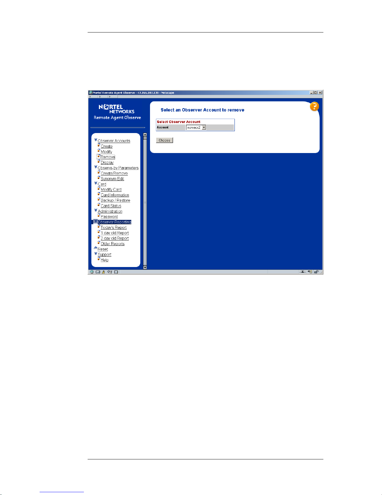
Nortel Proprietary
5.6 Removal of Observer Accounts
Accounts are removed by navigating the browser tree on the left side of the
Browser User Interface to the Observer Accounts > Remove page as shown in
Figure 20.
Figure 20 Observer Account Remove Page
The administrator chooses the account they wish to remove by choosing the
account via the drop-down list and then clicking the “choose” button.
This will move them on the delete page which is as shown below in Figure 21.
Planning, Installation and Administration Guide
58
Page 59

Nortel Proprietary
Figure 21 Observer Account Removal Page
If the administrator chooses the “Remove” option, they will be moved to the
observer account removal confirm page as shown in Figure 22.
Planning, Installation and Administration Guide
59
Page 60

Nortel Proprietary
Figure 22 Observer Account Removal Confirm Page
If the administrator chooses the “DeleteAccount” option, the observer account will
be removed permanently from the card.
Planning, Installation and Administration Guide
60
Page 61

Nortel Proprietary
5.7 Display of Accounts
Accounts are created by navigating the browser tree on the left side of the Browser
User Interface to the Observer Accounts > Display page as shown in Figure 23.
Figure 23 Observer Account Display Selection Page
The administrator chooses the account they wish to display by choosing the
account via the drop-down list and then clicking the “display” button. This will
move them on the display page which is as shown below in Figure 24.
Planning, Installation and Administration Guide
61
Page 62
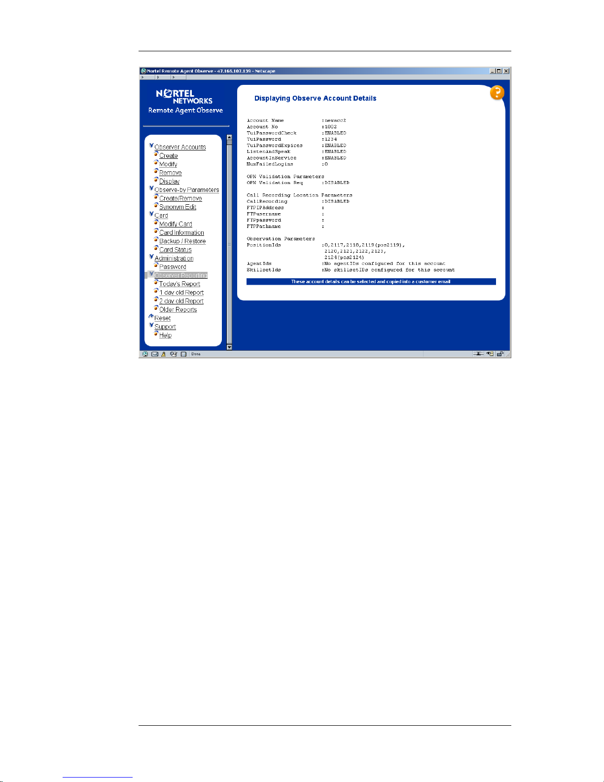
Nortel Proprietary
Figure 24 Observer Account Display Page
The display shows all the account parameters configured using the account
create/modify pages and additionally all the observe parameters that have been
assigned to the particular account. These observation parameters will be listed by
ID, but where a synonym (see the section “Observation Parameter Synonym
Assign” on page 67) has been assigned this will also be displayed.
Note: This account is displayed in text format to allow the account details to
be easily selected and copied into an email to send to the customer.
Planning, Installation and Administration Guide
62
Page 63

Nortel Proprietary
5.8 Observation Parameters Creation/Removal
Observation parameters are added/removed from observer accounts by navigating
the browser tree on the left side of the Browser User Interface to the Observe-by
Parameters > Create/Remove page as shown in Figure 25.
Figure 25 Observation Parameters Selection Page
The user chooses the account they wish to modify and the parameter-type they
wish to add/remove to that account using the drop-down lists and they then click
on the “select” button to get taken into the parameter add/remove page as shown
below in Figure 26.
Planning, Installation and Administration Guide
63
Page 64

Nortel Proprietary
Figure 26 Observation Parameters Modify/Removal Page
Population of All Available Parameters selection-box (SCCS server release 4.2
or later)
The contents of this selection box are populated by parsing the RSM stream from
the SCCS server. This will reflect all the data that has appeared in the RSM stream
for the last month. Data that has not appeared in the RSM stream in the last month
is deleted from the selection box of available parameters. This is to cater for
scenarios where for example agents may leave call-centres and it ensures that the
data presented to the administrator reflects the current status of the call-centre. If
the parameter subsequently re-appears in the RSM stream, the data will be added
once again to the selection box of available parameters.
Note: When the card is being initially configurable it may be advisable to leave the
card in the network for say 24 hours, before attempting to configure observer
accounts, as this will ensure that the contents of the selection box reflect as much
as possible of the entire SCCS observe-parameters contents.
When the parameter is being removed, it is only removed from the table of
available parameters and it is not removed from any accounts table it may
previously have been added to.
Planning, Installation and Administration Guide
64
Page 65

Nortel Proprietary
Population of All Available Parameters selection-box (Non-SCCS server and
pre-release 4.2 SCCS server)
The contents of the all available parameters selection box are filled from the
parameters that have previously been added to other accounts by the administrator
typing in entries into the “Type parameter” text box.
Explanation of Create/Remove Parameters Page
To add a parameter to account, the administrator will select the desired parameter
from the selection box of available parameters and they will then click the “Add”
button. The chosen parameter will be added to the list of parameters in the account
and will appear in the Account Parameters drop-down list.
To add all the available parameters to an account, the administrator will click the
“AddAll” button, under the available parameters selection box. All the parameters
present in the list of available parameters will be added to the account and will
appear in the Account Parameters drop-down list.
To add a new parameter (i.e. one not seen to date in the SCCS RSM stream and
thus not present in the selection box of available parameters), the administrator will
type the parameter in the “Type parameter” text box and will then click the “Insert”
button. The typed-in parameter will be added to the list of parameters in the
account and will appear in the Account Parameters drop-down list.
Similarly to remove a parameter from an account, the administrator will select the
desired parameter from the selection box of account parameters and they will then
click the “Remove” button. The chosen parameter will be removed from the list of
parameters in the account and will not appear in the Account Parameters dropdown list.
To remove all parameters from an account, the administrator will click the
“RemoveAll” button. All the parameters will be removed from the account and
will not appear in the Account Parameters drop-down list.
Note: If Nortel Remote Agent Observe is used in a large call centre with many
agents configured and in operation, it may take some time for the “Add All”
or “Remove All” functionality to complete. Allow over 1 minute for the BUI
page to refresh in these cases.
Planning, Installation and Administration Guide
65
Page 66

Nortel Proprietary
5.9 Symposium Name to ID Mapping
The multicast stream generated by SCCS, which is used by Nortel Remote Agent
Observe only contains IDs of parameters ie there is no parameter name information
present in the stream. To facilitate the use of names to be associated with
parameter IDs, Nortel Remote Agent Observe has the concept of synonyms, which
the administrator sets to be uniquely associated with individual parameter IDs. The
explanation of how to assign synonyms to parameters is described in 5.10:
Observation Parameters Synonym Assign.
The SCCS Classic Client contains reports which map names to IDs in the case of
the positionID and agentID parameters, so these can be used to assign relevant
“name based” synonyms. However, there is no method using the Classic Client of
mapping skillsetIDs (generated by the RSM steam and used by Remote Agent
Observe) to skillset names, which the end-user may be more familiar with.
However, by running the following commands at a MS-DOS command prompt on
the SCCS machine itself, the name to id mapping for skillsets can be discerned.
isql -Usysadmin -Ppassword -w350
1> use blue
2> go
1> select SkillsetID,Skillset from Skillset
2> go
SkillsetID Skillset
----------- ----------------------------- 1 Agent Queue To
2 Default ACD
3 Default NACD
10000 Default_Skillset
10007 Sales
10008 Support
10009 Finance
10010 IT
10011 vnvTestSkillset
10012 vnvTestSkillset_01
10013 vnvTestSkillset_02
10014 vnvTestSkillset_03
(12 rows affected)
1> quit
where the isql command takes as parameters:
U - the username and
P - login password
as used on the Symposium Classic Client
The SQL query returns the skillset names and IDs and these can be used in the
Observation Parameter Synonym Assign section below.
Planning, Installation and Administration Guide
66
Page 67

Nortel Proprietary
5.10Observation Parameters Synonym Assign
Synonyms are names associated with parameter IDs. They are set up by the
administrator to help identity parameters for the observer, so that when the
observer is accessing the card they can more readily identify the parameters they
wish to observe-by.
Synonyms are assigned/unassigned from parameters by navigating the browser tree
on the left side of the Browser User Interface to the Observe-by Parameters >
Synonym Edit page as shown in Figure 27.
Figure 27 BUI Synonym Parameter Selection Page
The administrator will choose the parameter type that they wish to assign
synonyms to and once they click the “edit” button, they will be guided into the
synonym assignment page as shown below in Figure 28.
Planning, Installation and Administration Guide
67
Page 68

Nortel Proprietary
Figure 28 BUI Synonym Assignment Page
The administrator will select the parameter they wish to assign from the drop-down
list of available parameters and they will type in the synonym they wish to assign
in the “Synonym To Assign” textbox and then press the “Assign” button. The
synonym will be assigned to the relevant parameter.
To unassign a synonym from a parameter, select the parameter to remove the
parameter from and click the “Unassign” button. The synonym will be unassigned
from the relevant parameter.
Planning, Installation and Administration Guide
68
Page 69

Nortel Proprietary
5.11Backup/Restore
Card configuration and observer accounts are backed-up and restored by
navigating the browser tree on the left side of the Browser User Interface to the
Card > Backup/Restore page as shown in Figure 29.
Note: the card must be disabled at the switch (using overlay 32 DISC command)
before performing any backups or restores.
Figure 29 BUI Backup/Restore Page
Backup
To back up the configuration or account data, type the full path to the backup file
in the appropriate text-box. When the “ConfigBackup” or “AccountBackup”
button is pressed, the Account File or the Configuration File will be FTPed as
appropriate to the remote FTP location.
Restore
To restore the configuration or account data, type the full path to the backup file in
the appropriate text-box. When the “ConfigRestore” or “AccountRestore” button
is pressed, the Account File or the Configuration File will be FTPed as appropriate
from the remote FTP location.
Planning, Installation and Administration Guide
69
Page 70

Nortel Proprietary
5.12Administration Password
The BUI password can be configured by navigating the browser tree on the left
side of the Browser User Interface to the Administration > Password page as
shown in Figure 30.
Figure 30 BUI Administrator Password Modify Page
The administrator can change their BUI password by entering their old password,
their new password, validation of their new password in the appropriate text boxes
and then clicking the “Change button”.
Planning, Installation and Administration Guide
70
Page 71

Nortel Proprietary
5.13Observer Reporting
The observation reports can be accessed by navigating the browser tree on the left
side of the Browser User Interface to the “Observer Reporting > Todays Report”,
“Observer Reporting > 1 Day old Report” or “Observer Reporting > 2 Day old
Report” page as shown in Figure 31.
Figure 31 BUI Observer Activity Logging Page
These reports show the channel, time of event, event-type, observer account name,
duration of event and details of the event recorded.
Type Description
Channel Card Channel the event occurred on
Time Time of Event
Event The type of event that occurred
Observer The observer account name that the event occurred on
Duration The length(in seconds) of the event (e.g. how long the observe
lasted)
Message This provides information on the event.
Table 12 Reporting Log-File Explanation
The day old and 2 day old reports contain an observation statistics section at the
end of the report file. This shows the totals of different types of observation
performed (i.e. agent ID observe, position ID observe, etc...). These statistics are
divided into two sections:
Planning, Installation and Administration Guide
71
Page 72

Nortel Proprietary
1. Statistics for the last 24 hour period
2. Overall statistics since the Nortel Remote Agent Observe card was installed.
The card has sufficient disk-space for the current days report and the previous 2
days reports to be stored on the card. Only these files may be viewed from the BUI
as described above. However, to store observer reports older than 2 days old, a
reporting FTP server must be configured to allow external storage to older report
files. If the administrator navigates the browser tree on the left side of the Browser
User Interface to “Observer Reporting > Older Reports”, they are presented with
the page shown in Figure 32 below. The page informs the administrator of the need
for a reporting FTP server.
Figure 32 Older Reports Message Display
Once the FTP server is configured, the previous day’s observer report file is
transferred every 24 hours at midnight from the card to the FTP server.
Note: These externally stored report files are not viewable from the BUI, but are in
text format and may be viewed from standard windows text viewers.
The observer report files have also been formatted specifically so that they are
readily exportable to other applications (e.g. spreadsheets), so that the
administrator can customise their own reports or group the data according to their
own particular needs.
Planning, Installation and Administration Guide
72
Page 73

Nortel Proprietary
5.14Card Reset
The card can be reset by navigating the browser tree on the left side of the Browser
User Interface to the Reset page as shown in Figure 33.
Figure 33 BUI Card Reset Page
The administrator can reset the card by clicking the “Yes” button on the Reset
Page.
The card will need to be reset in the following scenarios:
• During the install process when the keycode and Multicast settings are being
configured.
• If additional ports are configured using a keycode change and a switch
configuration level change.
Before the card is rebooted, the card will backup the current account and parameter
data. This ensures that after reboot the information is up to date.
The data backup task runs every five minutes on the Nortel Remote Agent Observe
Card. If the Card is rebooted through either pressing the faceplate reset button or
through locking latches, any new data generated since the last backup will be lost.
For this reason, it is strongly recommended that the card only be rebooted through
the Browser User Interface Card Reset page or through issuing the command
mirosReboot at the maintenance port command line interface.
Planning, Installation and Administration Guide
73
Page 74

Nortel Proprietary
-> mirosReboot
Result:
Rebooting Pack ...
value = 0 = 0x0
This command performs a backup of all the data before rebooting the Card.
Planning, Installation and Administration Guide
74
Page 75

Nortel Proprietary
6 Using the Telephony User Interface
6.1 Accessing the Telephony User Interface
The Nortel Remote Agent Observe Administrator and all Observers can access the
Telephony User Interface (TUI) by dialing the DN configured as the MADN as
described in “Switch configuration for Nortel Remote Agent Observe Sessions” on
page 27.
6.2 Quick Reference Card
There are two Quick Reference Cards (QRC) available. These reference cards
summarise the functionality available via the TUI.
• The SCCS QRC is designed for use in call centre which use SCCS 4.2 and
later.
• The non-SCCS QRC is designed for use in call centre which use pre 4.2
SCCS and for non-SCCS call centers.
The Quick Reference Cards will be available on Nortel Technical Documentation
(Helmsman) page at:
http://www130.Nortelnetworks.com/cgi-bin/eserv/cs/main.jsp?cscat=documentation.
NOTE: To access the document:
1. From the Documentation home page select “Symposium” from the “By
Product Family” list
2. Then find Nortel Remote Agent Observe from the available list of
products.
Planning, Installation and Administration Guide
75
Page 76

Nortel Proprietary
6.3 TUI Authentication
To Log into the Nortel Remote Agent Observe TUI, the Administrator or Observer
must first be authenticated.
Administrator TUI Login
The administrator account is automatically created with a default user ID and
password. To access the TUI for the first time, the administrator must log in using
this default user ID and password combination supplied. The administrator TUI
password may then be changed (see Administrator TUI Password Change, section
6.4: “Administrator TUI Menu”).
Observer TUI Login
When Creating Observer Accounts on the Browser User Interface (BUI) (see
section 5.4: “Creation of Observer Accounts”), the administrator assigns the
observer a TUI password. This may then be supplied to the observer with all other
account information. The observer must then use this user ID/ password
combination to log into the TUI.
TUI Login Security Checks
There are three different security checks in place to deal with repeated loginfailures on the TUI. They are:
1. Three invalid passwords entered for the same valid User ID on a single call.
If a caller enters three invalid passwords for a valid User ID, then a
message indicating login failure is played and the call is terminated by the
Nortel Remote Agent Observe TUI.
If the above security breach occurs for a specific user ID on three
successive occasions, then the account is disabled and may only be reenabled by the administrator.
2. Greater than three valid user IDs used during a single login attempt.
If a caller fails to login correctly after using more than 3 different valid user
IDs, then a message indicating login failure is played and the call is
terminated.
3. Greater than nine failed login attempts on a single call.
If a caller fails to login after 9 User ID/password combination attempts then
a message indicating login failure is played and the call is terminated.
Planning, Installation and Administration Guide
76
Page 77

Nortel Proprietary
In the case of any of the above security breaches, the login failure is reported in
that days reporting file.
It is also possible to configure an alarm, which will call predefined number(s) and
alert the administrator if any of the above security breaches occur.
Planning, Installation and Administration Guide
77
Page 78

Nortel Proprietary
6.4 Administrator TUI Menu
The Administrator may use the TUI to do the following:
• Change their TUI password
• Locally record custom TUI prompts (see Local TUI Prompt Recording, section
6.6 “TUI Language Administration”).
Note: The default administrator User ID is 1000 and the default administrator
password is 9999.
Administrator TUI Password Change
To Change the TUI password, the Administrator must run through the following
procedure.
1 Dial into the TUI and log in using the current user ID/ password combination.
2 Press ‘1’ to change TUI password.
3 Follow instructions to enter old TUI password.
4 Enter new TUI password.
5 Re-enter new TUI password for authentication purposes.
When completed, a message is played to inform the administrator that the TUI
password has been changed. If the administrator wishes to abort the TUI password
change at any stage then they should press ‘*’.
Note: The administrator must hang up before the new TUI password will take
effect.
Planning, Installation and Administration Guide
78
Page 79

Nortel Proprietary
6.5 Observer TUI Menu
The Observer will be the most frequent user of the Telephony User Interface. From
the TUI they can choose to observe by any of the following parameters, depending
on their permissions and on the type of call centre Nortel Remote Agent Observe is
operating in.
• Agent ID
• Position ID
• Skillset
• DNIS
• Application ID
• CDN
Note: If none of the above observation parameters are entered into an
observers account, the observer will have no observation permissions.
In this case, if the observer logs into the TUI, a message will be played
notifying the observer that they have no observation permissions before the
call is automatically terminated.
Agent ID Observation
To observe by agent ID, follow the procedure below (see Figure 37 for flow
diagram).
1. Log into the TUI using the observer user ID/ password combination.
2. Press ‘1’ to observe by agent ID.
Note: The observer’s account must have agent IDs entered into it by
the administrator for the Agent ID Observation option to be available
from the TUI.
3. The observer is then presented with the following options:
a. Press ‘1’ to enter an agent ID. The observer is then prompted to
enter the agent ID they wish to observe. If they have permission to
observe this agent, then observation shall start immediately (see
Figure 38).
b. Press ‘2’ to observe the first active agent ID. Pressing this key will
result in observation commencing on the first (numerically) active
agent ID configured for the observer. If no agent, in the observer’s
list of agent IDs is active, the observer is notified that no active
agents are currently present (see Figure 38).
4. When completed, the observer presses ‘*’ to return to the main menu or
hangs up.
Planning, Installation and Administration Guide
79
Page 80

Nortel Proprietary
Position ID Observation
To observe by position ID, follow the procedure below (see Figure 37).
1. Log into the TUI using the observer user ID/ password combination.
2. Press ‘2’ to observe by position ID.
Note: The observer’s account must have position IDs entered into it by
the administrator for the Position ID Observation option to be
available from the TUI.
3. The observer is then presented with the following options:
a. Press ‘1’ to enter a Position ID. The observer is then prompted to
enter the Position ID they wish to observe. If they have permission
to observe this position ID, then observation shall start immediately
(see Figure 38)
b. Press ‘2’ to observe the first active position ID. Pressing this key
will result in observation commencing on the first (numerically)
active position ID configured for the observer. If no agent, in the
observer’s list of position IDs is active, the observer is notified that
no active position is currently present (see Figure 38)
4. When completed, the observer presses ‘*’ to return to the main menu or
hangs up.
Skillset Observation
To observe by skillset, follow the procedure below (see Figure 39).
1. Log into the TUI using the observer user ID/ password combination.
2. Press ‘3’ to observe by skillset.
Note: The observer’s account must have skillset IDs entered into it by
the administrator for the Skillset Observation option to be available
from the TUI.
3. The observer is then presented with the following options:
a. Press ‘1’ to enter a skillset ID. The observer is then prompted to
enter the skillset ID they wish to observe. If they have permission to
observe this skillset ID, then observation shall start on the next call
to arrive for that skillset (see Figure 40).
b. Press ‘2’ to choose from the list of skillset IDs they have permission
to observe. They are presented with the first skillset ID in the list
followed by the following options:
i. Press ‘2’ to Select the Current Skillset ID. If chosen,
observation will start on the next call to arrive for that
skillset (see Figure 40).
Planning, Installation and Administration Guide
80
Page 81

Nortel Proprietary
ii. Press ‘4’ to go to the previous entry in the list. If pressed, the
previous skillset ID is presented to the observer, where the
skillset ID may then be chosen.
iii. Press ‘6’ to go to the next entry in the list. If pressed, the
next skillset ID is presented to the observer, where the
skillset ID may then be chosen.
To return to the main skillset observation menu, press ‘*’
4. When completed, the observer presses ‘*’ to return to the main menu or
hangs up.
DNIS Observation
To observe by DNIS, follow the procedure below (see Figure 39).
1. Log into the TUI using the observer user ID/ password combination.
2. Press ‘4’ to observe by DNIS.
Note: The observer’s account must have DNIS’ entered into it by the
administrator for the DNIS Observation option to be available from
the TUI.
3. The observer is then presented with the following options:
a. Press ‘1’ to enter a DNIS. The observer is then prompted to enter
the DNIS they wish to observe. If they have permission to observe
this DNIS, then observation shall start on the next call to arrive on
that DNIS (see Figure 40).
b. Press ‘2’ to choose from the list of DNIS’ they have permission to
observe. They are presented with the first DNIS in the list followed
by the following options:
i. Press ‘2’ to Select the Current DNIS. If chosen, observation
will start on the next call to arrive on that DNIS (see Figure
40).
ii. Press ‘4’ to go to the previous entry in the list. If pressed, the
previous DNIS is presented to the observer, where the DNIS
may then be chosen.
iii. Press ‘6’ to go to the next entry in the list. If pressed, the
next DNIS is presented to the observer, where the DNIS may
then be chosen.
To return to the main DNIS observation menu, press ‘*’
4. When completed, the observer presses ‘*’ to return to the main menu or
hangs up.
Planning, Installation and Administration Guide
81
Page 82

Nortel Proprietary
Application ID Observation
To observe by application ID, follow the procedure below (see Figure 39).
1. Log into the TUI using the observer user ID/ password combination.
2. Press ‘5’ to observe by application ID.
Note: The observer’s account must have application IDs entered into it
by the administrator for the application ID Observation option to be
available from the TUI.
3. The observer is then presented with the following options:
a. Press ‘1’ to enter an application ID. The observer is then prompted
to enter the Application ID they wish to observe. If they have
permission to observe this application ID, then observation shall
start on the next call to arrive for that application ID (see Figure 40).
b. Press ‘2’ to choose from the list of application IDs they have
permission to observe. They are presented with the first application
ID in the list followed by the following options:
i. Press ‘2’ to select the Current application ID. If chosen,
observation will start on the next call to arrive for that
application ID (see Figure 40).
ii. Press ‘4’ to go to the previous entry in the list. If pressed, the
previous application ID is presented to the observer, where
the application ID may then be chosen.
iii. Press ‘6’ to go to the next entry in the list. If pressed, the
next application ID is presented to the observer, where the
application ID may then be chosen.
To return to the main application ID observation menu, press ‘*’
4. When completed, the observer presses ‘*’ to return to the main menu or
hangs up.
CDN Observation
To observe by CDN, follow the procedure below (see Figure 39).
1. Log into the TUI using the observer user ID/ password combination.
2. Press ‘6’ to observe by CDN.
Note: The observer’s account must have CDNs entered into it by the
administrator for the CDN Observation option to be available from the
TUI.
3. The observer is then presented with the following options:
Planning, Installation and Administration Guide
82
Page 83

Nortel Proprietary
a. Press ‘1’ to enter a CDN. The observer is then prompted to enter the
CDN they wish to observe. If they have permission to observe this
CDN, then observation shall start on the next call to arrive on that
CDN (see Figure 40).
b. Press ‘2’ to choose from the list of CDNs they have permission to
observe. They are presented with the first CDN in the list followed
by the following options:
i. Press ‘2’ to Select the Current CDN. If chosen, observation
will start on the next call to arrive on that CDN (see Figure
40).
ii. Press ‘4’ to go to the previous entry in the list. If pressed, the
previous CDN is presented to the observer, where the CDN
may then be chosen.
iii. Press ‘6’ to go to the next entry in the list. If pressed, the
next CDN is presented to the observer, where the CDN may
then be chosen.
To return to the main CDN observation menu, press ‘*’
4. When completed, the observer presses ‘*’ to return to the main menu or
hangs up.
Non SCCS Call Centre Observation
When using Nortel Remote Agent Observe in a non SCCS call centre, the observer
only has the ability to observe by position ID.
To observe by position ID on a non SCCS call centre, follow the procedure below
(see Figure 41).
1. Log into the TUI using the observer user ID/ password combination.
2. The observer is then presented with the following options:
a. Press ‘1’ to enter a Position ID. The observer is then prompted to
enter the Position ID they wish to observe. If they have permission
to observe this position ID, then observation shall start (see Figure
42).
b. Press ‘2’ to observe the first active agent ID. Nortel Remote Agent
Observe goes through the list of position IDs the observer has
permission to observe and checks if any of these positions are valid.
If it finds a valid agent it starts observation on that position ID (see
Figure 42), otherwise the observer is notified that no valid position
IDs are currently available.
3. When completed, the observer presses ‘*’ to return to the main menu or
hangs up.
Planning, Installation and Administration Guide
83
Page 84

Nortel Proprietary
Note: The observer’s account must have position IDs entered into it by the
administrator for the Non-SCCS Observation option to be available from the
TUI.
Playing Currently Observed ID
If observing on a call, by pressing ‘5’, the observer will hear the ID of the
parameter they are currently observing on.
Examples of what is played are:
a. Agent ID – “Agent ID XXXX”.
b. Position ID – “Position ID XXXX”.
c. Skillset – “Skillset ID XXXX”.
d. DNIS – “DNIS XXXX”.
e. Application ID – “Application ID XXXX”.
f. CDN – “CDN XXXX”.
“Remain with Agent”
The option exists when observing by skillset, DNIS, application ID or CDN,
whereby if the observer is observing an agent on a call, they may choose to remain
observing calls routed to this agent at the end of the call rather than waiting for the
next call to arrive for a skillset/DNIS/application ID/CDN.
To choose this option, press ‘7’ while observing the agent call. When the call ends,
the observer will be told that rather than wait for a call on skillset/DNIS/application
ID/CDN, they are waiting for a call on the Agent ID.
This will be of benefit if there is something of concern to the observer about the
way this specific agent is handling calls.
When finished observing on this specific agent, the observer may press ‘*’ to
return to the skillset/DNIS/application ID/CDN selection menu.
Listen and Speak Mode.
If observing an agent call, the option exists to allow the observer to enter into and
speak on the call.
To enter and speak on the call, press ‘2’ followed by ‘1’ while observing a call.
The observer will then be notified that they are entering the agent call, after which
they will be able to speak on the call.
To leave the call, press ‘3’. The observer will be told that they are exiting the agent
call and they will continue to observe the call without the ability to speak.
If the observed call ends while in listen and speak mode, the mode is automatically
ended.
Planning, Installation and Administration Guide
84
Page 85

Nortel Proprietary
Note: The administrator must first activate Listen and Speak permissions in
the Observer account before these options become available while observing a
call.
Observation Status Message Interval
When observing by any of the available observation parameters, while waiting for
the next call a status message is played to the observer at regular intervals.
Examples of the observation status message are:
a. Agent ID – “Waiting for call on agent ID: xxxx”
b. Position ID – “Waiting for call on position ID: xxxx”
c. Skillset – “Waiting for call on skillset ID: xxxxx”
d. DNIS – “Waiting for call on DNIS: xxxx”
e. Application ID – “Waiting for call on application ID: xxxx”
f. CDN – “Waiting for call on CDN: xxxx”
The default observation status message interval is 30 seconds. However this may
be configurable to any length above the default interval.
To modify the interval length, from the shell type:
tuiSetObservationStatusInterval(60) <CR>
Where the value passed to the command is the interval length in seconds (the
above example sets the interval to 60 seconds).
To get the current observation status message interval, type the following from the
shell, which will display the interval:
tuiGetObservationStatusInterval <CR>.
Planning, Installation and Administration Guide
85
Page 86

Nortel Proprietary
6.6 TUI Language Administration
The Nortel Remote Agent Card is shipped with a set of default TUI language
prompts. These default prompts in are English spoken by an American speaker.
Nortel also provides a set of TUI prompts in "UK" English and in French. These
prompt sets can be downloaded from the Meridian Patch Library (MPL) website.
Other languages are supported on the card via two facilities which allow customers
or distributors to record the TUI prompt set in a local language.
• The prompt set may be pre-recorded externally and loaded onto the Nortel
Remote Agent Observe card (described later in this section)
• The Administrator may record the prompt set in the required language by
dialing into the TUI (described later in this section)
Voice Prompt Level Regulatory Requirements
Please note that the energy levels of the TUI prompts are subject to regulatory
requirements1. Nortel recommends that the power level of the custom language
prompts reach -12dBm max when averaged over a 3 second interval. It is the
responsibility of the customer to ensure that any custom language prompts that
they record and install meet these regulatory requirements. The language prompts
(“American” English, “UK” English and French) supplied by Nortel are within the
specified regulatory limits.
Installing Nortel Provided Custom Language Prompts
Custom Language TUI prompts are provided by Nortel in a number of languages.
These prompts are provided in an MCF format and thus no conversion process is
required once these prompts are placed on the card. These prompt files all have a
.mcf extension.
Note: Custom Language Prompt installation will over-write any prompts
previously stored in the custom language directory on the card. Before
installing the provided custom language TUI prompts, ensure that a backup of
any existing custom prompts are kept at an external location. See Backup of
Custom TUI Prompts on page 89.
To install the prompts follow the instructions below:
1. Disable the Remote Agent Observe card from overlay 32 of the switch.
2. FTP onto the card and copy the custom prompts into the /C:/TUI/CUSTOM
directory. See “Multiple File Transfer using FTP” at the end of section 6.6.
3. Enable the Remote Agent Observe card from overlay 32 of the switch.
1
“Telecommunication Apparatus Compliance Specification” – “Specification for Terminal
Equipment, Terminal Systems, Network Protection Devices, Connection Arrangements and Hearing
Aids Compatibility”: CS-03, Issue 8, Release 15 June 1996.
Planning, Installation and Administration Guide
86
Page 87

Nortel Proprietary
The custom TUI prompts are enabled via the Browser User Interface (BUI). See
language configuration in the “Configuring the Card” section, page 48 for TUI
language selection.
Installing Externally Recorded TUI Prompts
Custom TUI Prompts may be professionally recorded at an external studio and
installed on the card.
Notes:
1. The professionally recorded prompts MUST be G.711 u-law WAV file
Format.
2. The filenames MUST follow the filename format shown on the TUI prompt
list (see section 12.3:”TUI Prompt List”).
3. The .wav file extension MUST also be in lower case.
4. Make an external copy of the prompts before commencing installation. The
Nortel Remote Agent Observe Card has limited disk space, so when the
conversion process from G.711 u-law to MCF format has taken place, the
G.711 u-law files will be deleted from the card.
5. TUI Prompt installation will over-write any prompts previously stored in
the custom language directory on the card. Before installing the externally
recorded custom TUI prompts, ensure that a backup of the prompts are kept
at an external location. See Backup of Custom TUI Prompts on page 89.
To install the prompts follow the instructions below.
1. Disable the Remote Agent Observe card from overly 32 of the switch.
2. FTP onto the card and copy the custom prompts into the /C:/TUI/WAV/
directory. See “Multiple File Transfer using FTP” at the end of section 6.6.
3. Log into the shell. The default username is “raoadmin” and the default
password is “raosecurity”.
4. From the shell type ll “/C:/TUI/WAV” <CR>
to ensure that all the pre-recorded prompts have been transferred correctly
onto the card.
5. From the shell type convertWavFiles <CR>.
This initiates the prompt file installation. To signify this, the following message
appears on the terminal:
“mirosConvertWavDir: Convert dir ‘/C:/TUI/WAV’ ”
6. If you wish to follow the progress of the conversion, from the shell, type:
wavConvDebugOn <CR>
Planning, Installation and Administration Guide
87
Page 88

Nortel Proprietary
Each file name will be displayed as its being converted. To turn off this extra
logging, from the shell, type: wavConvDebugOff <CR>.
7. The prompt conversion may take up to 20 minutes to complete, at which point
the following message will appear on the terminal:
“mirosConvertWavDir: dir conversion complete”
8. Once installation is complete, the /C:/TUI/CUSTOM directory will contain the
pre-recorded prompts in the correct format and the initial wav files will have
been erased from the card. To verify this, do the following:
a. From the shell, type ll “/C:/TUI/CUSTOM”.
The drive should contain the new prompts in .mcf file format.
b. From the shell, type ll “/C:/TUI/WAV”.
The directory where the professionally recorded wav files were
originally stored should now be empty.
9. Re-enable the card from overlay 32 of the switch.
The custom TUI prompts are enabled via the Browser User Interface (BUI). See
language configuration on page 48 for TUI language selection.
Local TUI Prompt Recording
The administrator has the ability to locally record a set of custom prompts using
the TUI.
Notes:
1. Any prompts locally recorded will over-write any prompts previously
stored in the custom language directory on the card. Before editing the custom
TUI prompts, ensure that a backup of the prompts are kept at an external
location. See Backup of Custom TUI Prompts on page 89.
2. The full list of custom TUI prompts must be recorded before Nortel Remote
Agent Observe will allow the use of the Custom TUI language.
The following procedure highlights the steps to edit the Custom TUI prompts.
1. Before editing the custom TUI prompts, have a copy of the TUI prompt list
at hand (see section 12.3:”TUI Prompt List”). This is required to have
knowledge of the prompt number associated with each prompt.
2. Log into the TUI using the Administrator user ID/ password combination.
3. Press ‘2’ to edit the custom TUI prompts.
4. A message is played to advise the administrator to enter the first prompt
they wish to edit. The administrator then enters the prompt number
associated with the prompt they desire to edit (see section 12.3:”TUI
Prompt List”).
Planning, Installation and Administration Guide
88
Page 89

Nortel Proprietary
5. The administrator is then provided with a list of options available to them.
They are:
a. Press ‘1’ to listen to the prompt in the default language (English).
b. Press ‘2’ to listen to the prompt in the custom language. If no
prompt exists in the custom language, a beep is heard.
c. Press ‘3’ to start recording the prompt in the custom language.
When pressed, the administrator will be advised on when to start
speaking and how to stop the recording.
d. Press ‘4’ to move to the previous prompt. If the administrator has
completed editing the prompt, he may press this to quickly scroll
backward to a previous prompt.
e. Press ‘5’ to move to the next prompt. If the administrator has
completed editing the prompt, he may press this to quickly scroll
forward to a previous prompt.
f. Press ‘6’ to play the current Prompt ID. This will play the prompt
number if at any stage the administrator wishes to know the number
of the prompt being edited.
After any of the options have been selected and the operation has been
completed, the list of options will then be replayed to the administrator
6. If the administrator at any stage wishes to end editing of the custom TUI
prompts, the ‘*’ key may be pressed and the administrator will return to the
main menu.
The custom TUI prompts are enabled via the Browser User Interface (BUI). See
language configuration in the “Configuring the Card” section, page 48, for TUI
language selection.
Note: After editing the custom TUI prompts, keep a backup of the files at an
external location. See Backup of Custom TUI Prompts on page 89.
Backup of Custom TUI Prompts
It is recommended that a backup of the current TUI Custom Language Prompts are
kept at an external location. To backup the prompts, do the following:
1. Disable the Card from overlay 32 on the Meridian Switch.
2. FTP onto the Nortel Remote Agent Observe card and transfer the files from the
/C:/TUI/CUSTOM directory to the external location. See “Multiple File
Transfer using FTP” at the end of section 6.6.
3. Re-enable the card from overlay 32 on the Meridian switch
Planning, Installation and Administration Guide
89
Page 90

Nortel Proprietary
Multiple File Transfer using FTP
To transfer multiple files using ftp, use the mput or mget commands instead of put
and get commands respectively. To speed up this process, first use the prompt
command which will turn off interactive mode. i.e. you will not be requested for
confirmation of each file transfer.
Note: By turning off interactive mode, the FTP transfer will automatically
overwrite any files of the same name in the target directory.
Figure 34 below shows an example of a multiple file transfer. In this case the
transfer is of multiple .mcf files to the “/C:/TUI/CUSTOM” directory. <Card IP
Address> is the IP Address of the Nortel Remote Agent Observe card.
ftp <Card IP Address>
Connected to <Card IP Address>.
220 VxWorks FTP server (VxWorks 5.4) ready.
Name (<Card IP Address>.:hansha): raoadmin
331 Password required
Password:
230 User logged in
ftp> bin
200 Type set to I, binary mode
ftp> cd "/C:/TUI/CUSTOM"
250 Changed directory to "<directory path>""
ftp> prompt
Interactive mode off.
ftp> mput *.mcf
200 Port set okay
150 Opening BINARY mode data connection
226 Transfer complete
local: 10.mcf remote: 10.mcf
2520 bytes sent in 0.038 seconds (65.33 Kbytes/s)
200 Port set okay
150 Opening BINARY mode data connection
226 Transfer complete
local: 11.mcf remote: 11.mcf
2160 bytes sent in 0.032 seconds (65.00 Kbytes/s)
...
...
...
...
200 Port set okay
150 Opening BINARY mode data connection
226 Transfer complete
local: ffffffff.mcf remote: ffffffff.mcf
2880 bytes sent in 0.022 seconds (125.37 Kbytes/s)
ftp> bye
221 Bye...see you later
Figure 34 Example of multiple file transfer using FTP
Planning, Installation and Administration Guide
90
Page 91

Nortel Proprietary
6.7 Telephony User Interface Menu Flows
The Following Figures show a sample of the menu flows of the Nortel Remote
Agent Observe TUI.
Position ID Observe and Agent ID Observe have very similar menu flows.
Similarly, skillset, DNIS, application and CDN Observations also have similar
menu flows.
The Menus shown here are:
1. TUI Login
2. SCCS select Menu
3. Agent ID Observe (Position ID Observe uses similar structure)
4. Skillset Observe (DNIS, CDN & Application ID Observe use similar
structure)
5. Non SCCS select Menu
6. Non SCCS Observe.
Planning, Installation and Administration Guide
91
Page 92

Nortel Proprietary
Figure 35 TUI Login Menu
Planning, Installation and Administration Guide
92
User
Dials In
“Welcome”
“User ID?”
Check Valid
entries
Database of
Observer IDs
and
passwords
“Login Failure,
Goodbye”
> Max No
Retries
Valid
Invalid
COLLECT DIGITS UNTIL # or TIMEOUT or
MAX LENGTH OF ID
DISC
“Invalid
User ID or password
Please try again?”
“Password?”
Yes
SCCS Select
Menu
COLLECT DIGITS UNTIL # or TIMEOUT or
MAX LENGTH OF PASSWORD
> Login Fail
Threshold
DEACTIVATE
ACCOUNT
Yes
No
No
SCCS Call
Centre?
Non-SCCS
Select Menu
Yes
No
Page 93

Nortel Proprietary
Figure 36 SCCS Main Menu
Planning, Installation and Administration Guide
93
Depending on functionality the following
announcements will be played
“To observe by agentID, press 1”
“To observe by positionID, press 2”
“To observe by skillset, press 3”
“To observe by DNIS, press 4”
“To observe by Application, press 5”
“To observe by CDN, press 6”
COLLECT DIGITS TO TIMEOUT
Case 1 Case 2 INVALID
“Invalid Entry”
SCCS
Main Menu
PositionID
Select
Menu
AgentID
Select
Menu
Case 3 Case 5 Case 6
Skillset
Select
Menu
ApplicationID
Select
Menu
CDN
Select
Menu
DNIS
Select
Menu
Case 4
Page 94

Nortel Proprietary
Figure 37 Agent ID Select Menu (similar structure - Position ID Select Menu)
Planning, Installation and Administration Guide
94
Call Menu
Agent ID Observe
Menu
Agent ID = first agent in
Account list active on a call.
Active Agent ID
Found?
“No Active Agent ID at
this time”
“Enter agentID followd by #
COLLECT DIGITS TO * or #
or TIMEOUT
Valid Agent?
No
AgentID Select
Menu
Yes
“To enter an agent ID, press 1”
“To start observing the first active agent, press 2”
“To exit, press *”
COLLECT DIGIT or TIMEOUT
INVALID
Case *Case 1
“Invalid Entry, please
try again”
Case 2
Logged in
Agent?
AgentID Observe
Call Men
Yes
“Agent is logged
out, please try
again”
“Invalid Agent
ID. Please try
again”
* or
TIMEOUT
?
No
SCCS Select
Menu
Yes
No
No
Yes
Page 95

Nortel Proprietary
Figure 38 Agent ID Observe Menu (similar structure - Position ID Observe Menu)
Planning, Installation and Administration Guide
95
Invalid
Case *
Play beep
Invoke M1 Agent Observe, Start
Recording
“Starting Observe on AgentID - XX”
Agent ID
Select
Menu
Digit
inputte
Invalid Case *
Stop M1 Remote
Observe
Stop Recording
Agent ID
Select
Menu
Activit
y
timeout
Call
activ
Stop M1 Remote
Observe
Stop Recording
Digit
inputte
Call
activ
Play beep
“Call Terminated”
Call
activ
“Waiting for call
on Agent ID: XX”
Agent ID
Observe
Call Menu
Page 96

Nortel Proprietary
Figure 39 Skillset Select Menu (similar structure - Application, CDN, DNIS Select Menus)
Planning, Installation and Administration Guide
96
Select
“Enter s killsetID and press #”
COLLECT DIGITS TO * or #
or TIMEOUT
Valid Skillset?
No
SkillsetID Observe
Menu
SkillsetID
Select Menu
Case 2
Yes
Case *
“To enter a Skillset, press 1”
“To choose from a list of your skillsets, press 2”
“To exit, press *”
COLLECT DIGIT or TIMEOUT
INVALID
Case *Case 1
“For next ID, press 6”
“For prev ID, press 4”
“To select ,press 2”
“To exit press *”
“Invalid Entry, please
try again”
Case 2
Announce Current ID.
In response to 4,6 announce
prev ,next ID until 2 or * selected
SkillsetID
Menu
SkillsetID Observe
Menu
“Invalid
Skillset ID, please
try again”
* or
TIMEOUT
?
No
SCCS S elect
Menu
Yes
CurrentID = 1st in list of
Valid IDs
Page 97

Nortel Proprietary
Figure 40 Skillset Observe Menu ( similar structure -Application, CDN and DNIS Observe)
Planning, Installation and Administration Guide
97
Invoke M1 Agent
Observe, Start
Recording.
No
Yes
Invalid
Case *
SkillsetID
Select
Menu
Digit
inputte
Yes
No
Invalid Case *
Stop M1 Remote
Observe
Stop Recording
SkillsetID
Select
Menu
Yes
Activi
ty
timeo
ut
No
Call
activ
Stop M1 Remote
Observe
Stop Recording
Digit
inputte
Call
activ
Yes
No
Play beep
Play beep
Yes
“Call Terminated”
“Waiting for call
on Skillset ID XX”
SkillsetID
Observe
Menu
Case 7
Observe this
agent until * is
pressed
No
Page 98

Nortel Proprietary
Figure 41 Non SCCS and pre Release 4.2 SCCS Main Menu
Planning, Installation and Administration Guide
98
“Enter PositionID and press #”
COLLECT DIGITS TO * or #
or TIMEOUT
Valid position ID?
No
Non-SCCS Observe
Menu
Non-SCCS
Select Menu
Yes
“To enter a position ID, press 1”
“To start observing the first valid position ID, press 2”
“To disconnect, press *”
COLLECT DIGIT or TIMEOUT
INVALID
Case *Case 1
“Invalid Entry, please
try again
Case 2
Non-SCCS Observe
Menu
“Invalid
Position ID, please
try again”
* or
TIMEOUT
No
DISC.
Yes
Position ID = first valid
position ID in account list.
Valid Position ID
Found ?
Yes
“No Active Position ID at
this time”
No
Page 99

Nortel Proprietary
Figure 42 Non SCCS and pre Release 4.2 SCCS Observe Menu
Planning, Installation and Administration Guide
99
Invoke M1 Agent
Observe.
Digit
inputted
Invalid Case *
Stop M1 Agent
Observe
Non-SCCS
Select
Menu
Play beep
Non-SCCS
Observe
Menu
Page 100

Nortel Proprietary
7 Call Recording
7.1 Introduction
Nortel Remote Agent Observe has a call recording capability available when used
as part of a SCCS call centre (running SCCS v4.2 or greater).
The call recording facility is configurable on a per-observer basis, so each
individual observer can be set up to record their calls to different FTP directories or
even different FTP servers, if so desired by the administrator.
For each observer for whom call recording is configured, all observed calls will be
recorded on an individual basis, thus providing the observer with a complete
distinguishable record of all that they listened to. For example, if an observer
decides to observe by agent ID, each call which is observed for that specific agent
during this period will be recorded to a separate call recording file on the FTP
server.
Only observed calls will be recorded.
7.2 Call Recording Configuration and Operation
Call recording is enabled on a per observer basis. If enabled calls being observed
are automatically recorded and stored at an external location.
To enable call recording, the FTP details required to transfer the recording to an
external server are entered by the administrator when creating or modifying the
observer’s account from the Browser User Interface (BUI). For more information
on this see section 5.4: “Creation of Observer Accounts”.
If call recording is enabled for a specific observer, when the observer dials into the
TUI and starts an observation (see section 6.5: “Observer TUI Menu” for more
information), recording also begins on that call. The recordings are stored in local
buffer files and are transferred to the external FTP server every twenty seconds.
When the call is completed and observation stops, recording also ends.
7.3 Call Recording File Format
The call recording file is stored on the external FTP server as a SUN Audio file
(with .au file extension). This format is compatible with Windows Media Player.
The filename allows the observer to distinguish between various recorded calls.
It contains the observers User ID, the date of the observation and the time of the
observation. Figure 43 and Figure 44 below show the make-up of the call recording
filename.
Nortel Remote Agent Observe supports both American and European date formats
(see Date Format, section 5.3: “Configuring the Card”). Depending on the date
format the filename will be different.
Figure 43 and Figure 44 below show the call recording filename for a call recorded
by Observer 1015 on July 1
st
, 2004.
Planning, Installation and Administration Guide
100
 Loading...