

Page 1

SL-1
NT5K02 and NT8D03 Analog Line Cards
Description
Publication number: 553-3001-161
Document release: 3.1
Document status: Standard
Date: March 1, 1992
© 1990 Northern Telecom
All rights reserved.
NT5K02 and NT8D03 Analog Line Cards 553-3001-161
Page 2

ii
Revision history
January 29, 1990
Standard, release 1.0.
July 31, 1990
Standard, release 2.0.
April 1, 1991
Standard, release 2.1
December 1,1991
Standard, release 3.0. Reissued to include technical content updates.
March 1, 1992
Standard, release 3.1.
NT5K02 and NT8D03 Analog Line Cards 553-3001-161
Page 3

Contents
iii
About this document 1
References 1
Description 3
NT8D03 Analog Line Card (µ-Law) 3
Physical description 4
Functional description 4
NT5K02 Flexible Analog Line Card (A-Law) 5
Application 5
Physical description 6
Functional description 8
Technical summary 9
NT8D03 Analog Line Card 9
Analog line interface 9
Input impedance 9
Insertion loss 9
Frequency response 9
Message channel noise 10
Power requirements 11
Foreign and surge voltage protection 11
Overload level 11
Backplane pin layout 12
NT5K02 Flexible Analog Line Card 13
Analog line interface 13
Input impedance 13
Insertion loss 14
Frequency response 14
Idle channel noise 15
NT5K02 and NT8D03 Analog Line Cards 553-3001-161
Page 4

iv Contents
Ringer limitations 15
Ground button detection 16
Power requirements 16
NT5K02 and NT8D03 Analog Line Cards 553-3001-161
Page 5

About this document
This document outlines the characteristics of the NT5K02 and NT8D03
Analog Line Cards. The information is intended to be used as a guide when
connecting customer-provided apparatus to the line cards.
References
See the Meridian 1 planning and engineering guide for
— Master index (553-3001-000)
— System overview (553-3001-100)
— System engineering (553-3001-151)
— Spares planning (553-3001-153)
— Equipment identification (553-3001-154)
See the Meridian 1 installation and maintenance guide for
1
— System installation procedures (553-3001-210)
Note: System installation procedures contains the procedures for the
analog line card cross-connections.
— Circuit card installation and testing (553-3001-211)
— Fault clearing (553-3001-510)
— Hardware replacement (553-3001-520)
NT5K02 and NT8D03 Analog Line Cards 553-3001-161
Page 6

2 About this document
See the X11 software guide for an overview of software architecture,
procedures for software installation and management, and a detailed
description of all X11 features and services. This information is contained
in two documents:
— X11 software management (553-3001-300)
— X11 features and services (553-3001-305)
See the X11 input/output guide (553-3001-400) for a description of all
administration programs, maintenance programs, and system messages.
NT5K02 and NT8D03 Analog Line Cards 553-3001-161
Page 7
Description
NT8D03 Analog Line Card (µ-Law)
The NT8D03 Analog Line Card provides talk battery and signaling for
regular 2-wire common battery 500-type (rotary dial) and 2500-type
(Digitone dial) telephones and key telephone equipment.
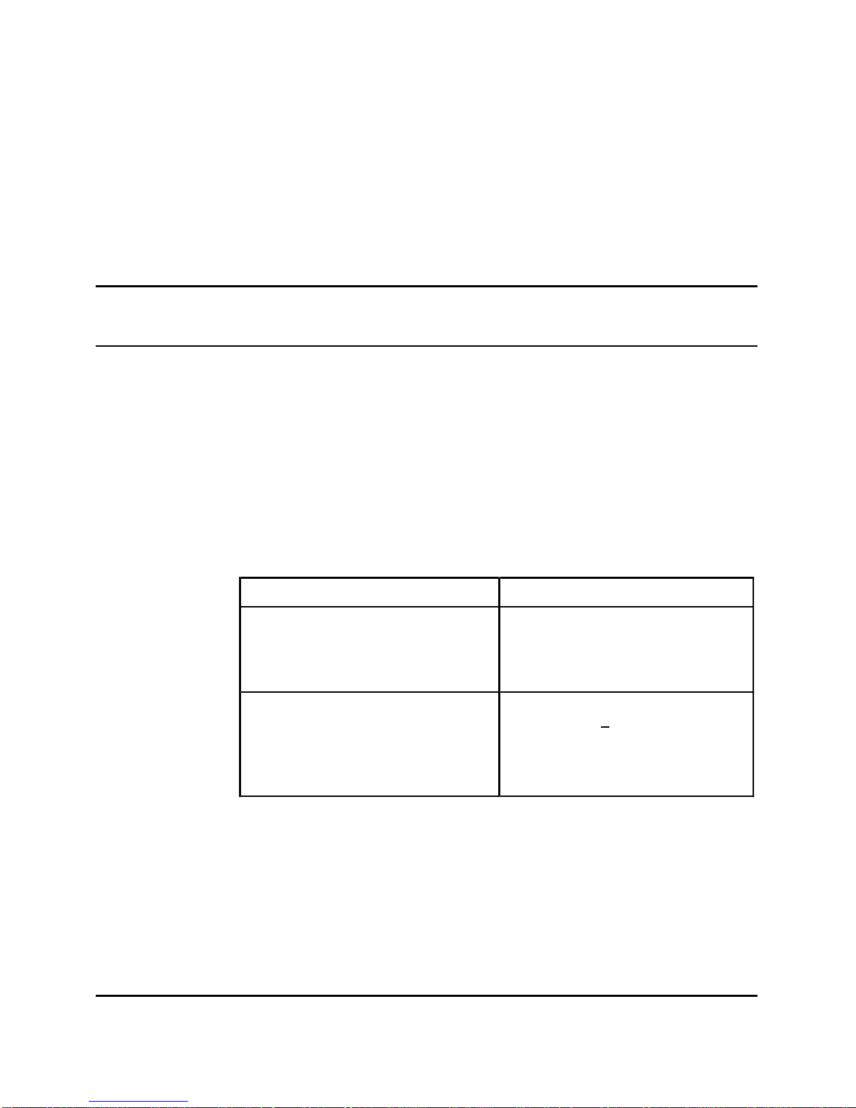
The analog line card interfaces to and is compatible with the equipment
listed in Table 1.
Table 1
NT8D03 Analog Line Card application and compatibility
Equipment Specifications
500-type rotary dial telephones:
dial speed
percent break
interdigit time
3
8.0 to 22.5 pps
58 to 70%
150 ms
2500-type Digitone telephones:
frequency accuracy
pulse duration
interdigit time
speed
NT5K02 and NT8D03 Analog Line Cards 553-3001-161
+ 1.5 %
40 ms
40 ms
12.5 digits/s
Page 8

4 Description
Physical description
Analog line cards are housed in:
— NT8D37 Intelligent Peripheral Equipment (IPE) Modules:
up to 16 cards
— NT8D11 Common/Peripheral Equipment (CE/PE) Modules:
up to 10 cards
The analog line card circuitry is mounted on a 31.75 by 25.40 cm (12.5 by
10 in.) printed circuit board.
The analog line card connects to the backplane through a 160-pin edge
connector. The backplane is cabled to the input/output (I/O) panel, which
connects to the main distribution frame (MDF), also called a cross-connect
terminal, through 25-pair cables. Telephones then connect to the card at the
MDF.
The faceplate of the analog line card is equipped with a red light emitting
diode (LED) which lights when the card is disabled. When the card is
installed, the LED remains lit for two to five seconds as a self-test runs. If
the self-test completes successfully, the LED flashes three times and
remains lit until the card is configured and enabled in software, then the
LED goes out. If the LED does not follow the pattern described or operates
in any other manner (such as continually flashing or remaining weakly lit),
the card should be replaced.
Functional description
The analog line card contains an 8051-family microprocessor that provides
the following functions:
— self-identification
— self-test
— control of card operation
— status report to the controller
— maintenance diagnostics
NT5K02 and NT8D03 Analog Line Cards 553-3001-161
Page 9

Description 5
The analog line card also provides:
— 600-ohm balanced terminating impedance
— analog-to-digital and digital-to-analog conversion of transmission and
reception signals for 16 audio telephone lines
— transmission and reception of scan and signaling device (SSD)
signaling messages over a DS30X signaling channel in A10 format
— on-hook and off-hook status detection
— 20-Hz ringing signal connection and automatic disconnection when the
telephone goes off-hook
— synchronization for connecting and disconnecting the ringing signal to
zero crossing of ringing voltage
— loopback of SSD messages and Pulse Code Modulation (PCM) signals
for diagnostic purposes
— correct initialization of all features, as configured in software, at
power-up
— direct reporting of digits dialed (500 telephones) by collecting dial
pulses
NT5K02 Flexible Analog Line Card (A-Law)
The NT5K02 Flexible Analog Line Card provides talk battery and
signalling for regular 2-wire common battery 500-type (rotary dial), 2500type (Digitone* dial) telephones and key telephone equipment. The
telephones may have either ground button recall switches, high voltage
message waiting lamps, or low voltage message waiting LEDs.
Application
The NT5K02 Flexible Analog Line Card is used as follows:
• NT5K02AA — High voltage message waiting analog line card
typically used in Australia.
• NT5K02DA — Ground button low voltage message waiting analog
line card typically used in France.
• NT5K02EA — Ground button low voltage message waiting analog line
card typically used in Germany.
NT5K02 and NT8D03 Analog Line Cards 553-3001-161
Page 10

6 Description
• NT5K02FA — Ground button low voltage message waiting analog line
card with 600 Ω termination (A/D -4dB, D/A -1dB).
• NT5K02GA — Same as NT5K02FA with different loss plan (A/D
-4dB, D/A -3dB)
• NT5K02HA — Ground button low voltage message waiting analog
line card typically used in Belgium.
• NT5K02JA — Low voltage message waiting analog line card typically
used in Denmark.
• NT5K02KA — Ground button low voltage message waiting analog
line card typically used in Netherlands.
• NT5K02LA — Analog line card typically used in New Zealand.
• NT5K02MA — Ground button low voltage message waiting analog
line card typically used in Norway.
• NT5K02NA — Ground button low voltage message waiting analog
line card typically used in Sweden.
• NT5K02PA — Ground button low voltage message waiting analog line
card typically used in Switzerland.
• NT5K02QA — Ground button low voltage analog line card typically
used in United Kingdom.
Physical description
Analog line cards are housed in:
— NT8D37 Intelligent Peripheral Equipment (IPE) Modules:
up to 16 cards
— NT8D11 Common/Peripheral Equipment (CE/PE) Modules:
up to 10 cards
The analog line card circuitry is mounted on a 31.75 by 25.40 cm (12.5 by
10 in.) printed circuit board.
The analog line card connects to the backplane through a 160-pin edge
connector. The backplane is cabled to the input/output (I/O) panel, which
connects to the main distribution frame (MDF), also called a cross-connect
terminal, through 25-pair cables. Telephones then connect to the card at the
MDF.
NT5K02 and NT8D03 Analog Line Cards 553-3001-161
Page 11

Description 7
The faceplate of the analog line card is equipped with a red light emitting
diode (LED) which lights when the card is disabled. When the card is
installed, the LED remains lit for two to five seconds as a self-test runs. If
the self-test completes successfully, the LED flashes three times and
remains lit until the card is configured and enabled in software, then the
LED goes out. If the LED does not follow the pattern described or operates
in any other manner (such as continually flashing or remaining weakly lit),
the card should be replaced.
NT5K02 and NT8D03 Analog Line Cards 553-3001-161
Page 12

8 Description
Functional description
The analog line card contains an 8051-family microprocessor that provides
the following functions:
— self-identification
— self-test
— control of card operation
— status report to the controller
— maintenance diagnostics
The analog line card also provides:
— 600-ohm balanced terminating impedance
— analog-to-digital and digital-to-analog conversion of transmission and
reception signals for 16 audio phone lines
— transmission and reception of scan and signaling device (SSD)
signaling messages over a DS30X signaling channel in A10 format
— on-hook and off-hook status detection
— 20-Hz ringing signal connection and automatic disconnection when the
station goes off-hook
— synchronization for connecting and disconnecting the ringing signal to
zero crossing of ringing voltage
— loopback of SSD messages and Pulse Code Modulation (PCM) signals
for diagnostic purposes
— correct initialization of all features at power-up
— direct reporting of digit dialed (500 sets) by collecting dial pulses
— ground button detection
NT5K02 and NT8D03 Analog Line Cards 553-3001-161
Page 13

Technical summary
NT8D03 Analog Line Card
Analog line interface
The NT8D03 Analog Line Card meets the EIA/TA464 standard for ONS
Type II line cards.
Input impedance
The impedance at tip and ring is 600 ohms with a return loss of
— 20 dB for 200-500 Hz
— 26 dB for 500-3400 Hz
Insertion loss
On a line to line connection, the total insertion loss at 1 kHz is 4 dB + 1 dB.
This is arranged as 3.5 dB loss for analog to PCM, and 0.5 dB loss for PCM
to analog.
9
Frequency response
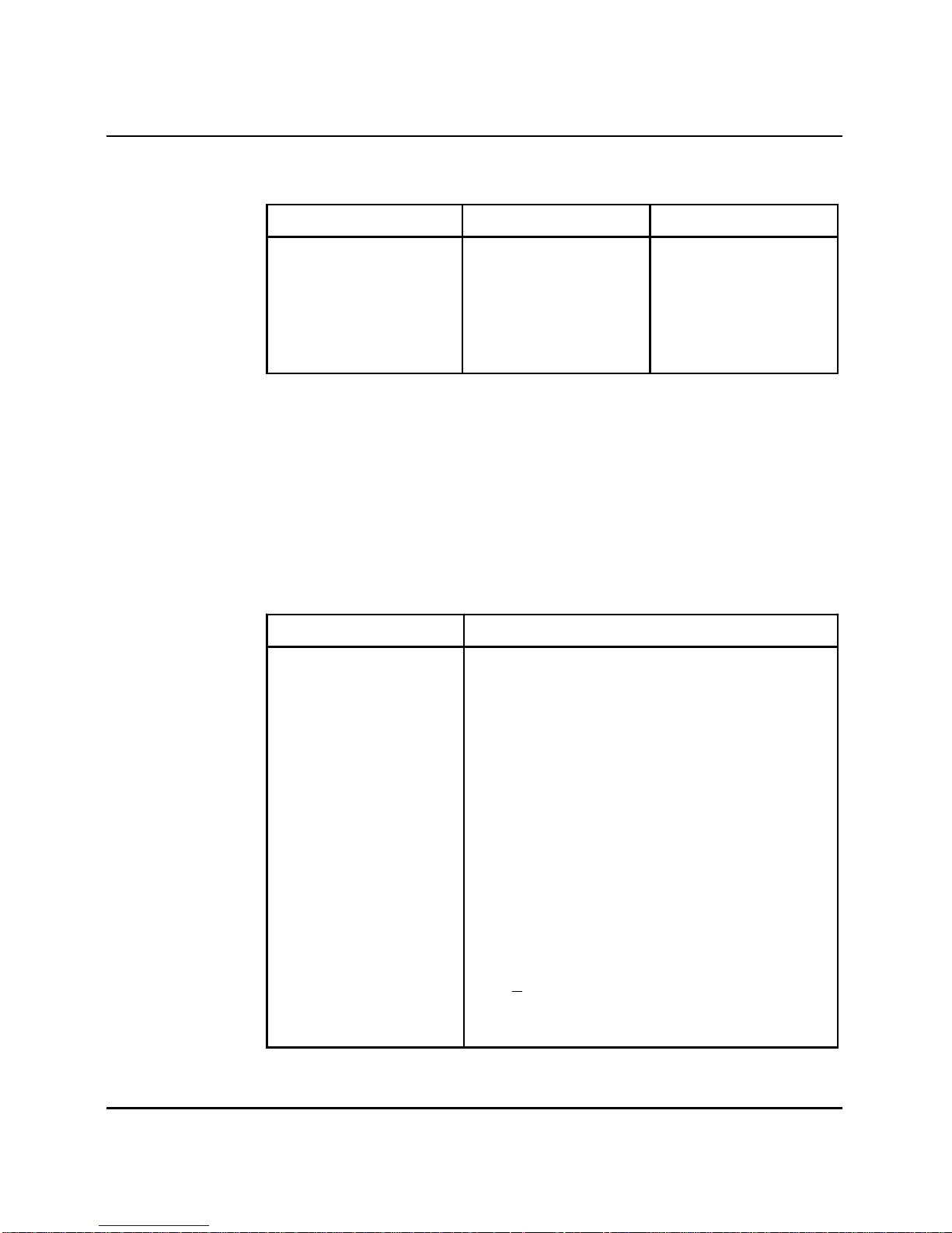
The loss values in Table 2 are measured relative to the loss at 1 kHz.
NT5K02 and NT8D03 Analog Line Cards 553-3001-161
Page 14
10 Technical summary
Table 2
NT8D03 Analog Line Card frequency response
Frequency (Hz) Minimum (dB) Maximum (dB)
60
200
300
3000
3200
3400
20.0
0.0
-0.5
-0.5
-0.5
0.0
—
5.0
1.0
1.0
1.5
3.0
Message channel noise
The message channel noise C-weighted (dBrnC) on 95 percent of the
connections (line to line) with both ends terminated in 600 ohms does not
exceed 20 dBrnC.
Table 3 provides a technical summary of the analog line card.
Table 3
NT8D03 Analog Line Card technical summary
Characteristics Description
Impedance 600 Ω
Loop limit (excluding
telephone)
1000 Ω at nominal -48 V (excluding telephone)
Leakage resistance 30,000 Ω
Ring trip During silent or ringing intervals
Ringing voltage 86 V ac
Signaling Loop start
Supervision Normal battery conditions are continuously
applied (approximately -44.5 V on ring and
-2.5 V on tip at nominal -48 V battery)
Power input from
backplane
Insertion loss 4 dB +1 dB at 1020 Hz
NT5K02 and NT8D03 Analog Line Cards 553-3001-161
-48 (can be as low as -42 for DC-powered
systems), +15, -15, +8.5 V and ringing voltage
3.5 dB loss for analog to PCM
0.5 dB loss for PCM to analog
Page 15
Power requirements
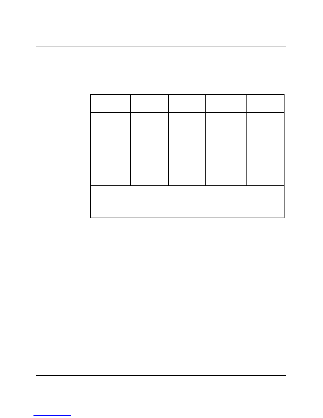
Table 4 provides the power requirements for the analog line card.
Table 4
NT8D03 Analog Line Card power requirements
Technical summary 11
Voltage
(+/-)
+15.0 V dc 0.50 V dc 48 mA 0 mA 48 mA
+8.5 V dc 1.00 V dc 150 mA 8 mA 280 mA
-48.0 V dc 2.40 V dc 48 mA 40 mA
-48.0 V dc 2.40 V dc 0 mA 10 mA
86.0 V ac 5.00 V ac 0 mA 10 mA
Note 1:
Note 2:
Note 3:
many as five ringers on each line.
Current required for each line off hook.
Each active ringing relay requires 10 mA of battery voltage.
Reflects the current for ringing a single DN telephone. There may be as
Tolerance Idle
current
Foreign and surge voltage protection
In-circuit protection against power line crosses or lightning is not provided
on the analog line card. When the card is used to service off-premise
telephones, primary and secondary MDF protection must be installed.
Off-premise telephones served by cable pairs routed through the central
office, or crossing a public right-of-way, can be subject to a requirement for
on-card protection, and MDF protectors may not be acceptable. Check local
regulations before providing such service.
Active
current
(Note 1)
(Note 2)
(Note 3)
Maximum
688 mA
320 mA
160 mA
Overload level
Signal levels exceeding +6.5 dBm0 applied to the tip and ring cause
distortion in speech transmission.
NT5K02 and NT8D03 Analog Line Cards 553-3001-161
Page 16
12 Technical summary
Backplane pin layout
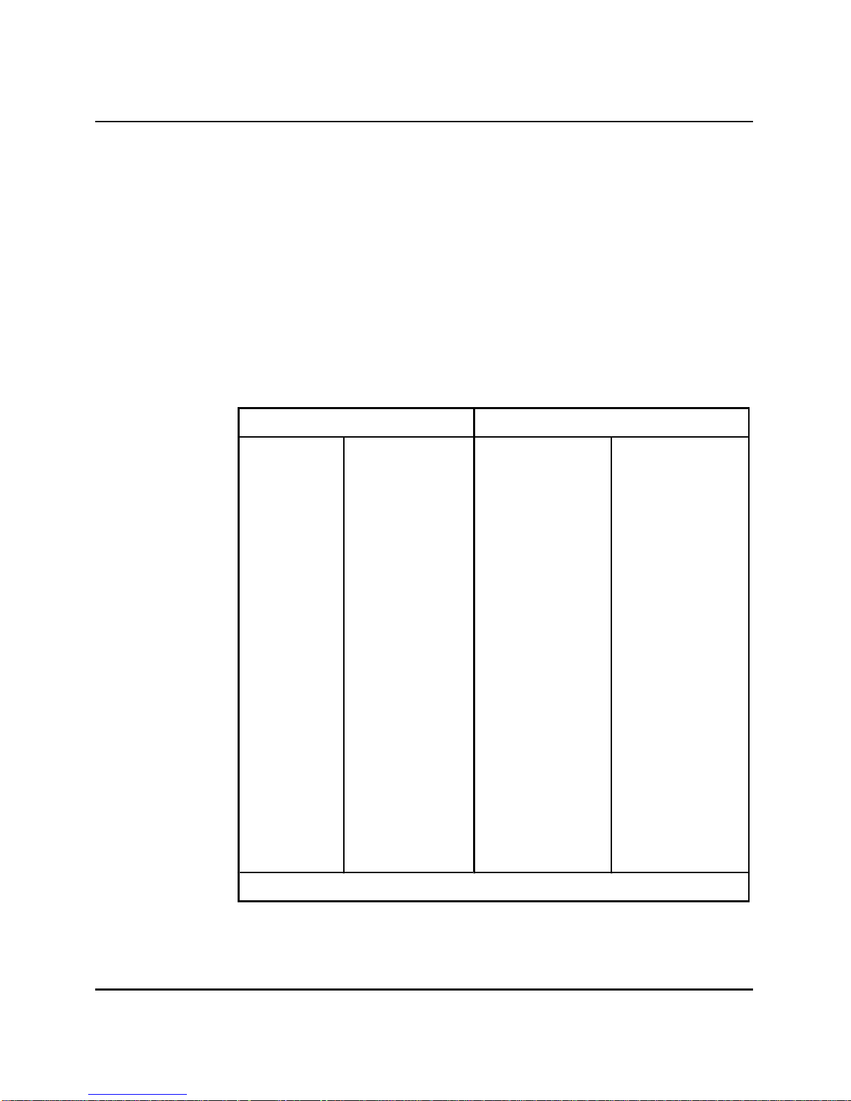
Table 5 shows the I/O pin designations at the backplane connector, which is
arranged as an 80-row by 2-column array of pins. Normally, these pin
positions are cabled to 50-pin connectors at the I/O panel in the rear of each
module, for connection with 25-pair cables to the MDF.
The information in Table 5 is provided as a reference and diagnostic aid at
the backplane, since the cabling arrangement may vary at the I/O panel. See
System installation procedures (553-3001-210) for cable pinout information
at the I/O panel.
Table 5
NT8D03 Analog Line Card backplane pinout assignments
B a ckplan e pinout L e ad de s igna t ions
12A 12B R0 T0
13A 13B R1 T1
14A 14B R2 T2
15A 15B R3 T3
16A 16B R4 T4
17A 17B R5 T5
18A 18B R6 T6
19A 18B R7 T7
62A 62B R8 T8
63A 63B R9 T9
64A 64B R10 T10
65A 65B R11 T11
66A 66B R12 T12
67A 67B R13 T13
68A 68B R14 T14
69A 69B R15 T15
Note:
These pinouts apply to both NT8D37 and NT8D11 backplanes.
NT5K02 and NT8D03 Analog Line Cards 553-3001-161
Page 17

NT5K02 Flexible Analog Line Card
Analog line interface
The technical characteristics for the NT5K02 Flexible Analog Line (A-Law)
card are comparable with those for the Analog Line card with the following
exceptions:
Input impedance
The impedance at Tip and Ring is 600 ohms with a return loss of
15 dB for 300-600 Hz
20 dB for 600-3400 Hz
Countries with termination impedances other than 600Ω are listed in Table
6:
Table 6
Termination impedances
Country Code Termination
Technical summary 13
Australia NT5K02AA 220+820//120uF
Belgium NT5K02HA 150+830//72nF
Denmark NT5K02JA 430+820//33nF
France NT5K02DA 180+910//150nF
Netherlands NT5K02KA 340+422//150nF
New Zealand NT5K02LA 370+620//310nF
Norway NT5K02MA 120+820//110nF
Sweden NT5K02NA 200+1000//100nF
Switzerland NT5K02PA 180+470//68nF
United Kingdom NT5K02QA 300+1000//220nF
Germany NT5K02EA 220+820//115nF
NT5K02 and NT8D03 Analog Line Cards 553-3001-161
Page 18

14 Technical summary
Insertion loss
On a station line-to-line connection, the total insertion loss at 1 KHz is as
listed in Table 7 with a reference level of 0 dBm0.
Table 7
Insertion losses
Country Gain (dB) Tolerance
A/D D/A A/A (dB)
A-A
France 1.4 -8.4 -7.0 +/- 0.7
Germany 0 -7.0 -7.0 +/- 0.7
Australia -1.5 -7.5 -9.0 +/- 0.7
Sweden -6.0 -5.0 -11.0 +/- 1.0
United Kingdom -3.0 -4.0 -7.0 +/-0.7
Note: Other countries may also be accommodated with component
substitution.
Frequency response
The loss values in the Table 8 below are measured relative to the loss at 1 KHz
with a reference level of -10 dBm0:
Table 8
Frequency responses
Frequency Response (Loss) A-A
Freq Australia Germany France Sweden
Min Max Min Max Min Max Min Max
200 Hz 0.0 dB - 0.0 dB - 0.0 dB - 0.0 dB 300 Hz -0.6 dB 2.0 dB -0.7 dB 2.0 db -0.6 dB 2.0 dB -0.6 dB 2.0 dB
500 Hz -0.6 dB 0.6 dB -0.7 dB 0.7 dB -0.6 dB 1.0 dB -0.6 dB 1.1 dB
3000 Hz -0.6 dB 1.0 dB -0.7 dB 0.7 dB -0.6 dB 1.0 dB -0.6dB 1.1 dB
3200 Hz -0.6 dB 2.0 dB -0.5 dB 1.5 dB -0.6 dB 2.0 dB -0.6 dB 3.0 dB
3400 Hz -0.6 dB 2.0 dB 0.0 dB 2.0 dB -0.6 dB 2.0 dB -0.6dB 3.0 dB
NT5K02 and NT8D03 Analog Line Cards 553-3001-161
Page 19

Technical summary 15
Idle channel noise
The idle channel noise (psophometric weighted) on 95% of the connections
(line to line) with both ends terminated with the appropriate termination
shall not exceed -65 dBm0p.
A technical summary of the Flexible Analog Line card is given in
Table 9.
Table 9
Technical summary
Impedance 600Ω or see Table 6
Loop limit (including set) 1000Ω at nominal -48V
1800Ω at nominal -48V
(for Australia)
Leakage resistance 30,000Ω
Ring trip During silent or ringing
intervals
Ringing voltage 86V ac
Signaling Loop start
Supervision Normal battery conditions are
Power input from shelf
backplane
Insertion loss See Table 7
Ringer limitations
Five or fewer of type NE-C4A (or equivalent) ringers per line.
No. of ringers 2 3 4 5
Note: Ring source impedance must be ≥1 kohms for Australia
including the line feed resistors.
continuously applied (-48 V on
ring; ground on tip)
See Table 10
NT5K02 and NT8D03 Analog Line Cards 553-3001-161
Page 20

16 Technical summary
Ground button detection
The ground button detector will send a “recall signal” 30-50 ms after the
application of ground through a resistance R to either Tip or Ring of a telset
connected in a balanced loop of up to 1000Ω. Resistance R may be of value
0 to 500Ω.
Power requirements
The NT5K02 Flexible Analog Line card has the following power
requirements:
Table 10
Power requirements
Voltage
(+/-)
+ 15.0 V dc 0.05 V dc 120 ma 0 ma 120 ma
- 15.0V dc 0.05 V dc 48 ma 0 ma 48 ma
+ 8.5V dc 1.00 V dc 250 ma 8 ma 280 ma
- 48.0 V dc 2.40 V dc 60 ma 40 ma 700 ma
- 48.0 V dc 2.40V dc 0 ma (1) 10 ma 320 ma
86.0 V ac 5.00 V ac 0 ma (2) 10 ma 160 ma
-120.0 V dc 5.00 V dc 0 ma 1 ma 32 ma
Tolerance Idle
current
Active
current
Max
Notes: (1) Each active ringing relay requires 10 ma of battery voltage.
(2) Reflects the current for ringing a single station set. There
may be as many as five ringers on each line.
NT5K02 and NT8D03 Analog Line Cards 553-3001-161
Page 21

SL-1
NT5K02 and NT8D03 Analog
Line Cards
Description
© 1990 Northern Telecom
All rights reserved.
Information subject to change without notice.
Meridian 1 and Digitone are trademarks of
Northern Telecom.
Release 3.1
Standard
March 1, 1992
Printed in Canada
 Loading...