

Page 1
NETCOMM GATEWAY SERIES
ADSL2+/3G Wireless N300
4-Port Modem Router
USER GUIDE
Page 2

Preface
This manual provides information related to the installation, operation, and application of this device. The individual reading this manual is
presumed to have a basic understanding of telecommunications terminology and concepts.
If you nd the product to be broken or malfunctioning, please contact technical support for immediate service by email at
technicalsupport@netcomm.com.au
For product update, new product release, manual revision, or software upgrades, please visit our website at http://www.Netcomm.com.au
Important Safety Instructions
With reference to unpacking, installation, use and maintenance of your electronic device, the following basic guidelines are recommended:
• Do not use or install this product near water, to avoid re or shock hazard. For example, near a bathtub, kitchen sink or laundry tub,
or near a swimming pool. Also, do not expose the equipment to rain or damp areas (e.g. a wet basement).
• Do not connect the power supply cord on elevated surfaces. Allow it to lie freely. There should be no obstructions in its path and no
heavy items should be placed on the cord. In addition, do not walk on, step on or mistreat the cord.
• Use only the power cord and adapter that are shipped with this device.
• To safeguard the equipment against overheating, make sure that all openings in the unit that offer exposure to air are not blocked.
• Avoid using a telephone (other than a cordless type) during an electrical storm. There may be a remote risk of electric shock from
lightening. Also, do not use the telephone to report a gas leak in the vicinity of the leak.
• Never install telephone wiring during stormy weather conditions.
WARNING
• Disconnect the power line from the device before servicing.
Copyright
Copyright©2008 NetComm Limited. All rights reserved. The information contained herein is proprietary to NetComm Limited. No part of
this document may be translated, transcribed, reproduced, in any form, or by any means without prior written consent of NetComm Limited
NOTE:This document is subject to change without notice.
Save Our Environment
When this equipment has reached the end of its useful life, it must be taken to a recycling centre and processed separate from domestic
waste.
The cardboard box, the plastic contained in the packaging, and the parts that make up this router can be recycled in accordance with
regionally established regulations. Never dispose of this electronic equipment along with your household waste. You may be subject to
penalties or sanctions under the law. Instead, ask for disposal instructions from your municipal government.
Please be responsible and protect our environment.
ADSL2+/3G Wireless N300 4-Port Modem Router YML15WN
2 www.netcomm.com.au
Page 3

NetComm Gateway Series - ADSL2+/3G Wireless N300 4-Port Modem Router
Table of Contents
Introduction ............................................................................................................................................................................................... 5
Your 3G15Wn – ADSL2+/3G Wireless N300 4-Port Modem Router ................................................................................................................................. 6
Package contents ............................................................................................................................................................................................................6
Key features ..................................................................................................................................................................................................................... 6
Placement of your 3G15Wn ...................................................................................................................................................................... 7
Router placement .............................................................................................................................................................................................................8
Avoid obstacles and interference ......................................................................................................................................................................................8
Cordless phones .............................................................................................................................................................................................................. 8
Choose the “quietest” channel for your wireless network ..................................................................................................................................................9
Product Layout ........................................................................................................................................................................................ 10
Getting to know your 3G15Wn ....................................................................................................................................................................................... 11
Minimum system requirements .......................................................................................................................................................................................12
Do I need a Microlter? ..................................................................................................................................................................................................12
Default settings ..............................................................................................................................................................................................................13
Restore factory default Settings ......................................................................................................................................................................................13
Connecting the 3G15Wn ................................................................................................................................................................................................13
Quick ADSL setup ..........................................................................................................................................................................................................14
Quick 3G setup .............................................................................................................................................................................................................. 15
Establish a wireless connection ...................................................................................................................................................................................... 15
Advanced Conguration .........................................................................................................................................................................16
What can you do from here ............................................................................................................................................................................................ 17
Logging into the user interface .......................................................................................................................................................................................17
Web User Interface .................................................................................................................................................................................. 18
What can you do from here ............................................................................................................................................................................................ 19
Logg on to the web user interface .................................................................................................................................................................................. 19
Basic ........................................................................................................................................................................................................20
Quick Setup ................................................................................................................................................................................................................... 21
Home ............................................................................................................................................................................................................................. 21
3G Settings .............................................................................................................................................................................................. 23
3G Interface ...................................................................................................................................................................................................................24
3G WAN Service ............................................................................................................................................................................................................24
PIN Conguration ........................................................................................................................................................................................................... 24
3G Backup Cong.......................................................................................................................................................................................................... 25
3G 25
Wireless ................................................................................................................................................................................................... 26
Setup/Basic ...................................................................................................................................................................................................................27
Security .......................................................................................................................................................................................................................... 28
Conguration.................................................................................................................................................................................................................. 28
MAC lter ....................................................................................................................................................................................................................... 30
Wireless bridge ..............................................................................................................................................................................................................31
Station info ..................................................................................................................................................................................................................... 31
Management ............................................................................................................................................................................................ 32
Device Settings .............................................................................................................................................................................................................. 33
Backup .................................................................................................................................................................................................................... 33
Update ....................................................................................................................................................................................................................33
Restore Default ........................................................................................................................................................................................................ 33
Update Firmware .....................................................................................................................................................................................................34
SNMP ............................................................................................................................................................................................................................34
TR-069 client .................................................................................................................................................................................................................35
SNTP .............................................................................................................................................................................................................................36
Access Control ............................................................................................................................................................................................................... 36
Services ................................................................................................................................................................................................................... 36
Passwords ............................................................................................................................................................................................................... 36
Save/Reboot .................................................................................................................................................................................................................. 37
Advanced ................................................................................................................................................................................................. 38
ATM interface ................................................................................................................................................................................................................. 39
WAN service ..................................................................................................................................................................................................................39
LAN ...............................................................................................................................................................................................................................40
NAT ................................................................................................................................................................................................................................41
Port Forwarding ....................................................................................................................................................................................................... 41
Port Triggering .........................................................................................................................................................................................................41
Security .......................................................................................................................................................................................................................... 43
IP Filtering ................................................................................................................................................................................................................ 43
Parental Control .............................................................................................................................................................................................................45
Time Restriction ....................................................................................................................................................................................................... 45
YML15WN ADSL2+/3G Wireless N300 4-Port Modem Router
www.netcomm.com.au 3
Page 4

URL lter .................................................................................................................................................................................................................. 45
Quality of Service ...........................................................................................................................................................................................................46
Queue conguration ................................................................................................................................................................................................. 46
QoS classication ....................................................................................................................................................................................................47
Routing ..........................................................................................................................................................................................................................48
Default gateway ....................................................................................................................................................................................................... 48
Static route .............................................................................................................................................................................................................. 48
Policy routing ........................................................................................................................................................................................................... 49
Dynamic router ........................................................................................................................................................................................................ 49
DNS ............................................................................................................................................................................................................................... 50
DNS server ..............................................................................................................................................................................................................50
Dynamic DNS ..........................................................................................................................................................................................................50
DSL................................................................................................................................................................................................................................ 50
UPnP ............................................................................................................................................................................................................................. 51
DNS proxy .....................................................................................................................................................................................................................51
USB Storage .................................................................................................................................................................................................................. 52
Print Server ....................................................................................................................................................................................................................52
Interface grouping ..........................................................................................................................................................................................................53
LAN ports ......................................................................................................................................................................................................................53
Status ....................................................................................................................................................................................................... 54
Diagnostics .................................................................................................................................................................................................................... 55
System Log .................................................................................................................................................................................................................... 56
Statistics ........................................................................................................................................................................................................................ 57
LAN .........................................................................................................................................................................................................................57
WAN ........................................................................................................................................................................................................................ 57
ATM ......................................................................................................................................................................................................................... 58
ADSL ....................................................................................................................................................................................................................... 58
Route ............................................................................................................................................................................................................................. 60
ARP ............................................................................................................................................................................................................................... 60
DHCP ............................................................................................................................................................................................................................60
Appendix A – Print Server ....................................................................................................................................................................... 62
Appendix B – USB Storage ..................................................................................................................................................................... 68
Legal and regulatory information ............................................................................................................................................................ 70
ADSL2+/3G Wireless N300 4-Port Modem Router YML15WN
4 www.netcomm.com.au
Page 5

INTRODUCTION
Page 6

Introduction
Your 3G15Wn – ADSL2+/3G Wireless N300 4-Port Modem Router
Congratulations on your purchase of a NetComm 3G15Wn – ADSL2+/3G Wireless N300 4-Port Modem Router. This product is a high-
performance ADSL2+ Modem Router combined with a 3G router that provides high-speed wireless N networking and Internet connectivity
for your home, ofce or public space. The NetComm 3G15Wn gives you the option to plug directly into an ADSL service to deliver Internet
to users or connect via 3G with its support for an external 3G USB Modem. The choice is yours. Both methods will allow you to share your
Internet connection amongst multiple users with either the 4 LAN ports for wired connections or via high-speed Wireless N.
The 3G15Wn also allows for a 3G Mobile Broadband connection provided by a 3G USB modem to act as a backup Internet connection to your
xed line service, providing automatic Internet failover to 3G in the event that the ADSL service fails. Should you have access to both connection
methods, the 3G15Wn will ensure you are “always on” which is vital to some individuals and business that perform Internet critical operations.
The USB port not only has the capability to support an external 3G USB Modem, but it is also able to be used for the purpose of print and
mass storage server. By simply plugging in a USB printer or a USB hard drive to the router, the functionality of these products will be able to
be shared with everyone connected to the 3G15Wn.
The 3G15Wn features the latest standards of wireless security, with wireless security enabled by default on each router. An advanced
rewall and VPN pass-through functionality allows for maximum security and caters for the encrypted Point-to-Point communications from
connected computers through the 3G15Wn to a VPN Server.
The Port Forwarding and UPnP functionality provided by the 3G15Wn make it easier for today’s Internet users to setup and congure the various
Network Port Rules needed by Internet applications such as On-Line Gaming, Peer-To-Peer le sharing and Instant Messaging services
Package contents
Your 3G15Wn contains the following items:
• 3G15Wn – ADSL2+/3G Wireless N300 4-Port Modem Router
• 12VDC, 1.5A Power Supply
• RJ-11 ADSL Line connection cable
• RJ-45 Ethernet cable
• Removable Antenna
• User Guide (on CD)
• Printed Quick Start Guide
Key features
• Fully featured ADSL2+ Modem Router
• USB port for alternative connection to the Internet via a 3G USB Modem
• Supports auto Internet failover from ADSL to 3G
• Wireless N access point – high speed wireless up to 300Mbps
• 2 Transmit and 2 Receive antennas
• 4 LAN ports for multiple wired connections
• Browser based interface for conguration and management: OS independent and easy to use
• Full wireless security - WEP, WPA, WPA2
ADSL2+/3G Wireless N300 4-Port Modem Router YML15WN
6 www.netcomm.com.au
Page 7

PLACEMENT
Page 8

Placement
Placement of your 3G15Wn
When Connecting With 3G
Just like your mobile phone, a 3G USB Modem’s location will affect its signal strength to the 3G Mobile Base Station (Cell Tower). The data
speed achievable from a 3G USB modem is relative to this signal strength, which is affected by many environmental factors. Please keep
in mind that the 3G USB Modem will need adequate signal strength in order to provide Internet connectivity whilst choosing a location to
place your 3G15Wn – ADSL2+/3G Wireless N300 4-Port Modem Router.
Similarly to the 3G USB Modem, the wireless connection between the Router and your Wi-Fi devices will be stronger the closer your
connected devices are to your Router. Your wireless connection and performance will degrade as the distance between your Router and
connected devices increases. This may or may not be directly noticeable, and is greatly affected by the individual installation environment.
If you have concerns about your network’s performance that might be related to range or obstruction factors, try moving the computer to
a position between three to ve meters from the Router in order to see if distance is the problem. If difculties persist even at close range,
please contact NetComm Technical Support.
Note: While some of the items listed below can affect network performance, they will not prohibit your wireless network from functioning; if you are concerned that your network is
not operating at its maximum effectiveness, this checklist may help.
Router placement
Place your Router as close as possible to the centre of your wireless network devices. To achieve the best wireless network coverage for
your “wireless clients” (i.e., computers with built in or USB Wireless Adapters, Laptops with Built-in Wireless, Wireless PDA / iPhone, etc):
• Ensure that your Router’s antennas are parallel to each other, and are positioned vertically (toward the ceiling). If your Router itself
is positioned vertically, point the antennas in an upward direction as much as possible.
• In multi-storey homes, place the Router on a oor that is as close to the centre of the home as possible. This may mean placing
the Router on an upper oor.
• Try not to place the Router near a cordless telephone that operates at the same radio frequency as the 3G15Wn (2.4GHz).
Avoid obstacles and interference
Avoid placing your Router near devices that may emit radio “noise,” such as microwave ovens. Dense objects that can inhibit wireless
communication include:
• Refrigerators
• Washers and/or dryers
• Metal cabinets
• Large aquariums
• Metallic-based, UV-tinted windows
If your wireless signal seems weak in some spots, make sure that objects such as these are not blocking the signal’s path (between your
devices and Router).
Cordless phones
If the performance of your wireless network is impaired after considering the above issues, and you have a cordless phone:
• Try moving cordless phones away from your Router and your wireless-enabled computers.
• Unplug and remove the battery from any cordless phone that operates on the 2.4GHz band (check manufacturer’s information). If
this xes the problem, your phone may be interfering with the Wi-Fi Router.
• If your phone supports channel selection, change the channel on the phone to the farthest channel from your wireless network.
For example, change the phone to channel 1 and move your Router to channel 11. See your phones user manual for detailed
instructions.
• If necessary, consider switching to a 900MHz or 5GHz cordless phone.
ADSL2+/3G Wireless N300 4-Port Modem Router YML15WN
8 www.netcomm.com.au
Page 9

NetComm Gateway Series - ADSL2+/3G Wireless N300 4-Port Modem Router
Choose the “quietest” channel for your wireless network
In locations where homes or ofces are close together, such as apartment buildings or ofce complexes, there may be wireless networks
nearby that can conict with your wireless network.
Use the Site Survey capabilities found in the Wireless Utility of your wireless adapter to locate any other wireless networks that are available
(see your wireless adapter’s user manual), and switch your Router and computers to a channel as far away from other networks as
possible.
• Experiment with more than one of the available channels, in order to nd the clearest connection and avoid interference from
neighbouring cordless phones or other wireless devices.
• For NetComm wireless networking products, use the detailed Site Survey and wireless channel information included with your
wireless network card. See your network card’s user guide for more information.
These guidelines should allow you to cover the maximum possible area with your Router. Should you need to cover an even wider area, you
should consider looking at building a hybrid network by combining your wireless network with a HomePlug Network. See the NetComm
website for more details on HomePlug products
YML15WN ADSL2+/3G Wireless N300 4-Port Modem Router
www.netcomm.com.au 9
Page 10

Product Layout
Page 11
NetComm Gateway Series - ADSL2+/3G Wireless N300 4-Port Modem Router
Product Layout
Getting to know your 3G15Wn
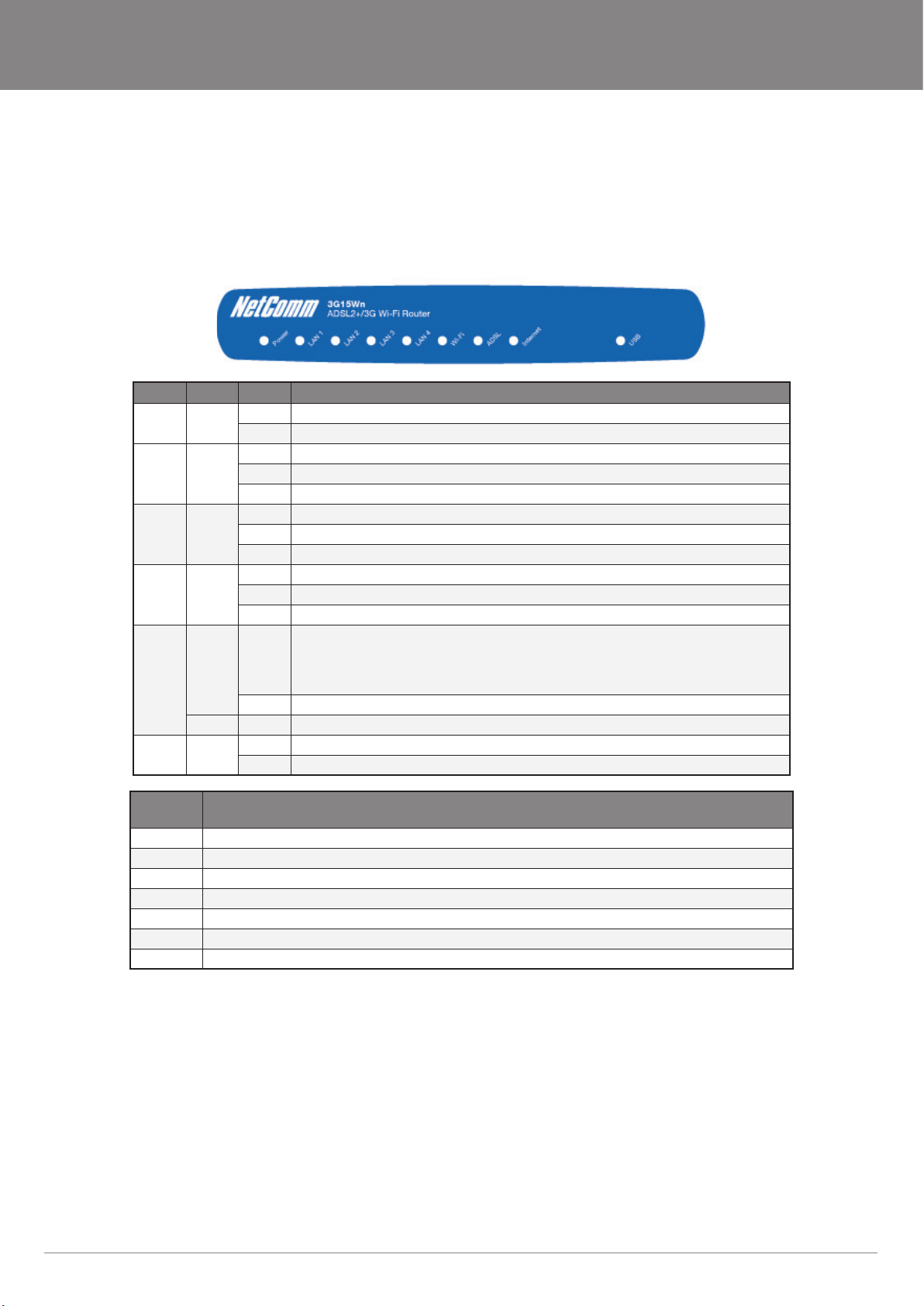
It is recommended that you take a moment to acquaint yourself with the indicator lights, ports and default settings of the 3G15Wn prior to
commencing with installation.
LED Colour Mode Function
Power Green On The router is powered on
Off The router is not powered
LAN 1-4 Green On Ethernet link is established
Off There is no Ethernet link established
Blinking Data transmitting/receiving over Ethernet
Wi-Fi Green On Wireless module is ready
Off Wireless Module is not installed
Blinking Data transmitting/receiving over Wi-Fi
ADSL Green On The ADSL link is established
Off The is no ADSL link established
Blinking The ADSL line is training if it is blinking rapidly, The ADSL line is not connected if it is blinking slowly.
Internet Red On Device attempted to obtain an IP address and failed (no DHCP response, no PPPoE response, PPPoE
Off Modem is in bridged mode or ADSL connection is not present
Green Blinking IP connected and data is passing through the device (either direction)
USB Green On A USB device is plugged into the USB port
Off There is no USB device plugged into the USB port
authentication failed, no IP address from IPCP etc.) For bridged mode, this LED remains off. If the IP or
PPPoE session is dropped due to an idle timeout, the LED will remain green if an ADSL connection is
still present. If the session is dropped for any other reason, the LED is turned off. The LED will turn red
when it attempts to reconnect and DHCP or PPPoE fails
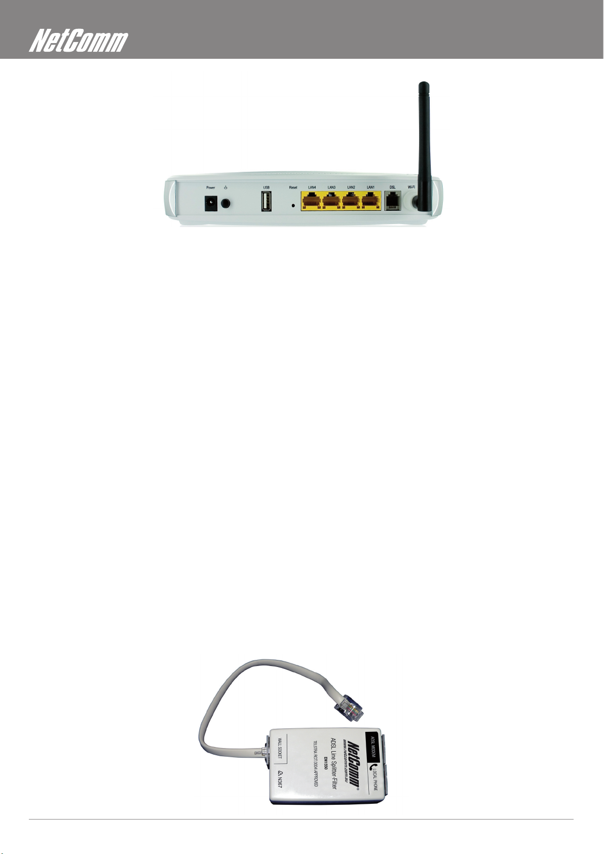
Port
Name
Power Connect the supplied power adapter
On/Off Push to turn the 3G15Wn on and off
USB Connect your external 3G USB Modem for a 3G connection or USB Storage/USB Printer
Reset Reset button. Depress for 10 seconds to return your 3G15Wn to factory default settings
LAN x 4 4 x 10/100 Ethernet switch to connect wired devices
DSL Telephone jack (RJ-11) to connect to your telephone wall socket (ADSL Line)
Wi-Fi Wi-Fi antenna for distributing wireless Internet signal
Function
YML15WN ADSL2+/3G Wireless N300 4-Port Modem Router
www.netcomm.com.au 11
Page 12
Minimum system requirements
Different aspects of the 3G15Wn have different requirements, so let’s look at them in turn. We’ll start with your computer, which ought to
match the following requirements if you are to enjoy the benets of a high-speed ADSL connection and use of 3G and Wireless Networking.
PC Requirements:
• Any computer running Windows 98/2000/Me/XP/Vista/7 or Macintosh OSX
• Ethernet or Wireless Network card
• CD-ROM drive
• Web browser e.g.
• Internet Explorer 5.1 (or better)
• Netscape Navigator
• Mozilla FireFox 1.0.4 (or better)
ADSL Requirement:
• ADSL broadband connection to an ISP (Internet Service Provider)
• ADSL In-line Splitter/Filter (Please refer to “Do I need a micro lter?” for more information)
Note: Connection at ADSL2 or 2+ rates depends on the service offered by your ISP; the device will operate at standard ADSL rates in the absence of the 2 or 2+ service.
3G Requirement:
Note: Subject to terms and conditions from your 3G Mobile Broadband Service Provider.
Wireless Computer/Device Requirements
Consult your ISP for details.
• Compatible 3G USB Modem with Active SIM/Data Service if you want to use 3G Broadband service.
• Computer/device with a working 802.11b, 802.11g or 802.11n wireless adapter.
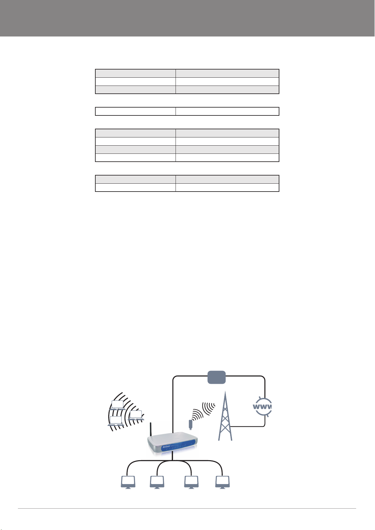
Do I need a micro lter?
Micro lters are used to prevent interference between phones and fax machines, and your ADSL service. If your ADSL-enabled phone
line is being used with any equipment other than your ADSL Modem then you will need to use one Micro lter for each phone device in
use. Telephones and/or facsimiles in other rooms that are using the same line will also require Microlters. A suitable Microlter can be
purchased from NetComm or your Service Provider, if required.
ADSL2+/3G Wireless N300 4-Port Modem Router YML15WN
12 www.netcomm.com.au
Page 13
NetComm Gateway Series - ADSL2+/3G Wireless N300 4-Port Modem Router
Default settings
LAN (Management)
Static IP Address: 192.168.1.1
Subnet Mask: 255.255.255.0
Default Gateway: 192.168.1.1
WAN (Internet)
WAN mode: DHCP
Wireless
SSID: NetComm Wireless
Channel: auto
Security: WEP, 64bit
WEP Key: a1b2c3d4e5
Interface Access
Username: admin
Password: admin
Restore Factory Default Settings
Restoring factory defaults will reset the 3G15Wn to its factory default conguration. Occasions may present themselves where you need to
restore the factory defaults on your 3G15Wn such as:
• You have lost your username and password and are unable to login to your 3G15Wn’s web conguration page;
• You have purchased your 3G15Wn from someone else and need to recongure the device to work with your ISP;
• You are asked to perform a factory reset by NetComm Support staff
In order to restore your 3G15Wn to its factory default settings, please follow these steps:
• Ensure that your 3G15Wn is powered on (for at least 10 seconds);
• Use a paper clip or a pencil tip to depress the reset button for ten seconds and release. At this point, the reset is in progress. Do not
power off the unit at this point;
• When indicator lights return to steady green, reset is complete. The default settings are now restored. The entire process takes
about 45 seconds to complete;
• Once you have reset your 3G15Wn to its default settings you will be able to access the device’s conguration web interface using
http://192.168.1.1 with username ‘admin’ and password ‘admin’;
Connecting the 3G15Wn
Telephone
ADSL2+
Exchange
3G USB Modem
300Mbps Wireless Link
3G15Wn
LAN 1 LAN 2 LAN 3 LAN 4
3G Tower
YML15WN ADSL2+/3G Wireless N300 4-Port Modem Router
www.netcomm.com.au 13
Page 14
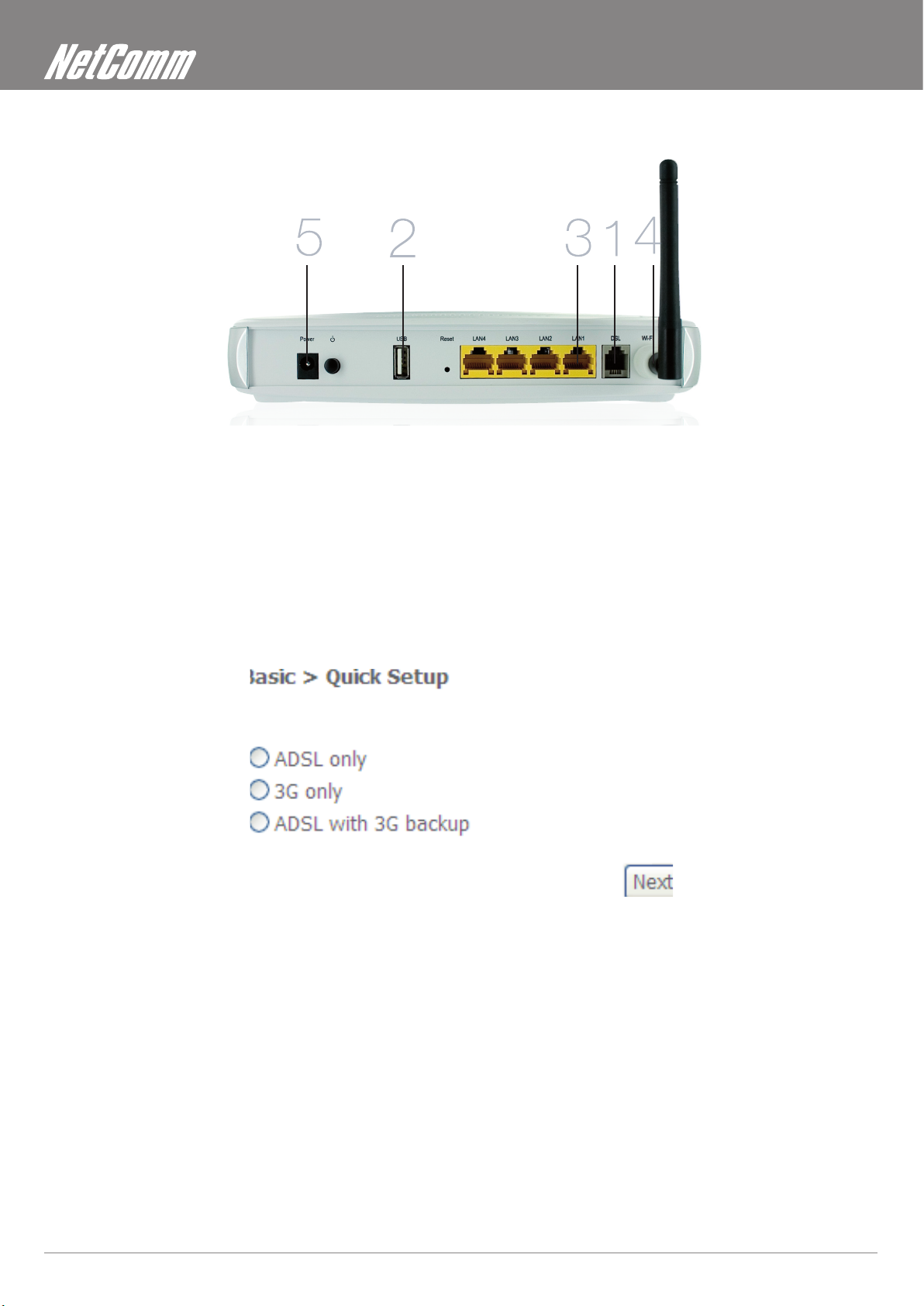
Quick Setup
1. Connect the supplied RJ-11 cable to the DSL port on the back of your router to the phone port that supplies your ADSL.
2. And/or, attach a compatible 3G USB modem into the USB port on the back of the router
3. Connect the supplied RJ-45 Ethernet cable from one of the LAN ports on the back of the router to your computer
4. Screw the supplied detachable antenna to the Wi-Fi connector on the back of the router
5. Connect the supplied power adapter to your router and press the on/off button to power the router on.
Login to the web interface
• Open a web browser (Internet Explorer, Firefox, and Safari) and type 192.168.1.1 into the address bar.
• At the login screen type admin into both the username and password elds. Then click submit. This will take you directly to the
Quick Setup page
ADSL2+/3G Wireless N300 4-Port Modem Router YML15WN
14 www.netcomm.com.au
Page 15
NetComm Gateway Series - ADSL2+/3G Wireless N300 4-Port Modem Router
Connecting With ADSL
1. Select the ADSL only box and click Next
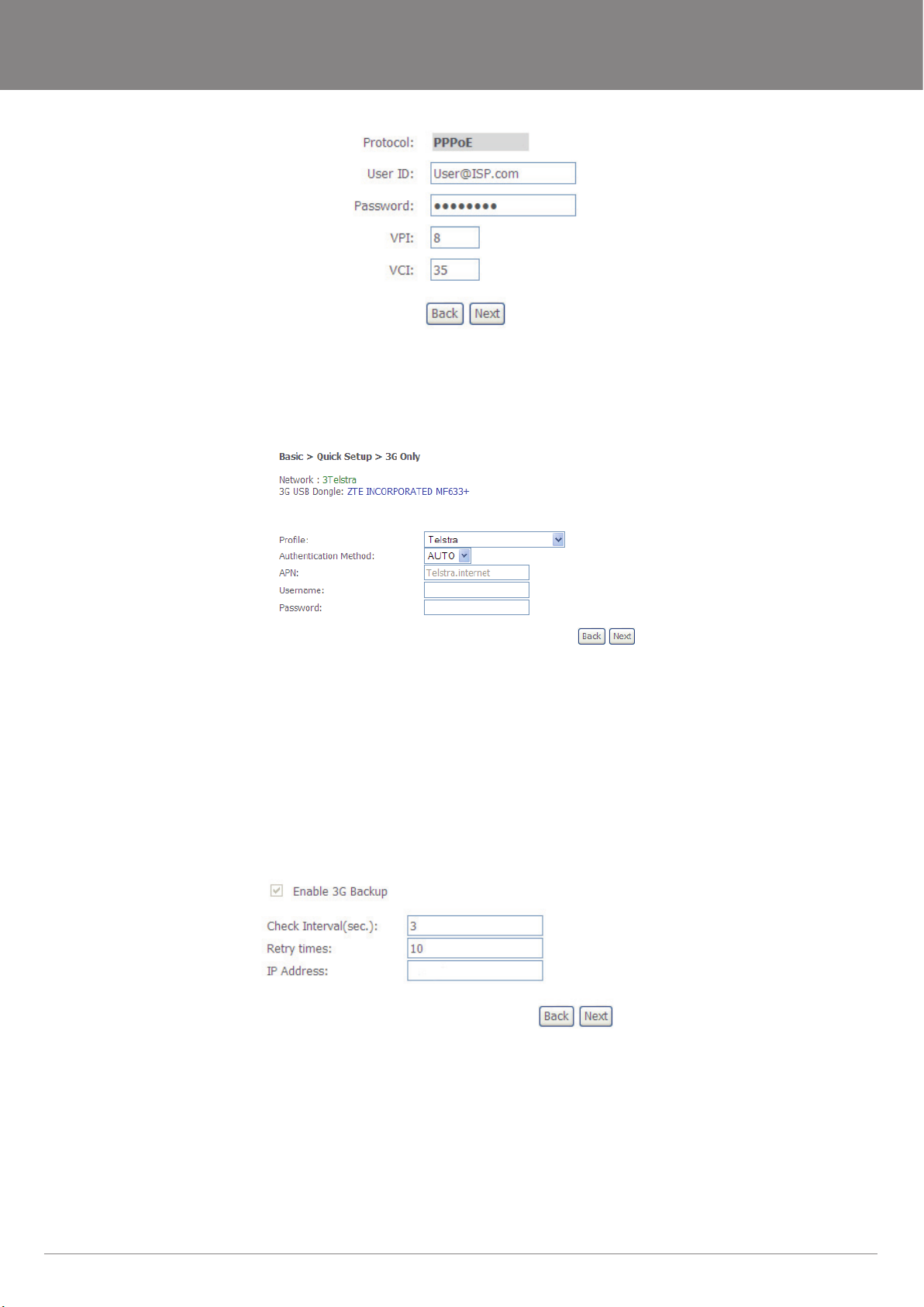
2. Enter the user ID/Password on this screen as supplied by your ISP
3. Click on Next to use these settings
4. You will then be asked to enter additional setup details.
Connecting with 3G
1. Select the 3G only box and click Next
2. Your modem will auto detect if it is compatible: This information can be seen at the top of the page
3. From the drop down Prole box select your 3G ISP, which will auto-ll your APN setting
4. Enter the username/password supplied by your 3G ISP.
Note: Not all 3G users will have a username/password. Only enter this information if you have been supplied one by your 3G ISP
5. Click on Next to use these settings
6. You will then be asked to enter additional setup details. This will be explained from Wireless Quick Setup
Conguring 3G backup
1. Select the ADSL with 3G backup box and click Next
2. Follow the instructions listed above for both ADSL and 3G to set up both connections
3. Check the Enable 3G Backup box and enter your desired backup settings
4. Click on Next to use these settings
5. You will then be asked to enter additional setup details. This will be explained from Wireless Quick Setup
YML15WN ADSL2+/3G Wireless N300 4-Port Modem Router
www.netcomm.com.au 15
Page 16
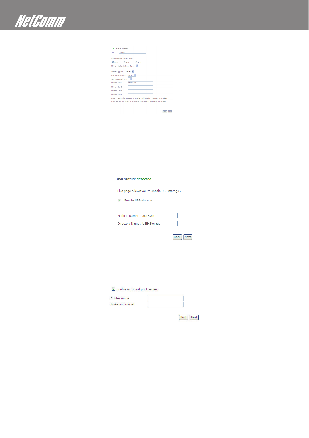
Wireless Quick Setup
1. All the default settigns already appear on the wireless quick setup page
2. You can enable/disable your wireless
3. You can change your wireless SSID. If you do, be sure to remember the new name or write it down so you know what network to
connect to
4. You can also select the level of wireless security and change the wireless password
5. Once you have completed entering your wireless settings click Next
USB Storage
1. If a USB device is plugged into the USB port, it will be detected and you will have the choice to Enable USB storage
2. If you enable USB storage you will be shown the netbios and Directory name, you can change these to anything you want
3. Click Next once you are happy with the settings
4. To access the storage device open a web browser and type \\Netbios\Directory\. So using the defaults \\3G15Wn\USB-
Storage\
USB Print Server
1. If a USB device is plugged into the USB port, it will be detected and you will have the choice to Enable on-board print server
2. If you enable the device to work as a print server you will be asked to enter the printer name and make and model. Both elds
can be named anything you like. The names will be used to identify the printer later.
3. Click Next once you are happy with the settings
4. To complete setting up your network printer, please read Appendix A of the User Manual
ADSL2+/3G Wireless N300 4-Port Modem Router YML15WN
16 www.netcomm.com.au
Page 17

NetComm Gateway Series - ADSL2+/3G Wireless N300 4-Port Modem Router
Passwords
1. On this page you can change the passwords for the different levels of users
2. The default password for all users is the same as the corresponding username
3. Once you have completed setting the passwords click Finish
4. You will be taken back to the home page where you can view your connection status
Establishing a Wireless Connection
You can connect multiple wireless devices, including laptops, desktops and PDA’s to your device by following these two basic steps.
1. Using your wireless device, scan the wireless networks in your area and select the network called NetComm Wireless, then click
connect.
Note: If you changed the SSID in the wireless quick setup, then your network name will be different
2. Enter the following default security key: a1b2c3d4e5
Note: To ensure wireless security, we recommend that you change the default settings through the web Interface.
If you changed the wireless password in the wireless quick setup, then your security key will be different
Troubleshooting
Cannot establish a wireless connection
• Make sure the wireless switch on your laptop is in the on position
• Ensure your device and wireless adapter are using the same wireless security settings
• Make sure you are trying to connect to the correct SSID with the correct
security key
Cannot establish an ADSL connection
• Ensure you have entered the correct username and password as supplied by your ISP. If you cannot nd them please contact
your ISP to ensure you have the correct details.
Cannot establish a 3G Connection
• Ensure you are using a compatible 3G USB Modem
Note: See NetComm Website for a list of compatible modems - www.netcomm.com.au
• Ensure you have entered the correct 3G Prole (ISP name and pre/post paid) and that the APN is the same as supplied by your
3G ISP
Cannot access the Web UI
• If you have changed your username/password and forgotten them you will need to reset your router to the factory default settings
and use the default settings admin/admin
How to reset your router to the factory default settings
• With a paperclip, sharp pencil or similar object press the reset button on the back panel of the device and hold for approximately
10 seconds.
YML15WN ADSL2+/3G Wireless N300 4-Port Modem Router
www.netcomm.com.au 17
Page 18

Web User Interface
Page 19
NetComm Gateway Series - ADSL2+/3G Wireless N300 4-Port Modem Router
Web User Interface
What can you do from here?
By logging into the web user interface, you are able to congure your 3G15Wn with a wide array of basic and advanced settings. From
setting wireless security, to backing up your routers settings, uploading new rmware and setting parental controls, the web user interface
is a handy tool for personalizing your device to maximize its potential. See below, in the rest of this user manual for a more advanced
description on all elements of the web user interface
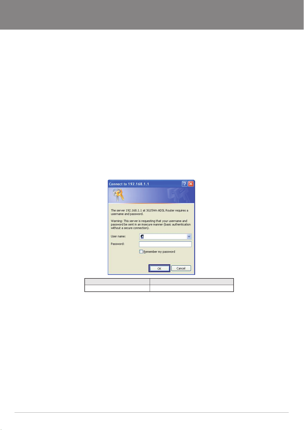
Logging into the user interface
To login to the web interface, follow the steps below:
NOTE: The default settings can be found in Default Settings, listed earlier in this manual.
1: Open a web browser and enter the default IP address for the Router in the web address eld. In this case http://192.168.1.1
NOTE: For local administration (i.e. LAN access), the PC running the browser must be attached to the Ethernet, and not necessarily to the device. For remote access, use the
WAN IP address shown on the WUI Homepage screen and login with remote username and password.
2: A dialog box will appear, as illustrated below. Enter the default username and password, as dened in the section Default Settings.
Click OK to continue.
Username: admin
Password: admin
NOTE: The login password can be changed later (see Access Control > Passwords)
3: After successfully logging in for the rst time, you will reach this following “Quick Setup” page.
YML15WN ADSL2+/3G Wireless N300 4-Port Modem Router
www.netcomm.com.au 19
Page 20

Basic
Page 21
NetComm Gateway Series - ADSL2+/3G Wireless N300 4-Port Modem Router
Basic
Quick Setup
After you log into the web user interface, you will be taken directly to the Quick Setup page. See the instructions listed above in “Quick
Setup” for instruction on how to congure your device for use.
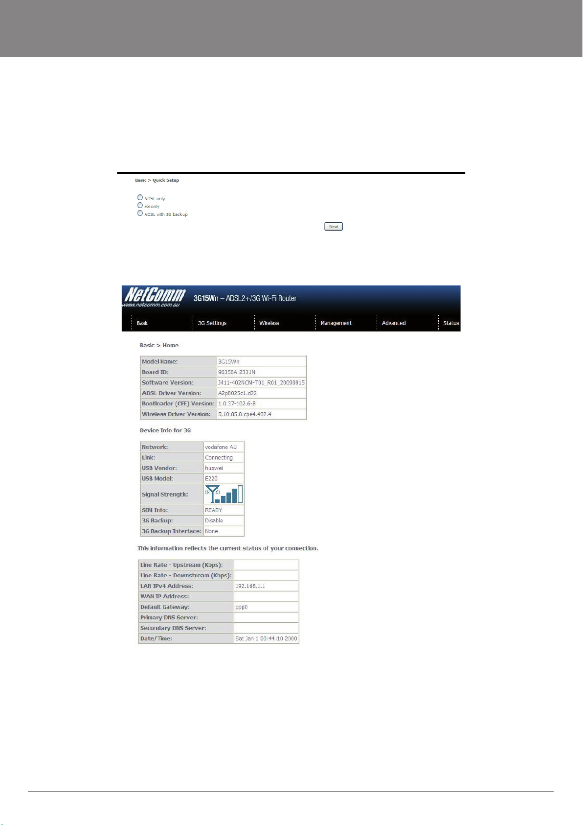
Home
The web user interface (WUI) is divided into two window panels, the main menu (on the top) and the display screen (on the bottom). The
main menu has the following options: Basic, 3G Settings, Wireless, Management, Advanced and Status.
Selecting one of these options will open a submenu with more options. Basic is discussed below while subsequent chapters introduce the
other main menu selections.
NOTE: The menu options available within the web user interface are based upon the device conguration and user privileges (i.e. local or remote).
YML15WN ADSL2+/3G Wireless N300 4-Port Modem Router
www.netcomm.com.au 21
Page 22

The following table provides further details:
Field Description
Model Name Model number of your device
Board ID The unique number of the board inside your device
Software Version The current version of software loaded on your device
ADSL Driver Version The current ADSL driver version loaded on your device
Bootloader (CFE) Version The version of the bootloader
Wireless Driver Version The current version of wireless driver being used by your device
Device Info For 3G
Network The name of your 3G network
Link The status of your 3G connection
USB Vendor The manufacturer of the inserted 3G USB modem
USB Model The manufacturers model number of the inserted 3G USB modem
Signal Strength The level of signal that your 3G USB modem is receiving from your 3G service provider
SIM Info Indicates whether or not your SIM card is activated and ready for use
3G Backup Indicates whether you have set the 3G USB modem to act as failover for your ADSL
3G Backup Interface Indicates the WAN interface that is to be back up
Line Rate - Upstream The upstream line rate in Kbps (e.g. 256 Kbps)
Line Rate - Downstream The downstream line rate in Kbps (e.g. 1500 Kbps)
LAN IPv4 Address The IP address to access the 3G15Wn on the LAN side
WAN IP Address
Default Gateway
Primary DNS Server
Secondary DNS Server
connection
The IP address to access the 3G15Wn on the WAN side
The default gateway that your 3G15Wn communicates with
The primary DNS server IP address
The secondary DNS server IP address
ADSL2+/3G Wireless N300 4-Port Modem Router YML15WN
22 www.netcomm.com.au
Page 23

3G Settings
Page 24

3G Settings
3G Interface
On this screen you are able to select the 3G USB modem that you wish to use as your Internet connection. The eld will auto ll with any
compatible 3G USB modem
3G WAN Service
From the 3G WAN Service page you are able to setup your 3G connection with advanced settings. Simply press Add to manually congure
advanced settings for your 3G connection. You can add as many different congurations as you like. If you would like to remove any
congurations at any time, tick the remove box and press the remove button.
PIN Conguration
This screen allows for changes to the 3G SIM card PIN code protection settings.
NOTE: If you have entered the incorrect PIN 3 times, your SIM card will be locked for your security. Please call your 3G Provider for assistance.
PIN Code Protection
PIN code protection prevents the use of a SIM card by unauthorized persons. To use the 3G internet service with this router however, the
PIN code protection must be disabled. If the SIM card inserted into the Router is locked with a PIN code, the web user interface will display
the following screen after login.
PIN Lock Off
If you wish to connect to the Internet using a PIN locked SIM card, you must rst turn PIN code protection Off. Select PIN lock Off, enter
the PIN Code twice. Please keep in mind you only have 3 attempts before your SIM card is locked. The remaining attempts’ number shows
how many attempts left. Contact Telstra if you require assistance. You can select Remember PIN Code to ON so you don’t need to input
the PIN code every time when the router turns on. Afterwards, click Apply. The following dialog box should now appear.
PIN Code Change
If you wish to change your PIN code for greater security, enable the PIN Code protection. Go to the previous section and follow the
procedure listed under PIN Lock On.
After locking the SIM card, select PIN Code Change and enter your Old and New PIN codes in the elds provided. Keep in mind you only
have 3 attempts before your SIM card is locked. The remaining attempts’ number shows how many attempts left. Contact Telstra if you
require assistance. Afterwards, click Apply to activate the change.
ADSL2+/3G Wireless N300 4-Port Modem Router YML15WN
24 www.netcomm.com.au
Page 25

NetComm Gateway Series - ADSL2+/3G Wireless N300 4-Port Modem Router
3G Backup Cong
On this page you are able to congure your 3G15Wn to use 3G as a backup to ADSL. Therefore if you have both connection options
available, should your ADSL connection fail, for whatever reason, then your 3G will automatically kick in to ensure you remain connected to
the Internet
Option Description
Enable 3G backup Check this box to enable your 3G15Wn to work with 3G backup
Check Interval The time in seconds that you 3G15Wn will check continuously for your ADSL
Retry times How many times the 3G15Wn will retry
IP address The Public IP address that you would like to use for checking the ADSL Internet
Selected WAN Interface The WAN interface that you would like to backup with 3G
Internet Connection.
connection by Pinging
3G
Allows you to set your preferred network type. You can choose between 3G only, GPRS (2G) only, 3G preferred and GPRS (2G) preferred.
YML15WN ADSL2+/3G Wireless N300 4-Port Modem Router
www.netcomm.com.au 25
Page 26

Wireless
Page 27

NetComm Gateway Series - ADSL2+/3G Wireless N300 4-Port Modem Router
Wireless
Setup/Basic
The Wireless submenu provides access to Wireless Local Area Network (WLAN) conguration settings including:
• Wireless network name (SSID)
• Channel restrictions (based on country)
• Security
• Access point or bridging behaviour
• Station information
This screen allows you to congure basic features of the wireless LAN interface. You can enable or disable the wireless LAN interface,
hide the network from active scans, set the wireless network name (also known as SSID) and restrict the channel set based on country
requirements. The Wireless Guest Network function adds extra networking security when connecting to remote hosts.
Option Description
Enable Wireless A checkbox that enables (default) or disables the wireless LAN interface. When selected,
Hide Access Point Select Hide Access Point to protect the access point from detection by wireless active
Clients Isolation 1. Prevents clients PC from seeing one another in My Network Places or Network
Disable WMM
Advertise
Enable WMF Stops the router from ‘advertising’ its Wireless Multimedia (WMM) functionality, which
SSID
[1-32 characters]
BSSID The BSSID is a 48bit identity used to identify a particular BSS (Basic Service Set) within
Country A drop-down menu that permits worldwide and specic national settings. Each country
Wireless Guest
Network
the Web UI displays Hide Access point, SSID, BSSID and Country settings.
scans. To check AP status in Windows XP, open Network Connections from the start
Menu and select View Available Network Connections. If the access point is hidden, it will
not be listed there. To connect a client to a hidden access point, the station must add the
access point manually to its wireless conguration.
Neighborhood.
2. Prevents one wireless client communicating with another wireless client.
Stops the router from ‘advertising’ its Wireless Multimedia (WMM) functionality, which
provides basic quality of service for time-sensitive applications (e.g. VoIP, Video).
provides basic quality of service for time-sensitive applications (e.g. VoIP, Video).
Sets the wireless network name. SSID stands for Service Set Identier. All stations must
be congured with the correct SSID to access the WLAN. If the SSID does not match,
that user will not be granted access.
an area. In Infrastructure BSS networks, the BSSID is the MAC (Media Access Control)
address of the AP (Access Point) and in Independent BSS or ad hoc networks, the BSSID
is generated randomly.
listed below enforces specic regulations limiting channel range:
• Australia = 1-13
The Guest SSID (Virtual Access Point) can be enabled by selecting the Enable Wireless
Guest Network checkbox. Rename the Wireless Guest Network as you wish.
NOTE: Remote wireless hosts cannot scan Guest SSIDs.
YML15WN ADSL2+/3G Wireless N300 4-Port Modem Router
www.netcomm.com.au 27
Page 28

Security
Security settings are used to prevent unauthorised connection to your network. This can be as basic as a neighbouring user who detects
and is able to connect through your wireless network, right through to actual malicious interference or ‘hacking’. Whatever the case, it is a
good practice to be aware of and to use wireless network security to safeguard your data and your network.
Prior to considering the details of wireless security – provided later – the Quick Security Setup explains how to implement basic security on
your 3G15Wn wireless network
Option Description
Select SSID Pre congured to the default of NetComm Wireless. Can be changed in the Wireless >
Network Authentication Here, you can select the type of wireless security you desire
WEP Encryption The option to enable or disable your wireless security encryption
Encryption Strength The strength/length of your wireless security key. 64 bit is default
Current Network Key The current network key that is active. You have the choice of setting up to 4 different
Network Key 1 The value of network key 1. Default value is a1b2c3d4e5
Network Key 2 The value of network key 2
Network Key 3 The value of network key 3
Network key 4 The value of network key 4
Setup section
wireless security keys
Conguration
The following screen appears when you select Conguration. This screen allows you to control the following advanced features of the
Wireless Local Area Network (WLAN) interface:
• Select the channel which you wish to operate from
• Force the transmission rate to a particular speed
• Set the fragmentation threshold
• Set the RTS threshold
• Set the wake-up interval for clients in power-save mode
• Set the beacon interval for the access point
• Set Xpress mode
• Program short or long preambles
ADSL2+/3G Wireless N300 4-Port Modem Router YML15WN
28 www.netcomm.com.au
Page 29

NetComm Gateway Series - ADSL2+/3G Wireless N300 4-Port Modem Router
Click Save/Apply to set the advanced wireless conguration
Option Description
Band The new amendment allows IEEE 802.11g units to fall back to speeds of 11 Mbps, so IEEE 802.11b and IEEE 802.11g devices can coexist in the same
Channel Allows selection of a specic channel (1-14) or Auto mode.
Auto Channel
Timer
802.11n/EWC An equipment interoperability standard setting based on IEEE 802.11n Draft 2.0 and Enhanced Wireless Consortium (EWC)
Bandwidth Drop-down menu species the following bandwidth: 20MHz in 2.4G Band and 40 MHz in 5G Band, 20MHz in both bands and 40MHz in both bands
Control Sideband
802.11n Rate Drop-down menu species the following xed rates. The maximum rate for bandwidth, 20MHz, is 130MHz and the maximum bandwidth, 40MHz, is
802.11n Protection Turn off for maximized throughput. Turn on for greater security
Support 802.11n
Client Only
54g Rate In Auto (default) mode, your Router uses the maximum data rate and lowers the data rate dependent on the signal strength. The appropriate setting is
Multicast rate Setting for multicast packet transmission rate. (1-54 Mbps)
Basic Rate Sets basic transmission rate.
Fragment
Threshold
RTS Threshold Request To Send (RTS) species the packet size that exceeds the specied RTS threshold, which then triggers the RTS/CTS mechanism. Smaller
DTIM Interval Delivery Trafc Indication Message (DTIM) is also known as Beacon Rate. The entry range is a value between 1 and 65535. A DTIM is a countdown
Beacon Interval The amount of time between beacon transmissions in is milliseconds. The default is 100 ms and the acceptable range is 1 – 65535. The beacon
Global Max Clients Here you have the option of setting the limit of the number of clients who can connect to your wireless network
Xpress Technology Broadcom’s Xpress™ Technology is compliant with draft specications of two planned wireless industry standards. It has been designed to improve
Transmit Power The option of decreasing the transmitting power of your wireless signal
WMM You can choose the enable or disable WMM which allows for priority of certain data over the wireless network
WMM No
Acknowledgement
network. The two standards apply to the 2.4 GHz frequency band. IEEE 802.11g creates data-rate parity at 2.4 GHz with the IEEE 802.11a standard,
which has a 54 Mbps rate at 5 GHz. (IEEE 802.11a has other differences compared to IEEE 802.11b or g, such as offering more channels.)
The Auto Channel times the length it takes to scan in minutes.
This is available for 40MHz. Drop-down menu allows selecting upper sideband or lower sideband
270MHz
The option to provide wireless Internet access only to clients who are operating at 802.11n speeds
dependent on signal strength. Other rates are discrete values between 1 to 54 Mbps.
A threshold (in bytes) determines whether packets will be fragmented and at what size. Packets that exceed the fragmentation threshold of an 802.11
WLAN will be split into smaller units suitable for the circuit size. Packets smaller than the specied fragmentation threshold value however are not
fragmented.
Values between 256 and 2346 can be entered but should remain at a default setting of 2346. Setting the Fragmentation Threshold too low may result in
poor performance.
packets are sent without using RTS/CTS. The default setting of 2347 (max length) will disables the RTS Threshold.
variable that informs clients of the next window for listening to broadcast and multicast messages. When the AP has buffered broadcast or multicast
messages for associated clients, it sends the next DTIM with a DTIM Interval value. AP Clients hear the beacons and awaken to receive the broadcast
and multicast messages. The default is 1.
transmissions identify the presence of an access point. By default, network devices passively scan all RF channels listening for beacons coming from
access points. Before a station enters power save mode, the station needs the beacon interval to know when to wake up to receive the beacon.
wireless network efciency. Default is disabled
Refers to the acknowledge policy used at the MAC level. Enabling No Acknowledgement can result in more efcient throughput but higher error rates in a
noisy Radio Frequency (RF) environment
WMM APSD Automatic Power Save Delivery. Enable this to save power
YML15WN ADSL2+/3G Wireless N300 4-Port Modem Router
www.netcomm.com.au 29
Page 30

MAC lter
This screen appears when Media Access Control (MAC) Filter is selected. This option allows access to be restricted based upon the unique
48-bit MAC address.
To add a MAC Address lter, click the Add button shown below.
To delete a lter, select it from the table below and click the Remove button.
Option Description
MAC Restrict Mode Disabled – Disables MAC ltering
Deny Rejects access for the specied MAC addresses
MAC Address Lists the MAC addresses subject to the MAC Restrict Mode. The Add button prompts an
Enter the MAC address on the screen below and click Save/Apply.
Allow: Permits access for the specied MAC addresses
NOTE: Add a wireless device’s MAC address before clicking the Allow radio button or else
you will need to connect to the Router’s web user interface using the supplied yellow Ethernet
cable and add the wireless device’s MAC address.
entry eld that requires you type in a MAC address in a two-character, 6-byte convention: xx:
xx:xx:xx:xx:xx where xx are hexadecimal numbers. A maximum of 60 MAC addresses can be
added.
ADSL2+/3G Wireless N300 4-Port Modem Router YML15WN
30 www.netcomm.com.au
Page 31

NetComm Gateway Series - ADSL2+/3G Wireless N300 4-Port Modem Router
Wireless bridge
The following screen appears when selecting Wireless Bridge, and goes into a detailed explanation of how to congure wireless bridge
features of the wireless LAN interface.
Click Save/Apply to implement new conguration settings.
Option Description
AP Mode Selecting Wireless Bridge (Wireless Distribution System) disables Access Point (AP) functionality
Bridge Restrict Selecting Disabled in Bridge Restrict disables Wireless Bridge restriction, which means that any
while selecting Access Point enables AP functionality. In Access Point mode, wireless bridge
functionality will still be available and wireless stations will be able to associate to the AP.
wireless bridge will be granted access. Selecting Enabled or Enabled (Scan) allows wireless bridge
restriction. Only those bridges selected in Remote Bridges will be granted access. Click Refresh to
update the station list when Bridge Restrict is enabled.
Station info
The following screen appears when you select Station Info, and shows authenticated wireless stations and their status.
Click the Refresh button to update the list of stations in the WLAN.
Option Description
MAC The MAC address of any connected client
Associated Lists all the stations that are associated with the Access Point, along with the amount of time
Authorized Lists those devices with authorized access.
SSID The SSID of your wireless network
Interface The wireless interface being used to connect
since packets were transferred to and from each station. If a station is idle for too long, it is
removed from this list.
YML15WN ADSL2+/3G Wireless N300 4-Port Modem Router
www.netcomm.com.au 31
Page 32

Management
Page 33

NetComm Gateway Series - ADSL2+/3G Wireless N300 4-Port Modem Router
Management
Device Settings
The Device Settings screens allow you to backup, retrieve and restore the default settings of your Router. It also provides a function for you
to update your Routers rmware.
Backup
The following screen appears when Backup is selected. Click the Backup Settings button to save the current conguration settings.
You will be prompted to dene the location of a backup le to save to your PC.
Update
The following screen appears when selecting Update from the submenu. By clicking on the Browse button, you can locate a previously
saved lename as the conguration backup le. Click on the Update settings to load it
Restore Default
The following screen appears when selecting Restore Default. By clicking on the Restore Default Settings button, you can restore your
Routers default rmware settings. To restore system settings, reboot your Router.
NOTE: The default settings can be found in the section Default Settings.
Once you have selected the Restore Default Settings button, the following screen will appear. Close the window and wait 2 minutes before
reopening your browser. If required, recongure your PCs IP address to match your new conguration (see section 3.2 TCP/IP Settings for
details).
After a successful reboot, the browser will return to the Device Info screen. If the browser does not refresh to the default screen, close and
restart the browser.
NOTE: The Restore Default function has the same effect as the reset button. The device board hardware and the boot loader support the reset to default button. If the reset button
is continuously pushed for more than 5 seconds (and not more than 12 seconds), the boot loader will erase the conguration settings saved on ash memory.
YML15WN ADSL2+/3G Wireless N300 4-Port Modem Router
www.netcomm.com.au 33
Page 34

Update Firmware
The following screen appears when selecting Update Firmware. By following this screens steps, you can update your Routers rmware.
Manual device upgrades from a locally stored le can also be performed using the following screen.
1: Obtain an updated software image le
2: Enter the path and lename of the rmware image le in the Software File Name eld or click the Browse button to locate the
image le.
3: Click the Update Software button once to upload and install the le.
NOTE: The update process will take about 2 minutes to complete. The Router will reboot and the browser window will refresh to the default screen upon successful
installation. It is recommended that you compare the Software Version at the top of the Basic screen (WUI homepage) with the rmware version installed, to conrm the
installation was successful.
SNMP
The Simple Network Management Protocol (SNMP) allows a network administrator to monitor a network by retrieving settings on remote
network devices. To do this, the administrator typically runs an SNMP management station program such as MIB browser on a local host
to obtain information from the SNMP agent, in this case the 3G15Wn (if SNMP enabled). An SNMP ‘community’ performs the function of
authenticating SNMP trafc. A ‘community name’ acts as a password that is typically shared among SNMP agents and managers.
Option Description
Read Community Read device settings
Set Community Read and change device settings
System Name Default = 3G15Wn
System Location User dened value
System Contact User dened value
Trap Manager IP IP address of admin machine
ADSL2+/3G Wireless N300 4-Port Modem Router YML15WN
34 www.netcomm.com.au
Page 35

NetComm Gateway Series - ADSL2+/3G Wireless N300 4-Port Modem Router
TR-069 client
WAN Management Protocol (TR-069) allows an Auto-Conguration Server (ACS) to perform auto-conguration, provision, collection, and
diagnostics to this device.
Option Description
Inform Disable/Enable TR-069 client on the CPE
Inform Interval The duration in seconds of the interval for which the CPE MUST attempt to connect with the
ACS URL URL for the CPE to connect to the ACS using the CPE WAN Management Protocol. This
ACS User Name Username used to authenticate the CPE when making a connection to the ACS using the
ACS Password Password used to authenticate the CPE when making a connection to the ACS using the
WAN Interface used
by TR-069 client
Connection Request
Authentication
Connection Request
User Name
Connection Request
Password
Connection Request
URL
ACS and call the Inform method
parameter MUST be in the form of a valid HTTP or HTTPS URL. An HTTPS URL indicates
that the ACS supports SSL. The “host” portion of this URL is used by the CPE for validating
the certicate from the ACS when using certicate-based authentication
CPE WAN Management Protocol. This username is used only for HTTP-based authentication
of the CPE.
CPE WAN Management Protocol. This password is used only for HTTP-based authentication
of the CPE
Choose which WAN interface that TR-069 would use for communication with TR-069 Server.
Enable/Disable authentication of ACS making a Connection Request to the CPE.
Username used to authenticate an ACS making a connection request to the CPE
Password used to authenticate an ACS making a connection request to the CPE
URL used to authenticate an ACS making a connection request to the CPE
YML15WN ADSL2+/3G Wireless N300 4-Port Modem Router
www.netcomm.com.au 35
Page 36

SNTP
This screen allows you to congure the time settings of your Router.
Option Description
First NTP timeserver: Select the required server.
Second NTP timeserver: Select second timeserver, if required.
Time zone offset: Select the local time zone.
NOTE: SNTP must be activated to use Parental Control
Access Control
The Access Control option found in the Management drop down menu, congures access related parameters in the following three areas:
• Services
• Passwords
• Save/Reboot
Access Control is used to control local and remote management settings for your Router.
Services
The Service Control List (SCL) allows you to enable or disable your Local Area Network (LAN) or Wireless Area Network (WAN) services by
ticking the checkbox as illustrated below. These access services are available: FTP, HTTP, ICMP, SNMP, SSH, TELNET, and TFTP. Click
Save/Apply to continue.
ADSL2+/3G Wireless N300 4-Port Modem Router YML15WN
36 www.netcomm.com.au
Page 37

NetComm Gateway Series - ADSL2+/3G Wireless N300 4-Port Modem Router
Passwords
The Passwords option congures your account access password for your Router. Access to the device is limited to the following three user
accounts:
• admin is to be used for local unrestricted access control
• support is to be used for remote maintenance of the device
• user is to be used to view information and update device rmware
Use the elds illustrated in the screen below to change or create your password. Passwords must be 16 characters or less with no spaces.
Click Save/Apply to continue.
Save/Reboot
This function saves the current conguration settings and reboots your Router.
NOTE 1: It may be necessary to recongure your TCP/IP settings to adjust for the new conguration. For example, if you disable the Dynamic Host Conguration Protocol
NOTE 2: If you lose all access to your web user interface, simply press the reset button on the rear panel for 5-7 seconds to restore default settings
(DHCP) server you will need to apply Static IP settings.
YML15WN ADSL2+/3G Wireless N300 4-Port Modem Router
www.netcomm.com.au 37
Page 38

Advanced
Page 39

NetComm Gateway Series - ADSL2+/3G Wireless N300 4-Port Modem Router
Advanced
ATM interface
This page allows you to set your DSL connection with advanced conguration options. Select Add to include a new conguration and
select Remove to delete the selected conguration. You can add as many congurations as you like
Option Description
Interface
Vpi
Vci
DSL Latency
Category
Link Type
Connection Mode
QoS
Remove
Shows the Interface Name
Shows the value of Vpi
Shows the value of Vci
The value of the DSL latency
Shows the ATM service classes
Shows the type of the Link
Shows the selected mode of connection
Shows the status of the QoS function
Select to remove ATM interface conguration
WAN service
Select WAN from the Device Info menu to display the status of all congured PVC(s).
YML15WN ADSL2+/3G Wireless N300 4-Port Modem Router
www.netcomm.com.au 39
Page 40

LAN
This screen allows you to congure the Local Area Network (LAN) interface on your Router.
See the eld descriptions below for more details.
Option Description
IP Address Enter the IP address for the LAN interface
Subnet Mask Enter the subnet mask for the LAN interface
Enable IGMP Snooping Enable by ticking the box
Enable LAN side Firewall Check box to enable Firewall on LAN
Disable DHCP Server Disables the DHCP server. Only to be done if Static IP address is set up
Enable DHCP Server Select Enable DHCP server and enter your starting and ending IP addresses
Enable DHCP Server Relay To relay DHCP requests from the subnet with no DHCP server on it to a DHCP
Congure the second IP Address
and Subnet Mask for LAN
Interface
Standard Mode: In standard mode, multicast trafc will ood to all bridge ports
when no client subscribes to a multicast group.
Blocking Mode: In blocking mode, the multicast data trafc will be blocked.
When there are no client subscriptions to a multicast group, it will not ood to
the bridge ports.
and the lease time. This setting congures the router to automatically assign IP,
default gateway and DNS server addresses to every DHCP client on your LAN
server on other subnets. DHCP Server Relay is disabled by default. To access
enable DHCP relay, please un-tick NAT enable rst, that means to disable NAT
rst, and then press save button.
Congure a second IP address by ticking the checkbox shown below and enter
the following information:
Enter the secondary IP address for the LAN interface.
Enter the secondary subnet mask for the LAN interface.
ADSL2+/3G Wireless N300 4-Port Modem Router YML15WN
40 www.netcomm.com.au
Page 41

NetComm Gateway Series - ADSL2+/3G Wireless N300 4-Port Modem Router
NAT
Port Forwarding
Port Forwarding allows you to direct incoming trafc from the Internet side (identied by Protocol and External port) to the internal server
with a private IP address on the LAN side. The Internal port is required only if the external port needs to be converted to a different port
number used by the server on the LAN side. A maximum of 32 entries can be congured.
To add a Virtual Server, click the Add button. The following screen will display.
Option Description
Select a Service
Or Custom Server
Server IP Address Enter the IP address for the server.
External Port Start Enter the starting external port number (when you select Custom Server). When a service is
External Port End Enter the ending external port number (when you select Custom Server). When a service is
Protocol User can select from: TCP, TCP/UDP or UDP.
Internal Port Start Enter the internal port starting number (when you select Custom Server). When a service is
Internal Port End Enter the internal port ending number (when you select Custom Server). When a service is
User should select the service from the list. Or
Create a customer server and enter a name for the server
selected the port ranges are automatically congured.
selected the port ranges are automatically congured.
selected the port ranges are automatically congured
selected the port ranges are automatically congured.
Port Triggering
Some applications require specic ports in the Router’s rewall to be open for access by remote parties. Port Triggering opens up the
‘Open Ports’ in the rewall when an application on the LAN initiates a TCP/UDP connection to a remote party using the ‘Triggering Ports’.
The Router allows the remote party from the WAN side to establish new connections back to the application on the LAN side using the
‘Open Ports’. A maximum 32 entries can be congured.
YML15WN ADSL2+/3G Wireless N300 4-Port Modem Router
www.netcomm.com.au 41
Page 42

To add a Trigger Port, simply click the Add button. The following will be displayed.
Option Description
Select an Application or
Custom Application
Trigger Port Start Enter the starting trigger port number (when you select custom application). When an
Trigger Port End Enter the ending trigger port number (when you select custom application). When an
Trigger Protocol TCP, TCP/UDP or UDP.
Open Port Start Enter the starting open port number (when you select custom application). When an
Open Port End Enter the ending open port number (when you select custom application). When an
Open Protocol TCP, TCP/UDP or UDP
User should select the application from the list. Or
User can enter the name of their choice.
application is selected, the port ranges are automatically congured.
application is selected, the port ranges are automatically congured.
application is selected, the port ranges are automatically congured.
application is selected, the port ranges are automatically congured.
DMZ Host
Your Router will forward IP packets from the Wireless Area Network (WAN) that do not belong to any of the applications congured in the
Virtual Servers table to the DMZ host computer.
Enter the computer’s IP address and click Apply to activate the DMZ host. Clear the IP address eld and click Apply to deactivate the DMZ
host.
ADSL2+/3G Wireless N300 4-Port Modem Router YML15WN
42 www.netcomm.com.au
Page 43

NetComm Gateway Series - ADSL2+/3G Wireless N300 4-Port Modem Router
Security
Your Router can be secured with IP Filtering or Parental Control functions.
IP Filtering
The IP Filtering screen sets lter rules that limit incoming and outgoing IP trafc. Multiple lter rules can be set with at least one limiting
condition. All conditions must be fullled when individual IP packets pass lter.
Outgoing IP Filter
The default setting for Outgoing trafc is ACCEPTED. Under this condition, all outgoing IP packets that match the lter rules will be
BLOCKED.
To add a ltering rule, click the Add button. The following screen will display.
Filter Name The filter rule label
Protocol TCP, TCP/UDP, UDP or ICMP Source IP address
Source IP address Enter source IP address Source Subnet Mask
Destination IP address Enter source subnet mask
Source Port (port or port:port) Enter source port number or port range
Destination IP address Enter destination IP address
Destination Subnet Mask Enter destination subnet mask
Destination port (port or port:port) Enter destination port number or range
Click Save/Apply to save and activate the lter.
YML15WN ADSL2+/3G Wireless N300 4-Port Modem Router
www.netcomm.com.au 43
Page 44

Incoming IP Filter
The default setting for all Incoming trafc is BLOCKED. Under this condition only those incoming IP packets that match the lter rules will
be ACCEPTED.
To add a ltering rule, click the Add button. The following screen will display.
Please refer to the Outgoing IP Filter table for eld descriptions.
Click Save/Apply to save and activate the lter.
ADSL2+/3G Wireless N300 4-Port Modem Router YML15WN
44 www.netcomm.com.au
Page 45

NetComm Gateway Series - ADSL2+/3G Wireless N300 4-Port Modem Router
Parental Control
The Parental Control feature allows you to take advanced measures to ensure the computers connected to the LAN are used only when
and how prescribed
Time Restriction
This Parental Control allows you to restrict access from a Local Area Network (LAN) to an outside network through the Router on selected
days at certain times. Make sure to activate the Internet Time server synchronization as described in the SNTP section of this manual, so
that the scheduled times match your local time.
Click Add to display the following screen.
See instructions below and click Save/Apply to apply the settings.
Option Description
User Name: A user-dened label for this restriction
Browser’s MAC Address MAC address of the PC running the browser
Other MAC Address: MAC address of another LAN device
Days of the week The days the restrictions apply
Start Blocking Time The time the restrictions start
End Blocking Time The time the restrictions end
URL lter
With the URL lter, you are able to add certain websites or URLs to a safe or blocked list. This will provide you added security to ensure any
website you deem unsuitable will not be able to be seen by anyone who is accessing the Internet via the 3G15Wn.
Simply check Exclude or Include and then click Add to enter the URL you wish added to a list
Once you have chosen to add a URL to the list you will be prompted to enter the address. Simply type it in and select Apply/Save
YML15WN ADSL2+/3G Wireless N300 4-Port Modem Router
www.netcomm.com.au 45
Page 46

Quality of Service
Quality of Service offers a dened level of performance in a data communications system - for example the ability to guarantee that video
trafc is given priority over other network trafc to ensure that video streaming is not disrupted by other network requirements. This means
that should you be streaming video and someone else in the house starts downloading a big le, the download won’t disrupt the ow of
video data.
Queue conguration
This function follows the Differentiated Services rule of IP QoS. You can create a new Queue rule by assigning an Interface, Enable/Disable
and Precedence. The router uses various queuing strategies to tailor performance to user requirements
Click Add to display the following screen
ADSL2+/3G Wireless N300 4-Port Modem Router YML15WN
46 www.netcomm.com.au
Page 47

NetComm Gateway Series - ADSL2+/3G Wireless N300 4-Port Modem Router
QoS classication
Click Add to congure network trafc classes.
This screen creates a trafc class rule to classify the upstream trafc, assign queuing priority and optionally overwrite the IP header TOS
byte. A rule consists of a class name and at least one condition below. All of the specied conditions in this classication rule must be
satised for the rule to take effect.
Click Save/Apply to save and activate the rule.
YML15WN ADSL2+/3G Wireless N300 4-Port Modem Router
www.netcomm.com.au 47
Page 48

Routing
Default Gateway, Static Route, Policy Routing and Dynamic Route settings can be found in the Routing link as illustrated below.
Default gateway
Select your preferred WAN interface from the drop down box.
Static route
The Static Route screen displays the congured static routes.
Click the Add or Remove buttons to change settings.
Click the Add button to display the following screen.
Enter Destination Network Address, Subnet Mask, Gateway IP Address and/or WAN Interface. Then click Save/Apply to add the entry to
the routing table.
ADSL2+/3G Wireless N300 4-Port Modem Router YML15WN
48 www.netcomm.com.au
Page 49

NetComm Gateway Series - ADSL2+/3G Wireless N300 4-Port Modem Router
Policy routing
Allows you to add policy rules to certain situations
Click Add to display the following screen
Dynamic router
To activate this option, select the Enabled radio button for Global RIP Mode.
To congure an individual interface, select the desired RIP version and operation, followed by placing a check in the Enabled checkbox for
that interface. Click Save/Apply to save the conguration and to start or stop dynamic routing.
YML15WN ADSL2+/3G Wireless N300 4-Port Modem Router
www.netcomm.com.au 49
Page 50

DNS
DNS server
This page allows user to enable automatic DNS from the ISP or specify their own DNS server address manually
Dynamic DNS
The Dynamic DNS service allows a dynamic IP address to be aliased to a static hostname in any of a selection of domains, allowing the
router to be more easily accessed from various locations on the internet.
Note: The Add/Remove buttons will be displayed only if the router has been assigned an IP address from the remote server.
To add a dynamic DNS service, click the Add button and this screen will display.
Name Description
D-DNS provider Select a dynamic DNS provider from the list
Hostname Enter the name for the dynamic DNS server
Interface Select the interface from the list
Username Enter the username for the dynamic DNS server
Password Enter the password for the dynamic DNS server
DSL
This page allows the user to modify the DSL modulation settings on the unit. By changing the settings, the user can specify which DSL
modulation that the modem will use.
ADSL2+/3G Wireless N300 4-Port Modem Router YML15WN
50 www.netcomm.com.au
Page 51

NetComm Gateway Series - ADSL2+/3G Wireless N300 4-Port Modem Router
UPnP
Simply check or uncheck the box and press Apply/Save to enable or disable the UPnP protocol
DNS proxy
To enable DNS Proxy, tick the corresponding checkbox and then enter host and Domain name, as the example shown below. Click
Apply/Save to continue.
The Host Name and Domain name are combined to form a unique label that is mapped to the router IP address. This can be used to
access the WebUI with a local name rather than by using the router IP address.
The gure below shows an example of this which is the default setting.
YML15WN ADSL2+/3G Wireless N300 4-Port Modem Router
www.netcomm.com.au 51
Page 52

USB Storage
This page allows you to enable/disable the USB port of the 3G15Wn to be used as a mass storage server
Please see Appendix B for more details on setting up your router to work with Storage Server functionality
Print Server
This page allows you to enable/disable the USB port of the 3G15Wn to be used as a print server
Please see Appendix A for more details on setting up your router to work with Print Server functionality
ADSL2+/3G Wireless N300 4-Port Modem Router YML15WN
52 www.netcomm.com.au
Page 53

NetComm Gateway Series - ADSL2+/3G Wireless N300 4-Port Modem Router
Interface grouping
Interface grouping supports multiple ports to PVC and bridge groups. Each group performs as an independent network. To use this feature,
you must create mapping groups with appropriate LAN and WAN interfaces using the Add button.
The Remove button removes mapping groups, returning the ungrouped interfaces to the default group. Only the default group has an IP
interface.
To add an Interface Group, click the Add button. The following screen will appear. It lists the available and grouped interfaces. Follow the
instructions shown below:
Automatically Add Clients with the following DHCP Vendor IDs
Add support to automatically map LAN interfaces to PVC’s using DHCP vendor ID (option 60). The local DHCP server will decline and
send the requests to a remote DHCP server by mapping the appropriate LAN interface. This will be turned on when Interface Grouping is
enabled.
LAN ports
Use this page to enable/disable the Virtual LAN Ports feature
YML15WN ADSL2+/3G Wireless N300 4-Port Modem Router
www.netcomm.com.au 53
Page 54

Status
Page 55

NetComm Gateway Series - ADSL2+/3G Wireless N300 4-Port Modem Router
Status
The Status menu has the following submenus:
• Diagnostics
• System Log
• 3G network
• Statistics
• Route
• ARP
• DHCP
Diagnostics
The Diagnostics menu provides feedback on the connection status of the device. The individual tests are listed below. If a test displays a fail
status:
1: Click on the Help link
2: Now click Re-run Diagnostic Tests at the bottom of the screen to re-test and conrm the error
3: If the test continues to fail, follow the troubleshooting procedures in the Help screen.
Option Description
ENET Connection Pass: Indicates that the Ethernet interface from your computer is connected to the LAN port of this Router.
Test your Wireless
Connection
Test xDSL
synchronisation
Test ATM OAM F5
segment ping
Test ATM OAM F5
end-to-end ping
Test PPP server
connection
Test authentication
with ISP
Test the assigned IP
address
Ping default gateway Pass: Indicates that the modem can communicate with the rst entry point to the network. It is usually the IP address of the ISP local
Ping Primary Domain
Name Server
Fail: Indicates that the Router does not detect the Ethernet interface on your computer.
Pass: Indicates that the wireless card is ON.
Down: Indicates that the wireless card is OFF.
Pass: Indicates that the router has detected an ADSL signal from the telephone company.
Fail: Indicates that the router does not detect a signal from the telephone company’s DSL network.
Pass: Indicates that the DSL modem can communicate with the DSL provider network.
Fail: Indicates that the DSL modem may not be able to communicate with the DSL provider network. This test may have an effect on
your Internet connectivity. Occasionally the DSL provider network may intentionally block this trafc. Therefore if this test fails but you are
still able to access the Internet, there is no need to troubleshoot this issue.
Pass: Indicates that the DSL modem can communicate with the DSL provider network.
Fail: Indicates that the DSL modem may not be able to communicate with the DSL provider network. Occasionally the DSL provider
network may intentionally block this trafc. Therefore if this test fails but you are still able to access the Internet, there is no need to
troubleshoot this issue.
Pass: Indicates that your modem can see the PPP server (the modem received a PADO packet from the PPP server).
Fail: Indicates that the modem cannot see the PPP server (the modem did not receive a PADO packet from the PPP server). A ashing
green PPP LED on the modem signies an attempt to establish a PPP connection.
Pass: Indicates that your username and password stored in the modem has authenticated with ISP’s network.
Fail: Indicates that the modem was unable to verify your username and password with ISP’s network.
Pass: Indicates that the modem has received a valid IP (Internet Protocol) address from the PPP server.
Fail: Indicates that the modem does not have a valid IP address from the PPP server.
router.
Fail: Indicates that the modem was unable to communicate with the rst entry point on the network. It may not have an effect on your
Internet connectivity. Therefore if this test fails but you are still able to access the Internet, there is no need to troubleshoot this issue.
Pass: Indicates that the Router can communicate with the primary Domain Name Server (DNS).
Fail: Indicates that the Router was unable to communicate with the primary Domain Name Server (DNS). It may not have an effect on
your Internet connectivity. Therefore if this test fails but you are still able to access the Internet, there is no need to troubleshoot this issue.
YML15WN ADSL2+/3G Wireless N300 4-Port Modem Router
www.netcomm.com.au 55
Page 56

System Log
This function allows you to view system events and congure related options. Follow the steps below to enable and view the System Log.
1: Click Congure System Log to continue.
2: Select the system log options (see table below) and click Apply/Save.
Option Description
Log Indicates whether the system is currently recording events. You can enable or disable event logging.
Log level Allows you to congure the event level and lter out unwanted events below this level. The events
Display
Level
Mode Allows you to specify whether events should be stored in the local memory, be sent to a remote syslog
By default, it is disabled.
ranging from the highest critical level “Emergency” down to this congured level will be recorded to the
log buffer on the Router’s SDRAM. When the log buffer is full, the newest event will wrap up to the top
of the log buffer and overwrite the oldest event. By default, the log level is “Debugging”, which is the
lowest critical level. The log levels are dened as follows:
Emergency is the most serious event level, whereas Debugging is the least important. For instance,
if the log level is set to Debugging, all the events from the lowest Debugging level to the most critical
level Emergency level will be recorded. If the log level is set to Error, only Error and the level above will
be logged.
Allows you to select the logged events and displays on the View System Log window for events of this
level and above to the highest Emergency level.
server, or to both simultaneously.
If remote mode is selected, the view system log will not be able to display events saved in the remote
syslog server. When either Remote mode or Both mode is congured, the WEB UI will prompt the you
to enter the Server IP address and Server UDP port.
3: Click View System Log. The results are displayed as follows.
ADSL2+/3G Wireless N300 4-Port Modem Router YML15WN
56 www.netcomm.com.au
Page 57

NetComm Gateway Series - ADSL2+/3G Wireless N300 4-Port Modem Router
Statistics
These screens provide detailed information for:
• Local Area Network (LAN), Wide Area Network (WAN), ATM and ADSL
• 3G Interfaces
NOTE: These statistics page refresh every 15 seconds.
LAN
This screen displays statistics for the Ethernet and Wireless LAN interfaces
Interface Shows connection interfaces
Received/Transmitted
Bytes Rx/TX (receive/transmit) packet in bytes
Pkts Rx/TX (receive/transmit) packets
Errs Rx/TX (receive/transmit) packets with errors
Drops Rx/TX (receive/transmit) packets dropped
WAN
This screen displays statistics for the Ethernet and Wireless LAN interfaces
Interface Shows connection interfaces
Received/Transmitted
Bytes Rx/TX (receive/transmit) packet in bytes
Pkts Rx/TX (receive/transmit) packets
Errs Rx/TX (receive/transmit) packets with errors
Drops Rx/TX (receive/transmit) packets dropped
YML15WN ADSL2+/3G Wireless N300 4-Port Modem Router
www.netcomm.com.au 57
Page 58

ATM
Field Description
In Octets Number of received octets over the interface
Out Octets Number of transmitted octets over the interface
In Errors Number of cells dropped due to uncorrectable HEC errors
In Unknown Number of received cells discarded during cell header validation, including cells with
unrecognized VPI/VCI values, and cells with invalid cell header patterns. If cells with
undened PTI values are discarded, they are also counted here.
In Hec Errors Number of cells received with an ATM Cell Header HEX error
In Invalid Vpi Vci Errors Number of cells received with an unregistered VCC address.
In Port Not Enable Errors Number of cells received on a port that has not been enabled.
In PTI Errors Number of cells received with an ATM header Payload Type Indicator (PTI) error
In Idle Cells Number of idle cells received
In Circuit Type Errors Number of cells received with an illegal circuit type
In OAM RM CRC Errors Number of OAM and RM cells received with CRC errors
In GFC Errors Number of cells received with a non-zero GFC.
ADSL
The following graphic shows the ADSL Network Statistics screen. The Reset button (located at the bottom of the screen) can be used to
reset statistics. The bit error rate can be tested by clicking the ADSL BER Test button.
ADSL2+/3G Wireless N300 4-Port Modem Router YML15WN
58 www.netcomm.com.au
Page 59

NetComm Gateway Series - ADSL2+/3G Wireless N300 4-Port Modem Router
Consult the table that follows for eld descriptions.
Field Description
Mode Line Coding format (e.g. G.dmt, G.lite, T1.413, ADSL2)
Type Channel type (Interleave or Fast)
Line Coding Trellis On/Off
Status Lists the status of the ADSL link
Link Power State Link output power state.
SNR Margin (dB) Signal to Noise Ratio (SNR) margin
Attenuation (dB) Estimate of average loop attenuation in the downstream direction.
Output Power (dBm) Total upstream output power
Attainable Rate (Kbps) The sync rate you would obtain.
Rate (Kbps) Current sync rate.
G.DMT mode the following section is inserted here.
K Number of bytes in DMT frame
R Number of check bytes in RS code word
S RS code word size in DMT frame
D The interleaver depth
Delay The delay in milliseconds (msec)
In ADSL2+ mode the following section is inserted here.
MSGc Number of bytes in overhead channel
B Number of bytes in Mux Data Frame
M Number of Mux Data Frames in FEC Data
T Max Data Frames over sync bytes
R Number of check bytes in FEC Data Frame
S Ratio of FEC over PMD Data Frame length
L Number of bits in PMD Data Frame
D The interleaver depth
Delay The delay in milliseconds (msec)
Super Frames Total number of super frames
Super Frame Errors Number of super frames received with errors
RS Words Total number of Reed-Solomon code errors
RS Correctable Errors Total Number of RS with correctable errors
RS Uncorrectable Errors Total Number of RS words with uncorrectable errors
HEC Errors Total Number of Header Error Checksum errors
OCD Errors Total Number of out-of-cell Delineation errors
LCD Errors Total number of Loss of Cell Delineation
Total Cells Total number of ATM cells (including idle and data cells)
Data Cells Total number of ATM data cells
Bit Errors Total number of bit errors
In ADSL2+ mode the following section is inserted here.
message
Frame
Total ES: Total Number of Errored Seconds
Total SES: Total Number of Severely Errored Seconds
Total UAS: Total Number of Unavailable Seconds
YML15WN ADSL2+/3G Wireless N300 4-Port Modem Router
www.netcomm.com.au 59
Page 60

Route
Select Route to display the paths the Router has found.
Field Description
Destination Destination network or destination host
Gateway Next hop IP address
Subnet
Mask
Flag U: route is up
Metric The ‘distance’ to the target (usually counted in hops). It is not used by recent kernels, but
Service Shows the name for WAN connection
Interface Shows connection interfaces
Subnet Mask of Destination
!: reject route
G: use gateway
H: target is a host
R: reinstate route for dynamic routing
D: dynamically installed by daemon or redirect
M: modied from routing daemon or redirect
may be needed by routing daemons.
ARP
Click ARP to display the ARP information.
Field Description
IP address Shows IP address of host pc
Flags Complete
HW Address Shows the MAC address of host pc
Device Shows the connection interface
DHCP
Click DHCP to display the DHCP information.
Incomplete
Permanent
Publish
Field Description
Hostname Shows the device/host/PC network name
MAC Address Shows the Ethernet MAC address of the device/host/PC
IP address Shows IP address of device/host/PC
Expires In Shows how much time is left for each DHCP Lease
ADSL2+/3G Wireless N300 4-Port Modem Router YML15WN
60 www.netcomm.com.au
Page 61

Appendix
Page 62

Appendix A: Print Server
These steps explain the procedure for enabling the Print Server.
1. Enable Print Server from the Advanced menu in the Web User Interface.
Select Enable on-board print server checkbox and enter Printer name and Make and model
NOTE: The Printer name can be any text string up to 40 characters. The Make and model can be any text string up to 128 characters.
For Windows XP:
2. Go to the Printers and Faxes application in the Control Panel and select the Add a printer function (as located on the side menu
below).
3. Click Next to continue, when you see the dialog box below.
ADSL2+/3G Wireless N300 4-Port Modem Router YML15WN
62 www.netcomm.com.au
Page 63

NetComm Gateway Series - ADSL2+/3G Wireless N300 4-Port Modem Router
4. Select Network Printer and click Next.
5. Select Connect to a printer on the Internet and enter your printer link.
(e.g. http://192.168.1.1:631/printers/printername) and click Next.
NOTE: The printer name must be the same name entered in the web user interface “printer server setting” as in step 1.
6. Click Have Disk and insert the printer driver CD.
7. Select driver le directory on CD-ROM and click OK.
YML15WN ADSL2+/3G Wireless N300 4-Port Modem Router
www.netcomm.com.au 63
Page 64

8. Once the printer name appears, click OK.
9. Choose Yes or No for default printer setting and click Next.
10. Click “Finish”.
11. Check the status of printer from Windows Control Panel, printer window. Status should show as Ready.
For Mac OSX:
2. Browse to the Apple menu and select System Preferences. In the System Preferences menu click on Print & Fax.
3. With your Printer driver installed, please add your printer from the Printer & Fax menu.
ADSL2+/3G Wireless N300 4-Port Modem Router YML15WN
64 www.netcomm.com.au
Page 65

NetComm Gateway Series - ADSL2+/3G Wireless N300 4-Port Modem Router
4. Click + to add your printer from the Print & Fax menu.
5. Select Internet Printing Protocol – IPP from the Protocol drop down list.
6. Type into the Address eld “GatewayIPAddress:631” where GatewayIPAddress is the IP address of your Gateway
(default: 192.168.1.1). See screenshot below for an example. Also enter into the Queue eld “/printers/PrinterName”, where
PrinterName is the name you gave your printer in the initial step above.
192.168.1.1:361
7. Select your printer from the Print Using drop down list.
192.168.1.1:361
8. Click Add and check the printer status.
192.168.1.1
192.168.1.1
YML15WN ADSL2+/3G Wireless N300 4-Port Modem Router
www.netcomm.com.au 65
Page 66

For Windows Vvista:
These steps explain the procedure for enabling the Print Server.
1. Enable Print Server from the Advanced menu in the Web User Interface.
Select Enable on-board print server checkbox and enter Printer name and Make and model
NOTE: The Printer name can be any text string up to 40 characters. The Make and model can be any text string up to 128 characters.
Print Server set up is now complete. You will now be able to print from common applications by selecting this printer from the Print dialogue
box.
2. Go to the control panel, and select Printers. Once in the Printers page, click the Add a printer button as shown below.
3. Select Add a network, wireless or bluetooth printer.
4. Click on the radio-button labelled Select a shared printer by name, and type “http://192.168.1.1:631/printers/PrinterName” in the box
below. Click Next.
NOTE: The PrinterName must be the same as the printer name entered in the Web User Interface above.
5. Next, select the driver that came with your printer. Browse through the list to select your printer driver, or click ‘Have Disk’ if you
have your printer driver installation media.
http://192.168.1.1:631/printers/samsung
ADSL2+/3G Wireless N300 4-Port Modem Router YML15WN
66 www.netcomm.com.au
Page 67

NetComm Gateway Series - ADSL2+/3G Wireless N300 4-Port Modem Router
6. Choose whether you want this printer to be the default printer, and then click Next.
samsung on htp://192.168.1.1:631
7. Click Finish. Your device is now congured and ready for use.
htp://192.168.1.1:631
YML15WN ADSL2+/3G Wireless N300 4-Port Modem Router
www.netcomm.com.au 67
Page 68

Appendix B: USB Storage
These steps explain the procedure for enabling the USB Storage.
1. Enable USB storage from Web User Interface.
Select Enable USB storage checkbox and enter Netbios name and Directory Name
Field Description
Netbios Name It is the hostname of the PC
The default name is “3G15Wn”
Directory Name The folder name of “root” directory.
The default name is “USB-Storage”
For Windows XP:
2. Open a web-browser (such as Internet Explorer, Firefox or Safari) and type in the address. \\”NetbiosName”\”DirectoryName”\
(eg. \\3G15Wn\USB-Storage)
Note: There is no username and password required to access the USB drive, the user will be able to read/write the folder/les in the USB drive.
For Mac OSX:
2. From the Finder, select the Go and then click Connect to Server
3. In the address eld of the Connect to Server dialog, type in the address:
smb:// “NetbiosName”/“DirectoryName” (eg smb://3G15Wn/USB-Storage)
ADSL2+/3G Wireless N300 4-Port Modem Router YML15WN
68 www.netcomm.com.au
Page 69

NetComm Gateway Series - ADSL2+/3G Wireless N300 4-Port Modem Router
4. Click the + button to add this server to the list of Favourites and then click Connect
5. Select the Guest radio button and then click Connect
For Windows Vista
1. Open a web-browser (such as Internet Explorer, Firefox or Safari)
2. Type in the address “\\NetbiosName\DirectoryName\” (eg \\3G15Wn\USB-Storage)
Note: There is no username and password required to access the USB drive. Any network user will be able to read/write the folder/les in the USB drive.
YML15WN ADSL2+/3G Wireless N300 4-Port Modem Router
www.netcomm.com.au 69
Page 70

Legal & Regulatory Information
This manual is copyright. Apart from any fair dealing for the purposes of private study, research, criticism or review, as permitted under
the Copyright Act, no part may be reproduced, stored in a retrieval system or transmitted in any form, by any means, be it electronic,
mechanical, recording or otherwise, without the prior written permission of NetComm Limited. NetComm Limited accepts no liability or
responsibility, for consequences arising from the use of this product.
NetComm Limited reserves the right to change the specications and operating details of this product without notice.
NetComm is a registered trademark of NetComm Limited.
All other trademarks are acknowledged the property of their respective owners.
Customer Information
ACA (Australian Communications Authority) requires you to be aware of the following information and warnings:
(1) This unit shall be connected to the Telecommunication Network through a line cord which meets the requirements of the ACA TS008
Standard.
(2) This equipment has been tested and found to comply with the Standards for C-Tick and or A-Tick as set by the ACA . These standards
are designed to provide reasonable protection against harmful interference in a residential installation. This equipment generates,
uses, and can radiate radio noise and, if not installed and used in accordance with the instructions detailed within this manual, may
cause interference to radio communications. However, there is no guarantee that interference will not occur with the installation of this
product in your home or ofce. If this equipment does cause some degree of interference to radio or television reception, which can be
determined by turning the equipment off and on, we encourage the user to try to correct the interference by one or more of the following
measures:
• Change the direction or relocate the receiving antenna.
• Increase the separation between this equipment and the receiver.
• Connect the equipment to an alternate power outlet on a different power circuit from that to which the receiver/TV is connected.
• Consult an experienced radio/TV technician for help.
(3) The power supply that is provided with this unit is only intended for use with this product. Do not use this power supply with any other
product or do not use any other power supply that is not approved for use with this product by NetComm. Failure to do so may cause
damage to this product, re or result in personal injury.
Product Warranty
The warranty is granted on the following conditions:
1. This warranty extends to the original purchaser (you) and is not transferable;
2. This warranty shall not apply to software programs, batteries, power supplies, cables or other accessories supplied in or with the
product;
3. The customer complies with all of the terms of any relevant agreement with NetComm and any other reasonable requirements of
NetComm including producing such evidence of purchase as NetComm may require;
4. The cost of transporting product to and from NetComm’s nominated premises is your responsibility; and,
5. NetComm does not have any liability or responsibility under this warranty where any cost, loss, injury or damage of any kind,
whether direct, indirect, consequential, incidental or otherwise arises out of events beyond NetComm’s reasonable control. This
includes but is not limited to: acts of God, war, riot, embargoes, acts of civil or military authorities, re, oods, electricity outages,
lightning, power surges, or shortages of materials or labour.
6. The customer is responsible for the security of their computer and network at all times. Security features may be disabled within the
factory default settings. NetComm recommends that you enable these features to enhance your security.
GNU General Public License
This product includes software code that is subject to the GNU General Public License (“GPL”) or GNU Lesser General Public License
(“LGPL”). This code is subject to the copyrights of one or more authors and is distributed without any warranty. A copy of this software can be
obtained by contacting NetComm Limited on +61 2 9424 2059.
ADSL2+/3G Wireless N300 4-Port Modem Router YML15WN
70 www.netcomm.com.au
Page 71

NetComm Gateway Series - ADSL2+/3G Wireless N300 4-Port Modem Router
The warranty is automatically voided if:
1. You, or someone else, use the product, or attempts to use it, other than as specied by NetComm;
2. The fault or defect in your product is the result of a voltage surge subjected to the product either by the way of power supply or
communication line, whether caused by thunderstorm activity or any other cause(s);
3. The fault is the result of accidental damage or damage in transit, including but not limited to liquid spillage;
4. Your product has been used for any purposes other than that for which it is sold, or in any way other than in strict accordance with
the user manual supplied;
5. Your product has been repaired or modied or attempted to be repaired or modied, other than by a qualied person at a service
centre authorised by NetComm; and,
6.
The serial number has been defaced or altered in any way or if the serial number plate has been removed.
Limitations of Warranty
The Trade Practices Act 1974 and corresponding State and Territory Fair Trading Acts or legalisation of another Government (“the relevant
acts”) in certain circumstances imply mandatory conditions and warranties which cannot be excluded. This warranty is in addition to and
not in replacement for such conditions and warranties.
To the extent permitted by the Relevant Acts, in relation to your product and any other materials provided with the product (“the Goods”)
the liability of NetComm under the Relevant Acts is limited at the option of NetComm to:
• Replacement of the Goods; or
• Repair of the Goods; or
• Payment of the cost of replacing the Goods; or
• Payment of the cost of having the Goods repaired.
All NetComm ACN 002 490 486 products have a standard 12 months warranty from date of purchase. However some products have an
extended warranty option (refer to packaging). To be eligible for the extended warranty you must supply the requested warranty information
to NetComm within 30 days of the original purchase by registering on-line via the NetComm web site at
www.netcomm.com.au
YML15WN ADSL2+/3G Wireless N300 4-Port Modem Router
www.netcomm.com.au 71
Page 72

Product Warranty
NetComm products have a standard 12 months warranty from date of purchase. However some
products have an extended
www.netcomm.com.au.
warranty option, via registering your product online at the NetComm website
Technical Support
If you have any technical difculties with your product, please refer to the support section of our
website.
www.netcomm.com.au/support
Note: NetComm Technical Support for this product only covers the basic installation and features outlined in the Quick Start Guide. For further
information regarding the advanced features of this product, please refer to the conguring sections in the User Guide or contact a
Network Specialist.
NETCOMM LIMITED PO Box 1200, Lane Cove NSW 2066 Australia
E: sales@netcomm.com.au W: www.netcomm.com.au
P: 02 9424 2070 F: 02 9424 2010
Trademarks and registered trademarks are the property of NetComm Limited or their respective owners.
Specications are subject to change without notice. Images shown may vary slightly from the actual product.
DYNALINK NZ 12c Tea Kea Place, Albany, Auckland, New Zealand
P: 09 448 5548 F: 09 448 5549
E: sales@dynalink.co.nz W: www.dynalink.co.nz
 Loading...