

Page 1

Modular ICS 6.1
Return
to Menu
Installer Guide
Norstar and Meridian are trademarks of Nortel Networks
© Copyright Nortel Networks 2003
1-800-4 NORTEL
www.nortel.com/norstar
P0603534 02
Printed in Canada
Page 2

Page 3

Table of Contents
Regulations 21
Installation Safety warning 21
Safety and installation 22
For equipment with internal power supplies 22
For equipment with external power supplies 23
Important safety instructions 23
North American regulations 25
Telecommunication Registration 25
Federal Communication Commission (FCC) Notice Radio/TV
interference 26
Devices intended to be connected to the Public Switched Tele-
phone Network 27
US 27
Canada 30
Signaling method 31
Ringer Equivalence Number 31
Hearing aid compatibility (HAC) 32
Use of a music source 32
Programming emergency numbers 33
Limited Warranty 34
Exclusions 34
International Regulatory Information 36
How to use this document 37
What’s new with Norstar 39
New features and hardware for version 6.1 39
Other feature notes 41
Welcome to ISDN 43
Comparing ISDN to Analog 44
Type of ISDN service 44
B channels 45
D channels 45
ISDN layers 45
ISDN bearer capability 46
P0603534 02 Modular ICS 6.1 Installer Guide
Page 4

iv / Table of Contents
Services and features for ISDN PRI and BRI 47
PRI services and features 47
BRI services and features 48
Feature descriptions 49
Network name display 49
Message Waiting Indicator (MWI) 50
Name and number blocking 50
External call forwarding 50
MCDN trunk features 51
Call by Call service selection for PRI 51
Emergency 911 dialing 52
MCID (Profile 2) 53
Network Call Diversion (Profile 2) 53
DTI card configured as a PRI card 53
ISDN hardware 54
DTI card configured as PRI 54
BRI Card 54
BRI-U2 and BRI-U4 card 55
BRI-ST card 55
U-LT reference point 55
U-NT reference points 56
S reference point 57
T reference points 58
Clock source for ISDN cards 59
Other ISDN BRI equipment: NT1 60
ISDN standards compatibility 61
Working with ISDN 63
Planning your ISDN network 63
Ordering ISDN PRI 63
Ordering ISDN PRI service in Canada 63
Ordering ISDN PRI service in United States 64
Ordering ISDN BRI 64
Ordering service in Canada 64
Ordering ISDN service in the U.S. 64
Supported ISDN protocols 66
ISDN programming 66
Programming ISDN PRI resources 67
Programming ISDN BRI resources 68
Programming ISDN PRI lines 71
Programming ISDN BRI lines 71
Programming Direct Inward System Access (DISA) on PRI
Modular ICS 6.1 Installer Guide P0603534 02
Page 5

trunks 72
Programming ISDN equipment 73
Terminal equipment for BRI cards 73
Devices on an S or LT loop (BRI cards only) 73
ISDN router 76
D-packet service (BRI cards only) 76
POSTA for ISDN BRI 77
Point-of-sale terminal adapter 78
Trunks and target lines 79
Trunk operating modes (T1) 80
Ground start trunks (T1 only) 80
DID trunks 81
Analog loop start trunks 83
Analog E&M trunks 85
BRI trunks 87
PRI trunks 87
Target lines 88
Remote system access 89
Use system features during a remote call 89
Remote access on loop start and E&M trunks 90
Remote access on a private network 90
Remote access on Direct Inward Dial (DID) trunks 91
Remote access on PRI trunks 91
Table of Contents / v
Controlling system access 93
Class of Service 93
Restriction filters 94
Direct inward system access (DISA) 96
Networking with Norstar 99
Tie-line networking 100
Norstar behind a PBX 101
Dialing plans 102
Dialing plan using public lines 104
Destination code numbering in a network 104
Dialing plan using E&M lines 105
Dialing plans with shared line pools 109
Call-by-Call Services Example 111
Norstar Configuration 113
P0603534 02 Modular ICS 6.1 Installer Guide
Page 6

vi / Table of Contents
PRI dialing plan example for two-way DID 115
Static DID and two-way DID 116
Private networking using PRI SL-1 117
SL-1 networking features 117
Features specific to Advanced Private Network 118
Private Network Tandem calling 119
Calls originating from the public network 120
Calls originating in the private network 123
Routing for tandem networks 126
Advanced Private Networking 128
Networking using routing codes 128
MCDN Private Networking 134
Using a UDP dialing plan 135
Using a CDP dialing plan 138
MCDN trunk call features 141
Network Call Redirection Information 142
ISDN Call Connection Limitation 144
Trunk Route Optimization 146
Trunk Anti-tromboning 148
MCDN voice mail/auto attendant call features 150
MCDN Meridian 1 attendant MCDN features 150
Message Waiting Indication 151
Camp-on 152
Break-in 154
Central voice mail and Auto Attendant with Norstar 156
Configuring centralized voice mail 157
Local system 157
Remote system 158
Using centralized voice mail 160
Configuring Centralized Auto Attendant (CAA) 160
Assigning PNIs 161
Assigning PNIs for adjacent nodes 161
Local system 162
Remote system 163
Voice mail configuration 164
Customer Use 166
Public network 166
Call one or more Norstar telephones 166
Call Norstar and select tie lines to a private network 167
Call Norstar and select lines to the public network 169
Private network 170
Call one or more Norstar telephones 170
Modular ICS 6.1 Installer Guide P0603534 02
Page 7

Use tie lines to other nodes in the private network 171
Select lines to the public network 172
Select E&M trunks to the private network 173
Norstar Line Redirection feature 174
ETSI, MCDN and Network features 176
Network Call Diversion 176
Allowing NCD 177
Feature description 177
Programming and restrictions 178
Selective Line Redirection 179
Programming Extensions 179
Enhanced Caller ID 179
Malicious caller identification (MCID) 180
Programming MCID capability 181
Data Solutions 183
Examples of ISDN Scenarios 183
ISDN applications 183
Video conferencing and video telephony 183
Desktop conferencing 183
File transfer 184
Telecommuting 184
Group 4 fax 184
Remote LAN access 184
Leased line backup 184
LAN to LAN bridging 185
Internet and database access 185
Table of Contents / vii
Planning the installation 187
Planning checklist 188
Hardware 188
Initial configuration 188
System configuration 189
Required equipment 189
Expansion equipment 190
Optional equipment 191
Equipment for installing the ICS and modules 192
Location requirements 192
Electrical requirements 194
Configuring Trunk Cartridges 195
Configuring Station Modules 196
P0603534 02 Modular ICS 6.1 Installer Guide
Page 8

viii / Table of Contents
Internal wiring requirements 196
Norstar loop 196
ISDN S reference point (S Loop) 197
System overview 198
Upgrading your Norstar system 199
Supported upgrades in MICS 6.1 200
Upgrade from versions 4.0 to 6.0 to version 6.1 203
Upgrade from pre-4.0 to 6.1 without upgrade tool 204
Upgrade from pre-4.0 to later versions using the upgrade
tool 205
Upgrading from MICS 6.1 to MICS-XC 6.1 207
Trunk and Station Modules 210
Global Analog Trunk Cartridge/CLI Cartridge 210
Off-core DTI card 211
Replacing a Modular 8x24 KSU 212
Trunk module line numbering 216
Upgrading ILG functionality with hunt groups 217
Planning Hospitality functions 218
Installation 219
Installation checklist 220
Testing the ISDN BRI network connection 222
Installing the cartridges 223
Mounting the modules 225
Installation tips 227
Installing the ROM Software Cartridge 229
Inserting a cartridge 231
Terminating resistors on BRI-ST Cards 232
Shorting straps on a BRI-ST card 233
Connecting expansion modules 234
Order of connection 234
Analog Station Module 234
Installing fiber cables 240
Fiber cable management system 241
Using the fiber cable management system 242
Using the fiber spool 244
Making fiber connections 245
Routing fiber cables 246
Connecting the wiring 247
Connecting the wiring to the distribution panel 247
Modular ICS 6.1 Installer Guide P0603534 02
Page 9

Table of Contents / ix
Wiring charts 252
Port numbering on the wiring charts 252
Integrated Communications System (ICS) 252
BRI Wiring charts 261
Wiring the BRI network interface 267
DTI wiring 269
E&M/DISA Trunk Cartridge wiring chart 273
DID supervisory signaling 276
Emergency transfer conditions 276
Emergency telephone 281
Moving telephones 283
Installing ISDN BRI terminal equipment 284
S or T wiring for terminal equipment 284
S or T extension wiring configurations 284
Additional power 285
U-LT wiring for terminal equipment 285
Installing optional equipment 287
Auxiliary ringer (customer supplied) 287
Auxiliary ringer programming 287
External music source (customer supplied) 288
External music source programming 288
External paging system (customer supplied) 289
Powering up the system 290
Check the power 291
Programming 293
Programming overview 294
Profile, Dialpad and Startup programming 295
Installer or System Coordinator Plus programming 296
System Coordinator programming 297
Admin/Basic programming 297
Programming tools 298
The programming overlay 298
Using the telephone buttons for programming 300
Special characters on the display 301
The display buttons 301
The Norstar Programming Record 303
Exiting 303
Viewing your programming updates 303
Entering numbers 304
P0603534 02 Modular ICS 6.1 Installer Guide
Page 10

x / Table of Contents
Viewing long telephone numbers 304
Setting up User Preferences 305
Copying telephone programming 306
System ID 309
Reviewing programmed settings 309
Viewing the programming for a telephone 310
Viewing the programming for a line 310
Programming sequence 311
Profiles and Dialpads 312
Profile programming 312
Profile parameters 312
Changing the profile 315
Dialpad programming 316
Startup programming 317
Performing Startup 317
Changing the default telephony template 318
Changing the starting DN 319
Programming 321
Entering programming for installers 322
Entering programming for system coordinators 323
Entering programming using other passwords 324
Terminals&Sets 325
Line access 325
Line assignment 326
Appearances 327
Line pool access 329
Prime line 330
Intercom keys 331
Answer DNs 332
OLI # 333
Capabilities 335
Name 337
User prefernces 338
Restrictions 339
Filters 339
Default filters 341
Set restrns 344
Filters 344
Set lock 345
Allow last no 345
Allow saved no 345
Modular ICS 6.1 Installer Guide P0603534 02
Page 11

Allow link 345
Line/set restrns 346
Telco features 347
Feature assignment (CLID alignment) 347
Caller ID set 347
Extl VMsg set 348
1stDisplay 349
Called ID 349
Log space 349
Lines 351
Trunk/Line data 351
Copying Trunk and Line data 353
Trunk type 353
Line type 354
Line connected to a DTI 355
Dial mode 356
Rec’d # 357
If busy 357
Prime set 358
Auto privacy 358
Trunk mode 359
Ans mode 359
Ans with DISA 360
Link at CO (loop trunks only) 361
Aux. ringer 361
Full AutoHold 362
LossPkg 362
Signal 363
ANI Number 364
DNIS Number 364
Gain 365
Programming distinctive ring patterns 366
Name 367
Restrictions 367
Restrn filters 368
Line restrns 368
Remote restrns 369
Telco features 370
VMsg center 1 370
Services 371
Common settings 372
Control sets 372
Table of Contents / xi
P0603534 02 Modular ICS 6.1 Installer Guide
Page 12

xii / Table of Contents
Schedule names 373
Schedule times 373
Ringing service 375
Ringing groups 375
Sched:Night 376
Service 376
Trunk answer 376
ExtraDial telephone 377
Line settings 377
Restrn service 379
Routing service 379
Routes and destination codes 381
Routes 381
DialOut 382
Use Pool 382
Routing table 383
Programming the PRI routing table 384
Dest codes 385
Wild card character 386
Normal rte 388
Digit Absorption 388
Setting up a route for local calling 389
Setting up a route for long distance calling 391
Adding a long distance carrier access code 393
Programming for least cost routing 395
Multiple least cost routing 396
Sched:Night 397
Using dialing restrictions with routing 399
Sys speed dial 400
Passwords 401
COS pswds 401
Pswd 402
User flt 402
Line flt 402
Remote pkg 403
Call log pswds 403
Progrming pswds 404
Installer 404
SysCoord+ 405
SysCoord 405
Basic 405
Registration password (MICS-XC only) 405
Modular ICS 6.1 Installer Guide P0603534 02
Page 13

Table of Contents / xiii
Hospitality password 406
Desk pswd 406
Cond pswd 406
Silent Monitor password 407
Time&Date 408
System prgrming 409
Hunt groups 409
Adding or removing members from a group 410
Moving members of a group 412
Assigning or unassigning lines to a group 412
Setting the distribution mode 413
Setting the hunt delay 414
Programming busy line setting 414
Programming the queue timeout 415
Programming the overflow set 415
Setting the Hunt group name 416
Allowing/disallowing an auxiliary ringer 416
Assigning a distinctive ring pattern to a Hunt Group 416
Monitoring Hunt groups 417
Change DNs 418
Featr settings 419
Backgrnd music 419
On hold 419
Receiver volume 419
Camp timeout 420
Park timeout 420
Park mode 420
Trnsfr callbk 421
DRT to prime 421
DRT delay 421
Held reminder 422
Remind delay 422
Directd pickup 422
Page tone 423
Page Timeout 423
Daylight time 423
AutoTime&Date 424
Call log space 425
Host delay 425
Link time 426
AlarmSet 427
Set relocation 427
P0603534 02 Modular ICS 6.1 Installer Guide
Page 14

xiv / Table of Contents
Msg reply enh 428
Answer key 429
Setting SWCA controls 430
CLID match 432
Silent Monitor 432
Direct-dial 433
D-Dial1 433
Intrnl/Extrnl# 434
Line selection 434
CAP/KIM assign 435
Dialing Plan 436
DN lengths (enbloc dialing) 437
Private networks 438
Public networks 439
Dial Timeout 440
Access codes 441
Line pool codes 441
Park prefix 442
External code 443
Direct-dial # 444
Auto DN 444
DISA DN 445
PrivAccCode 445
Carrier Codes 446
Remote access 447
Rem access pkgs 447
Rem line access 447
Changing Companion DN type 449
Rec’d # length 450
DN length 451
Nat’nl length (profile 2, only) 452
Make/Break (profile 2, only) 452
BusName 453
Receiving and Sending Calling Party Name 453
Receiving and Sending Connected Name 454
Network Name Display interactions 454
Programming Network Name Display 455
Outgoing Name and Number Blocking 456
Call by Call service selection for PRI 457
Line Pools 460
Programming Call by Call service selection 460
PRI Call by Call Limits 460
Modular ICS 6.1 Installer Guide P0603534 02
Page 15

Table of Contents / xv
Programming Call by Call Limits 461
Release Reasons 462
Programming Hospitality Services 463
Room/desk information 463
Call restrns 464
Setting Service times 465
Configuring alarms and expired alarms settings 465
SM sets 466
Network Services 467
ETSI: Network diversion and MCID 467
Network Call Diversion 468
Malicious call identification (MCID) 471
MCDN services (profiles 1, 2, 4) 472
Telco features 474
VMsg ctr tel#s 474
Outgoing Name and Number Blocking 475
Programming the analog vertical service code (VSC) 476
Programming the BRI VSC 476
Setting up the modules for ONN blocking 477
Program ONN blocking BRI loop state 478
Software keys 479
ISDN-PRI 479
MCDN 479
Companion (MICS-XC only) 479
System Identification Number 480
Call the Nortel Customer Response Center 480
Entering the software keys 481
Hardware 482
Show module 482
Cards on KSU 482
Provisioning the DTI card for PRI 483
Selecting a protocol 484
BchanSeq 485
Call-by-call routing 485
Discon timer 487
Answer timer 487
CO fail 488
I/F levels 488
Framing 489
Internal CSU 490
CSU line bld 490
P0603534 02 Modular ICS 6.1 Installer Guide
Page 16

xvi / Table of Contents
Line coding 491
ClockSrc 492
Max transits 492
Modules 492
StnMod 492
ASM 493
TrunkMod 494
BRI card 498
Loop 498
Type 498
Lines 498
No SPIDs assignd 499
# of B-channels 499
Network DNs 500
Call type 500
D-packet servce 501
Lp 501
TEIs 502
No TEIs on loop 502
Sampling 502
DNs on Loop 503
Assign DNs 503
Loop DN 503
Clock Src 504
Setting the clock source for DTIs and PRI 508
T1 or ISDN-PRI configurations 509
DataMod 510
Type 510
Maintenance 511
Beginning a Maintenance session 512
System version 513
Checking the version of the system 513
Port/DN status 514
Identifying a connected device 515
Displays 516
Checking the device version number 517
Checking the state of the device 518
Disabling a device 519
Displays 519
Enabling the device 520
Modular ICS 6.1 Installer Guide P0603534 02
Page 17

Table of Contents / xvii
Returning to the beginning 520
Module status 521
Looking at the module inventory 521
Checking the number of Cartridges 522
Checking the state of a module 522
Checking the state of a cartridge 523
Disabling a module or its cartridges
524
Enabling a module or its cartridge 524
Returning to the beginning 525
System test log 526
Checking the items in the log 526
Checking the current alarm 527
Checking when each item occurred 527
Checking consecutive repetitions of an event or alarm 527
Erasing the log 528
System administration log 529
Checking the items in the log 529
Checking the current alarm 530
Checking when each item in the log occurred 530
Erasing the log 530
Network evt log 531
Checking the items in the log 531
Checking the current alarm 531
Erasing the log 532
Checking when each item in the log occurred 532
Alarm codes 533
If you see an alarm code 534
Alarm troubleshooting 537
Event messages 541
Dealing with event messages 541
Significant event messages 542
Event message 799 545
Displays 546
Provisioning BRI and PRI lines 549
BRI and T1 lines 549
Cd1-ICS 549
L001 550
Provisioning a T1 line 550
Provisioning a PRI line 550
P0603534 02 Modular ICS 6.1 Installer Guide
Page 18

xviii / Table of Contents
Deprovisioning a line 551
Disabling a PRI Channel 551
Tests 552
Loopback tests for T1 or ISDN-PRI lines 552
Tests initiated from Norstar 556
Tests initiated by the central office 556
Starting a loopback tests 557
Operating a Continuity loopback test 558
Loopback test for BRI lines 558
Operating a payload loopback test 559
CSU stats 560
Statistics 560
Checking the performance statistics 561
Checking the CSU alarms 563
Checking active alarms 563
Checking carrier failure alarms 563
Checking bipolar violations 564
Checking short term alarms 564
Checking defects 564
Resetting all statistics 565
Diagnostic tools 566
Link Status 567
Working with fractional PRI 567
Usage Metrics 569
Hunt groups 569
Call-by-Call 570
Clearing the metrics 571
Troubleshooting 573
Getting ready 574
Types of problems 575
Misunderstanding a feature 575
Programming errors 575
Wiring connections 575
Equipment defects 575
General troubleshooting procedure 576
Problems with telephones 577
Set has faulty buttons, display, handset or other hardware
problems 577
Modular ICS 6.1 Installer Guide P0603534 02
Page 19

Table of Contents / xix
Unreadable set display 577
Telephone dead 578
Running a Maintenance session to test a dead telephone
579
Replacing a telephone 579
Emergency telephone dead 580
Problems with lines 581
Calls cannot be made (but can be received) 581
Dial tone absent on external lines 582
Hung lines at a telephone 583
Auto-answer line rings at a telephone 584
Prime telephone gets misdialed calls 586
Selected lines reads Not in service or Not available 587
Selected line pool displays: No free lines 589
Problems with optional equipment 591
Analog Terminal Adapter 591
Running a Maintenance session to test an ATA 591
Auxiliary ringer 592
External paging 593
Music on Hold/Background Music trouble 593
KIM not working 594
Cold starting the KIM 594
Problems with trunk cartridges service 596
Digital Trunk Interface trouble 597
Monitoring the T1 or PRI signal 599
Problems with BRI service 600
The BRI card is connected to the ISDN network (U loop) but the
LED for one of more loops is not lit 600
Solution 600
Out of service displays when a BRI is selected
(LED for loop is lit) 601
All the LEDs on a BRI Card are flashing 601
Caller hears one ring and then a fast busy signal when placing
a call on a BRI line 602
ICS down 603
Trunk or Station Module down 604
Data Module down 605
Problems for network or remote users 606
Remote feature code gets no response 606
Dialed number gets ringback and the wrong person 606
P0603534 02 Modular ICS 6.1 Installer Guide
Page 20

xx / Table of Contents
Dialed number gets stuttered dial tone instead of ringback 607
Dialed number gets dial tone instead of ringback 608
Dialed number gets busy tone 608
Dialed number does not get through 609
Dialed DISA number gets ringback instead of stuttered dial
tone 611
Dialed DISA number gets dial tone instead of stuttered dial
tone 612
DISA user gets overflow tone when entering COS
password 613
Dialed feature code gets overflow tone 614
Dialed feature code gets busy tone 615
Line pool access code gets overflow tone 616
Line pool access code gets ringback 617
Line pool access code gets busy tone 618
Dialed number gets no response 619
Specifications 621
Norstar system 621
Digital Trunk Interface 623
Glossary 625
Index 647
Backup programming overlays 689
Modular ICS 6.1 Installer Guide P0603534 02
Page 21

Regulations
Installation Safety warning
Only qualified persons should service this
system.
The installation and service of this hardware is to
be performed only by service personnel having
appropriate training and experience necessary to
be aware of hazards to which they are exposed in
performing a task and of measures to minimize the
danger to themselves or other persons.
Electrical shock hazards from the
telecommunication network and AC mains are
possible with this equipment. To minimize risk to
service personnel and users, the system must be
connected to an outlet with a third-wire ground.
Service personnel must be alert to the possibility of
high leakage currents becoming available on metal
system surfaces during power line fault events
near network lines. These leakage currents
normally safely flow to Protective Earth ground via
the power cord.
Therefore, it is mandatory that connection to an
earthed outlet is performed first and removed last
when cabling the unit. Specifically, operations
requiring the unit to be powered down must have
the network connections (central office lines)
removed first.
This equipment meets all applicable requirements of CSA and
UL safety standards for North America and relevant EN60950
specifications for European and other markets.
P0603534 02 Modular ICS 6.1 Installer Guide
Page 22
22 / Safety and installation
Safety and installation
The shock hazard symbol within an equilateral
triangle is intended to alert personnel to electrical
shock hazard or equipment damage.
The following precautions should also be
observed when installing telephone equipment.
• Never install telephone wiring during a lightning
storm.
• Never install telephone jacks in wet locations unless
the jack is specifically designed for wet locations.
• Never touch uninsulated telephone wires or terminals
unless the telephone line has been disconnected at
the network interface.
• Use caution when working with telephone lines.
The exclamation point within an equilateral
triangle is intended to alert the user to the
presence of important operating and maintenance
(servicing) instructions in the literature
accompanying the product.
This symbol (if applicable) on the product is used to identify
the following important information:
For equipment with internal power supplies
• Mains nominal AC voltage 110-120 V~; 60Hz
• Mains nominal AC voltage 220-240 V~; 50Hz
Modular ICS 6.1 Installer Guide P0603534 02
Page 23

Safety and installation / 23
For equipment with external power supplies
• Must be powered from an approved Class 2 power source.
For current ratings, refer to product specific documentation
and product labels.
Important safety instructions
When using your telephone equipment, basic safety
precautions should always be followed to reduce the risk of
fire, electric shock and injury of persons, including the
following:
• Follow the warnings and instructions marked on the
product.
• Unplug this product from the wall outlet before cleaning.
Do not use liquid cleaners or aerosol cleaners. Use a damp
cloth for cleaning.
• Do not use this product near water, for example, near a
bathtub, wash bowl, kitchen sink, or laundry tub, in a wet
basement or near a swimming pool.
• Do not place this product on an unstable cart, stand or
table. The product may fall, causing serious damage to the
product.
• This product should never be placed near or over a radiator
or heat register. This product should not be placed in a
built-in installation unless proper ventilation is provided.
• Do not allow anything to rest on the power cord. Do not
locate this product where the cord will be abused by
persons walking on it.
• Do not overload wall outlets and extension cords as this
can result in the risk of fire or electric shock.
• Never spill liquid of any kind on the product.
P0603534 02 Modular ICS 6.1 Installer Guide
Page 24

24 / Safety and installation
• To reduce the risk of electric shock, do not disassemble
this product, but have it sent to a qualified service person
when service or repair work is required.
• Unplug this product from the wall outlet and refer
servicing to qualified service personnel under the
following conditions:
a. When the power supply cord or plug is damaged or
frayed.
b. If the product has been exposed to rain, water or liquid
has been spilled on the product, disconnect and allow
the product to dry out to see if still operates; but do not
open up the product.
c. If the product housing has been damaged.
d. If the product exhibits a distinct change in performance.
• Avoid using telephone equipment during an electrical
storm. There may be a remote risk of electric shock from
lightning.
• Do not use the telephone equipment to report a gas leak in
the vicinity of the leak.
• To eliminate the possibility of accidental damage to cords,
plugs, jacks, and the telephone equipment, do not use
sharp instruments during the assembly procedures.
• Do not insert the plug at the free end of the handset cord
directly into a wall or baseboard jack. Such misuse can
result in unsafe sound levels or possible damage to the
handset.
• Disconnect telecommunications lines before unplugging
main power cord.
• Save these instructions
Modular ICS 6.1 Installer Guide P0603534 02
Page 25

North American regulations / 25
North American regulations
Telecommunication Registration
Norstar equipment meets all applicable requirements of both
Industry Canada CS-03 and US Federal Commission FCC Part
68 and has been registered under files Industry Canada 332D5980A and FCC US:AB6KF15B20705 (key system),
US:AB6MF15B20706 (hybrid system), and
US:AB6PF15B23740 (PBX system). Connection of the
Norstar telephone system to the nationwide
telecommunications network is made through a standard
network interface jack that you can order from your local
telecommunications company. This type of customerprovided equipment cannot be used on party lines or coin
lines.
Before installing this equipment, users should ensure that it is
permissible to be connected to the facilities of the local
telecommunications company. The equipment must also be
installed using an acceptable method of connection. The
customer should be aware that compliance with the above
conditions may not prevent degradation of service in some
situations.
Repairs to certified equipment should be made by an
authorized maintenance facility designated by the supplier.
Any repairs or alterations made by the user to this equipment,
or equipment malfunctions, may give the telecommunications
company cause to request the user to disconnect the
equipment. Users should ensure for their own protection that
the electrical ground connections of the power utility,
telephone lines and internal metallic water pipe system, if
P0603534 02 Modular ICS 6.1 Installer Guide
Page 26

26 / North American regulations
present, are connected together. This precaution may be
particularly important in rural areas.
Users should not attempt to make such
connections themselves, but should contact
the appropriate electric inspection authority, or
electrician.
Federal Communication Commission (FCC) Notice Radio/TV interference
This equipment, has been tested and found to comply with the
limits for a Class A digital device, pursuant to Part 15 of the
FCC Rules. These limits are designed to provide reasonable
protection against harmful interference when the equipment is
operated in a commercial environment. This equipment
generates, uses, and can radiate radio frequency energy and, if
not installed and used in accordance with the instruction
manual, may cause harmful interference to radio
communications. Operation of this equipment in a residential
area is likely to cause harmful interference in which case the
user will be required to correct the interference at his own
expense.
Changes or modifications not expressly approved by the party
responsible for compliance could void the user’s authority to
operate the equipment.
Modular ICS 6.1 Installer Guide P0603534 02
Page 27

North American regulations / 27
Devices intended to be connected to the Public Switched Telephone Network
State and local requirements for support of
Emergency 911 Dialing service by Customer
Premises Equipment vary. Consult your local
telecommunications service provider
regarding compliance with applicable laws
and regulations.
US
This telephone equipment complies with Part 68, FCC Rules
for direct connection to the Public Switched Telephone
Network (The FCC registration number appears on a label
affixed to the ICS).
Your connection to the telephone line must comply with these
FCC Rules:
• Use only an FCC Standard network interface jacks and
FCC compliant line cord and plug to connect this
equipment to the telephone line.
• If a network interface jack is not already installed in your
location, you can order one from your telephone company.
Order the following network jacks along with the
corresponding Facility Interface Code (FIC):
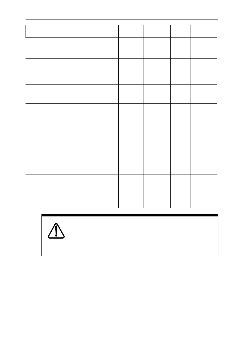
Trunk REN USOC SOC FIC
GATC LSDS (NT7B69AAAA) 0.0 A
0.0 B
Loop Start/Disconnect Supervision
(LS/DS)- NT7B75GA-93
P0603534 02 Modular ICS 6.1 Installer Guide
AC
1.5B
DC 0.3
RJ21X 9.0F 02LS2
RJ21X 9.0F 02LS2
Page 28
28 / North American regulations
Trunk REN USOC SOC FIC
GATC CI (NT7B75AAC) 0.0 A
0.0 B
Call Information (CI)- NT5B41GA-93 AC
1.5B
DC 0.3
DTI (T1 or PRI) - NT7B74AAAA/
A0897902
E&M - NT5B38GA-93 — RJ2HX 9.0F TL32M
BRI-U2 and BRI-U4 Cards
NT7B86GB-93 and
NT7B87GB-93
BRI-ST - NT7B76GY-93
(when connected to an NT1 which
has a U interface to the telephone
network)
DID - NT5B37GA-93 0.0B RJ21X AS.2 02RV2-T
Off-premise sets (OPX) -
Analog Terminal Adapter
— RJ48C 6.0Y 04DU9-
— RJ49C 6.0Y 02IS5
— RJ49C 6.0Y 021S5
— RJ11C 9.0F 0L13B
RJ21X 9.0F 02LS2
RJ21X 9.0F 02LS2
1SN
Notify service provider if DTI is disconnected.
You must notify your T1 service provider any time the
1.544 Mbps DTI interface is disconnected from the
network.
Modular ICS 6.1 Installer Guide P0603534 02
Page 29

North American regulations / 29
In some states, customers are permitted to install their own
jacks.
• The equipment cannot be used with or connected to a party
line or a public coin phone service provided by the
telephone company. Connection to Party Line Service is
subject to state tariffs. Contact the Public State Utility
Commission, Public Service Commission or Corporation
Commission for information.
• It is no longer necessary to notify the Telephone Company
of your system Registration and REN numbers. However,
you must provide this information to the telephone
company if they request it.
• If this equipment causes harm to the telephone network,
the telephone company will notify you in advance that
temporary discontinuance of service may be required. If
advance notice is not practical, the telephone company will
notify the customer as soon as possible. Also, you will be
advised of your right to file a complaint with the FCC if
you believe it necessary.
• The telephone company may make changes in its facilities,
equipment, operations or procedures that could affect the
operation of the equipment. If this happens the telephone
company will provide advance notice in order for you to
make necessary modifications to maintain uninterrupted
service.
• Do not attempt to repair this equipment yourself. If trouble
is experienced with this equipment, please refer to the
repair and warranty information, noted below. If the
equipment is causing harm to the telephone network, the
telephone company may request that you disconnect the
equipment until the problem is resolved.
P0603534 02 Modular ICS 6.1 Installer Guide
Page 30

30 / North American regulations
• Allowing Direct Inward Dial (DID) Equipment to be
operated in such a manner as to not provide for proper
answer supervision is a violation of Part 68 of the FCC
Rules. Proper answer supervision is when:
a. This equipment returns answer supervision to the PSTN
when DID calls are:
— answered by the called station
— answered by the attendant
— routed to a recorded announcement that can be
administered by the CPE user.
— routed to a dial prompt
b. This equipment returns answer supervision on all DID
calls forwarded to the PSTN. Permissible exceptions
are:
— a call is unanswered.
— a busy tone is received.
— a reorder tone is received.
Canada
Before installing this equipment, users should ensure that it is
permissible to be connected to the facilities of the local
telecommunications company. The equipment must also be
installed using an acceptable method of connection. The
customer should be aware that compliance with the above
conditions may not prevent degradation of service in some
situations.
Repairs to certified equipment should be made by an
authorized Canadian maintenance facility designated by the
supplier. Any repairs or alterations made by the user to this
equipment, or equipment malfunctions, may give the
Modular ICS 6.1 Installer Guide P0603534 02
Page 31

North American regulations / 31
telecommunications company cause to request the user to
disconnect the equipment.
Users should ensure for their own protection that the electrical
ground connections of the power utility, telephone lines and
internal metallic water pipe system, if present, are connected
together. This precaution may be particularly important in
rural areas.
Caution
Users should not attempt to make such connections
themselves, but should contact the appropriate electric
inspection authority, or electrician, as appropriate
This Class A digital apparatus meets all requirements of the
Canadian Interference-Causing Equipment Regulations as
specified in the Industry Canada Standard ICES-003.
Signaling method
The equipment allows signaling in DTMF tones. It can
complete calls to local and long distance lines and can also
complete long distance calls via computer phone systems such
as MCI or SPRINT. This equipment is capable of providing
access to interstate providers of operator services through the
use of access codes. Modification of this equipment by call
aggregators to block access dialing codes is a violation of the
Telephone Operator Consumers Act of 1990.
Ringer Equivalence Number
US
The FCC Registration information on the product label,
includes a Ringer Equivalence Number (REN) which is used
to determine the number of devices you may connect to your
P0603534 02 Modular ICS 6.1 Installer Guide
Page 32

32 / North American regulations
phone line. A high total REN may prevent ICSs from detecting
ringing in response to an incoming call and may make placing
calls difficult. In most, but not all areas, the sum of the RENs
should not exceed five (5.0). To be certain of the number of
devices that may be connected to a line, as determined by the
total RENs, contact the local telephone company.
Note: RENs are associated with loop start and ground start ports. Do not
use for E&M or digital ports.
Canada
The Ringer Equivalence Number (REN) assigned to each
terminal device provides an indication of the maximum
number of terminals allowed to be connected to a telephone
interface. The termination on an interface may consist of any
combination of devices subject only to the requirement that
sum of the ringer equivalence numbers of all the devices does
not exceed 5.
Hearing aid compatibility (HAC )
The telephone station sets are compatible with hearing aids
equipped with an appropriate telecoil and is compliant with the
requirements of the Americans with Disabilities Act (ADA).
Use of a music source
In accordance with US, Canadian and international copyright
laws, a license may be required from the American Society of
Composers, Authors and Publishers, or other composers’ or
performing rights organization if Radio, TV or other
broadcasts to the public are transmitted through the Music On
Hold or Background Music features of this telecommunication
system.
Modular ICS 6.1 Installer Guide P0603534 02
Page 33

North American regulations / 33
Programming emergency numbers
When programming emergency numbers and/or making test
calls to emergency numbers:
1. Remain on the line and briefly explain to the dispatcher the reason for
calling before hanging up.
2. Perform such activities in the off-peak hours, such as early mornings
or late evenings.
Substitution of non-approved equipment will void the
NORTEL warranty.
Address for warranty and repairs in the US:
Nortel
640 Massman Drive
Nashville TN 37210
Address for warranty and repairs in Canada:
Nortel
30 Norelco Drive
Weston, Ontario M9L 2X6
For more information call 1-800-4NORTEL.
P0603534 02 Modular ICS 6.1 Installer Guide
Page 34

34 / Limited Warranty
Limited Warranty
Nortel Networks warrants this product against defects and
malfunctions during a one (1) year period from the date of
original purchase. If there is a defect or malfunction, Nortel
Networks shall, at its option, and as the exclusive remedy,
either repair or replace the telephone set at no charge, if
returned within the warranty period.
If replacement parts are used in making repairs, these parts
may be refurbished, or may contain refurbished materials. If it
is necessary to replace the telephone set, it may be replaced
with a refurbished telephone of the same design and color. If it
should become necessary to repair or replace a defective or
malfunctioning telephone set under this warranty, the
provisions of this warranty shall apply to the repaired or
replaced telephone set until the expiration of ninety (90) days
from the date of pick up, or the date of shipment to you, of the
repaired or replacement set, or until the end of the original
warranty period, whichever is later. Proof of the original
purchase date is to be provided with all telephone sets returned
for warranty repairs.
Exclusions
Nortel Networks does not warrant its telephone sets to be
compatible with the equipment of any particular telephone
company. This warranty does not extend to damage to
products resulting from improper installation or operation,
alteration, accident, neglect, abuse, misuse, fire or natural
causes such as storms or floods, after the telephone is in your
possession.
Nortel Networks shall not be liable for any incidental or
consequential damages, including, but not limited to, loss,
damage or expense directly or indirectly arising from the
Modular ICS 6.1 Installer Guide P0603534 02
Page 35

Limited Warranty / 35
customers use of or inability to use this telephone, either
separately or in combination with other equipment. This
paragraph, however, shall not apply to consequential damages
for injury to the person in the case of telephones used or
bought for use primarily for personal, family or household
purposes.
This warranty sets forth the entire liability and obligations of
Nortel Networks with respect to breach of warranty, and the
warranties set forth or limited herein are the sole warranties
and are in lieu of all other warranties, expressed or implied,
including warranties or fitness for particular purpose and
merchantability.
P0603534 02 Modular ICS 6.1 Installer Guide
Page 36

36 / International Regulatory Information
International Regulatory Information
The CE Marking on this equipment indicates
compliance with the following:
This device conforms to Directive 1999/5/EC on
Radio Equipment and Telecommunications
Terminal Equipment as adopted by the European
Parliament And Of The Council.
This is a class A product. In a domestic environment this
product may cause radio interference in which case the user
may be required to take adequate measures.
Information is subject to change without notice. Nortel
Networks reserves the right to make changes in design or
components as progress in engineering and manufacturing
may warrant. This equipment has been tested and found to
comply with the European Safety requirements EN 60950 and
EMC requirements EN 55022 (Class A) and EN 55024. These
EMC limits are designed to provide reasonable protection
against harmful interference when the equipment is operated
in a commercial and light industrial environment.
WARNING
This is a class A product. In a domestic environment this
product may cause radio interference in which case the
user may be required to take adequate measures. The
above warning is inserted for regulatory reasons. If any
customer believes that they have an interference
problem, either because their Nortel Networks product
seems to cause interference or suffers from interference,
they should contact their distributor immediately. The
distributor will assist with a remedy for any problems
and, if necessary, will have full support from Nortel
Networks.
Modular ICS 6.1 Installer Guide P0603534 02
Page 37

How to use this document
This guide provides core installation and programming
information for MICS 6.1 and MICS-XC 6.1 systems. If you
are installing a MICS-XC system, also refer to the Modular
ICS Companion Installer Guide for Companion installation
and programming.
• The MICS system can be a mini (no expansion cartridge
installed), a midi (installed with a two-port expansion
cartridge), a maxi (installed with a six-port expansion
cartridge), or a mega (Combination Fiber six-port Services
Cartridges and Services cartridges) system. For more
information about the configurations, see Connecting
expansion modules on page 234. This version of the
software does not support Companion.
• The MICS-XC system has all the functionality of MICS,
plus it supports the Companion wireless functionality.
Both systems support ISDN PRI and BRI, and T1
functionality. All MICS 6.1 functionality is described in this
book. For system coordinators, the MICS 6.1 System
Coordinator Guide explains how to perform common
telephone programming.
Companion wireless programming and installation
instructions are documented in the Modular ICS Companion
Installer Guide and the Modular ICS Companion System
Coordinator Guide.
Information that is specific to MICS-XC systems or MICS
systems is clearly marked within this guide.
Note: Throughout this guide, reference to KSU refers to
the Integrated Communication System (ICS).
P0603534 02 Modular ICS 6.1 Installer Guide
Page 38

38 / How to use this document
Modular ICS 6.1 Installer Guide P0603534 02
Page 39

What’s new with Norstar
The Norstar MICS 6.1 includes several new features and a few
functionality changes.
To upgrade from any previous version of
MICS software to MICS 6.1, refer to
Upgrading your Norstar system on page 199
for detailed instructions.
New features and hardware for version 6.1
• T24 Key Indicator Module (KIM) and T7316E Business
Series Terminal. When put together, the unit is referred to
as a Central Answer Position (CAP).
These two pieces of hardware are designed to replace the
M7324/CAP module setup. The T7316E can also be
deployed as a stand-alone unit, and works the same way as
previous versions of the T7316 with some minor changes,
including an active handsfree key below the main dialpad.
Both units come with installation instructions.
The KIM can be used in two configurations. The ordinary
KIM (OKIM) has the same functionality as the current
unassigned CAP module. The enhanced KIM (eKIM)
supports lines, multiple target lines, and hunt group
appearances (CAP/KIM assign on page 435).
Up to four KIMs can be attached to an enhanced T7316E,
without requiring a system auxiliary power supply
(SAPS). A T7316E can only support a maximum of four
eKIMs, however, it can support up to nine OKIMs, with
the addition of a SAPS. The system can support a
maximum of five CAP units using EKIMs. This number
P0603534 02 Modular ICS 6.1 Installer Guide
Page 40

40 / What’s new with Norstar
will include any T7324-based CAP installations you might
already have. The system can support many more CAP
units using OKIMS.
The KIM and T7316E also provide call-specific icons to
make call tracking easier.
You cannot program Answer DN keys onto a KIM.
• destination code enhancements
— 12-digit destination code: You can specify up to 12
digits as a destination code, which allows you to
support user expectations of dialing requirements for
existing systems. For instance, if your users are used to
dialing 91XXX-XXX-XXXX for a long distant call,
they can continue to do so, even though the call may go
through your private network or may use more than
one route. This allows you to provide a seamless
transition to network dialing. (Routes and destination
codes on page 381)
— multiple least-cost routing: When you specify a
schedule other than Normal for a destination code, you
can specify up to three possible routes the call can
access, in order of preference. (Programming for least
cost routing on page 395)
• Silent monitor for hunt groups
Your Hunt group supervisors can now monitor hunt group
calls, either silently, or by providing a conference tone to
indicate that the call is being monitored (Silent Monitor on
page 432). Other new functionality has been added to
allow you to determine which telephones will be allowed
to silent monitor (Capabilities on page 335), how many
monitoring telephones your system will allow (SM sets on
page 466), and what password is required to enter a
monitoring session (Silent Monitor password on page
407). Refer to the Modular ICS 6.1 System Coordinator
Modular ICS 6.1 Installer Guide P0603534 02
Page 41

What’s new with Norstar / 41
Guide for a detailed description about how to use the
feature.
• CLID display enhancements:
— display an incoming call CLID on a telephone with
activated CLID display, where a call is currently
active.
• overlap dialing (profile 2 only)
— For calls over PRI lines that require pauses between
dialing sequences, this feature allows the line to send a
dialtone to the user between dialing an access code and
dialing the telephone number.
Other feature notes
• MCDN Meridian attendant break-in feature correction:
Only post-dial break-in is allowed. (Break-in on page 154)
• MCDN Meridian attendant camp-on feature note:
Meridian attendants need to be notified that they must wait
at least five seconds before assuming that a camp-on call
has been camped. This is due to remote system
requirements for checking for busy on the target telephone
and determining if a prime telephone has been assigned.
• MCDN on tandem networks has been adjusted to correct
or accommodate some networking issues experienced in
previous versions. Changes are invisible to the user.
The Norstar Remote Utility (NRU) application is being
replaced by the ICS Remote Tools (ICSRT) application, which
has some of the same functionality of Norstar Manager. The
ICSRT Quick Reference Guide provides an overview of the
features of the ICSRT application. The ICS Remote Tools User
Guide provides details about using the application.
P0603534 02 Modular ICS 6.1 Installer Guide
Page 42

42 / What’s new with Norstar
Modular ICS 6.1 Installer Guide P0603534 02
Page 43

Welcome to ISDN
This chapter provides you with some background information
about ISDN, including information about:
• analog vs. ISDN
• type of ISDN service
• ISDN layers
• ISDN bearer capability
• services and features for ISDN PRI and BRI
• ISDN hardware
• ISDN standards compatibility
Integrated Services Digital Network (ISDN) technology
provides a fast, accurate, and reliable means of sending and
receiving voice, data, images, text, and other information
through the telecom network.
ISDN uses existing analog telephone wires. The signal on the
wire gets divided into separate digital channels, which
dramatically increases the bandwidth.
ISDN uses a single transport to carry multiple information
types. What once required separate networks for voice, data,
images, or video conferencing is now combined on to one
common high-speed transport.
Note: Nortel endeavors to test all variations of ISDN BRI and
PRI on Norstar. However, due to the number of
variations, this is not always possible. Check with your
service provider about compatibility.
P0603534 02 Modular ICS 6.1 Installer Guide
Page 44

44 / Welcome to ISDN
Comparing ISDN to Analog
ISDN offers significantly higher bandwidth and speed than
analog transmission because of its end-to-end digital
connectivity on all transmission circuits. Being digital allows
ISDN lines to provide better quality signaling than analog
POTS (plain ordinary telephone) lines. Also ISDN out-ofband data channel signaling offers faster call setup and tear
down.
While an analog line carries only a single transmission at a
time, an ISDN line can carry one or more voice, data, fax and
video transmissions simultaneously.
An analog modem operating at 14.4 K takes about 4.5 minutes
to transfer a 1 MB data file, while a 28.8K modem takes about
half that time. Using one channel of an ISDN line, the transfer
time is reduced to only one minute. If two ISDN channels are
used, transfer time is just 30 seconds.
When transmitting data, the connect time for an average ISDN
call is about three seconds per call, compared to about 21
seconds for the average analog modem call.
Type of ISDN service
Two types of ISDN services (lines) are available: Basic Rate
Interface (BRI) and Primary Rate Interface (PRI). Each line is
made up of separate channels known as B and D channels
which transmit information simultaneously.
• BRI is known as 2B+D because it consists of
2 B-channels and one D-channel.
• PRI is known as 23B+D because it consists of
23 B-channels and one D-channel.
Modular ICS 6.1 Installer Guide P0603534 02
Page 45

Welcome to ISDN / 45
B channels
B channels are the bearer channel. They are used to carry voice
or data information and have speeds of 64 kbps. Since each
ISDN line (BRI or PRI) has more than one B-channel, more
than one transmission can occur at the same time, using a
single ISDN line.
D channels
The standard signaling protocol is transmitted over a dedicated
data channel called the D-channel. The D-channel carries call
setup and feature activation information to the destination.
This channel has speeds of 16 kbps (BRI) and 64 kbps (PRI).
Data information consists of control and signal information
and packet-switched data such as credit card verification.
Tip -
channel only. Norstar does not include support for a
backup D-channel on the span.
Norstar PRI supports the D-channel on the 24th
ISDN layers
ISDN layers refer to the standards established to guide the
manufacturers of ISDN equipment. The layers include both
physical connections, such as wiring, and logical connections,
which are programmed in computer software.
When equipment is designed to the ISDN standard for one of
the layers, it works with equipment for the layers above and
below it.
There are three layers at work in ISDN for Norstar. To support
ISDN service, all three layers must be working properly.
P0603534 02 Modular ICS 6.1 Installer Guide
Page 46

46 / Welcome to ISDN
Layer 1: A physical connection that supports fundamental
signaling passed between the ISDN network (your service
provider) and the Norstar ICS. When a DTI card configured as
BRI or PRI is used for a network connection, the LED for the
loop on the card is lit when the layer 1 is functioning.
Layer 2: A logical connection between the ISDN network
(your service provider) and the Norstar ICS. Norstar has two
of these connections for each BRI line, one for each of the
logical lines. Without Layer 2, call processing is not possible,
and there is no dial tone.
Layer 3: Also a logical connection between the ISDN network
(your service provider) and the Norstar ICS. For BRI lines,
layer 3 is where call processing and service profile identifier
(SPID) information is exchanged. This controls which central
office services are available to the connection. For example, a
network connection can be programmed to carry data calls.
The system of layers is important when you are installing,
maintaining, and troubleshooting an ISDN system. See
Problems with BRI service on page 600 for more information
about working with the layers.
ISDN bearer capability
Bearer capability describes the transmission standard used by
the BRI or PRI line that allows it to work within a larger ISDN
hardware and software network.
The bearer capability for BRI and PRI is voice/speech at
3.1 kHz audio, and data at unrestricted 64 kbps, restricted
64 kbps, 56 kbps.
Modular ICS 6.1 Installer Guide P0603534 02
Page 47

Welcome to ISDN / 47
Services and features for ISDN PRI and BRI
As part of an ISDN digital network, your Modular ICS
supports enhanced capabilities and features, including:
• faster call setup and tear down
• high quality voice transmission
• dial-up Internet and local area network (LAN) access
• video transmission
• network name display
• name and number blocking (PRI, BRI and analog)
• access to public protocols (only NI-1 for BRI)
PRI services and features
• call by call service selection
• dialing plan
• Emergency 911 dialing, internal extension number
transmission
• Advanced Private Networking to Meridian 1 using SL-1
protocol, providing
– access to central Voice Mail and Automated Attendant
equipment connected to the Meridian system
– Message Waiting Indication (MWI) from the Voice
Mail application
– Network Call Redirection Information (NCRI), which
is built on the existing Call Forward and Call Transfer
features
– trunk route optimization (TRO)
– trunk anti-tromboning (TAT)
– ISDN call connection limitation (ICCL)
• tandem networking between Norstar systems
P0603534 02 Modular ICS 6.1 Installer Guide
Page 48

48 / Welcome to ISDN
BRI services and features
• data transmission at speeds up to 128 kbps per loop,
depending on the bandwidth supported by your service
provider
• shared digital lines for voice and data ISDN terminal
equipment
Norstar Basic Rate Interface (BRI) cards also support
D-channel packet service between a network and terminal
connection. This allows you to add applications such as pointof-sale terminals without additional network connections.
Any analog or digital network connections can be shared by all
Norstar telephones, peripherals and applications, and ISDN
terminal equipment (TE).
Modular ICS supports the following ISDN services and
features offered by ISDN service providers:
• D-channel packet service (BRI only) to support devices
such as transaction terminals. Transaction terminals are
used to swipe credit or debit cards and transmit the
information to a financial institution in data packets.
• calling number identification, which appears on both
Norstar sets and ISDN terminal equipment with the
capability to show the information
• Multi-Line Hunt or DN Hunting which switches a call to
another ISDN line if the line usually used by the Network
DN is busy. (BRI only)
• subaddressing of terminal equipment (TE) on the same
BRI loop. However, terminal equipment which supports
sub-addressing is not commonly available in North
America. (BRI only)
Modular ICS 6.1 Installer Guide P0603534 02
Page 49

Welcome to ISDN / 49
Transmission of B-channel packet data is not supported by
Modular ICS.
Contact your ISDN service provider for more information
about these services and features. Packages for ISDN service
in North America are described on page 64.
The terminal equipment (TE) connected to the Norstar system
can use some feature codes supported by the ISDN service
provider. Refer to ISDN services and features in the Modular
ICS 6.1 System Coordinator Guide for more information.
Feature descriptions
The following section provides brief descriptions about the
ISDN features, and links for more programming information.
Network name display
This feature allows ISDN to deliver the Name information of
the users to those who are involved in a call that is on a public
or private network. For information about system
programming for this feature see, BusName on page 453.
Systems with Advanced Private Networking connections
(MCDN SL-1) to a Meridian system also retain information
about sets that have forwarded or transferred a call, as well as
the originating caller information.This feature is called
Network Call Redirection Information (NCRI). This
information is available to all parties involved in the call.
Calls can only be redirected for a defined number of times
within the network. This is currently hardcoded to five times.
Once this limit is reached, call redirection will be disallowed
for any type of outgoing line being presented for redirection.
P0603534 02 Modular ICS 6.1 Installer Guide
Page 50

50 / Welcome to ISDN
Instead, the call will be handled in one of these ways:
• If Call Forward on Busy is programmed, the call will ring
if a free key is available. Otherwise, it goes to the Prime
set. DND Busy programming is ignored.
• If Call Forward All Calls is programmed, the call will go
to the Prime set.
• If Call Forward No Answer is programmed, the call will
continue to ring at the destination.
Note: If a terminal rejects a call, the call goes to the Prime set,
if a Prime set is configured for the target line. If the
target line is configured to send a busy tone, the call
gets released with the reason as User Busy.
Message Waiting Indicator (MWI)
Systems with Advanced Private Networking connections to a
Meridian system Voice Mail system provide message-waiting
indicators at telephones connected to those lines. Telephones
with displays display a message. Non-display terminals may
have a lamp that lights when a message is waiting. The setting
for this feature is defined from the Meridian system.
Name and number blocking
This feature suppresses the outgoing name and/or number on
a call-by-call basis. For information on system programming
of this feature see, Outgoing Name and Number Blocking on
page 456.
External call forwarding
The system now allows you to forward calls to an external
number. This feature is activated using ≤› from the
telephone.
Modular ICS 6.1 Installer Guide P0603534 02
Page 51

Welcome to ISDN / 51
MCDN trunk features
Systems with MCDN Private Networking connections can
provide these trunk routing features:
• Trunk Route Optimization (TRO) finds the most direct
route through the network to send a call between nodes.
This function occurs during the initial alerting phase of a
call.
• ISDN Call Connection Limitation: The ICCL feature
piggybacks on the call initiation request and acts as a check
at transit PBX points to prevent misconfigured routes or
calls with errors from blocking channels.
• Trunk Anti-tromboning (TAT) is a call-reroute feature that
works to find better routes during a transfer of an active
call. This feature acts to prevent unnecessary tromboning
of trunks. This action occurs after the speech path has been
established.
Call by Call service selection for PRI
Call by Call service selection allows a user to access services
or private facilities over a PRI line without the use of dedicated
facilities. Various types of services such as FX, Tie, and
OUTWATS are available, depending on the Protocol that is
selected. Private network settings are used for tandem
networking and Advanced Private Networking.
Outgoing calls are routed through a dedicated PRI Pool and the
calls can be routed based on various schedules.
For information about system programming of this feature, see
Programming Call by Call service selection on page 460.
P0603534 02 Modular ICS 6.1 Installer Guide
Page 52

52 / Welcome to ISDN
For services information about dialing plans and PRI, see
Networking with Norstar on page 99 and Dialing Plan on page
436.
Refer to the hardware section for Call-by-call routing on page
485.
Emergency 911 dialing
Modular ICS 6.1 with the ISDN PRI feature is capable of
transmitting the telephone number and internal extension
number of a calling station dialing 911 to the Public Switched
Telephone Network.
State and local requirements for support of Emergency 911
dialing service by Customer Premises Equipment vary.
Consult your local telecommunications service provider
regarding compliance with applicable laws and regulations.
For most installations, the following configuration rules
should be followed, unless local regulations require other
settings.
• All PSTN connections must be over PRI.
• In order for all sets to be reachable from the Public Safety
Answering Point (PSAP), the system must be configured
for DID access to all sets. In order to reduce confusion, the
dial digits for each telephone should be configured to
correspond to the extension number (DN).
• The OLI digits for each telephone should be identical to
the DID dialed digits for the telephone.
• The System Coordinator is responsible for maintaining a
site map or location directory that allows emergency
personnel to rapidly locate a telephone given its DID
number. This list should be kept up to date and readily
available, and can be included in the Programming Record
Modular ICS 6.1 Installer Guide P0603534 02
Page 53

Welcome to ISDN / 53
• The routing table should route 911 to a public line or line
pool.
• If attendant notification is required, the routing table must
be set up for all 911 calls to use a dedicated line which has
an appearance on the attendant console.
Note: The actual digit string 911 is not hard-coded into the
system. More than one emergency number can be
supported
MCID (Profile 2)
The MCID feature allows you to use ≤°·‡ to have
call information recorded on the central office database for an
incoming call on a specific line (EUROISDN lines, only).
The user must invoke the feature code during the active call or
within 30 seconds (time varies on different networks) after the
caller hangs up. The user must remain on the line to enter the
code.
Network Call Diversion (Profile 2)
This feature is a network function of ETSI E1 lines that allows
forwarding and redirection of calls outside the Norstar
network when using an ETSI ISDN line. Functionality is
similar to that of External Call Forward (ECF). NCD redirects
calls using the same line on which they arrive. Call forward is
efficient since there is no need for additional outside lines.
DTI card configured as a PRI card
The DTI card on your Norstar system can be configured to
support PRI. For information about configuring a DTI card as
a PRI type card, see Provisioning the DTI card for PRI on page
483.
P0603534 02 Modular ICS 6.1 Installer Guide
Page 54

54 / Welcome to ISDN
ISDN hardware
To support connections to an ISDN network and ISDN
terminal equipment, your Modular ICS must be equipped with
one or more BRI cards (BRI-U or BRI-ST), a DTI card
configured for PRI, and a Combination Fiber 6-port Services
Cartridge or a Services Cartridge.
DTI card configured as PRI
A DTI card configured as PRI provides one T loop. Refer to
T reference points on page 58 for more information.
In most PRI network configurations, you need one DTI card
configured as PRI in your ICS to act as the primary clock
reference. The only time when you may not have PRI
designated as the primary clock reference is in a network
where your Norstar system is connected back-to-back with
another switch using a PRI link, such as is the case with the
Advanced Private Networking configuration.
However, if the other switch is loop-timed to your Norstar
system, your DTI card, configured as PRI, can be designated
as a timing master.
If your Norstar has two DTI cards configured as PRI, you
cannot assign both cards as the primary reference or both cards
as the secondary reference. You can only have one primary
reference and one secondary reference per system. Refer to
ClockSrc on page 492 for more information.
BRI Card
The loops on BRI-U and BRI-ST cards can be programmed to
support either network or terminal connections. This allows
you to customize your arrangement of lines, voice terminals,
data terminals and other ISDN equipment.
Modular ICS 6.1 Installer Guide P0603534 02
Page 55

Welcome to ISDN / 55
Detailed wiring information for BRI and PRI network and
terminal connections is included in the Installation on page
219.
BRI-U2 and BRI-U4 card
A BRI-U2 card supports two loops and the BRI-U4 supports
four loops. Each loop can be individually programmed to
provide one of the following:
• a U-LT reference point connection for terminal equipment
(TE) with built-in NT1 functionality (U interface)
• a U-NT reference point connection for direct connection to
an ISDN network
BRI-ST card
A BRI-ST card provides four loops. Each loop can be
individually programmed to one of the following:
• an S reference point connection (S loop) to ISDN terminal
equipment (TE)
• a T or S reference point connection (T loop or S loop) to an
ISDN network using an external NT1
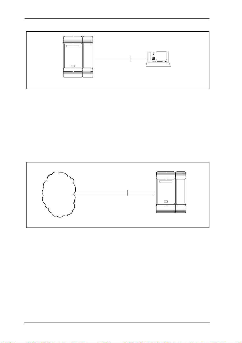
U-LT reference point
The U-LT reference point connection provides a point-topoint digital connection between Norstar and TE equipped
with a U interface.
A U-LT loop supports up to eight ISDN DNs, which identify
TE to the ICS. Refer to the example below.
P0603534 02 Modular ICS 6.1 Installer Guide
Page 56
56 / Welcome to ISDN
point-to-point
U-LT
U interface TE
ICS
U-NT reference points
The U-NT reference point connection provides a point-topoint digital connection between the ISDN network and the
ICS.
A U-NT loop provides lines that can be used by all Norstar
telephones, peripherals and applications, and ISDN TE.
network
connection
ISDN
U-NT
ICS
U-NT and U-LT loops can be used in combination to provide
D-packet service for a point-of-sale terminal adapter (POSTA)
or other D-packet device. D-packet service is a 16 kbps data
transmission service that uses the D-channel of an ISDN line.
To deliver D-packet service, a network connection (U-NT) is
programmed to work with a terminal connection (U-LT). The
loops must be on the same physical card. For example, if the
network connection is a loop found on the BRI Card in Slot 1,
the terminal connection must be a loop found on the same card.
Modular ICS 6.1 Installer Guide P0603534 02
Page 57

Welcome to ISDN / 57
Inspect FORWARD Callers
MXP
Inspect FORWARD Callers
MXP
Inspect FORWARD Callers
MXP
S reference point
The S reference point connection provides either a point-topoint or point-to-multipoint digital connection between
Norstar and ISDN terminal equipment (TE) that uses an
S interface.
S loops support up to seven ISDN DNs, which identify TE to
the ICS.
ISDN TE
point-to-point
S
(with terminating resistors)
In
s
p
e
c
t F
O
R
W
A
R
D
C
a
lle
rs
M
X
P
ISDN TE
In
s
p
e
c
t
F
O
R
W
A
R
D
C
a
ll
e
rs
M
X
P
ICS
P0603534 02 Modular ICS 6.1 Installer Guide
S
In
s
p
e
c
t F
O
R
W
A
R
D
C
a
lle
rs
M
X
P
ISDN TE
ISDN TE
(with terminating
resistors)
Page 58

58 / Welcome to ISDN
T reference points
The T reference point connections provide a point-to-point
digital connection between the ISDN network and Norstar.
A T loop provides lines that can be shared by all Norstar
telephones, peripherals and applications, and ISDN TE.
network
ISDN
connection
T
ICS
A T loop can be used in combination with an S loop to provide
D-packet service for a point-of-sale terminal adapter (POSTA)
or other D-packet device. D-packet service is a 16 kbps data
transmission service that uses the D-channel of an ISDN line.
To deliver D-packet service, a network connection (T loop) is
programmed to work with a terminal connection (S loop). The
loops must be on the same physical card. For example, if the
network connection is a loop found on the BRI Card in Slot 1,
the terminal connection must be a loop found on the same card
Modular ICS 6.1 Installer Guide P0603534 02
Page 59

Welcome to ISDN / 59
Clock source for ISDN cards
Systems with ISDN interfaces need to synchronize clocking
with the ISDN network and any connected ISDN terminal
equipment. Clocking synchronization is supported by either a
Combination Fiber 6-port Services Cartridge or a Services
Cartridge.
The Modular ICS derives timing from the network using
U-NT and T reference points (loops). Terminal equipment on
U-LT and S reference points (loops) derive timing from the
ICS.
Systems synchronize clocking to the first-available functional
network connection. If there are excessive errors on the
reference network connection, or if the loop fails, the nextavailable functional network connection is used for clock
synchronization.
The clock synchronization process generates alarm codes and
event messages. See the Alarm codes on page 533 and Event
messages on page 541 for more information.
When you configure the network connections to the Modular
ICS, you should take into account the system preferences for
selecting loops for synchronization:
• lower numbered loops have preference over higher
numbered loops
• the loop preference order is: 201, 202, 203, 204, 225, 226,
227, 228 (Profile 1, 3 and 4), or 201, 202, 203, 204, 231,
232, 233, 234 (Profile 2)
• the system skips U-LT, S, and analog loops when selecting
a network connection for synchronization
P0603534 02 Modular ICS 6.1 Installer Guide
Page 60

60 / Welcome to ISDN
Systems with only U-LT and S loops act as timing masters for
the attached terminal equipment (TE), and are not
synchronized to the network. ISDN TE without access to a
network connection (BRI lines) has limited or no
functionality.
If your system has both a BRI and a DTI card configured as
PRI installed, it is recommended that you use PRI as the
primary clock source, see DTI card configured as a PRI card
on page 53.
Other ISDN BRI equipment: NT1
The NT1 (network termination type 1) connects an S interface
(four-wire) to a U interface (two-wire). In most cases, it
connects loops from a BRI-ST card to the network connection,
which uses the U interface. It can also connect S interface
terminal equipment (TE) to the U loop from a BRI-U2 or
BRI-U4 Card.
An NT1 is not required to connect from the network to BRI-U
cards or to connect U interface TE to an ICS equipped with
BRI-U cards.
The NT1 converts and reformats data so it can be transmitted
to and from the S or T connection. In addition, it manages the
maintenance messages travelling between the network and the
NT1, and between the NT1 and the ICS.
The NT1 from Nortel Networks is packaged two ways:
• as a stand alone package, which contains one NT1 card
(NTBX80XX) and a power supply (NTBX81XX)
• as a modular package, which contains up to 12 NT1 cards
(NTBX83XX) and a power supply (NTBX86AA)
Modular ICS 6.1 Installer Guide P0603534 02
Page 61

Welcome to ISDN / 61
ISDN standards compatibility
Norstar ISDN equipment supports National ISDN standards
for basic call and calling line identification services.
Norstar BRI is compliant with National-1 and PRI is
compliant with National-2.
Modular ICS does not support EKTS (Electronic Key
Telephone System) or CACH (Call Appearance Call
Handling).
P0603534 02 Modular ICS 6.1 Installer Guide
Page 62

62 / Welcome to ISDN
Modular ICS 6.1 Installer Guide P0603534 02
Page 63

Working with ISDN
Planning your ISDN network
Consult ISDN hardware on page 54 and ISDN programming
on page 66 to determine a configuration of ISDN trunks and
terminal equipment (TE) for the Modular ICS, then order the
appropriate ISDN capability package from your ISDN service
provider.
For ISDN BRI service, your service provider supplies service
profile identifiers (SPIDs), network directory numbers
(Network DNs), terminal endpoint identifiers (TEIs), and
other information, as required, to program your Modular ICS,
TE, and other ISDN equipment.
Modular ICS does not support any package with EKTS
(Electronic Key Telephone System) or CACH (Call
Appearance Call Handling). EKTS is a package of features
provided by the service provider and may include features
such as Call Forwarding, Link, Three-Way Calling, and
Calling Party Identification.
Ordering ISDN PRI
When you order ISDN PRI, order two-way DID because it
simplifies provisioning and provides efficient use of the PRI
bandwidth.
Ordering ISDN PRI service in Canada
In Canada, order Megalink™ service, the trade name for
standard PRI service and set the Norstar equipment to the
supported protocol that is identified by your service provider,
either DMS-100 or NI-2.
P0603534 02 Modular ICS 6.1 Installer Guide
Page 64

64 / Working with ISDN
Ordering ISDN PRI service in United States
In the United States order PRI service from your service
provider. Set the Norstar equipment to the PRI protocol
provided by your service provider.
Ordering ISDN BRI
Ordering service in Canada
In Canada, order Microlink™ service, the trade name for
standard BRI service. You can order either regular
Microlink™ service, which includes the CLID (Calling Line
Identification) feature, or Centrex Microlink™, which
includes access to additional ISDN network features
(including Call Forwarding).
When ordering Microlink™ service, it must be ordered with
EKTS (Electronic Key Telephone System) turned off. If you
will be using a point-of-sale terminal adapter (POSTA), ask
for D-packet service to be enabled.
Ordering ISDN service in the U.S.
In the U.S., regardless of the CO (Central Office) type, order
National ISDN BRI-NI-1 with EKTS (Electronic Key
Telephone System) turned off. Use the following packages as
a guideline for ordering your National ISDN BRI-NI-1.
However we recommend using packages M or P with the
Modular ICS. Contact your service provider for more
information about the capability packages it offers.
Modular ICS 6.1 Installer Guide P0603534 02
Page 65

Working with ISDN / 65
Bellcore/National ISDN Users Forum (NI UF) ISDN packag es
supported by Modular ICS (for ordering in U.S.)
Capability Feature set Optional
M Alternate
voice/circuitswitched data
on both
B-channels
P Alternate
voice/circuitswitched data
on both
B-channels
D-channel
packet
-- calling line
flexible
calling for
voice (not
supported by
Modular ICS)
Basic
D-Channel
Packet
features
identification
additional
call offering
(not
supported by
Modular ICS)
calling line
identification
Point-
sale
--
Voice Data
of-
√ √
√ √ √
If you want to transmit both voice and data, and support
D-channel packet service, order package P. However,
Modular ICS does not support the flexible calling for voice
and additional call offering features that are included in
package P.
Multi-Line Hunt may be ordered with your package. When a
telephone number (the Network DN) in the group of numbers
assigned by your service providers is busy, the Multi-Line
Hunt feature connects the call to another telephone number in
the group. Norstar supports the feature only on point-to-point,
network connections (T loop or U-NT loop). Check with your
service provider for more information about Multi-Line Hunt.
Any of the ISDN packages will allow you to use subaddressing, but your ISDN TE must be equipped to use subaddressing for the feature to work.
P0603534 02 Modular ICS 6.1 Installer Guide
Page 66

66 / Working with ISDN
Supported ISDN protocols
The switch used by your service provider must be running the
appropriate protocol software and the correct version of that
software to support ISDN PRI and ISDN BRI. Each protocol
is different and supports different services. Contact your
service provider to ensure that your ISDN connection has the
protocol you require.
For more information about the supported protocols and
services, refer to Call by Call service selection for PRI on page
457.
ISDN programming
Most of the configuration programming for PRI and BRI lines
and ISDN terminals and devices is done under Hardware.
This section gives you an overview of programming for PRI
and BRI lines, ISDN terminals and devices, and D-packet
service.
PRI or BRI programming activity Programming
heading
View or change the card configuration for each slot
in the ICS
Provision or deprovision loops and lines Provisioning
Enable or disable BRI or DTI card (PRI) Module status
View status of line, loop or port Port/DN status
Enable/disable individual PRI channels Link Status
Modular ICS 6.1 Installer Guide P0603534 02
Hardware
Page 67

Working with ISDN / 67
Programming ISDN PRI resources
Some steps will not be necessary, depending on the service
you are providing.
More detailed information is included under the individual
headings and settings in the Programming and Maintenance
sections.
For complete card and cartridge installation instructions and
safety precautions, see Installation on page 219.
1. Collect the information supplied by your service provider
to support your ISDN package.
2. Ensure that a Combination Fiber 6-port Services
Cartridge, or a Services Cartridge has been installed in the
ICS.
3. Install the DTI cards in the ICS. Refer to Installing the
cartridges on page 223 for information about card
placement. If you are not using DTI cards, determine
which type of card you will preprogram the ICS to use in
each slot.
Tips -
card can be installed off-core on Module 3 or 4 on the Midi
system, or module 7 or 8 on the Maxi system to expand the PRI
capability of your system. This card is only supported on
Profile 1 and 4.
Note: Legacy DTI cards cannot be used off-core. A new DTI
card was released in 2002 that can be used in any position.
For systems running 6.0 or greater software, a DTI
4. Disable each card under Maintenance.
P0603534 02 Modular ICS 6.1 Installer Guide
Page 68

68 / Working with ISDN
5. Select a card type (PRI) in Hardware. See Provisioning
the DTI card for PRI on page 483, for information about
protocol and other settings you must configure.
Tips -
for MCDN private networking, this is where you specify that
protocol (SL-1).
If you are using one or more of the lines on this card
6. Re-enable the card in Maintenance.
If required, the card goes through a firmware download
process, which takes five to six minutes. During a
firmware download, the bottom LED on the DTI card
flashes.
Programming ISDN BRI resources
Some steps will not be necessary depending on the service you
are providing.
More detailed information is included under the individual
headings and settings in the Programming and Maintenance
sections.
For complete card and cartridge installation instructions and
safety precautions, see Installation on page 219.
1. Collect the information supplied by your service provider
to support your ISDN package. This includes network
service profile identifiers (SPIDs) and Network DNs. If
you are supporting a point-of-sale terminal adapter, you
also need one or more terminal endpoint identifiers (TEIs).
2. Make sure a Combination Fiber 6-port Services Cartridge,
or a Services Cartridge has been installed in the ICS.
3. Install the BRI card in the ICS, Trunk Module. Refer to
Installing the cartridges on page 223 for information about
Modular ICS 6.1 Installer Guide P0603534 02
Page 69

Working with ISDN / 69
BRI card placement. If you are not using a BRI card,
determine which type of card you will preprogram the ICS
to use in each slot.
4. Disable each card in Maintenance under Module
Status.
5. Under Hardware, select a card type: BRI-ST, BRI-U2,
BRI-U4.
6. Under Hardware, select the type for each loop:
• for a BRI card, select T or S if the card type is BRI-ST
• for a BRI-U2 or BRI-U4 card, select LT or NT
7. If the card uses a T or NT loop, enter the following
information, as supplied by your service provider:
• the SPID assigned to the loop
• the number of B-channels associated with each SPID
• the Network DNs used with the network SPID
• the call type of the Network DN
Repeat the programming for the second network SPID, if
any.
If the T or NT loop is used for D-packet service:
• turn on the service
• assign the appropriate S-loop mapping for BRI-ST
cards or LT-loop mapping for BRI-U2 or U4 cards
• assign the TEIs to the loop. These are provided by the
telco to support a point-of-sale terminal adapter or
other D-packet service device.
If the loop type is S, select the sampling used on the loop.
P0603534 02 Modular ICS 6.1 Installer Guide
Page 70

70 / Working with ISDN
If the loop type is S or LT:
• assign ISDN DNs to the loop
• designate one of the assigned ISDN DNs to be the DN
for the loop (Loop DN).
Note: You can have a maximum of 30 ISDN DNs on your
system. The default ISDN DN range is 667–696 for a
system with three-digit DNs. To change ISDN DN
type, see Change DNs on page 418.
8. Re-enable the card in Maintenance. Refer to Disabling a
PRI Channel on page 551.
If required, the card goes through a firmware download
process, which takes five to six minutes. During a
firmware download, the bottom LED on the BRI card
flashes.
9. Provision the loops and lines, as appropriate, in
Maintenance. Refer to Provisioning BRI and PRI lines on
page 549.
10. If you are configuring auto-answer BRI trunks to map to
target lines, program the received number for the target
line to be the same as the Network DN supplied by your
service provider. This setting is found under Lines.
Assign the ISDN lines and target lines to the appropriate
ISDN DNs, which are the set of DNs reserved for use by
ISDN devices. This setting is found under
Terminals&Sets/Line access. ISDN lines can also be
assigned to the DNs used by the telephones or any other
devices connected to the Modular ICS.
Program the ISDN terminals and devices with the
appropriate ISDN DNs and terminal SPIDs by following
the instructions that come with the devices. For more
information, see Programming ISDN equipment on page
73.
Modular ICS 6.1 Installer Guide P0603534 02
Page 71

Working with ISDN / 71
If you are setting up a D-packet service, program the pointof-sale terminal adapter or other D-packet service device
with the appropriate TEI (provided by your service
provider), terminal SPID, and DN by following the
instructions that come with the device.
Programming ISDN PRI lines
When the configuration programming under Hardware is
complete, your PRI lines are ready to be programmed. For
information about programming your PRI lines, see Call by
Call service selection for PRI on page 457.
Programming ISDN BRI lines
When the configuration programming under Hardware is
complete, your BRI lines are ready to be programmed in the
same way as analog lines. You can, for example, place them in
pools and assign them to Norstar telephones, Business Series
Terminals, or ISDN terminal equipment.
However, there are some differences in the way BRI lines
work that will influence how you configure them to handle
incoming and outgoing calls.
• For BRI lines, in most cases, your service provider
supplies two SPIDs – one for each B channel. Each SPID
and one or more Network DNs are associated with a single
line. Calls to a Network DN come in on a specific line.
Pressing a line button selects the same line every time.
• If your service provider supplies you with a single SPID
for both B channels, incoming and outgoing calls are
handled according to the loop. The two lines provided by
the BRI loop are pooled for both incoming and outgoing
calls.
P0603534 02 Modular ICS 6.1 Installer Guide
Page 72

72 / Working with ISDN
For example, if Loop 201 is programmed with a single
SPID, which supports lines 001 and 002, incoming calls
made to a Network DN associated with the SPID appear on
either line 001 or line 002. If you press the line button for
line 001, either line 001 or line 002 is selected. For loops
which use a single SPID, assign both lines on a loop to a
telephone to guarantee that all calls appear at the
telephone.
Programming Direct Inward System Acce ss (DIS A) on PRI trunks
When a trunk cartridge is set to PRI, all lines on that trunk are
set to Auto Answer without Direct Inward System Access
(DISA).
DISA can be accessed by one of two methods.
1) Define the DISA DN to match the trailing digits of the
Called Party Number (CDN).
With Public, Private, and Tie service types, the CDN is
simply truncated to the Target Line Receive Digit Length
and is parsed to match the Target Line Receive Digits.
DISA can be accessed by having the DISA DN match the
trailing digits of the CDN. For example, with a Receive
Digit Length = 4, and DISA DN = 1234, a call made to
Public DN 763-1234 will be handled as follows:
• the ISDN setup message will contain a CDN of 763-1234
• the CDN will be truncated to the four digits, 1234
• 1234 matches the DISA DN
• the call will be answered with DISA
2) Use incoming Call by Call (CbC) Service routing to map the
call type to the DISA DN. Refer to Programming Call by
Call service selection on page 460 for more information.
Modular ICS 6.1 Installer Guide P0603534 02
Page 73

Working with ISDN / 73
With FX, INWATS, 900, and SDS service types, either a
Service Id (SID) or a CDN is mapped to Target Line
Receive Digits.
This is programmed under Call-by-Call Routing. DISA
may be accessed by having the SID or CDN map to the
DISA DN. This example has a Receive Digit Length = 4,
DISA DN = 1234, and CbC Routing with (Service Type =
FX, Map from SID = 2, Map to digits = 1234).
A call presented to the Norstar system with service type
FX and SID 2 will be handled as follows:
• The ISDN setup message will specify FX with SID = 2
• The FX SID = 2 will be mapped to DISA DN digits 1234
The call will be answered with DISA
Programming ISDN equipment
DTI cards configured as PRI support various applications that
are enabled by PRI. For a list of the type of applications that
are support, see ISDN applications on page 183.
Terminal equipment for BRI cards
ISDN devices and terminals connected to the ICS must be
configured under the Hardware heading in system
programming. You choose directory numbers for ISDN
equipment from a pre-determined range of DNs (667-696).
Any of the ISDN DNs can be assigned to any U-LT or S loop,
but each can only be assigned to one loop and one device.
Devices on an S or LT loop (BRI cards only)
Terminal equipment using a U-LT loop or S loop must be
assigned an ISDN directory number (ISDN DN). This allows
the TE to be assigned lines and to communicate with other
devices connected to the ICS. Each DN can be assigned to only
one TE and one loop.
P0603534 02 Modular ICS 6.1 Installer Guide
Page 74

74 / Working with ISDN
You assign ISDN DNs to S loops and LT loops under Assign
DNs under Hardware. Each S or LT loop can be programmed
with eight ISDN DNs, but you cannot exceed a total of 30
ISDN DNs for the Modular ICS.
Once you have assigned ISDN DNs to a loop, designate one of
the DNs as a Loop DN. The Loop DN acts as a main ISDN DN
and completes the configuration of the loop.
The ISDN terminal equipment (TE) on the loop is also
programmed with its ISDN DN. See the instructions that come
with the ISDN device for information on how to program it to
recognize the assigned DN. Most devices will require both a
terminal service profile identifier (terminal SPID) and a DN,
and some will require two terminal SPIDs and two ISDN DNs.
The SPID used with the device should not be confused with a
SPID used for network connections using an T or NT loop.
To create a terminal SPID for a device, add at least two zeros
to the end of the ISDN DN. Add more zeros to the beginning
or end of the ISDN DN until you have the length of SPID
required by the TE. For example, if an ISDN telephone
requires a six-digit SPID and has a DN of 667, its SPID is
066700. If the same TE requires a minimum of 10 digits, the
SPID is 0000066700.
Most ISDN terminals require a five-digit SPID. An ISDN PC
card usually requires a 10-digit SPID. Follow the directions
that come with the ISDN device to program it with a SPID and
ISDN DN.
Modular ICS 6.1 Installer Guide P0603534 02
Page 75
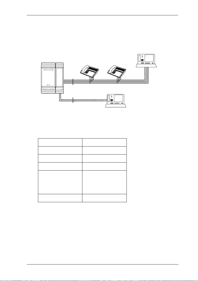
Adding zeroes to SPIDs
Inspect FORWARD Callers
MXP
Inspect FORWARD
Callers
MXP
Working with ISDN / 75
DN 669 (incoming)
SPID 0000066900
DN 670 (outgoing)
SPID 0000067000
DN 667
SPID 066700
S
Loop DN 667
I
n
s
p
e
c
t
F
O
R
W
A
R
D
C
a
ll
e
r
s
M
X
P
DN 668
SPID 066800
I
n
s
p
e
c
t
F
O
R
W
A
R
D
C
a
ll
e
r
s
M
X
P
DN 275
Loop DN 669
SPID 0000027500
U-LT
The following table uses the example in the illustration to
show the programming for the S loop.
Setting Option
Loop 201
Type S
Sampling Fixed
DNs on Loop 201:
Assign DNs
667: Assigned
668: Assigned
669: Assigned
670: Assigned
Loop DN 667
P0603534 02 Modular ICS 6.1 Installer Guide
Page 76

76 / Working with ISDN
ISDN router
By connecting an ISDN router to your Modular ICS, a group
of PCs can share Internet access. This arrangement is best for
a workplace where each personal computer occasionally uses
an Internet connection.
ISDN
ICS
ISDN router
U-LT loop
PCs with
applications
LAN
To support Internet access, you must order BRI lines from
your service provider, and subscribe to an Internet service
from an Internet service provider (ISP). Your personal
computer must have an Internet browser and any applications
supplied by your ISP.
D-packet service (BRI cards only)
The D-packet service supplied by the Modular ICS supports a
point-of-sale terminal adapter (POSTA). Connecting a
POSTA allows transaction terminals, such as devices where
you swipe credit or debit cards, to transmit information using
the D channel of the BRI line. At the same time, the B channels
of the BRI line remain available for voice and data calls. A
special adapter links transaction equipment, such as cash
registers, credit card verification rigs, and point-of-sale
terminals, to the X.25 network. This is a data communications
network designed to transmit information in the form of small
data packets.
Modular ICS 6.1 Installer Guide P0603534 02
Page 77

Working with ISDN / 77
To support the D-packet service, your ISDN network and
financial institution must be equipped with a D-packet
handler. To convert the protocol used by the transaction
equipment to the X.25 protocol, your ISDN network must also
be equipped with an integrated X.25 PAD.
X.25 PAD works with the following versions of X.25: Datapac
32011, CCITT, T3POS, ITT and API. The ISDN service
package you order must include D-packet service, for
example, Package P in the U.S. or Microlink™ with
D-channel in Canada.
Your service provider supplies a Terminal Endpoint Identifier
(TEI) and a DN to support D-packet service. The TEI is a
number between 00 and 63 in the U.S. In Canada, the default
range is 21-63. Your service provider may also supply you
with a DN to program your D-packet device. The DN for
D-packet service becomes part of the dialing string used by the
D-packet to call the packet handler.
POSTA for ISDN BRI
When you configure D-channel packet service, you are
specifying the transmission path between an ISDN loop on the
network side of the ICS and the ISDN loop on the telephone
side. The telephone side loop is the loop used by the point-ofsale terminal adapter. The service is turned on and configured
using the network loop programming found under Hardware.
Use NT loop for BRI-U2 and BRI-U4 cards and S or T loop
for BRI-ST cards.
To set up D-packet service:
• go to the programming settings for the network loop under
Hardware. (S, T, or NT loop)
• select the S loop or LT loop used by the POSTA
P0603534 02 Modular ICS 6.1 Installer Guide
Page 78

78 / Working with ISDN
• enter the terminal endpoint identifiers (TEIs) supplied by
your service provider
Point-of-sale terminal adapter
The point-of-sale terminal adapter is an analog device that
connects to point-of-sale devices using an RS-232 interface
and a U-LT loop. It handles the routing of packet information
from the devices to the ICS and into the ISDN network.
Your service provider, usually a financial institution, supplies
you with information about the compatible controller, which
handles the routing of packet information from the devices to
the ICS and into the ISDN network.
Modular ICS 6.1 Installer Guide P0603534 02
Page 79

Trunks and target lines
Trunks are external lines that provide the physical connection
between a Norstar system and other systems in a private or
public network. Trunks are numbered 001 to 156 in a fully
expanded system. Norstar Modular ICS supports six different
types of trunks:
• PRI trunks are used for incoming and outgoing calls over
an ISDN network. PRI SL-1 lines can provide MCDN
network functionality in a private network between other
Norstar systems, Meridian 1 systems, or Business
Communications Systems, if the appropriate software
code has been installed.
• T1 trunks are digital trunks that can be configured to act as
loop start, ground start, E&M, DID, or leased lines,
depending on your requirements.
— DID trunks route incoming calls from the public
network directly to telephones within Norstar, without
an attendant.
— Loop start trunks handle incoming and outgoing calls
between Norstar and the public network.
— E&M trunks handle incoming and outgoing traffic
between the Norstar system and the private network.
• BRI trunks handle incoming and outgoing calls between
Norstar and an ISDN network.
• Target lines are virtual communication paths between
trunks and telephones on the Norstar system. They are
incoming lines only, and cannot be selected for outgoing
calls. With 192 target lines in a fully expanded system, you
can concentrate auto answer calls on fewer trunks. This
type of concentration is an advantage of target lines.
Norstar mapping allows you to direct each target line to
P0603534 02 Modular ICS 6.1 Installer Guide
Page 80

80 / Trunks and target lines
one or more telephones. Target lines are numbered 157 to
348 in a fully expanded system, and 157 to 284 in all
others.
Telephones can be configured to have an appearance of any
type of trunk and line, including target lines, but excluding PRI
trunks. If assigned, they are used for monitoring call usage.
Trunk operating modes (T1)
T1 trunks have four operating modes:
• ground start (T1 only)
• loopstart (analog and T1)
• E&M (analog and T1)
• DID (analog and T1)
Ground start trunks (T1 only)
Ground start trunks offer the same features as loop start trunks,
but are used when the local service provider does not support
disconnect supervision for the digital loop start trunks. Ground
start trunks work with T1 only.
By configuring lines as ground start, the system will be able to
recognize when a call is released at the far end.
Tips -
start trunk on a DTI. It always has disconnect supervision.
A DTI can provide a maximum of 24 ground start trunks.
Analog ground start trunks are not supported.
Modular ICS 6.1 Installer Guide P0603534 02
You cannot change the trunk mode for a ground
Page 81
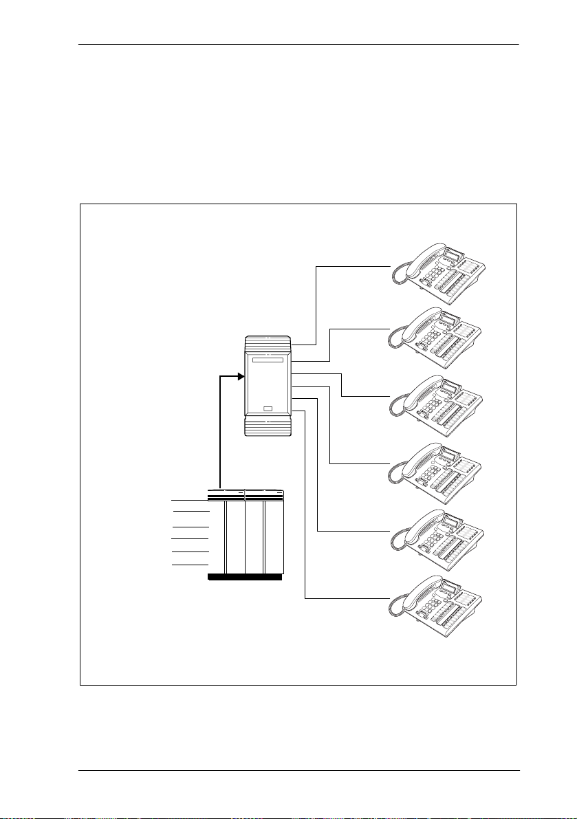
Trunks and target lines / 81
DID trunk s
DID trunks give you direct inward dialing (DID) from the
public network. A typical application of these trunks is to map
incoming digits onto target line appearances within the
Norstar system. DID trunks can operate only as auto-answer
trunks.
Target lines
204
205
206
DID trunk
Norstar
207
593-1234
593-1235
593-1236
593-1237
593-1238
593-1239
Central office (CO)
P0603534 02 Modular ICS 6.1 Installer Guide
208
209
Page 82

82 / Trunks and target lines
When a call comes in on a DID trunk, the Norstar system
interprets the incoming digits in one of the following ways.
• If the digits map onto a target line, the call is routed to all
telephones with an appearance of that target line.
• If the digits map onto the DISA DN, the caller hears
stuttered dial tone. They must enter a six-digit Class of
Service (COS) password from a DTMF telephone to hear
system dial tone.
They can then enter a:
— target line number
— line pool access code
— remote feature code
• If the digits map onto the Auto DN, the caller hears system
dial tone. They can then enter:
— a target line number
— the DISA DN, which will prompt for a Class of Service
password
— a line pool access code
— a destination code
— a remote feature code from a DTMF telephone
Tips -
trunks. Each DID Trunk Cartridge also has four DTMF
receivers dedicated to those trunks. A DTI can provide up to 24
DID trunks.
You cannot configure a DID trunk as the prime line for a
Norstar telephone or a Business Series Terminal.
The capabilities available to a remote caller are determined by
the remote filters and remote package assigned to a line, or by
the set restrictions, line restrictions and remote package
assigned to the Class of Service password.
Modular ICS 6.1 Installer Guide P0603534 02
Each DID Trunk Cartridge can provide four DID
Page 83

Trunks and target lines / 83
Analog loop start trunks
Loop start trunks give you incoming and outgoing access to
the public network. Loop start trunks can be configured as
manual-answer or auto-answer. The answer mode determines
how the system handles incoming calls.
When a call comes in on a manual-answer loop start trunk, it
alerts at all telephones with that line appearance.
When a call comes in on an auto-answer loop start trunk that
is configured to answer with direct inward system access
(DISA), the caller hears a stuttered dial tone. They must enter
a six-digit Class of Service (COS) password from a DTMF
telephone to access system dial tone.
Once the caller has system dial tone, they can then enter:
• a target line number
• a line pool access code
• a remote feature code.
By default, auto answer loop start trunks are configured to
answer with DISA, and are used to provide controlled access
to Norstar system resources.
When a call comes in on an auto-answer loop start trunk that
is not configured to answer with DISA, the caller hears system
dial tone.
They can then enter:
• a target line number
• the DISA DN, which will prompt for a Class of Service
password
• a line pool access code
• a remote feature code from a DTMF telephone
P0603534 02 Modular ICS 6.1 Installer Guide
Page 84

84 / Trunks and target lines
To place an outgoing call, a loop start line can be selected by:
• pressing a line button on the telephone
• dialing a line pool access code
• pressing a memory button that has been programmed with
a line pool access code
Configuration tips
• Loop start signaling is supported by Loop Start Trunk
Cartridges, Call Information (CI) Trunk Cartridges and
Digital Trunk Interfaces (DTI). Each Loop Start Trunk
Cartridge or CI Trunk Cartridge can provide four loop start
trunks. A DTI can provide up to 24 loop start trunks. If you
wish to configure your loop start trunks as auto-answer,
the trunks must have disconnect supervision.
• For Loop Start or CI Trunk Cartridges installed in a Trunk
Module, you will also need one E&M/DISA Trunk
Cartridge for every two loop start trunks that you configure
as auto-answer. The E&M/DISA Trunk Cartridge provides
two DTMF receivers to receive the incoming digits from
the central office. An auto-answer loop start trunk can give
you the same kind of direct inward dialing function as a
DID trunk.
• If your system includes both loop start trunks and DID
trunks, you would typically use loop start trunks for
outgoing calls and DID trunks for incoming calls.
• You may configure a loop start trunk as the prime line for
a Norstar telephone or a Business Series Terminal.
• The capabilities available to a remote caller are determined
by the remote filters and remote package assigned to a line,
or by the set restrictions, line restrictions, and remote
package assigned to the Class of Service password.
Modular ICS 6.1 Installer Guide P0603534 02
Page 85

Trunks and target lines / 85
• Two loopstart trunk cartridges are compatible with
Modular ICS 6.1. The NT5B40GA-93 can be installed in
trunk module (TM) slots only. The NT7B75GA-93 can be
installed in either core slots three or four, or TM slots one,
two, or three.
Analog E&M trunks
An Analog E&M trunk gives you incoming and outgoing
access to other systems in a private network. E&M trunks can
be configured as manual-answer or auto-answer. The answer
mode determines how the system handles incoming calls.
Key system
E&M
PABX
PBX
P0603534 02 Modular ICS 6.1 Installer Guide
intelligent network
PBX
Norstar
Private network
E&M
Key system
E&M
E&M/DISA
Tru nk
Cartridges
Norstar
Page 86

86 / Trunks and target lines
By default, auto-answer E&M trunks are answered by the
system with direct inward system access (DISA), and are used
to provide controlled access to Norstar system resources.
When a call comes in on a manual-answer E&M trunk, it alerts
at all telephones with that line appearance.
When a call comes in on an auto-answer E&M trunk that is
configured to answer with DISA, the caller hears stuttered dial
tone. They must enter a six-digit COS password from a DTMF
telephone to hear system dial tone.
They can then enter a:
• target line number
• line pool access code
• remote feature code
When a call comes in on an auto-answer E&M trunk that is not
configured to answer with DISA, the caller hears system dial
tone. At that point they can then enter one of the following:
• a target line number
• the DISA DN, which will prompt for a COS password
• a line pool access code or a destination code
• a remote feature code from a DTMF telephone
To place an outgoing call, an E&M trunk can be selected by
one of the following:
• pressing a line button on the telephone
• dialing a line pool access code or destination code
• pressing a memory button that has been programmed with
a line pool access code or destination code.
Modular ICS 6.1 Installer Guide P0603534 02
Page 87

Trunks and target lines / 87
BRI trunks
BRI trunks give you incoming and outgoing access to an ISDN
network. Like loop start trunks, they can be configured as
manual-answer or auto-answer. See Ans mode on page 359.
BRI trunks provide a fast, accurate, and reliable means of
sending and receiving data, images, text, and voice
information. Using BRI lines allows for faster transmission
speeds and the addition of a variety of powerful business
applications, including remote LAN access, video
conferencing, file transfer and Internet access.
For more information, see Welcome to ISDN on page 43.
Note Profile 2: European BRI trunks can only be EURO
trunks.
PRI trunks
PRI trunks are used for incoming and outgoing calls over an
ISDN network. PRI trunks are automatically set to autoanswer.
Incoming calls are routed to system telephones through
assigned target lines. Outgoing calls are made using the
intercom key assigned to a PRI line pool, or by entering a
destination code to which a route has been defined using PRI
line pools. You cannot assign a PRI line directly to a
telephone.
PRI Sl-1 lines also can provide MCDN network functionality
over a private network between other Norstar systems,
Meridian 1 systems, or Business Communications Systems, if
the appropriate keycode has been installed. Private networking
is described in Networking with Norstar on page 99.
P0603534 02 Modular ICS 6.1 Installer Guide
Page 88

88 / Trunks and target lines
Target lines
A target line is an internal communication path that is reached
by means of digits received from an incoming trunk. Target
lines are assigned to answer direct-dial incoming calls but they
cannot be used to make outgoing calls.
You can program auto-answer trunks to map to target lines to
provide for attendant bypass, which allows the call to go
directly to a department or individual, and to create line
concentration, where one trunk can map onto several target
lines.
No target lines are automatically assigned to telephones,
except if the DID template has been applied to the system.
Target lines are configured using line numbers 157-348 or
157-284, in the same way as physical lines.
Privacy issue
You can set a target line to Private (default is
Public), however, such features as Call Pickup
can still answer these lines at other telephones in
the group.
Modular ICS 6.1 Installer Guide P0603534 02
Page 89

Remote system access
The remote access feature allows callers elsewhere on the
private or the public network to access a Norstar system by
dialing directly into the system without going through an
attendant. Once in the system, the remote user can use some of
the system resources. The remote access must be enabled in
programming before callers can use it.
Norstar systems support remote system access on the
following trunk types, which may require the remote caller to
enter a COS password for direct inward system access (DISA):
• auto-answer loop start trunks
• auto-answer E&M trunks
• DID trunks, by means of the DISA DN
• PRI trunks, by means of the DISA DN
The system resources, such as dialing capabilities, line pool
access and feature access, that a remote user may access
depends on the Class of Service (COS) assigned to the user.
See Class of Service on page 93, COS pswds on page 401 and
the Modular ICS 6.1 System Coordinator Guide for more
details.
Use system features during a remote call
To use features on a Norstar system during a remote call-in,
press •, followed by the feature code. Even if you are calling
from another Norstar system or from within a private network,
press • instead of ≤.
P0603534 02 Modular ICS 6.1 Installer Guide
Page 90

90 / Remote system access
Remote access on loop start and E&M trunks
Loop start trunks provide remote access to Norstar from the
public network. E&M trunks provide remote access from a
private network. Each must be configured to be auto-answer to
provide remote system access.
A loop start trunk must have disconnect supervision if it is to
operate in auto-answer mode. E&M trunks always operate in
disconnect supervised mode.
When a caller dials into the system on a line that has autoanswer, the system answers with system dial tone and no COS
password is required. In this case, control over the system
capabilities available to the caller is provided only by the
restriction filters assigned to the line.
When a caller dials in on a line that has auto-answer with
DISA, the system answers with stuttered dial tone. This is the
prompt to enter a COS password. The password used by the
caller determines which system capabilities are available to
the caller.
Remote access on a private network
Nodes on the private network deliver the last dialed digits to
the destination Norstar node, for interpretation by the
destination Norstar node. The destination Norstar node either
matches the digits to a target line or interprets the digits as a
remote feature request. The call is either routed to the specified
target line, or the remote feature is activated.
By default, E&M trunks are set to answer with DISA. For
auto-answer E&M trunks connected to a private network,
change the default so that the trunks are not answered with
DISA. If an auto-answer E&M trunk is configured to answer
with DISA, the system tries to interpret any received digits as
a COS password.
Modular ICS 6.1 Installer Guide P0603534 02
Page 91

Remote system access / 91
The DISA DN and the Auto DN allow auto-answer private
network and DID calls, in the same way that calls on
auto-answer loop start and auto-answer E&M trunks can be
answered, with or without DISA. These DNs are described in
System prgming under Access codes.
Remote access on Direct Inward Dial (DID) trunks
Remote system access on DID trunks is similar to that of E&M
trunks connected to a private network.
The main differences are:
• a remote caller is on the public network dialing standard
local or long-distance telephone numbers
• the digits received are delivered by the central office
• DISA cannot be administered to a DID trunk
As with a private network, the dialed digits may be
programmed to match those of a specific target line DN, the
DISA DN or the Auto DN.
Remote access on PRI trunks
Remote system access on PRI trunks is similar to that of E&M
trunks connected to a private network.
The main differences are:
• a remote caller is on the public network dialing standard
local or long-distance telephone numbers
• the digits received are delivered by the central office
• answer with DISA cannot be administered to a PRI trunk
since PRI trunks are set to autoanswer.
As with a private network, the dialed digits may be
programmed to match those of a specific target line DN, the
DISA DN, or the Auto DN.
P0603534 02 Modular ICS 6.1 Installer Guide
Page 92

92 / Remote system access
Modular ICS 6.1 Installer Guide P0603534 02
Page 93

Controlling system access
Modular ICS programming provides several ways of
protecting your Norstar system from unauthorized access or
use. These features are used in combination to provide control
both to users and to lines.
Class of Service
Class of Service (COS) refers to the capabilities that Norstar
provides to users who access the system from the public or
private network. A password defines which set of capabilities
the user has access to.
The COS includes:
• filters that restrict dialing on the line
• an access package defines the set of line pools that may be
accessed and whether or not the user has access to the
paging feature
The COS that is applied to an incoming remote access call is
determined by:
• the filters that you apply to the incoming trunk
• the Class of Service password that the caller used to gain
access to the Norstar system
In cases where DISA is not automatically applied to incoming
calls, the remote caller can change the class of service by
dialing the DISA DN and entering a COS password.
To program COS passwords, see Passwords on page 401 and
the Modular ICS 6.1 System Coordinator Guide.
P0603534 02 Modular ICS 6.1 Installer Guide
Page 94

94 / Controlling system access
Restriction filters
Restriction filters can be used to restrict the numbers that may
be dialed on any external line within your Norstar system. Up
to 100 restriction filters can be created for the system.
A restriction filter consists of up to 48 restrictions with
associated overrides.
To restrict dialing within the system, you can apply filters to:
• outgoing external lines (as line restrictions)
• telephones (as set restrictions)
• external lines on specific telephones (as line/set
restrictions)
Restriction filters can also be specified in Restriction
Service, for times when the system is operating according to
a Schedule. See Services on page 371 for more details.
Dialed digits must pass both the line restrictions and the set
restrictions. The line/set restriction overrides the line
restriction and set restriction. Refer to the following diagrams.
Modular ICS 6.1 Installer Guide P0603534 02
Page 95

Line restrictions
line 1
line 3
line 1
line 3
Set restriction
no long
Set restriction
distance
except area
codes 212,
718
no long
distance
except
area codes
212, 718
Controlling system access / 95
Line restriction
no long
distance except
Line restriction
area codes
212, 718, 214,
no long
distance
713
except area
codes 212
718, 214, 713
no long
distance
no long
distance
line 1
line 1
line 3
line 3
line 5
line 5
line 5
Line/set restriction
restriction
no long
distance except
line 5
area codes
212, 718, 415
Line/Set
no long
distance
except
area codes
212, 718, 415
no long
no long
distance
distance
In the previous diagram, a caller using line 1 could only dial
long-distance numbers to area codes 212 and 718. A caller
using line 3 could not dial any long-distance numbers. A caller
using line 5 could dial long-distance numbers to area codes
212, 718, and 415.
Tips -
an E&M trunk.
To restrict dialing outside the system, once a caller gains
remote access, you can apply restriction filters to incoming
external lines, as remote restrictions.
Set restrictions have no effect on numbers dialed on
P0603534 02 Modular ICS 6.1 Installer Guide
Page 96

96 / Controlling system access
Remote caller restrictions
Line filter
no long
distance
except area
code 212,
718, 416
no long
distance
except area
code 212,
718, 416
Remote
caller
Remote restriction
no long
distance
except area
code 212,
718
Line pool
access
code 81
In this case, dialed digits must pass both the remote restriction
and the line restriction. A remote caller can override these
filters by dialing the DISA DN and entering a COS password.
For restriction filter programming instructions, see
Restrictions on page 339 and the Modular ICS 6.1 System
Coordinator Guide.
Line 1
Line 3
Direct inward system access (DISA )
To control access from the public or private network, you can
configure auto-answer trunks to answer with DISA. Remote
callers hear a stuttered dial tone and must then enter a COS
password. The password they enter determines what access
they are allowed in the system.
Auto-answer loop start and E&M trunks are configured to
answer with DISA by default. For DISA programming
instructions, see Ans with DISA on page 360.
Modular ICS 6.1 Installer Guide P0603534 02
Page 97

Controlling system access / 97
Tips -
provide DTMF receivers for every two auto-answer loop start
trunks on Loop Start or CI Trunk Cartridges.
DID and PRI trunks cannot be configured to answer with
DISA. If you want incoming DID or PRI calls to be answered
with DISA, configure the system with a DISA DN. Incoming
calls that map onto the DISA DN are then routed to a line that
has DISA.
You must have one E&M/DISA Trunk Cartridge to
In addition to public network connections, Norstar Modular
ICS can be integrated into an existing private network, or to
other Norstar or Meridian 1 systems to form a corporate
telecommunications network.
P0603534 02 Modular ICS 6.1 Installer Guide
Page 98

98 / Controlling system access
Modular ICS 6.1 Installer Guide P0603534 02
Page 99

Networking with Norstar
There are a number of ways you can network Norstar systems
together, or network Norstar systems with other Nortel
systems into private networks. What types of lines you use to
perform the networking will determine the type of services
that can be shared between systems.
Keep in mind that each node (Norstar system) is considered an
external system by every other node within the network, even
though, to the users, it appears to be all one system. This
affects how you configure call transfer and call out features on
each system. On the home node, all features are configured as
local numbers. On all other nodes, all features directed to the
home node are configured with external numbers.
As well, each node must have a unique identifying code. What
this code will be, and how it is configured for the user, depends
on what type of trunks and dialing rules you choose to use. If
the network has a Meridian as part of the network, the
Meridian administrator will determine identification codes for
the systems.
This section describes various configurations of private
networks. The general settings that are required to set up the
home node for each system are provided to give you a sense of
what is required for each type of network.
The common goal is to provide the user with the sense that the
network is one large system that provides common access to
colleagues in other buildings, cities, or countries. In some
systems they may need to enter a destination code before the
local number to route the call to the correct system. In other
systems, using a common dialing plan allows users to dial
colleagues at any location simply by entering the same number
of digits they would use to dial a colleague at the next desk.
P0603534 02 Modular ICS 6.1 Installer Guide
Page 100

100 / Tie-line networking
Tie-line networking
Norstar uses enhanced trunking to join other Norstar or
customer equipment in a private network. This allows
authorized users access to tie lines, central office lines, and
Norstar features from outside the Norstar system.
E&M trunks
BRI trunks
DID trunks
T1 trunks
Loop start trunks
PRI trunks
PRI SL-1 trunks
Norstar
Callers using the Norstar Modular ICS system can:
• call directly to a specific Norstar telephone
Public/
Private
Networks
• select an outgoing tie line to access a private network
• select an outgoing tie line to access features that are
available on the private network
• select an outgoing central office line to access the public
network
• use all of the Norstar features
Callers in the public network can:
• call directly to one or more Norstar telephones
• call into the Norstar system and select an outgoing tie line
to access a private network
• call into the Norstar system and select an outgoing central
office line to access the public network
Modular ICS 6.1 Installer Guide P0603534 02
 Loading...