

Nortel 8300, Meridian Link User Manual
Nortel Ethernet Routing Switch 8300
Configuration — VLANs,
Spanning Tree, and Static
Link Aggregation using Device
Manager
NN46200-510 (317348-E Rev 01)
.

Document status: Standard
Document version: 03.01
Document date: 27 August 2007
Copyright © 2005-2007, Nortel Networks
All Rights Reserved.
The information in this document is subject to change without notice. The statements, configurations, technical
data, and recommendations in this document are believed to be accurate and reliable, but are presented without
express or implied warranty. Users must take full responsibility for their applications of any products specified in this
document. The information in this document is proprietary to Nortel Networks.
The software described in this document is furnished under a license agreement and may be used only in accordance
with the terms of that license. The software license agreement is included in this document.
Trademarks
*Nortel, Nortel Networks, the Nortel logo, and the Globemark are trademarks of Nortel Networks.
All other products or services may be trademarks, registered trademarks, service marks, or registered service
marks of their respective owners.
The asterisk after a name denotes a trademarked item.
Restricted rights legend
Use, duplication, or disclosure by the United States Government is subject to restrictions as set forth in subparagraph
(c)(1)(ii) of the Rights in Technical Data and Computer Software clause at DFARS 252.227-7013.
Notwithstanding any other license agreement that may pertain to, or accompany the delivery of, this computer
software, the rights of the United States Government regarding its use, reproduction, and disclosure are as set forth
in the Commercial Computer Software-Restricted Rights clause at FAR 52.227-19.
Statement of conditions
In the interest of improving internal design, operational function, and/or reliability, Nortel Networks reserves the right
to make changes to the products described in this document without notice.
Nortel Networks does not assume any liability that may occur due to the use or application of the product(s) or
circuit layout(s) described herein.
Portions of the code in this software product may be Copyright © 1988, Regents of the University of California. All
rights reserved. Redistribution and use in source and binary forms of such portions are permitted, provided that the
above copyright notice and this paragraph are duplicated in all such forms and that any documentation, advertising
materials, and other materials related to such distribution and use acknowledge that such portions of the software
were developed by the University of California, Berkeley. The name of the University may not be used to endorse or
promote products derived from such portions of the software without specific prior written permission.
SUCH PORTIONS OF THE SOFTWARE ARE PROVIDED "AS IS" AND WITHOUT ANY EXPRESS OR IMPLIED
WARRANTIES, INCLUDING, WITHOUT LIMITATION, THE IMPLIED WARRANTIES OF MERCHANTABILITY AND
FITNESS FOR A PARTICULAR PURPOSE.
In addition, the program and information contained herein are licensed only pursuant to a license agreement that
contains restrictions on use and disclosure (that may incorporate by reference certain limitations and notices
imposed by third parties).
Nortel Networks software license agreement
This Software License Agreement ("License Agreement") is between you, the end-user ("Customer") and Nortel
Networks Corporation and its subsidiaries and affiliates ("Nortel Networks"). PLEASE READ THE FOLLOWING
CAREFULLY. YOU MUST ACCEPT THESE LICENSE TERMS IN ORDER TO DOWNLOAD AND/OR USE THE
SOFTWARE. USE OF THE SOFTWARE CONSTITUTES YOUR ACCEPTANCE OF THIS LICENSE AGREEMENT.
If you do not accept these terms and conditions, return the Software, unused and in the original shipping container,
within 30 days of purchase to obtain a credit for the full purchase price.

"Software" is owned or licensed by Nortel Networks, its parent or one of its subsidiaries or affiliates, and is
copyrighted and licensed, not sold. Software consists of machine-readable instructions, its components, data,
audio-visual content (such as images, text, recordings or pictures) and related licensed materials including all whole
or partial copies. Nortel Networks grants you a license to use the Software only in the country where you acquired the
Software. You obtain no rights other than those granted to you under this License Agreement. You are responsible for
the selection of the Software and for the installation of, use of, and results obtained from the Software.
1.
Licensed Use of Software. Nortel Networks grants Customer a nonexclusive license to use a copy of the
Software on only one machine at any one time or to the extent of the activation or authorized usage level,
whichever is applicable. To the extent Software is furnished for use with designated hardware or Customer
furnished equipment ("CFE"), Customer is granted a nonexclusive license to use Software only on such
hardware or CFE, as applicable. Software contains trade secrets and Customer agrees to treat Software as
confidential information using the same care and discretion Customer uses with its own similar information that it
does not wish to disclose, publish or disseminate. Customer will ensure that anyone who uses the Software
does so only in compliance with the terms of this Agreement. Customer shall not a) use, copy, modify, transferor
distribute the Software except as expressly authorized; b) reverse assemble, reverse compile, reverse engineer
or otherwise translate the Software; c) create derivative works or modifications unless expressly authorized; or d)
sublicense, rent or lease the Software. Licensors of intellectual property to Nortel Networks are beneficiaries of
this provision. Upon termination or breach of the license by Customer or in the event designated hardware or
CFE is no longer in use, Customer will promptly return the Software to Nortel Networks or certify its destruction.
Nortel Networks may audit by remote polling or other reasonable means to determine Customer’s Software
activation or usage levels. If suppliers of third party software included in Software require Nortel Networks to
include additional or different terms, Customer agrees to abide by such terms provided by Nortel Networks
with respect to such third party software.
2. Warranty. Except as may be otherwise expressly agreed to in writing between Nortel Networks and Customer,
Software is provided "AS IS" without any warranties (conditions) of any kind. NORTEL NETWORKS DISCLAIMS
ALL WARRANTIES (CONDITIONS) FOR THE SOFTWARE, EITHER EXPRESS OR IMPLIED, INCLUDING,
BUT NOT LIMITED TO THE IMPLIED WARRANTIES OF MERCHANTABILITY AND FITNESS FOR A
PARTICULAR PURPOSE AND ANY WARRANTY OF NON-INFRINGEMENT. Nortel Networks is not obligated
to provide support of any kind for the Software. Some jurisdictions do not allow exclusion of implied warranties,
and, in such event, the above exclusions may not apply.
3. Limitation of Remedies. IN NO EVENT SHALL NORTEL NETWORKS OR ITS AGENTS OR SUPPLIERS BE
LIABLE FOR ANY OF THE FOLLOWING: a) DAMAGES BASED ON ANY THIRD PARTY CLAIM; b) LOSS
OF, OR DAMAGE TO, CUSTOMER’S RECORDS, FILES OR DATA; OR c) DIRECT, INDIRECT, SPECIAL,
INCIDENTAL, PUNITIVE, OR CONSEQUENTIAL DAMAGES (INCLUDING LOST PROFITS OR SAVINGS),
WHETHER IN CONTRACT, TORT OR OTHERWISE (INCLUDING NEGLIGENCE) ARISING OUT OF YOUR
USE OF THE SOFTWARE, EVEN IF NORTEL NETWORKS, ITS AGENTS OR SUPPLIERS HAVE BEEN
ADVISED OF THEIR POSSIBILITY. The foregoing limitations of remedies also apply to any developer and/or
supplier of the Software. Such developer and/or supplier is an intended beneficiary of this Section. Some
jurisdictions do not allow these limitations or exclusions and, in such event, they may not apply.
4. General
a. If Customer is the United States Government, the following paragraph shall apply: All Nortel Networks
Software available under this License Agreement is commercial computer software and commercial
computer software documentation and, in the event Software is licensed for or on behalf of the United States
Government, the respective rights to the software and software documentation are governed by Nortel
Networks standard commercial license in accordance with U.S. Federal Regulations at 48 C.F.R. Sections
12.212 (for non-DoD entities) and 48 C.F.R. 227.7202 (for DoD entities).
b. Customer may terminate the license at any time. Nortel Networks may terminate the license if Customer
fails to comply with the terms and conditions of this license. In either event, upon termination, Customer
must either return the Software to Nortel Networks or certify its destruction.
c. Customer is responsible for payment of any taxes, including personal property taxes, resulting from
Customer’s use of the Software. Customer agrees to comply with all applicable laws including all applicable
export and import laws and regulations.
d. Neither party may bring an action, regardless of form, more than two years after the cause of the action
arose.
e. The terms and conditions of this License Agreement form the complete and exclusive agreement between
Customer and Nortel Networks.

f. This License Agreement is governed by the laws of the country in which Customer acquires the Software.
If the Software is acquired in the United States, then this License Agreement is governed by the laws of
the state of New York.

5
Contents
New in this release 11
Features 11
Other changes 11
Preface 13
Before you begin 13
How to get help 14
Getting help from the Nortel web site 14
Getting help over the phone from a Nortel Solutions Center 14
Getting help from a specialist using an Express Routing Code 15
Getting help through a Nortel distributor or reseller 15
VLANs, Spanning Tree, and Static Link Aggregation 17
VLANs 17
VLAN ports 18
Port-based VLANs 18
Policy-based VLANs 19
Protocol-based VLANs 20
Independent VLAN Learning (IVL) 22
VLAN tagging and port types 22
VLAN router interfaces 24
VLAN implementation 24
Spanning Tree Protocol (STP) 26
Spanning tree groups 26
Spanning Tree modes 28
Spanning Tree FastStart 28
Understanding STGs and VLANs 28
Spanning Tree Protocol topology change detection 29
Static link aggregation 29
Link aggregation traffic distribution 30
Link aggregation rules 30
Link aggregation examples 31
Split MultiLink Trunking 34
Overview 35
Advantages of SMLT 36
Nortel Ethernet Routing Switch 8300
Configuration — VLANs, Spanning Tree, and Static Link Aggregation using Device Manager
NN46200-510 03.01 Standard
4.0 27 August 2007
Copyright © 2005-2007, Nortel Networks
.

6 Contents
How SMLT works 38
Inter-Switch Trunks 40
CP-Limit and SMLT IST 41
Traffic flow in an SMLT environment 42
Single port SMLT 44
SMLT topologies 45
Using MLT-based SMLT with single port SMLT 49
SMLT network design considerations 50
SMLT and VRRP backup master 51
Simple Loop Prevention Protocol 52
Port auto recovery 54
VLAN, STG, and link aggregation feature support 55
Configuring VLANs 57
Understanding VLAN ports 57
Displaying defined VLANs 58
Creating a VLAN 60
Creating a port-based VLAN 61
Configuring an IP address for a VLAN 62
Creating a protocol-based VLAN 63
Configuring user-defined protocol-based VLANs 66
Managing a VLAN 68
Changing VLAN port membership 68
Configuring advanced VLAN features 69
Configuring a MAC address for auto-learning on a VLAN 73
Managing the VLAN forwarding database 76
Configuring aging in the VLAN forwarding database 76
Configuring static forwarding 80
Configuring VLAN forwarding database filters 83
Configuring Layer 2 multicast MAC filtering 85
Configuring port auto recovery 87
Configuring auto recovery delay time 87
Enabling or disabling port auto recovery for a single port 88
Enabling or disabling port auto recovery for multiple ports 89
Configuring Spanning Tree Group 91
Configuring Simple Loop Prevention Protocol 103
Configuring SLPP globally 103
Configuring the SLPP by VLAN 104
Configuring the SLPP by port 106
Configuring static link aggregation 109
Link aggregation traffic distribution 109
Adding a link aggregation group 110
Viewing link aggregation interface statistics 114
Configuring SMLT 120
Nortel Ethernet Routing Switch 8300
Configuration — VLANs, Spanning Tree, and Static Link Aggregation using Device Manager
NN46200-510 03.01 Standard
4.0 27 August 2007
Copyright © 2005-2007, Nortel Networks
.

Contents 7
Adding an MLT-based SMLT 120
Viewing MLT-based SMLT information for the switch 121
Configuring a single port SMLT 122
Viewing single port SMLTs configured on the switch 123
Deleting a single port SMLT 124
Configuring an IST MLT 124
Removing an IST MLT 125
Viewing IST statistics 126
Index 128
Figures
Figure 1 Port-based VLAN 19
Figure 2 Dynamic protocol-based VLAN 21
Figure 3 VLAN tag insertion 22
Figure 4 Multiple spanning tree groups 27
Figure 5 Switch-to-switch link aggregation configuration 32
Figure 6 Switch-to-server link aggregation configuration 33
Figure 7 Client/Server link aggregation configuration 34
Figure 8 Resilient networks with Spanning Tree Protocol 37
Figure 9 Resilient networks with SMLT 38
Figure 10 8300 switches as SMLT aggregation switches 39
Figure 11 show vlan info fdb-entry 10 sample output 43
Figure 12 Network topology for traffic flow example 43
Figure 13 Single port SMLT example 45
Figure 14 Single Port SMLT topology 46
Figure 15 SMLT triangle topology 47
Figure 16 SMLT square topology 48
Figure 17 SMLT full mesh topology 49
Figure 18 Changing a split trunk from MLT-based SMLTto single port SMLT 50
Figure 19 SLPP frame 53
Figure 20 VLAN dialog box - Basic tab 58
Figure 20 VLAN, Insert Basic dialog box for port-based VLANs 61
Figure 20 VlanPortMembers dialog box 62
Figure 20 IP, VLAN dialog box 63
Figure 20 IP, VLAN, Insert IP Address dialog box 63
Figure 20 VLAN, Insert Basic dialog box for protocol-based VLANs 64
Figure 20 VlanPortMembers dialog box 65
Figure 20 VLAN, Insert Basic: insert a user-defined, protocol-based VLAN 67
Figure 20 PortMembers, VLAN dialog box 68
Figure 20 VLAN dialog box - Advanced tab 69
Figure 20 Port dialog box - Interface tab 72
Figure 20 Port dialog box - VLAN tab 72
Figure 20 VlanMacLearning dialog box - Manual Edit tab 74
Figure 20 VlanMacLearning, Insert Manual Edit dialog box 74
Figure 20 BridgeManualEditPorts dialog box 74
Figure 20 VlanMacLearning dialog box - Auto Learn tab 75
Figure 20 Bridge, VLAN dialog box - Transparent tab 76
Figure 20 Bridge, VLAN dialog box - Forwarding tab 78
Nortel Ethernet Routing Switch 8300
Configuration — VLANs, Spanning Tree, and Static Link Aggregation using Device Manager
NN46200-510 03.01 Standard
4.0 27 August 2007
Copyright © 2005-2007, Nortel Networks
.

8 Contents
Figure 20 VLAN dialog box - Advanced tab: flushing the forwarding
database 79
Figure 20 Bridge, VLAN - Static tab 81
Figure 20 Bridge, VLAN, Insert Static dialog box 81
Figure 20 Bridge, VLAN, Insert Filter dialog box 83
Figure 20 STG dialog box - Globals tab 92
Figure 20 STG dialog box - Configuration tab 93
Figure 20 STG, Insert Configuration dialog box 93
Figure 20 StgPortMembers dialog box 94
Figure 20 STG dialog box - Status tab 97
Figure 20 STG dialog box - Ports tab 99
Figure 20 MLT dialog box - MultiLink Trunks tab 110
Figure 20 MLT, Insert MultiLink Trunks dialog box 111
Figure 20 MltPortMembers dialog box 111
Figure 20 VlanIds dialog box 112
Figure 20 Statistics, MLT dialog box - Interface tab 115
Figure 20 Statistics, MLT dialog box - Ethernet Errors tab 117
Figure 20 Statistics, MLT dialog box - Interface Utilization tab 119
Figure 20 Multilink Trunks tab on the MLT dialog box 121
Figure 20 SMLT Info tab on the SMLT dialog box 122
Figure 20 SMLT tab on the Port dialog box 122
Figure 20 Insert SMLT dialog box 123
Figure 20 Single Port SMLT tab on the SMLT dialog box 123
Figure 20 IST MLT dialog box 125
Figure 20 Ist/SMLT Stats tab on the MLT dialog box 127
Tables
Table 1 Port membership types for policy-based VLANS 19
Table 2 PIDs not available for user-defined protocol-based VLANs 21
Table 3 VLAN rules 25
Table 4 Spanning Tree Protocol topology change detection configuration
rules 29
Table 5 Methods of traffic distribution for packets with a trunk destination 30
Table 6 SLPP frame fields 53
Table 7 VLAN, STG, and link aggregation support 55
Table 8 VLAN - Basic tab fields 59
Table 9 VLAN - Advanced tab fields 70
Table 10 VlanMacLearning - Insert Manual Edit tab fields 75
Table 11 Bridge ,VLAN dialog box - Transparent tab fields 77
Table 12 Bridge, VLAN dialog box - Forwarding tab fields 78
Table 13 Bridge , VLAN - Static tab fields 82
Table 14 Bridge, VLAN dialog box - Filter tab fields 84
Table 15 Bridge, VLAN, Insert Multicast tab fields 86
Table 16 STG Configuration tab fields 94
Table 17 STG Status tab fields 97
Table 18 STG Ports tab fields 99
Table 19 SLPP - Global tab fields 104
Table 20 SLPP - Insert VLANS window fields 106
Table 21 SLPP - Ports tab fields 107
Table 22 MLT dialog box - MultiLink Trunks fields 112
Table 23 Statistics, MLT dialog box - Interface tab fields 115
Nortel Ethernet Routing Switch 8300
Configuration — VLANs, Spanning Tree, and Static Link Aggregation using Device Manager
NN46200-510 03.01 Standard
4.0 27 August 2007
Copyright © 2005-2007, Nortel Networks
.

Contents 9
Table 24 Statistics, MLT dialog box - Ethernet Errors tab fields 117
Table 25 Statistics, MLT dialog box - Interface Utilization tab fields 120
Nortel Ethernet Routing Switch 8300
Configuration — VLANs, Spanning Tree, and Static Link Aggregation using Device Manager
NN46200-510 03.01 Standard
4.0 27 August 2007
Copyright © 2005-2007, Nortel Networks
.

10 Contents
Nortel Ethernet Routing Switch 8300
Configuration — VLANs, Spanning Tree, and Static Link Aggregation using Device Manager
NN46200-510 03.01 Standard
4.0 27 August 2007
Copyright © 2005-2007, Nortel Networks
.

11
New in this release
The following sections detail what is new in Configuration — VLANs,
Spanning Tree, and Static Link Aggregation using Device Manager
(NN46200-510) for Release 4.0.
•
"Features" (page 11)
•
"Other changes" (page 11)
Features
See the following sections for information about feature changes:
•
"Simple Loop Prevention Protocol" (page 52)
•
"Configuring Simple Loop Prevention Protocol" (page 103)
•
"Port auto recovery" (page 54)
Other changes
See the following sections for information about changes that reflect the
upgrade to eight port multilink trunking (MLT) for this release:
•
Table 22 "MLT dialog box - MultiLink Trunks fields" (page 112)
•
"Adding ports to a link aggregation group" (page 113)
• "Adding an MLT-based SMLT" (page 120)
•
"Link aggregation rules" (page 30)
Nortel Ethernet Routing Switch 8300
Configuration — VLANs, Spanning Tree, and Static Link Aggregation using Device Manager
NN46200-510 03.01 Standard
4.0 27 August 2007
Copyright © 2005-2007, Nortel Networks
.

12 New in this release
Nortel Ethernet Routing Switch 8300
Configuration — VLANs, Spanning Tree, and Static Link Aggregation using Device Manager
NN46200-510 03.01 Standard
4.0 27 August 2007
Copyright © 2005-2007, Nortel Networks
.

13
Preface
The Nortel* Ethernet Routing Switch (ERS) 8300 is a flexible and
multifunctional Layer 2/Layer 3 switch that supports diverse network
architectures and protocols. The ERS 8300 provides security and control
features such as Extensible Authentication Protocol over LAN (EAPoL),
Simple Network Management Protocol, Version 3 (SNMP3), and Secure
Shell (SSH). The ERS 8300 provides quality of service (QoS) for a high
number of attached devices and supports future network requirements for
QoS for critical applications, such as Voice over IP (VoIP).
Java Device Manager (Device Manager) is a graphical user interface (GUI)
used to configure and manage 8300 Series switches. You install it on a
management station in the network. For instructions on installing and
starting Device Manager on a Windows*, UNIX*, or Linux* platform, refer
to
Nortel Ethernet Routing Switch 8300 Fundamentals — Using Device
Manager (NN46200-303). The manual also describes some common
startup problems and how to troubleshoot them.
This guide describes how to use Device Manager to configure VLANs,
spanning tree, and static link aggregation for the 8300 Series switches.
Before you begin
This guide is intended for network administrators who have the following
background:
•
basic knowledge of networks, Ethernet bridging, and IP routing
•
familiarity with networking concepts and terminology
•
experience with windowing systems or GUIs
•
basic knowledge of network topologies
Before using this guide, you must complete the following procedures. For a
new switch:
Step Action
1
Install the switch.
Nortel Ethernet Routing Switch 8300
Configuration — VLANs, Spanning Tree, and Static Link Aggregation using Device Manager
NN46200-510 03.01 Standard
4.0 27 August 2007
Copyright © 2005-2007, Nortel Networks
.

14 Preface
Forinstallation instructions, see Nortel Ethernet Routing Switch 8300
Installation — Chassis Installation and Maintenance (NN46200-304)
andNortel Ethernet Routing Switch 8300 Installation — Modules
(NN46200-305).
2
Connect the switch to the network.
For more information, see Getting Started (316799-C).
—End—
Ensure that you are running the latest version of Nortel ERS 8300 software.
For information about upgrading the ERS 8300, see Nortel Ethernet Routing
Switch 8300 Upgrades — Software Release 4.0(NN46200-400).
How to get help
This section explains how to get help for Nortel products and services.
Getting help from the Nortel web site
The best way to get technical support for Nortel products is from the Nortel
Technical Support web site:
w
ww.nortel.com/support
This site provides quick access to software, documentation, bulletins, and
tools to address issues with Nortel products. From this site, you can:
•
Download software, documentation, and product bulletins.
•
Search the Technical Support Web site and the Nortel Knowledge Base
for answers to technical issues.
•
Sign up for automatic notification of new software and documentation
for Nortel equipment.
•
Open and manage technical support cases.
Getting help over the phone from a Nortel Solutions Center
If you do not find the information you require on the Nortel Technical Support
web site, and you have a Nortel support contract, you can also get help over
the phone from a Nortel Solutions Center.
In North America, call 1-800-4NORTEL (1-800-466-7835).
Outside North America, go to the following web site to obtain the phone
number for your region:
www.nortel.com/callus
Nortel Ethernet Routing Switch 8300
Configuration — VLANs, Spanning Tree, and Static Link Aggregation using Device Manager
NN46200-510 03.01 Standard
4.0 27 August 2007
Copyright © 2005-2007, Nortel Networks
.

How to get help 15
Getting help from a specialist using an Express Routing Code
To access some Nortel Technical Solutions Centers, you can use an Express
Routing Code (ERC) to quickly route your call to a specialist in your Nortel
product or service. To locate the ERC for your product or service, go to:
www.nortel.com/erc
Getting help through a Nortel distributor or reseller
If you purchased a service contract for your Nortel product from a distributor
or authorized reseller, contact the technical support staff for that distributor
or reseller.
Nortel Ethernet Routing Switch 8300
Configuration — VLANs, Spanning Tree, and Static Link Aggregation using Device Manager
NN46200-510 03.01 Standard
4.0 27 August 2007
Copyright © 2005-2007, Nortel Networks
.

16 Preface
Nortel Ethernet Routing Switch 8300
Configuration — VLANs, Spanning Tree, and Static Link Aggregation using Device Manager
NN46200-510 03.01 Standard
4.0 27 August 2007
Copyright © 2005-2007, Nortel Networks
.

17
VLANs, Spanning Tree, and Static Link
Aggregation
This chapter describes Virtual LANs, spanning tree groups, and link
aggregation. The following topics are included:
•
"VLANs" (page 17)
•
"Spanning Tree Protocol (STP)" (page 26)
•
"Static link aggregation" (page 29)
•
"Split MultiLink Trunking" (page 34)
•
"Simple Loop Prevention Protocol" (page 52)
•
"Port auto recovery" (page 54)
•
"VLAN, STG, and link aggregation feature support" (page 55)
VLANs
With a virtual LAN (VLAN), you can divide your LAN into smaller groups
without interfering with the physical network. You can use VLANs to:
•
Create workgroups for common interest groups.
•
Create workgroups for specific types of network traffic.
•
Add, move, or delete members from these workgroups without making
any physical changes to the network.
By dividing the network into separate VLANs, you can create separate
broadcast domains. This conserves bandwidth, especially in networks
supporting broadcast and multicast applications that flood the network with
traffic. A VLAN workgroup can include members from a number of dispersed
physical segments on the network, improving traffic flow between them.
The ERS 8300 performs the layer 2 switching functions necessary to
transmit information within VLANs as well as the layer 3 routing functions
necessary for VLANs to communicate with one another. A VLAN can be
defined for a single switch or it can span multiple switches. A port can be a
member of multiple VLANs.
Nortel Ethernet Routing Switch 8300
Configuration — VLANs, Spanning Tree, and Static Link Aggregation using Device Manager
NN46200-510 03.01 Standard
4.0 27 August 2007
Copyright © 2005-2007, Nortel Networks
.

18 VLANs, Spanning Tree, and Static Link Aggregation
The ERS 8300 supports port-based VLANs and policy-based VLANs.
This section includes the following topics:
•
"VLAN ports" (page 18)
• "Port-based VLANs" (page 18)
•
"Policy-based VLANs" (page 19)
•
"Protocol-based VLANs" (page 20)
• "Independent VLAN Learning (IVL)" (page 22)
•
"VLAN tagging and port types" (page 22)
•
"VLAN router interfaces" (page 24)
•
"VLAN implementation" (page 24)
VLAN ports
A Virtual LAN is made up of a group of ports that define a logical broadcast
domain. These ports can belong to a single switch, or they can be spread
across multiple switches. In a VLAN-aware switch, every frame received
on a port is classified as belonging to only one VLAN. Whenever a
broadcast, multicast, or unknown destination frame needs to be flooded by
a VLAN-aware switch, the frame is sent out through only the other active
ports that are members of this VLAN.
The default switch configuration groups all ports into the port-based default
VLAN 1. This VLAN cannot be deleted from the system, and is statically
bound to the default spanning tree group (STG).
Port-based VLANs
A port-based VLAN is a VLAN with ports explicitly configured as members.
When creating a port-based VLAN, you assign a VLAN identification
number (VID) and specify the ports that belong to the VLAN. The VID is
used to coordinate VLANs across multiple switches.
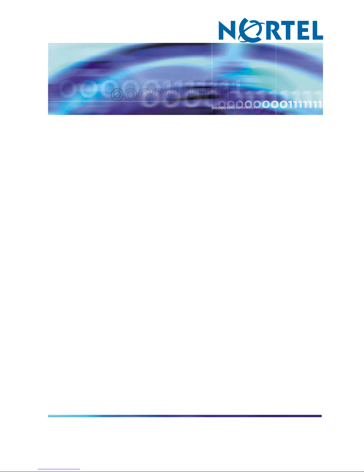
The example in Figure 1 "Port-based VLAN" (page 19) shows two
port-based VLANs: one for the marketing department and one for the sales
department. Ports are assigned to each port-based VLAN. A change in the
sales area can move the sales representative at port 3/1 (the first port in the
I/O module in chassis slot 3) to the marketing department without moving
cables. With a port-based VLAN, you only need to indicate in Device
Manager or the CLI that port 3/1 in the sales VLAN now is a member of
the marketing VLAN.
Nortel Ethernet Routing Switch 8300
Configuration — VLANs, Spanning Tree, and Static Link Aggregation using Device Manager
NN46200-510 03.01 Standard
4.0 27 August 2007
Copyright © 2005-2007, Nortel Networks
.
VLANs 19
Figure 1
Port-based VLAN
Policy-based VLANs
The ERS 8300 supports a total of 500 unique policy-based VLANS.
However, there are some restrictions on the number of types of policy-based
VLANs.
In a policy-based VLAN, a port can be designated as always a member or
never a member. Table 1 "Port membership types for policy-based VLANS"
(page 19) describes these port membership types.
Table 1
Port membership types for policy-based VLANS
Membership type Description
Static(Always a member) Static members are always active members of
the VLAN, when configured as belonging to
that VLAN. This membership type is used in
policy-based and port-based VLANs.
•
In policy-based VLANs, the tagged ports
are usually configured as static members.
•
In port-based VLANs, all ports are always
static members.
Not allowed to join
(Never a member)
Ports of this type are not allowed to join the
VLAN.
Nortel Ethernet Routing Switch 8300
Configuration — VLANs, Spanning Tree, and Static Link Aggregation using Device Manager
NN46200-510 03.01 Standard
4.0 27 August 2007
Copyright © 2005-2007, Nortel Networks
.

20 VLANs, Spanning Tree, and Static Link Aggregation
A non-tagged port can belong to multiple VLANs, as long as the VLANs are
not of the same type but are in the same spanning tree group.
Protocol-based VLANs
Protocol-based VLANs are an effective way to segment your network
into broadcast domains according to the network protocols in use. Traffic
generated by any network protocol — IPX, Appletalk, and so forth — can be
automatically confined to its own VLAN.
Port tagging is not required for a port to be a member of multiple
protocol-based VLANs.
The ERS 8300 supports the following protocol-based VLANs:
• IP version 4 (ip)
•
Novell IPX on Ethernet 802.3 frames (ipx802dot3)
•
Novell IPX on IEEE 802.2 frames (ipx802dot2)
•
Novell IPX on Ethernet SNAP frames (ipxSnap)
•
Novell IPX on Ethernet Type 2 frames (ipxEthernet2)
•
AppleTalk on Ethernet Type 2 and Ethernet SNAP frames (AppleTalk)
•
DEC LAT Protocol (decLat)
•
Other DEC protocols (decOther)
•
IBM SNA on IEEE 802.2 frames (sna802dot2)
•
IBM SNA on Ethernet Type 2 frames (snaEthernet2)
•
NetBIOS Protocol (netBIOS)
•
Xerox XNS (xns)
•
Banyan VINES (vines)
•
IP version 6 (ipv6)
•
Reverse Address Resolution Protocol (RARP)
•
User-defined protocols
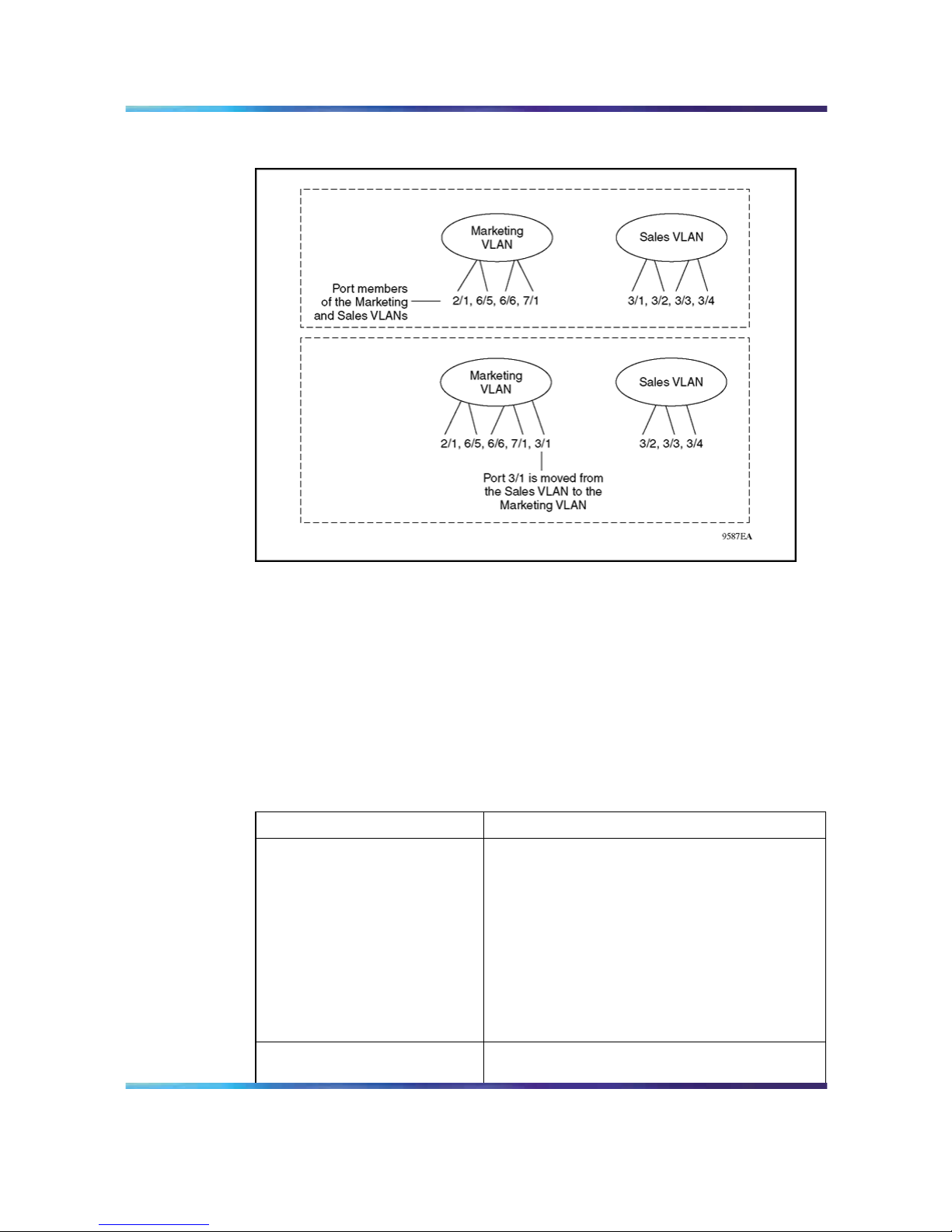
Example: IPX protocol-based VLAN
You can create a VLAN for the IPX protocol and place ports carrying
substantial IPX traffic into this new VLAN.
In Figure 2 "Dynamic protocol-based VLAN" (page 21), the network
manager placed ports 7/1, 3/1, and 3/2 in an IPX VLAN. These ports still
belong to their respective marketing and sales VLANs, but they are also new
members of the IPX VLAN. This arrangement localizes traffic and ensures
that only three ports are flooded with IPX broadcast packets.
Nortel Ethernet Routing Switch 8300
Configuration — VLANs, Spanning Tree, and Static Link Aggregation using Device Manager
NN46200-510 03.01 Standard
4.0 27 August 2007
Copyright © 2005-2007, Nortel Networks
.
VLANs 21
Figure 2
Dynamic protocol-based VLAN
User-defined protocol-based VLANs
You can create user-defined protocol-based VLANs in support of networks
with non-standard protocols. For user-defined protocol-based VLANs, you
can specify the Protocol Identifier (PID) for the VLAN. For release 2.1, you
can enter the PID as a range of hexadecimal identifiers separated by a
comma (,) a dash (-), or some combination of the two. Note that you can
provide a maximum of 8 PIDs in this range.
Frames that match the specified PID for the following are assigned to that
user-defined VLAN:
•
the ethertype for Ethernet type 2 frames
• the PID in Ethernet SNAP frames
•
the DSAP or SSAP value in Ethernet 802.2 frames
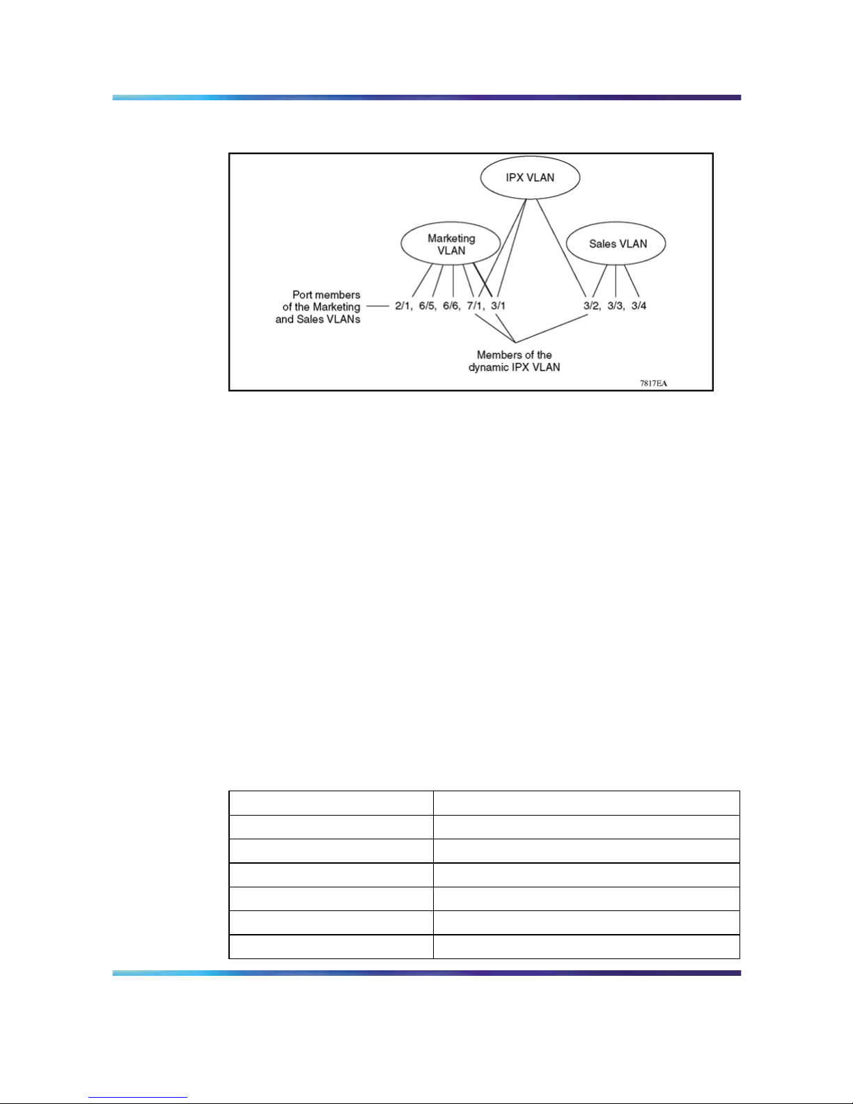
Table 2 "PIDs not available for user-defined protocol-based VLANs" (page
21) lists the predefined policy-based PIDs, which are reserved and cannot
be designated as user-defined PIDs.
Table 2
PIDs not available for user-defined protocol-based VLANs
PID (hex) Description
04xx, xx04
sna802dot2
F0xx, xxF0 netBIOS
0000-05DC Overlaps with 802.3 frame length
0600, 0807
xns
0BAD VINES
4242
IEEE 802.1D BPDUs
Nortel Ethernet Routing Switch 8300
Configuration — VLANs, Spanning Tree, and Static Link Aggregation using Device Manager
NN46200-510 03.01 Standard
4.0 27 August 2007
Copyright © 2005-2007, Nortel Networks
.
22 VLANs, Spanning Tree, and Static Link Aggregation
PID (hex) Description
0800
IP
0806
ARP
8035
RARP
809B, 80F3 AppleTalk
8100
Reserved by IEEE 802.1Q for tagged frames
8137, 8138
ipxEthernet2 and ipxSnap
80D5 snaEthernet2
86DD ipv6
8808
IEEE 802.3x pause frames
9000
Used by diagnostic loopback frames
Independent VLAN Learning (IVL)
In the ERS 8300, each VLAN has its own, independent, forwarding
database. That is, the same MAC address can be learned in different
VLANs; and, based on the VLAN receiving traffic for this address, the
switch is able to forward to this MAC address without any confusion. This
means that before the switch can look up the source or destination MAC
address in a received frame, or before it can decide whether to bridge or
to route a frame, it must first determine the VLAN that the frame belongs
to. The IVL mode is used to learn MAC addresses in the context of the
VLAN they belong to.
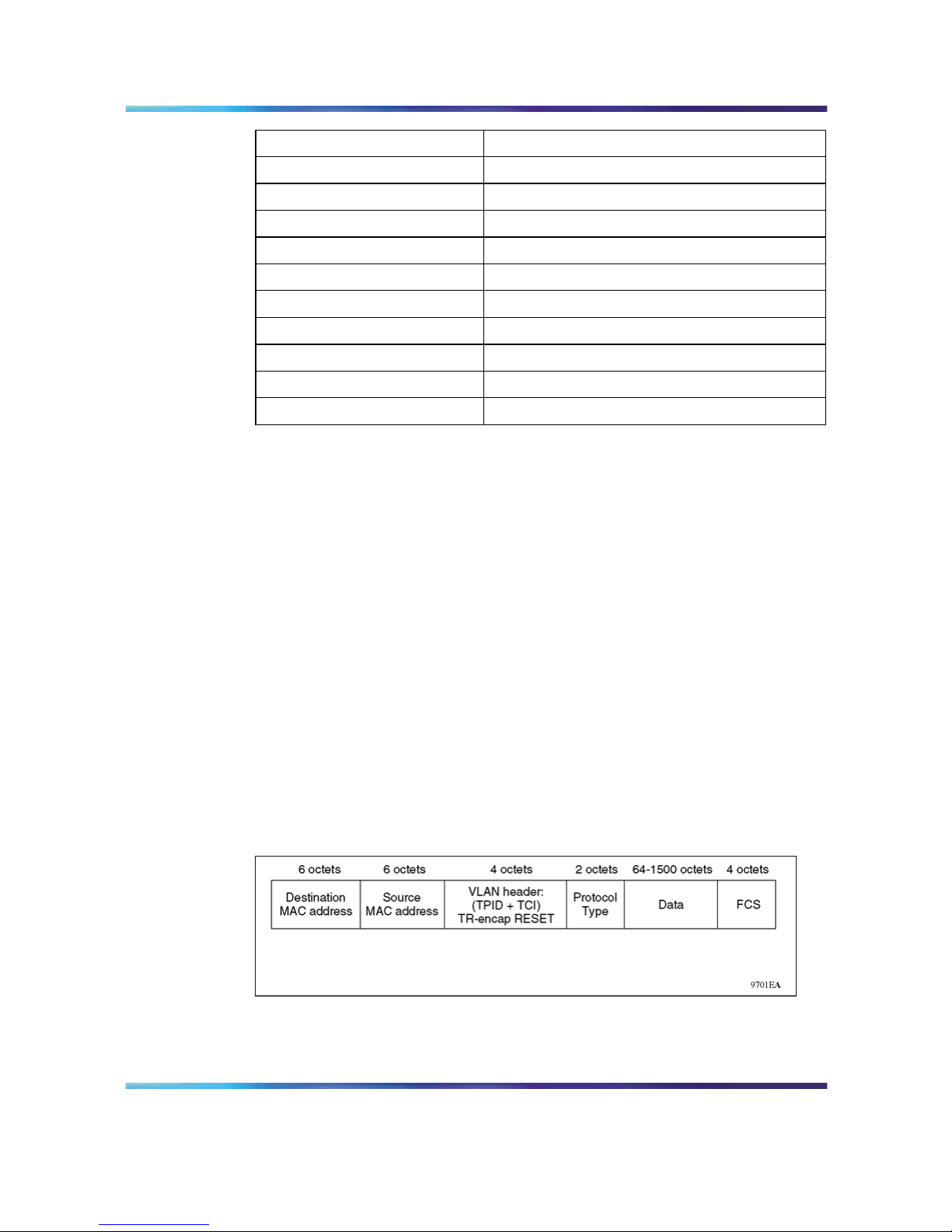
VLAN tagging and port types
The ERS 8300 uses IEEE 802.1Q tagging of frames and coordinating
VLANs across multiple switches. Figure 3 "VLAN tag insertion" (page
22) shows the additional 4-octet (tag) header inserted into a frame after the
source address and before the frame type. The tag contains the VLAN ID
associated with the frame.
Figure 3
VLAN tag insertion
Nortel Ethernet Routing Switch 8300
Configuration — VLANs, Spanning Tree, and Static Link Aggregation using Device Manager
NN46200-510 03.01 Standard
4.0 27 August 2007
Copyright © 2005-2007, Nortel Networks
.

VLANs 23
802.1Q tagged ports
Tagging a frame adds four octets to a frame, making it bigger than the
traditional maximum frame size. These frames are sometimes referred to
as "baby giant" frames. If a device does not support IEEE 802.1Q tagging,
it can have problems interpreting tagged frames and receiving baby giant
frames.
In the ERS 8300, your port level configuration determines whether tagged
frames are sent and received. Tagging is set as true or false for the port and
is applied to all VLANs on that port.
When you enable tagging on an untagged port, the port’s previous
configuration of VLANs and STGs is lost. In addition, the port resets and
runs Spanning Tree Protocol, thus breaking connectivity while the protocol
goes through the normal listening and learning states before the forwarding
state.
A ERS 8300 port with tagging enabled sends frames explicitly tagged with a
VLAN ID. Tagged ports are typically used to multiplex traffic belonging to
multiple VLANs to other IEEE-802.1Q-compliant devices.
If tagging is disabled on a ERS 8300 port, it does not send tagged frames.
A nontagged port connects the ERS 8300 to devices that do not support
IEEE 802.1Q tagging. If a tagged frame is forwarded out a port on which
tagging is set to false, the switch removes the tag from the frame before
sending it out the port.
If a port is set for tagging on a ERS 8300, and the port is also a member of
an untagged multilink trunk (MLT), or the reverse is true. The port settings
on the MLT overrides.
Treatment of tagged and untagged frames
A ERS 8300 associates a frame with a VLAN based on the data content of
the frame and the configuration of the destination port. Whether the frame
is tagged or untagged dictates how that frame is treated.
If a tagged frame is received on a tagged port, with a VLAN ID specified in
the tag, the ERS 8300 directs it to that VLAN, if it is present.
For untagged frames, VLAN membership is implied from the content of
the frame itself. For untagged frames received on a tagged port, you can
configure the port to either discard or accept the frame. If you configure
a tagged port to accept untagged frames, the port must be assigned to
a port-based VLAN.
On the ERS 8300 you have the option to configure tagged ports to send
untagged frames on the default VLAN of the port.
Nortel Ethernet Routing Switch 8300
Configuration — VLANs, Spanning Tree, and Static Link Aggregation using Device Manager
NN46200-510 03.01 Standard
4.0 27 August 2007
Copyright © 2005-2007, Nortel Networks
.

24 VLANs, Spanning Tree, and Static Link Aggregation
How the frame is forwarded is based on the VLAN the frame is received
and on the forwarding options available for that VLAN. A ERS 8300 tries to
associate untagged frames with a VLAN in the following order:
•
Does the frame belong to a protocol-based VLAN?
•
What is the port-based VLAN of the receiving port?
If the frame meets none of the preceding criteria, it is discarded.
VLAN router interfaces
Virtual router interfaces correspond to routing on a virtual port associated
with a VLAN. This type of routing is the routing of IP traffic to and from a
VLAN. Because a given port can belong to multiple VLANs (some of which
are configured for routing on the switch and some of which are not), there is
not a one-to-one correspondence between the physical port and the router
interface. For VLAN routing, the router interface for the VLAN is called a
virtual router interface because the IP address is assigned to an interface
on the routing entity in the switch. This initial interface has a one-to-one
correspondence with a VLAN on any given switch.
The ERS 8300 chassis supports 4096 MAC addresses. If you are using
an 8600 chassis, make sure it supports 4096 MAC addresses. You can
install the 8600 MAC upgrade kit to support 4096 MAC addresses. For
more information, see the publication, Adding MAC addresses to the 8600
Series Switch (part number 212486-A).
VLAN implementation
This section describes how to implement VLANs on a ERS 8300. The
following topics are included:
• "Default VLANs" (page 24)
•
"Unassigned VLANs" (page 24)
•
"VLAN rules" (page 25)
Default VLANs
The ERS 8300 is factory configured with all ports residing in a port-based
VLAN and default spanning tree group (STG) 1. With all ports in this default
VLAN, the switch behaves like a layer 2 switch. The VLAN ID of this default
VLAN is always 1, and it is always a port-based VLAN. The default VLAN
cannot be deleted.
Unassigned VLANs
The unassigned VLAN is a port-based VLAN that acts as a placeholder for
ports that are removed from other port-based VLANs. Ports can belong to
policy-based VLANs as well as to the unassigned VLAN. If a frame does not
meet any policy criteria and there is no underlying port-based VLAN, the
Nortel Ethernet Routing Switch 8300
Configuration — VLANs, Spanning Tree, and Static Link Aggregation using Device Manager
NN46200-510 03.01 Standard
4.0 27 August 2007
Copyright © 2005-2007, Nortel Networks
.
VLANs 25
port belongs to the unassigned VLAN and the frame is dropped. Only ports
in the unassigned VLAN have no spanning tree group association, so they
do not participate in Spanning Tree Protocol negotiation; that is, no BPDUs
are sent out of ports in the unassigned VLAN.
The unassigned VLAN cannot be deleted or viewed. If a user-defined
spanning tree group is deleted, the ports are moved to the unassigned
VLAN and can later be assigned to another spanning tree group. Moving
the ports to the unassigned VLAN avoids creating unwanted loops and
duplicate connections. If routing is disabled in these ports, the port is
completely isolated and no layer 2 or layer 3 functionality is provided.
The unassigned VLAN is useful for security concerns or when using a port
for monitoring a mirrored port.
VLAN rules
Table 3 "VLAN rules" (page 25) describes the VLAN rules for the ERS 8300.
Table 3
VLAN rules
•
In addition to the default VLAN, the ERS 8300 supports 4000 VLANs. VLAN IDs range in
value from 1 to 4000. See note
1
•
If you enable tagging on a port in a VLAN, the spanning tree group configuration for that port is
lost. To preserve VLAN assignment of ports, enable tagging on the ports before you assign
the ports to VLANs.
•
Tagged ports can belong to multiple VLANs and multiple spanning tree groups. When a tagged
port belongs to multiple spanning tree groups, the BPDUs are tagged for all spanning tree
groups except for spanning tree group number 1. Under the default configuration, the default
is spanning tree group number 1.
•
An untagged port can belong to only one port-based VLAN. A port in a port-based VLAN can
belong to other policy-based VLANs.
•
An untagged port can belong to only one policy-based VLAN for a given protocol. For example,
a port can belong to only one policy-based VLAN where the policy is IPX802dot2 protocol.
•
A VLAN cannot span multiple spanning tree groups; that is, the ports in the VLAN must all
be within one spanning tree group. Spanning tree group IDs can range in value from 1 to
64. See note
1
•
A frame’s VLAN membership is determined by the following order of precedence:
1. VLAN ID in the frame’s VLAN tag
2. protocol-based VLAN
3. port-based VLAN
1
Also see Nortel Ethernet Routing Switch 8300 Release Notes — Software Release
4.0(NN46200-401) for the latest information about supported software and hardware capabilities.
Nortel Ethernet Routing Switch 8300
Configuration — VLANs, Spanning Tree, and Static Link Aggregation using Device Manager
NN46200-510 03.01 Standard
4.0 27 August 2007
Copyright © 2005-2007, Nortel Networks
.

26 VLANs, Spanning Tree, and Static Link Aggregation
Spanning Tree Protocol (STP)
The operation of the Spanning Tree Protocol (STP) is defined in the IEEE
Std 802.1D. The Spanning Tree Protocol detects and eliminates logical
loops in a bridged or switched network. When multiple paths exist, the
spanning tree algorithm configures the network so that a bridge or switch
uses only the most efficient path. If that path fails, the protocol automatically
reconfigures the network to make another path become active, thus
sustaining network operations. You can control path redundancy for VLANs
by implementing the panning Tree Protocol (STP).
A network can include multiple instances of STP. The collection of ports in
one spanning tree instance is called a spanning tree group (STG).
This section includes the following topics:
• "Spanning tree groups" (page 26)
•
"Spanning Tree modes" (page 28)
•
"Spanning Tree FastStart" (page 28)
• "Understanding STGs and VLANs" (page 28)
•
"Spanning Tree Protocol topology change detection" (page 29)
Spanning tree groups
Each STG consists of a collection of ports that belong to the same instance
of the STP protocol. These STP instances are completely independent
from each other (for example, they send their own BPDUs, they have their
own timers, and so on).
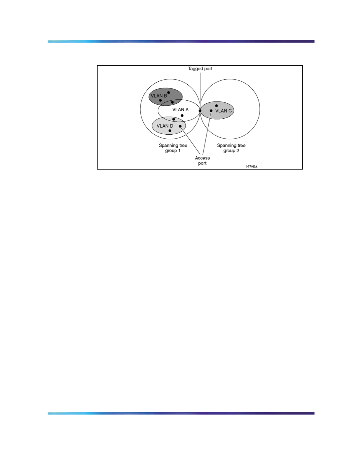
Multiple STGs are possible within the same switch; that is, the routing switch
can participate in the negotiation for multiple spanning trees.
Figure 4 "Multiple spanning tree groups" (page 27) shows multiple spanning
tree groups.
Nortel Ethernet Routing Switch 8300
Configuration — VLANs, Spanning Tree, and Static Link Aggregation using Device Manager
NN46200-510 03.01 Standard
4.0 27 August 2007
Copyright © 2005-2007, Nortel Networks
.
Spanning Tree Protocol (STP) 27
Figure 4
Multiple spanning tree groups
Spanning Tree Protocol controls
The ports associated with a VLAN and VLANs themselves must be
contained within a single STG to prevents problems with spanning tree
blocking ports and loss of connectivity within the VLAN.
Each untagged port can belong only one STG, while tagged ports can
belong to more than one STG. When a tagged port belongs to more than
one STG, the spanning tree bridge protocol data units (BPDUs) are tagged
to distinguish those of one STG from those of another STG. BPDUs from
STG 1 are not tagged. The tagged BPDUs are transmitted using a multicast
MAC address as tagged frames with a VLAN ID. Because tagged BPDUs
are not part of the IEEE 802.1D standard, not all devices can interpret
tagged BPDUs.
You can enable or disable the Spanning Tree Protocol at the port or at the
spanning tree group level. If you disable the protocol at the group level,
received BPDUs are handled like a MAC-level multicast and flooded out the
other ports of the STG. Note that an STG can contain one or more VLANs.
Remember that MAC broadcasts are flooded out on all ports of a VLAN; a
BPDU is a MAC-level message, but the BPDU is flooded out all ports on
the STG, which can encompass many VLANs.
When STP is globally enabled on the STG, BPDU handling depends on
the STP setting of the port:
•
When STP is enabled on the port, received BPDUs are processed in
accordance with STP.
•
When STP is disabled on the port, the port stays in a forwarding state,
received BPDUs are dropped and not processed, and no BPDU is
generated.
Nortel Ethernet Routing Switch 8300
Configuration — VLANs, Spanning Tree, and Static Link Aggregation using Device Manager
NN46200-510 03.01 Standard
4.0 27 August 2007
Copyright © 2005-2007, Nortel Networks
.

28 VLANs, Spanning Tree, and Static Link Aggregation
Spanning Tree modes
ERS 8300 software release 2.2 introduces a Cisco-compatible Spanning
Tree mode. By default, the Nortel STG (NTSTG) is enabled, and all
BPDUs are sent on every MLT link. To use the Cisco-compatible Spanning
Tree mode, disable NTSTG — BPDUs are sent on only one link of the
aggregation group. See "Adding a link aggregation group" (page 110) for
configuration instructions.
Spanning Tree FastStart
When enabled on a port with no other bridges, Spanning Tree FastStart
brings the port up more quickly following switch initialization or a spanning
tree change. The port goes through the normal blocking and learning states
before the forwarding state, but the hold times for these states is the bridge
hello timer (2 seconds by default) instead of the bridge forward delay timer
(15 seconds by default). Thus, if FastStart is enabled on a port using the
defaults of 2 seconds for Hello time and 15 seconds for Forward Delay
time, it goes into the forwarding state in 4 seconds, instead of the usual 30
seconds. If the port sees a BPDU, it reverts to regular behavior.
Instead of disabling STP on a port, Nortel recommends enabling FastStart
on the port as an alternative.
FastStart is intended for access ports where only one device is connected
to the switch (as in workstations with no other spanning tree devices). It
may not be desirable to wait the usual 30 to 35 seconds for spanning tree
initialization and bridge learning.
Use Spanning Tree FastStart with caution. This procedure is contrary
to that specified in the IEEE 802.1D standard for Spanning Tree Protocol
(STP), in which a port enters the blocking state following the initialization
of the bridging device or from the disabled state when the port is enabled
through configuration.
Understanding STGs and VLANs
A VLAN can include all the ports in a given STG and there can be multiple
VLANs in an STG, but a VLAN never has more ports than exist in the STG.
The recommended practice is to plan STGs and then create VLANs.
In the ERS 8300 default configuration, a single STG encompasses all the
ports in the switch. For most applications, this configuration is sufficient.
The default STG is assigned ID 1 (STG1).
If a VLAN spans multiple switches, it must be within the same STG across
all switches; that is, the ID of the STG in which it is defined must be the
same across all devices.
Nortel Ethernet Routing Switch 8300
Configuration — VLANs, Spanning Tree, and Static Link Aggregation using Device Manager
NN46200-510 03.01 Standard
4.0 27 August 2007
Copyright © 2005-2007, Nortel Networks
.
Static link aggregation 29
Spanning Tree Protocol topology change detection
Change detection enables the detection of topology changes and sends a
topology change notification (TCN) to the Root, on an individual port basis.
Change detection is enabled by default. When change detection is enabled
and a topology change occurs, a trap is sent containing the following
information so that you can identify the device:
•
the MAC address of the STG sending the TCN
•
the port number
•
the STG ID
You can disable change detection on ports where a single end station is
connected, and where powering that end station on and off triggers the
TCN. Change detection is referenced in IEEE STD 802.1D.
Topology change detection configuration rules
The following rules apply to the Spanning Tree topology change detection
setting.
Table 4
Spanning Tree Protocol topology change detection configuration rules
•
You can configure change detection on access ports only. This also applies to link aggregation
ports.
•
If you disable change detection and then change the port from access to tagging-enabled,
the switch automatically sets change-detection to enabled for the port. This also applies to
link aggregation ports.
•
In a link aggregation group with access ports, modifications to change detection for a member
port are automatically applied to the remaining member ports.
Static link aggregation
Link aggregation is a point-to-point connection that aggregates multiple
ports so that they logically act like a single port with the aggregated
bandwidth. Grouping multiple ports into a logical link provides higher
aggregate throughput on a switch-to-switch or switch-to-server application.
Link aggregation provides media and module redundancy.
The ERS 8300 supports link aggregation in a static configuration mode
where no LACP is used. The ERS 8300 link aggregation is interoperable
with Baystack and Ethernet Routing Switch 8600 link aggregation, also
referred to as MLT.
This section includes the following topics:
• "Link aggregation traffic distribution" (page 30)
•
"Link aggregation rules" (page 30)
•
"Link aggregation examples" (page 31)
Nortel Ethernet Routing Switch 8300
Configuration — VLANs, Spanning Tree, and Static Link Aggregation using Device Manager
NN46200-510 03.01 Standard
4.0 27 August 2007
Copyright © 2005-2007, Nortel Networks
.

30 VLANs, Spanning Tree, and Static Link Aggregation
Link aggregation traffic distribution
Static aggregation groups can be used to aggregate bandwidth between
two switches. The ERS 8300 distributes traffic by determining the active
port in a link aggregation group that can be used for each outgoing packet.
Link aggregation group algorithms provide load sharing while ensuring that
packets do not arrive out of sequence.
The ERS 8300 determines the port a packet is transmitted through by:
• Tabulating the trunks and their active assigned port members for each
link aggregation group. Ports defined as trunk members are written to
the table in the order in which they are activated. If a link goes down, the
table is rewritten with one less trunk member.
•
Using a selected index, based on traffic type and a hashing algorithm.
Packet distribution methods
Table 5 "Methods of traffic distribution for packets with a trunk destination"
(page 30) shows the methods used, by type of packet, to distribute packets
with a trunk destination.
Table 5
Methods of traffic distribution for packets with a trunk destination
Type of packet
MAC
source
address
(SA)
MAC
destination
address (DA)
IPv4
source IP
address
(SIP)
IPv4
destination
IP address
(DIP)
Layer 3
protocol
Bridged packet X X
Bridged packetwith
Layer 3 trunk load
balancing
XX
Routed packet X X X
Trunk load sharing algorithms by traffic type
For information about hashing parameters and algorithms that are used for
distributing link aggregation traffic, see Nortel Ethernet Routing Switch 8300
Planning and Engineering—Network Design Guidelines (NN46200-200).
Link aggregation rules
This section describes the rules for the link aggregation groups in the ERS
8300 ..
•
Link aggregation is supported on 10BASE-T, 100BASE-TX,
100Base-FX, Gigabit Ethernet ports, and 10Gigabit Ethernet ports.
• The switch supports eight ports per aggregation group. All ports in a
link aggregation group must be of the same media type and have the
same speed and duplex settings.
Nortel Ethernet Routing Switch 8300
Configuration — VLANs, Spanning Tree, and Static Link Aggregation using Device Manager
NN46200-510 03.01 Standard
4.0 27 August 2007
Copyright © 2005-2007, Nortel Networks
.
 Loading...