

Nortel Meridian Companion, Meridian Companion 1, Meridian Companion SL Maintenance Manual

NOTICE: Notwithstanding any explicit confidentiality or proprietary markings to the contrary, the
information contained in this document has been reviewed and approved for public disclosure
by Nortel. However, the access to, use and disclosure of this document and the information
contained therein continue to be subject to copyright and other restrictions, conditions and
limitations as detailed in the Terms of Use. (http://www.nortel.com/help/legal/index.html)
Meridia n 1
Meridian Companion
Installation and Maintenance Guide
Document Number: 553-3601-220
Document Release: Standard 4.00
Date: November 1998
Copyright @ 1996—1999 Nortel Networks, All Rights Reserved
Printed in Canada
The information contained herei n is the p roperty of Nortel Netw orks and is strictly confidential. Ex cept as
expressly authorized in writing by Nortel Networks, the holder shall keep all information contained herein
confidential, shall disclose the information only to its employees wit h a need to know, and shall protec t the
information, in whole or in part, from disclosure and dissemination to third parties with the same degree of
care it uses to protect its own confidential information, but with no less than reasonable care. Except as
expressly authorized in writing by Nortel Networks, the holder is granted no rights to use the information
contained herein.
Meridian 1, S L-1, and Compan ion are trademar ks of Nortel Networks Corporation. Windows 3.1 and
Windows 95 are trademarks of Microsoft.
NORTEL NETWORKS CONFIDENTIAL


Contents
Introduction to Meridian Companion...............................1
Preparing to install a Meridian Companion system........................1
Installing a Meridian Companion system........................................2
Installation warnings.......................................................................3
Safety precautions..........................................................................6
System overview ..........................................................................10
Installing the hardware....................................................11
Page iii of x
Installing Base Stations................................................................12
Installation guid e li n e s............................................. ...................... ..............12
Powering a Base Station ............................................................................13
Mounting a Base Station ............................................................................14
Installing remote power interconnect units . ................................................16
Mounting the remote power interconnect unit............................................. 24
Wiring the RPI unit...................................................................................... 26
Upgrading an RPI-8 to an RPI-16 ...............................................................31
Mounting a Base Station plug-top power supply ........................................32
Installing external antennas and lightning surge arrestors...........35
Installing an indoor directional external antenna ........................................36
Installing an indoor omnidirectional external antenna ................................37
Meridian Companion Inst allation and Maintenance Guide

Page iv of x
Installing a Companion Administration Terminal..........................42
Installing Companion Manager....................................................43
Installing the PC Interface Card...................................................43
Installing a Remote Access Device..............................................47
RAD configuration options...........................................................48
Installing an outdoor omnidirectional external antenna...............................39
Installing the lightning surge arrestor..........................................................41
Installing the Administration Term inal..........................................................42
Mounting an Administration Terminal on the wall........................................43
Setting the base address dip switches........................................................44
Installing the PCI card.................................................................................46
Setting the hardware interrupt .....................................................................46
Wiring the Time Compression Multiplexing lines .........................51
Planning the IPE and CE/PE Module wiring ...............................................51
Installing Meridian Companion cards...........................................59
Normal LED behavior upon installation.......................................................60
Placing the cards.........................................................................................62
Installing the cards......................................................................................66
System initialization........................................................69
Verifying initialization....................................................................69
Are arrow indicators flashing? .....................................................................69
Do you see Select Country?.......................................................................69
Did you install more Base Stations? ........................................................... 70
Do you see
Does the display show this message? . . ......................................................71
Memory Reset .............................................................................71
Re-Eval required
?............................................................70
Programming the Meridian Companion system...........73
The Meridian Companion Programming and Provisioning Record............. 74
553-3601-220 Standard 4.00 November 1998

Page v of x
The Administration Terminal.......................................................................74
Buttons ....................................................................................................... 74
Operating the Administration Terminal......................................... 76
Choosing Administration Ter m inal lan guages ............................................76
Adjusting the contrast................................................................................. 77
Entering a Configuration programming session ......................................... 77
Entering an Administration session............................................................ 77
Ending a programming session.................................................................. 78
Recording and reporting alarm messages .................................. 78
Verifying card status .................................................................... 79
Verifying Base Station status....................................................... 80
Programming telephony data....................................................... 81
Dial delay.................................................................................................... 81
B03 gain value modification........................................................................ 82
P ortable telephone side tone................................................... ...................83
CMCC slot........ ............... ..................... ............................ ...................... .... 84
Dual tone multifrequency timing............................................ ....... .. .......... .. 85
Pulse code modulation mode ..................................................................... 85
WTN ........................................................................................................... 86
Programming mobility data.......................................................... 87
Setting the antenna type for a radio ...........................................................87
Setting the System Access Logical Identifier .............................................. 88
Programming the system time and date...................................... 90
Programming the system time.................................................................... 90
Programming the system date.................................................................... 91
Changing pass w ords........................................... ......... ......... ...... 92
Changing the Installer password............................................. ....... ..... .......92
Changing the Administration password. ..................................................... 93
Changing the Registration password.......................................................... 94
Activating wireless communication .............................. 97
Meridian Companion Inst allation and Maintenance Guide

Page vi of x
Activating a new system...............................................................97
Verifying a Meridia n Comp an io n instal lat ion. ..... ..... .....99
Viewing radio and cell assignments. .........................................................100
Identifying a radio’s cell assignment .........................................................101
Configuring the Meridian 1 for the Meridian Companion system
103
X11 release 15 or greater without package 240 ........................104
X11 release 20B or greater with package 240........................... 105
Wireless telephone privacy........................................................ 107
Programming options................................................................. 107
X11 release 24 with package 350, feature MC32......................110
Programming user options.. .... ..... ..... .............. ..... ..... ...11 5
Programming Call Transfer on Radio Loss ................................115
Programming a system default for radio loss handling .............. 116
Programming individual Transfer on Radio Loss........................116
Register ing an d verif yin g por t able te lep hon es ..........119
Enabling and disabling registration............................................120
Locking Registration on (optional)............................................................. 1 20
Registering portable telephones................................................121
Verifying a portable telephone’s operation.................................121
Verifying the WTN .....................................................................................121
Verifying the portable can make or receive calls....................................... 1 21
Option al ch ecks............................ ...................... ............................ ...........122
553-3601-220 Standard 4.00 November 1998

Page vii of x
Deregistering the WTN.............................................................. 122
Maintenance................................................................... 123
Using maintenance commands ................................................. 123
Meridian 1 card maintenance................................................................... 124
Administration Terminal maintenance commands.................................... 125
Maintenance features ................................................................ 125
System Stat u s.......................... ............................ ...................... .............. 126
Card Status ... ....... ............................ ...................... ............................ ..... 128
Wireless Terminal Number (WTN) Status ................................................ 130
TCM Status ................. ............................. ..................... .......................... 132
Event/Alarm log........................................................................................ 134
Entering the Event/Alarm log ................................................................... 135
Checking the most recent alarm .............................................................. 1 35
Checking when an alarm or event occurred............................................. 1 35
Checking consecutive repetitions of an alarm or event . ........................... 136
Erasing the log ......................................................................................... 136
Administration log..................................................................................... 1 37
Entering the Administration log ................................................................ 137
Checking when an event occurred ........................................................... 138
Checking the most recent alarm .............................................................. 1 38
Checking consecutive repetitions of an event or alarm . ........................... 138
Erasing the Administration log ................................................................. 139
Responding to event and alarm messages ............................... 139
Responding to an alarm code .................................................................. 139
System Reevaluation................................................................. 140
Scheduling System Reevaluation............................................................. 143
Replacing equipment................................................................. 145
Adding or moving Base Stations .............................................................. 1 45
Replacing a defective Base Station.......................................................... 147
Adding expansion cards........................................................................... 1 48
Optimizing Card Slot Usage.....................................................................150
Relocating the system.............................................................................. 151
Replacing a defective expansion card...................................................... 1 54
Meridian Companion Inst allation and Maintenance Guide

Page vi ii o f x
Replacing a defective ROM card...............................................................155
Replacing a defective CMCC....................................................................158
Replacing a defective remote power interconnect unit. .............................158
Replacing a defective Remote Access Device..........................................160
Replacing a defective Administration Terminal..........................................160
Replacing a portable..................................................................160
Handling Meridian Companion exceptions ................................160
Config warning: Recoverable inconsistency.............................................. 1 61
Config failure: Nonrecoverable inconsistency ...........................................1 61
Config ambiguous .....................................................................................162
Troubleshoot ing.................... .........................................163
General troubleshooting procedures..........................................163
Troubleshooting power problems ...............................................165
Troubleshooting cards................................................................ 165
Normal card LED behavior........................................................................166
Troubleshooting the Administration Terminal .............................168
Troubleshooting a Base Station .................................................169
Troubleshooting a remote power interconnect unit ....................170
Troubleshooting portable telephone problems...........................172
Troubleshooting a RAD..............................................................173
Troubleshooting an alarm...........................................................174
Understanding event messages.................................................179
Appendix A: Programming overview...........................183
Appendix B: Regulatory information...........................185
553-3601-220 Standard 4.00 November 1998

Page ix of x
Registration........... ......... .......... ......... ......... .......... ...................... 185
Safety........... ......... ......... .......... ......... ......... .......... ......... ............. 185
Equipment attachment limitations.............. .......... ......... ......... .... 187
Telecom compliance .................................................................. 188
Telephone company notification ................................................ 188
Rights of the telephone company .............................................. 188
Interf er ence causing equipm ent ................................... ......... .... 189
Load Number............................................................................. 189
Repair facility ............................................................................. 189
Note for hearing aid users ......................................................... 189
Privacy....................................................................................... 190
List of terms........................ ..... ..... ..... ..... .... ..... .............. 191
Meridian Companion Inst allation and Maintenance Guide

Page x of x
553-3601-220 Standard 4.00 November 1998

Introduction to Meridian Companion
The Meridian Comp anion application integrates wireless telephone capability
into a Meridian 1 syste m. Meridian Companion us es radio technology to
transmit and receive signals between portable (wireless) telephones and Base
Stations connected to a Meridian 1 s ystem.
Preparing to install a Meridian Companion system
Before usin g this guide, read M er idian Companion Product Overview .
The follow ing must be completed before installing the Meridian Companion
system:
❏ site plan ning (the proce ss of determini ng the loca tion and number of B ase
Stations required at a customer site)
❏ installation of the wiring required for the Base Stations
Page 1 of 206
❏ installation of AC power for a plug-top power supply to power each Base
Station or for a remote power interconnect (RPI) unit to power multiple
Base Sta tions
❏ installation of primary protectors for Base Stati ons in application s with
exte rnal exposed wiring a nd provis ioning for placement of the secondary
protect ors, as needed
❏ for an ST/STE, RT, NT, or XT system, an upgrade so that the system has
an IPE Module or a CE/PE Modul e
Meridian Companion Inst allation and Maintenance Guide

Page 2 of 206 Introduction to Meridian Compani on
❏ preparat ion of the IPE Module or CE/PE Module to ens ure the
following:
— availa bility of sufficient contiguous slots for Meridian Companion
cards (Option 11 may require an expansion cabi net)
— placement of all power and main distribution frame (MDF) cables
Information derived duri ng the site planning process is entered in Meridian
Companion Programming and Provisioning Record. Installation requires a
copy of thi s document plus the annot ated si te floor pl ans that were used duri ng
site planning. Check this record to make sure that all equip me nt and supplies
are availa b le .
Meridian Compani on Site Planning Reference Manual describ es these
preinstallation steps .
Installing a Meridian Companion system
Installing a Meridian Companion system involves the following:
• installing, wiring, and powering hardware components:
— Base Stations and any external antennas
— plug-top power supplies, where required
— RPI units, if used
— Remote Access Device (RAD)
— Administration Terminal, if used
• cross connecting Base Station Time Compression Multiplexing (TCM)
wires at t he main distrib ution frame (MDF) and inst alling an y seconda ry
protect ors needed for external exposed wiri ng
• connecting the RAD and setting up line for remote access
• atta ch ing the fe at ur e ROM ca rd to th e C om p anion M er i di an Co n t r ol ler
card (CMCC), and the n inst al ling the Compan ion e x pansi on cards in an
IPE or CE/PE M odu l e
553-3601-220 Standard 4.00 November 1998
Introd uction to Meridian Companion Page 3 of 206
• programming the Meridian Companion system (using the
Administration Terminal or Companion Manager), excluding user
options
• preparing a radio cell assignment list for Base Stations based on what
you observe during reevaluation
• verifying the mobility system and making correcti ons as necessary
• programming the Meridian 1 wireless terminal numbers (WTNs) and
enabl ing th e cards
• programming the user options in the Meridian Companion system
• regis tering and verifying individual user portables
• completing Meridian Companion Programming and Provisioning
Record
Companion Manager Installation and Operations Guide describes the
installation, operations, administration, and maintenanc e of Meri dian
Companion systems through Companion Man age r, a Microsoft Windo ws
®
application that runs on the Administration PC. You can use Companion
Manager instead of or in addition to the Administ ration Terminal.
Meridian Compani on Administrat ion Terminal Operations Guide describes
the programming and management of the portable telephones.
Installatio n warn in gs
Read this s ection carefully to ensure your safety and the safe ope ration of the
Meridian Compan ion system.
WARNING!
Do not connect the Administration Terminal,
Base Stations, or RAD directly to a central
office ( CO) li ne int er fa ce . Do ing so may resul t
in equipment damage.
Meridian Companion Inst allation and Maintenance Guide
Page 4 of 206 Introduction to Meridian Compani on
T o a void damage to equipmen t, do not insert
the plug at the free end of an Administration
Terminal cord directly into a wall or
baseboard outlet.
Check the lightning surge arrestors at the
cable ent ry point to the building and pay
special attent ion to the grounding.
Report any problems to the telephone
company in writi ng. Because Administ ration
Terminals , Base Stations, and RADs are not
lightning pr otected, do not inst all them outside
th e bu il d i n g.
WARNING!
SHOCK!
SHOCK!
To avoi d electrical sho ck hazard to personnel
or equipment, observe the following
precautions when installing telephone
equipment:
• Never install telephone wiring during a
lightning st orm.
• Never install telephone jac ks in wet
location s unless the jack is specificall y
designed for wet locations.
• Never touch noni nsulated telephone wires
or terminals unless t he tel ephone line has
been disconnect ed at the network
interface.
• Use caution when in stalling or modifying
the telephone lines.
553-3601-220 Standard 4.00 November 1998
Introd uction to Meridian Companion Page 5 of 206
CA UT ION!
To eliminate the possibility of accidental
damage to cords, plugs, jacks, and other
system components, do not use sharp
instruments during assembly procedures.
CAUTION!
Base Stations can be used off-prem ises only
with proper regul atory authority.
ATTENTION!
The Administration Terminal must not be used as off-p remises
equipment.
Meridian Companion Inst allation and Maintenance Guide
Page 6 of 206 Introduction to Meridian Compani on
Safety precautions
When using your telephone equipment , basic safety pre cautions shoul d always
be follo wed to reduce t he risk of fir e, elect ric shock, damage t o equipment , and
injury to per sons, inclu d ing the following:
Unplug the system from the AC outlet and
refer servicing to qualif ied service per sonnel
under the f ollowing conditions:
• when a power cord i s damaged or frayed
• if the equipment has been exposed to
WARNING!
rain, or liqu id has been spilled on any part
of it (if this hap pens , allo w the equipm ent
to dry out, unplugged, to see if it still
operates; do not disassemble the
equipment)
• if the housing of any part of the
equipment has been damaged
SHOCK!
To avoid fir e or electrical shoc k, do not
overl oad AC outlets and e xtension cor ds.
SHOCK!
To reduce the risk of electric shock, do not
disassemble the equipment. When any
service or repair work is required, contact a
qualified service person.
553-3601-220 Standard 4.00 November 1998

Introd uction to Meridian Companion Page 7 of 206
SHOCK!
Install an A C lightning sur ge arrestor in the A C
outlet that connects to the equipment .
Electrical surges, typically lightning
transi ents, are ve ry destruct ive to terminal
equipment connected to AC power sources.
WARNING!
Unplug the equipment from the AC outlet
befor e cleaning with a dam p cloth. Do not use
liquid or aeros ol cleaners.
CA UT ION!
Do not place any part of the equipment
• on an unstable cart, stand or table
• near or over a radiator or heat vent
• in an enclosure unless pr oper v entilat ion is
provide d
CA UTION!
Do not allow anything to rest on the power
cord.
Do not loc ate the equi pment where someone
may walk on the power cord.
Meridian Companion Inst allation and Maintenance Guide
Page 8 of 206 Introduction to Meridian Compani on
Never push objects of any kind into the
equipment slots.
Do not use any part of the equipment near
water.
Never spill liquids on the equipment.
CA UT ION!
WARNING!
WARNING!
Do not use any telephone in the vicinity of a
gas leak to report the leak.
CA UT ION!
Slots and openings in the cabinet and the
back or bott om ar e provi ded for ventilat ion. To
protect the equipment from ov erheating, do
not block or cover these openings.
CAUTION!
The equipment has a three-wire grounding
type plug with a third (grounding) pin. This
plug fits into a grounding type AC outlet only.
This is a safety feature. If you are unable to
insert the plug int o the A C outle t, c ont act y o ur
electrician to replace your obsolete AC outlet.
553-3601-220 Standard 4.00 November 1998

Introd uction to Meridian Companion Page 9 of 206
ATTENTION!
Heed the warnin gs and follow the inst ructions marked on the
Meridian Companion system.
Meridian Companion Inst allation and Maintenance Guide
Page 10 of 206 Introduction to Meridian Companion
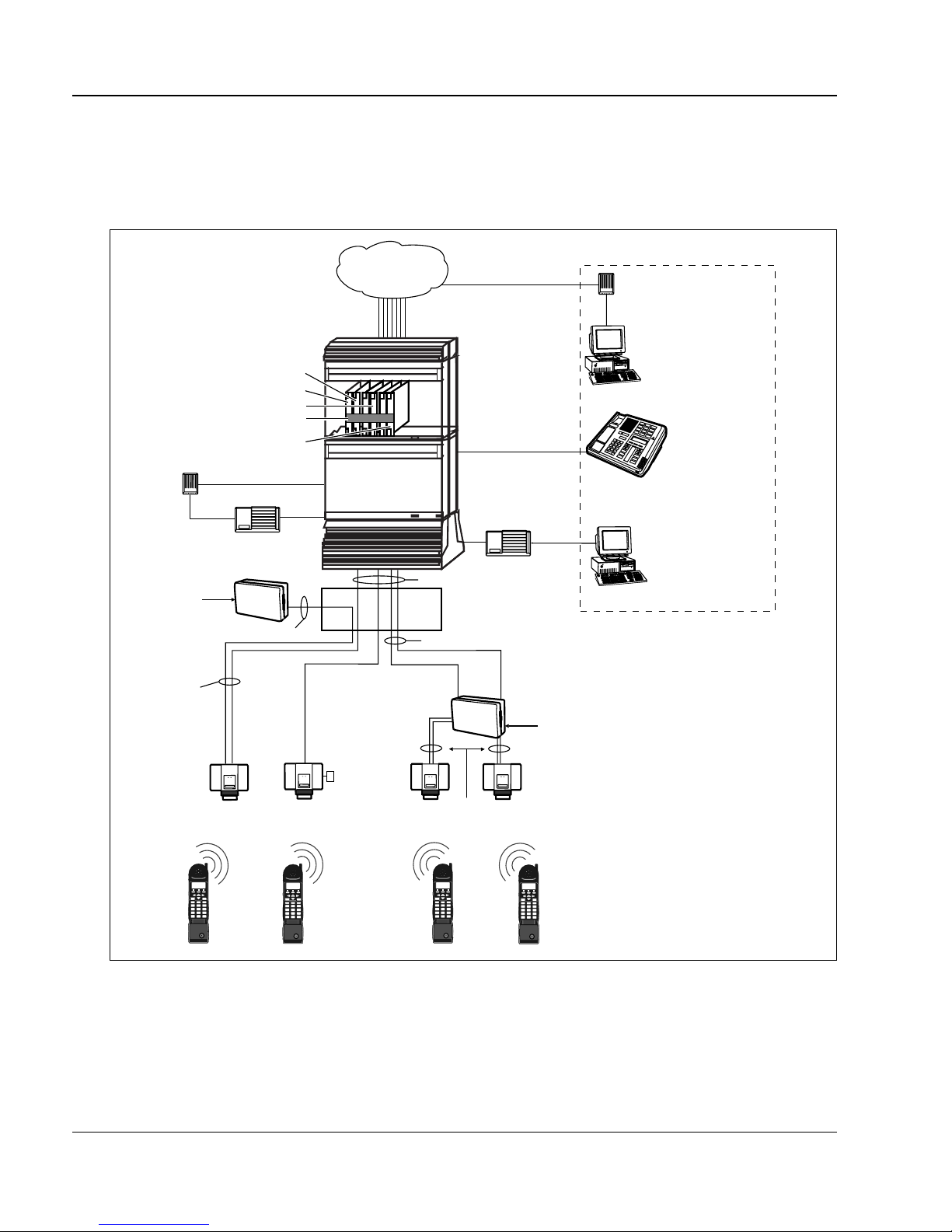
System overview
Figure 1 shows an overview of the Meridian Companion configuration.
Figure 1 : Meridian Companion overview
PSTN
access options
modem
modem
RS-232
AC power
1-pair (TCM)
and 1- or 2-pair
power to each
Base Station
digital CO trunks
CMRC
CMCC
CMBC
faceplate cable
CMLC
analog line
(DID access)
RAD 1
RPI at MDF
DC power
analog or
Base Stations
Meridian 1
MDF
Companion
Manager or
Companion
Diagnostic
N
Software
(remote access)
Administration
IPE module
}
PC
CO
M
PA
A
dm
N
IO
inistration
Term
inal
Terminal
(local access)
Companion
Manager or
RS-232
Companion
Diagnostic Software
TCM pairs
RAD 2
PC
and Meridian 1
maintenance
(local access)
1-pair (TCM) for each Base Station connected to a remote RPI
RPI
AC power
12
4
7
*
GHI5JKL6MNO
PRS8TUV9WXY
FeatureDir
System End
ABC3DEF
0#
FeatureDir
System End
portable telephones
ABC3DEF
12
GHI5JKL6MNO
4
PRS8TUV9WXY
7
0#
*
553-3601-220 Standard 4.00 November 1998
local
power
1- or 2-pair power for each Base Station connected to a remote RPI
12
GHI5JKL6MNO
4
PRS8TUV9WXY
7
*
FeatureDir
System End
ABC3DEF
0#
12
4
7
*
GHI5JKL6MNO
PRS8TUV9WXY
FeatureDir
System End
ABC3DEF
0#

Installing the hardware
This section includes information on installing a Meridian Com panion syste m.
Installation should proceed in the following order:
• insta ll Base Stations an d Base S tation plug-top power supplies
• install remote power int erconnect units
• insta ll external antennas and lightni ng surge arrestors
• insta ll a Companion Admin istration Terminal
• install a Remote Access Device
• wire the Time Compression Multiplexing (TCM) lines
• insta ll Meridian Companion cards
Note: If you plan to use Companion Manager instea d of or in addition to the
Administration Terminal, refer to Companion Manage r Installation and
Operations Guide.
Page 11 of 206
Meridian Companion Inst allation and Maintenance Guide

Page 12 of 206 Insta ll ing the hardware
Installing Base Stations
Before installing a Base Station, verify the position as documented in the
Meridian Compani on Programming and Provisioning Record.
Installatio n guidelines
Each Base Station must be installed within 1200 m (TCM
wiring length) of the Meridi an Com panion system.
Consider the following point s when installing Base Stations or Base Stat ion
plug-top power supplies:
• Ensure that the installation complies with your local electrical code.
ATTENTION!
• Install Base Stations indoors where there is no condensation and the
temperatur e r emains between 0°C and 50°C, preferably between 15° C
and 35°C.
• Instal l all Base St ations wit hin 1200 m (wiri ng length) of th e Meridian 1
system.
• Do not p ositi on Base S tations on la rge concrete o r ma rble colu mns. Base
Statio n s mu s t b e at lea st 1 m fr om such col u m n s. Lo c ate all Bas e
Stations at a cell center on the same side of such columns.
• Position Base Stations on ceilings, or upright against wall s cl ose to the
ceilin g on s u rfac es with th e s ame mate r ial compo s i ti o n .
• Allow a clearance o f at least 9 cm between the Ba se Stations and
surroundi ng objects, excluding other Base Stations (see Figure 2 on
page 14).
• Pos i ti o n al l th e Base Stations at the sa me cell center a maximum o f
1.5 m apart, with a minimu m of 9 cm between the Bas e Station s ( see
Figure 2 on page 14).
• Do not position Base Stations in ducts, plenums, o r hollow spa ces used
to transport environmental air.
553-3601-220 Standard 4.00 November 1998

Installing the hardware Page 13 of 206
• Position Base Sta tions away from where a port able is used in an office
area b y at lea st the amount sho wn in Table 1. Installing the Base Stati ons
on ceil ing s or h igh on wal ls he lps t o m aint ain thes e mi nimum di stanc es.
Table 1 : Minimum distance between office areas and Base Stations
Number of Base Stations
in the cell
11 m
21.4 m
31.8 m
42 m
Minimum distance between
office areas and Base Stations
• If powering with plug-top power, position the Base Station within 4 m
of an AC outlet, since the plug-top power supply has a 4-metre cord.
Keep these points in mind:
— the power supply must be lo cated in an area acces sible to a prope rly
grounded AC outlet
— the input plug is part of the po wer supply (the only way to remove
power is to disconnect the power supply)
— if you must install a new AC outlet to accommodate the power
supply, ensure that the AC outlet is mounted with sufficient
clearance to plug the power supply
Powering a Base Station
Base Stations can be powered by plug-top power supplies or remote powe r
interconn ect units. See “Insta lling remote powe r interconnect units” or
“Mounting a Base Station plug-top power supply” for your configuration.
— if more than one Bas e Stat ion is in st alle d at a cell cen ter, ens ur e that
each plug-top power supply has a separate AC outlet
Meridian Companion Inst allation and Maintenance Guide
Page 14 of 206 Insta ll ing the hardware
Mounting a Base Station
Base Stations can be mounted on a wall or on a ceiling (when mounting on a
wall, i nstall it with the cover at t he bottom, as s hown in F igure 9 on pag e 21).
Allow for the following clearance around the Base Station.
Figure 2 : Clearance for the Base Station
9 cm from
other objects
cover
9 cm from
other objects
Base Station
bracket mounting
screw hole
27 cm
center
41 cm
bracket mounting
screw hole
Bracket
Mounting a Base Station
1. Fasten the bracket into position usi ng two 4 mm screws.
2. Route th e telep hone cable from the distrib ution bl ock th rough the t op (or
bottom) ope ning.
3. Wind any excess telephone cable around the posts to secure it, then
fasten it under th e strain relief.
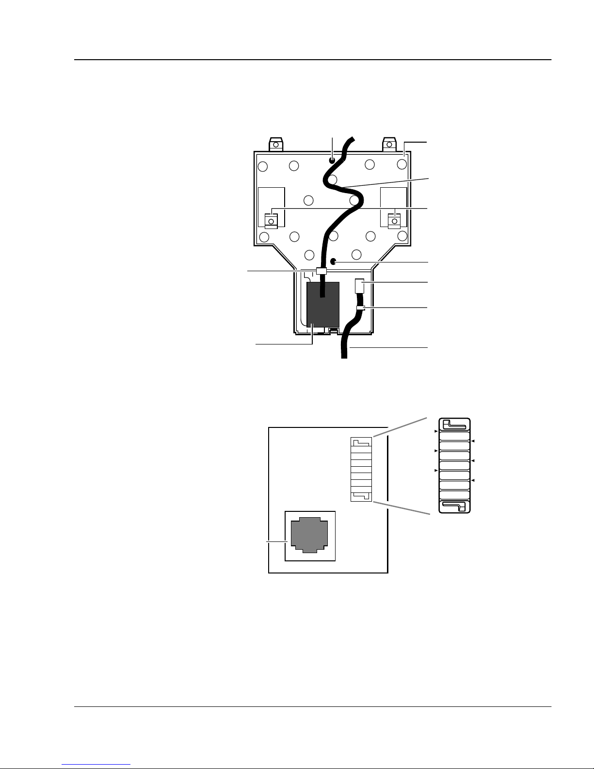
4. Connect the cable wires to the BIX connector on the termination board
as shown in Figure 4 on page 15.
553-3601-220 Standard 4.00 November 1998
Installing the hardware Page 15 of 206
Figure 3 : Base Station mounti ng bracket detail
bracket mounting
screw hole
strain relief tab
Base Station
mounting
bracket
telephone
line cord
Base Station
mounting
clips
bracket mounting
screw hole
power supply connector
strain relief tab
Base Station
termination
board
power supply cord
Figure 4 : Terminati on board
TCM
-PWR(1)
-PWR(2)
RJ11 jack
TCM
+PWR(1)
+PWR(2)
5. Mount the Bas e Station onto the bracket, snapping it into position.
6. Connect the power RJ11 jumper lead to the RJ11 jacks on the
termination board and the Base Stat ion.
Meridian Companion Inst allation and Maintenance Guide
Page 16 of 206 Insta ll ing the hardware
7. Record the associated port number in the s pace provided on the printed
label affix ed on the lower right corner of the mounting bracket.
Note: Include th e la beling information for each Base Station on the
comple ted i nsta lla tion f loor pla ns and the Mer idian Companion
Programming and Provisioning Record for reference.
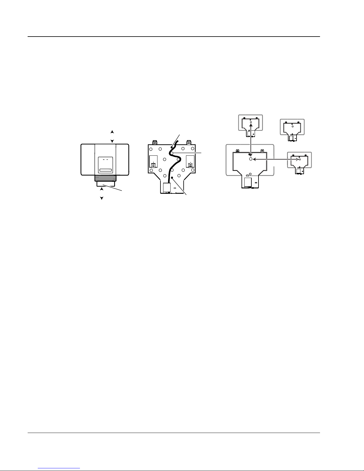
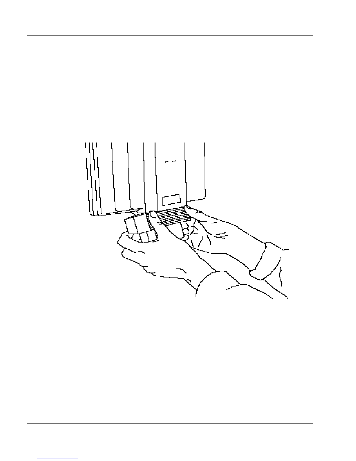
8. Slide the c over onto the br acket, using t he guide to position it properly.
Snap the cover into place.
Figure 5 : Sliding cover onto bracket
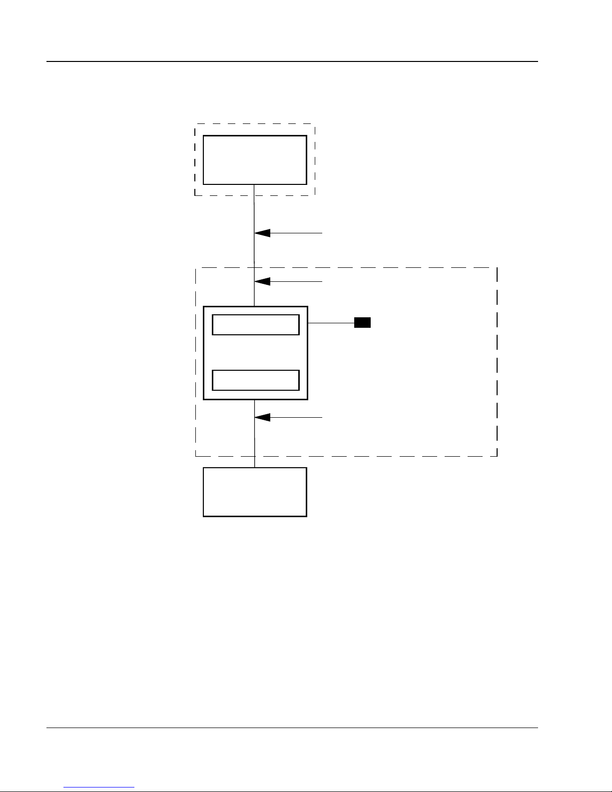
Installing remote power interconnect units
Figures 6 and 7 illustrate two possible configur ation options using a remote
power interconnect (RPI) unit.
Figure 6 shows a configuration that is appropriate for a small installation
where ther e is no main distribution f rame (MDF). In this case, the RP I MDF
capabili ties provid e the connections between the Meridian 1 system, Base
Station power, and Base Stations. Essentially, the RPI unit functions as a
distribution panel. This configuration can also be used if the existing MDF is
553-3601-220 Standard 4.00 November 1998
Installing the hardware Page 17 of 206
full or if the customer wants to keep the wiring separate from the other
telephone set wiring.
Note: The polarity of the TCM connections is not important. If two power
pairs ar e brought in, they must be connected with the same polarity to
the termina tion board.
WARNING!
When using two po wer pairs, ensure
they are connect ed w ith the same
polarity.
Meridian Companion Inst allation and Maintenance Guide
Page 18 of 206 Insta ll ing the hardware
Figure 6 : Base Station powering: RPI configuration option 1
CMCC, CMRC or CMBC
Meridian 1
TCM cable
RPI
1-pair TCM wires per
Base Station input to RPI
input
main power
RPI
output
Base Stations
1-pair TCM and 1- or 2- power pairs
wires per Base Station output
from RPI
553-3601-220 Standard 4.00 November 1998
Installing the hardware Page 19 of 206
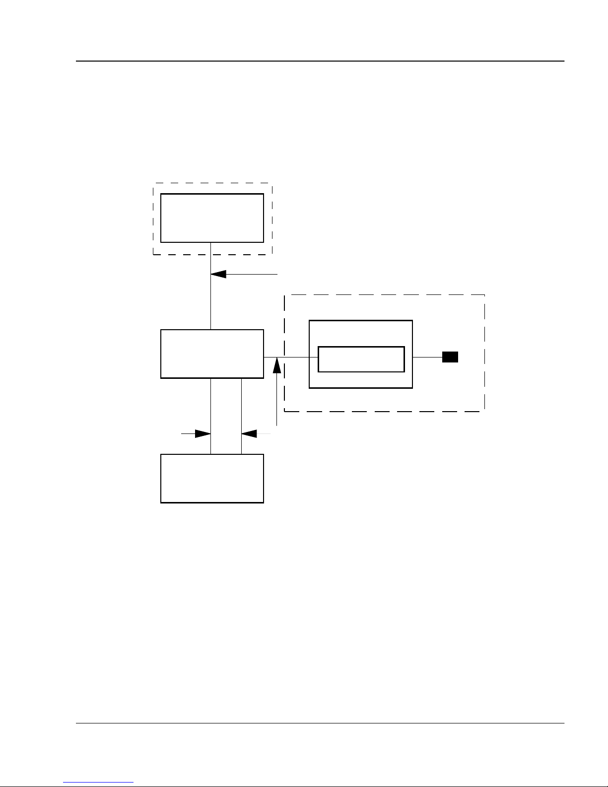
Figure 7 shows a config urat ion that wou ld be su itabl e for a syst em that ha s an
exist ing MDF. Typically the MDF is loca ted in the same room as th e
Meridian 1 system, although it could be a cl oset MDF. In either case the Base
Stations are wire d through the MDF rather than the RPI unit.
Figure 7 : Base Station powering: RPI configuration option 2
Meridian 1
CMCC, CMRC or CMBC
TCM cable
RPI
RPI
1-pair TCM wires
per Base Station
MDF
1- or 2- power pairs per Base Station
Base Stations
output
main power
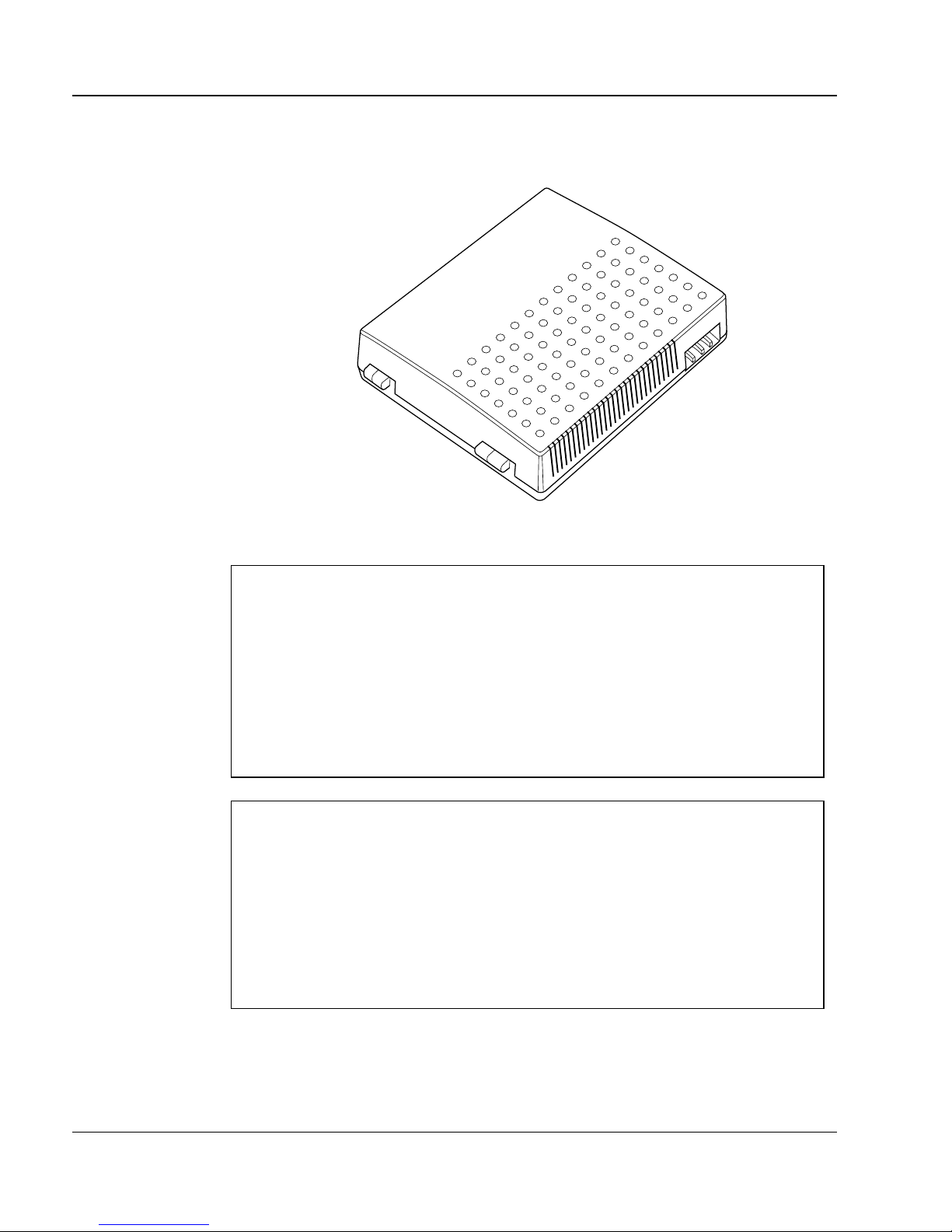
An illustration of an RPI unit appears in Figure 8. Figure 9 illustrates RPI
components.
Meridian Companion Inst allation and Maintenance Guide
Page 20 of 206 Insta ll ing the hardware
Figure 8 : RPI unit
ATTENTION!
The RPI unit should have the dc backup power supplied by
a UL listed UPS.
The UPS should have an output voltage rating of 44 to 50 V dc,
with a maximum fault current limit of 6 A to protect the RPI’s
output wiring. Otherwise, it may be necessary to use class 1
wiring.
ATTENTION!
The RPI units must always be installed in side a building.
The AC outl et pow erin g the RPI unit sh oul d be insta lled ne ar the
equipment and shoul d be easily accessible.
The length of t he RPI c ord , fr om the o uts ide su rf ace of t he unit to
the plug, should be a mini m um of 2 m and a maximum of 4.5 m.
553-3601-220 Standard 4.00 November 1998
 Loading...