

Nortel Meridian Companion PCI User Manual

Companion Diagnostic Software
for PCI User Guide


Companion Diagnostic Software
for PCI User Guide
P0886303
Issue 01 Standard
November 1998
© 1998 Northern Telecom
All rights reserved
Printed in the United States of America
Companion is a trademark of Northern Telecom.


P0886303 Issue 01 Standard Companion Diagnostic Software for PCI User Guide 1
Contents
Companion Diagnostic Software basics 5
CDS package checklist 6
Equipment checklist 6
Local access equipment 7
Remote access equipment using the RAD internal modem 7
Remote access equipment using a RAD external modem 8
Optional equipment 8
Connect the equipment 8
Local access connections 9
To connect the PC to the RAD 9
Remote access connections using the RAD internal modem 11
Remote access connections using a RAD external modem 13
Wireless system programming 15
Local access programming 16
Remote access programming using the RAD internal modem 16
Remote access programming using a RAD external modem 17
Make a working copy 17
Installing and using CDS on your hard drive 17
Using CDS from your floppy drive 18
Files needed by CDS 18
Site administration 19

2
Companion Diagnostic Software for PCI User Guide P0886303 Issue 01 Standard
Setting up CDS for a new site 20
Local access 20
Remote access 22
Files created by setting up a new site 24
Changing the administration data of an existing site 24
Local access 25
Remote access 27
Using Companion Diagnostic Software 31
Selecting data 34
Automatic system configuration 35
Exiting CDS 36
Display screen components 37
A Typical CDS Session 38
Keyboard functions 39
Making menu selections 40
Files created when using CDS 40
Display screens 41
Command map 42
Main menu 43
Diagnosis Option 43
Monitor Option 44
Utilities Option 44
Diagnosis 45
Automatic System Diagnosis 45
Diagnosis Menu Options 49
Quality of Service 50
Quality of Service components 52
System Faults components 57
Radio Signals 64
Cell Signals 69
Interference 72
Traffic 74

3
P0886303 Issue 01 Standard Companion Diagnostic Software for PCI User Guide
Monitor 82
Background RSSI 83
Reset RIM 86
Query BS Faults 89
Clear BS Faults 91
Clear Counters 92
Utilities 94
View System Configuration 95
Create Dataset 96
Delete Dataset 97
Appendix A 99
Equipment requirements 100
CDS software 100
PC 100
RAD 101
PC modem 101
RAD external modem 101
RS232 cable 102
RAD TCM cable 102
RS232 null modem cable 102
Public switch line cable 103
PC modem initialization string 103
Appendix B 105
Diagnosis Action Recommendations 106
How to report a problem 106
System Faults 106
Traffic 114
Interference 117
Radio Signals 118
Appendix C 121
CDS Error Messages 122
Appendix D 125
RUNCDS: Running CDS in Batch Mode 126
RUNCDS Command Line Syntax 128
The CDS Macro Language 129

4
Companion Diagnostic Software for PCI User Guide P0886303 Issue 01 Standard
Macro Language Rules 129
CDS Macro Language Commands 129
Examples 132
Appendix E 137
CDS DOS Hard Drive Disk File Management 138
Files needed by CDS 138
Files created by administering a new site 138
Files created when using CDS 139
Saved Datasets 140
DOS File Summary 143
Index 145

P0886303 Issue 01 Standard Companion Diagnostic Software for PCI User Guide 5
Companion Diagnostic Software basics
• Introduction
• Checklists
• Connections
• Modem Access
• Installing CDS

6 Companion Diagnostic Software basics
Companion Diagnostic Software for PCI User Guide P0886303 Issue 01 Standard
About Companion Diagnostic Software for PCI
Companion Diagnostic Software (CDS) for Personal
Communications Interface (PCI) allows you to examine the
operating characteristics of a wireless system while the system is
operating at a customer site. The CDS application runs on a personal
computer (PC). You can use it locally at the customer site or
remotely from another location. When you use remote access, the
PC interfaces with the wireless system indirectly via mode ms. When
you use local access, the PC interfaces with the wireless system
directly without modems. CDS performs automatic system
configuration and automatic system diagnosis. It also presents on
your PC screen data derived from wireless operation. The displays
contain various le vels of detail and are in the form of bar charts and
statistical tables, with accompanying commentaries.
The two radio transce ivers in a Base Station opera te in a n al located
frequency spectrum. Base Stations are grouped into cells, a cell may
have two or more radios in it depending upon the number of Base
Stations making up the cell. These cells overlap each other to ensure
continuous radio coverage throughout the desired coverage area. In
each cell, at any one time, one radio may be used to provide a
common signalling channel (CSC) which locates and tracks portable
movements. Companion Diagnostic Software provides access to
information on the operating characteristics of both regular traffic
and CSC radios.
CDS package checklist
The CDS package includes the following:
• high density 3 1/2" CDS diskette
• Companion Diagnostic Software for PCI User Guide
Equipment checklist
The following is a checklist of equipment requirements for each type
of connection. For more detailed descriptions of the equipment
required, see Appendix A of this guide.

Companion Diagnostic Software basics 7
P0886303 Issue 01 Standard Companion Diagnostic Software for PCI User Guide
Local access equipment
To install and use CDS with local access, you must have the
following:
• Remote Access Device (RAD)
• RAD Time Compression Multiplexing (TCM) cable, to connect
the RAD to the Controller
• IBM compatible PC (386 processor or greater)
• RS232 cable, to connect the PC to the RAD
Remote access equipment using the RAD internal modem
To install and use CDS with remote access via the RAD internal
modem, you must have the following:
•RAD
• RAD TCM cable, to connect the RAD to the Controller
• IBM compatible PC (386 processor or greater)
• PC modem
• RS232 cable, to connect the PC to the PC modem
• Public switch line cable, to connect the PC modem to the public
switch

8 Companion Diagnostic Software basics
Companion Diagnostic Software for PCI User Guide P0886303 Issue 01 Standard
Remote access equipment using a RAD external modem
To install and use CDS with remote access via the RAD external
modem, you must have the following:
•RAD
• RAD TCM cable, 32 in (80 cm), to connect the RAD to the
Controller
• IBM compatible PC (386 processor or greater)
• PC modem
• RS232 cable, to connect the PC to the PC modem
• Public switch line cable, to connect the PC modem to the public
switch
• RAD external modem
• RS232 null modem cable, to connect the RAD to the RAD
external modem
Optional equipment
You may want to have the following hardware:
• high density 3 1/2" diskette to make a working copy of the
application
• hard drive for storing large amounts of data
• portable computer with battery power supply f or greater mobility
Connect the equipment
You can make two types of equipment connections to examine
wireless system operation using CDS. A local access connection
may be made using an R S232 cable at the customer site, or a remote
connection may be made through a PC modem to use CDS at a
location other than the customer site.
Note:
The RAD cannot be programmed if an RS232 cable is
connected to its serial port. Ensure that the required RAD
programming has been done before connecting the RS232
cable to the RAD serial port.
Companion Diagnostic Software basics 9
P0886303 Issue 01 Standard Companion Diagnostic Software for PCI User Guide
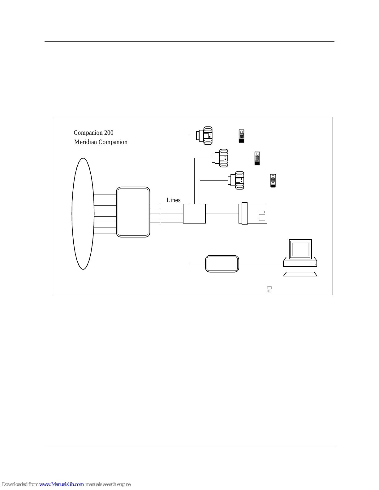
Local access connections
Figure 1 shows the connections that you must make to examine a
wireless system using CDS at the customer site. Refer to the
Remote
Access Device Installation Guide
if you require more detail on RAD
hardware connections or programming.
Figure 1: Overview of CDS local connections and wireless system
To connect the PC to the RAD
1. Connect one end of the RS232 cable to serial port 1 or 2 on the
PC using a connector that matches your PC’s port.
2. Place the PC within 100 feet (30 meters) of the RAD.
3. Connect the other end of the RS232 cable to the serial port on the
RAD using a female 25-pin connector or 9-pin connector as
required.
To connect the RAD to the Controller:
1. Connect one end of the RAD TCM cable to the RJ-11 port on the
back of the RAD using the RJ-11 connector.
Public
Switch
or
PBX
Controller
TCM
RAD
PC
Keyboard
Companion
Diagnostic
Software
CDS Application
Administrat ion
Terminal (M7310)
Distribut ion
Block
RS232 Cable
(max. 100 ft)
RAD
Base Stat ions
Public
Switch
or
PBX
Access
Lines
Portables
TCM
Cable
Companion 200
Lines
Meridian Companion

10 Companion Diagnostic Software basics
Companion Diagnostic Software for PCI User Guide P0886303 Issue 01 Standard
2. Place the RAD near the distribution block and within 100 feet
(30 meters) of the Controller.
Note:
Place the RAD as close as possible to the distribution block.
Make sure that the combined length of the RAD TCM cable
and the TCM lines between the distribution block and the
Controller is less than 100 feet (30 meters).
3. Connect the loose wires on the other end of the RAD TCM cable
to an allowable free port (one of the first five TCM ports) at the
distribution block.
Note:
Although any of the f irst f iv e TCM por ts are allow able for the
purposes of CDS, if you also intend to use the backup/restore
feature in Companion Manager, you should use the first TCM
port.
Ensure that the RAD TCM cable is free of bridge-taps and loading
coils.
Companion Diagnostic Software basics 11
P0886303 Issue 01 Standard Companion Diagnostic Software for PCI User Guide
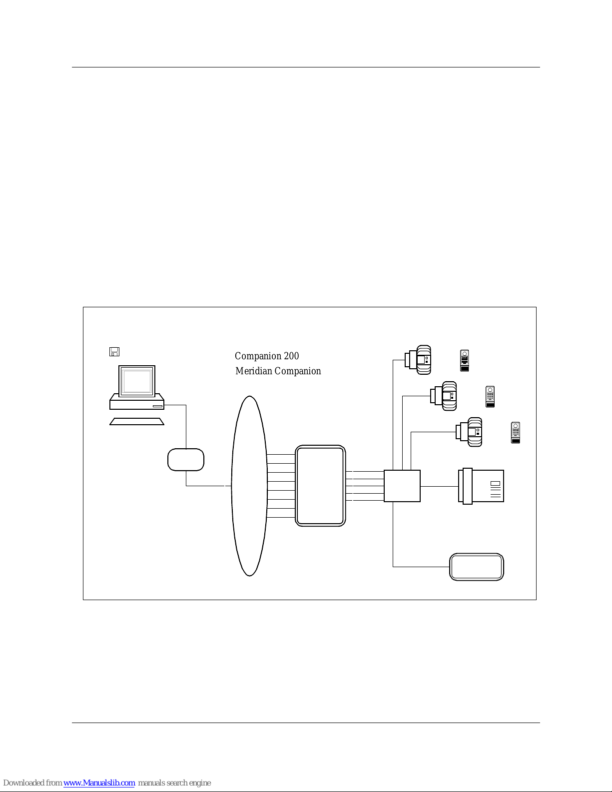
Remote access connections using the RAD internal modem
Figure 2 shows the connections that you must make to examine a
wireless system using CDS from a remote location via the RAD
internal modem. One of the lines into the Controller is dedicated to
the RAD. This line is not avail able for other devices. If a dedicated
line is not av ailable through the Controller , the RAD can share a line
with another device, although this is not recommended.
The RAD must be programmed to answer the line automatically
when the PC dials in through the public switch. Refer to the
Remote
Access Device Installation Guide
if you require more detail on RAD
hardware connections or programming. If you require more detail on
wireless system hardware connections, refer to the wireless system
documentation.
Figure 2: Overview of CDS remote connections using the RAD internal modem
Public
Switch
or
PBX
Controller
TCM
RAD
PC
Companion
Diagnostic
Software
CDS Application
Administration
Terminal
Distribution
Block
RS232
RAD
Base Stat ions
Public
Switch
or
PBX
Access
Lines
Portables
Lines
(M7310)
Cable
(max.
100 ft)
PC
modem
Public
Switch
Line
Keyboard
TCM
Cable
Companion 200
Meridian Companion

12 Companion Diagnostic Software basics
Companion Diagnostic Software for PCI User Guide P0886303 Issue 01 Standard
On-site connections required for remote access (with internal
modem)
To connect the RAD to the Controller:
1. Connect one end of the RAD TCM cable to the RJ-11 port on the
back of the RAD using the RJ-11 connector.
2. Place the RAD near the distribution block and within 100 feet
(30 meters) of the Controller.
Note:
Place the RAD as close as possible to the distribution block.
Make sure that the combined length of the RAD TCM cable
and the TCM lines between the distribution block and the
Controller is less than 100 feet (30 meters).
3. Connect the loose wires on the other end of the RAD TCM cable
to an allowable free port (one of the first five TCM ports) at the
distribution block.
Note:
While any of the first five TCM ports are allowable for the
purposes of CDS, if you also intend to use the backup/restore
feature in Companion Manager, you should use the first TCM
port.
Ensure that the RAD TCM cable is free of bridge-taps and
loading coils.
Off-site connections required for remote access (with internal
modem)
PC serial ports 1 and 2 are supported by CDS.
To connect the PC to an external PC modem:
1. Connect one end of the RS232 cable to serial port 1 or 2 on the
PC using a connector that matches your PC’s port.
2. Connect the other end of the RS232 cable to the serial port on the
PC modem using a connector that matches the modem serial
port.
Note:
The maximum length of an RS232 cable is 100 feet
(30 meters).
To connect the PC modem to the public switch:
1. Connect one end of the public switch line cable to the RJ -11 port
on the PC modem using an RJ-11 connector .
2. Connect the other end of the public switch line cable to the
public switch network.
Companion Diagnostic Software basics 13
P0886303 Issue 01 Standard Companion Diagnostic Software for PCI User Guide
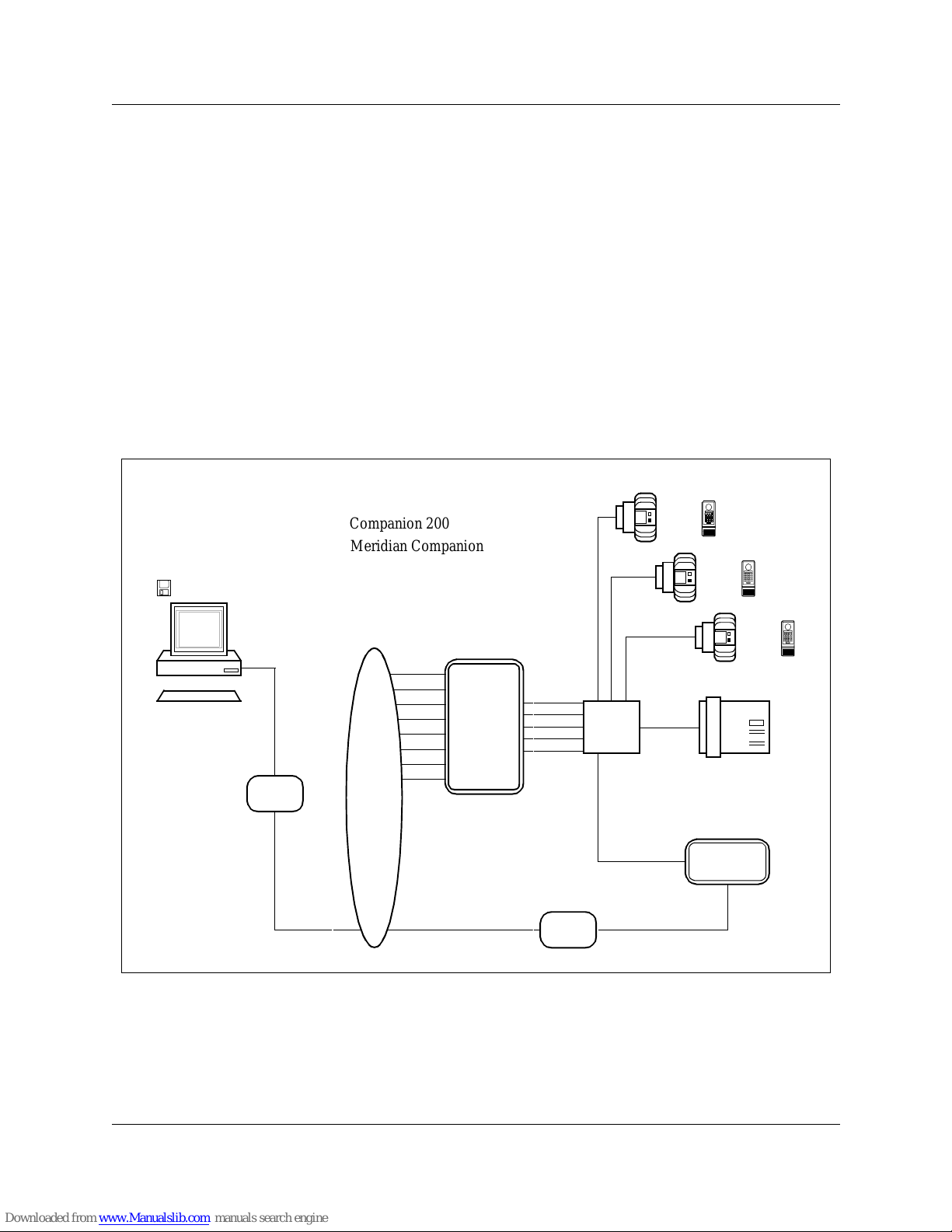
Remote access connections using a RAD external modem
T o e xamine a wireless system using CDS from a remote loc ation via
a RAD external modem, no line into the c ontroller is dedicated to the
RAD. A line connects the RAD external modem directly to the
public switch or Private Branch Exchange (PBX), bypassing the
Controller . The PC dials the telephone number assigned to this line.
The external modem is connected to the RAD by an RS232 null
modem cable. See Figure 3 for the connections you must make to
examine a wireless system using CDS from a remote location using
a RAD external modem.
Note:
Only 9600 baud can be supported with the external modem.
Figure 3: Overview of CDS remote connections using a RAD external modem
Public
Switch
or
PBX
Controller
TCM
RAD
PC
Companion
Diagnostic
Software
CDS Application
Administration
Terminal
Distribution
Block
RS232
RAD
Base Stat ions
Public
Switch
or
PBX
Access
Lines
Portables
lines
TCM
(M7310)
Cable
(max.
100 ft)
PC
modem
Public
Switch
Line
Keyboard
Public Switch
RAD
RS232 Null
Modem Cable
or PBX Line
External
Modem
Cable
Companion 200
Meridian Companion

14 Companion Diagnostic Software basics
Companion Diagnostic Software for PCI User Guide P0886303 Issue 01 Standard
On-site connections required for remote access (with external
modem)
To connect a RAD to the Controller:
1. Connect one end of a RAD TCM cable to the RJ-11 port on the
back of a RAD using the RJ-11 connector.
2. Place the RAD near the distribution block and within 100 feet
(30 meters) of the Controller.
Note:
Place the RAD as close as possible to the distribution block (a
32 inch (80 centimeter) cable has be e n provided). Ma ke sure
that the combined length of the RAD TCM cable and the
TCM lines between the distribution block and the Contr oller
is less than 100 feet (30 meters).
3. Connect the loose wires on the other end of the RAD TCM cable
to an allowable free port (one of the first five TCM ports) (refer
to the
Remote Access Device Installa tion Guide
) at the
distribution block.
Note:
Although any of the f irst f iv e TCM por ts are allow able for the
purposes of CDS, if you also intend to use the backup/restore
feature in Companion Manager, you should use the first TCM
port.
Ensure that the RAD TCM cable is free of bridge-taps and loading
coils.
To connect a RAD to a RAD external modem:
1. Connect one end of the RS232 null modem cable to the serial
port on the RAD using a female 25-pin connector.
2. Connect the other end of the RS232 null modem cable to the
serial port on the RAD external modem using an appropriate
connector.
To connect a RAD external modem to the public switch or PBX:
1. Connect one end of the line cable to the RJ-11 port on the RAD
external modem using an RJ-11 connector.
2. Connect the other end of the line cable to the public switch or
PBX.
Note:
Only 9600 baud can be supported with the external modem.

Companion Diagnostic Software basics 15
P0886303 Issue 01 Standard Companion Diagnostic Software for PCI User Guide
Off-site connections required for remote access (with external
modem)
PC serial ports 1 and 2 are supported by CDS.
To connect the PC to an external PC modem:
1. Connect one end of the RS232 cable to serial port 1 or 2 on the
PC using a connector that matches your PC’s port.
2. Connect the other end of the RS232 cable to the serial port on the
PC modem using an appropriate connector.
Note:
The maximum length of an RS232 cable is 100 feet
(30 meters).
To connect the PC modem to the public switch:
1. Connect one end of the public switch line cable to the RJ -11 port
on the PC modem using an RJ-11 connector .
2. Connect the other end of the public switch line cable to the
public switch network.
Wireless system programming
The following is a summary of the wireless system progra mming
required for a local or remote connection. This programming is
performed on the wireless system’s Administration Terminal, and
should be recorded in the Programming Record of the
Remote
Access Device Installation Guide
. Programming mus t be co mpleted
at the customer site before you can use CDS. Refer to the
Remote
Access Device Installation Guide
if you require more detail on RAD
programming. Refer to the wireless system documentation if you
require more detail on wireless system programming.
Note:
A RAD cannot be programmed if an RS232 cable is connected
to its serial port. Ensure that the required RAD programming
has been done before connecting the R S232 cable to the RAD
serial port.
Note:
The System ID must be programmed for the RAD before you
can proceed. Refer to the
Remote Access Device Installation
Guide
for instructions on how to program the System ID for
the RAD. The RAD password defaults to the System ID.

16 Companion Diagnostic Software basics
Companion Diagnostic Software for PCI User Guide P0886303 Issue 01 Standard
Note:
Displayed data is referenced to the time and date of the
system. To ensure accurate referencing, use the
Administration Terminal to set the time correctly.
Local access programming
Ensure that the following steps have been completed before setting
up a new CDS site with local access :
• System ID programmed for the RAD
Remote access programming using the RAD internal modem
Ensure that the following steps have been completed before setting
up a new CDS site with remote access using the RAD inter n al
modem:
• the line into the wireless system dedicated to the RAD (note the
telephone number)
• System ID programmed for the RAD
• line type programmed as Key Service Unit (KSU) for the RAD
• allowable line number programmed for the RAD (refer to
Remote
Access Device Installation Guide
)
• Auto Answer programmed for the RAD
The Auto Answer settings programmed depend on how the RAD
internal modem is used.
If a line is
dedicated
to the RAD:
• set auto answer ‘on’ for the RAD
• set the number of rings before auto answer to ‘1’
If a line is
shared
with the RAD:
• set auto answer ‘on’ for the RAD
• set the number of rings before auto answer to a number between
‘1’ and ‘10’
Note:
Beware of any telephony application that may cause the call
to be answered before the RAD answers automatically (e.g.,
Call Forward or Voice Mail).
In the case of a shared line, an alternate approach, is to set RAD Auto
Answer ‘off’ for normal wireless system operation. When you need

Companion Diagnostic Software basics 17
P0886303 Issue 01 Standard Companion Diagnostic Software for PCI User Guide
to initiate a diagnostic session, contact someone at that site and ask
them to program RAD Auto Answer ‘on’, with the number of rings
before Auto Answer to ‘1’. You may then make the modem call to
the site and perform the diagnostics. At the end of the session,
contact the on-site person and ask them to program RAD Auto
Answe r ‘o ff’ again.
Remote access programming using a RAD external modem
Ensure that the following have been completed before setting up a
new CDS site with remote access using a RAD external modem:
• public switch line connected direc tly to the RAD external modem
(note the telephone number)
• System ID programmed for the RAD
Note:
The only modem speed supported for this configuration is at
9600 bps.
Make a working copy
Make a working copy of the original CDS diskette. Use the working
copy diskette to install CDS on your hard dri ve or to use CDS from
your floppy drive. Store your original diskette as backup.
Installing and using CDS on your hard drive
To install CDS on your hard drive:
1. Insert the working copy diskette of CDS into your floppy drive.
Assuming your hard drive is ‘C’ and your floppy drive is ‘A’,
2. At the MS-DOS
C:\>
command prompt, type:
A:
and press
3. At the prompt A>, type:
CD_SETUP
<source-drive> <destination-drive>
for example: CD_SETUP A C
and press
Enter
Enter

18 Companion Diagnostic Software basics
Companion Diagnostic Software for PCI User Guide P0886303 Issue 01 Standard
Note:
The DOS commands in CD_S ETUP a nd similar applications
are not case-sensitive.
A
CDSPCI
directory will be created containing all the files listed
below (see ‘Files needed by CDS’ and also ‘Appendix E’). You can
now use CDS from your hard drive.
Using CDS from your floppy drive
You can use CDS from your floppy drive, b ut beware of diskette
space limitations. If you plan to use CDS from your floppy drive:
1. Insert the working copy diskette of CDS into your floppy drive.
You can now use CDS from your floppy drive. Ensure that DOS
write protect is off and that the diskette remains in the floppy drive
for the entire CDS session. To set up, follow the same procedure as
for setting up CDS for a new site. See the section on ‘Site
administration’.
Files needed by CDS
The CDS application provides a directory called CDSPCI at the
highest level on the drive that you have chosen. The following files
are in the CDSPCI directory and are required to use the application:
•
CDS.EXE
: the main CDS program
•
CDS_ADM.EXE
: the CDS Administration Utility program
•
HELVB.FON
: the Helvetica font used to format text on the
display screens of CDS
•
RUNCDS.EXE
: the batch program for CDS, only required when
CDS is run in batch mode
•
LNG_MSG.DAT
: the default language file

P0886303 Issue 01 Standard Companion Diagnostic Software for PCI User Guide 19
Site administration
• Location access
• Administration data

20 Site administration
Companion Diagnostic Software for PCI User Guide P0886303 Issue 01 Standard
To create new sites or change the administration data of an existing
site, you must first access the CDS Administration Utility. CDS can
be set up to investig ate and store data for multiple sites.
The steps to create a new site or change the administration data of an
existing site var y with the type of connection, either local or remote.
If you want to use CDS on an existing site with its current
administration data, go dire ctly to ‘Starting CDS’ in the Us ing CDS
section of this guide.
Setting up CDS for a new site
When you are setting up CDS for a new site, you must know the
RAD System ID of the wireless system and the set value that
determines the edge of a cell or “cell edge RSSI” (default is
-70 dBm).
Note:
The System ID must be programmed for the RAD before you
can proceed. Refer to the
Remote Access Device Installation
Guide
for instructions on how to program the System ID for
the RAD. The RAD password defaults to the System ID.
Local access
To set up a new site with local access:
1. Change to the CDSPCI directory. Type:
CD \CDSPCI
and press
2. Open the CDS Administration Utility. Type:
CDS_ADM
and press
3. When you are prompted for the site name, type an alphanumeric
name with a maximum of eight characters to identify the new
site, and press:
4. If no site sub-directory by that name exists, a prompt will ask
you to confirm the new site name. When you are prompted for
this confirmation, type:
Enter
Enter
Enter

Site administration 21
P0886303 Issue 01 Standard Companion Diagnostic Software for PCI User Guide
Y
press
and go directly to step 5.
OR
If a site sub-directory by that name exists, the previous RAD
password of the existing site is presented on your PC screen. A
prompt will ask you to enter a new RAD password. If you do not
want to change the value, you can press to get the
previous value.
If you still want to create a new site, return to step 2 and repeat the
procedure with another site name.
Note:
Once you have opened the administration data of an existing
site, you must follow all of the prompts before you are able to
exit. If you do not want to change a value, you can
press to get the previous value.
5. When you are prompted for the RAD password, a maximum of
10 numeric characters, type the RAD password and press:
Note:
The RAD password is the same as the System ID, unless
another application has changed it.
6. When you are prompted for the type of connection, type:
L
and press
7. When you are prompted for the PC serial port, type the one-digit
number (1 or 2) that identifies the serial port on the PC that is
connected to the serial port on the RAD. Press:
8. When you are prompted for the cell edge RSSI, type the cell
edge RSSI (default is -70 dBm). Press:
Enter
Enter
Enter
Enter
Enter
Enter
Enter

22 Site administration
Companion Diagnostic Software for PCI User Guide P0886303 Issue 01 Standard
When the new site sub-directory has been successfully created, CDS
displays a message and exits the CDS Administration Utility.
Remote access
When you are setting up CDS for a new site with remote access, you
must know some relev ant wireless system values. Before you begin,
obtain the follo wing values from the wireless system coordinator at
the site.
RAD System ID
The System ID/password programmed for the
RAD.
Telephone number
The telephone number of the line dedicated to
the RAD internal modem or the external modem. Valid characters
for remote access are the digits 0 to 9 and a comma (,). The comma
can be used to make the modem pause for dial tone. The duration of
the pause is modem dependent.
Dial type
The dial mode, Pulse or Tone, of the line connecting the
PC modem to the public switch.
Cell edge RSSI
The system measured RSSI value at the cell edge
(default is -70 dBm).
Note:
If the required wireless system programming has not been
done, you must complete these tasks before you can proceed.
See ‘Wireless system programming’ in the CDS Basics
section of this guide for more detail on wireless system
programming requirements.
Site administration 23
P0886303 Issue 01 Standard Companion Diagnostic Software for PCI User Guide
To set up a new site with remote access:
1. Follow steps 1 to 5 under the ‘Local access’ heading.
2. When you are prompted for the connection type, type:
R
and press
3. When you are prompted for the number to dial, type the
telephone number assigned to the line dedicated to the internal
or external RAD modem and press:
4. A prompt will ask for the dial type of t he line connecting the PC
modem to the public switch. When prompted for the dial type,
type:
P
for Pulse or T for Tone
and press
5. When you are prompted for the modem speed, type the baud rate
(300, 1200, 2400, 9600) for the PC modem and press:
Note:
A baud rate of 300, 1200, and 2400 for the PC modem dictates
the baud rate of the RAD internal modem. The 9600 baud rate
can only be used in the case of an external modem connected
to the RAD via a RS232 null modem cable, or in the case of
an autobaud with the FastRad.
6. You will be prompted with the recommended modem
initialization string. You will then be prompted with the current
modem initialization string. When you are creating a new site,
the current modem initialization string is the same as the
recommended one. If you do not want to change the modem
initialization string press:
and go directly to step 7.
OR
Enter
Enter
Enter
Enter
Enter

24 Site administration
Companion Diagnostic Software for PCI User Guide P0886303 Issue 01 Standard
If the PC modem is Hayes compatible but does not default to the
Hayes mode, you will need to change the modem initialization
string. Type the string required by the Hayes compatible PC
modem and press:
Note:
See Appendix A in this guide for further information on the
PC modem initialization string.
7. When you are prompted for the PC serial port, type the one-digit
number (1 or 2) that identif ies the serial port on the PC connected
to the serial port on the PC modem. Press:
8. When you are prompted for the cell edge RSSI, type the cell
edge RSSI (default is -70 dBm) . Press:
When the new site sub-directory has been successfully created, CDS
displays a message and exits the CDS Administration Utility.
Files created by setting up a new site
The procedure to set up CDS for a new site creates a site subdirectory with an extension of
.SIT
in the main CDSPCI
directory. You can have many site sub-directories in the main
CDSPCI directory. The following file is in each site sub-directory:
CDS_ADM.DAT
This site administration file contai ns the administration da ta
pertaining to the site for which the sub-directory was created.
Changing the administration data of an existing site
If relevant wireless system programming, or the type of connection
has changed, any attempt to start CDS for an e xis ting s ite under the
previous administration data will result in an error. Before you can
successfully start CDS for that site, you must access the CDS
Administration Utility and change the administration data of the
affected CDS site to correspond to the new wireless system values.
Enter
Enter
Enter

Site administration 25
P0886303 Issue 01 Standard Companion Diagnostic Software for PCI User Guide
Note:
Once you have opened the CDS Administration Utility for an
existing site, you must follow all of the prompts before you
are able to exit. If you do not want to change a value, you can
press the key to get the previous value settings.
Local access
To change the administration data of an existing site with local
access, or to change an existing site from remote acces s to local
access:
1. Change to the CDSPCI directory. Type:
CD \CDSPCI
and press
2. Open the CDS Administration Utility. Type:
CDS_ADM
and press
3. When you are prompted for the site name, type the alphanumeric
name that identifies the existing site. Press:
4. If a site sub-directory by that name exists, the previous RAD
password of the existing site is presented on your PC screen. A
prompt will ask you to enter the new RAD password with a
maximum of 10 numeric characters. When you are prompted,
type the new RAD password. Press:
Go directly to step 5.
If you do not want to change the RAD password of the existing
site, press:
OR
If no site sub-directory by that name exists, a prompt will ask
you to confirm a new site name. If you still want to attempt to
change the administration data of an existing site, you must
return to step 3 and try again.
Enter
Enter
Enter
Enter
Enter
Enter
 Loading...