

Nortel Meridian Companion Reference Manual
NOTICE: Notwithstanding any explicit confidentiality or proprietary markings to the contrary, the
information contained in this document has been reviewed and approved for public disclosure
by Nortel. However, the access to, use and disclosure of this document and the information
contained therein continue to be subject to copyright and other restrictions, conditions and
limitations as detailed in the Terms of Use. (http://www.nortel.com/help/legal/index.html)
Meridia n 1
Meridian Companion
Site Planning Refere nce Manual
Document Number: 553-3601-106
Document Releas e: Stan dard 2.00
Date: September 1996
Copyright @ 1996—1999 Nortel Networks, All Rights Reserved
Printed in Canada
The information contained herei n is the p roperty of Nortel Netw orks and is strictly confidential. Ex cept as
expressly authorized in writing by Nortel Networks, the holder shall keep all information contained herein
confidential, shall disclose the information only to its employees wit h a need to know, and shall protec t the
information, in whole or in part, from disclosure and dissemination to third parties with the same degree of
care it uses to protect its own confidential information, but with n o less than reasonable care. Except as
expressly authorized in writing by Nortel Networks, the holder is granted no rights to use the information
contained herein.
Meridian 1, S L-1, and Compan ion are trademar ks of Nortel Networks Corporation.
NORTEL NETWORKS CONFIDENTIAL
Meridian Companion Site Planning Reference Manual


Contents
About this manual ....................................................1
Companio n syste m overview ...................... ..... ..... ..3
Introduction to the Companion system......................................3
Base Stations............................................................................5
Radios and antennas .............................................................................5
Base Station location ...............................................9
Base Station installation guidelines...........................................9
Installing multiple Base Stations in a cell center ..................................11
Page iii of vi
Companio n Deploymen t Tool... ..... .... ..... ...............13
Using the CDT............................... ......... .......... ......... ......... .....13
CDT components ................................................................................. 14
How the CDT works.............................................................................14
Interpreting the portable’s tones...........................................................16
Conducting a CDT operational check .....................................17
Cell boundary values...............................................................18
Using the CDT to determine cell boundaries..........................19
Meridian Companion Site Planning Reference Manual

Page iv of vi
Site planning basics...............................................21
The basics of planning a site..................................................21
Site planning prerequisites.....................................................22
Required site information.................... ....................................22
Labeling a floor plan...............................................................24
Cell center location................................................................. 26
Covering outdoor areas........................................................................26
Covering a single floor indoor area....................................................... 29
Single-floor coverage techniques .........................................................31
Determining the number of Base Stations per cell.................37
Special cases .......................................................................................38
Reviewing your work...............................................................41
Checking system capacity....................................................................41
Reviewing with the customer................................................................41
Providing floor plan information............................................................42
Providing provisioning record information.............................................42
Planning a Sample Site..........................................43
Using what you learned..........................................................43
Sample Site: Site information.................................................43
Sample Site: Indoor cell center location.................................45
Sample Site: Determining the number of Base Stations per cell
48
Sample Site: Reviewing your work......................................... 53
Example outdoor cell center location...................................... 54
553-3601-106 Standard 2.00 September 1996

Page v of vi
Planning complex sites ......................................... 57
Planning a multi-floor coverage area...................................... 57
Atriums................................................................................................. 57
High-rise buildings ............................................................................... 58
Differing floor areas.............................................................................. 61
Planning an area of high portable density.............................. 63
Example of a high por table density area .............................................. 64
Planning where there is an existing Companion system........ 66
Adjacen t systems......................................... ..................... ................... 66
Overlapping systems ................ ..... ..... .... ..... .. ..... ..... .. ..... .. ..... .. ..... ..... ..66
Planning multiple systems...................................................... 67
Parameters affecting multiple systems ................................................. 67
System names.......... ..................... ............................ ...................... .... 68
Guidelines............................ ...................... ............................ .............. 68
Planning for multiple systems .............................................................. 69
Examples of four type s of multiple syste ms........ ....... ...................... .... 70
Appendix A: Derivation of traffic procedure........85
Derivation of traffic procedure ................................................ 85
Basic traffic procedure ......................................................................... 85
Detailed traffic procedure..................................................................... 86
Appendix B: Using indoor external antennas ..... 89
Selecting the appropriate indoor antenna.............................. 89
Simulating indoor external antennas with the CDT................ 91
Using coaxial cable and an external antenna . . .................................... 91
Changing the cell boundary value . ....................................................... 91
Appendix C: Fading ............................................... 93
Fading..................................................................................... 93
Meridian Companion Site Planning Reference Manual

Page vi of vi
Appendix D: Key planning concepts....................95
Key planning concepts............................................................95
Synchronization......................................................................95
Power control.......................................................................... 96
Portables...............................................................................................96
Base Stat ion s ......................................... ............................ ..................96
Optimizing power control......................................................................97
Base Station and cell relationships.........................................97
Auto administration...............................................................................97
Portable originated calls.........................................................98
Optimizing portable originated calls......................................................99
System originated call............................................................99
System..................................................................................................99
Portable ................................................................................................ 99
Optimizing system originated calls.....................................................100
Hand-off................................................................................100
Optimizing hand-off ............................................................................1 01
553-3601-106 Standard 2.00 September 1996

About this manual
This manual is used by the Companion s ite planner to plan and ins tall the best
possible Companion system for the site.
For the ba sic s of C ompani on si te pla nni ng, ref er to your Gui de to Site Planning .
Page 1 of 102
Meridian Companion Site Planning Reference Manual

1
Page 2 of 102 About this manual
553-3601-106 Standard 2.00 September 1996
Companion system overview
Introduction to the Companion system
The Companion system allows you to mak e and receive ca lls throughout your
site using a wireless telephon e.
As shown in Figure 1, the basic Companion system consists of a Controller,
Base S ta ti o n s an d a p ort ab l e for ea ch user. The Controller provid es the
connecti on between the external telephone s ystem, using acces s lines, and the
Companion system, using ports. Base Stations relay call informa tion between
the Controller and portables. Portables are wireless telephones.
Figure 1 : The basic Companio n System
cell center
portable
Base Station
cell
cell
Page 3 of 102
cell
link
access lines
Controller
ports
Meridian Companion Site Planning Reference Manual
1
Page 4 of 102 Companion system overview
As shown in Figure 2, the coverage a rea is the part of the site where the
customer wants to use their Companion system. The coverage area can be
indoors and outdoors.
Figure 2 : Cover age terminology
range
coverage
not
required
cell boundary
coverage
not
cell center
critical point
coverage area
required
When planning a site for coverage by a Companion system, the outermost
points from the center of the cov erage area are crit ical p oi nts. These points
may be difficult to pro vide radio cover age for so are covered first when
planning a site.
Covera ge is provided by grouping Base Station s into cell centers throughout
the cov erage area. A cell center provides tele phone coverage to a cell. Th e
point where coverage is no longer provided by the cell center is the cell
boundary. The distance from the cell c enter to the cell boundary is the rang e.
The radio communi cation bet ween a portab le and Base Sta tion is a li nk. When
a user walks from one cell into a nother , the link is tra nsferred to a B ase Station
in that cell by a hand-off between the two Base St ations. Any portabl e
register ed to the system can roam, because it can make or receive calls in any
cell.
553-3601-106 Standard 2.00 September 1996
1
Companion system overvie w P age 5 of 102
Base Stations
The Base S tation, as sho wn i n Figure 3, transmits c all inf ormation between the
Controller and the portable. T he Base Station is connected to the Controller
using standa rd tele phone wiri ng. The Base Stati on uses a wire les s connect ion
(radio) to communicate with the portable.
Figure 3 : Base Station
COMPANION
external entenna port
for radio 1
Radios and antennas
The Base Station has two radios, each with two internal antennas and one
ext erna l an ten na port . Us ing the tw o inte rna l ant enn as one at a time, the radio
selects the i nternal antenna that has the best signal strength. This process is
antenna diversity.
The ex ternal antenna po r ts for each Base Station radio can be connecte d to
external antennas by coaxial cables. In this case, the installer configures the
radios to use only the external antenna ports and there is no antenna diversity.
external antenna port
for radio 2
Meridian Companion Site Planning Reference Manual
1
Page 6 of 102 Companion system overview
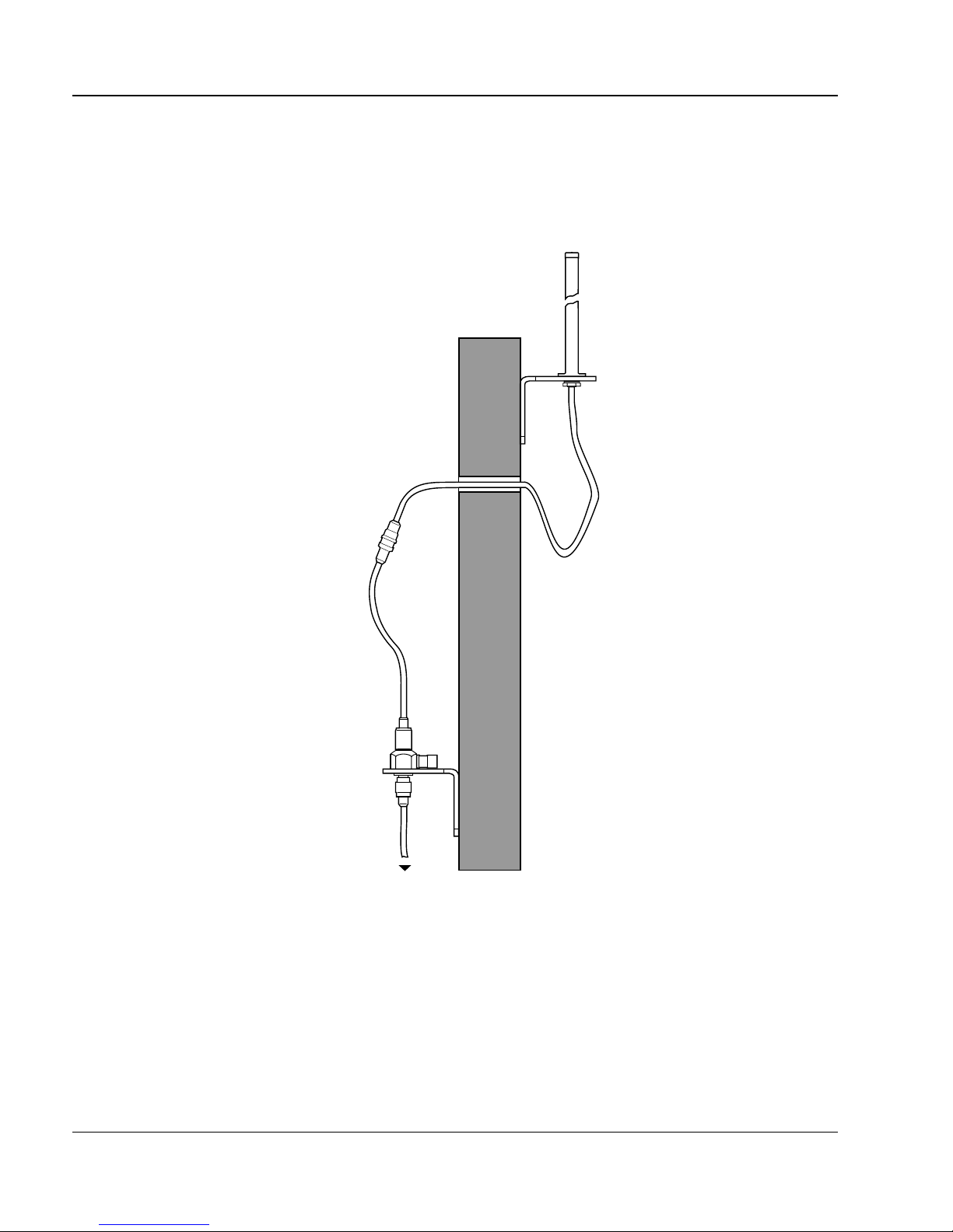
The antenna and lightning surge arrestor assembly for PCI is shown in
Figure 4.
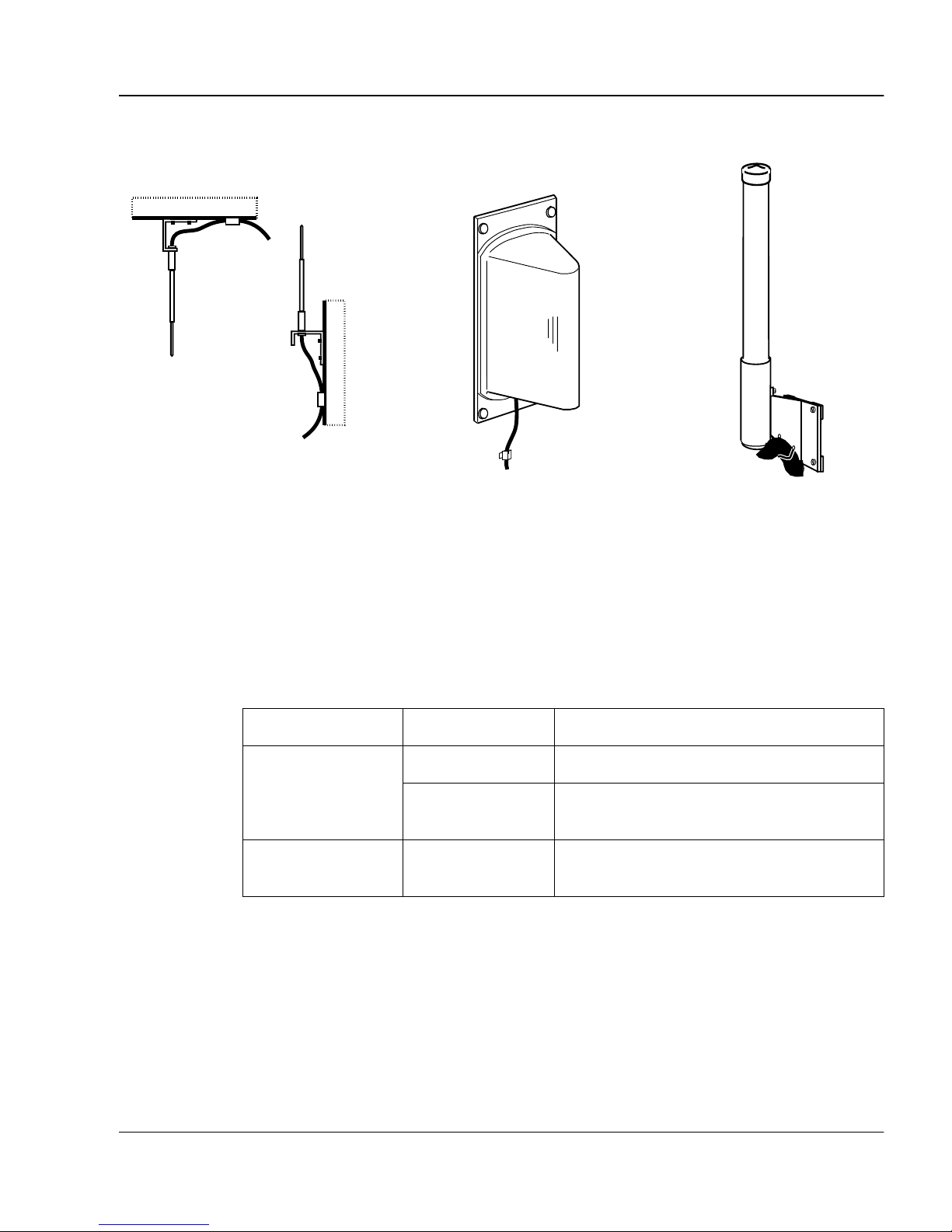
Several types of antennas for CT2Plus are sho wn in Fi gure 5.
Figure 4 : Antenna and lightning surge arrestor for PCI
proprietary
BNC connectors
lightning surge arrestor
with mounting bracket
wall
antenna
mounting bracket
to Base Station or proprietary extension cable
Note: The antenna has a gain between –1.2 and 1.5 dBi.
553-3601-106 Standard 2.00 September 1996
1
Companion system overvie w P age 7 of 102
Figure 5 : Examples of e xternal antennas f or CT2Plus
indoor omnidirectional
external antenna
Note: Not all types of external ante nnas are ava ilable in all count ries.
Inst al l ext er n al ante n n as at a cel l center as cl o se to g ether as p os s ib l e, with a
minimum dis tance of 40 in. (1 m). Table 1 shows t he pa ttern and gain of t hese
anten nas .
Table 1 : External antenna types
Type of antenna Pattern Gain
indoor omnidirec ti onal 0 dB in all directions.
outdoor omnidirec ti onal 2 dB in the horizontal plane. Gain is
indoor directional
external antenna
outdoor omnidirectional
external antenna
directional 3 dB in direction of beam , 0 dB at right
angles to direction of beam.
negative abo ve or bel ow the antenna.
Meridian Companion Site Planning Reference Manual

1
Page 8 of 102 Companion system overview
553-3601-106 Standard 2.00 September 1996

Base Station location
Base Station installation guidelines
• Ensure that the installation complies with your local electrical code.
• Do not plan to install Base Stations in ducts, plenums or hollow spaces
that transp o rt air, except where a suspended ceilin g creates th e duct,
plenum or hollow space with lay-in panels or tiles.
• Install Base Stations indoors where there is no condensation and the
temperatur e r emains between 32° and 12 0 °F (0° and 50°C). The ideal
temperatur e is betwee n 6 0° an d 95°F (15° and 35°C).
• Install all Base Stations within 4,000 ft (1 200 m) (wiring length for 24
AWG) of the Controller.
• Do not position Base Stations on large concrete or marble col umn s. Base
Stations must be at least 40 in. (1 m) from columns and located at a cell
center on th e s am e s ide of the columns.
Page 9 of 102
• Position Base Stations on ceilings or upright against walls at a height
where the re is t he le ast number of ob struc tio ns be tween t he Ba se Sta ti ons
and th e ce ll edg e (usually close to th e ceiling) .
Installing Base Stations on the ceiling has the following advantages over
installing Base Stations on a wall:
Meridian Companion Site Planning Reference Manual

1
Page 10 of 102 Base Station location
— it is easy for you to keep the Base Stations beyond the minimum
distance from where users frequently use their portable, such as in
offices
— it gives you more planning flexibility
Install Bas e Stations on the ceiling unless
— the ceiling has architectural or decorative feature s that prohibit the
installation of Base Stations
— the ceiling construction pre vents you fr om mounting a Base Sta tion
on it
— the ceiling is made of a material t hat does not all ow you to run wirin g
to Base Stations mounted on it
— the customer requests that Base Stations not be mounted on the
ceiling
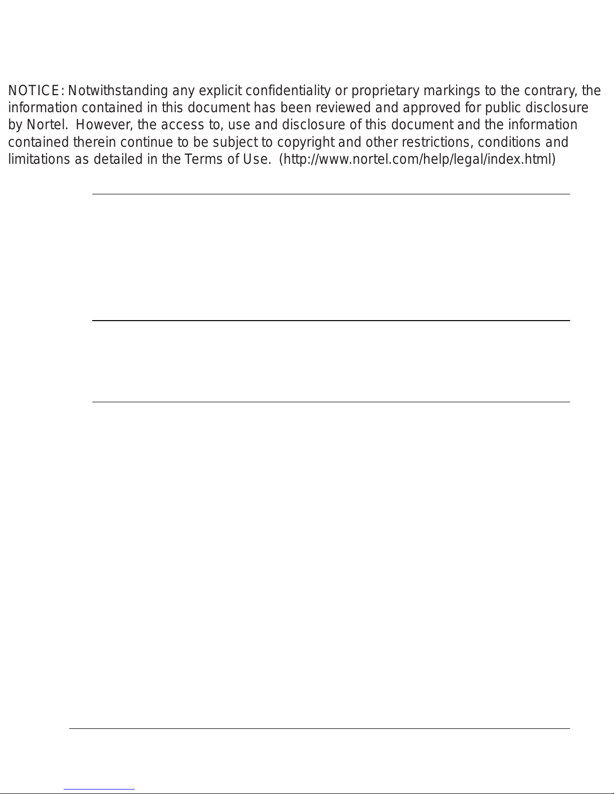
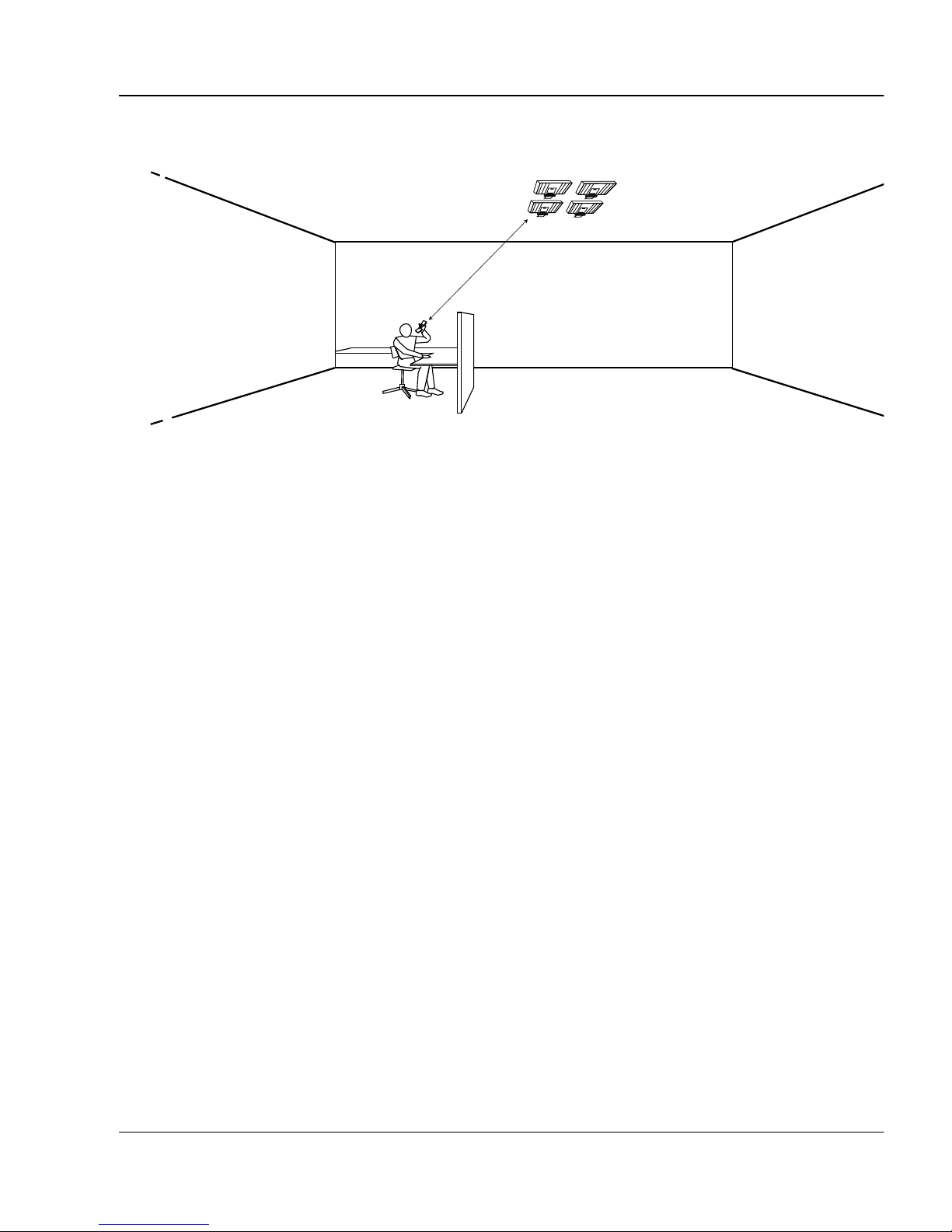
• Position Base Stations aw ay from where a portable is used in an office
by at least the amount shown in Table 2, and as illustrated in Figure 6.
Installing the Base Stations on ceilings or high on walls helps to
mainta in these mini mum distances.
Table 2 : Minimum distance between off ice areas and Base Stations
Number of Base Stations
in the cell
140in.(1.0m)
256in.(1.4m)
372in.(1.8m)
480in.(2.0m)
Minimum distance between
office areas and Base Stations
553-3601-106 Standard 2.00 September 1996
1
Base Station location Page 11 of 102
Figure 6 : Minimum distance of portables to Base Sta tions
N
IO
N
A
P
M
O
user's office
C
N
o
rth
e
rn
T
e
le
co
m
N
IO
N
A
P
M
O
C
N
o
rth
ern
T
e
le
co
m
80 in. (2.0 m) minimum
N
IO
N
A
P
M
O
C
N
orth
ern
Te
lec
om
N
IO
N
A
P
M
O
C
N
o
rthe
rn
T
e
lec
om
Installing multiple Base Stations in a cell center
In cas es wh ere t here i s mo re tha n one Base St atio n at a cell cen ter , f ollo w t hese
guidelines :
• Position all of the Base Stat ions on the same surface with ma tching
composition.
1
• Allow a clearance of at least 3
and surrounding objects.
• Do not position more than four Base Stations in a single cel l.
For CT2Plus protocol
• Position all the Base St ations that are at th e same cell center n o more
than 5 ft (1.5 m ) and no less than 3
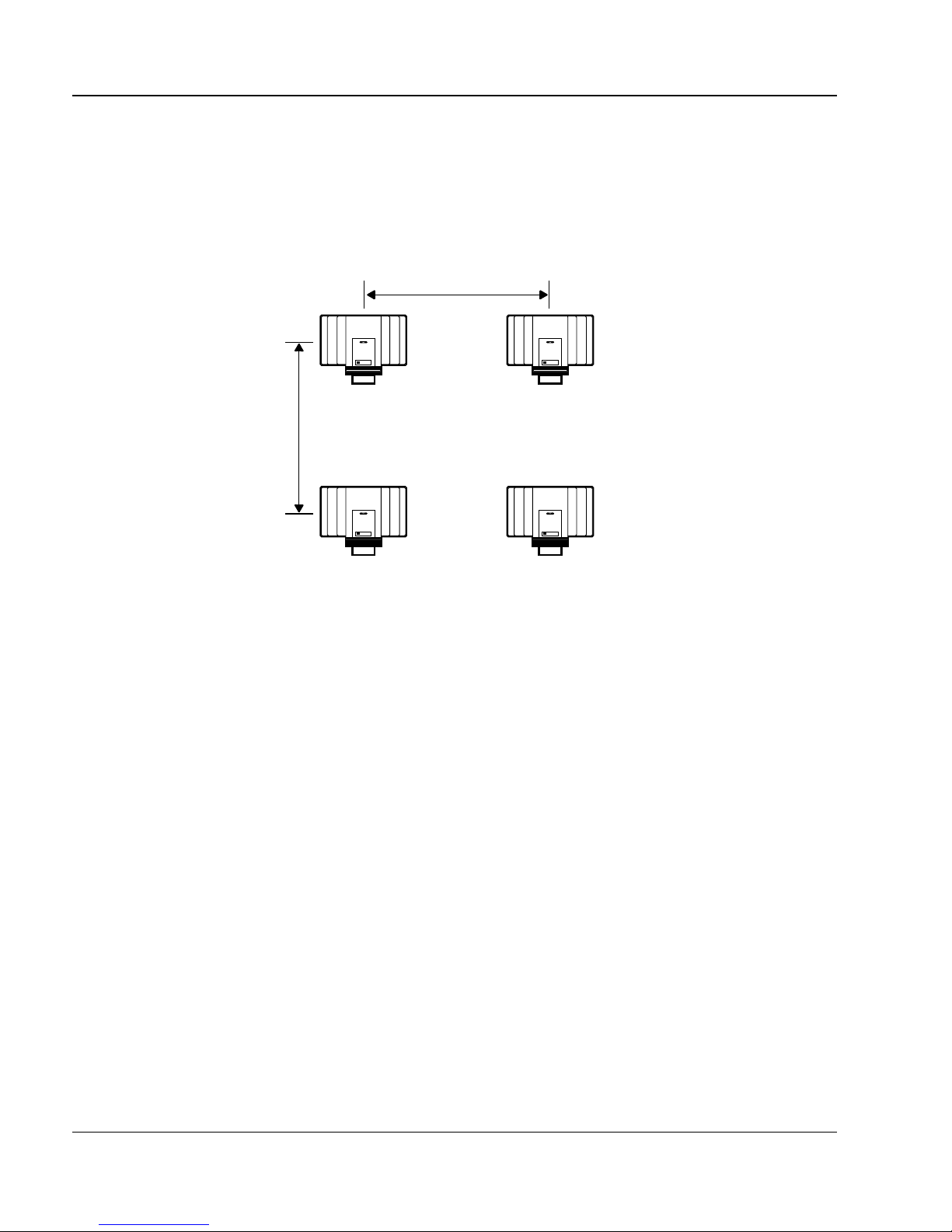
• Position the Base Stations on a ceiling as shown in Figure 7.
For PCI protocol
• Position the Ba se Stations as close together as possib l e but mai ntain a
minimum distance of 54 in. (1.35 m) apart (center to cente r) at t he same
cell center .
/2in. (9 cm) between the Base Stations
1
/2in. (9 cm) from each other.
• Do not mount Base Stations in rows.
Meridian Companion Site Planning Reference Manual
1
Page 12 of 102 Base Station location
• If there are three or four Base Stations at the cell center, install them on
the ce iling.
• If there are one or two Base Stations at the cell centers, you can install
the Base Sta tions upright on a wall, or on a cei ling as sho wn in Figure 7.
Figure 7 : Base Station posi tioning
COMPANIONCOMPANION
COMPANIONCOMPANION
553-3601-106 Standard 2.00 September 1996
Companion Deployment Tool
Using the CDT
This sectio n desc ribes how yo u us e the Comp anion Dep lo yment Tool (CDT) to
determine cell centers and cell bound aries.
For more information on using the CDT, refer to Companion Deployment Tool
User Guide.
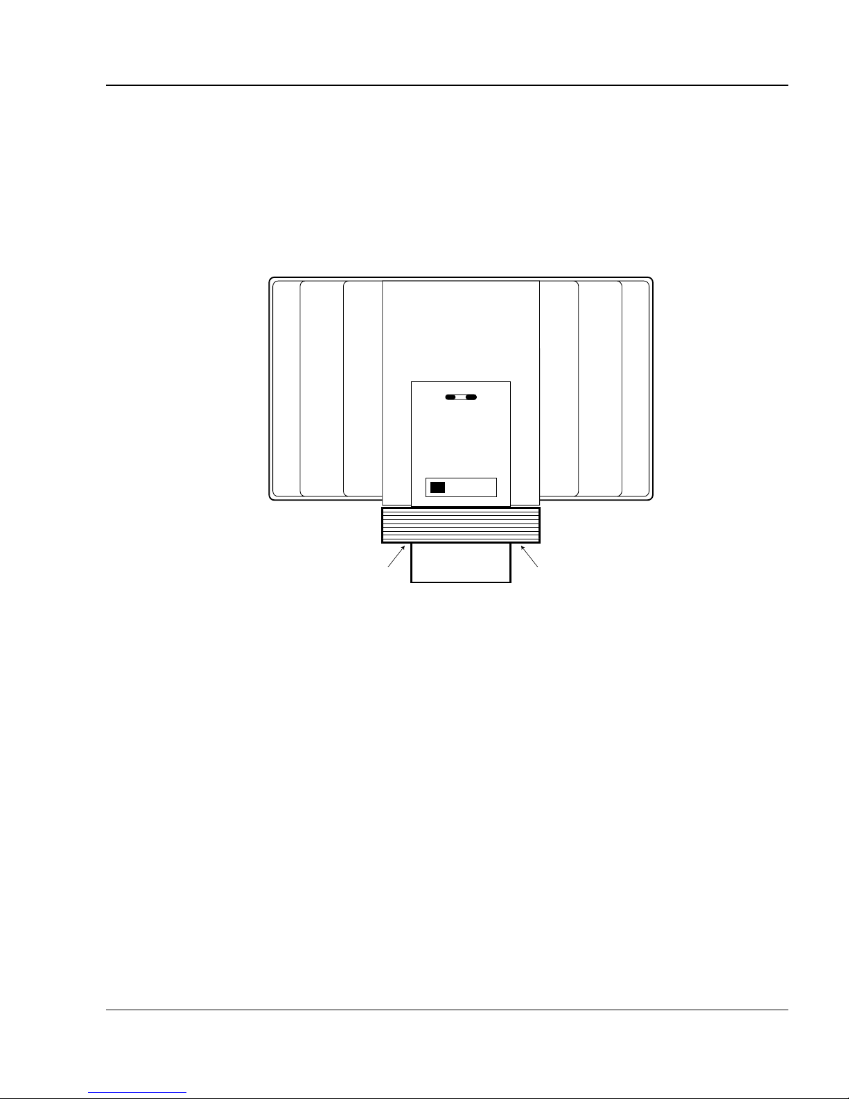
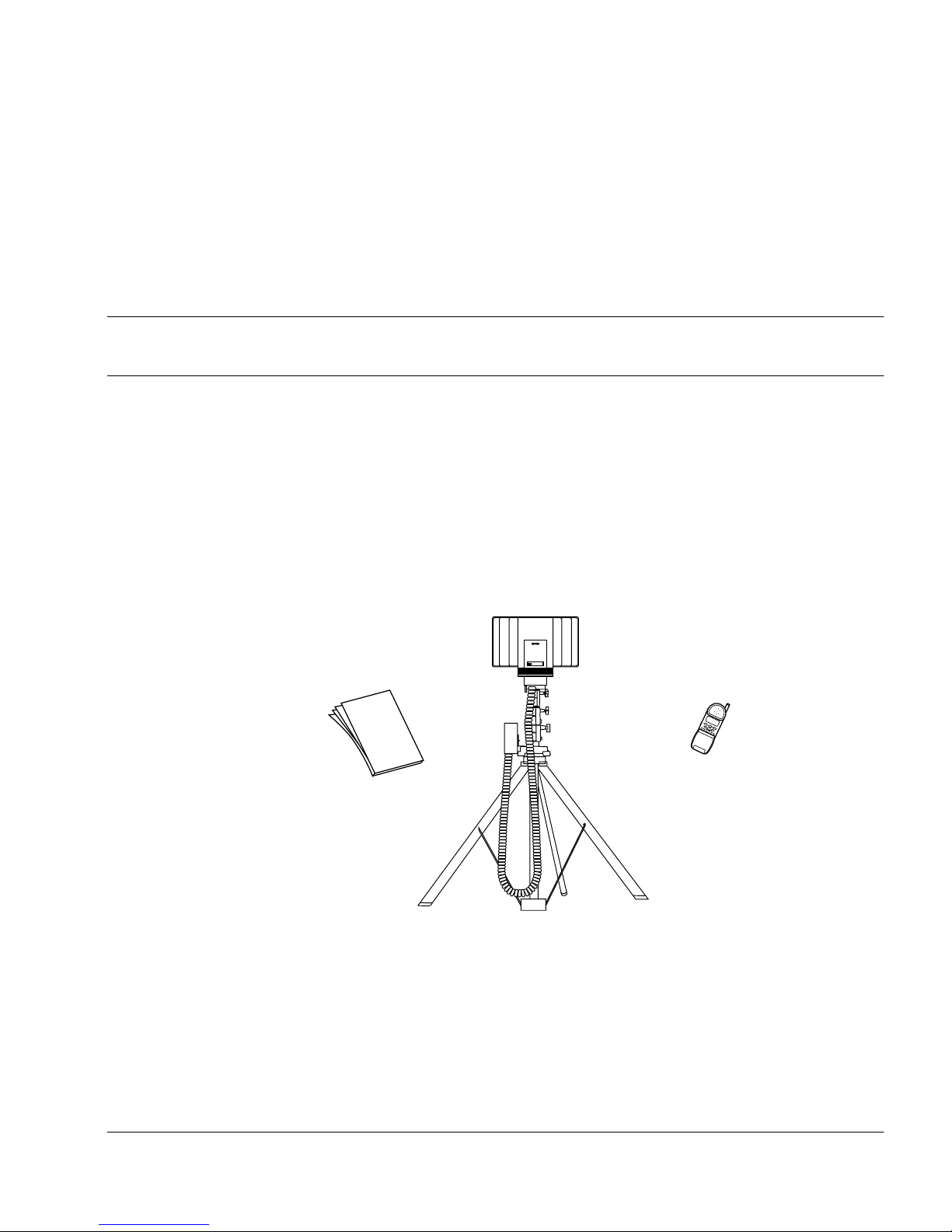
Figure 8 : Companion Deploym ent Tool
COMPANION
Page 13 of 102
documentation
battery
Northern
Telecom
CDT transceiver
portable
stand
Meridian Companion Site Planning Reference Manual

1
Page 14 of 102 Companion Deployment Tool
CDT components
The CDT consists of the following components:
•a stand
• a CD T tran s c eiver
Note: The CDT transceiver will not function as a Base Station. You
cannot connect it to the Controller.
• a ba t tery in s i de a ba tt er y hol d e r
•a portable
• CDT documentation
When used wit h the CDT transceiver, the portable continuously dis plays two
value s. The signal stre ngth is on the left and the cyclic redundanc y check error
rate is on the right . The signal strength is th e signal tr ansmitte d by the portabl e
and received by the CDT transceiver. For an explanation of the cyclic
redundancy che ck, refer to Companion Deployment Tool User Guide.
How the CDT works
Refer to Companion Deployment Tool User Guide for instructions on
assembling the tool, establ ishing a link, setting the cell bound ary value, and
choos i n g the external antenna with the CDT transceiver.
The CDT uses the internal antennas as a default, but th is default can be
changed to the e xternal anten na. The cell boun dary val ue is the signal st rength
used with the CDT to determine the cell boundary and ca n also be changed.
When you have established a link wit h the portable, ente r the numbers as
shown in T a ble 3 into the dial pad to set which anten nas and what cell bound ary
value you want to use.
553-3601-106 Standard 2.00 September 1996

1
Companion Deployment Tool Pag e 15 of 102
Table 3 : Selecting the CDT antenna and setting the cell boundary value
Entered number Operation
*894 shows the present selection and setting for 1 second
*895 selects the int ernal antennas and set s the cell boundary
value
*896 selects the external antenna and sets the cell boundary
value
*897 sets the cell boundary value
Note: When the CDT transceiver is powered off, the cell boundary value
rese ts to th e defau l t valu e a nd th e int er n al ante n n as ar e se le cted.
You will hear tones fro m the portabl e that indicate the rec eiv ed signal s trength.
Use the tones to determine the cell boundary. The received signal strength
value also appears on the portable’s display but the tones should be used to
determine cell centers and cell boun daries.
Note: The sig n al strength on the portable’s display use s dBm units.
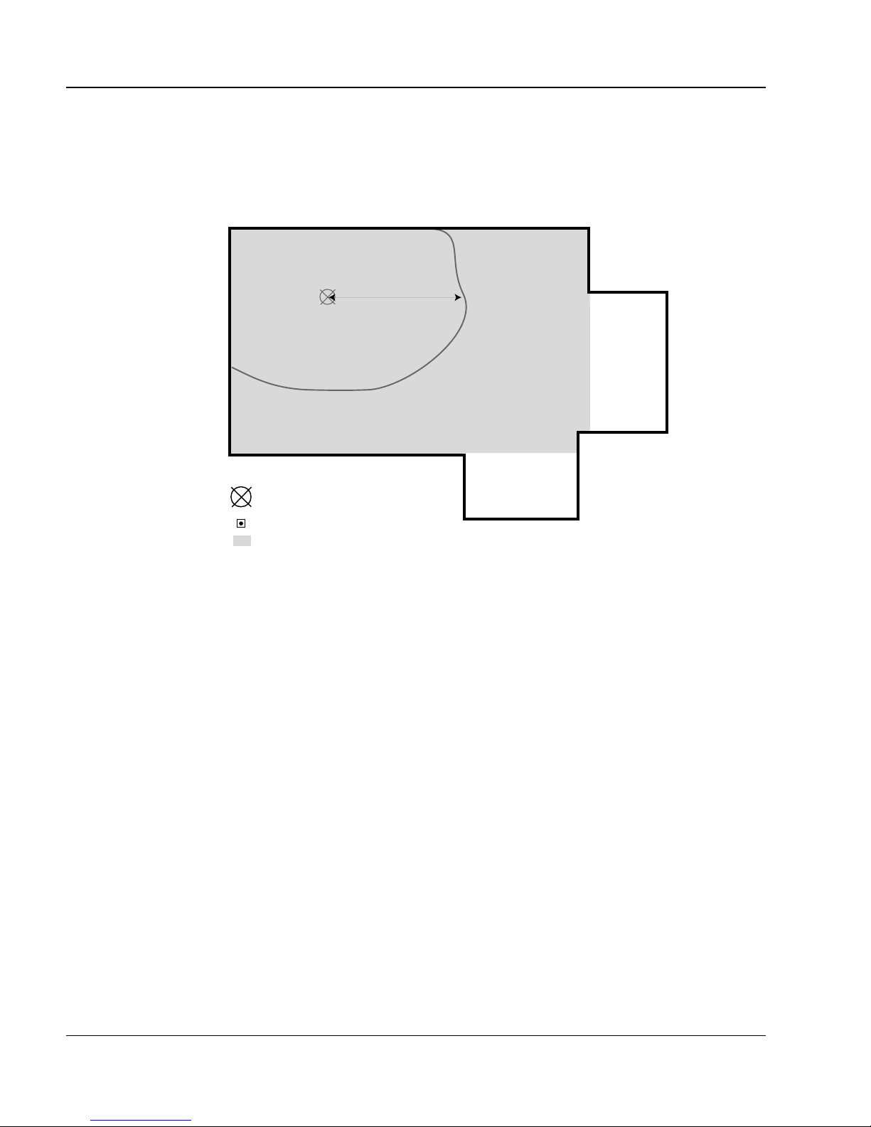
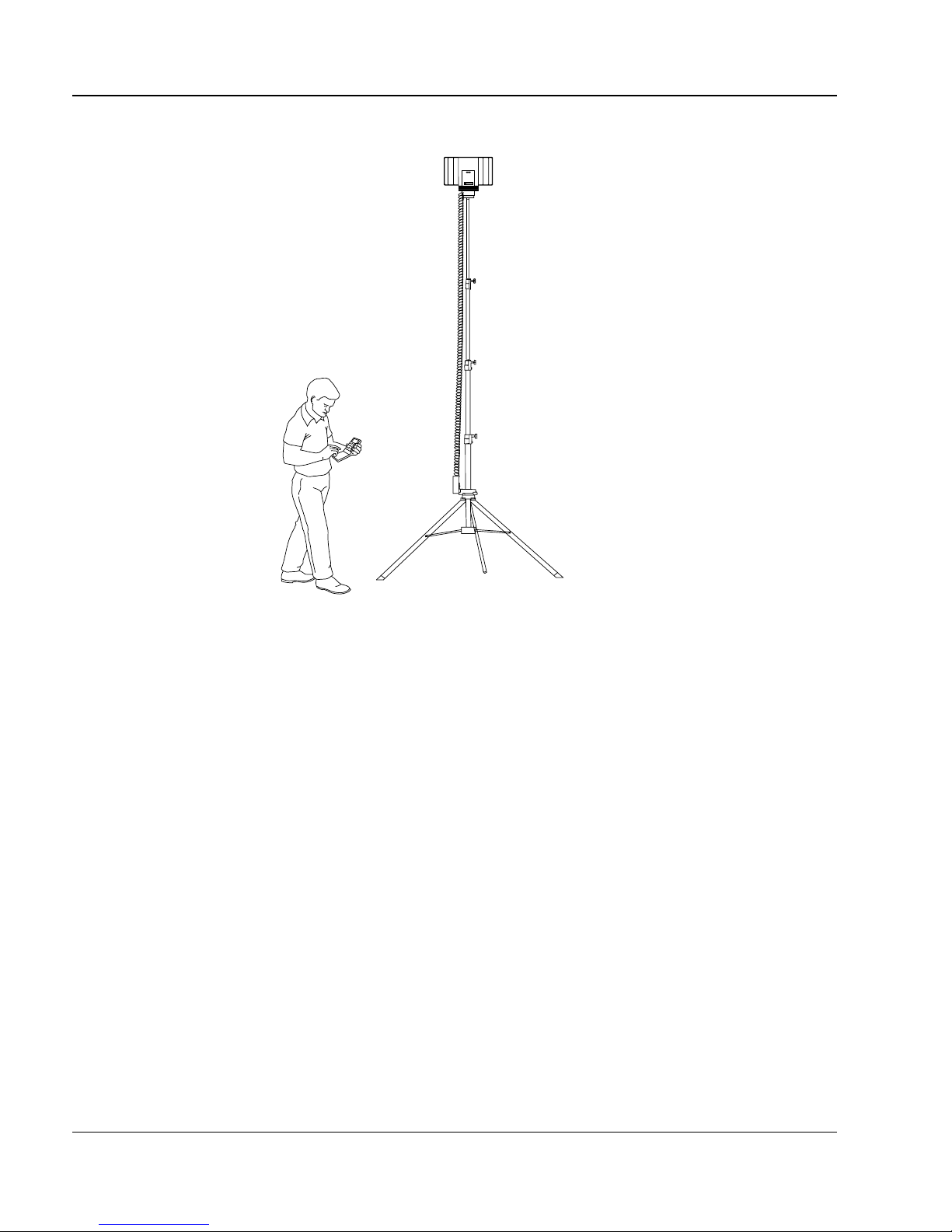
When you set the CDT transc ei ver a t a criti cal p oint, r aise the CDT tra nscei ver
as high as it can go or until it is at the height that you recommend for Base
Stations.
Meridian Companion Site Planning Reference Manual
1
Page 16 of 102 Companion Deployment Tool
Figure 9 : Fully raised CDT
COMPANION
Northern
Telecom
Note: The CDT stand is available in three heights: 8 ft (2.4 m), 12 ft (3.6 m)
and 16 ft (4.8 m).
Do not position your CDT transceiver next to large concrete or marble
columns. These structures affect the contour of the cel l boundary. Keep the
CDT transc eiver at least 40 in. (1 m) from columns.
Interpreting the portable’s tones
The portable make s the following tones to indicate how close you are to the
CDT transceiver:
• Steady tone—The signal strength is stronger than the cell boundary
value.
• Double beep, followed by a rhythmic high-low tone—The signal
strength is weaker th an the cell bounda ry v alue . The rhyt hmic high-low
tone persists as long as you remain where the signal strength is weak.
553-3601-106 Standard 2.00 September 1996

1
Companion Deployment Tool Pag e 17 of 102
• T riple beep, followed by a steady tone— The signal strength has
increase d to 6 dB stronger t han t he ce ll bounda ry value. The CDT r es ets
for you to make another measurement.
• No sound—If you lose the link, no tones are generated. If you move
closer to the CDT transceiver within 10 seconds, the link reest ablishes
itself.
Conducting a CDT operational check
Charge the battery for the CDT transceiver the day or night before and have a
fresh set of batteries for the portable. For details on how to charge the battery,
refer to Companion Deployment Tool User Guide.
Note: Do not set up the CDT tra nsceiver outdoors. The CDT is not intended
for outdoor use.
CDT using C T2 P l us prot ocol
1. Establish a link.
2. In an open ar e a, stand 33 ft (10 m ) fr om th e CD T transceiver wit h the
portable . Keep the CDT transce iver in pla in view and have no
obstructions nearby (including people).
If the di splay sho ws -44 , the CDT works proper ly . If t he display d oes not
show -44, repeat this procedure with a different portable. If the display
still does not show -44, replace the transcei ver.
CDT using PCI protocol
1. Establish a link.
2. In an open area, stand 10 ft (3 m) from the CDT transceiver with the
portable . Keep the CDT transce iver in pla in view and have no
obstructions nearby (including people).
If the di splay sho ws -35 , the CDT works proper ly . If t he display d oes not
show -35, repeat this procedure with a different portable. If the display
still does not show -35, replace the transcei ver.
Meridian Companion Site Planning Reference Manual
1
Page 18 of 102 Companion Deployment Tool
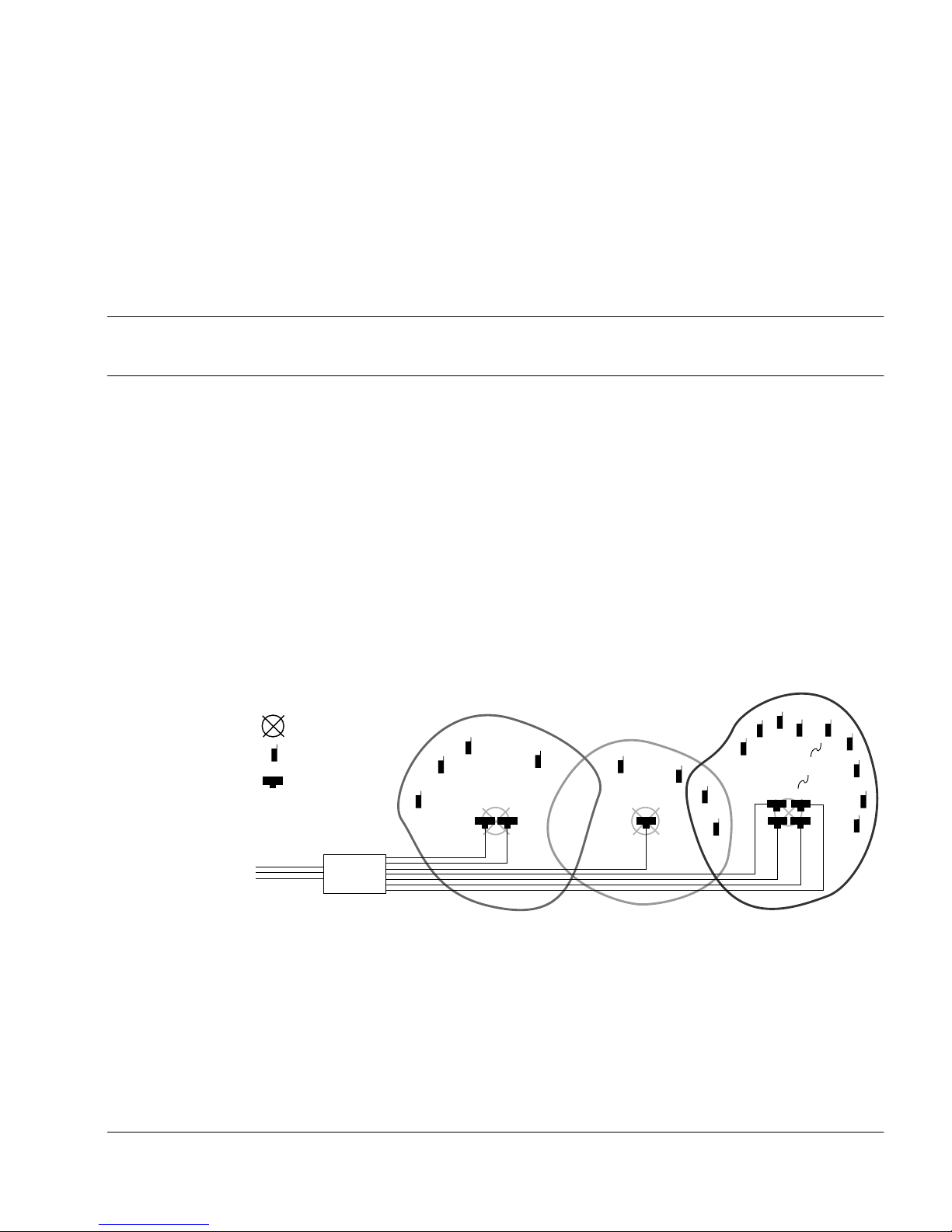
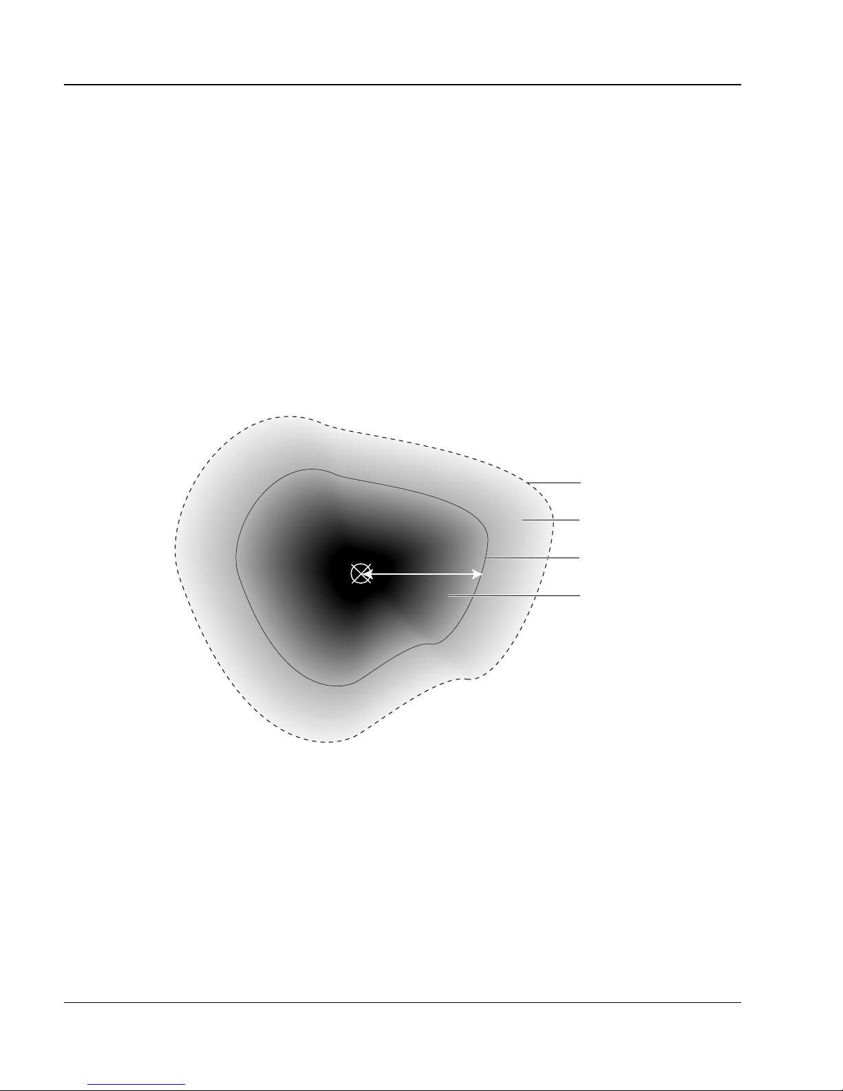
Cell boundary values
The strength of the radio signal the portable receives decreases as you walk
away from the cell center. As shown in Figure 10 on page 18, the cell
boundary is the f arthest place from the cell center whe re you hear a go od radio
signal.
Links can be made outside the cell boundary but the audio quality of the link
is poor . The link drops when the portable and the Base Station a re too far apa rt.
The range from the cell center to the cell boundary, or the distance to a
potential ce ll center from a critica l point, is determin ed using the cell bound ary
value and the CDT. The CDT uses a default v a lue for the cell bounda ry va lue.
This value can be reset to suit your pla nning needs.
Figure 10 : Cell boundary terminology
cell center
range
link drops
poor audio quality
cell boundary
good audio quality
553-3601-106 Standard 2.00 September 1996

1
Companion Deployment Tool Pag e 19 of 102
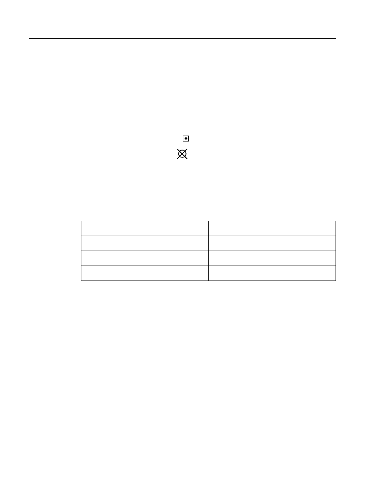
Use Table 4, “: Cell boundary v alu es,” to determ ine which cell boun dary va lue
you should use.
Table 4 : Cell boundary values
Indoors
(with office)
-70 dBm -73 dBm -75 dBm
Indoors
(without office)
Note: You can set the cell boundary values into your portable. Refer to your
portable’s user guide for instructions.
Use -73 dBm as the cell boundary value if there are no, or only a few, users’
off ices within the prospective cel l. Use -70 dBm as the cell boundary value if
a group of offices is withi n the cell. Use -75 dBm for outdoor areas tha t are
served by indoor Base Station s. F or outdoor areas that cannot be reached by
an indoor Base Stat ion, see “Covering outdoor areas” on page 26.
Note: An off ice is any ar ea where u sers can make and receive call s on their
portab les wh il e s it t in g at th e ir de s k s or in th ei r cub i cl es.
Using the CDT to deter m ine cell boundaries
Y ou us e the CDT and a portable to determin e the radio range. Listen to the tone
the porta ble mak es while wa lking b riskly a way f rom the CDT transcei ve r unti l
the tone changes, indicating the cell boundary value. When the portable
detects the cell boundary value, the distance between you and the CDT
transcei ve r is t he ra nge. Fo r more i nformatio n, see “ Int erpr eting the porta ble’s
tones” on page 16.
Outdoors
Note: The farther you move away from the CDT transceiver, the more
Measuri ng ra di o range
negative the number you read. For instance, a reading of -66 indicates
that yo u ar e fa rth er f ro m the tran s c eiver th an a re ad i n g o f -50.
Note 1: When you are determining the range, hold the portable
approximately 40 t o 50 in. (1.0 to 1.3 m) fr om the floor. Do not
bring it too close to walls or other obj ects.
Meridian Companion Site Planning Reference Manual

1
Page 20 of 102 Companion Deployment Tool
Note 2: Walk brisk ly as you listen to the tones . This is necessary to get
an av erage reading of the link’s signal strength.
1. S tand at a position ne ar the CDT where the portable displays a signal
strength that is at least 10 dB stronger than the cell boundary value and
where you hear a continuous tone.
2. Walk briskly away from the CDT transceiver until the tone changes.
Stop and record your position on the floor plan with a small x.
Note: It is the location where the tone first changes that is important. The
signal strength value on the display may fluctuate and the tone may
change after you stop walking.
553-3601-106 Standard 2.00 September 1996

Site planning basics
The basics of planning a site
Planning a site involves the following tasks:
• determining site-specific information
• planning for outdoor coverage (as required)
• surveying the site
• determining how much equipment is required to cover the site
• reviewing your work
“Planning a Sample Site” on page 43 uses an example to describe these tasks .
Methods and examples for surveying more detailed sites are described in
“Planning complex sites” on page 57.
Page 21 of 102
You will use one or more of the follo wing surve ying methods in your site
survey:
• single floor
• mult ip le adjacent floors
• subseque nt system install ation
• high portabl e density area
• multiple systems installation
Meridian Companion Site Planning Reference Manual

2
Page 22 of 102 Site planning basics
Site plannin g prerequisit es
Before you go to the site, make sure that you have the following:
• a working CDT and portable telephone
• any keys needed for secured areas wher e you re quire coverage
• copies of the site floor plan (one working and one clean copy)
• a pencil, an er aser, a ruler an d color ed p ens
• a page from the appropriate Compani on P r ovisioning Record
• any required safety equipment, such as a hard hat or safety glasses
•the appropriate Companion installation guide
Required site information
You need the foll owing infor mation to accurately pla n a site:
• the name and telephone number of the si te contact
• the number of portables, the boundaries of the coverage area, and the
proposed Companion system
• the location of the telephone switching room
• whether the custom er requires outdoor coverage
• whether the custom er wants to reduce th e number of Ba se St ations by
not covering areas that re quire more intensive coverage, such as
restrooms, stai rw ells or baseme nts
• whether there is another system on the site
• whether users have a desk telephone in their office
Note: An of fice is an y are a whe re u se rs c an m ak e and rec ei v e ca ll s on
their portables while sitting at their desks or in their cubicles.
• how to get access to s ecure d are as
• whether it is acceptable to install Base Stations on the ceiling
• whether the Base Stations must be hidden from view
553-3601-106 Standard 2.00 September 1996

2
Site plann ing basics Page 23 of 10 2
You also need to determin e the mobili ty of the users. For instanc e, you need to
know whether the user s mov e from cell to cell or whether the y will alway s be
within one cell.
Use one cop y of the floor pl an as a w orking c opy to i dentif y critica l points , cell
centers a nd cell bound ari es. Us e the ot her copy as a cle an copy and atta ch it t o
the site Provisioning Record for the install er, customer, maintenance and
anyone else who needs to see your work.
Note: The floor pla ns should include a scale. The scale is used for the range
for outdoo r c ove rage and to c heck wi ring di stan ces from the Con trolle r
to the Base S tations.
Meridian Companion Site Planning Reference Manual
2
Page 24 of 102 Site planning basics
Labeling a floor plan
Clearly mark info rmation on the floor plans during planning. Your customer,
the sales group, the installer and maintenance personnel need to read these
floor plans.
Use a different color for each cell. Use the same color for each cell center and
its correspondi ng cell bo undaries. Indicate th e informat ion on the fl oor plan as
follows:
• cri tical p oi n ts—mark on the fl oo r plan
• cell centers—mark on the floor plan. Label each cell center xCn
where x is the fl oo r an d n is the next sequential cell center.
For exa mple, label a cell center on th e second floor 2C4. The 2 tells you
that the cell center is on the sec ond floor; th e 4 tells you that this cell is
the fourth cell in sequence in the planning process.
Table 5 : Example cell labels
second floo r 2C4, 2C5
first floor or outdoors 1C1, 1C2, 1C3
basement -1C6, -1C7
Floor Cell label
553-3601-106 Standard 2.00 September 1996
 Loading...