

Page 1

Meridian 1
This Nortel documentation is protected by copyright. It may not be copied in any form or medium except
puruant to the Nortel License to Copy Documentation ("License"). If a License has been purchased, it will
be enclosed with this copy of Nortel documents.
Option 11C Compact
Technical Reference Guide
Document Number: 553-3121-100
Document Release: Standard 2.0
Date: September , 1998
Year Publish FCC TM
© 1997, 1998
All rights reserved
Printed in Canada
Information is subject to change without notice. Nortel reserves the right to make changes in design or
components as progress in engineering and manufacturing may warrant. This equipment has been tested and
found to comply with the limits for a Class A digital device pursuant to Part 15 of the FCC rules.
Meridian 1, Option 11C and Compact are trademarks of Nortel (Northern Telecom).
Meridian 1 Option 11C Compact Technical Refer ence Guide
Page 2

Revision history
September 1998
Release 2.0, Standard
November, 1997
Release 1.0, Standard
Meridian 1 Option 11C Compact Technical Reference Guide
Page 3

553-3121-100 Standard 2.0 September 1998
Page 4

Contents
i
About this guide . . . . . . . . . . . . . . . . . . . . . . . . . . . vii
Chapter 1 — Provisioning . . . . . . . . . . . . . . . . . . . . . 1
Introduction . . . . . . . . . . . . . . . . . . . . . . . . . . . . . . . . . . . . . . . . . . . . . 1
Provisioning a new system . . . . . . . . . . . . . . . . . . . . . . . . . . . . . . . . . . 1
Forecasting trunk and line growth . . . . . . . . . . . . . . . . . . . . . . . . . . . . 2
Calculati ng number of trunks required . . . . . . . . . . . . . . . . . . . . . . 2
Calculating number of lines required . . . . . . . . . . . . . . . . . . . . . . . 2
Worksheet A: Trunk Forecast . . . . . . . . . . . . . . . . . . . . . . . . . . . . . 3
Worksheet B: Line forecast . . . . . . . . . . . . . . . . . . . . . . . . . . . . . . . 4
Provisioning conference channels . . . . . . . . . . . . . . . . . . . . . . . . . . . . 5
Conference channels . . . . . . . . . . . . . . . . . . . . . . . . . . . . . . . . . . . . 5
Assigning equipment and preparing equipment summary . . . . . . . . . . 5
Worksheet C: System cabinet requirements . . . . . . . . . . . . . . . . . . 6
List the card slot assignments . . . . . . . . . . . . . . . . . . . . . . . . . . . . . 7
Worksheet D: Card Slot Assignments . . . . . . . . . . . . . . . . . . . . . . . 9
Chapter 2 — Transmission parameters . . . . . . . . . 11
Introduction . . . . . . . . . . . . . . . . . . . . . . . . . . . . . . . . . . . . . . . . . . . . . 11
Transmission . . . . . . . . . . . . . . . . . . . . . . . . . . . . . . . . . . . . . . . . . . . . 11
Loss Plan . . . . . . . . . . . . . . . . . . . . . . . . . . . . . . . . . . . . . . . . . . . . . 11
Insertion loss limits . . . . . . . . . . . . . . . . . . . . . . . . . . . . . . . . . . . . . 17
Input Impedance and Balance Impedance . . . . . . . . . . . . . . . . . . . . . . 19
Return Loss . . . . . . . . . . . . . . . . . . . . . . . . . . . . . . . . . . . . . . . . . . . . . 20
Transhybrid Loss . . . . . . . . . . . . . . . . . . . . . . . . . . . . . . . . . . . . . . . . . 21
Idle Channel Noise . . . . . . . . . . . . . . . . . . . . . . . . . . . . . . . . . . . . . . . . 22
Meridian 1 Option 11C Compact Technical Refer ence Guide
Page 5

ii Contents
Impulse Noise . . . . . . . . . . . . . . . . . . . . . . . . . . . . . . . . . . . . . . . . . 22
Total distortion including quantization distortion . . . . . . . . . . . . . . . . 25
Spurious in-band signal . . . . . . . . . . . . . . . . . . . . . . . . . . . . . . . . . . . . 26
Spurious out-of-band signal . . . . . . . . . . . . . . . . . . . . . . . . . . . . . . . . . 26
Discrimination against out-of-band signals . . . . . . . . . . . . . . . . . . . . . 26
Intermodulation . . . . . . . . . . . . . . . . . . . . . . . . . . . . . . . . . . . . . . . . . . 26
Group Delay . . . . . . . . . . . . . . . . . . . . . . . . . . . . . . . . . . . . . . . . . . . . . 27
Absolute group delay . . . . . . . . . . . . . . . . . . . . . . . . . . . . . . . . . . . 27
Group delay distortion . . . . . . . . . . . . . . . . . . . . . . . . . . . . . . . . . . 27
Longitudinal balance . . . . . . . . . . . . . . . . . . . . . . . . . . . . . . . . . . . . . . 28
Crosstalk . . . . . . . . . . . . . . . . . . . . . . . . . . . . . . . . . . . . . . . . . . . . . . . 29
Chapter 3 — Spares planning . . . . . . . . . . . . . . . . . . 31
Introduction . . . . . . . . . . . . . . . . . . . . . . . . . . . . . . . . . . . . . . . . . . . . . 31
Definitions and assumptions . . . . . . . . . . . . . . . . . . . . . . . . . . . . . . . . 31
Calculating spares requirements . . . . . . . . . . . . . . . . . . . . . . . . . . . . . 33
Failure rates . . . . . . . . . . . . . . . . . . . . . . . . . . . . . . . . . . . . . . . . . . . . . 35
NFT values . . . . . . . . . . . . . . . . . . . . . . . . . . . . . . . . . . . . . . . . . . . . . . 37
Chapter 4 — Power supplies . . . . . . . . . . . . . . . . . . .39
Introduction . . . . . . . . . . . . . . . . . . . . . . . . . . . . . . . . . . . . . . . . . . . . . 39
Features . . . . . . . . . . . . . . . . . . . . . . . . . . . . . . . . . . . . . . . . . . . . . . . . 39
Dimensions and weight . . . . . . . . . . . . . . . . . . . . . . . . . . . . . . . . . . 39
Power Supply features . . . . . . . . . . . . . . . . . . . . . . . . . . . . . . . . . . 39
Voltage . . . . . . . . . . . . . . . . . . . . . . . . . . . . . . . . . . . . . . . . . . . . . . 39
Ringing Generator . . . . . . . . . . . . . . . . . . . . . . . . . . . . . . . . . . . . . . 40
Power supply LED . . . . . . . . . . . . . . . . . . . . . . . . . . . . . . . . . . . . . 40
Under-voltage . . . . . . . . . . . . . . . . . . . . . . . . . . . . . . . . . . . . . . . . . 40
Overvoltage . . . . . . . . . . . . . . . . . . . . . . . . . . . . . . . . . . . . . . . . . . . 42
Temperature sensor . . . . . . . . . . . . . . . . . . . . . . . . . . . . . . . . . . . . . 42
Power Fail Transfer (PFT) operation . . . . . . . . . . . . . . . . . . . . . . . . . . 43
Commercial Power Backup . . . . . . . . . . . . . . . . . . . . . . . . . . . . . . . . . 44
553-3121-100 Standard 2.0 September 1998
Page 6

Contents iii
Chapter 5 — NTMW01 Small System Controller . . 45
Introduction . . . . . . . . . . . . . . . . . . . . . . . . . . . . . . . . . . . . . . . . . . . . . 45
NTMW01 Small System Controller card . . . . . . . . . . . . . . . . . . . . . . . 45
Chapter 6 — SDI ports . . . . . . . . . . . . . . . . . . . . . . . 49
Introduction . . . . . . . . . . . . . . . . . . . . . . . . . . . . . . . . . . . . . . . . . . . . . 49
Small System Controller (SSC) card . . . . . . . . . . . . . . . . . . . . . . . . . . 49
NTMW10 Fiber Receiver card . . . . . . . . . . . . . . . . . . . . . . . . . . . . . . . 50
Parameter settings . . . . . . . . . . . . . . . . . . . . . . . . . . . . . . . . . . . . . . 50
Connection to external equipment . . . . . . . . . . . . . . . . . . . . . . . . . . 51
Chapter 7 — Meridian Modular Telephones . . . . . . 53
Functional description . . . . . . . . . . . . . . . . . . . . . . . . . . . . . . . . . . . . . 53
Peripheral equipment requirements . . . . . . . . . . . . . . . . . . . . . . . . . 53
General description . . . . . . . . . . . . . . . . . . . . . . . . . . . . . . . . . . . . . 54
Physical characteristics . . . . . . . . . . . . . . . . . . . . . . . . . . . . . . . . . . 59
Features and options matrix . . . . . . . . . . . . . . . . . . . . . . . . . . . . . . . 62
Optional equipment . . . . . . . . . . . . . . . . . . . . . . . . . . . . . . . . . . . . . 63
Specifications . . . . . . . . . . . . . . . . . . . . . . . . . . . . . . . . . . . . . . . . . . . . 68
Environmental and safety considerations . . . . . . . . . . . . . . . . . . . . 68
Line engineering . . . . . . . . . . . . . . . . . . . . . . . . . . . . . . . . . . . . . . . 68
Local alerting tones . . . . . . . . . . . . . . . . . . . . . . . . . . . . . . . . . . . . . 69
Power requirements . . . . . . . . . . . . . . . . . . . . . . . . . . . . . . . . . . . . . 70
Meridian Programmable Data Adapter . . . . . . . . . . . . . . . . . . . . . . 77
Chapter 8 — M2250 Attendant Console. . . . . . . . . . 79
Introduction . . . . . . . . . . . . . . . . . . . . . . . . . . . . . . . . . . . . . . . . . . . . . 79
Description . . . . . . . . . . . . . . . . . . . . . . . . . . . . . . . . . . . . . . . . . . . . . . 79
Features . . . . . . . . . . . . . . . . . . . . . . . . . . . . . . . . . . . . . . . . . . . . . . 79
Physical details . . . . . . . . . . . . . . . . . . . . . . . . . . . . . . . . . . . . . . . . 81
Keyboard layout . . . . . . . . . . . . . . . . . . . . . . . . . . . . . . . . . . . . . . . 83
Display screen messages . . . . . . . . . . . . . . . . . . . . . . . . . . . . . . . . . 86
Connections . . . . . . . . . . . . . . . . . . . . . . . . . . . . . . . . . . . . . . . . . . . 89
Local console controls . . . . . . . . . . . . . . . . . . . . . . . . . . . . . . . . . . . 89
Busy Lamp Field/Console Graphics Module Busy Lamp Field/Console
Graphics Module . . . . . . . . . . . . . . . . . . . . . . . . . . . . . . . . . . . . . . . 90
Meridian 1 Option 11C Compact Technical Refer ence Guide
Page 7

iv Contents
Chapter 9 — NTMW05 Digital Line Card . . . . . . . . . .93
Description . . . . . . . . . . . . . . . . . . . . . . . . . . . . . . . . . . . . . . . . . . . . . . 93
Physical . . . . . . . . . . . . . . . . . . . . . . . . . . . . . . . . . . . . . . . . . . . . . . 93
Functional . . . . . . . . . . . . . . . . . . . . . . . . . . . . . . . . . . . . . . . . . . . . 94
Technical summary . . . . . . . . . . . . . . . . . . . . . . . . . . . . . . . . . . . . . . . 95
Power requirements . . . . . . . . . . . . . . . . . . . . . . . . . . . . . . . . . . . . . 95
Foreign and surge voltage protections . . . . . . . . . . . . . . . . . . . . . . 95
Chapter 10 — NTMW06 Analog Line Card . . . . . . . .97
Description . . . . . . . . . . . . . . . . . . . . . . . . . . . . . . . . . . . . . . . . . . . . . . 97
Physical . . . . . . . . . . . . . . . . . . . . . . . . . . . . . . . . . . . . . . . . . . . . . . 98
Functional . . . . . . . . . . . . . . . . . . . . . . . . . . . . . . . . . . . . . . . . . . . . 99
Technical summary . . . . . . . . . . . . . . . . . . . . . . . . . . . . . . . . . . . . . . . 100
Analog line interface . . . . . . . . . . . . . . . . . . . . . . . . . . . . . . . . . . . . 100
Power requirements . . . . . . . . . . . . . . . . . . . . . . . . . . . . . . . . . . . . . 102
Foreign and surge voltage protections . . . . . . . . . . . . . . . . . . . . . . 102
Overload level . . . . . . . . . . . . . . . . . . . . . . . . . . . . . . . . . . . . . . . . . 102
Chapter 11 — NTMW07 Trunk/Line Card . . . . . . . .103
Introduction . . . . . . . . . . . . . . . . . . . . . . . . . . . . . . . . . . . . . . . . . . . . . 103
Description . . . . . . . . . . . . . . . . . . . . . . . . . . . . . . . . . . . . . . . . . . . . . . 103
Trunk types supported . . . . . . . . . . . . . . . . . . . . . . . . . . . . . . . . . . . 104
Electrical characteristics . . . . . . . . . . . . . . . . . . . . . . . . . . . . . . . . . 105
Physical characteristics . . . . . . . . . . . . . . . . . . . . . . . . . . . . . . . . . . 106
Slot assignments . . . . . . . . . . . . . . . . . . . . . . . . . . . . . . . . . . . . . . . 106
Power Fail Transfer . . . . . . . . . . . . . . . . . . . . . . . . . . . . . . . . . . . . . 108
Power requirements . . . . . . . . . . . . . . . . . . . . . . . . . . . . . . . . . . . . . 109
Environmental specifications . . . . . . . . . . . . . . . . . . . . . . . . . . . . . 109
Foreign and surge voltage protection . . . . . . . . . . . . . . . . . . . . . . . 109
Release control . . . . . . . . . . . . . . . . . . . . . . . . . . . . . . . . . . . . . . . . 109
PAD switching . . . . . . . . . . . . . . . . . . . . . . . . . . . . . . . . . . . . . . . . 110
Application . . . . . . . . . . . . . . . . . . . . . . . . . . . . . . . . . . . . . . . . . . . . . . 112
Loop start operation . . . . . . . . . . . . . . . . . . . . . . . . . . . . . . . . . . . . 112
Ground start operation . . . . . . . . . . . . . . . . . . . . . . . . . . . . . . . . . . 112
Direct Inward Dial operation . . . . . . . . . . . . . . . . . . . . . . . . . . . . . 112
Tie Two-way Dial Repeating operation . . . . . . . . . . . . . . . . . . . . . 113
553-3121-100 Standard 2.0 September 1998
Page 8

Contents v
Tie Outgoing Automatic Incoming Dial operation . . . . . . . . . . . . . 113
Recorded Announc ement operation . . . . . . . . . . . . . . . . . . . . . . . . 113
Paging operation . . . . . . . . . . . . . . . . . . . . . . . . . . . . . . . . . . . . . . . 114
Chapter 12 — NTMW44 Universal Trunk Card . . . 115
Introduction . . . . . . . . . . . . . . . . . . . . . . . . . . . . . . . . . . . . . . . . . . . . . 115
Description . . . . . . . . . . . . . . . . . . . . . . . . . . . . . . . . . . . . . . . . . . . . . . 115
Trunk types supported . . . . . . . . . . . . . . . . . . . . . . . . . . . . . . . . . . . 116
Electrical characteristics . . . . . . . . . . . . . . . . . . . . . . . . . . . . . . . . . 117
Physical characteristics . . . . . . . . . . . . . . . . . . . . . . . . . . . . . . . . . . 118
Slot assignments . . . . . . . . . . . . . . . . . . . . . . . . . . . . . . . . . . . . . . . 118
Power requirements . . . . . . . . . . . . . . . . . . . . . . . . . . . . . . . . . . . . . 119
Environmental specifications . . . . . . . . . . . . . . . . . . . . . . . . . . . . . 120
Foreign and surge voltage protection . . . . . . . . . . . . . . . . . . . . . . . 120
Release control . . . . . . . . . . . . . . . . . . . . . . . . . . . . . . . . . . . . . . . . 120
PAD switching . . . . . . . . . . . . . . . . . . . . . . . . . . . . . . . . . . . . . . . . . 120
Application . . . . . . . . . . . . . . . . . . . . . . . . . . . . . . . . . . . . . . . . . . . . . . 123
Loop start operation . . . . . . . . . . . . . . . . . . . . . . . . . . . . . . . . . . . . . 123
Ground start operation . . . . . . . . . . . . . . . . . . . . . . . . . . . . . . . . . . . 123
Direct Inward Dial operation . . . . . . . . . . . . . . . . . . . . . . . . . . . . . . 123
Tie Two-way Dial Repeating operation . . . . . . . . . . . . . . . . . . . . . 124
Tie Outgoing Automatic Incoming Dial operation . . . . . . . . . . . . . 124
Recorded Announc ement operation . . . . . . . . . . . . . . . . . . . . . . . . 124
Paging operation . . . . . . . . . . . . . . . . . . . . . . . . . . . . . . . . . . . . . . . 125
Chapter 13 — NTMW04 1.5 Mb DTI/PRI . . . . . . . . . 127
Introduction . . . . . . . . . . . . . . . . . . . . . . . . . . . . . . . . . . . . . . . . . . . . . 127
Functional description . . . . . . . . . . . . . . . . . . . . . . . . . . . . . . . . . . . . . 127
Physical description . . . . . . . . . . . . . . . . . . . . . . . . . . . . . . . . . . . . . . . 128
LEDs . . . . . . . . . . . . . . . . . . . . . . . . . . . . . . . . . . . . . . . . . . . . . . . . 128
Foreign and surge voltage protection . . . . . . . . . . . . . . . . . . . . . . . 129
Architecture . . . . . . . . . . . . . . . . . . . . . . . . . . . . . . . . . . . . . . . . . . . . . 130
Signaling interface . . . . . . . . . . . . . . . . . . . . . . . . . . . . . . . . . . . . . . 130
Interconnection . . . . . . . . . . . . . . . . . . . . . . . . . . . . . . . . . . . . . . . . 130
Digital pad . . . . . . . . . . . . . . . . . . . . . . . . . . . . . . . . . . . . . . . . . . . . 130
D-Channel Interface . . . . . . . . . . . . . . . . . . . . . . . . . . . . . . . . . . . . 131
Meridian 1 Option 11C Compact Technical Refer ence Guide
Page 9

vi Contents
Clock controller interface . . . . . . . . . . . . . . . . . . . . . . . . . . . . . . . . 131
Mode of operation . . . . . . . . . . . . . . . . . . . . . . . . . . . . . . . . . . . . . . 132
Chapter 14 — NTMW50 RS232 Service Module
Assembly . . . . . . . . . . . . . . . . . . . . . . . . . . . . . . . . . .133
Introduction . . . . . . . . . . . . . . . . . . . . . . . . . . . . . . . . . . . . . . . . . . . . . 133
Functional description . . . . . . . . . . . . . . . . . . . . . . . . . . . . . . . . . . . . . 133
Switch and LED . . . . . . . . . . . . . . . . . . . . . . . . . . . . . . . . . . . . . . . 134
Chapter 15 — Fiber optic cable and interfaces . . . 135
Introduction . . . . . . . . . . . . . . . . . . . . . . . . . . . . . . . . . . . . . . . . . . . . . 135
Fiber optic cable interfaces . . . . . . . . . . . . . . . . . . . . . . . . . . . . . . . . . 135
NTDK22 Fiber Expansion da ughter board . . . . . . . . . . . . . . . . . . . 135
NTMW10 Fiber Receiver card . . . . . . . . . . . . . . . . . . . . . . . . . . . . 135
Plastic Fiber Optic cable . . . . . . . . . . . . . . . . . . . . . . . . . . . . . . . . . 136
Environment . . . . . . . . . . . . . . . . . . . . . . . . . . . . . . . . . . . . . . . . . . 136
553-3121-100 Standard 2.0 September 1998
Page 10

viii
vii
About this guide
This Technical refer ence guide c ontains det aile d t echni cal i nforma tion a bout
the Meridian 1 Option 11C Compact system. It includes such things as :
• circuit cards information
• spares planning
• SDI ports information
• transmission parameters
• Meridian modul ar telephone sets
• M2250 attendant console
Meridian 1 Option 11C Compact Technical Refer ence Guide
Page 11

viii About this guide
553-3121-100 Standard 2.0 September 1998
Page 12

10
g
Page 1 of 136
Chapter 1 — Provisionin
Introduction
This chapter out lines the procedures required to determine equip ment
requirements.
Provisioning a new system
Provisioning a new system consists of:
• Defining and forecasting growth.
• Calculating num ber of trunks required.
• Calculating num ber of lines required.
• Assigning equipment and preparing an equipment summary.
Meridian 1 Option 11C Compact Technical Refer ence Guide
Page 13

Page 2 o f 136 Chapter 1 — Provisioning
Forecasting trunk and line growth
The first step i n provisioni ng a new system is to forecast t he number of trunks
and lines require d at two-year and five-year interva ls .
The number of t runks a nd line s re quired whe n the system i s pla ced i n serv ice
(cutover) is determined by the customer. If the c us tom er is unable to provide
a two-year and five-ye ar growth forecast, then an estimate of an nual growth
is used to e stimate the number o f trunks and line s required a t the two-y ear and
five-year intervals.
Calculating number of trunks required
Enter the quantity of each type of trunk required in Worksheet A. This
determines t he number of trunk cards required at cut over, two-year, and
five-year intervals.
Calculating number of lines required
Enter the quantity of each type of analog and digital line required in
Worksheet B. This determines the number of Meridian Digital Telephone
TNs and Analog (500/2500 ty pe) TNs required at cutover, two-year, and
five-year intervals.
553-3121-100 Standard 2.0 September 1998
Page 14

Worksheet A: Trunk Forecast
Customer: ________________________________
Date: _________________
NTMW07 Trunk/Line Card Forecast Worksheet
Trunks Cutover 2 years 5 years
2-way
1-wa y in
1-wa y o ut
DID
Tie
CCSA
InWATS
OutWATS
FX
Private line
Dial dictation
Chapter 1 — Provisioning Page 3 of 136
Paging
RAN
AIOD
CO
Total
= Number of NTMW07 cards needed
Multiply number of NTMW07 by 4
Each NTMW07 Trunk/Line card is provides four trunk TNs, four analog line TNs and one power fail
Note:
transfer cir cu it. See "Chapt er 11 —NTMW 07 Trunk/Line Card"
= Analog lines available
Divide Total by 4
for details.
Meridian 1 Option 11C Compact Technical Refer ence Guide
Page 15

Page 4 o f 136 Chapter 1 — Provisioning
Worksheet B: Line forecast
Customer: ________________________________
Date: _________________
Digital Line TN Forecast Worksheet_
Digital Telephone Line TNs
Attendant Con sole TNs (i ncluding TNs
for power, see
Digital Telephone Line TNs
= number of NTMW05 cards needed
Note:
See "Chapter 8 —M2250 Attendant Console" for power ing options.
Note
) See
Divide total by 24
Note.
Total
Quantity
at Cutover
Analog Line TN Forecast Worksheet
Quantity
Analog Telephone Line TNs
Analog Telephone line
(500/2500-type) TNs
Total
Minus 4 x number of NTMW07 cards in
system
at Cutover
Quantity
in 2 years
Quantity
in 2 years
Quantity
in 5 years
Quantity
in 5 years
= additional analog TNs needed
= number of NTMW06 cards needed
Note:
transfer circuit. See "Chapter 11 —NT MW07 Tr un k/ Line Card "
553-3121-100 Standard 2.0 September 1998
Divide additional TNs by 16
Each NTMW 07 Tru nk/Line card is provides four trunk TNs, four analog line TNs and one power fail
for details.
Page 16

Chapter 1 — Provisioning Page 5 of 136
y
Provision ing conference channels
Conference channels
The conference function is provided by the NTMW01 Small Syste m
Controller (SSC) card. Two conference circuits are always active, a third
becomes active when the expansion cabinet is equipped.
Each conference cir cuit supports 16 conferees. Therefore the SSC card
supports a total of 32 conferees.
The Fiber Expansion Daughterboard supports an a dditional conference
circuit. Therefore a total of 48 conferees are supported when the SSC card is
equipped with a Fiber Expansion Daughterboard.
Assigning equipment and preparing equipment summar
Use Worksheet C to record the equipment requirements for the complete
system at c utov er. Ass ign the e quipment. The eq uipment s umm ary may h ave
to be updated as a result of assignment procedures.
Use the finaliz ed equi pment summar y (Workshee t C) to ord er th e equip ment
for the system.
Meridian 1 Option 11C Compact Technical Refer ence Guide
Page 17

Page 6 o f 136 Chapter 1 — Provisioning
Worksheet C: System cabinet requirements
Customer:________________________________________
Date: ______________
Prepare one workshe et for t he syst em at cutover, 2- year , and 5 -year in terval s.
PE Card Ca lculati o ns Worksheet
Number of NTMW05 Digital Line cards
Number of NTMW06 Analog Line cards
Number of NTMW07 Trunk/Line cards
Cutover 2 years 5 years
Number of NTMW04 DTI cards (See
Note:
See "Chapter 9 —NTMW05 Digital Line Card" for information about the DTI card.
Note
)
Total
553-3121-100 Standard 2.0 September 1998
Page 18
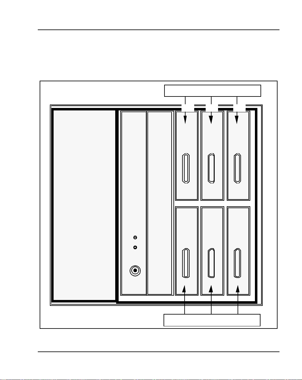
List the card slot assignments
NTMW05, NTMW06
Refer to Figure 1 and Figure 2 for card slot ass ignm ents and list them on
Worksheet D.
Figure 1
Card slot assignments in Main Cabi net
Main Cabinet
Chapter 1 — Provisioning Page 7 of 136
NTMW04, NTMW05, NTMW06, NTMW07
1&2 3&4 5&6
NTMW11
Power Supply
NTMW01
SSC
NTMW02
V Mail
CPU
CPU MMail
PE
Card
PE
Card
PE
Card
789
PE
Card
PE
Card
PE
Card
Meridian 1 Option 11C Compact Technical Refer ence Guide
Page 19
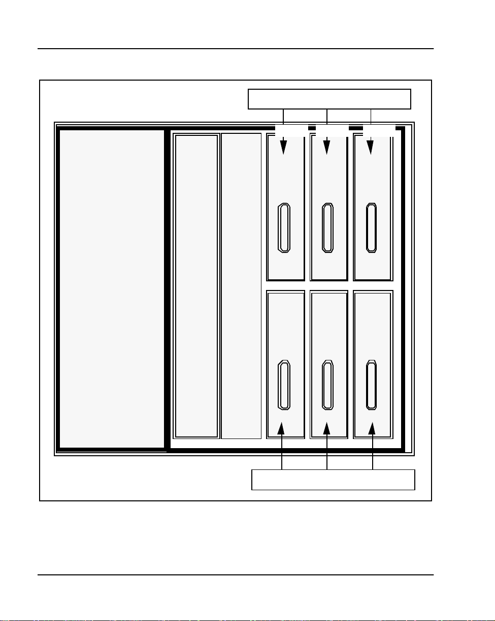
Page 8 o f 136 Chapter 1 — Provisioning
PE
Card
PE
Card
NTMW05, NTMW 06
Figure 2
Card slot assignments in Expansion Cabinet
Expansion Cabinet
NTMW05, NTMW06, NTMW07
11&12 13&14 15&16
NTMW11
Power Supply
NTMW10
Fiber
Receiver
Empty
Slot
PE
Card
PE
Card
17 18 19
PE
Card
PE
Card
553-3121-100 Standard 2.0 September 1998
Page 20

Chapter 1 — Provisioning Page 9 of 136
Worksheet D: Card Slot Assignments
Main and Expansion
Cabinet
Card Assignment
Slot
Number
1 & 2 11 & 12
3 & 4 13 & 14
5 & 6 15 & 16
7 17
8 18
919
10 Mail 20 Not used
Card Type
Main and Expansion
Cabinet
Card Assignment
Slot
Number
Card Type
Meridian 1 Option 11C Compact Technical Refer ence Guide
Page 21

Page 10 of 136 Chapter 1 — Provisioning
553-3121-100 Standard 2.0 September 1998
Page 22

30
Page 11 of 136
Chapter 2 — Transmission parameters
Introduction
The Meridian 1 Opti on 11C Com p act system uses µ-Law companding to
convert signals from analog to digital and from digital to analog.
Transmission characteristics are given in this chapter. Except where indicated
otherwise, the design objectives given are met when measured between 2
wire and 4 wire analog input and output interfaces terminated with their
nominal impedance.
The reference frequency is 1024 Hz. The reference level is -10 dBmO (as an
alternative a reference level of 0 dBmO may be used).
Transmission
Loss Plan
Insertion loss
The insertion loss of a private branch exchange (PBX) conn ection is defined
as the differen ce between the power del ivered from the (test) re ference source
into the input port and the power at the output port. For insertion loss tests
both the signal source and the measurement ins trum ent have impedances of
600 ohms. The test frequency is 1024 Hz.
The insertion losses between various Peripheral Equipment (PE) ports are
connection - specific in order to be compatible wit h end-to-end network
connection loss requirements. The Op tion 11C Compact loss specifications
are in ag r eement with North American standards, which are for mulated to
provide satisfactory end-to-end performance for connections within private
networks and between private and public networks.
Meridian 1 Option 11C Compact Technical Refer ence Guide
Page 23

Page 12 of 136 Chapter 2 — Transmission parameters
The los s plan strategy fo r PE combines electrical loss with terminal acoustic
parameters for optimum transmission performance. For this reason, some
connections have asymmetrical loss in order to conform with network loss
plans. This asymmetry is resolved at a remote point (another switch) in the
overall connection.
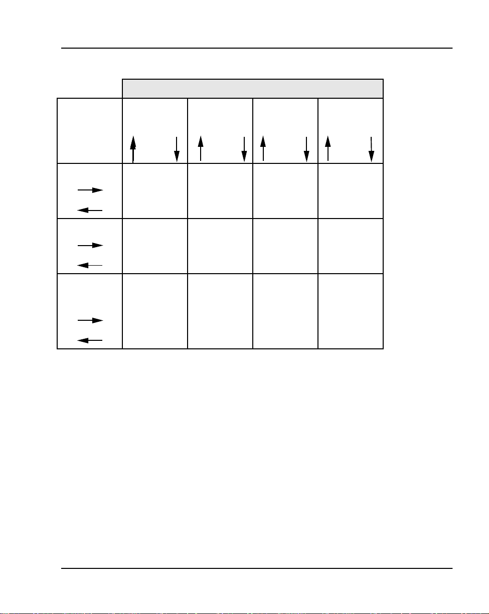
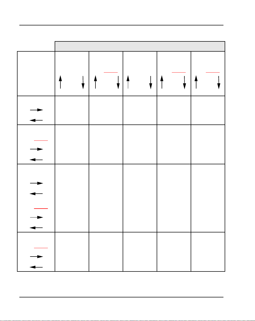
Tables 1
, 2 and 3 provide loss values measured in decibels (dB) for
connections between:
• PE ports (lines and trunks)
• Digital ports (PRI or DTI)
Tables 1
, 2 and 3 are in matrix format; note the direction of the arrows when
searching for a lo ss v alue.
553-3121-100 Standard 2.0 September 1998
Page 24
Chapter 2 — Transmission parameters Page 13 of 136
Table 1
Insertion Loss from PE Ports to PE Ports (measured in dB)
PE Ports
PE Ports
500/2500 Line
Digital Line
CO/FX/WATS
Loop Tie
Trunk
500/2500 Line Digital
Line
6
6
2.5
0
3.5
2.5
0
0
0
-3.5
4 Wire (ESN)
E&M Trunk
0
-0.5
CO/FX/WATS
Loop Tie
Tr unk
0.5
0.5
Meridian 1 Option 11C Compact Technical Refer ence Guide
Page 25
Page 14 of 136 Chapter 2 — Transmission parameters
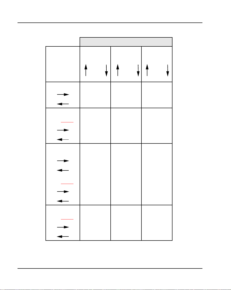
Table 2
Insertion Loss Digital Ports T o PE Ports (measured in dB)
PE Ports
Digital Ports
Tie Trunk
Satell it e Tie
Trunk
(See Note 1
CO/FX/WATS
Loop Tie Trunk
Toll Office
(See Note 2
)
)
500/2500 Line Digital
Line
8.5
2.5
0.5
6
2.5
-3
2.5
2
4.5
CO/FX/WATS
2.5
0
-0.5
0
0.5
-1
Loop Tie
Tr unk
-2.5
-0.5
-0.5
8.5
2.5
Primary Rate
Interface (PRI )
(See Note 3
553-3121-100 Standard 2.0 September 1998
)
6.5
3.5
6
6
5.5
0
2.5
0
0.5
-2.5`
Page 26

Chapter 2 — Transmission parameters Page 15 of 136
Notes to Table 2
Note 1: A satellite tie trunk connects a satellite or tributary PBX to a
main PBX. A t ributary PBX doe s not have its own directory number for
incom in g calls.
Note 2: The toll office designation is for a trunk to an office in the
public swit ched network wit h a higher rank tha n the local office (clas s 5).
Note 3: The 1.5Mb PRI a nd DTI have digi ta l pads wh ich ar e con trolle d
by Option 11C Compact sof tware to provide the inserti on loss given in
Table 2
.
Meridian 1 Option 11C Compact Technical Refer ence Guide
Page 27
Page 16 of 136 Chapter 2 — Transmission parameters
Table 3
Electrical loss Digital ports to Digital ports (measured in dB)
Digital ports
Digital Ports
Tie Trunk
Satell ite Tie
Tr unk
(See Note 1
CO/FX/WATS
Loop Tie Trunk
Toll Office
(See Note 2
)
)
Tie Trunk
0
0
0
(See Note 1
0
0
0
0
6
Satell ite Tie
Trunk
0
0
CO/FX/WATS
Loop Tie
Trunk
)
3
3
Toll Office
Trunk
(See Note 2
Primary Rate
Interface
(PRI)
)
(See Note 3
)
0
Primary Rate
Interface (PRI)
(See Note 3
553-3121-100 Standard 2.0 September 1998
)
0
6
0
6
0
0
6
3
0
0
0
0
0
0
0
0
0
Page 28

Chapter 2 — Transmission parameters Page 17 of 136
Notes to Table 3
Note 1: A satellite tie trunk connects a satellite or tributary PBX to a
main PBX. A t ributary PBX doe s not have its own directory number for
incom in g calls.
Note 2: The toll office designation is for a trunk to an office in the
public swit ched network wit h a higher rank tha n the local office (clas s 5).
Note 3: The 1.5Mb PRI a nd DTI have digi ta l pads wh ich ar e con trolle d
by Option 11C Compact sof tware to provide the inserti on loss given in
Table 3
.
Insertion loss limits
Table 4 gives the analog insertion los s limits for trunk and line conne ctions.
Table 4
Insertion loss limits
Connection Insertion Loss Variation Limits (dB)
Line — Line +1.0
Line — Analog Trunk + 0.7
Line — Digital Trunk +0.7
Analog Trunk — Analog Trunk +0.7
Analog Trunk — Digital Trun k +0.7
Digital Trunk — Digital Trunk +0.2
Meridian 1 Option 11C Compact Technical Refer ence Guide
Page 29

Page 18 of 136 Chapter 2 — Transmission parameters
Freque ncy Response
Frequency Response (Attenuation Dist ortion) at a given frequency is the
difference between the loss a t the test frequency and the loss at the refe rence
frequency. Table 5
Ta ble 5
Frequency Response
Frequency (Hz) Minimum Maximum
200 0 5
300 -0.5 1.0
3000 -0.5 1
3200 -0.5 1.5
3400 0 3.0
Notes to Table 5
gives the frequency response for 2 wire interfaces.
2 Wire Interface
• The symbol (+) denotes a loss and the symbol (-) denotes a gain.
• Reference Sources:
1024 Hz -10 dBmO
553-3121-100 Standard 2.0 September 1998
Page 30

Chapter 2 — Transmission parameters Page 19 of 136
Input Impedance and Balance Impedance
Input Impedance for a port is the impedance as seen looking into the port from
the tip and ring.
The Balance Impeda nce is the output source impedan ce of the port and is
designed to match the impedance of the transmission line plus the far end
trunk.
Table 6
Input impedance/balance impedance
Connection
500/2500 Line 600 600
DID/DOD/LOOP
TIE Trunk
C.O.Trunk 600/900 600/3COM
Input
Impedance
600/900 600/3COM
(3 COM is the EIA termination of 350 + 1000//0.21 µ F)
(3 COM is the EIA termination of 350 + 1000//0.21 µ F)
Balance Impedance
Meridian 1 Option 11C Compact Technical Refer ence Guide
Page 31

Page 20 of 136 Chapter 2 — Transmission parameters
Return Loss
The return loss measur es how closely th e input impedanc e matches the
required impedance (source impedance). Return loss at an impedance
discontinuity in a transmission path is the ratio (in dB) of the power level of
an incident signa l to the power level of the resul ting reflected signal .
Echo Ret urn Lo ss (E R L) is a w ei ghted average of the r et u r n loss value ov e r
the frequency range of 500 to 2500 Hz.
Single F requency Ret urn Los s (SFRL) i s the l owest valu e of retur n loss in the
frequency range of 200 to 3200 Hz.
The return loss is measured against its characteristic input impedance (see
Table 7).
Reference Source is 0 dBmO.
Table 7
Return Loss
Interface Echo Return Loss (dB)
2 Wire Line >18 >12
2 Wire Trunk >22 >17
553-3121-100 Standard 2.0 September 1998
Single Frequency
Return Loss (dB)
Page 32

Transhybrid Loss
The source im pedance of a two wire interface mu st match the term inating
impedance (line plus telephone set or line plus far end trunk). If the sourc e
impedance doe s not m atch, there wil l be a pro ble m with sta bi lity an d li sten er
echo.
The values for the transhybrid (return) loss of a 2 wire interface when
terminated in its balance impedance is given in Table 8.
Reference Level is 0 dBmO
Table 8
Transhybrid loss
Chapter 2 — Transmission parameters Page 21 of 136
Input Frequency
(Hz)
300 16
500 20
2500 20
3400 16
T ranshybrid Return Loss
(dB)
Meridian 1 Option 11C Compact Technical Refer ence Guide
Page 33

Page 22 of 136 Chapter 2 — Transmission parameters
Idle Channel Noise
Idle channel noise is noise in the absence of a sign al. It is the short-term
averag e ab so lute no ise po w er, measur e d wi th C- m es sage wei g ht i ng . The
3 k Hz flat measurement uses equal weighting for all f r equencie s in the
20-3000 Hz range. The values are sho wn in Table 9.
Table 9
Idle Chan n e l N o is e
Message
Noise
Connection
Line — Line <20 <29
Line — Trunk <20 <29
Trunk — Tr unk <20 <29
Impulse Noise
Impulse noise is defined as noi se bursts or spikes tha t exceed normal pe aks of
idle-channel noise. Impulse noise is measured by counting the number of
spikes exceeding a pre-set threshold; it is the number of counts above
55 dBm0 during a five minute interval, under fully loaded busy hour PBX
traffic conditions.
dBrnC0
3 kHz
dBm0
T able 10
Impul se N o is e
Time Level Counts
5 Minutes >55 dBmO 0
553-3121-100 Standard 2.0 September 1998
Page 34

Chapter 2 — Transmission parameters Page 23 of 136
Variation of gain versus level
The variation of gain verses level (tracking error) measures how closely
changes in input levels causes corresponding changes in output levels.
The tracking error is meas ured in decibels and is defin ed as the deviation in
gain or loss through a range of input level relati ve to the gain or loss at the
reference frequency a nd level of 0 dBmO.
There are two methods of mea suring the tracking err or.
Method 1
When a noise signal as defined in CCITT recommendation 0.131 is applied
at the input of any int erface, the gain versus level deviation at the output
meets the limits set out in Table 11.
Table 11
Var iation of gain versus level me thod 1
Input Level
dBm0
-55 to -10 +/-0.5
Alternative ly, when a sine wave input in the frequency range 700 - 1100 Hz
is applie d at t he inp ut of a ny inter face, t he gai n vs leve l devi ation at th e outpu t
meets the limit s gi ven in Table 12.
Gain Variat io n
dB
Reference frequency:
• 700 - 1100 Hz
• 1024 Hz
T able 12
Var iation of gain versus level me thod 1
Input Level
dBm0
-10 to +3 +/-0.5
Meridian 1 Option 11C Compact Technical Refer ence Guide
Gain Variat io n
dB
Page 35

Page 24 of 136 Chapter 2 — Transmission parameters
Method 2
With a sine wave in the frequency rang e of 700-1100 Hz applie d to the input
port of any interface, the variation of the gai n versus level at the output port
meets the limit s gi ven in Table 13.
Reference frequency:
• 700-1100 Hz
• 1024 Hz
T able 13
Var iation of gain versus level me thod 2
Input Level
dBm0
-37 to -50 +/-1
0 to 37 +/-0.5
Gain Variat io n
dB
553-3121-100 Standard 2.0 September 1998
Page 36

Chapter 2 — Transmission parameters Page 25 of 136
Total distortion including quanti zation dist o rt ion
The quantization distortion is the difference between the original analog
signal and the analog signal (signal plus noise) resulting from the decoding
process. The re are two methods of measuring the quantization distortion:
Method 1
With a noise signal corresponding to CCITT recomm endation 0.131 applied
to the input int erfac e, the tota l di stort ion me asured a t the outp ut i nterfa ce li es
above the limit given in Table 14.
T able 14
T otal distortion meth od 1
Input Signal
dBmO
-55 11.1 13.1
-40 26.1 28.1
-34 30.7 32.7
-27 to -6 32.4 34.4
-3 24.0 26.8
Analog — AnalogdBDigital — Analog
dB
Method 2
With a sine wave at the reference frequency is applied to the input inte rface,
the total distortion mea sured at the output port interfac e lies above th e limit
given in Table 15
.
Reference frequency:
• 1020 Hz
Meridian 1 Option 11C Compact Technical Refer ence Guide
Page 37

Page 26 of 136 Chapter 2 — Transmission parameters
T able 15
T otal distortion meth od 2
Input signal
dBm0
-45 22 24
-40 27 29
-30 to 0 33 35
Analog — Analog
dB
Spurio us in-band signal
When a sine wave signal in th e range of 700-1100 Hz, at a level of 0 dBmO
is applie d to the input port, the output level (at any fr equency other than that
of the applied signal,) is less than -40 dBmO when measured selectively in
the band 300-3400 Hz.
Spuriou s ou t-of-b an d signal
When a sine wave signal in th e range of 300-3400 Hz, at a level of 0 dBmO
is applied to the input port, the level of spurious out-of-band image signals
measured selectively at the output por t is lower than -25 dBmO.
Discrimi nation against out-of-band signals
With any sine wave signal above 4.6 kHz applied to the input port at -25
dBm0, the leve l of any image frequenc y produced at the output is at lea st 25
dB below the level of the test signal.
Digital — Analog
dB
Intermodulation
When two sine wave signals, f1 and f2, in the range of 450 to 2050 Hz, not
harmonically re lated and of equal level in the range -21 to -4 dBmO are
applied to the input, they do not create any 2f2-f1 intermodulation product
greater than 35 dB below the power level of the input signal.
553-3121-100 Standard 2.0 September 1998
Page 38

Group D ela
y
Absolute group delay
Group delay distortion
Chapter 2 — Transmission parameters Page 27 of 136
The absolute grou p delay is the minimum group delay measured in the
frequency band 500- 2800 Hz. The absolute group delay mee ts the limits
given in Table 16.
T able 16
Absolute group delay
Absolute Group
Interface type
Analog — Analog 3000
Analog — Digital 2700
Digital — Digital 2400
Delay Microseconds
The group delay dis tortion is the dif ference bet ween the absolu te group delay
(minimum delay) and the group delay in the range 500 to 2800 Hz.
T able 17
Group delay distortion
Group delay distortion
Frequency range
500-600 1800
600-1000 900
1000-2600 300
2600-2800 1500
Meridian 1 Option 11C Compact Technical Refer ence Guide
Microseconds
Page 39

Page 28 of 136 Chapter 2 — Transmission parameters
Longitudinal balance
Longitudinal balance defines the amount of impedance balance that exists
between the tip and ring conductor with respec t to ground. Longitudinal
balance is measured by injecting a longitudinal signal on the tip and ring
conductors with res pect to ground and measuring the amount of si gnal (noise)
that is introduced between the tip and ring. The equation for calculating
longitudi nal balance is:
Longitudinal Balance = 20 Log Vs/Vm
Vs is the disturbing longitudinal voltage and Vm is the tip to rin g met allic
noise voltage. Ideally the metallic noise voltage would be negligible and the
longitudinal balance would approach infinity.
T able 18
Longitudinal balance for loop start interfaces
Frequency
Hz
200 58 63
500 58 63
1000 58 63
3000 53 58
Minimum balance
dB
Avera ge bal a nce
dB
553-3121-100 Standard 2.0 September 1998
Page 40

Crosstalk
Chapter 2 — Transmission parameters Page 29 of 136
Crosstalk is speech signal (signalling) energy transferred from one voice
channel to another. The crosstalk coupl ing loss for every possible ty pe of
connections ov er the fr equency range of 2 00 to 3200 Hz is shown in Table 19.
Test Source:
Frequency 200-3200 Hz 0 dBmO.
T able 19
Crosstalk
Minimum
Attenuation
Connection type dBm0 dBm0
Line — Line >65 >75
Line — Trun k >65 >75
Trunk — Trunk >65 >75
Design
Objective
Meridian 1 Option 11C Compact Technical Refer ence Guide
Page 41

Page 30 of 136 Chapter 2 — Transmission parameters
553-3121-100 Standard 2.0 September 1998
Page 42

38
g
Chapter 3 — Spares plannin
Introduction
Spares planni ng is used to determine desired inventory levels of spares
(replaceable ) it ems. Spare s pla nning is used by repa ir house s and c entral ized
depots in order to ensure that there is an adequate sto ck of replaceable ite ms
on hand.
This section will provide the information necessary to calculate spares for the
Meridian 1 Option 11C Com pact system.
Definitions and assumptions
Failure ra t e: Spares planning is based on the Failure rate of the repla ceable
part. The failure rate is defined as the esti mated number of failures for that
6)
item during one million (10
hours of operation.
Page 31 of 136
Sparing interval: the sparing interval is the period of time that the stock of
items should la st without being re plenishe d. This period is assumed to be one
year after the installation of the system.
Stock confidence level: the stock confidence le vel is the allowed probabil ity
of not going out of stock during the sparing interval. This is assumed to be
greater than 99.9 percent.
Turnaround time for repair: the turnaround time for re pair is the l ength of
time it ta kes to repair a fai led spa r es it em.
Meridian 1 Option 11C Compact Technical Refer ence Guide
Page 43

Page 32 of 136 Chapter 3 — Spares planning
)
The turnaround t im e from a repair house is estimated to be 10 working days
(240 hours). (See Figure 3).
Figure 3
Single depot or repair house ser vice
1
2345
10-Day Turnaround Time (240 hrs.
Repair House
Depots
The turnaround ti me fr om a cent ralized depot is estimated to be 2 working
days (48 hours). (See Figure 4
).
553-3121-100 Standard 2.0 September 1998
Page 44

Figure 4
Central Depot
)
Repair House
)
Centralized depot service
Chapter 3 — Spares planning Page 33 of 136
1
2345
2-Day Turnaround Time (48 hrs.
10-Day Turnaround Time (240 hrs.
Depots
Actual turnaround periods will vary in the fie ld.
Population range: the population range i s the qua nt ity of Meri dian 1 Opti on
11C Compact systems in the area served by the depot.
Spare stock size: the spare stock s ize for a given it em depends on t he sparing
interval, stock confide nce level, failure rate, turnaround time for repai r, a nd
population range.
Calculating spares requirements
The quantity of a replaceable item that is required to stock a depot for one
year can be calculated using a formula:
N x F x T
The spares planning formula has the following components:
N — The number of a spares item in use.
Meridian 1 Option 11C Compact Technical Refer ence Guide
Page 45

Page 34 of 136 Chapter 3 — Spares planning
F — The failure rate of a particular spares item.
T — The turnaround time for repairing a fai led spares item in hours.
The formula produces a n NFT value. The number of spares required for a o ne
year period may be found by looking up the NFT value i n Table 21, “ Number
of spares required,” on page 37.
Procedure 1 provides an example of spares planning for th e NTMW07 card.
Procedure 1
Determining spares quantities for a one year spar ing interval
1 Determine the number (N) of the particular item that is being servic ed
by the depot.
For example, a single depot services 10,000 Uni versal Trunk Cards.
2 Determine the failure rate (F) for t he specified item.
From the Failure rates listed in Table 20
Universal Trunk Card is 0.44
3 Determine the turnaround time (T) in hours.
Assume a centrali zed depot with a turnaround time of 48 hours.
4 C a lc ul a te th e NF T valu e b y mu lt ip ly in g N x F x T.
NFT = (10,000 units x 0.44
From the NFT values in Table 21
NFT value 0.21= 4.
Therefore, four NTMW07 cards are needed to last an interval of one
year when servicing 10, 000 NTMW07 cards.
.
x 48 hours)/1,000,000 = 0.21
, the failure rate for the
, the number of spares req uired for
—————————— End of Procedure ——————————
553-3121-100 Standard 2.0 September 1998
Page 46

Failure rates
Chapter 3 — Spares planning Page 35 of 136
The failure rate s in Table 20 are for the Option 11C Compact system
components.
Note: Rates for circuit cards are based on 40°C ambie nt temperature.
T able 20
Failure rates for system components
Failure rate per
6 hrs.
NT code Description
Circuit cards:
10
NTMW01 Small System Controller
card
NTMW02 Mail CPU 1.41
NTMW03 4-Port Mail
Daughterboard
NTMW04 DTI/PRI card 0.80
NTMW05 Digital Line Card 0.72
NTMW06 Analog Line Card 1.48
NTMW07 Line/Trunk Card 0.44
NTMW10 10 m Receiver card 1.21
NTMW11 Power supply 0. 94
NTMW12 Analo g Line
daughterboard
NTDK21 Software Daughterboard 0.63
NTDK22 10 m Fiber
Daughterboard
—Continued—
1.67
0.69
0.48
1.21
Meridian 1 Option 11C Compact Technical Refer ence Guide
Page 47

Page 36 of 136 Chapter 3 — Spares planning
NT code Description
T elephone sets:
NTZK06 M2006 telephone 3. 08
NTZK08 M2008 telephone 3. 10
NTZK16 M2616 telephone 3. 88
NTZK22 M2216ACD-1 telephone 4.68
NTZK23 M2216ACD-2 telephone 5.37
NT6G00 M2250 TCM Console N/A
- End -
Failure rate per
6 hrs.
10
553-3121-100 Standard 2.0 September 1998
Page 48

NFT values
Chapter 3 — Spares planning Page 37 of 136
Table 21 translates NFT values to the number of spa res required in stock:
N—Number in use
F—Failure rate
T—Turnaround time (in hours)
T able 21
Number of spares required
Number
NF T values
0 0.0010 1
0.0010 0.0452 2
0.0452 0.1890 3
0.189 0.425 4
0.425 0.734 5
0.734 1.090 6
of spares
1.09 1.50 7
1.50 1.95 8
1.95 2.43 9
2.43 2.94 10
2.94 3.46 1 1
3.46 4.01 12
4.01 4.58 13
4.58 5.16 14
5.16 5.76 15
5.76 6.37 16
—Continued—
Meridian 1 Option 11C Compact Technical Refer ence Guide
Page 49

Page 38 of 136 Chapter 3 — Spares planning
NF T values
6.37 6.99 17
6.99 7.62 18
7.62 8.26 19
8.26 8.91 20
8.91 9.57 21
9.57 10.20 22
10.2 10.90 23
10.9 11.50 24
1 1.5 12.20 25
12.2 12.90 26
12.9 13.60 27
13.6 14.30 28
Number
of spares
14.3 15.00 29
15.0 15.80 30
- End -
553-3121-100 Standard 2.0 September 1998
Page 50

44
Page 39 of 136
Chapter 4 — Power supplies
Introduction
This chapter desc ribes the Meridian 1 Option 11C Compact NTMW11AC
Power Supply un it and the operat ion of t he Power Fail Transf er Uni t (PFT U).
Features
Dimensions and weight
The NTMW11 Power Supply measure app r oximately 12.5 in. (305 mm)
high, 5 in. (127 mm) wide and 10 in. (245 mm) deep, and weighs
approximately 12 lb (5.5 kg).
Power Supply features
The NTMW11 Power Supply has the foll owing features:
Voltage
• A current limiting circuit which limits the surge of current on the input
line wh en th e s y ste m is f ir st s w it ch ed on.
• Genera t ion of a system line transfer signal.
• Differentia l mode and common mode EMI filtering of input.
The NTMW11 Power Supply provides +5.1 , +8.5, +15, -15V, -150V, -52V
and filtered -48V.
There is a 1.0 second sta r t-up delay on the +5V rail.
Meridian 1 Option 11C Compact Technical Refer ence Guide
Page 51

Page 40 of 136 Chapter 4 — Power supplies
Ringing Generator
The NTMW11 Power Supply provides the following ringing generator for
telephones:
• Ringing voltage : 70, 75, 80, 86V.
• Ringing frequency: 20, 25, 50 Hz, switch selectable.
• Ring sync: A pulse 500 us wide, 6 or 11 ms (±3 ms) before the positive
going zero crossing of the ringing waveform (11 ms for 20/25 Hz).
• Power: The output capability is 8VA which is capable of ringing 8CA4
ringers.
Power supply LED
The LED on the power supply faceplate is extinguished when there is a
problem with the power supply.
Under-voltage
Under-voltage to the NTMW11 Power Supply resul ts in pa rti al failure of the
Optio n 11 C Co mpac t sy stem. The faceplate LED exti n gu i sh es.
Under-volt age, in the case of +5.1V, result s in the complete shutdown
of the system.
WARNING
Table 22
Power Supply.
553-3121-100 Standard 2.0 September 1998
outlines the nomi nal and under-voltage lim its of the NTMW11
Page 52

Chapter 4 — Power supplies Page 41 of 136
T able 22
Nominal and under-volt age limits
Nominal
Under-voltage
limit
Power supply status
+5.1V +3.8V Complete Shutdown
8.5V +6.4V Partial failu r e
-150V -100.0V Pa rt ia l fa ilu re
+15V +11.2V Partia l fa ilu r e
-15V -11.2V P a rt ia l fa ilu r e
-48V -36.0V Partial failure
Ring
70V Partia l fa ilu re
(Pk V)
-52V -45V Partia l fa ilu r e
Meridian 1 Option 11C Compact Technical Refer ence Guide
Page 53

Page 42 of 136 Chapter 4 — Power supplies
Overvoltage
An OVP (Over-Voltage Protection) circuit shuts down the power supply
when the output voltage exceeds the li mits given in Table 23.
T able 23
Nominal and overvolta ge li mits
Nominal
voltage
+5.1V +6. 4V Complete Shutdown
+8.5V +10.6V Complete Shutdown
-150V -187.5V Complete Shutdown
+15V +18.7V Complete Shutdown
-15V -18.7V Complete Shutdown
-48V N/A N/A
Ring
(Pk V)
-52V -58V Complete Shutdown
All outputs in a shutdown state are reset by the SSC ca r d .
Note: The system power does not automatically reset when there is
overvoltage on the -52V DC output. Manual reset is r equired. The
manual rese t b ut ton is lo c ated on the fac ep l ate of the SS C card.
Temperature sensor
The NTMW11 Power Supply is sensitive to the temperature of the cabinet
and the system power. A thermostat is located at the top of the power supply
unit. The input breaker trips for temperatures exceeding 175°F (80°C).
Overvoltage
limit
150V Complete Shutdown
Power supply status
553-3121-100 Standard 2.0 September 1998
Page 54

Chapter 4 — Power supplies Page 43 of 136
Power Fail Transfer (PFT) ope ration
The NTMW07 Line/Trunk card has a built-in Power Failure Transfer (PFT)
feature, selectable by Jumper J1. It is designed to operate with a loop start
trunk. This feat ure allows the connectin g one trunk on the card to an analog
telephone on the same ca rd in the event of a commercial power or system
failure.
Note: Ground start trunks require a telephon e s et e quipped with a
ground start button to place outgoing calls when in PFT mode.
Power Fail Transfer (PFT) mode oc curs under any of the following
conditions:
• The SSC card sends a signa l to activate PFT
• A power failure occurs
• A CPU failure occurs
• The fiber link to an expansion cabinet fails (PFT for that cabinet only)
The Terminal Numbers (TNs) tha t are equi pped to pe rform the PFT funct ion
vary depending on the sl ot assignment in the cabinets. When a PFT occurs,
the following are conne cted:
• In the Main cabinet
— When the NTMW07 card is in slot 1 & 2
TN 01 03 connects to TN 02 03
(Trunk on Card 01 Unit 03 connects to the telephone on Card 02
Unitþ03)
— When the NTMW07 card is in slot 3 & 4
TN 03 03 connects to TN 04 03
(Trunk on Card 03 Unit 03 connects to the telephone on Card 04
Unitþ03)
— When the NTMW07 card is in slot 5 & 6
TN 05 03 connects to TN 06 03
(Trunk on Card 05 Unit 03 connects to the telephone on Card 06
Unit 03)
Meridian 1 Option 11C Compact Technical Refer ence Guide
Page 55

Page 44 of 136 Chapter 4 — Power supplies
• In the Expansion cabinet
— When the NTMW07 card is in slot 11 & 12
TN 11 03 connects to TN 12 03
(Trunk on Card 11 Unit 03 connects to the telephone on Card 12
Unit 03)
— When the NTMW07 card is in slot 13 & 14
TN 13 03 connects to TN 14 03
(Trunk on Card 13 Unit 03 connects to the telephone on Card 14
Unit 03)
— When the NTMW07 card is in slot 15 & 16
TN 15 03 connects to TN 16 03
(Trunk on Card 15 Unit 03 connects to the telephone on Card 16
Unit 03)
Commercial Power Backup
An Un-interruptible Power Supply (UPS) may be connected to the
Option 11C Compact system in order to provide a continuous supply of
AC-power.
The UPS requirements are based on the following:
• The NTMW11 Power Supply is rated at 750 VA Maximum
• The Real Power is 460 W Maximum
• The Power Factor is approximately 0.6
• The power-up in-rush surge current is 35A maximum (120 VAC)
A typical 80-li ne single ca binet syst em (CPU, Voice Mai l, three 24 DLC, one
PRI) will have a UPS load of approximately 360 VA.
Selecting a UPS is a function of the t otal power to be supplied multiplied by
the total hold-up time desired.
553-3121-100 Standard 2.0 September 1998
Page 56

48
y
Page 45 of 136
Chapter 5 — NTMW01 Small System Controller
Introduction
This chapter describes the NTMW01 Small System Controller (SSC) card
used exclusively with Meridian 1 Option 11C Compact systems.
NTMW01 Small System Controller ca rd
The NTMW01 Small Syste m Controll er (SSC) c ard co ntrols call process ing,
stores system and c ust omer data, and provides an expansion interface. The
NTMW01 SSC card is comprised of the following components and features:
• Flash daughter board memory, DRAM and Backup memory
• A fiber-expansion daughterboard interface
• One PC M CI A so ck et
• Three Serial Data Interface (SDI) ports
• 32 channels of Confere ncing
• One Ethernet (10 Mbps interface) port
• 30 channels of tone and digit switch (TDS) and up to 16 Digitone
receivers (DTR)
• Networking and Peripheral Signalling
Memor
The majority of syst em and customer configured data is both controlled and
stored on the NTMW01 SSC ca rd’s Flash ROM. An active and backup copy
of customer data is also kept on the Flash ROM.
Meridian 1 Option 11C Compact Technical Refer ence Guide
Page 57

Page 46 of 136 Chapter 5 — NTMW01 Sm all System Controller
p
Additional memory, referr ed to as DRAM on the NTMW01 SSC card,
temporary stores and processes automated routines and user-programmed
commands. The NTMW01 SSC ca rd also retains a copy of customer files in
the event of data loss, in an area called the Backup flash drive.
The NTMW01 SSC card’s Flash daughterboard performs the significan t
portion of system software storage and data processing for the Meridian 1
Option 11C Compact. The 32 Mbyte daughterboard is com prised of Flash
ROM and Primary Flash drive.
The Flash ROM holds 24 Mbytes of ROM memory, comprising operating
system data and overlay programs. Flash ROM is expandable using an
expansion flas h daughterboard.
The Prima ry Flash dri ve co nta ins 8 Mbytes of sto rage sp ace. Most of the da ta
storage is allocated to the Primary Flash drive - the main storage area of
customer configured data.
Other s y stem dat a such as the Secure Storage Ar ea (SSA) also resides in the
Flash drive. The SSA holds data that must survive power-downs.
Boot ROM i s a 2 Mbyte storage device located on the NTMW01 SSC card’s
motherboard. It is comprised of boot code, system data, patch data and the
backup copy of the Primary Flash drive’s customer database.
The NTMW01 SSC card is equipped with 8 Mbytes of temporary memory
space called DRAM. DRAM functions much like RAM on a computer
system, whereby system and user fil es are sto red whi le the sys tem is up and
running. DRAM on the Meridi an 1 Option 11C Compact system stor es
operating system files, overla y data, patch codes, and the active copy of the
customer database.
Fiber Ex
ansion daughter board
An NTDK22 Fiber Expansion Daughte r Board mounted on the
NTMW01 SSC card allows the installation of an expans ion cabinet up 33 ft
(10 m) from the main cabinet. An A0632902 Fi ber Optic (multi-mode) plastic
cable is used to connect the cabinets t ogether.
The daughter board also provides an additional 16-channel conferen ce loop
and one SDI port at the expans ion cabinet.
553-3121-100 Standard 2.0 September 1998
Page 58

Chapter 5 — NTMW01 Small System Controller Page 47 of 136
p
g
Fib er Receiver card.
An NTMW10 Fiber Receiver card installed in the expansion cabinet is used
to connect to the A0632902 Fiber Optic cable from the main cabinet.
PCMCIA interface
The NTMW01 SSC card has a PCMCIA interf ace through a socket lo cated
on its fa ce pl ate . The PCMCI A so ck et can acco mm oda te a S oft w are Del ive ry
card used as backup media.
SDI
orts
The NTMW01 SSC card contains three SDI ports used to connect on-si te
terminals or remote terminals through a modem. The defa ult settings on the
ports ar e as f o llows:
TTY Port
0 Set by a DIP switch 8 1 None M TC/SCH/BUG
1 1200 8 1 None MTC/SCH/BUG
2 1200 8 1 None MTC/SCH/BUG
Baud rate
Data
bits
Refer to "Chapter 6 —SDI ports"
Stop
bits
Parity Use
on page 49 of this guide for more
information on the SDI ports.
Conferencin
Thirty two confere nce channels are provid ed by the NTMW01 SSC card’s
conference devices. Conference capability can be increased by 16 channels
by mounting an NDK22 Expansion daughterboard on the NTMW01 SSC
card: the maximum number of conference ports is 48.
A conference call can have three to six participants. To illustrate, you can
have a maximum of five 3-party c onferences per device, or two 6-party
conferences pl us one 3-party conference. I t is not possible to conference
between conference devices.
Meridian 1 Option 11C Compact Technical Refer ence Guide
Page 59

Page 48 of 136 Chapter 5 — NTMW01 Sm all System Controller
Ethernet Interface
The NTMW01 SSC card is equipped with a 10 Mbps Ethernet port. Ext ernal
connections to the ethernet port is provided by a 15-pin connector loc ated in
the main cabinet. This is a standard 15-pin AUI interface for a MAU.
553-3121-100 Standard 2.0 September 1998
Page 60

52
Page 49 of 136
Chapter 6 — SDI ports
Introduction
This chapter des cribes the SDI ports on the Meri dian 1 Op tion 11C Com pact
system. Serial Data Interfac e (SDI) ports are used to connect devices such as
terminals and mode ms to the Option 11C Compact. The two types of SDI
ports supported are:
• Data Terminal Equipment (DTE); typically a TTY or computer
and
• Data Communication Equipment (DCE); typically a modem
Note: Both DTE and DCE ports ad here to either RS232 or RS422
communication standards.
SDI ports are found on the NTMW01 SSC card with an additional port
located on the Fiber Receiver card in the expansion cabinet.
Small System Controller (SSC) card
The NTMW01 SSC card is equipped with three SDI ports.
Each port can be used to connect a modem or terminal to the system. If
connection t o a te rminal is requir ed, an A037865 2 connector adapte r (NULL
modem without hardware handshaking) is needed.
The SDI port connector is located at the bottom rear of the cabinet (An
NTBK48 three-por t cable is requir ed to connect to system equipment.)
The Baud r ate f or po rt 0 is sel ected by s etti ng swi tches on t he facep late of the
NTMW01 System Core card. Baud rates for ports 1 and 2 are set using
overlay programs.
Meridian 1 Option 11C Compact Technical Refer ence Guide
Page 61

Page 50 of 136 Chapter 6 — SDI ports
The baud rates avail able on all three ports are 300, 600, 1200, 2400, 4800,
9600 and 19200 baud. Table 24 shows the default settings.
T able 24
Default port configur ation
TTY
Number
0 0 0 MTC/SCH/BUG 1200/8/1/NONE
1 0 1 MTC/SCH/BUG 1200/8/1/NONE
2 0 2 CTY 1200/8/1/NONE
Card Port Use Configuration
NTMW10 Fiber Receiver card
The NTMW01 Fibe r Rece iver c ar d lo cate d in the e xpans ion cabi net s uppor ts
one Serial Data Interface (SDI) port.
Parameter settings
Baud rates are selected by setting switches locate d in the faceplat e the Fiber
Receiv er card. The av ailable se ttings are :
• 150, 300, 600, 1200, 2400, 4800, 9600 and 19200 baud
Other RS232 parameters are fixed as shown in Table 25.
T able 25
Fixed parameter settings
Parameter Setting
Parity None
Mode Asynchronous
Stop Bits 1
Data Bits 8
The port can be used for MTC/SCH/B UG modes.
553-3121-100 Standard 2.0 September 1998
Page 62

Chapter 6 — SDI ports Page 51 of 136
Connection to external equipment
The connection to external devices (such as TTYs, Modems and so on) is
achieved thr ough the nine-pin SDI connector located in the expansion
cabinet. It is extended to the external equipment with an NTAK1118 single
port SDI cable.
Meridian 1 Option 11C Compact Technical Refer ence Guide
Page 63

Page 52 of 136 Chapter 6 — SDI ports
553-3121-100 Standard 2.0 September 1998
Page 64

78
Page 53 of 136
Chapter 7 — Meridian Modular Telephones
Functional description
The Meridian Modular Telephones are designed to provide cost effective
integrated voice and data communication capability. They interface with
Meridian 1 Option 11C Compact using the Digital Line Card (DLC). No
additio nal hardware is required at the line circuit to provide data
communicati on.
Meridian Modular Telephones are connected to the system through a
two-wire loop carryi ng two independent 64 Kb/s PCM Channels with
associate d signaling channels. One of the two PCM channels is dedicated to
voice while the other i s dedicat ed to data tra ffic. Li ne cords and h andset cords
on all Meridian Dig ital Telephones are equipped with snap-in TELADAPT
connectors for easy and quick connecting procedures.
Peripheral equipment requirements
The telephone interfaces with the NTMW05 Digital Line Card (DLC) in
Meridian 1 Option 11C Compact. The digi tal line card supports 24 voice port s
(units 0 through 23) an d eight Integrated Data ports (units 24 through 31,
associated with voice units 8 through 15), ea ch of which supports one data
and one voice channe l. A voice TN and a data TN are assigned in the
software.
Meridian 1 Option 11C Compact Technical Refer ence Guide
Page 65

Page 54 of 136 Chapter 7 — Meridian Modular Telephones
General description
This chapter describes the various features and capabilities of the following
Meridian Modular Telephones.
M2006—a single line telephone with 6 programmable functi on keys.
See Figure 5
M2008—a multi-line telephone with 8 programmable functi on keys. See
Figure 6
M2616—a high performance multi-line telephone wit h 16 pr ogrammable
function keys and integrated Handsfree unit. See Figure 7
M2016S—a Telephone Securi ty Group Class II approve d telephone desig ned
to provide on-hook se curity. It is similar to the M2616, with 16
programmable function keys, but has no handsfre e ca pability. See Figure 7
on page 57
M2216ACD-1—a multi-line telephone for ACD operations. It has 15
programmable function keys, a special ACD Display Module and two
RJ-32 jacks for modular electret headsets. See Figure 8
M2216ACD-2—a multi-line telephone for ACD operations. It has 15
programmable function keys, and a special ACD Display. It is similar to
model 1, but with one PJ-327 jack for a c arbon agent headset and one RJ-32
jack for an electret supervisor headset. See Figure 8
on page 55.
on page 56.
.
on page 57.
on page 58.
on page 58.
553-3121-100 Standard 2.0 September 1998
Page 66

Figure 5
y
y
M2006 modular telephone
Chapter 7 — Meridian Modular Telephones Page 55 of 136
Brandline ins ert
Switchook
Hold ke
Volume
control
Speaker
Message W aiting
lamp
Rls ke
Function keys
and LCDs
DN
553-1850
Dimensions:
• Length: 8.42 in. (215 mm)
• Width: 8.42 in. (215 mm)
• Height: 3.61 in. (93mm)
• Weight: approximately 2 lb (1 kg)
Meridian 1 Option 11C Compact Technical Refer ence Guide
Page 67

Page 56 of 136 Chapter 7 — Meridian Modular Telephones
y
y
Figure 6
M2008 modular telephone
Filler plate
Brandline insert
Switchook
Rls ke
Hold Ke
Volume
control
Speaker
Message Waiting
lamp
Function keys
and LCDs
Prime DN
553-1851
Dimensions:
• Length: 8.42 in. (215 mm)
• Width: 8.42 in. (215 mm)
• Height: 3.61 in. (93 mm)
• Weight: approximately 2 lb (1 kg)
553-3121-100 Standard 2.0 September 1998
Page 68

Chapter 7 — Meridian Modular Telephones Page 57 of 136
(
)
y
y
Figure 7
M2016S and M2616 modular telephones
Filler plate
Brandline ins ert
Switchook
Rls ke
Hold ke
Volume
control
Dimensions:
• Length: 9.75 in. (250 mm)
• Width: 9.45 in. (235 mm)
553-1852
Speaker
Message Wa iting
lamp
16 Function keys
with 8 LCDs
Microphone
2616
Prime DN
• Height: 3.64 in. (93 mm)
• Weight: approximately 2 lb (1 kg)
Meridian 1 Option 11C Compact Technical Refer ence Guide
Page 69

Page 58 of 136 Chapter 7 — Meridian Modular Telephones
y
y
y
Figure 8
M2216ACD-1 and -2 modular telephones
Rls ke
Hold ke
Volume
control
Displa
Brandline insert
Speaker
Message Waiting
lamp
Function keys
and LCDs
Prime DN
Dimensions:
• Length: 9.75 in. (250 mm)
• Width: 9.45 in. (235 mm)
• Height: 3.64 in. (93 mm)
• Weight: approximately 2 lb (1 kg)
553-3121-100 Standard 2.0 September 1998
553-1853
Page 70

Chapter 7 — Meridian Modular Telephones Page 59 of 136
M2216ACD-2 (left side)
Figure 9
M2216ACD-1 and -2 left side showing head set jacks
electret supe rvi sor
headset jack
M2216ACD-1 (left side)
electret age nt
headset jack
Physical charact eristic s
All of the Meridian Modular Telephones are equipped with:
• Hold key
• Release key
• Volume control
electret supervisor
headset jack
carbon agent
headset jack
553-5060
• Message Waiting lamp
•Speaker
Each modular telep hone also has a numb er of programmabl e key s with LCD
indicators that can be assigned to any combination of direct ory numbers and
features (only one DN for the M2006). The lower right-hand key (key 0) is
reserved for the Primary DN.
Meridian 1 Option 11C Compact Technical Refer ence Guide
Page 71

Page 60 of 136 Chapter 7 — Meridian Modular Telephones
When equipped with a Displ ay m odule or MPDA, key 07 is automaticall y
assigned as the Program key and cannot be changed. Key 05 becomes the
Program key on the M2006, if equipped with MPDA.
The M2006 is a single line telephone and accepts only one DN. The
remaining five key/lamp pairs can be assigned any feature that is not
considered a DN, such as Transfer, Call Forward, or Conference. Features
that cannot be assigned are those that are consi d ered DNs: Vo ice Call and
2-way Hotline, for e xam ple. Attempting to assi gn more than one DN to the
M2006 causes the telephone to disables itself and all LCDs light steadily. It
will return to its normal operating state when service change removes all
secondary DNs.
LCD indicators support 4 key/LCD states:
Function LCD state
idle off
active on (steady)
ringing flash (60 Hz)
hold (or feature pending *) fa st flash (120Hz)
* An indicator fast flashes when you have presse d a feature key but have not
completed the procedure necessary to acti vate the feature.
Volume control
One key with two toggle pos itions controls volume. Pressin g the right
“volume up” or left “v olum e down” side of the key incrementally increases
or decreases the volume for the tone or sound which is curr ently active.
The volume settings are retained for subsequent calls until new volume
adjustments are made. If the telephone is equi pped with a Display Module,
volume can be adjusted at any time with the setting displayed on the screen
(in Program mode).
Handset volumes can be configured to return to nom inal on a per call basis.
You can adjust the volume of the following tone s, while they are audible:
• ringing
• handsfree (M2616)
• handset/h eadset
553-3121-100 Standard 2.0 September 1998
Page 72

Chapter 7 — Meridian Modular Telephones Page 61 of 136
g
p
(
y)
•buzz
• on-hook dialing
When the telephone is disconnected, all volume levels will return to default
values upon reconnection.
When the telephone is operating on loop power alone, the highest (eighth)
step in volume cannot be reached (as seen when using Displ ay in Pr ogram
mode).
Messa
e Waiting lam
Each Meridian Modular Telephone has a red triangle in the upper right-hand
corner that lights brightly to indica te a message is wait ing. This LED is the
primary mess age waiting indicato r and lets you know a message is wait ing
regardless of whether the telephone has a message waiting key/lamp pair.
You must have Message Waiting CCOS configured.
If you do assign a message waiting key/lamp pair, there will be two
indications of a message waiting:
• the red Message Waiting triangle lights, and
• the LCD associated with the Message Waiting key flashes.
You may assign an Autodial key that dia ls the message center (or voice mail
system) to avoid the double indication, or h ave no key/lamp pai r as signed to
the mess a g e center.
The Message Waitin g lamp is also used to indicate security of the M2016S.
The red LED trian gle lig hts s teadi ly when th e phon e is not s ecure (h andset is
off-hook, phone is ringing or any time the handset/piezo relays are
connected) . The red LED triangle blinks when a message is waiting.
Handsfree
M2616 onl
Handsfree (if software assigned), allows the user to talk to another party
without lifting the handset. Activate Handsfree by depressing the
Handsfree/mute ke y (key 15, top left) or by selecting a DN without lif ting the
handset. Once Handsfree is activated, it can be deactiva ted by picking up the
handset or by ending the call using the Release (Rls) key. If Handsfree is not
software assigned, you can assign any other feature to key 15.
Meridian 1 Option 11C Compact Technical Refer ence Guide
Page 73

Page 62 of 136 Chapter 7 — Meridian Modular Telephones
When the Handsfree/mute key is pres sed during a Handsfree call, the
microphone is deactivated while the speaker remains active, preventing the
other party from overhearing local conversations. The Handsfree LCD
indicator fla shes while the microphone is muted. Pressing the
Handsfree/mute key agai n rea ctivates the microphone and the Handsfree
LCD lights stea dily.
Features and options matrix
Table 26 lists the distinctive characteristics of each Meridian Modular
Telephone and show s th e optional hardware that you ca n add to e ach.
T able 26
Hardware features and options
M2006 M2008 M2016S M2616 M2216ACD-1 M2216ACD-2
Programmable
keys
Handsfree
microphone
Optional hardware available:
Display
Key Expansion
Module
Programmable
Data Adapter
External
alerter
interface
Brandline
insert
Note:
In this table, x in dicates available feat ures for the set type listed along the top row.
6 8 16 16 16 16
standard
x x x standard standard
x x x x
x x x x x x
x x x x x
x x x x x x
553-3121-100 Standard 2.0 September 1998
Page 74

Chapter 7 — Meridian Modular Telephones Page 63 of 136
play
Note: If the set is equipped with a Display or Meridian Programmab le
Data Adapter, the number of programmable keys is reduced by one, as
key 07 (key 05 on M2006) automatically becomes the Program key.
Optional equipment
The modular desi gn of the digital teleph ones described in this document
makes adding hardware options easy (see Figure10
list of hardware you ca n add to Meridian Modular Telepho nes.
on page 66). Below is a
Dis
A two line by 24 character Display Module provides system prompts,
feedback on active features and valuable calling party information. In
addition, you can modify various set features such as volume and screen
contrast us ing the Program key (top right function key). You can en able a Call
Timer which times calls made or received on the prime DN.
The Display Module requires a Power Supply Board on M2008 (see “Power
requirements” on page 70).
There are two types of Display Module available:
• North American Display—supports normal business features in two
• Special Applications Display—supports the following features :
A Special Appli catio ns Dis play Modul e comes as sta ndard equ ipmen t on the
M2216ACD telephones. M2008 or M2616 telephones used as ACD
telephones require the Special Applic ations Display.
Module
languages, English and Quebec French.
— Automatic Call Distribution (ACD)
— six languages (English, Quebec French, Parisian French, German,
Spanish, Du tch)
Note: It is possible to adjust the Display screen contrast so that it is too
light or too dark to rea d. If you cannot read the Display, disconnect and
then reconnect the lin e cor d to return to the default settings.
Meridian 1 Option 11C Compact Technical Refer ence Guide
Page 75

Page 64 of 136 Chapter 7 — Meridian Modular Telephones
g
y
y
Meridia n Programmable Data Adapter
The Meridian Programmable Data Adapter (MPDA) mounts within the
telephone (see Figure 11
on page 67) and allows asynchrono us ASCII
terminals, personal computers and print ers to be connected to the telephone
using an RS-232-D (sub mi niature) interface. The MPDA has multilingual
capability.
It requires additional power (see “Power requirements” on page 70
For more information, see “Meridian Programmable Data Adapter” on
page 77.
Pro
ram ke
The Program k ey is aut omat icall y as signed to Meri dian Mod ula r Telepho nes
with Display or MPDA added . It al lows you to change a variety of display
features such as screen form at, contr ast an d languag e. It al so lets yo u change
data parameters such as transmission speed and parity.
The upper right-ha nd key (key 05 on M2006, key 07 on all others)
automatically becomes the Program key when Display or MPDA is
configured wit h the te le phone. The Progra m key is l ocal t o the set and shows
blank when you print key assignments in LD20.
External Alerter Inte rface
The External Alerter Board provides an interface to standard remote ringing
devices, such as a ringing unit installed in a location separate from the
telephone. The External Alerter Interface is not the remote ringer itself, but
provides acces s to standard, off-the-sh elf remote ringi ng devices. The Alerter
Board requires additional power (see “Power requiremen ts ” on page 70
).
).
You can program the External Alerter Interface to activate a ri nger (or light)
when the telephone rings or when the telephone is in use (off-hook).
Ke
Expansion Module
A modular 22 key unit can be attached to any 16 key Meridian Modular
Telephone. The extra keys can be assigned to any combination of lines and
features. You can add up to two expansion module s to a single telephone. You
will need a se parate fo otstand for the modul e(s), one fo r a sing le m odule, one
for a double. The expansion module requires additional power (see “Power
requirements” on page 70).
553-3121-100 Standard 2.0 September 1998
Page 76

Chapter 7 — Meridian Modular Telephones Page 65 of 136
The Key Expa nsion Mod ule c onne cts t o the tel ephone t hrough a r ibbo n cab le
running from the base of the telephone. It is physi ca lly connected to the
telephone by the footstand.
Brandline Insert
The filler plate on the telephone or Display Module contains a removable
insert design ed to accommodate custom labeling. You can order blank
Brandline Inserts and have a printer sil k screen your comp any logo on them.
Brandline Ins erts snap easily into and out of the filler plate.
Headset
The M2216 A CD t elephones are compatible with three electret headsets:
• Plantronics Polaris
• GN Netcom Profile
• NT Liberat i on
The M2216ACD-2 agent jack is compatible with any standard carbon
headset.
The headse t interface o f the M2216ACD-1 is adjustable to allow you to tune
the electrical characteristics to optimize performance, while the
M2216ACD-2 headset interface is fixed.
Any recording devic e connected to the receive pa th of a Meri dian Modular
Telephone must meet these requirements:
• load impedance at le ast 8K ohms across the audio band
• connect in parallel across pins 3 and 4 of the handset/headset jack
• isolate power source from the headset/handset jack
M2006/M2008/M2616
You can use an electre t headset in the handset port of the M2006, M2008 or
M2616 telephone . Choose an amplified headset that draws power from a
battery or AC transf orm er (power is not provided by the tele phone). The
amplifier must draw less than 400 micro amps from the telephone jack .
Meridian 1 Option 11C Compact Technical Refer ence Guide
Page 77

Page 66 of 136 Chapter 7 — Meridian Modular Telephones
The headset should be designed to work with a telephone jack with these
characteristics:
Transmit interface: +5 V through 10K DC bias resistanc e with maximum
current of 500 micro amps. The differential input impedance is 10K ohms.
Connects to pi ns 2 and 5 of the handset jack.
Receive interface: single ended output with output impedance of 180 ohms.
Connects to pi ns 3 and 4 of the handset jack.
Figure 10
M2616 with Display Module and Key Expans ion Module
553-3121-100 Standard 2.0 September 1998
553-1857
Page 78

Chapter 7 — Meridian Modular Telephones Page 67 of 136
Figure 11
Back of telephone showing Meridian Programmable Data Adapter
Flashing
LED
RS232
inte r f ace
553-1897
Meridian 1 Option 11C Compact Technical Refer ence Guide
Page 79

Page 68 of 136 Chapter 7 — Meridian Modular Telephones
p
y
g
Specifications
The following specifications govern the performance of the Meridian
Modular Telephones under the environmental conditions described.
Environmental and safety considerations
All digital telephones and their associated opti ons meet the requirements of
Electroni c Industries Association (EIA) specification PN-1361.
Tem
erature and humidit
Operating state:
• Temperature range:
0° to 50° C (32° to 104° F)
• Relative humidity:
5% to 95% (non-condensing). At temperatures above 34°C (93°F)
relative humidity is limited to 53 mbar of water vapor pressure.
Electroma
The radiated and conducted electromagn etic interference meets the
requirements of Subpart J of Part 15 of the F CC rules for class A computing
devices.
Line engineering
The maximum permissible loop length is 3500 ft. (915 m), assuming
24 AWG (0.5 mm) standard twisted wire with no bridge taps . A 15.5 dB l oss
at 256 KHz defines the loop length limit (longer lengths are possible,
depending on the wire's gauge and insulati on).
The Meridian Modular Telephones use a 6 conductor line cord (A0346862).
Note: Use only th e line cord provided with the Meridian Modular
Telephone. Using a cord designed for other digit al telephones could
result in d am age to the cord.
Figure 12
Telephone, MPDA an d DLC in t he Meridia n 1 Option 11C C ompact s yste m.
shows a simplified block diagram of the Meridian Modular
netic interference
553-3121-100 Standard 2.0 September 1998
Page 80

Chapter 7 — Meridian Modular Telephones Page 69 of 136
g
Figure 12
Block diagram of MPDA and Meridian Modul ar Telephone
Local alerting tones
Each telephone pr ovides four alerting to nes and a buzz sound. The system
controls t he ringing cadence by sending t one-ON and tone-OFF messages to
the telephone. The alerting tone cadences cannot be changed from the
telephone, but ca n be altered for indi vidual Merid ian Modular Tele phones by
software controlled adjustments.
Alertin
The tone frequency combinations are given in Table 27
tone characteristics
:
Meridian 1 Option 11C Compact Technical Refer ence Guide
Page 81

Page 70 of 136 Chapter 7 — Meridian Modular Telephones
T able 27
Tone Characteristics
Tone Frequencies Warble Rate (Hz)
1 667 Hz, 500 Hz 10.4
2 667 Hz, 500 Hz 2.6
M2006 and M2008
3 1600 Hz, 2000 Hz 10.4
4 1600 Hz, 2000 Hz 2.6
M2016S, M2616 and M2216ACD
3 333 Hz, 250 H 10.4
4 333 Hz, 250 Hz 2.6
A 500 Hz buzz signal is provided for incoming call notifi ca tion while the
receiver is off-hook.
Power requirements
The M2006, M20 08, M2616 (basic configuration and with Display Module)
and M2216ACD-1 are loop powered. Loop power consists of a -30 V AC
power source and assumes a 3500 ft. (915 m) maximum loop length of
24 AWG wire and a minimum 15.5 V AC at the telephone terminals.
Note: The loop length limit is defined by a 15.5 dB loss at 256 KHz.
The Handsfree feature, which is integrated into the M2616, requires no
additional power.
Some configurations of telephones and opt ions need more than basic loop
power to operate. Tab le 28
when additiona l power is needed to operate the tel ephone or its optional
hardware. Power Supply Boards come installed in factory-assembled
configurations which require additional power.
553-3121-100 Standard 2.0 September 1998
lists the Meri dian Modular Telephones and shows
Page 82

T able 28
Power requirements
Chapter 7 — Meridian Modular Telephones Page 71 of 136
If a power failure occurs, configurations which require loop power only
continue to work if the Meridian 1 Option 11C Compact is equipped with a
backup commercial power source such as an Uninterruptible Power Supply
(UPS). Only those options which require additional power will cease to
function.
During a power failure , the carbon agent headset on th e M2216ACD-2 will
fail and the electre t su pe r v is o r's jack can be u s ed as an ag en t jac k. If no
headset was pl ugged in to the e lectret jack at this ti me, the call is dropped, the
agent logged off and must log in again once the el ectret heads et is plu gged in.
When power is restored, the car bon jack returns automatically.
Telephone type Loop power
M2006 Basic configuration Any option
M2008 Basic configuration Any option
M2016S No All configurations
M2616 Basic configuration (with
Handsfree) and Display
M2216ACD-1 Basic configurati on (with Display) Any option
M2216ACD-2 No All configurations
Additional power
(Power Supply Board)
Programmable Data Adapter
Key Expansion Module
External alerter interface
Power Supply Board
The power supply option consists of a Power Supply Boar d which mounts
inside the tele phone, coupled with an external wall-mount transformer or
closet power supply which provides power to the Power Supply Board. The
Power Supply Board re ceive s its powe r thr ough pi ns 1 and 6 of t he l ine cord.
The Power Supply Board connects to t h e telephone through a 14 pin bottom
entry connector.
Meridian 1 Option 11C Compact Technical Refer ence Guide
Page 83

Page 72 of 136 Chapter 7 — Meridian Modular Telephones
plug
The Power Supply Board comes factory installed wit h any configuration of
the M2016S and M2216ACD-2. The M2006 and M2008 require the Power
Supply Board wi th the addit ion of any optio n. The M2616 re quires the P ower
Supply Board with any option except the Display Module.
Local
-in transformer
A single winding transf orm er equipped with a 10 ft. (3 m) cord of 22 AWG
two-conductor stranded and twisted wire with a modular RJ-11 duplex
adapter (Refer to Figure13
on page 74 ) can provide the additional power
needed to opera te the telephone and its options.
CAUTION
Do not plug any equipment (c omp uter, modem, LAN card) other than
the Meridian Modular Telephone into the RJ-11 transform er adapter,
as damage to equipment may result.
120 V transformer (AO367335 or equiva lent)
The following minim u m specifications mu st be met by this transfor me r:
• Input volta ge
120 V AC / 60 Hz
• No load output voltage
29 V AC maximum
• Voltage at rated cu rrent
26.7 V AC minimum
• Rated load current
700 mA
240 V transformer (AO367914 or equiva lent)
The following minimum specifications have to be met by this transformer:
• Input volta ge
240 V AC / 50 Hz
• No load output voltage
29 V AC maximum
553-3121-100 Standard 2.0 September 1998
Page 84

Chapter 7 — Meridian Modular Telephones Page 73 of 136
• Voltage at rated current
26.7 V AC minimum
• Rated load current
700 mA
Note: You cannot wall mount the telephone over the wall jack when
using a tran sformer, due to th e siz e of the RJ-11 a dapter. Mount it abo ve
or to the side of the jack and run the line and power cords to it.
Meridian 1 Option 11C Compact Technical Refer ence Guide
Page 85

Page 74 of 136 Chapter 7 — Meridian Modular Telephones
Figure 13
Configurati on of local plug-in transformer
553-3121-100 Standard 2.0 September 1998
Page 86

Chapter 7 — Meridian Modular Telephones Page 75 of 136
y
Closet power suppl
Closet power can be obtai ned from an AC transformer for loops of 100 ft.
(30 m) or less, or a DC transformer for loop leng ths of 650 ft. (197 m) or less.
An equivalent powe r source can be used but must maintain is olation of
outputs to th e terminal. (Ref er to Figure 14
on page 76).
CAUTION
When using closet power, do not plug the TELADAPT connector into
any equipment (c ompute r , mo dem, LAN card) oth er th an the Me ridian
Modular Telephone , as damage to equipment may result.
All termin als must be isolat ed fro m the input win ding and ea ch termin al must
be isolated from all other terminal windings. A separate winding is require d
for each terminal , and grounds should not be connected.
Note: The QUT1 closet power supply source is not compatible with
Meridian Modular Telephones.
The AC source shoul d be rat ed at 29 V AC, 7 00 mA is olate d. The DC s ource
should be rated at 42 V DC, 300 mA isolat ed, with cu rrent lim iting output of
1 amp.
Meridian 1 Option 11C Compact Technical Refer ence Guide
Page 87

Page 76 of 136 Chapter 7 — Meridian Modular Telephones
Figure 14
Closet power supply configuration
553-3121-100 Standard 2.0 September 1998
Page 88

Chapter 7 — Meridian Modular Telephones Page 77 of 136
Meridian Programmable Data Adapter
When a Meridian Modular Telephone is equipped with the Meridian
Programmable Data Adapter (MPDA), you can make a data call using
keyboard diali ng from your attached terminal. You can carry on voice and
data communi cation simultan eously without causing any mutua l interference.
The MPDA communicates with Dat a Terminal Equipment (DTE) having
characterist ics as shown in Table 29:
T able 29
MPDA data characteristics
Data type ASCII
Synchronization Asynchronous, Start-Stop
Number of Bits 8 bits
Parity none (unchecked)
Data rate 110, 150, 300, 1200, 2400, 4800,
9600, 19200 bits per second (autobaud)
Stop bits 2 bits for 110 bits per second;
1 bit for all other speeds
Transmission Full duplex
Note: The MPDA configuration of data parameters is stored locally
(although you can set the configuration in the Meridian 1 Option 11C
Compact system). You ca nnot set the data paramet ers in the system
before installing the MPDA in the telephone (the configuration
information will be lost).
The keyboard dialing routine may vary with the data equipment being used
and reference to the use r's data terminal manual may be necessary. For more
detailed in format ion, see Meridi an Programmable Dat a Adapter User Guide
(PO705986).
Meridian 1 Option 11C Compact Technical Refer ence Guide
Page 89

Page 78 of 136 Chapter 7 — Meridian Modular Telephones
The MPDA can establish either data cal ls o r v oice calls. You can make data
calls using keyboard dialing, keypad dialing or the AT command dialing
feature. The AT dialing features lets you originate data calls to local and
remote Data Terminal Equip ment (DTE) directly from a data ter minal
keyboard or personal computer. You can make voice calls using AT dialing
from your terminal.
Users of person al compute rs al ready e quip ped with a Hayes Smar tmodem or
users who have a stand-alone Hayes Smartmodem can substitute the MPDA
for data integration. The Hayes dialing feature, when used with third party
communication software and the digital telephone, will support most of the
Hayes Smartmodem features. Third party terminal emulation packages can
also be used with Hayes dialing.
New features supported by the MPDA include:
• enhanced Hayes commands, including upper- and lower case dialing,
voice call origination through AT dialing, hang up data call, a nd on-line
disconnect of voice call
• script file capabilities allow you to program multiple data resources for
automatic resource access
• Vo ic e Call O ri g in atio n ( V C O )
553-3121-100 Standard 2.0 September 1998
Page 90

92
Page 79 of 136
Chapter 8 — M2250 Attendant Console
Introduction
The M2250 Attendan t Console is to assist i n placing and extending calls in
and out of the Meridian 1 Option 11C Compact system. It is opera ted by an
attendant as the human interface between the system and the use rs.
This chapter describes the M2250 attendant console. The M2250 is driven
and powered by a digit al line card.
Description
Features
The M2250 has the following features:
• A four-line, 40 c harac ter, l iquid c rys tal displ ay (LCD) wit h back lig hting
and adjustable viewing angle. Power, including backlighting, is
maintained during building power failu r es through the system battery
backup, if equipped.
• In shift mode, the M2250 can have up to 20 TGB keys.
• Up to 10 extra flexibl e fea ture keys (total of 20) in shift mode
• An optional supporting stand that can be adjusted to nine different
positions.
• A handset and headset volume adjustment slider control, situated below
the dial pad.
• A physical c onnection to a s erial data port throug h a submin iature D-t ype
female connector on the console back wall. This pe rmits connection of
the console to the serial port of a personal computer.
Meridian 1 Option 11C Compact Technical Refer ence Guide
Page 91

Page 80 of 136 Chapter 8 — M2250 Attendant Console
• An optional Busy Lamp Fi eld/Console Graphics Module (BLF/CGM),
which displays the st atus of up to 150 conse cut ive ext ensions (SBLF) or
any group of 100 extensions within the system (EBLF), and has many
text and graphics capabilities.
• The M2250 provides f or transmission level adjustment to meet
international requirements by accepting and processing downloaded
information from the system (when this messaging is supported in
software). The transm ission level can be adjusted to one of 16 different
levels.
• Angle adjust ment of the display screen, which can be tilted through 90°
from horizontal to fully vertical
• Scrolling control of lines 2 and 3 of the display sc reen
• Multi-langua ge s election
• Menus for local console features (options menu) and diagnostics
(diagnostics menu)
• Code-blue or emergency relay (associated with ICI 0)
• Time and date system download
• Alert tone volume and frequency selection
• Electret or carbon transmitter support
• Power Fail Transfer switch
•Keyclick
Figure 1 5
on page 82 shows the top view of the layout of the attendant
console with the user-accessibl e components labeled us ing a row/column grid
arrangement.
Figure 16
on page 88 shows rear, left-hand side, and bottom views of the
console. These illustrations show where to find the various components as
you read th i s ch ap t er .
553-3121-100 Standard 2.0 September 1998
Page 92

Physical details
The attendant console dimensio ns are as follows:
• Width
16.75 in. (425 mm)
•
Depth
9.5 in. (245 mm)
•
Height (front)
1 in. (25 mm)
•
Height (back)
2.5 in. (65 mm)
• Height (with display screen panel up)
4.5 in. (115 mm)
• Weight
approximately 6 lb (2.75 kg)
Chapter 8 — M2250 Attendant Console Page 81 of 136
Meridian 1 Option 11C Compact Technical Refer ence Guide
Page 93

Page 82 of 136 Chapter 8 — M2250 Attendant Console
Figure 15
M2250 attendant console—top view
553-3121-100 Standard 2.0 September 1998
Page 94

Keyboard layout
y
Refer to Figure 15 on page 82 and Table 30 on page 84 for the location of
keys and switches.
Chapter 8 — M2250 Attendant Console Page 83 of 136
Function ke
There are eight function ke ys on the atte ndant cons ole, loc ated directl y below
the display sc ree n. Refer to Table 30
and markings of these keys.
s
on page 84 for the positions, fu nctions,
Meridian 1 Option 11C Compact Technical Refer ence Guide
Page 95

Page 84 of 136 Chapter 8 — M2250 Attendant Console
T able 30
Function key definiti ons and functions
Key number
(as shown in
Figure 15
)
Key Function of key
Centralized Att endant Service (CAS) or
History Feature key
(1)
Note:
Meridian 1 Option 11C Compact.
Prime function:
Position Busy f eature
The History feature is not available with
(2)
(3)
(4)
Level 1 functi on (nor m al):
Night Service feature
Function key 1 (F1)
Prime functi on (normal):
Selects display screen line 2 for scrolling.
Level 1 functi on (Shi ft):
Selects the Options menu on the display
screen.
Function key 2 (F2)
Prime functi on (normal):
Scrolls the currently selected line to the left
Level 1 functi on (Shi ft):
Decreases the alert speaker volume.
553-3121-100 Standard 2.0 September 1998
Page 96

Key number
(as shown in
Figure 15
)
(5)
Chapter 8 — M2250 Attendant Console Page 85 of 136
Key Function of key
Function key 3 (F3)
Prime functi on (normal):
Scrolls the currently selected line to the right
Level 1 functi on (Shi ft):
Increases the al ert speaker volume .
Refer al s o to Table 1
page 14
Function key 4 (F4)
Prime functi on (normal):
Selects display screen line 3 for scrolling.
(6)
(7)
(8)
Note:
Keys are numbered for id entification purpos es from 1 to 8 (left to right).
Level 1 functi on (Shi ft):
Selects th e Diagnos tics menu on t he displ ay
screen (On the M2250 console, the
Diagnostics menu is password-protected.
The user must firs t ent er a 4-digit password
and press * before the Diagnostics menu is
displayed)
Prime functi on (normal):
Signal Source fe atur e key
Level 1 functi on (Shi ft):
Used with the Busy Lamp Field/Console
Graphics Module, as CGM key.
Prime functio n (normal):
Signal Destination feature key
Level 1 function (Shift):
Used with the Busy Lamp Field/Console
Graphics Module, as the Mode key.
.
page 13 and 2
Meridian 1 Option 11C Compact Technical Refer ence Guide
Page 97

Page 86 of 136 Chapter 8 — M2250 Attendant Console
y
j
Switches
A slider switch, located in the bottom row of keys, between columns DI/EI
and FI (see Figure 15
volume leve l.
The Power Fail Transfer (P FT) switch is located in the baseplate. Both the
line connector and the RS-232 connector for the PC port are located at the
back of the attendant console.
Shift ke
The shift key, me ntioned earlier, is positioned in column FK, row 1, just
above the Hold key. It is used to access Level 1 mode functions.
on page 82), controls the handse t and he adset receive
Handset and headset
Two jack-pairs ar e provided for plugging in handsets or headsets. The jacks
are locat ed on both sides of the console beneath the face plate in the re ce ssed
area shown by the arrows. The conso le a cc epts both carbon and electret
headsets and automatically adapt s itself to each type.
Note: Electre t hea ds ets and handsets are polarity sensitive and must be
correctly inserte d into the jack.
LCD indicat ors
The LCD indicators used on the M2250 are half-diamond shape d symbols
which normally point towards the key with which they are associated, except
in the QMT2 mode of o perati on a nd the l oop keys where t here ar e t wo LCDs
associ at ed wi t h ea ch key .
Every LCD can flash at 30, 60, and 120 impulses per minute (ipm) .
Display screen mes sage s
The following messages may appear on the display screen:
• Source and destination information (line 2 and line 3 respectively)
• MN ( minor alar m)
• MJ (major alarm )
acks
553-3121-100 Standard 2.0 September 1998
Page 98

Chapter 8 — M2250 Attendant Console Page 87 of 136
• C/H(CAS/History File)
• CW (Call Waiting)
• BUSY (Po sition Busy )
• NIGHT(Night Service)
•IDLE(Idle)
• ACTIVE(lpk has been selecte d)
• S (Shift mode)
The first four status me ssages appear as MN, MJ, C/H, and CW on line 4 of
the displ ay screen panel. BUS Y and NIGHT are combined with the status of
the Release la mp to indicate the cons ole status as shown in Table 31.
T able 31
Release lamp indicator status
Display screen stat us
QCW-type
Night Busy Re lease
ON X X NIGHT
OFF ON X BUSY
OFF OFF ON IDLE
OFF OFF OFF ACTIVE
X X X EMERGENCY
Indicator Status
(line 4)
If the emergency power fail transfer feature is activated, the console status
will be displayed as EMERGENCY.
Meridian 1 Option 11C Compact Technical Refer ence Guide
Page 99

Page 88 of 136 Chapter 8 — M2250 Attendant Console
)
(
)
(
)
y
Figure 16
M2250 attendant console—rear, left side, and bottom views
Display Panel (can be tilted upwards
Handset/Headset Jacks
........
.......
Protective plastic cover to be installed when
.......
.......
25-pin subminiature D-type male con nector for cable
connecting console to distributing frame
connector is not in use
RS-232 female connector for connection to PC with Monitor
Data Port
Rear View
Handset/Headset Jacks
Handset/Headset jacks
same on opposite side
Backlighting ON/OFF Slider Switch
Left Side View
Front Edge of Console
On
Backlighting
Slider Switch
Off
Handset/Headset Jacks
Adjustable standscrew
mounting point (total of 4)
Knockout for
access to J4
connector
Bottom View
553-3121-100 Standard 2.0 September 1998
Power Fail Transfer
Switch (PFT)
RS-232 female connector
pe male connector
25-pin D-t
553-2045
Page 100

Chapter 8 — M2250 Attendant Console Page 89 of 136
Connectio ns
The line cord connects to the rear of the attenda nt console through a 25-pin
subminiature D-type connector. The jack connector is attached to the line
cord for user sa fety and equ ipment protec tion (pi ns are not expo sed). Having
the plug connector mo unted in the console also prevents interchanges
between the line cord and the se rial data port con nec tors (the serial data port
in the console has a jack connector).
A two-prong G3 type conn ector is pr ovided on both s ides of the co nsole body
to permit handse t or hea dset connection at either side of the console. The
attendant console is compatible with both carbon and elec tret handsets. The
electret hands et plug is orientation-dependent and is labeled accordingly.
The M2250 attendant console is connected to the system through two TNs
(primary and secondary) with two additional TNs for powerin g. Two
additional units may be used for long line loop powering.
The M2250 console requires a Digital Line Card (DLC).
Local console controls
The displ ay screen c ontrast o n the att endant con sole can be adjuste d using th e
Contrast option on the Options menu.
The pitch a nd volume of the buzz tone on the console can be adjusted by the
user.
You can choose any one of eight la nguages (English, Fre nch, Spanish,
German, Italian, Norwegian, Gaelic, or Turkish) for the console screen
displays.
The attendant console is equipped with a real time clock/ca lendar. The time
of day (hour s, minutes, and seconds) and the date (day, month, and year) are
displayed on line 1 of the display screen.
The user can t urn the sound of ke y click on o r off. On the M2250, the u ser can
adjust the pitch and volume of the key click.
Meridian 1 Option 11C Compact Technical Refer ence Guide
 Loading...