

Nortel Media Dependent Adapters 302403-G Installation Manual

Part No. 302403-G
July 2001
4401 Great America Parkway
Santa Clara, CA 95054
Installing Media
Dependent Adapters
(MDAs)
*302403-G*

Copyright © 2001 Nortel Networks
All rights res e rv e d. July 2001.
The information in this document is subject to change without notice. The
statements, configurations, technical data, and recommendations in this document
are believed to be accurate and reliable, but are presented without express or
implied warranty. Users must take full responsibility for their applications of any
products specified in this docu ment. The information in this document is
proprietary to Nortel Networks Inc.
Trademarks
Nortel Networks, the Nortel Networks logo, Passport, BayStack, Business Policy
Switch 2000, and the Globemark and are trademarks of Nortel Networks.
Adobe and Acrobat Reader are trademarks of Adobe Systems Incorporated.
Statement of conditions
In the interest of improving internal design, operational function, and/or reliability,
Nortel Networks Inc. reserves the right to make changes to the products described
in this document without notice.
Nortel Networks Inc. does not assume any liability that may occur due to the use or
application of the product(s) or circuit layout(s) described herein.
EMI Compliance
Meets requirements of:
FCC Part 15, Subparts A and B, Class A
EN55022: 1998/CISPR22 :1997), Class A
General License VDE 0871, Class B
(AmtsblVfg No. 243/1991, Vfg 46/1992) VCCI Class A ITE
EN55024:1998/CISPR24:1997
Caution: Use of co ntrols o r adjustme nts, or pe rforman ce
of procedures other than those specified herei n may
result i n hazardous radiation exposur e.
Caution: Only qualified technicians should install this
equipment.
Place all printed circuit boards on an antistatic mat until
you are ready to install them. If you do not ha ve an
antistatic mat, wear a discharge leash to free yourself of
static before touching any of the printed circuit boards, or
free yourself of static by touching a grounded meta l
object before ha nd lin g a printe d ci rcuit bo ard .
Product Safety
Meets requirements of:
CSA 22.2 No. 950-M95/UL1950, 3rd ed.
EN60950: 1992 /A1:1993 /A2:1993 /A3:1995 /A4:
199721CFR, Chapter I
EN60825-1:1994 /A11:1996
Warning: Fiber optic equipment can emit laser or
infrared light that can injure your eyes. Neve r look into
an optical fiber or co nnector port. Always assume that
fiber optic cables are connecte d to a light source.
Warning: Vorsicht: Glasfaserkomponenten kö nnen
Laserlicht bzw. Infrarotlicht abstrahlen, wodurch Ihre
Augen ges c hä d igt w erden könn e n. Sc ha uen Sie
niemals in einen Glasfaser-LWL oder ein Anschlußteil.
Gehen Sie stets dav on aus , daß das Gla s f a s erkabel an
eine Lichtquelle angeschlossen ist.
1
Warning: Avertissement: L’équipement à fibre
optique peut émettre des rayons laser ou infrarouges
qui risquent d’entraîner des lésions oculaires. Ne
jamais regarder dan s le port d’un connecteur ou d’un
câble à fibre optique. Toujours supposer que les câbles
à fibre optiq ue sont racc or dés à une sour ce lumi neuse.
Warning: Advertencia: Los equipos de fibra óptica
pueden emitir radia c ion e s de láser o infrarrojas que
pueden dañar los ojos. No mire nunca en el interior de
una fibra óptica ni de un puerto de conexión. Suponga
siempre que los cables de fibra óptica están conectados
a una fuente luminosa.
Warning: Avvertenza: Le apparecchiature a fibre
ottiche emettono raggi laser o infrarossi che possono
risultare dannosi per gli occhi. Non guardare mai
direttamente le fibre ottiche o le porte di collegamento.
Tenere in considerazione i l fatto che i cavi a fibre
ottiche sono collega ti a una sor ge n te lumin osa.
2

Introduction
This guide describes and provides installation instructions for
Nortel Networks* media dependent adapters (MDAs). It contains
the following topics:
• “Supported interfaces and products,” next
• “MDA description s” on pag e 4
• “Installing an MDA” on page 24
• “Replacing an installe d MDA” on page 27
• “Installing a GBIC in an MDA” on page 28
• “Removing an Installed GBIC from an MDA” on page 29
• “1000BASE-LX Multimode Applications” on page 30
Caution: MDAs are not hot-swappable. To avoid
damage to the switch or MDA, power down the switch o r
unplug the switch module from the switch backplane
before installing or remo vin g an MDA.
3

Supported interfaces and products
Table 1 shows the interface types used with the M DAs desc rib ed
in this guide.
Table 1 MDAs and interface types
See
MDA Interf a c e Type
•400-4TX MDA
• 8100-4T X MDA
• BPS2000-4TX MDA
•400-2FX MDA
• 8100-2F X MDA
• BPS2000-2FX MDA
•400-4FX MDA
• 8100-4F X MDA
• BPS2000-4FX MDA
• 450-1SR MDA
• 450-1S X MDA
•450-1LR MDA
•450-1LX MDA
10BASE-T/100BASE-TX (UTP) 5
100BASE-FX (Fiber) 9
1000BASE-SX
(Shortwa ve giga bit fib er )
1000BASE-LX
(Longwave gigabit fiber)
page
16
19
• 450-1GBIC MDA Gigabit Interface Converter (GBIC) 22
MDA descriptions
This section describes the following MDAs:
• “10BASE-T/100BASE-TX MDAs” on page 5
• “100BASE-FX MDAs” on page 9
• “1000BASE -X MDAs” on page 16
4

• “GBIC MDA” on page 22
10BASE-T/100BASE-TX MDAs
The 10BASE-T/100BASE-TX MDAs use four RJ-45 (8-pin
modular) connectors, configu r ed as media dependent interfacecrossover (MDI-X) connectors. These ports connect over straight
cables to the network int erface controlle r (NIC) card in a no de or
server, similar to a conventional Eth ernet repeater hub.
If you connect to another Ethernet hub or Ethernet switch, you
need a crossover cable unless an MDI connection exists on the
associated port of the attached device.
The following are the 10BASE-T/100BASE-TX MDAs.
• 400-4TX MDA, page 6
• 8100-4TX MDA, page 6
• BPS2000-4TX MDA, page 8
For a complete list of MDAs, see Table 1 on page 4. For
installation instru ctio ns, see “Installing an MDA” on page 24.
Figure 1 shows the fro nt panels of t he 400-4TX MDA and the
8100-4TX MDA.
5
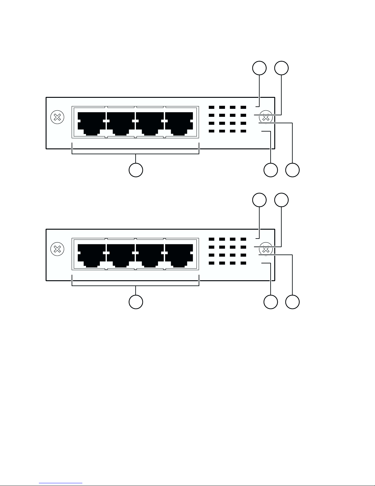
Figure 1 400-4T X and 8100-4TX MDA front panels
400-4TX MDA
8100-4TX MDA
1
100
10
F Dx
Activity
400-4TX MDA
1
100
10
F Dx
Activity
2
45 3
2
8100-4TX MDA
45 3
BS45042B
The 10BASE-T/100BASE -TX MDA port s can operate at ei t her
10 Mb/s or 100 Mb/s. The port speed is determined through
autonegotiation with its connecting device.
6

Table 2 describe s th e 400-4TX and 8100-4TX MDA front-panel.
Table 2 400-4TX and 8100-4TX MDA fron t panel
Item Label D escription
1 100 100BA SE-TX port status LEDs (green):
On: The corresponding port is set to operate at
100 Mb/s.
Off: The link connection is bad or there is no
connection to this port.
Blinking: The corresponding port is management
disabled.
2 1 0 10BASE-T port status LEDs (green):
On: The corresponding port is set to operate at
10 Mb/s.
Off: The link connection is bad or there is no
connection to this port.
Blinking: The corresponding port is management
disabled.
3 F Dx Full-duplex port status LEDs (green):
On: The co rresp onding port is i n fu ll-du plex m ode.
Off: The corresponding port is in half-duplex
mode.
4 Activity Port activity LEDs (green):
Blinking: Indicates the network activity level for the
corresponding port. A high level of network activity
can cause LEDs to appear to be on continuously.
5 10BASE-T/100 BASE-TX RJ-45 (8-pin modular) port
connectors.
7
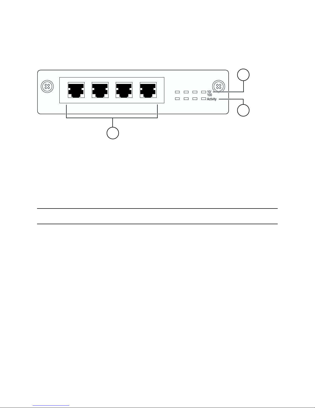
Figure 2 shows the front panel of the BPS2 000-4TX MDA.
Figure 2 BPS2000-4TX MDA front panel
1
BPS2000-4TX MDA
3
9792EA
Table 3 de scribe s the BPS2000-4TX MDA front-panel
components.
Table 3 BPS2000- 4TX M DA description
Item Label Description
1 10/100 10BASE-T/100BASE-TX port status LEDs:
On (green): The corresponding port is set to
operate at 100 Mb/s.
2
2 Activity Port activity LEDs (green):
On (yellow): The corresponding port is set to
operate at 10 Mb/s.
Off: The link connection is bad or there is no
connection to this port.
Blinking (green): Indicates the network activity
level for the corresponding port. A high level of
network activity can cause LEDs to appear to be
on continuously.
8
 Loading...