

Page 1

Installing Media
Dependent Adapters
(MDA)s
Part No. 302403-A Rev 00
June 1998
Page 2

© 1998 by Bay Networks, Inc.
All rights reserved.
Trademarks
Bay Networks is a registered trademark and BayStack is a trademark of Bay
Networks, Inc. All other trademarks and registered trademarks are property of their
respective owners.
Statement of Conditio ns
In the interest of improving internal design, operational function, and/or re liability,
Bay Networks, Inc. reserves the right to make changes to the products described in
this document without notice.
Bay Networks, Inc. does not assume any liability that may occur due to the use or
application of the product(s) or circuit layout(s) described herein.
Federal Communications Commission (FCC) Compliance Notice:
Radio Frequency Notice
Note: This equipment has been tested and found to comply with the limits for a
Class A digital device, pursuant to Part 15 of the FCC rules. These limits are
designed to provide reasonable protection against harmful interference when the
equipment is operated in a commercial environment. This equipment generates,
uses, and can radiate radio frequency energy. If it is not installed and used in
accordance with the instruction manual, it may cause harmful interference to radio
communications. Operation of this equipment in a residential area is likely to cause
harmful interference, in which case users will be required to take whatever
measures may be necessary to correct the interference at their own expense.
EN 55 022 Declaration of Conformance
This is to certify that the Bay Networks 100BASE-FX/TX MDA are shielded
against the generation of radio interference in accordance with the application of
Council Directive 89/336/EEC, Article 4a. Conformity is declared by the
application of EN 55 022 Class A (CISPR 22).
Warning: This device is a Class A product. In a domestic environment, this product
may cause radio interference, in which case, the user may be required to take
appropriate measures.
These products conform to the provisions of Council Directive 89/336/EEC and 72/
23/EEC. The Declaration of Conformity is available on the Bay Networks World
Wide Web site at www.baynetworks.com.
Page 3

Introduction
This document provides proced ures for i nst alli n g opt ion al
plug-in media dependent adapter (MDAs) into supported
Bay Networks products equipped with an expansion slot.
The MDAs can sup port high -speed connections to serv ers,
shared Fast Ethernet hubs, or backbone devices.
Installing or removing an MDA from an
Note:
operating switch (hot-swappin g) causes the switch to
auto-reset as soon as the insertion or removal of the
device is sensed by the switch software. Although the
switch is hot-swap survivable, data integrity during
the reset will be compromised.
The following MDA versions are available:
• 400-4TX MDA --- 10BASE-T/100BASE-TX MDA
(4-port copper)
• 400-2FX MDA ---100BASE-FX MDA (2-port fiber)
• 450-1SR MDA --- 1000BASE-SX MDA (1-port
shortwave gigabit fiber, with 1-redundant port)
• 450-1SX MDA --- 1000BASE-SX MDA (1-port
shortwave gigabit fiber)
• 450-1LR MDA --- 1000BASE-LX MDA (1-port
longwave gigabit fiber, with 1-redundant port)
• 450-1LX MDA --- 1000BASE-LX MDA (1-port
longwave gigabit fiber)
1
Page 4

Bay Networks is constantly adding new models and
features to existin g product lines; see your Bay Networks
sales representative for a full range of available MDAs.
For more information about BayStack 450 switches, refer
to
Using the BayStack 450 Switch
.
The MDAs are described in the following sections.
The following Bay Networks products are supported:
• BayStack 450 switches
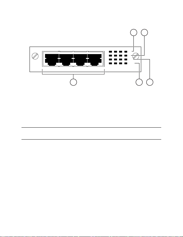
400-4TX MDA
The 400-4TX MDA (Figure 1
) uses a standard RJ-45
connector to attach an Ethernet device. This MDA is
capable of operating at either 10 Mb/s or 100 Mb/s speed.
The speed is determined through autonegotiation with its
connecting device.
Table 1
describes the 400-4TX MDA components and
LEDs.
2
Page 5
21
100
10
F Dx
Activity
400-4TX MDA
5
Figure 1. 400-4TX MDA Front-Panel
Table 1. 400-4TX MDA Components
Item Label Description
1
100 100BASE-TX port status LEDs (green):
On: The corresponding port is set to
operate at 100 Mb/s.
Off: The link connection is bad or
there is no connection to this port.
Blinking: The corresponding port is
management disabled.
3
34
8540EA
(continued)
Page 6

Table 1. 400-4TX MDA Components
(continued)
Item Label Description
2 10 10BASE-T port status LEDs (green):
On: The corresponding port is set to
operate at 10 Mb/s.
Off: The link connection is bad or
there is no connection to this port.
Blinking: The corresponding port is
management disabled.
3 F Dx Full-duplex port status LEDs (green):
On: The corresponding port is in
full-duplex mode.
Off: The corresponding port is in
half-duplex mode.
4 Activity Port activity LEDs (green):
Blinking: Indicates the network
activity level for the corresponding
port. A high level of network activity
can cause LEDs to appear to be on
continuously
5 10BASE-T/100BASE-TX RJ-45 (8-pin
modular) port connectors.
4
Page 7

400-2FX MDA
The 400-2FX MDA (Figure 2
) is used to attach a
fiber-based 100 Mb/s connection to the other compatible
Fast Ethernet devices. This MDA accepts standard SC
connections using 62.5/125 µm fiber optic cable. The
400-2FX MDA is not supported on single-mode fiber
cabling.
The 400-2FX MDA can be used as a direct attachment to
end stations, servers, switches, or repeaters where
multimode fiber optic cabling is already installed.
21
4
100BASE-FX
Link
F Dx
RXTX
Activity
400-2FX MDA
3
8541EA
100BASE-FX
RXTX
Figure 2. 400-2FX MDA Front-Panel
Table 2 describes the 400-2FX MDA components and
LEDs.
5
Page 8

Table 2. 400-2FX MDA Components
Item Label Description
1 Link Communications link LEDs (green):
On: Valid communications link
established.
Off: The communications link
connection is bad or there is no
connection to this port.
Blinking: The corresponding port is
management disabled.
2 F Dx Full-duplex port status LEDs (green):
On: The corresponding port is in
full-duplex mode.
Off: The corresponding port is in
half-duplex mode.
(continued)
6
Page 9

Table 2. 400-2FX MDA Components
Item Label Description
3 Activity Port activity LEDs (green):
Blinking: Indicates the network
activity level for the corresponding
port. A high level of network activity
can cause LEDs to appear to be on
continuously.
4
100BASE-FX SC port connectors.
(continued)
1000BASE-SX MDAs
There are two versions of the 1000BASE-SX (shortwave
gigabit) MDAs:
• The 450-1SR MDA is a single MAC MDA with a
separate redundant Phy (backup Ph y port).
• The 450-1SX MDA is a single Phy MDA.
Both versions (Figure 3
) use shortwave 85 0 nm f iber op tic
connectors to connect devices o ver m ultimode (550 meter)
fiber optic cable.
7
Page 10

450-1SR MDA
21
(1-port redundant)
4
1000BASE-SX
TXRX
Link
Phy Select
RX
Activity
450-1SR MDA
3
21
1000BASE-SX
TX
450-1SX MDA
(single port)
1000BASE-SX
TX RX
4
Link
Phy
Activity
450-1SX MDA
3
8542EA
Figure 3. 1000BASE-SX MDA Front-Panel
Table 3 describes the 1000BASE-SX components and
LEDs.
8
Page 11

Table 3. 1000BASE-SX MDA Components
Item Label Description
1 Link Communication link LEDs (green):
On: Valid communications link.
Off: The communications link
connection is bad or there is no
connection to this por t.
Blinking: The corresponding port
is management disabled.
2 Phy Select Phy Selection LEDs(green):
On: The correspond ing Ph y port is
selected.
Off: The correspond ing Ph y port is
in backup mode.
3 Activity Port activity LEDs (green):
Blinking: Indicates netw ork activity
level for the correspondin g po rt. A
high level of network activity can
cause LEDs to appear to be on
continuously.
4 1000BASE-FX SC port connectors.
9
Page 12

1000BASE-LX MDA
There are two versions of the 1000BASE-LX (longwave
gigabit) MDAs:
• The 450-1LR MDA is a single MAC MDA with a
separate redundant Phy (backup Ph y port).
• The 450-1LX MDA is a single Phy MDA.
Both versions (Figure 4
) use longwa ve 1300 nm fi ber optic
connectors to connect devices over singlemode (3
kilometer) or multimode (550 meters) fiber optic cable.
Table 4
describes the 1000BASE-LX MDA components
and LEDs.
10
Page 13

450-1LR MDA
(1-port redundant)
1000BASE-LX
TX
1000BASE-LX
TXRX
Link
Phy Select
RX
Activity
450-1LR MDA
4
450-1LX MDA
(single port)
1000BASE-LX
TX RX
Link
Phy
Activity
450-1LX MDA
4
8565EA
Figure 4. 1000BASE-LX MDA Front-Panel
21
3
21
3
11
Page 14

Table 4. 1000BASE-LX MDA Components
Item Label Description
1 Link Communication link LEDs (green):
On: Valid communications link.
Off: The communications link
connection is bad or there is no
connection to this por t.
Blinking: The corresponding port
is management disabled.
2 Phy Select Phy Selection LEDs(green):
On: The correspond ing Ph y port is
selected.
Off: The correspond ing Ph y port is
in backup mode.
3 Activity Port activity LEDs (green):
Blinking: Indicates netw ork activity
level for the correspondin g po rt. A
high level of network activity can
cause LEDs to appear to be on
continuously.
4 1000BASE-FX SC port connectors.
12
Page 15

Installing an MDA
The Uplink Module slot on the BayStack 450 switches
accommodates a single MDA. The connection can be
either an RJ-45 10/100BASE-TX MDA or a fiber
(100BASE-FX or 1000BASE-SX/LX) MDA with an SC
or PHY connector.
Installing or removing an MDA from an
Note:
operating switch (hot-swappin g) causes the switch to
auto-reset as soon as the insertion or removal of the
device is sensed by the switch software. Although the
switch is hot-swap survivable, data integrity during
the reset will be compromised.
To install an MDA into the Uplink Module slot, follow
these steps:
1. Unplug the AC power cord from the back of the
switch.
2. Loosen the thumbscrews and remove the filler
panel (or previously installed MDA) from the
Uplink Module slot.
13
Page 16

3. Insert the MDA into the chassis slot (see Figure 5)
taking care to slide the MDA onto the guides
provided on the chassis.
Caution:
provided. Failure to align the guid es coul d resu lt in
bent and broken pins
Figure 5. Installing an MDA
Make sure the MDA slides in on the guide s
8531FA
4. Press the MD A firmly into the chassis slot. Be sure
that the MDA is fully seated into the mating
connector.
5. Secure the MDA in the chassis by tightening the
thumb screws on the MDA front panel.
6. Attach devices to the MDA ports (refer to the
Using the BayStack 450 Switch.
14
Page 17

After connecting the port cables, continue to follow the
instructions in that manual to connect power and v erify the
installation
.
The IEEE 802.3u specification requires that all
Note:
ports operating at 100 Mb/s use only Category 5
unshielded twisted pair (UTP) cabling.
15
 Loading...