

Page 1

296-1011-202
Document Revision 02.01
CVX Multi-Service Access Switch
Release 5.0
August 2001
CVX 600 Multi-Service
Access Switch
Hardware Installation Guide
Page 2

*Nortel, Nortel Networks, the Nortel Networks corporate logo, the Globemark design, and CVX are trademarks of Nortel
Networks. All other trademarks are the property of their owners.
© 2001 Nortel Networks. All rights reserved. Information in this document is subject to change without notice. Nortel
Networks assumes no responsibility for any errors that may appear in this document.
Printed in the USA
Page 3
Regulatory and Safety
Regulator y Inf or m ation
U.S.A. Requirements
FCC Radio Frequency Notice for the CVX 600 Access Switch
This device complies with Part 15 of the FCC Rules. Operation is subject to the following two conditions:
• This device may not cause harmful interfere nce.
• This device must accept any interference received, including interference that may cause undesi r ed
operation.
Note: This equipment has been tested and found to comply with the limits for a Class A digital device, pursuant to
Part 15 of the FCC Rules. These limit s are desig ned to prov ide reaso nable pro tection against harmfu l inter ference in a
residential installation. This equipment generates, uses and can radiate radio frequency energy and, if not installed and
used in accordance with the instructions, may cause harmful interference to radio communi cat ions. However, there is
no guarantee that interference will not occur in a particular installation. If this equipment does cause harmful
interference to radio or te le visio n rece pt ion , wh ic h ca n be d etermin e d by turn in g the equipment off a n d o n, th e use r is
encouraged to try to correct th e in terference by one or more of the following measures:
• Reorient or relocate the receivin g antenna.
• Increase the separation between the equipment and receiver.
• Connect the equipment into an outlet on a circuit different from that to which the receiver is connected.
• Consult the dealer or an experi enced radio/TV technician for help.
FCC Part 68 General Information
This equipment complies with Part 68 of the FCC rules. This equipment uses the following USOC RJ-48 jacks:
Interface Service Code Facility Code
1.544 Mb/s superframe format (SF) without
line power
1.544 Mb/s superframe format (SF) and
B8ZS without line power
1.544 Mb/s ANSI extended superframe
format (ESF) without line power
1.544 Mb/s ANSI extended superframe
format (ESF) and B8ZS without line power
296-1011-202 Rel. 5.0, Doc. Rev. 02.01 iii
6.0N 04DU9-BN
6.0N 04DU9-DN
6.0N 04DU9-1KN
6.0N 04DU9-1SN
Page 4

CVX 600 Hardware Installation Guide
Regulatory Information
If you experience trouble with this equipment, please contact Nortel Networks for repair and warranty information. If
there is a problem with the network, the telephone company may request that you remove the equipment from the
network until the problem is resolved.
Nortel Networks recommends that you insta ll a n AC surg e prote c to r in the AC outlet to which the eq ui pm e nt is
connected. This helps to prevent damage to the equipment caused by local light ning strikes or other electrical surge s.
FCC and Telephone Company Procedures and Requirements
In order to connect t his eq uipmen t to the netwo rk, yo u must p rovid e the lo cal te lephon e com pany wit h the re gist ration
number of this equipment, and you mus t or d e r the pr o pe r connections.
To order the proper service, provide the telephon e compan y with the followin g info rm ation :
• Number of required jacks and their USOC numbers
• Sequence in which the trunks are to be connected
• Facility interface codes, by position
UL Listing and CSA Certification - U.S. and Canada
This equipment has been Listed by Underwriter Laboratories, Inc. and certified by CSA for use in the U.S. and
Canada to the requirements of UL 1950. Third Edition - Safety of Information Technology Equipment. Including
Electrical Business equipment and Canad ian Standards Association CAN/C SA C22.2 No. 950-95 Third Edition.
Australian Requirements
N441
The regulator for telecommunications and radio communications in Australia is the ACA (Australian
Communications Authority). This equipment is labeled with the A-Tick mark, which indicates that the product
complies with both EMC and Telecommunications requirements and establishes a traceable link between the
equipment and the manufacturer. It is also an indication to the user that the product can be connected to a
telecommunications network.
Canadian Requirements
Canadian Department of Communications Radio Interference Regulations
This digital apparatus (CVX 600) does not exceed the Class A limits for radio-noise emissio ns from digita l apparatus,
as documented in the Radio Interference Regulations of the Canadian Department of Communications.
Règlement sur le brouillage radioélectrique du ministère des Communications
Cet appareil numérique (CVX 600) respe cte les limites de bruits radioélectriques visant les appareil s numériques de
classe A prescrites dans le Règlement sur le brouillage radioél ec tr ique du minist ère des Communications du Canada.
Canada CS-03 Rules and Regulations
Note: The Canadian Department of Com munication s label iden tifies certifie d equip ment. The certifi cation means tha t
the equipment meets cert ain telecommunicatio ns network protective, o perat ional, and safety requir ements. The
Department does not guarantee the equipment will operate to the user’s satisfaction.
iv 296-1011-202 Rel. 5.0 , Doc. Rev. 02.01
Page 5

Regulatory and Safety
Regulatory Information
Before installing this equipment, ensure that it is permissible to connect to the facilities of the local
telecommunications company. You must install this equipment using an acceptable connection method.
Repairs to certified equipment should be made by a supplier-designated representative. If yo u make repairs or
alterations to this equipment, or if the equipment malfunctions, the telecommunications company may request that
you disconnect the equipment.
You shou ld en s ure , f or yo ur ow n pro te c tio n, tha t the ele ct ri ca l grou nd co nn ec tio n s for the pow e r utility , telephone
lines, and internal water-pipe system, if present, are connected. This precaution may be particularly important in rural
areas.
Caution: You should not attempt to make such connection s . You should contact the appropriate insp ection authority
or electrician.
Canada CS-03 Règles et règlements
Note: L’étiquette du ministère des Communications du Canada indique que l’appareillage est certifié, c’est-à-dire
qu’il respecte certaines exigen ces de sécurité et de fonctionnement visant le s réseaux de télécommunications. Le
ministère ne garantit pas que l’appareillage fonctionnera à la satisfaction de l’utilisateur.
Avant d’installer l’appareillage, s’assurer qu’il peut être branché aux installations du service de télécommunications
local. L’appa reilla g e doit aussi être raccordé selon des méthodes acceptées.
Les réparations de l’appareillage certifié devraient être con f iées à un service désigné par le fournisseur. En cas de
réparation ou de modification effectuées par l’utilisateur ou de mauvais fonctionnement de l’appareillage, le service
de télécommunicatio ns peut demander le débranchement de l’appareillage.
Pour leur propre sécurité, les utilisateurs devraient s’assurer que les mises à la terre des l ignes de distribution
d’électricité, des lignes téléphoniques et de la tuyauterie métallique interne sont raccordées ensemble. Cette mesure d e
sécurité est particulièrement importante en milieu rural.
Attention: Les utilisateurs ne doivent pas pr océder à ces ra cc o r de m e nts, m a is doivent plutôt faire appel aux pouvoirs
de réglementation en cau se ou à un électricien, selon le cas.
European Requirements
EMI/EN 55 022 Statement
This certifies that the Nortel Networks CVX 600 switch is shielded against the generation of radio interference in
accordance with the application of Council Directive 89/336/EEC. Conformity is declared by the application of EN 55
022:1998 and EN 55 024:1998.
Warning: This is a Class A product. In a residential area, this product m ay cause radio interfe rence , in which case th e
user may be required to take the app ropriate measures.
EC Declaration of Conformity
This product conforms to the provisions of Council Directive’s EMC Directive (89/336/EEC), Low Voltage Directive
(73/23/EEC), and R+TTE Directive (1999/5/EC).
296-1011-202 Rel. 5.0, Doc. Rev. 02.01 v
Page 6
CVX 600 Hardware Installation Guide
Regulatory Information
Japan/Nippon Requirements Only
Voluntary Control Council for Interference (VCCI) Statement
Voluntary Control Council for Interference (VCCI) Statement
This equipment is in the 1st category (information equipment to be used in commercial and/or industrial areas) and
conforms to the standards set by the Voluntary Control Council for Interference by Data Processing Equipment and
Electronic Office Machines that are aimed at preventing radio interference in commercial and/or industrial areas.
Consequently, when this equipment is used in a resident ial area or in an adjacent area thereto, radio interference may
be caused to equipment such as radios and TV receivers.
JATE Requirements
This certifies that the Nortel Networks CVX 600 conforms to the standards set by JATE (Japan Approvals Institute for
Telecommunications Equipment) as of 06/06/01 with Approval Numbers CD01-0459JP and L01-0145.
vi 296-1011-202 Rel. 5.0 , Doc. Rev. 02.01
Page 7

Regulatory and Safety
Safety Warnings
Safety Warnings
General Warnings
The following safety warnings apply:
• Mechanical hazards and electrical shock hazards are possible if you remove one or more of the modules. There are
no operator-serviceable modules. Only qualified pe rsonnel should ser vice this equipment.
• This equipment must be connected to a protective ground according to the instructions in this manual. Improper
grounding may result in electrical shock.
• This equipment does not provide safety isolati on between any port that is connected to a digital network
termination point or any port to which terminal equipment is connected.
• The wall circuit breaker provides the main protection for this equipment. For -48 VDC operation, the equipment
must reside on its own circuit with a breaker rated for 20 A.
• Ensure that rack ins tallation does no t result in airflow bl ockage to power supply vents or chassis vents.
• Before installing the CVX 600 switch, en sure that the rack is sturdy and well-secured.
DC Power Supply Warnings
The DC power supply must be installed in a rest ric ted area, such as an equipment closet or room, in compliance with
Articles 110-16, 110-17, and 110-18 of the National Electric Code, ANSI/NFPA 70. The DC power source must be
isolated from the AC power source and must have a proper ground.
The grounded conductor of the DC supply circuit can be connected to the frame grounding conductor of the CVX 600
switch. In this case, the following conditions apply:
• The CVX 600 switch must be connected to the DC power supply grounded conductor or bondi ng jumper from the
grounding terminal bar or bus to which the DC power supply grounded conductor is connected.
• The CVX 600 switch must be located in the same area a s other equipment havi ng a connection bet w een the
grounded con duct or of the sam e DC supp ly cir cuit a nd the gr ound ing co nduc tor, and also the point of groundi ng of
the DC system. The DC system must not be grounded elsewhere.
• You must not switch or disconnect devices in the grounded conductor between t he DC power supply and the point
of connection of the grounding electrode conductor.
• A readily accessible disconnect device may be provided in the fixed wiring for a DC power supply. The device must
be rated for the voltage and current specified.
• Before installing equipment in a rack, consider the overall loading of the branch circuit.
For safety purposes, the DC power supply requires connection to a grounded outlet. To prevent possible injury from
voltages on the telecommunications network, disconnect all telecommunications netw ork lines before disconnecting
the DC power supply from the grounded outlet.
296-1011-202 Rel. 5.0, Doc. Rev. 02.01 vii
Page 8

CVX 600 Hardware Installation Guide
Safety Warnings
Lithium Battery Caution
Caution: Danger of explosion if battery is incorrectly replaced. Replace only with the same or equivalent type
recommended by the manufacturer. Discard used batteries according to the manufacturer’s instructions.
Attention: Il y a danger d’explosion s’il y a remplacement incorrect de la batterie. Rempla cer uniquement avec une
batterie du même type ou d’un type recommandé par le constructeur. Mettre au rebut les batteries usagées
conformément aux instructions du fabricant.
viii 296-1011-202 Rel. 5.0, Doc. Rev. 02.01
Page 9

Contents
Regulatory and Safety
Regulatory Information ......................... .............................................................................iii
U.S.A. Requirements ........ ....... ...... .............................................................................iii
Australian Requirements ............................................................................................ iv
Canadian Requirements ............................................................................................ iv
European Requirements .............................................................................................v
Japan/Nippon Requirements Only ............................................................................. vi
Safety Warnings ...............................................................................................................vii
General Warnings ......................................................................................................vii
DC Power Supply Warnings .......................................................................................vii
Lithium Battery Caution .............................................................................................viii
Preface
About This Guide......... ..................................................................................................... xv
Introduction ............................................................................................................... xv
Topics ............. ................................................................. .......................................... xv
Chapters and Appendixes in This Guide .........................................................................xvi
Information About CVX Products ....................................................................................xvii
About This Release .................. ...... ....... ...... ....... ...... ....... ................................ ...... ...xvii
Accessing Related Documentation ..........................................................................xvii
Accessing Software Upgrades .................................................................................xvii
Customer Services ........................................................................................................xviii
Technical Support ....................................................................................................xviii
Product Damage .....................................................................................................xviii
Equipment Problems ...............................................................................................xviii
Contents
296-1011-202 Rel. 5.0, Doc. Rev. 02.01 ix
Page 10

Contents
Chapter 1
Chassis Installation
About This Chapter ...... ....... ...... ....... ...... ....... ...... ....... ......................................................1-1
Introduction ..............................................................................................................1-1
Topics ............. ................................................................. ......................................... 1-1
CVX 600 Chassis Overview ...........................................................................................1-2
Description ...............................................................................................................1-2
Remote Access Configuration ..................................................................................1-2
Where to Install ........................................................................................................1-2
Front View of CVX 600 Chassis ...............................................................................1-3
Rear View of CVX 600 Chassis ...............................................................................1-4
Preparing the Site for the Installation ..............................................................................1-5
Overview .................................................................................................................. 1-5
Reference .................................................................................... .............................1-5
Mounting Options ..................... ...... ....... ................................................................ ...1-5
Mounting the CVX 600 in a Rack ...................................................................................1-7
Rack Capacity ..........................................................................................................1-7
Rack Requirements ..................................................................................................1-7
Nortel Networks Rack Recommendation .................................................................1-7
Rack Placement .......................................................................................................1-7
Ceiling Requirements ...............................................................................................1-8
Size and Weight Considerations ..............................................................................1-8
Reference .................................................................................... .............................1-8
Nortel Networks PTE 2000 Rack .............................................................................1-8
Access Considerations ...........................................................................................1-11
Rack Cooling Requirements ..................................................................................1-11
AC and DC Power ........................................................................................................1-12
Description .............................................................................................................1-12
Preparing for the CVX 600 Installation .........................................................................1-14
Overview ................................................................................................................ 1-14
Unpacking the Shipment ........................................................................................1-14
Checking the Shipment ..........................................................................................1-15
Tools and Equipment Needed ................................................................................1-16
x 296-1011-202 Rel. 5.0 , Doc. Rev. 02.01
Page 11

Installing the CVX 600 Chassis ....................................................................................1-18
Mounting Options ..................... ...... ....... .................................................................1-1 8
Positioning the Chassis on a Flat Surface .............................................................1-18
Installing the Feet on the Bottom of the Chassis ....................................................1-19
Mounting the Chassis in a Rack .............................................................................1-20
Telco and EIA Rack Hole Spacing .........................................................................1-21
Hardware Needed to Complete the Chassis Installation ........................................1-22
Installing the Chassis .............................................................................................1-23
Chapter 2
Chassis Connections
About This Chapter ...... ....... ...... ....... ...... ....... ...... ....... ......................................................2-1
Introduction ..............................................................................................................2-1
Topics ............. ................................................................. ......................................... 2-1
Connecting Alarms .........................................................................................................2-2
Introduction ..............................................................................................................2-2
Alarm Categories .....................................................................................................2-2
Alarm Types .............................................................................................................2-3
Reference .................................................................................... .............................2-5
Procedure ............. ....... ...... ....... ...... ..........................................................................2-6
Connecting Network Cables ...........................................................................................2-7
Overview .................................................................................................................. 2-7
Reference .................................................................................... .............................2-7
Connecting to 10/100BASE-T Interfaces .................................................................2-8
Connecting to DS1/T1 Interfaces .............................................................................2-9
Connecting to E1 Interfaces ...................................................................................2-10
Connecting to DS3 Interfaces ................................................................................2-11
Connecting to the HSSI Interface ...........................................................................2-12
Connecting to the OC3/STM1 Interface .................................................................2-13
Contents
296-1011-202 Rel. 5.0, Doc. Rev. 02.01 xi
Page 12

Contents
Connecting Power to the Chassis ................................................................................2-16
Before You Start .....................................................................................................2-16
Requirements .................... ....................................... ............................................. .2-16
Grounding the Chassis ..........................................................................................2-17
Connecting to a Customer-Supplied DC Power Source ........................................2-21
Next Step ...............................................................................................................2-24
Connecting Chassis to an AC Power Source .........................................................2-25
Routing the Cables .......................................................................................................2-27
Cable Mounts .........................................................................................................2-27
Suggested Use .......................................................................................................2-27
Locations of Cable Mounts .....................................................................................2-27
Routing Fiber Optic Cables ....................................................................................2-28
Installing and Removing the Flash Memory Cards .......................................................2-29
Description .............................................................................................................2-29
Reference .................................................................................... ...........................2-29
Inserting a Flash Memory Card ..............................................................................2-30
Removing a Flash Memory Card ...........................................................................2-31
Connecting Equipment to the Console Port .................................................................2-32
Introduction ............................................................................................................2-32
Connecting a Terminal ...........................................................................................2-33
Connecting a PC ....................................................................................................2-35
Connecting a Modem .............................................................................................2-37
Connecting a Terminal Server ................................................................................2-39
Connecting Equipment to a Local Ethernet Port ..........................................................2-41
Description .............................................................................................................2-41
Connecting a Remote Device Using an Ethernet Port ...........................................2-41
Applying Power to the CVX 600 ...................................................................................2-42
Procedure ............. ....... ...... ....... ...... ........................................................................2 -4 2
xii 296-1011-202 Rel. 5.0 , Doc. Rev. 02.01
Page 13

Checking the LEDs .......................................................................................................2-43
Introduction ............................................................................................................2-43
SCC-SM, SCC-RLTM (Ethernet 10/100 Mb/s ports) ..............................................2-44
SCC-HSSI-SM, SCC-HSSI-RLTM .........................................................................2-46
Optical SCC-II ........................................................................................................2-48
Optical DAC ...........................................................................................................2-51
DAC-SM LEDs .......................................................................................................2-52
MAC-SM LEDs .......................................................................................................2-54
Chapter 3
Replacing CVX 600 Components
About This Chapter ...... ....... ...... ....... ...... ....... ...... ....... ......................................................3-1
Introduction ..............................................................................................................3-1
Topics ............. ................................................................. ......................................... 3-1
Attaching the Antistatic Wrist Strap .................................................................................3-2
Location of Wrist Strap .............................................................................................3-2
Purpose of Wrist Strap .............................................................................................3-2
How to Attach the Wrist Strap ..................................................................................3-2
Replacing Modules and Filler Panels .............................................................................3-4
Introduction ..............................................................................................................3-4
Removing and Installing Filler Panels ......................................................................3-4
Replacing the SCC-SM ..........................................................................................3-11
Replacing the SCC-LTM/RLTM ..............................................................................3-16
Replacing Other Service Modules ..........................................................................3-21
Replacing the DAC-LTM/-RLTM .............................................................................3-26
Replacing the Fan Module ............................................................................................3-31
Description .............................................................................................................3-31
Removing the Fan Module .....................................................................................3-32
Installing a Fan Module ..........................................................................................3-34
Replacing a PDU Module .............................................................................................3-36
Description .............................................................................................................3-36
Removing the PDU Module ....................................................................................3-36
Installing a PDU Module .........................................................................................3-38
Contents
296-1011-202 Rel. 5.0, Doc. Rev. 02.01 xiii
Page 14

Contents
Replacing a Power Module ...........................................................................................3-40
Description .............................................................................................................3-40
Removing the Power Module .................................................................................3-40
Installing a Power Module ......................................................................................3-42
Ordering Replacement Components ............................................................................3-44
How to Order .. ...... ....... ...... ....... ...... ....... .................................................................3 -4 4
Appendix A
Technical Specifications
About This Appendix .................................... ...... ....... ...... ....... ...... ...... ....... ...... ............... A-1
Introduction ............................................................................................................. A-1
Topics ............. ................................................................. ........................................ A-1
Chassis Specifications and Clearances ........................................................................ A-2
Dimensions, Weight, Slot Capacity ......................................................................... A-2
Clearance ............. ....................................... ....................................... ..................... A-2
Environmental Specifications ........................................................................................ A-3
Specifications . ................................................................. ........................................ A-3
Cooling Requirements ................................................................................................... A-4
Need for Ventilation ................................................................................................. A-4
Methods of Cooling ................................................................................................. A-4
Airflow ..................................................................................................................... A-4
Electromagnetic Emissions and Radio Frequency ........................................................ A-5
CVX 600 Requirements .......................................................................................... A-5
Cable Specifications ...................................................................................................... A-6
Cables Supplied by Nortel Networks ....................................................................... A-6
Cables Supplied by the Customer ........................................................................... A-6
Management Console Cable Specifications ........................................................... A-7
HSSI Interface ......................................................................................................... A-9
Ethernet 10/100BASE-TX Interface Cable Specifications ......................................A-11
E1 and T1 Interface Line Specifications ................................................................ A-12
E1 and T1 Shielded Cable Specifications ............................................................. A-13
DS3 Coaxial Cable Specifications ......................................................................... A-13
Optical Cable Specifications ................................................................................. A-13
xiv 296-1011-202 Rel. 5.0, Doc. Rev. 02.01
Page 15

Tandem CVX to RAS CVX Crossover Cable ............................................................... A-14
Introduction ........................................................................................................... A-14
Tool and Parts Needed .......................................................................................... A-14
Pin Data ................................................................................................................ A-14
Audible and Visual Alarm Interface Specifications ...................................................... A-16
Alarm Interface Connector .................................................................................. A-16
Signals .................................................................................................................. A-16
Reference .................................................................................... .......................... A-16
Power Specifications ................................................................................................... A-17
Power Options ....................................................................................................... A-17
AC Power Requirements .......... ...... ....... ...... ....... ................................ ...... ....... ...... A-17
DC Power Requirements ...................................................................................... A-17
SCC-LTM/-RLTM Interfaces ........................................................................................ A-18
DAC-LTM/-RLTM External Clock Interface ................................................................. A-19
Contents
296-1011-202 Rel. 5.0, Doc. Rev. 02.01 xv
Page 16

Page 17

About This Guide
Introduction
This guide describe s how to ins tall the Nortel Netwo rks CVX* 600 Mult i-Ser vice
Access Switch for Telco and Internet service provider (ISP) customers. Because
installation p roc edur es vary between Telco and ISP customers , use this manual as
a guide for installation.
Preface
Topics
This preface covers the following topics:
Topic Page
Chapters and Appendix es in This Guide xvi
Information About CVX Products xvii
About This Release xvii
Accessing Related Documentation xvii
Accessing Software Upgrades xvii
Customer Services xviii
Technical Support xviii
Product Damage xviii
Equipment Problems xviii
296-1011-202 Rel. 5.0, Doc. Rev. 02.01 xv
Page 18

CVX 600 Hardware Installation Guide
Chapters and Appendixes in This Guide
Chapters and Appendixes in This Guide
This guide contains the following chapters and appendixes:
For Go to
Chassis Installation Chapter 1
Chassis Connections Chapter 2
Replacing CVX 600 Components Chapter 3
Technical Specifications Appendix A
xvi 296-1011-202 Rel. 5.0, Doc. Rev. 02.01
Page 19

Information About CVX Products
About This Release
This version of the CVX access switch documentation supports software
delivered to customers using CVX Release 5.0 software.
Accessing Related Documentation
For information about gaining access to documentation, contact your Nortel
Networks account representative.
Accessing Software Upgrades
Software upgrades are accessible online through the World Wide Web at http://
www.nortelnetworks.com. Click Customer Support > Software Distribution
and follow the inst r uct ion s t o download software upgr ade s f or your CVX product.
Preface
Information About CVX Products
Access to software upgrades is available to customers with Performance Pack
support agreements. Contact your Nortel Networks account representative for
more information about Performance Packs or gaining access to software
upgrades.
296-1011-202 Rel. 5.0, Doc. Rev. 02.01 xvii
Page 20

CVX 600 Hardware Installation Guide
Customer Services
Customer Services
Technical Support
In the USA and Canada: If you are within your warranty period or have
purchased a Performance Pack support agreement covering your CVX network,
dial 1-800-758-4827 to contact a Technical Support engineer. If you would like
information regarding Performance Packs, please contact your Nortel Networks
account representative.
Outside the USA: Contact your Regional Nortel Networks Support Prime.
Product Damage
If any part of the CVX 600 is damaged, contact the shipper to conduct an
inspection and prepare a damage report. Save the shipping container and all
packing materials until the inspection and the damage report are completed.
In addition, c ont act Technical Suppor t as instructed in t he previous section so that
arrangements can be made for replacement equipment. Do not return any part of
the shipment until you receive detailed instructions from a technical
representative.
Equipment Problems
If your equipment is not working properly, you should immediately remove it
from the telephone line to prevent any possible damage to the telephone network.
If the telephone company identifies a problem, they may notify you prior to
discontinuing telephone service. After notification, you will be given an
opportunity to corre ct the pr obl em. You will also be inf or med of your right to file
a complain t with the Federal Communicati ons Commission (FCC ).
If repair or modification is required in order for your equipment to operate
properly, contact Technical Support. All repairs or modifications must be
completed by Nortel Networks or an authorized Nortel Networks representative.
xviii 296-1011-202 Rel. 5.0 , Doc. Rev. 02.01
Page 21

About This Chap te r
Introduction
This chapter describes how to install the CVX 600 chassis.
Topics
Chapter 1
Chassis Installation
This chapter covers the following topics:
Topic Page
CVX 600 Chassis Overview 1-2
Preparing the Site for the Installation 1-5
Mounting the CVX600 in a Rack 1-7
AC and DC Power 1-12
Preparing for the CVX 600 Installatio n 1-14
Installing the CVX 600 Chassis 1-18
296-1011-202 Rel. 5.0, Doc. Rev. 02.01 1-1
Page 22

CVX 600 Hardware Installation Guide
CVX 600 Chassis Overview
CVX 600 Chassis Overview
Description
The CVX 600 chassis has 6 slots: 4 slot s a re res erved for the modem ac ces s ca rds
(MACs) and digital access cards (DACs), and 2 slots are reserved for the system
control cards (SCCs).
Remote Access Configuration
The CVX 600 chassis configured for remote access is equipped with the
following:
• An internal fan module for system cooling
• A redundant DC power interface
• An optional redundant AC power module
Where to Install
You can install the CVX 600 chassis on a flat surface, or you can install it in a
Telco or standard EIA 19-inch or 23-inch computer rack.
Note: A 23-inch computer rack requires optional mounting hardware,
which you can order from Nortel Networks.
1-2 296-1011-202 Rel. 5.0, Doc. Rev. 02.01
Page 23
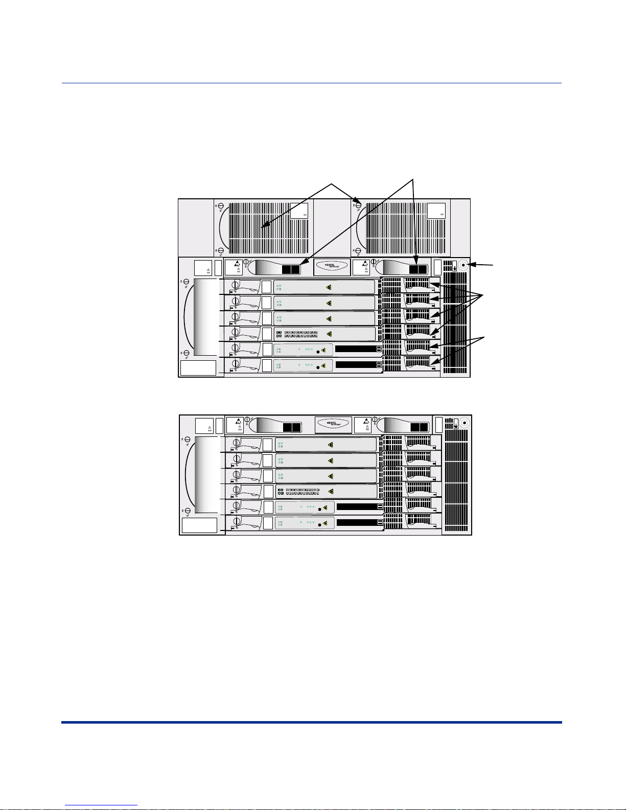
Front View of CVX 600 Chassis
The following figure shows the front of the CVX 600 chassis.
AC Chassis Option
Chassis Installation
CVX 600 Chassis Overview
AC Power
Modules
AC PM
AC PM 1 AC PM 2
PDUs (Circuit Breaker Modules)
AC PM
Fan
Module
Fans
BIP
PDU 1
1
2
3
4
SCC
SEC
SCC
PRI
DC Chassis Option
Fans
BIP
PDU 1
1
2
3
4
SCC
SEC
SCC
PRI
Modem/ISDN
Modem/ISDN
Modem/ISDN
DAC DS1x12
System
Pwr
System
Pwr
Modem/ISDN
Modem/ISDN
Modem/ISDN
DAC DS1x12
System
System
CVX-6oo
PCMCIA
PCMCIA
CVX-6oo
BIP
2
1
2
1
BIP
2
1
PCMCIA
2
1
PCMCIA
I
O
Good
Redun
Fail
Pwr
Good
Redun
Fail
Pwr
Good
Redun
Fail
Pwr
Good
Redun
RED
YEL
6
9
1
5
4
8
7
2
3
12
11
10
Fail
Pwr
Good
Redun
Fail
Good
Redun
Fail
Good
Redun
Fail
Pwr
Good
Redun
Fail
Pwr
Good
Redun
Fail
Pwr
Good
Redun
RED
YEL
Fail
Pwr
Good
Redun
Fail
Pwr
Good
Redun
Fail
Pwr
RESET
3
2
1
10/100 Enet
HSSI
RESET
3
2
1
10/100 Enet
HSSI
I
O
6
9
1
5
4
8
7
2
3
12
11
10
RESET
3
2
1
10/100 Enet
HSSI
RESET
3
2
1
10/100 Enet
HSSI
PDU 2
ESD
Jack
I
O
ESD Jack
Four slots for digital
access cards (DACs)
and modem access
cards (MACs)
Two slots
for primary
and redundant
system control
cards (SCCs)
PDU 2
ESD
Jack
I
O
CVX-0218B
296-1011-202 Rel. 5.0, Doc. Rev. 02.01 1-3
Page 24
CVX 600 Hardware Installation Guide
CVX 600 Chassis Overview
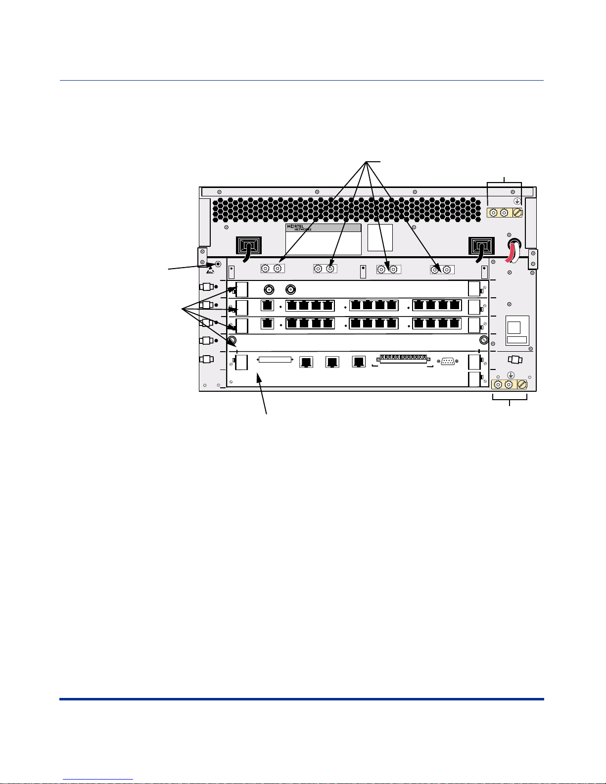
Rear View of CVX 600 Chassis
The following figure shows the rear of the CVX 600 chassis.
AC chassis option shown
DC power connections
(behind protective cover)
Grounding
lugs/screw
ESD
jack
our slots
or line
ermination
odules
System
Controller
AC PM 2
PDU 2 DC INPUT B
Rx
1
2
3
4
5
only
6
Clock
Clock
Tx
10
11
12
12
HSSI
9
10
11
9
2
3
10/100 Enet
Link
Link
RX
RX
10/100 Enet
7
8
7
8
1
Alarms
10/100 Enet
Link
RX
PDU 1 DC INPUT A
6
5
6
5
Visual
Ret
Min
Ret
Maj
Ret
Crit
Ret
Min
Ret
2
4
3
2
4
3
Console
Audible
Maj
Ret
Crit
System control card termination module
AC PM 1
DS3
1
E 1 x 12
1
1
OC3/STM1
DS1 x 12
System
2
Main Chassis
3
4
5
6
Grounding
lugs/screw
CVX-0219B
1-4 296-1011-202 Rel. 5.0, Doc. Rev. 02.01
Page 25

Preparing the Site for the Installation
Preparing the Site for the Installa tion
Overview
Before you install the CVX 600 chassis, you need to prepare your site. Consider
the method of mou nting (rack or f lat s urfac e), t he in stal lation of the r ack ( if us ed),
tools and equipment needed, space requirements, and weight. These issues are
addressed in detail in this chapter.
Reference
For information about the environmental requirements and power specifications,
see Appendix A, “Technical Specifications.”
Chassis Installation
Mounting Options
You can mount the CVX 600 in one of two ways:
• Position the CVX 600 on a flat, sturdy, horizontal surface. See “Positioning
the Chassis on a Flat Surface” on page 1-18.
• Mount the CVX 600 in a rack.
296-1011-202 Rel. 5.0, Doc. Rev. 02.01 1-5
Page 26
CVX 600 Hardware Installation Guide
Preparing the Site for the Installation
AC PM
AC PM 1 AC PM 2
BIP
BIP
Fans
PDU 1
I
O
CVX-6oo
Filler
1
Redun
Failed
ISDN
Good
Power
2
dun
Re
Failed
Modem
Good
Power
3
Redun
Failed
Yellow Red
od
4
3
2
1
7
5
6
9
8
o
11
12
10
G
Power
DS1
4
led
Redun
Fai
2
2
HSSI
Reset
1
Ethernet
PCMCIA
1
3
1
ood
System
G
Power
5
Redun
Failed
2
2
HSSI
Reset
1
Ethernet
PCMCIA
1
3
1
System
Good
Power
6
BIP
Fans
PDU 1
I
O
CVX-6oo
Filler
1
Redun
Failed
ISDN
Good
Power
2
dun
Re
Failed
Modem
Good
Power
3
Redun
Failed
Yellow Red
4
3
2
1
7
5
6
9
8
11
12
10
Good
Power
DS1
4
d
le
Redun
Fai
2
2
HSSI
Reset
1
Ethernet
PCMCIA
1
3
1
ood
System
G
Power
5
Redun
Failed
2
2
HSSI
Reset
1
Ethernet
PCMCIA
1
3
1
System
Good
Power
6
BIP
Fans
PDU 1
I
O
CVX-6oo
Filler
1
Redun
Failed
ISDN
Good
Power
2
dun
Re
Failed
Modem
Good
Power
3
Redun
Failed
Yellow Red
r
4
3
2
1
7
5
6
9
8
11
12
10
Good
Powe
DS1
4
d
le
Redun
Fai
2
2
HSSI
Reset
1
Ethernet
PCMCIA
1
3
1
ood
System
G
Power
5
Redun
Failed
2
2
HSSI
Reset
1
Ethernet
PCMCIA
1
3
1
System
Good
Power
6
BIP
Fans
PDU 1
I
O
CVX-6oo
Filler
1
n
Redu
Failed
ISDN
Good
Power
2
d
Redun
Faile
Modem
Good
Power
3
Redun
Failed
Yellow Red
4
3
2
1
7
5
6
9
8
11
12
10
Good
Power
DS1
4
Redun
Failed
2
2
HSSI
Reset
1
Ethernet
PCMCIA
1
3
1
System
Good
Power
5
Redun
Failed
2
2
HSSI
Reset
1
Ethernet
PCMCIA
1
3
1
System
Good
Power
6
BIP
Fans
PDU 1
I
O
CVX-6oo
Filler
1
ailed
Redun
F
ood
ISDN
G
Power
2
Redun
Failed
er
ood
Modem
G
Pow
3
Redun
Failed
Yellow Red
4
3
2
1
7
5
6
9
8
11
12
10
Good
Power
DS1
4
Redun
Failed
2
2
HSSI
Reset
1
Ethernet
PCMCIA
1
3
1
ood
System
G
Power
5
Redun
Failed
2
2
HSSI
Reset
1
Ethernet
PCMCIA
1
3
1
System
Good
Power
6
BIP
Fans
PDU 1
I
O
CVX-6oo
Filler
1
n
ailed
Redu
F
ood
ISDN
G
Power
2
Redun
Failed
Modem
Good
Power
3
Redun
Failed
Yellow Red
4
3
2
1
7
5
6
9
8
11
12
10
Good
Power
DS1
4
d
le
Redun
Fai
2
2
HSSI
Reset
1
Ethernet
PCMCIA
r
e
1
3
1
ood
System
G
Pow
5
Redun
Failed
2
2
HSSI
Reset
1
Ethernet
PCMCIA
1
3
1
System
Good
Power
6
BIP
Fans
PDU 1
I
O
CVX-6oo
Filler
1
n
Redu
Failed
ISDN
Good
Power
2
Redun
Failed
er
Modem
Good
Pow
3
Redun
Failed
Yellow Red
r
4
3
2
7
5
1
6
9
8
11
12
10
Good
Powe
DS1
4
Redun
Failed
2
2
HSSI
Reset
1
Ethernet
PCMCIA
1
3
1
System
Good
Power
5
Redun
Failed
2
2
HSSI
Reset
1
Ethernet
PCMCIA
1
3
1
System
Good
Power
6
BIP
Fans
PDU 1
I
O
CVX-6oo
Filler
1
Redun
Failed
ISDN
Good
Power
2
dun
Re
Failed
Modem
Good
Power
3
Redun
Failed
Yellow Red
4
3
2
7
5
1
6
9
8
11
12
10
Good
Power
DS1
4
d
le
Redun
Fai
2
2
HSSI
Reset
1
Ethernet
PCMCIA
od
1
3
1
o
System
G
Power
5
Redun
Failed
2
2
HSSI
Reset
1
Ethernet
PCMCIA
1
3
1
System
Good
Power
6
BIP
Fans
PDU 1
I
O
CVX-6oo
Filler
1
Redun
Failed
ISDN
Good
Power
2
d
dun
Re
Faile
Modem
Good
Power
3
Redun
Failed
Yellow Red
4
3
2
7
5
1
6
9
8
ower
11
12
10
Good
P
DS1
4
d
le
Redun
Fai
2
2
HSSI
Reset
1
Ethernet
PCMCIA
1
3
1
ood
System
G
Power
5
Redun
Failed
2
2
HSSI
Reset
1
Ethernet
PCMCIA
1
3
1
System
Good
Power
6
BIP
Fans
PDU 1
I
O
CVX-6oo
Filler
1
Redun
Failed
ISDN
Good
Power
2
dun
Re
Failed
Modem
Good
Power
3
Redun
Failed
Yellow Red
r
4
3
2
7
5
1
6
9
8
11
12
10
Good
Powe
DS1
4
d
le
Redun
Fai
2
2
HSSI
Reset
1
Ethernet
PCMCIA
1
3
1
System
Good
Power
5
Redun
Failed
2
2
HSSI
Reset
1
Ethernet
PCMCIA
1
3
1
System
Good
Power
6
PDU 2
ESD
Jack
I
O
BIP
PDU 2
ESD
Jack
I
O
BIP
PDU 2
ESD
Jack
I
O
BIP
PDU 2
ESD
Jack
I
O
BIP
PDU 2
ESD
Jack
I
O
BIP
PDU 2
ESD
Jack
I
O
BIP
PDU 2
ESD
Jack
I
O
BIP
PDU 2
ESD
Jack
I
O
BIP
PDU 2
ESD
Jack
I
O
BIP
PDU 2
ESD
Jack
I
O
BIP
Fans
PDU 1
I
O
CVX-6oo
Filler
1
un
led
d
Re
Fai
r
d
e
oo
ISDN
G
Pow
2
d
un
e
d
e
R
Fail
d
o
wer
o
Modem
G
Po
3
Redun
Failed
d
e
R
w
o
ll
e
Y
er
4
3
2
1
7
5
w
6
9
8
11
12
10
Good
Po
DS1
4
n
d
u
e
Red
Fail
2
2
HSSI
Reset
1
Ethernet
PCMCIA
d
o
1
3
1
o
System
G
Power
5
n
d
u
e
ed
R
Fail
2
2
HSSI
Reset
1
Ethernet
PCMCIA
stem
d
y
o
1
3
1
o
S
G
Power
6
AC PM
AC PM 1 AC PM 2
BIP
Fans
PDU 1
I
O
CVX-6oo
Filler
1
n
d
u
le
d
e
R
Fai
r
ood
owe
ISDN
G
P
2
n
u
ed
l
d
e
R
Fai
r
e
od
w
o
o
Modem
G
P
3
d
e
edun
ail
R
F
d
e
R
ow
ll
e
Y
4
3
2
2
1
7
5
6
9
8
ood
ower
11
1
10
G
P
DS1
4
n
d
u
e
l
d
Re
Fai
2
2
HSSI
Reset
1
Ethernet
PCMCIA
r
od
1
3
1
o
owe
System
G
P
5
n
d
u
ed
R
Faile
2
2
HSSI
Reset
1
Ethernet
PCMCIA
od
1
3
1
o
ower
System
G
P
6
AC PM
AC PM 1 AC PM 2
BIP
Fans
PDU 1
I
O
CVX-6oo
Filler
1
n
d
u
ed
aile
R
F
er
w
o
ISDN
Good
P
2
n
d
u
e
l
d
Re
Fai
r
od
we
Modem
Go
Po
3
d
un
d
ile
e
a
R
F
d
e
R
llow
e
Y
r
d
e
o
4
3
2
1
7
5
w
6
9
8
o
o
11
12
10
G
P
DS1
4
d
un
e
d
il
e
a
R
F
2
2
m
e
HSSI
Reset
1
Ethernet
PCMCIA
d
o
1
3
1
o
Syst
G
Power
5
d
un
e
l
d
i
a
Re
F
2
2
SSI
H
Reset
1
Ethernet
PCMCIA
d
1
3
1
System
Goo
Power
6
AC PM
AC PM 1 AC PM 2
BIP
Fans
PDU 1
I
O
CVX-6oo
Filler
1
n
u
ed
ed
ail
R
F
r
e
w
o
ISDN
Good
P
2
n
d
e
l
i
a
Redu
F
r
e
w
Modem
Good
Po
3
d
un
d
ile
e
a
R
F
w Red
lo
el
Y
r
d
e
o
4
3
2
1
7
5
w
6
9
8
o
o
11
12
10
G
P
DS1
4
n
d
e
il
a
Redu
F
2
2
SSI
H
Reset
1
Ethernet
PCMCIA
r
od
1
3
1
o
owe
System
G
P
5
n
d
u
e
l
i
ed
a
R
F
2
2
HSSI
Reset
1
Ethernet
PCMCIA
r
1
3
1
owe
System
Good
P
6
AC PM
AC PM 1 AC PM 2
BIP
Fans
PDU 1
I
O
CVX-6oo
Filler
1
n
d
u
ed
aile
R
F
er
w
o
ISDN
Good
P
2
n
d
u
e
l
d
Re
Fai
r
od
we
Modem
Go
Po
3
d
un
d
ile
e
a
R
F
w Red
o
Yell
r
d
e
o
4
3
2
1
7
5
w
6
9
8
o
o
11
12
10
G
P
DS1
4
d
un
e
d
il
e
a
R
F
2
2
HSSI
Reset
1
Ethernet
PCMCIA
d
o
1
3
1
o
System
G
Power
5
d
un
e
l
d
i
a
Re
F
2
2
HSSI
Reset
1
Ethernet
PCMCIA
d
1
3
1
System
Goo
Power
6
AC PM
AC PM 1 AC PM 2
BIP
Fans
PDU 1
I
O
CVX-6oo
r
e
Fill
1
ed
l
i
a
Redun
F
r
d
e
o
ow
ISDN
Go
P
2
ed
il
a
Redun
F
r
d
Modem
Goo
Powe
3
d
un
d
ile
e
a
R
F
w Red
lo
Yel
r
d
e
o
4
3
2
1
7
5
w
6
9
8
o
o
11
12
10
G
P
DS1
4
d
un
e
d
il
e
a
R
F
2
2
m
SSI
H
Reset
1
Ethernet
PCMCIA
d
o
1
3
1
o
Syste
G
Power
5
d
un
e
l
d
i
a
Re
F
2
2
HSSI
Reset
1
Ethernet
PCMCIA
d
1
3
1
System
Goo
Power
6
AC PM
AC PM 1 AC PM 2
BIP
Fans
PDU 1
I
O
CVX-6oo
Filler
1
n
d
u
d
Re
Faile
er
w
o
ISDN
Good
P
2
n
d
u
e
l
d
Re
Fai
r
od
owe
Modem
Go
P
3
un
ed
d
il
e
a
R
F
w Red
lo
el
Y
r
d
e
o
4
3
2
1
7
5
w
6
9
8
o
o
11
12
10
G
P
DS1
4
d
un
e
d
il
e
a
R
F
2
2
m
e
HSSI
Reset
1
Ethernet
PCMCIA
d
o
1
3
1
o
Syst
G
Power
5
d
un
e
l
d
i
a
Re
F
2
2
SSI
H
Reset
1
Ethernet
PCMCIA
d
1
3
1
System
Goo
Power
6
AC PM
BIP
PDU 2
ESD
Jack
I
O
7 ft Telco rack
AC PM
BIP
PDU 2
ESD
Jack
I
O
AC PM
BIP
PDU 2
ESD
Jack
I
O
AC PM
BIP
PDU 2
ESD
Jack
I
O
AC PM
BIP
PDU 2
ESD
Jack
I
O
AC PM
BIP
PDU 2
ESD
Jack
I
O
AC PM
BIP
PDU 2
ESD
Jack
I
O
Surface mounted
AC PM
AC PM 1 AC PM 2
BIP
Fans
PDU 1
1
2
3
4
5
6
BIP
I
O
CVX-6oo
Filler
un
led
d
i
e
R
Fa
r
d
o
we
ISDN
Go
Po
d
un
e
l
d
e
R
Fai
r
d
odem
o
owe
M
Go
P
n
d
ile
Redu
Fa
Red
w
o
ll
e
Y
r
od
4
3
2
7
5
1
we
6
9
8
o
11
12
10
G
Po
DS1
n
d
e
Redu
Fail
2
2
I
S
HS
Reset
1
Ethernet
PCMCIA
d
er
1
w
3
1
oo
o
System
G
P
d
un
e
l
ed
ai
R
F
2
2
thernet
HSSI
Reset
1
E
PCMCIA
r
e
od
1
3
1
o
ow
System
G
P
AC PM
PDU 2
ESD
Jack
I
O
1-6 296-1011-202 Rel. 5.0, Doc. Rev. 02.01
CVX-0220A
Page 27

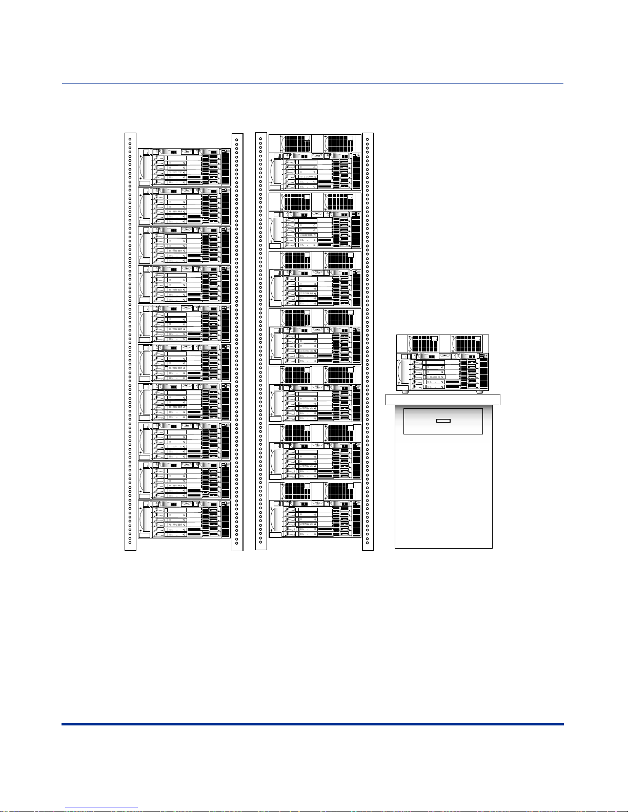
Mounting the CVX 600 in a Rack
Rack Capacity
You can install up to seven AC-powered CVX 600s or up to ten DC-powered
CVX 600s in a standard Telco or Electronic Industries Association (EIA) rack.
Rack Requirements
The rack must meet the following requirements:
• Heavy-duty steel construction
• EIA standard hole spacing, or a Telco rack with 25 mm spacing
Chassis Installation
Mounting the CVX 600 in a Rack
• Width of 19 in. (48.26 cm) or 23 in. (58.42 cm), depth of 24 in. (60.96 cm)
Nortel Networks Rack Recommendation
Nortel Networks recommen ds using a Physica l T ele communications Environment
(PTE) 2000 rack.
Caution: Nortel Networks does not authorize the use of racks with front
or rear doors or side panels. The operating environment must provide
airflow at 200 cubic feet per minute (CFM) per CVX 600 chassis at a
temperature range of 32° to 104°F (0° to 40°C). The optimal ambient
temperature for reliable CVX 600 operation is 68° to 77°F (20° to 25°C).
Rack Placement
The rack you plan to install should be in an area that is:
• A dedicated equipment room or closet, wired in accordance with local
electrical codes
• Large enough to allow easy access for service and maintenance
• Free of dust, smoke, and electrostatic discharge
296-1011-202 Rel. 5.0, Doc. Rev. 02.01 1-7
Page 28

CVX 600 Hardware Installation Guide
Mounting the CVX 600 in a Rack
• Properly ventilated
• Well lighted
Note: The recommended aisle spacing is 29.5 in. (750 mm).
Ceiling Requirements
Consider the following ceiling requirements before you install the rack:
• The ceiling should be clear of obstructions such as beams, heating and air
conditioning ducts, water pipes, and lights.
• The ceiling should not have sprinklers; however, appropriate fire protection
devices should be available.
Size and Weight Considerations
Before you install the rack at yo ur site, make sure that the equipment room can
accommodate the size and weight of the rack and the CVX 600.
T o de termine t he total weight, a dd the weight of all of the CVX 600 chassis (about
70 lb, 31.7 kg each for the AC chassi s opti on, NTDZ10BA)
rack.
Reference
For information a bout general equipment re quirements, s ee the Telcordia Network
Equipment Building St andards (NEBS), General Equipment Requirements
(GR-63).
Nortel Networks PTE 2000 Rack
Nortel Networks offers two types of PTE 2000 racks:
• PTE 2000 NEBS-compliant rack (NTRU0134)
, and the weight of t he
• PTE 2000 ETSI-compliant rack (NTRU0234)
1-8 296-1011-202 Rel. 5.0, Doc. Rev. 02.01
Page 29
Chassis Installation
Mounting the CVX 600 in a Rack
Reference
For PTE 2000 rack installation instructions, see the PTE 2000 Installation Guide
(IM 07-08-1543).
Anchor Kits
Nortel Networks offers four types of PTE 2000 anchor kits; each kit contains two
anchors. If you do not plan to order anchor kits from Nortel Networks, you can
use other anchor kits that provide the same level of seismic protection.
Note: You must use six floor anchors to secure the PTE 2000 rack to the
equipment-room floor.
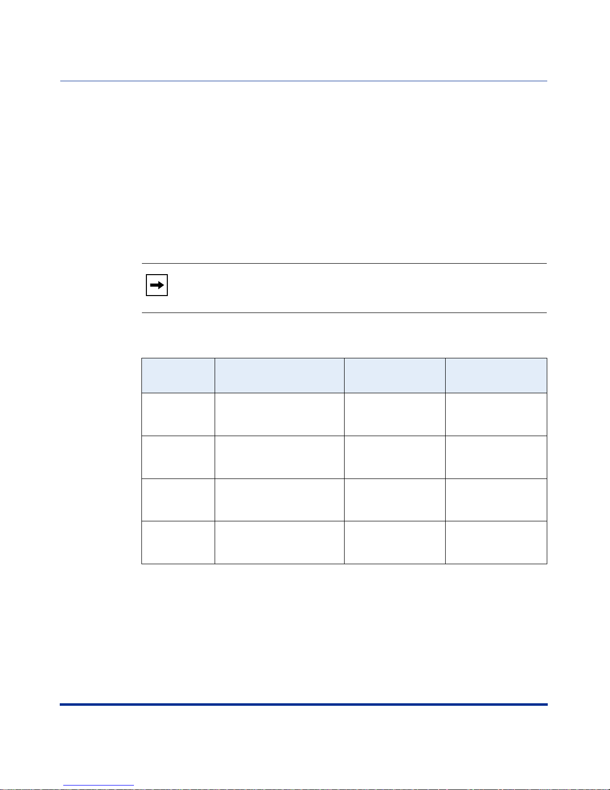
The following table describes each of the anchor kits.
Kit Number
NTRU0324 Up to and including zone 4 Raised or concrete
NTRU0328 Up to and including zone 4 Concrete floor only Includes M12
NTRU0323 Up to and including zone 2 Raised or concrete
NTRU0326 Up to and including zone 2 Concrete floor only Includes 3/8 in.
Earthquake Zone
Compliance
Floor Type Notes
Includes M12
floor
floor
anchoring hardware
(2 anchors)
anchoring hardware
(2 anchors)
Includes 3/8 in.
anchoring hardware
(2 anchors)
anchoring hardware
(2 anchors)
296-1011-202 Rel. 5.0, Doc. Rev. 02.01 1-9
Page 30
CVX 600 Hardware Installation Guide
Mounting the CVX 600 in a Rack
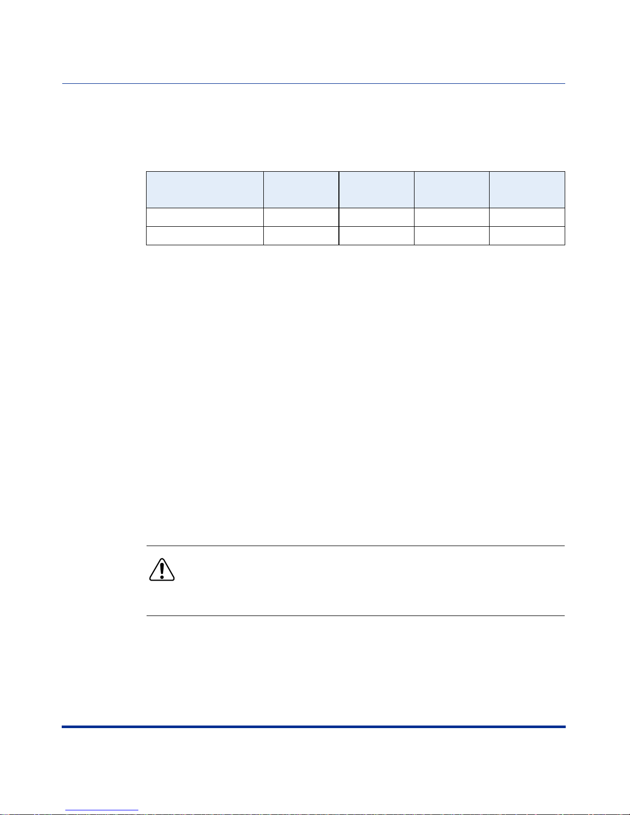
Space Requirements
The following table lists the PTE 2000 racks and dimensions.
Rack Type Part Number
NEBS-compliant rack NTRU0134 23.6 (600) 23.6 (600) 83.66 (2125)
ETSI-compliant rack NTRU0234 23.6 (600) 23.6 (600) 86.6 (2200)
Width in
Inches (mm)
Depth in
Inches (mm
Height in
Inches (mm)
Flooring Requirements
You must anchor the PTE 2000 rack to the equipment-room floor. The flooring
can be one of the following types:
• Raised floor tiles, ideally with a clearance of 18 in. (45.5 cm), and a subfloor
cable management system
• Bare concr ete floor
Depth for Drilling
If you plan to install the PTE 2000 floor anchors on a bare concrete floor, you
must drill to the following depths:
• 2 in. (51 mm) for the 3/8 in. anchor (for zone 2 earthquake compliance,
NTRU0323/NTRU0326)
• 4 in. (103 mm) for the M12 anchor (for zone 4 earthquake compliance,
NTRU0324/NTRU0328)
Warning: Before you begin to drill, make sure you are familiar with the
building construction. If you plan to drill holes in a below-ground
structure, make sure that you do not drill through the concrete into the
vapor barrier. If you do, groundwater may seep through the anchor hole.
1-10 296-1011-202 Rel. 5.0 , Doc. Rev. 02.01
Page 31

Access Considerations
The doorways, corr idors, and eleva tors leading to the install ation si te must be able
to accommodate the rack. Consider the following when planning the arrival and
unloading of the PTE 2000 rack:
• Including the pallet on which the PTE 2000 rack is shipped, the height of the
rack is 91.66 in. (2,325 mm). The pallet width is 39.4 in. (1,000 mm).
• The weight of an empty PTE 2000 rack is approximately 125 lb (57 kg),
excluding the shipping crate.
• Use freight elevators (if available) to move the equipment to upper floors.
Rack Cooling Requirements
You can install up to seven AC-powered CVX 600s or up to ten DC-powered
CVX 600s in a standard Telco or EIA rack without front or rear doors or side
panels. Nortel Networks recommends using a PTE 2000 rack.
Chassis Installation
Mounting the CVX 600 in a Rack
To ensure proper cooling for the CVX 600, the rack must meet the following
requirements:
• The operating environment must provide airflow at 200 CFM per CVX 600
chassis at a temperature range of 32° to 104°F (0° to 40°C).
• The optimal ambient temper ature for rel iable long-ter m CVX 600 operation is
68° to 77°F (20° to 25°C).
296-1011-202 Rel. 5.0, Doc. Rev. 02.01 1-11
Page 32

CVX 600 Hardware Installation Guide
AC and DC Power
AC and DC Power
Description
The CVX 600 uses either an AC or DC power source.
AC Power Option
If you are using AC power f rom an out let, you should be ins tall ing th e AC chas sis
option. The AC chassis option contains two independent power modules. If one
module fails, the other module powers the CVX 600.
AC Chassis Option
AC PM
AC PM 1 AC PM 2
AC PM
CVX-6oo
BIP
2
1
PCMCIA
2
1
PCMCIA
BIP
Fans
PDU 1
1
2
3
4
SCC
5
SCC
6
I
O
Filler
Good
Redun
Modem/ISDN
Fail
Pwr
Good
Redun
Modem/ISDN
Fail
Pwr
Good
Redun
RED
YEL
6
9
1
4
5
7
8
2
3
DAC DS1x12
System
System
10
12
11
Fail
Pwr
Good
Redun
Fail
Pwr
Good
Redun
Fail
Pwr
RESET
3
2
1
10/100 Enet
HSSI
RESET
3
2
1
10/100 Enet
HSSI
PDU 2
ESD
Jack
I
O
CVX-0237B
1-12 296-1011-202 Rel. 5.0 , Doc. Rev. 02.01
Page 33

Chassis Installation
AC and DC Power
DC Power Option
If you are using an external AC power supply, you should be installing the DC
chassis option.
The DC chassis option requires an external -48 VDC power source.
DC Chassis Option
CVX-6oo
BIP
2
1
PCMCIA
2
1
PCMCIA
BIP
Fans
PDU 1
1
2
3
4
SCC
5
SCC
6
Filler
Modem/ISDN
Modem/ISDN
DAC DS1x12
System
System
I
O
Good
Redun
Fail
Pwr
Good
Redun
Fail
Pwr
Good
Redun
RED
YEL
6
9
1
4
5
7
8
2
3
10
11
Fail
Pwr
Good
Redun
Fail
Pwr
Good
Redun
Fail
Pwr
12
RESET
3
2
1
10/100 Enet
HSSI
RESET
3
2
1
10/100 Enet
HSSI
PDU 2
ESD
Jack
I
O
CVX-0238B
Note: Both versions contain internal circuit breaker modules.
296-1011-202 Rel. 5.0, Doc. Rev. 02.01 1-13
Page 34

CVX 600 Hardware Installation Guide
Preparing for the CVX 600 Installation
Preparing for the CVX 600 Installation
Overview
To prepare for the installation of the CVX 600 chassis, make sure:
• The shipment is complete and undamaged.
• You have the proper equipment and tools.
• You have network lines available.
Unpacking the Shipment
The CVX 600 is secured to a pallet and covered by a box to protect the contents
during shipment. Move the shipping container to the installation site before
unpacking the CVX 600.
To unpack the CVX 600, follow these steps:
Step Action
1 Using a screwdriver or other too l, pry down the tabs that se cur e the box to the
pallet.
CVX-0182B
2 Lift the box up and off the pallet.
1-14 296-1011-202 Rel. 5.0 , Doc. Rev. 02.01
Page 35

Chassis Installation
Preparing for the CVX 600 Installation
Step Action
3 Remove the box cont aining the acce ssory kit and other p arts. (The AC chassis
option will have two power cords. The DC chassis option will have none.)
4 Remove the packing materi al surrounding the chassis.
5 Using a Phillips screwdriver, remove the six screws that secure the chassis to
the pallet brackets.
Turn counterclockwise
to remove screws.
AC PM
AC
PM
1
A
Fans
PDU 1
BIP
1
2
3
4
5
6
C PM 2
O
I
CVX 6oo
Filler
d
Faile
Redun
r
ISDN
d
Powe
oo
G
d
e
l
un
d
Fai
Re
r
Modem
owe
P
Good
d
e
Fail
edun
R
DS1
Yellow Red
Power
Good
1
2
3
4
5
6
7
8
d
9
e
n
u
ail
d
F
e
10
R
11
12
2
r
e
System
w
Ethernet
d
o
P
oo
G
1
3
HSSI
1
2
Reset
ed
l
dun
Fai
e
R
2
PCMCIA
1
System
Ethernet
od
Power
o
G
1
3
HSSI
1
2
Reset
PCMCIA
1
A
C
PM
BIP
PDU 2
O
E
SD
I
Jack
Phillips screwdriver
6 Using a 9/16-inch wrench, remove the four bolts that secure the pallet
brackets to the pallet.
7 Remove the four pallet brack et s from the p al let .
8 Carefully remove the chassis from the pallet.
Checking the Shipment
Carefully inspect the shipment for completeness, ensuring the items in the
shipping container match those on the packing list affixed to the shipping
container. In particular:
• Confirm that the shipment includes any additional cables you have ordered.
• Check all items for shipping d amage.
Phillips screwdriver
Turn counterclockwise
to remove screws.
CVX-0221A
Note: If you detect or suspect any damage, do not install the CVX 600
chassis. See “Te chn ic al Support” on page xviii.
296-1011-202 Rel. 5.0, Doc. Rev. 02.01 1-15
Page 36

CVX 600 Hardware Installation Guide
Preparing for the CVX 600 Installation
Tools and Equipment Needed
Before you install the CVX 600 chassis, ensure that you have all of the necessary
tools, cables, console equipment, and mounting hardware.
Tools
You must have the following tools:
• Screwdrivers:
— Phillips #2 screwdriver
— 1/16-inch and 1/4-inch flat-tip screwdrivers
• Nut drivers (nonmetric sizes) for securing power and ground cabling
• Volt/ohm meter for power connections
Cables and Cable Ties
The ship ment does not include the cables required for the telephone side of your
network. Ensure that the installation site has the proper network cabling.
Cable ties are needed to bundle network and power cables, to provide access to
LTM and RLTM modules.
Service Console
You can connect a local terminal or a PC to the CVX 600 to monitor startup
diagnostics and to perform manual startup and configuration. See Chapter 2,
“Chassis Connections,” for information on installing a service console. See the
following software manuals for information on configuring the CVX 600 access
switch:
• CVX Multi-Service Acc ess Switch Startup Guide
• CVX Multi-Se rvice Access Switch Configuration Guid e
1-16 296-1011-202 Rel. 5.0 , Doc. Rev. 02.01
Page 37

Chassis Installation
Preparing for the CVX 600 Installation
Note: Before you turn on the CVX 600, you should connect a local
terminal or PC to the CVX 600 console port. This console will display
diagnostic information. If there is a startup problem, in which case, you
need to contact Nortel Networks Technical Support (see “Customer
Services” on page xviii).
Mounting Hardware
To install the CVX 600 chassis i n a rack , you n eed a Phi llips #2 s crewdri ver an d a
computer rack that meets the specifications listed in “Rack Requirements” on
page 1-7.
If the rack does not have threaded rail holes, you must use cagenuts and cagenut
screws (not supplied).
296-1011-202 Rel. 5.0, Doc. Rev. 02.01 1-17
Page 38

CVX 600 Hardware Installation Guide
Installing the CVX 600 Chassis
Installing the CVX 600 Chassis
Mounting Options
You can mount the CVX 600 in one of two ways:
• Position the chassis on a flat, sturdy, horizontal surface.
• Mount the chassis in a rack.
Positioning the Chassis on a Flat Surface
When positioning the chassis on a flat, sturdy surface, you must ensure that the
surface is:
• Large enough for the chassis to operate properly
• Strong enough to support the combined weight of the chassis and the cables
1-18 296-1011-202 Rel. 5.0 , Doc. Rev. 02.01
Page 39

Installing the CVX 600 Chassis
Installing the Feet on the Bottom of the Chassis
To install the feet, follow these steps:
Step Action
1 Carefully lay the chassis on one side.
2 Using a Phillips screwdriver, attach the feet to the four holes in the bottom of
the chassis, near the corners.
ESD
AC PM
Jack
PDU 2
I
I
O
O
Chassis Installation
BIP
AC PM 1 AC PM 2
CVX-6oo
AC PM
I
I
O
O
Redun
Good
Failed
Filler
Power
ISDN
BIP
PDU 1
1
Fans
2
2
1
PCMCIA
2
1
PCMCIA
12
11
10
Reset
9
8
Reset
7
6
5
1
HSSI
4
1
3
HSSI
2
Redun
1
Good
Failed
Yellow Red
3
Redun
2
Power
1
Good
Failed
Modem
3
3
Ethernet
Power
Redun
2
1
Good
Failed
DS1
Ethernet
Redun
Power
Good
Failed
System
Power
System
4
5
6
CVX-0239A
296-1011-202 Rel. 5.0, Doc. Rev. 02.01 1-19
Page 40

CVX 600 Hardware Installation Guide
Installing the CVX 600 Chassis
Mounting the Chassis in a Rack
The mounting flanges are preinstalled on the chassis.
Caution: Nortel Networks recommends using a PTE 2000 rack. Nortel
Networks does not authorize the use of racks with front or rear doors or
side panels. The operatin g environment must provide airflow at 200 cubic
feet per minute (CFM) per CVX 600 chassis at a temper ature range of 32°
to 104°F (0° to 40°C). The optimal ambient temperature for reliable
CVX 600 operation is 68° to 77°F (20° to 25°C).
Caution: Before you install the CVX 600 chassis in a rack, ensure that
the rack is sturdy and well secured. A fully configured CVX 600 chassis
weighs about 70 lb, which could make an unsecured rack top-heavy or
unstable.
1-20 296-1011-202 Rel. 5.0 , Doc. Rev. 02.01
Page 41

Telco and EIA Rack Hole Spacing
You can use mounting flanges to install the CVX 600 chassis in a Telco or EIA
rack. Telco and EIA racks have 0.5-inch spacing between the dual mounting
holes, and 0.625-inch spacing between the dual mounting hole pairs.
The following figure shows the positions on the mounting flange that you use for
Telco and EIA racks.
Chassis Installation
Installing the CVX 600 Chassis
AC chassis option
DC chassis option
1
2
3
4
5
EIA: Use positions 2 and 4
TELCO: Use positions 1, 3, 5
1
2
3
4
5
6
7
EIA: Use positions 1, 3, 5, 7
TELCO: Use positions 2, 4, 6
CVX-0222A
Note: Before you instal l the CVX 600 chassis in a rack, dete rmine the
type of rack you have so that you can properly align the mounting holes.
296-1011-202 Rel. 5.0, Doc. Rev. 02.01 1-21
Page 42

CVX 600 Hardware Installation Guide
Installing the CVX 600 Chassis
Hardware Needed to Complete the Chassis Installation
To complete the chassis installation, you need the following hardware:
• Four (for DC chassis option) or eight (for AC chassis option) truss-head
mounting screws (included in the shipment)
• Phillips #2 screwdriver
Caution: A fully configured CVX 600 chassis can weigh about 70 lb.
You should have someone assist you in lifting and holding the chassis in
position at installation time.
1-22 296-1011-202 Rel. 5.0 , Doc. Rev. 02.01
Page 43

Installing the Chassis
To install the chassis, follow these steps:
Step Action
1 Have someone help you lift the chassis to the desired installation height.
2 Move the chassis up or down to properly align the positions on the mounting
flanges with the mounting holes on the rack.
Chassis Installation
Installing the CVX 600 Chassis
AC PM
AC PM 1
Fans
PDU 1
BIP
1
Filler
2
3
4
5
6
Failed
Redun
ISDN
Power
Good
Failed
Redun
Modem
Power
Good
Failed
Redun
DS1
Yellow Red
Power
ood
G
1
Failed
Redun
2
System
Ethernet
Power
Good
1
Failed
Redun
2
System
Ethernet
Power
Good
1
AC PM 2
AC PM
O
I
2
3
4
5
3
3
BIP
CVX 6oo
6
7
8
9
10
11
12
HSSI
1
2
Reset
PCMCIA
1
HSSI
1
2
Reset
PCMCIA
1
PDU 2
O
ESD
I
Jack
CVX-0240A
(continued)
296-1011-202 Rel. 5.0, Doc. Rev. 02.01 1-23
Page 44

CVX 600 Hardware Installation Guide
Installing the CVX 600 Chassis
Step Action
3 Insert truss-he ad s cre ws t hrough each flang e hol e a nd in to the correspond ing
holes on the front vertical supports of the rack.
AC PM
AC PM 1
Fans
PDU 1
BIP
1
2
3
4
5
6
Filler
n
Failed
Redu
ISDN
Power
Good
Failed
Redun
Modem
Power
Good
Failed
Redun
DS1
Yellow Red
Power
Good
1
Failed
Redun
2
System
Ethernet
Power
Good
1
Failed
Redun
2
System
Ethernet
Power
Good
1
AC PM 2
AC PM
O
I
2
3
4
5
6
3
HSSI
3
HSSI
BIP
CVX 6oo
7
8
9
10
11
12
1
2
Reset
PCMCIA
1
1
2
Reset
PCMCIA
1
PDU 2
O
ESD
I
Jack
Turn clockwise to
tighten screws
(75 in-lb for a
PTE 2000 rack).
4 Use a Phillips screwdriver to tighten the screws.
Caution: You must tighten the scr ews suff iciently to support the CVX
600 chassis. If using the PTE 2000 rack, tighten the p rovided h ex-head
screws to 75 in-lb, using a torque-regulating ratchet. Nortel Networks
cannot recommend a specific torque value for other racks.
CVX-0241A
1-24 296-1011-202 Rel. 5.0 , Doc. Rev. 02.01
Page 45

About This Chap te r
Introduction
This chapter describes how to connect network cabling and optional console
equipment to the CVX 600.
Chapter 2
Chassis Connections
Topics
This chapter covers the following topics:
Topic Page
Connecting Alarms 2-2
Connecting Network Cables 2-7
Connecting Power to the Chassis 2-16
Routing the Cables 2-27
Installing and Removing the Flash Memory Cards 2-29
Connecting Equipment to the Console Port 2-32
Connecting Equipment to a Local Ethernet Port 2-41
Applying Power to the CVX 600 2-42
Checking the LEDs 2-43
296-1011-202 Rel. 5.0, Doc. Rev. 02.01 2-1
Page 46

CVX 600 Hardware Installation Guide
Connecting Alarms
Connecting Alarms
Introduction
The SCC-LTM and SCC-RLTM contain a terminal block that allows you to
connect up to thre e audib le al arms and thr ee vi sual a larms. Th ese al arms al ert y ou
to critical, major, and minor conditions. The left six screw te rminals on the
terminal block are available for visual alarms, such as lights; the right six screw
terminals are availa ble for audible alarms, such as bells.
Warning: The contacts on the terminal block are rated at 30 VAC and
have a maximum current rating of 1 ampere (A). The circuit connecting
the alarms must meet the requirements for safety extra-low voltage
(SELV). The wires connecting the alarms must be the appropriate gauge
for alarm devices.
During normal, uninterrupted operation, the contacts remain open. If a failure
occurs, the contacts close and trigger the connected alarm.
Alarm Categories
The following table lists the three general categories of alarms and the possible
causes:
Alarm Possible Cause
Critical (Crit) Hardware failures: the system power supply and fan module have
Major (Maj) Communication failures: the link or network connection has failed.
Minor (Min) Modem failures: the configured thresholds have been exceeded.
failed, for example.
2-2 296-1011-202 Rel. 5.0, Doc. Rev. 02.01
Page 47

Alarm Types
Chassis Connections
Connecting Alarms
The following table lists specific alarm types, severity, and possible causes:
Alarm Type Severity Description
T1 Alarm Critical An alarm condition has been detected on the
specified T1 line, or the signal on the T1 line has
been lost.
T3 Alarm Critical An alarm condition has been detected on the
specified T3 line, or the signal on the T3 line has
been lost.
HSSI Port Down Critical The HSSI port has failed to initialize.
Ethernet Port
Down
Fan Down Major The cooling fans have stopped.
Power Down Major The external power source has dropped.
SCC Failover Major The primary SCC ha s failed, and th e secondary SCC
Link Down Minor The sending protocol entity recognizes a failure in
Slot Down Minor Communication has bee n lo st bet we en the ind ic ate d
Sonet/SDH
Loss of Si gnal
Sonet/SDH
Loss of Frame
Sonet/SDH C2
Mismatch
Major The Ethernet port has failed to i nitialize.
has resumed operation. CVXView generates this
alarm. Although the raising trap is generated on the
CVX 600, it does not recognize this as an alarm
condition. This alarm must be cleared manually on
CVXView (Clear Alarms button).
one of the communication links represented in the
agent’s configuration.
slot and the SCC.
Major Transitions are not detected on incoming signals,
therefore, a loss of signal is declared.
Major An OOF/SEF defect has persisted for a period of 3
milliseconds, therefore, a loss of frame is declared.
Minor The C2 field value in the received frame does not
match the configured value in the SigLabelExpect
attribute.
Sonet/SDH S1
New Event
296-1011-202 Rel. 5.0, Doc. Rev. 02.01 2-3
Minor The specified STM-1 is in S1 New Alarm. The S1
field in the received frame contains a new value.
(continued)
Page 48

CVX 600 Hardware Installation Guide
Connecting Alarms
Alarm Type Severity Description
Sonet/SDH S
Trace Mismatch
Minor The Section Trace string in the received frame does
not match the configured value in the
StraceStringExpect attribute.
Sonet/SDH P
Trace Mismatch
Minor The Path Trace st ring in th e receiv ed fram e does not
match the configured value in the
PtraceStringExpect attribute.
Sonet/SDH LOS
Major The LOS alarm condition is cleared.
Alarm Clear
Sonet/SDH LOF
Major The LOF ala rm condition is cleared.
Alarm Clear
APS Live Minor The designated optical interface is up and can
received calls.
APS Standby Minor The designated optical interface is up, but is in
standby mode.
APS Down Minor The designated optical interface is down.
ATM Red Alarm Major The specified link port has a critical alarm, such as
the absence of a line signal.
ATM Yellow
Major The specified link port has an informational alar m.
Alarm
ATM Alarm
Major The specified link po rt alarms are cleared.
Clear
ATM Marker
Minor The STIC Marker port is up.
Port Up
ATM Marker
Minor The STIC Marker port is down.
Port Down
ATM Interface UpMinor The ATM interface is up.
ATM Interface
Minor The ATM interface is down.
Down
ATM Logical
Minor The logical interface on the ATM interface is up.
Interface Up
ATM Logical
Minor The logical interface on the ATM interface is down.
Interface
ATM ILMI
Minor The ILMI interface i s up.
Enabled
ATM ILMI
Minor The ILMI interface i s down.
Disabled
2-4 296-1011-202 Rel. 5.0, Doc. Rev. 02.01
Page 49

Alarm Type Severity Description
Chassis Connections
Connecting Alarms
ATM PVPC
PVCC Up
ATM PVPC
PVCC
ATM APS
Switchover
Sonet/SDH
Alarm Sdber
Sonet/SDH
Alarm Sfber
Sonet/SDH
Alarm Sdber
Clear
Sonet/SDH
Alarm Sfber
Clear
Minor The PVPC/PVCC has been successfully created.
Minor The PVPC/PVCC is down.
Minor A link failure caused the PHY driver to turn on the
redundant PHY.
Major The specified STM-1 is in Signal Degrade Bit Error
Rate alarm. The value set in the
SigDegradeThreshold attribute for this line has
been exceeded.
Major The specified STM-1 is in Signal Failure Bit Error
Rate alarm. The value set in the
SigFailureThreshold attribute for this line has been
exceeded.
Major The specified STM-1 is not in Signal Degrade Bit
Error Rate alarm. The Signal D egra de Bit Error Ra te
is now below the SigDegradeThreshold value set in
the configuration.
Major The specified STM-1 is not in Signal Fai lure Bit Error
Rate alarm. The Signal Failure Bit Error Rate is now
below the SigFailureThreshold value set in the
configuration.
Reference
For pinout assignments, see Appendix A, “Technical Specifications.”
296-1011-202 Rel. 5.0, Doc. Rev. 02.01 2-5
Page 50

CVX 600 Hardware Installation Guide
Connecting Alarms
Procedure
To connect alarms to the termin al block, fo llow these steps:
Step Action
1 Select the terminals you want to use for the audible or visual alarm.
2 Use a small flat-tip screwdriver to loosen the two terminal screws for each
alarm device you want to connect. For example, if you want to connect an
audible alarm for a critical condition, loosen the terminal screws for the
terminals labeled Crit(ical) and Ret(urn).
RX
OC3/STM1-1
TX
Alarms
Visual
Console
SCC-RLTM
Redundant
System
Ret
Min
Ret
Maj
Ret
Crit
Ret
Min
Ret
Maj
Audible
Ret
Crit
Remove 1/2 inch
of wire insulation.
Connect wires
RX
OC3 /STM1-1
TX
Alarms
Visual
Ret
Remove 1/2 inch
of insulation.
Connect wires
to alarm device.
to alarm device.
Min
Ret
Maj
Ret
Crit
Ret
Min
Ret
Maj
Tighten screws to
1 to 2 in-lb, using a
1/16-inch flat-tip
screwdriver.
Audible
Ret
Crit
Tighten screws to 1 to 2 in-lb
using a 1/16-inch flat-tip
screwdriver.
Optical SCC-II-LTM
Console
OC3/STM1
System
CVX-0184C
3 Use a wire stripper to remove approximately 1/2 inch of insulation from the
wires.
4 Insert the wires in to the te rminal s and t ighten the sc rews t o 1 to 2 i n-lb us ing a
1/16-inch flat-tip screwdriver.
5 Connect the other end of the wires to the alarm device.
2-6 296-1011-202 Rel. 5.0, Doc. Rev. 02.01
Page 51

Connecting Network Cables
Overview
You will need to attach network cables to the following CVX 600 interfaces:
• 10/100BASE-T (on the SCC-LTM and SCC-RLTM)
• DS1/T1 (RJ-45/48C)
• E1 (RJ-45/48C)
• DS3
• HSSI
• Optical (OC3/STM1)
Chassis Connections
Connecting Network Cables
Reference
See Appendix A, “Technical Specifications” for descriptions of the CVX 600
cable interfaces.
296-1011-202 Rel. 5.0, Doc. Rev. 02.01 2-7
Page 52

CVX 600 Hardware Installation Guide
Connecting Network Cables
Connecting to 10/100BASE-T Interfaces
Each 10/100BASE-T interface on the SCC-RLTM supports one full-duplex
connection.
To connect an Ethernet unshielded twisted pair (UTP) cable to a
10/100BASE-T interface, follow these steps:
Step Action
1 Plug the UTP connectors into the receptacles.
3
10/100 Enet
2
10/100 Enet
RX
Link
RX
5
10/100 Enet
RX
Link
1
4
Link
RX
10/100 Enet
10/100 Enet
Link
3
RX
Link
RX
Link
RX
OC3/STM1-2
10/100 Enet
TX
RX
TX
Alarms
10/100 Enet
RX
1
Link
Visual
Ret
10/100 Enet
Min
Alarms
Visual
Ret
Maj
Ret
Crit
Ret
Min
OC3/STM1-1
2
RX
Link
Optical SCC-II-LTM
Ret
Audible
Min
Ret
Maj
Ret
Console
Crit
5XEthernet SCC-RLTM
Ret
Maj
Ret
Crit
Ret
Min
Ret
Maj
Ret
Crit
OC3/STM1
System
APPAXXX A LASER
DE CLASSE 1
Audible
LASER PRODUCT
CLASS 1
HSSI
3
10/100 Enet
2
RX
Link
10/100 Enet
1
10/100 Enet
Alarms
RX
Link
Visual
RX
Link
3XEthernet SCC-RLTM
Ret
Min
Ret
Maj
Ret
Crit
Ret
Min
Audible
Ret
Maj
Ret
Crit
CVX-0199B
2-8 296-1011-202 Rel. 5.0, Doc. Rev. 02.01
Page 53

Connecting to DS1/T1 Interfaces
The DS1-DAC-LTM provides 12 or 24 channelized T1 ports and one port for
connecting to an external clocking device.
To connect T1 cables to the T1 ports, and to connect the DS1-DAC-LTM to an
external clocking device, follow this step:
Step Action
1 Plug the connectors into the receptacles.
Connect to the
external clocking
device (optional).
Chassis Connections
Connecting Network Cables
Clock
12
11
10
9
8
7
6
5
4
3
2
12 DS1 ports
DS112
1
Connect to the
external clocking
device (optional).
24
Clock
12
Connect to the
telephone network.
21
20
9
8
17
16
5
4
24 DS1 ports
13
E 1 x 24
1
CVX-0242A
296-1011-202 Rel. 5.0, Doc. Rev. 02.01 2-9
Page 54

CVX 600 Hardware Installation Guide
Connecting Network Cables
Connecting to E1 Interfaces
The E1-DAC-LTM provides 12 or 24 E1 ports and one port for connecting to an
external clocki ng device. To connect E1 cables to t he E1 ports, and to connect the
E1-DAC-LTM to an external clocking device, follow this step:
Step Action
1 Plug the connectors into the receptacles.
Connect to the
external clocking
device (optional).
Connect to the
external clocking
device (optional).
Clock
12
11
10
9
8
7
6
5
24
Clock
12
21
20
9
8
17
16
5
4
4
3
12 E1 ports
E 112
2
1
24 E1 ports
13
E 1 x 24
1
Connect to the
telephone network.
CVX-0243A
Note: Using sh ielded cab ling is an ele ctromagnetic interference (EMI)
requirement for CVX 600 E1 network configurations.
Note: For UK installations using 75 ohm E1 coax, a balun is needed to
connect to the 120 ohm impedance of the CVX switch. Nortel does not
recommend a specific balun panel for this application.
2-10 296-1011-202 Rel. 5.0 , Doc. Rev. 02.01
Page 55

Connecting to DS3 Interfaces
To connect to DS3 interfaces, follow this ste p:
Step Action
1 Plug the TX and RX coaxial cable connectors into the appropriate
DS3 receptacles on the SCC or DAC.
Chassis Connections
Connecting Network Cables
3
10/100 Enet
2
RX
TX1
RX2
TX2
RX1
TX1
R
TX2
TX1
Rx
Tx
10/100 Enet
Link
RX
Link
RX
Clock Ref
2xDS3-SCC-RLTM
1
10/100 Enet
Alarms
Visual
Ret
Link
Min
Ret
Maj
Ret
Crit
2xDS3-DAC-RLTM
Clock Ref
2xDS3-DAC-LTM
Ret
DS3
Min
Ret
DS3
Audible
Maj
Ret
Crit
DS3
DS3 Redundant
DS3
DS3-DAC-RLTM
Clock Ref
Rx
Tx
DS3
DS3 Redundant
DS3
296-1011-202 Rel. 5.0, Doc. Rev. 02.01 2-11
Connect to
the telephone
network.
Clock Ref
Connect to the
external clocking
device (if used).
DS3-DAC-LTM
DS3
DS3
CVX-0200A
Page 56

CVX 600 Hardware Installation Guide
Connecting Network Cables
Connecting to the HSSI Interface
The SCC-HSSI-RLTM contains one HSSI 50-pin inter face rece ptacl e. To connect
a HSSI cab le, follow this step:
Step Action
1 Plug the cable connector into the HSSI interface receptacle.
HSSI
3
10/100 Enet
RX
Link
2
10/100 Enet
RX
Link
1
10/100 Enet
RX
Link
Connect the other end of this
cable to the router or network
switching device.
CVX-0201A
2-12 296-1011-202 Rel. 5.0 , Doc. Rev. 02.01
Page 57

Connecting to the OC3/STM1 Interface
The Optical DAC-LTM contains two sets of optical ports (two primary and two
redundant, each with separate Tx and Rx channels), consisting of a total of eight
optical connections. The Optical SCC-II-LTM contains two sets, with separate Tx
and Rx channels, consisting of a total of four optical connections.
Connections may be made to optical cables with SC single or SC duplex
connectors.
Warning: These devices contain Class 1 laser products, and comply
with 21 CFR 1040.10 and 1040.11 EN 60825-1 - Safety of Laser
Products.
Class 1 lasers are considered eye-safe; however, follow these
appropriate safety measures:
• Always make sure that the CVX switch is powered down before
connecting or disconnecting any optical cables.
• Always make sure all ports or unconnected optical cable ends are
covered before powering up the CVX switch.
• Never remove a cover from a port or attached optical cable while the
CVX switch has power.
Chassis Connections
Connecting Network Cables
Caution: For proper operation, observe the following:
• Never touch the end of the fiber in a connector with anything except
an approved cleaner.
• Always clean the end of the fiber in connectors and optical ports
before connecting the cables. Use an approved cleaner, or a soft cloth
with isopro pyl alcohol.
• Never use any optical cable that has been damaged, or that has been
coiled tighter than a 35-mm radius curve.
296-1011-202 Rel. 5.0, Doc. Rev. 02.01 2-13
Page 58

CVX 600 Hardware Installation Guide
Connecting Network Cables
Connecting an Optical Cable
To connect an optical cable, follow these steps:
Step Action
1 Remove the rubber plugs from each pair of ports.
1
Rx
Link
RX
TX
RX
OC3/STM1-2
OC3/STM1-1
TX
Alarms
Visual
Ret
Min
Ret
Maj
Ret
Crit
Optical SCC-II-LTM
Ret
Min
Audible
Ret
Maj
Ret
Crit
Console
OC3/STM1
System
APPAXXX A LASER
LASER PRODUCT
DE CLASSE 1
CLASS 1
Tx
B
Rx
B
Tx
A
Rx
A
Tx
B
Rx
2
B
1
Optical DAC-LTM
Tx
A
Rx
A
STMx2
APPAXXX A LASER
LASER PRODUCT
DE CLASSE 1
CLASS 1
CVX-0139D
2-14 296-1011-202 Rel. 5.0 , Doc. Rev. 02.01
Page 59

Chassis Connections
Connecting Network Cables
Step Action
2 Remove the protective covers from each optical connector.
Remove cover.
Remove covers.
CVX-0138B
3 Orient the the optic al cable conn ector so th at the ta b aligns wit h the slot
in the port, and push the cable connector into the port.
1
Rx
Link
RX
TX
RX
TX
Alarms
Visual
OC3 A
Ret
Min
Connect to
the optical port.
Optical SCC-II-LTM
Ret
Maj
Ret
Crit
Audible
Ret
Min
Ret
Maj
Ret
Crit
Console
OC3
System
APPAXXX A LASER
LASER PRODUCT
DE CLASSE 1
CLASS 1
Clock Ref
Connect to the
external clocking
device (if used).
Tab
Tx
B
Tab
Rx
B
Tx
A
Rx
A
Tx
B
Rx
2
B
Optical DAC-LTM
Tx
A
Rx
A
1
OC3x2
APPAXXX A LASER
DE CLASSE 1
LASER PRODUCT
CLASS 1
Connect to the
optical port.
CVX-0140D
296-1011-202 Rel. 5.0, Doc. Rev. 02.01 2-15
Page 60

CVX 600 Hardware Installation Guide
Connecting Power to the Chassis
Connecting Power to the Chassis
Before You Start
Make sure you can power the CVX 600 using one of the following power s ourc es:
• A customer-supplied DC power source with frame grounding (for the DC
chassis option)
• A built-in AC power module (for the AC chassis option)
Requirements
Before you connect the CVX 600 to power and ground at the installation site:
• Refer to your company or site specifications for information on the torque
requirements for securing power and ground cables.
• Make sure the switches on both circuit breaker modules (PDUs) are off (o).
Circuit breaker (PDU) switches
Fans
PDU 1
BIP
O
Modem/ISDN
DAC DS1x24
System
System
Modem/ISDN
Modem/ISDN
I
Good
Redun
Pwr
Fail
Good
Redun
Pwr
Fail
Good
Redun
Pwr
Fail
Good
Failed
Redun
Redun
RED
YEL
Yellow Red
Pwr
Power
Good
Fail
1
1
2
2
3
3
4
4
5
5
6
6
7
7
8
8
9
9
10
10
Good
Redun
Pwr
Fail
1
HSSI
2
10/100 Enet
3
Good
Redun
Pwr
Fail
1
HSSI
2
10/100 Enet
3
BIP
CVX 6oo
PDU 2
O
ESD
I
Jack
11
11
12
12
RED
YEL
13
14
15
16
17
18
19
20
RESET
RESET
21
22
23
24
2
PCMCIA
1
2
PCMCIA
1
CVX-0202B
1
2
3
4
5
6
• Read the “Safety Warnings” on page vii.
2-16 296-1011-202 Rel. 5.0 , Doc. Rev. 02.01
Page 61

Grounding the Chassis
Note: In addition to the grounding location shown in the following
sections, the AC chassis option also contains an identical grounding
location in the upper righ t corner of the rear of the ch assis. Ei ther loca tion
may be used.
There are two ways to ground the CVX 600 chassis:
• Use the NEBS-compliant dual-connector posts.
Chassis Connections
Connecting Power to the Chassis
System Redundant
Console
Ground cables
• Use the compression terminal.
System Redundant
Console
To facility ground
4
5
6
OR
4
5
6
CVX-0244A
296-1011-202 Rel. 5.0, Doc. Rev. 02.01 2-17
CVX_0245A
Page 62

CVX 600 Hardware Installation Guide
Connecting Power to the Chassis
Using the NEBS-Compliant Dual-Connector Post s
Note: In addition to the grounding location shown in the following
section, the AC chassis option also contains an identical grounding
location in the upper righ t corner of the rear of the ch assis. Ei ther loca tion
may be used.
To ground the CVX 600 chassis using the NEBS-compliant dual -co nnec to r posts,
follow these steps:
Step Action
1 Locate a suitable ground cable at your facility.
2 On the back of the chassis, locate the posts with the ground symbol.
3 Remove the #8 locking nuts, using a 11/32-inch nut driver to loosen the nuts.
Console
System Redundant
4
5
6
11/32-inch nutdriver
Turn counterclockwise
to loosen nuts.
CVX-0223A
4 Remove the connector assembly from the posts if you are using a ground
cable with a NEBS-compliant ground fitting.
2-18 296-1011-202 Rel. 5.0 , Doc. Rev. 02.01
Page 63

Chassis Connections
Connecting Power to the Chassis
Step Action
5 Place the grounding connectors over the posts, then secure the connectors
using a 11/32-inch nut driver to tighten the #8 locking nuts to 15 in-lb.
System Redundant
Console
11/32-inch nutdriver
Turn clockwise
to tighten nuts
to 15 in-lb.
Ground cable
to facility
ground.
4
5
6
OR
CVX-0224A
6 Ensure that the other end of the gro und cab le is properly connected for frame
grounding.
Using the Compression Terminal
Note: In addition to the grounding location shown in the following
section, the AC chassis option also contains an identical grounding
location in the upper righ t corner of the rear of the ch assis. Ei ther loca tion
may be used.
To ground the CVX 600 chassis using the compression terminal, follow these
steps:
Step Action
1 Locate a suitable ground cable at your facility.
2 On the back of the chassis, locate the posts with the ground symbol.
296-1011-202 Rel. 5.0, Doc. Rev. 02.01 2-19
(continued)
Page 64

CVX 600 Hardware Installation Guide
Connecting Power to the Chassis
Step Action
3 Use a flat-tip screwdriver to loosen the locking screw.
System Redundant
Console
4
5
6
1/4-inch flat-tip
screwdriver
Turn counterclockwise
to loosen screw.
CVX-0225A
4 Use a wire stripper to remove approximately 1/2 inch of insulation from the
ground cable.
5 Insert the stripped end of the wire into the compression terminal; ensure that
the wire is inserted between the retainer and the back of the connector. If the
screw comes in contact with the wire, remove the wire and insert it below the
retainer to ensure a proper ground connection.
System Redundant
Console
4
5
6
6 Use the flat-tip screwdriver to tighten the locking screw to 24 in-lb.
7 Ensure that the other end of the gro und cab le is properly connected for frame
grounding.
2-20 296-1011-202 Rel. 5.0 , Doc. Rev. 02.01
1/4-inch flat-tip
screwdriver
Turn clockwise
to tighten screw
to 24 in-lb.
To facility ground
CVX-0246A
Page 65

Connecting Power to the Chassis
Connecting to a Customer-Supplied DC Power Source
The customer-supplied DC power source is only for the DC chassis option.
Prerequisites
Before connecting the CVX 600 to a DC power source, see “DC Power Supply
Warnings” on page vii.
Caution: Ensure that the wire gauge you use is adequate for the distance
between the CVX 600 and the DC power source. Before connecting
power cables to the CVX 600, use a volt/ohm meter to ensure that the
power cables are not live.
Chassis Connections
296-1011-202 Rel. 5.0, Doc. Rev. 02.01 2-21
Page 66

CVX 600 Hardware Installation Guide
Connecting Power to the Chassis
Connecting to a DC Power Source
To connect to the power source, follow the se steps:
Step Action
1 Make sure the power switches on the PDUs are off.
Circuit breaker (PDU) switches
Fans
PDU 1
BIP
O
1
2
3
4
5
6
I
Good
Redun
Modem/ISDN
Pwr
Fail
Good
Redun
Modem/ISDN
Pwr
Fail
Good
Redun
Modem/ISDN
Pwr
Fail
Good
Failed
Redun
Redun
RED
DAC DS1x24
YEL
Yellow Red
Pwr
Power
Good
Fail
1
1
2
2
3
3
4
4
5
5
6
6
7
7
8
8
9
9
10
Good
Redun
System
Pwr
Fail
1
HSSI
2
10/100 Enet
Good
Redun
System
Pwr
Fail
1
HSSI
2
10/100 Enet
BIP
CVX 6oo
PDU 2
O
ESD
I
Jack
10
11
11
12
12
RED
YEL
13
14
15
16
17
18
19
3
3
20
RESET
RESET
21
22
23
24
2
PCMCIA
1
2
PCMCIA
1
2 Remove the clear cover by removing the three screws on the cover.
System
Controller
1
2
3
4
5
only
6
DC PM 2 DC PM 1
Rx
Clock
Clock
Tx
12
11
10
9
12
11
HSSI
10
3
10/100 Enet
RX
Link
8
7
6
9
2
10/100 Enet
1
RX
Link
RX
Link
5
8
7
6
5
10/100 Enet
Alarms
Visual
Ret
Min
Ret
Maj
Ret
Crit
Phillips
screwdriver
Turn counterclockwise
to loosen screws.
4
3
2
4
3
2
Audible
Ret
Min
Ret
Console
Maj
Ret
Crit
1
1
DS3
E 1 x 12
DS1 x 12
System Redundant
1
2
Main Chassis
3
4
5
6
3 Remove the nuts from the posts using a 3/8-inch nutdriver.
CVX-0202B
CVX-0203A
2-22 296-1011-202 Rel. 5.0 , Doc. Rev. 02.01
Page 67

Chassis Connections
Connecting Power to the Chassis
Step Action
4 Place the lugs of the wires over the posts. Make sure that the lugs for the
black wires are on the posts labeled “RETURN” on the raised brackets, and
that the lugs for the red wires are on the posts labeled “-48V” on the brackets
that are flush with the surface.
Black cable to "RETURN"
Red cable to "-48V"
9
8
7
9
2
10/100 Enet
Link
6
8
7
6
1
10/100 Enet
Alarms
Visual
RX
Ret
Link
Min
Black cable to "RETURN"
PDU 1 DC INPUT A
5
5
Ret
Maj
Ret
Crit
Ret
4
3
4
3
Min
Ret
Maj
Ret
Crit
Red cable to "-48V"
DC PM 1
DS3
E 1 x 12
2
1
DS1 x 12
2
1
Audible
Console
System Redundant
1
2
Main Chassis
3
4
5
6
Controller
System
PDU 2 DC INPUT B
1
2
3
4
5
only
6
DC PM 2
Rx
Clock
Clock
Tx
12
11
10
12
11
10
HSSI
3
10/100 Enet
RX
Link
RX
CVX-0204A
5 Tighten nuts to 13 in-lb using the nutdriver.
6 Secure the cab les usin g a ca ble ti e throu gh the ca ble m ount on the l ower righ t
side of the chassis.
(continued)
296-1011-202 Rel. 5.0, Doc. Rev. 02.01 2-23
Page 68

CVX 600 Hardware Installation Guide
Connecting Power to the Chassis
Step Action
7 Install the clear plastic protective cover, securing the cover with three screws.
Tighten the screws to 6 in-lb.
Tighten screws to 6 in-lb.
Next Step
DC PM 2 DC PM 1
Rx
Clock
Clock
Tx
12
11
10
9
12
11
10
HSSI
3
10/100 Enet
RX
Link
8
7
6
9
2
10/100 Enet
RX
Link
RX
5
8
7
6
5
1
10/100 Enet
Alarms
Visual
Ret
Link
Min
Ret
Maj
Ret
Crit
Ret
Min
Phillips
screwdriver
DS3
4
4
Ret
Maj
Ret
E 1 x 12
DS1 x 12
System Redundant
1
2
Main Chassis
3
4
5
6
3
2
1
3
2
1
Audible
Console
Crit
System
Controller
1
2
3
4
5
only
6
CVX-0205A
8 Connect the -48V and RETURN DC power cables to the DC power source.
To apply power, see “Applying Power to the CVX 600” on page 2-42.
2-24 296-1011-202 Rel. 5.0 , Doc. Rev. 02.01
Page 69

Connecting Chassis to an AC Power Source
The AC power source is only for the AC chassis option.
Connecting the Power Cords
To connect the power cords to the chassis, follow t hese steps:
Step Action
1 Make sure that the tw o po wer switc hes o n the circ uit bre aker modu les (PD Us)
are off.
Circuit breaker (PDU) switches
Chassis Connections
Connecting Power to the Chassis
AC PM
AC PM 1
AC PM 2
Fans
PDU 1
BIP
O
1
2
3
4
5
6
I
Filler
Failed
Redun
ISDN
Power
Good
Failed
Redun
Modem
Power
Good
Failed
Redun
DS1
Yellow Red
Power
Good
1
2
3
4
5
6
7
8
9
Failed
Redun
2
System
Ethernet
Power
Good
1
3
HSSI
1
Failed
Redun
2
System
Ethernet
Power
Good
1
3
HSSI
1
BIP
CVX 6oo
10
11
12
2
Reset
PCMCIA
1
2
Reset
PCMCIA
1
AC PM
PDU 2
O
ESD
I
Jack
CVX-0226A
(continued)
296-1011-202 Rel. 5.0, Doc. Rev. 02.01 2-25
Page 70

CVX 600 Hardware Installation Guide
Connecting Power to the Chassis
Step Action
2 Insert t he power cords into the receptacles labeled “AC PM2” and “AC PM1.”
AC PM 2
DC PM 2 DC PM 1
Rx
Tx
Clock
Clock
12
11
10
9
12
11
HSSI
3
10/100 Enet
RX
Link
8
7
10
9
2
10/100 Enet
RX
Link
6
5
8
7
6
5
1
10/100 Enet
Alarms
Visual
RX
Ret
Link
Min
Ret
Maj
Ret
Crit
Ret
AC PM 1
4
4
Min
Ret
DS3
E 1 x 12
Console
1
1
DS1 x 12
System Redundant
1
2
Main Chassis
3
4
5
6
3
2
3
2
Audible
Maj
Ret
Crit
System
Controller
only
AC power cords
1
2
3
4
5
6
CVX-0206B
3 Insert the other ends of the power cords into the AC power receptacle.
AC power cord
Next Step
To apply power, see “Applying Power to the CVX 600” on page 2-42.
2-26 296-1011-202 Rel. 5.0 , Doc. Rev. 02.01
Connect to a grounded 20 A
power source (100 to 240 VAC).
(North America: 120 V at 20 A)
(Europe: 240 V at 10 A)
CVX-0230A
Page 71

Routing the Cables
Cable Mounts
The CVX 600 chassis includes plastic cable mounts that you can use to position
the cables, using cable ties (not supplied), around the chassis. These mounts help
to ensure that the cables at the back of the chassis do not obstruct airflow and do
not obstruct the removal of LTMs and RLTMs.
Suggested Use
Typically, the cable mounts on the left are used to route communications cables,
while the one on the lower right is used to route power cables.
Chassis Connections
Routing the Cables
Locations of Cable Mounts
The following figure shows the location of the cable mounts.
AC PM 2
1
2
3
4
5
System
Controller
only
6
AC PM 1
PDU 2 DC INPUT B
Rx
Tx
Clock
Clock
HSSI
10
11
12
12
9
10
11
9
2
3
10/100 Enet
Link
RX
RX
7
8
7
8
1
10/100 Enet
10/100 Enet
Link
RX
Link
PDU 1 DC INPUT A
DS3
1
E 1 x 12
6
5
4
6
5
4
Alarms
Visual
Ret
Min
Ret
Maj
Ret
Crit
Ret
Min
Ret
Maj
Ret
1
2
3
1
2
3
Console
Audible
Crit
OC3/STM1
DS1 x 12
System
2
Main Chassis
3
4
5
6
CVX-0229A
296-1011-202 Rel. 5.0, Doc. Rev. 02.01 2-27
Page 72

CVX 600 Hardware Installation Guide
Routing the Cables
Routing Fiber Optic Cables
Introduction
The routing of fi ber optic cables re quires diff er ent considerations t han the routing
of wire cables, due to the delica te material of the tran smission l ine.
Minimum Radius
The following table gi ves the mini mum bend radius for se veral types of fiber optic
cable:
Cable/Fiber Type Number of Fibers
Simplex 1 35 mm 50 mm
Duplex 2 70 mm 140 mm
Quad 4 85 mm 160 mm
Minimum Bend Radius
(normal handling)
Minimum Bend
Radius (static load)
Note: The minimum radius must be maintained at all times, including
while routing the cable and managing slack cable.
Rack Standoff Brackets
To ensure that the fiber optic cable is properly secured to the chassis, a
rack-mounted bracket may be used to support the fiber optic cable. Nortel does
not supply a bracket for this purpose.
Securing and Wrapping Fiber Optic Cables
Fiber optic cables can be secured with tie wraps, if not applied too tightly. Your
application may also require the fiber to be wrapped in a protective paper. Tie
wraps must be fitted in accordance with Nortel Work Standards WS-001 and
WS-4024.
2-28 296-1011-202 Rel. 5.0 , Doc. Rev. 02.01
Page 73

Chassis Connections
Installing and Removing the Flash Memory Cards
Installing and Removing the Flash Memory Cards
Description
The SCC- SM contains dual PCMCIA slots for the flash memory card. The flash
memory card provides storage for the CVX 600 nonvolatile file system (NVFS),
operating system software, and configuration files. When you insert the flash
memory card, the NVFS automatically provides access to the flash memory card.
The dual PCMCIA slot s a re labeled 1 and 2. Sl ot 1 is the C: drive and sl ot 2 is the
D: drive. Always use slot 1 for the flash memory card. Use slot 2 if you need to
copy the flash memory card in slot 1 to a flash memory card in slot 2.
Reference
See the manual CVX Multi-Service Access Switch Configuration Guide for
information about copying a flash memory card.
Note: If the flash memory card is not already in the SCC, insert it into
slot 1.
Warning: You must use software Release 5.0 or later w hen using an
Optical SCC-II-SM. Use of older versions will corrupt the SCC-SM,
requiring the return of the module to Nortel for reprogramming. Do not
copy earlier versions of software to a flash memory card used in an
Optical SCC-II-SM.
296-1011-202 Rel. 5.0, Doc. Rev. 02.01 2-29
Page 74

CVX 600 Hardware Installation Guide
Installing and Removing the Flash Memory Cards
Inserting a Flash Memory Card
To insert a flash memory card, follow these steps:
Step Action
1 Position the card so that its label is facing up.
2 Insert the card into slot 1 and gently push the card until it clicks into position.
Good
Redun
System
Pwr
Fail
Good
Redun
System
Pwr
Fail
1
10/100 Enet
HSSI
2
3
1
10/100 Enet
4
5
RESET
2
PCMCIA
1
2
3
RESET
2
PCMCIA
1
CVX-0231A
2-30 296-1011-202 Rel. 5.0 , Doc. Rev. 02.01
Page 75

Removing a Flash Memory Card
To remove a flash memory card, follow these steps:
Step Action
1 Press the eject button next to the slot (labeled 1 or 2) from which you want to
remove a flash memory card.
Chassis Connections
Installing and Removing the Flash Memory Cards
Press the eject button
to release the flash memory
card.
System
System
Good
Redun
Pwr
Fail
1
10/100 Enet
2
3
4
5
RESET
RESET
PCMCIA
PCMCIA
2
1
2
1
Good
Redun
Pwr
Fail
1
HSSI
2
10/100 Enet
3
2 Pull the flash memory card out of the slot.
CVX-0232A
296-1011-202 Rel. 5.0, Doc. Rev. 02.01 2-31
Page 76

CVX 600 Hardware Installation Guide
Connecting Equipment to the Console Port
Connecting Equipment to the Console Port
Introduction
You can connect a terminal, PC, modem, or t erminal serv er to the CVX 600, using
the console port on the SCC.
The following procedures provide steps for connecting each piece of equipment:
•“Connecting a Terminal”
•“Connecting a PC”
• “Connecting a Modem”
• “Connecting a Terminal Server”
Note: Once you have connected this equipment, you can then edit your
system configuration.
2-32 296-1011-202 Rel. 5.0 , Doc. Rev. 02.01
Page 77

Connecting a Terminal
To connect a terminal to the CVX 1800 using the DB-9 to DB-9 cable, follow
these steps:
Step Action
1 Turn on the terminal, then configure it using the parameters listed
Chassis Connections
Connecting Equipment to the Console Port
below.
Reference: For instructions, see the documentation for the terminal or
the terminal emulation program.
Parameter Value
Terminal type VT-100
Baud rate 19200
Connect using Direct to COM 1
Flow control None
Data bits 8
Stop bits 1
Parity None
2 Turn off the terminal.
(continued)
296-1011-202 Rel. 5.0, Doc. Rev. 02.01 2-33
Page 78

CVX 600 Hardware Installation Guide
Connecting Equipment to the Console Port
Step Action
3 Attach the 9-pin recep t ac le end of the conso le ca ble to the console
port.
System
Controller
AC PM 2
PDU 2 DC INPUT B
Rx
1
2
3
4
5
only
6
Clock
Clock
Tx
10
11
12
12
HSSI
9
8
10
11
9
8
2
3
10/100 Enet
Link
RX
1
10/100 Enet
10/100 Enet
Link
RX
Link
RX
PDU 1 DC INPUT A
6
7
5
6
7
5
Alarms
Visual
Ret
Min
Ret
Maj
Ret
Crit
Ret
Min
2
3
4
2
3
4
Audible
Ret
Maj
Ret
Crit
Console
AC PM 1
DS3
1
E 1 x 12
1
1
OC3/STM1
System
DS1 x 12
2
Main Chassis
3
4
5
6
Console
port
DB-9 to DB-9 console cable
CVX-0207A
4 Attach the 9-pin plug end of the console cable to the DB-9 port on the
back of the terminal.
2-34 296-1011-202 Rel. 5.0 , Doc. Rev. 02.01
DB-9 to DB-9 console cable
DB-9 port
on terminal
CVX-0227A
Page 79

Connecting a PC
To connect a PC to the CVX 600 using the DB-9 to DB-9 cable, follow these
steps:
Step Action
1 Attach the 9-pin recep t ac le end of the conso le ca ble to the Cons ol e port.
Chassis Connections
Connecting Equipment to the Console Port
System
Controller
AC PM 2
PDU 2 DC INPUT B
Rx
1
2
3
4
5
only
6
Clock
Clock
Tx
10
11
12
12
HSSI
9
10
11
9
2
3
10/100 Enet
Link
RX
Link
RX
10/100 Enet
7
8
7
8
1
10/100 Enet
Link
RX
PDU 1 DC INPUT A
6
5
6
5
Alarms
Visual
Ret
Min
Ret
Maj
Ret
Crit
Ret
Min
2
3
4
2
3
4
Console
Audible
Ret
Maj
Ret
Crit
AC PM 1
DS3
1
E 1 x 12
1
1
OC3/STM1
DS1 x 12
System
2
Main Chassis
3
4
5
6
Console
port
DB-9 to DB-9 console cable
CVX-0207A
(continued)
296-1011-202 Rel. 5.0, Doc. Rev. 02.01 2-35
Page 80

CVX 600 Hardware Installation Guide
Connecting Equipment to the Console Port
Step Action
2 Connect the 9-pin plug end of the console cable to the DB-9 port on the back
of the PC.
DB-9 port on PC
DB-9 to DB-9 console cable
CVX-0120B
2-36 296-1011-202 Rel. 5.0 , Doc. Rev. 02.01
Page 81

Connecting a Modem
If you need remote dia l-in access to the command line in terface (CLI), you can
connect a modem (AT or Hayes compatible) to the CVX 600 using the DB-9 to
DB-25 modem cable.
To connect a modem to the CVX 600, follow these steps:
Step Action
1 Turn on the modem, then configure it using the parameters listed
Chassis Connections
Connecting Equipment to the Console Port
below.
For instructions, see the documentation for the modem.
Modem Parameter Value/State
Baud rate 56 Kb/s (or less)
Auto answer Set to n rings with DTR active.
(The value n must be greater than
0. If the value is 0, Auto answer is
disabled.)
Clear to send (CTS) signal Always on
Data terminal ready (DTR) signal DTR signal fail-disconnect
enabled. Return to command
mode; Auto answer is disabled.
Data carrier detect (DCD) signal DCD signal on while carrier
present. (The CVX 1800 uses the
DCD signal to detect a modem
disconnect.)
Local character echo Off
Supervisory functions Off
Data set ready (DSR) signal On
2 Turn off the modem.
3 Remove the console cable from the console port.
(continued)
296-1011-202 Rel. 5.0, Doc. Rev. 02.01 2-37
Page 82

CVX 600 Hardware Installation Guide
Connecting Equipment to the Console Port
Step Action
4 Attach the 9-pi n recep tac le end of the mo dem c able to t he cons ole po rt.
System
Controller
AC PM 2
PDU 2 DC INPUT B
Rx
1
2
3
4
5
only
6
Clock
Clock
Tx
10
11
12
12
HSSI
9
10
11
9
2
3
10/100 Enet
Link
RX
RX
7
8
7
8
1
10/100 Enet
10/100 Enet
Link
RX
Link
PDU 1 DC INPUT A
6
5
6
5
Alarms
Visual
Ret
Min
Ret
Maj
Ret
Crit
Ret
Min
2
4
3
2
4
3
Console
Audible
Ret
Maj
Ret
Crit
AC PM 1
DS3
1
E 1 x 12
1
1
OC3/STM1
System
DS1 x 12
2
Main Chassis
3
4
5
6
Console
port
DB-9 to DB-25 console cable
CVX-0208A
5 Attach the 25-pin plug end of the modem cable to the modem’s DB-25
RS-232 data communications port.
Modem (AT or Hayes compatible)
PHONE
NMS
DIAL
(LEASE
(LEASED)
3810
3810
DTE
DWR
Note: If you nee d remote dial-in access to the command line interface
(CLI), you can connect a modem (AT or Hayes compatible) to the
CVX 1800 using the DB-9 to DB-25 modem cable, or through a t er minal
server.
2-38 296-1011-202 Rel. 5.0 , Doc. Rev. 02.01
DB-25 RS-232 port
DB-9 to DB-25 modem cable
CVX-0121A
Page 83

Connecting a Terminal Server
A terminal server provi des remote access to multiple CVX switches thro ugh serial
ports connected to the console port of the SCC-RLTMs. A terminal server also
allows the addressing of both SCCs when a CVX switch is using two Optical
SCC-II-LTMs, each with its own console port.
Sample Hardware Arrangement for CVX Switches
Ethernet
CVX 600
BIP
Fans
PDU 1
1
2
3
4
SCC
SEC
SCC
PRI
CVX 1800
CVX 18oo
Slots 9 & 10 for System Controller
24357
1
Fill
e
r
AC PM
I
O
Filler
Redun
Failed
d
ower
ISDN
Goo
P
Redun
Failed
Modem
Good
Power
un
Red
Failed
Yellow Red
d
4
3
2
1
7
5
6
9
8
10
Goo
Power
DS1
edun
R
Failed
2
HSSI
Ethernet
d
1
3
1
System
Goo
Power
Redun
Failed
2
HSSI
Ethernet
1
3
1
System
Good
Power
AC PM
BIP
PDU 2
ESD
Jack
I
O
CVX-6oo
11
12
2
Reset
1
PCMCIA
2
Reset
1
PCMCIA
986
10
Fi
l
l
e
r
System
System
Fi
l
l
e
Fi
r
l
ler
dem
o
M
DN
IS
m
de
o
M
Modem
Power
Power
Failed
Power
Failed
Power
Failed
er
Pow
Failed
er
w
Po
led
i
Fa
Good
Good
Re
dun
ood
G
dun
e
R
Good
Redun
Good
n
du
Re
Good
n
du
Re
Ether
net
Ether
1
1
2
3
3
HSSI
HSSI
1
1
Reset
Rese
PCMCIA
PCMCIA
1
2
1
ESD
Jack
Fans
151617
18
131411 12
Filler
m
e
d
o
M
Filler
ISDN
DS1
Failed
Power
Power
Failed
Fa
d
ile
er
Pow
Failed
Redun
Good
Good
Redun
Redun
Good
n
u
Red
net
Yellow Red
2
1
2
3
4
5
6
7
8
9
10
11
t
12
2
24357
1
Fi
l
l
e
r
Modem
ISDN
Power
Failed
Power
Good
Redun
Good
F
i
ller
m
Mode
F
i
lle
r
Modem
Failed
Power
Failed
er
Pow
dun
Re
Failed
Good
Redun
Good
Redun
F
i
lle
r
odem
M
Power
d
e
il
Fa
od
Go
Redun
CVX 18oo
Slots 9 & 10 for System Controller
986
10
Filler
System
System
DS1
SDN
I
Power
P
ow
er
Failed
Failed
Power
r
e
Pow
ailed
F
G
ood
G
ood
Redun
Redun
Good
Good
Redun
Ethernet
Etherne
t
ellow Red
Y
1
1
2
2
1
3
3
2
3
4
5
HSSI
HSSI
6
1
1
7
8
9
10
11
Reset
Reset
12
PCMCIA
PCMCIA
1
2
1
2
Chassis Connections
Connecting Equipment to the Console Port
Terminal
CVX 1800
ESD
Jack
Fans
151617
18
131411 12
Fil
l
er
Fi
l
l
er
Modem
Filler
em
od
M
SDN
I
DN
S
I
Power
Failed
Failed
ower
P
wer
o
P
Failed
Failed
wer
o
P
Failed
od
Go
edun
R
Redun
Good
Good
Redun
edun
R
Good
Redun
to Console port
for slot 9
to Console port
for slot 10 ***
to Console port for RLTM in slots 9/10
to Console port for RLTM in slots 9/10
(such as Annex 2000)
Server
Modem
*** The connection to the console port for slot 10 is only needed if connecting to the Optical SCC-II-LTM.
CVX-0141C
296-1011-202 Rel. 5.0, Doc. Rev. 02.01 2-39
Page 84

CVX 600 Hardware Installation Guide
Connecting Equipment to the Console Port
Rear Connections for Sample Hardware Arrangement
Ethernet
1
2
3
4
5
System
Controller
only
6
AC PM 2
PDU 2 DC INPUT B
Rx
Tx
Clock
12
Clock
12
HSSI
RX
Ethernet ports
CVX 600
with one
SCC-RLTM
AC PM 1
PDU 1 DC INPUT A
DS3
1
10
11
9
8
10
11
9
8
2
1
3
10/100 Enet
10/100 Enet
Link
RX
Link
Link
RX
E 1 x 12
1
6
7
2
5
3
4
2
Main Chassis
DS1 x 12
1
2
6
7
3
4
5
Alarms
Visual
10/100 Enet
Ret
Min
Ret
Maj
3
4
Console
Audible
OC3/STM1
Ret
Crit
Ret
Min
Ret
Maj
Ret
Crit
System
5
6
Note: When using the Optical SCC-II-LTMs in slots 9 and 10 in the CVX
1800, or slots 5 and 6 in the CVX 600, the active SCC will need to be
addressed.
Recommendations
CVX 1800 with
Console port
one SCC-RLTM
Slots 9 and 10 for
Warn
ing:
System Controller
this equipment must only be installed and maintained by service personnel
only
13
12
14
16
11
15
17
18
DS3
DS1 x 12
E 1 x 12
E 1 x 12
1
1
1
2
2
2
3
3
3
4
4
4
5
5
5
6
6
6
7
7
7
8
8
8
9
9
9
10
10
10
11
11
11
Tx
12
12
12
Rx
Clock
Clock
Clock
Connect to CVX 1800
AC Front End Only
5
6
243
10
8
9
7
System
Redundant
Console
Audible
Crit
et
R
Maj
Ret
n
Mi
t
Re
Crit
Ret
j
Ma
t
e
R
n
Mi
t
Re
Visual
Alarms
10/100 Enet
Link
1
RX
10/10
0 Enet
Link
2
RX
10/100 Enet
Link
3
RX
HSSI
1
15
16
16
17
18
9
14
8
10
13
11
12
Terminal Server
Slots 9 and 10 for
Warning:
System Controller
this equipment must only be installed
and maintained by service personnel
only
13
12
14
11
15
DS3
DS1 x 12
E 1 x 12
1
1
2
2
3
3
4
4
5
5
6
6
7
7
8
8
9
9
10
10
11
11
Tx
12
12
Rx
Clock
Clock
Connect to CVX 1800
AC Front End Only
5
6
243
10
8
9
7
1
S
CLAS
CLASS 1
T
RODUC
LASER P
CT
DU
O
R PR
E
LAS
A LASER
X
APPAXX
ER
AS
A L
APPAXXX
1
LASSE
C
DE
ASSE 1
CL
DE
System
System
OC3
OC3
Console
Console
Audible
Audible
t
Cri
t
ri
C
t
Re
et
R
j
a
M
aj
M
Ret
t
e
R
n
i
M
n
Mi
et
R
Ret
Crit
t
i
Cr
t
e
R
t
Re
j
a
M
j
Ma
Ret
t
Re
Min
n
i
M
t
Re
Ret
Visual
Visual
Alarms
Alarms
TX
TX
OC3 A
OC3 A
RX
RX
TX
TX
OC3 A
OC3 A
RX
RX
10/100 Enet
10/100 Enet
Link
Link
1
1
RX
RX
10/100 Enet
10/100 Enet
Link
Link
2
2
RX
RX
10/100 Enet
10/100 Enet
Link
Link
3
3
RX
RX
1
CVX 1800 with two
Optical SCC-II-LTMs
Ethernet ports
1
6
7
2
5
3
4
CVX-0263A
Terminal server use is also recommended in the following cases:
• Where the CVX chassis is in a remote lo cation
• When Ethernet access is restricted
• To provide a backup method for access when Ethernet or Telnet access is
disrupted
2-40 296-1011-202 Rel. 5.0 , Doc. Rev. 02.01
Page 85

Chassis Connections
Connecting Equipment to a Local Ethernet Port
Connecting Equipment to a Local Ethernet Port
Description
The 10/100 Mb/s Ethernet port on the SCC-LTM and SCC-RLTM allows you to
connect a remote PC or similar device to the CVX 600 using an Ethernet hub.
Connecting to a remote PC allows you to edit a CVX 600 configuration using
Telnet. You can also use the Ethernet port to connect t o a remote Simple Network
Management Protocol (SNMP) server for SNMP-based management.
Note: The 10/100 Mb/s Ethernet port is an autosensing port that adjusts
automatically for 10 or 100 Mb/s transmission. This means that the port
selects the correct operating speed based on the data packets it receives
from the remote PC.
Connecting a Remote Device Using an Ethernet Port
The following figure shows connecting a remote PC to the Ethernet port.
Controller
AC PM 2
1
Clock
2
Clock
3
4
5
System
only
6
10/100 Mb/s
Ethernet port (RJ-45)
Ethernet unshielded twisted pair
HSSI
Rx
PDU 2 DC INPUT B
Tx
11
12
11
12
3
RX
PDU 1 DC INPUT A
10
9
10
9
2
10/100 Enet
Link
Link
RX
10/100 Enet
6
7
5
8
6
7
8
1
Alarms
Visual
10/100 Enet
Ret
Min
Link
RX
3
4
4
3
5
Ret
Audible
Maj
Ret
Crit
Ret
Min
Ret
Maj
Ret
Crit
Ethernet connector on PC (RJ-45)
(UTP) cable
AC PM 1
DS3
1
E 1 x 12
1
2
2
Console
2
Main Chassis
DS1 x 12
1
3
4
OC3/STM1
System
5
6
Ethernet hub
CVX-0142B
296-1011-202 Rel. 5.0, Doc. Rev. 02.01 2-41
Page 86

CVX 600 Hardware Installation Guide
Applying Power to the CVX 600
Applying Power to the CVX 600
Procedure
To apply power to the CVX 600, follow these steps:
Step Action
1 Ensure that you have c on nec ted al l power cables to the a pp ropri ate terminals.
2 Ensure that you hav e inst all ed t he clear prot ect ive co ver ove r the power c able
terminals.
3 Ensure that you have ins erted the flash m emory c ard in PCMCIA s lot 1 on the
SCC (the upper SCC, if using master and redundant SCCs).
4 Ensure that both switches on the circuit breakers (PDUs) are off.
Circuit breaker (PDU) switches
Fans
PDU 1
BIP
O
1
2
3
4
5
6
I
Good
Redun
Modem/ISDN
Pwr
Fail
Good
Redun
Modem/ISDN
Pwr
Fail
Good
Redun
Modem/ISDN
Pwr
Fail
Good
Failed
Redun
Redun
RED
DAC DS1x24
YEL
Yellow Red
Pwr
Power
Good
Fail
1
1
2
2
3
3
4
4
5
5
6
6
7
7
8
8
9
9
10
10
Good
Redun
System
Pwr
Fail
1
HSSI
2
10/100 Enet
Good
Redun
System
Pwr
Fail
1
HSSI
2
10/100 Enet
3
BIP
CVX 6oo
PDU 2
O
ESD
I
Jack
11
11
12
12
RED
YEL
13
14
15
16
17
18
19
3
20
RESET
RESET
21
22
23
24
2
PCMCIA
1
2
PCMCIA
1
CVX-0202B
5 Apply power from the power source.
6 Ensure that the red LEDs on both PDUs are on. If they are, turn the switches
on both circuit breakers (PDUs) on. If the LEDs are not on, check all power
connections.
2-42 296-1011-202 Rel. 5.0 , Doc. Rev. 02.01
Page 87

Checking the LEDs
Introduction
The LEDs provide importa nt inf or ma ti on a bout th e operating status of t he s yst em
control and access cards. These include the following cards:
• SCC-SM, SCC-RLTM (Ethernet 10/100 Mb/s ports)
• SCC-HSSI-SM, SCC-HSSI-RLTM
• Optical SCC-II
• Optical DAC
• DAC-SM LEDs
Chassis Connections
Checking the LEDs
• MAC-SM LEDs
296-1011-202 Rel. 5.0, Doc. Rev. 02.01 2-43
Page 88

CVX 600 Hardware Installation Guide
Checking the LEDs
SCC-SM, SCC-RLTM (Ethernet 10/100 Mb/s ports)
The following figure shows the LEDs on the SCC-SM and SCC-RLTM.
Note: The number of Ethernet connectors and Ethernet LEDs may vary
from what is sho wn, dependi ng on the model of LTM you have. However,
the LED information is the same.
Good
HSSI
Redun
System
Fail
Pwr
Good
Redun
RED
DS3
System
Good
Redun
System
Pwr
Fail
Good
Redun
System
Pwr
Fail
3
RX
Link
10/100 Enet
RX
1
10/100 Enet
1
10/100 Enet
2
2
2
3
1
Link
4
2
10/100 Enet
YEL
2
1
Fail
Pwr
5
RESET
2
PCMCIA
1
3
RESET
2
PCMCIA
1
1
RX
Link
1
10/100 Enet
10/100 Enet
Alarms
Visual
2
Ret
3
4
2
1
10/100 Enet
Min
5
Ret
3
Maj
RESET
RESET
SCC-SM
Ret
Crit
Ret
2
1
PCMCIA
2
1
PCMCIA
Min
Ret
Audible
Maj
Ret
Console
Crit
Redundant
System
2-44 296-1011-202 Rel. 5.0 , Doc. Rev. 02.01
SCC-RLTM
CVX-0209C
Page 89

LEDs on the SCC-SM
The following table describes the LEDs on the SCC-SM:
LED State Meaning
Chassis Connections
Checking the LEDs
Pwr Off
On (green)
Good On (green)
Off
Flashing green
Fail Off
On (red)
Redun Off
On (green)
10/100 Enet
1, 2, 3
Off
On (green)
On (red)
Power off
Power on
Successful system boot: no errors detected
No power: failure detected or on standby
Code loading during system boot
No power
Failure detected
No power or no redundancy
A working redundant configuration
No link present
Online: normal operating condition
Alarm condition
LEDs on the SCC-RLTM
The following table describes the LEDs on the SCC-RLTM:
LED State Meaning
Link Off
On (green)
No link present
Link present
Rx Off
296-1011-202 Rel. 5.0, Doc. Rev. 02.01 2-45
Flashing green
Not receiving data
Receiving data
Page 90

CVX 600 Hardware Installation Guide
Checking the LEDs
SCC-HSSI-SM, SCC-HSSI-RLTM
The following figure shows the LEDs on the SCC-HSSI-SM and
SCC-HSSI-RLTM:
HSSI
RX
System
System
Good
Redun
System
Fail
Pwr
Good
Redun
Pwr
Fail
Good
Redun
Pwr
Fail
3
Link
10/100 Enet
RX
1
HSSI
2
10/100 Enet
3
RESET
2
PCMCIA
1
1
HSSI
2
10/100 Enet
3
RESET
2
PCMCIA
1
2
10/100 Enet
1
Link
RX
Link
HSSI
10/100 Enet
Alarms
Visual
10/100 Enet
Ret
1
Min
3
2
Ret
RESET
SCC-SM
Maj
Ret
2
1
PCMCIA
Crit
Ret
Min
Ret
Audible
Maj
Ret
Console
Crit
SCC-RLTM
CVX-0210B
2-46 296-1011-202 Rel. 5.0 , Doc. Rev. 02.01
Page 91

Checking the LEDs
LEDs on the SCC-HSSI-SM
The following table describes the LEDs on the SCC-HSSI-SM:
LED State Meaning
Chassis Connections
Pwr Off
On (green)
Good On (green)
Off
Flashing green
Fail Off
On (red)
Redun Off
On (green)
10/100 Enet
1, 2, 3
HSSI On (green)
Off
On (green)
On (red)
Off
Power off
Power on
Successful system boot: no errors detected
No power: failure detected or on standby
Code loading during system boot
No power
Failure detected
No power or no redundancy
A working redundant configuration
No link present
Online: normal operating condition
Alarm condition
Online: normal operating condition
No link present
LEDs on the SCC-HSSI-RLTM
The following table describes the LEDs on the SCC-HSSI-RLTM:
LED State Meaning
Link Off
On (green)
Rx Off
Flashing green
296-1011-202 Rel. 5.0, Doc. Rev. 02.01 2-47
No link present
Link present
Not receiving data
Receiving data
Page 92

CVX 600 Hardware Installation Guide
Checking the LEDs
Optical SCC-II
The following figure shows the LEDs on the Optical SCC-II-SM and the Optical
SCC-II-LTM:
System
Redun
10/100 Enet
ATM2
ATM1
OC3/STM1-2
OC3/STM1-1
Prot
Prot
Fail
Pwr
Sonet
Sonet
RESET
3
2
1
2
1
PCMCIA
ATM
Prim
ATM
Prim
Good
RX
System
3
Link
Good
Pwr
Redun
OC3/STM1-1
Fail
RX
ATM
Sonet
2
Prim
Prot
Link
ATM
Prim
OC3/STM1-2
Prot
Sonet
1
Link
RX
ATM2
ATM1
RX
10/100 Enet
1
10/100 Enet
TX
OC3/STM1-2
2
3
RX
OC3/STM1-1
RESET
TX
Alarms
Visual
Ret
PCMCIA
Ret
Min
Optical SCC-II-SM
2
1
Optical SCC-II-LTM
Ret
Crit
Min
Ret
Ret
Maj
Ret
Maj
CVX-0143D
Audible
Crit
2-48 296-1011-202 Rel. 5.0 , Doc. Rev. 02.01
Page 93

Chassis Connections
Checking the LEDs
LEDs on the Optical SCC-II-SM
The following table describes the LEDs on the Optical SCC-II -SM:
LED State Meaning
Power Off Power off
On (green) Power on
Good On (green) Successful syste m boo t: no errors
detected
Off No power: failure detected or on standby
Flashing green Code loading during system boot
Failed Off No power
On (red) Failure detected
Redun Off No power or no redundancy
On (green) A working redundant configuration
Sonet On (green)
On (red)
ATM Off
On (red)
On (green)
Prot Off
On (amber)
Prim Off
On (green)
ATM1 Off
On (green)
ATM2 Off
On (green)
10/100 Enet
1, 2, 3
Off No link present
Normal operating condition
Sonet/SDH alarm condition
Not initialized
Initialized, but not operational
Operational
Automatic protection switching is e ither not
configured, or if configured, the protected
link is inactive
Protected link is active
Automatic protection switching is not
configu red, or if c onfigured, primary link is
inactive
Primary link is active
Physical link connection not detected
Physical link connection detected
Physical link connection not detected
Physical link connection detected
296-1011-202 Rel. 5.0, Doc. Rev. 02.01 2-49
On (green) Online: normal operating condition
On (red) Alarm condition
Page 94

CVX 600 Hardware Installation Guide
Checking the LEDs
LEDs on the Optical SCC-II-LTM
The following table describes the LEDs on the Optical SCC-II -LTM:
LED State Meaning
Link Off No link present
On (green) Link present
Rx Off Not receiving data
Flashing green Receiving data
2-50 296-1011-202 Rel. 5.0 , Doc. Rev. 02.01
Page 95

Optical DAC
Chassis Connections
Checking the LEDs
The following figure shows the LEDs on the Optical DAC-SM:
Redun
Good
LOF LOS
STM1/OC3 x 2
Pwr
Fail
B2
A2
B1
A1
CVX-0144B
LEDs on the Optical DAC-SM
The following table describes the LEDs on the Optical DAC-SM:
LED State Meaning
Power Off Power off
On (green) Power on
Good On (green) Successful syste m boo t: no errors
detected
Off No power: failure detected or on standby
Flashing green Code loading during system boot
Fail Off No power
On (red) Failure detected
Redun Off No power or no redundancy
On (green) A working redundant configuration
LOF Off Normal
On (orange) The SONET/SDH framing bytes for A1 or
A2 are wrong or corrupted.
LOS Off Normal
On (orange) The designated port has a loss of carrier
condition, due to a faulty c o nnectio n with
an SC connector on the receive side or a
physical break in the fiber.
Note: There are no LEDs on the Optical DAC-LTMs.
296-1011-202 Rel. 5.0, Doc. Rev. 02.01 2-51
Page 96

CVX 600 Hardware Installation Guide
Checking the LEDs
DAC-SM LEDs
The following figure s hows the LEDs on the DS1-DAC-SMs, E1-DAC-SMs, and
DS3-DAC-SMs:
Good
DAC E1x24
Pwr
Good
DAC DS1x24
Pwr
Good
DS3x1
Pwr
Good
Redun
DS3x2
Fail
Pwr
Good
Redun
DAC E1x12
Fail
Pwr
Redun
Fail
Redun
Fail
Redun
Fail
RED
YEL
1
RED
YEL
1
RED
YEL
1
RED
YEL
1
RED
YEL
1
6
9
5
4
8
2
2
2
2
7
3
6
5
4
3
6
5
4
3
11
12
10
9
8
7
11
10
12
9
8
7
11
12
10
RED
YEL
15
14
13
16
RED
YEL
15
14
13
16
21
18
19
17
18
19
17
24
20
23
22
21
24
20
23
22
Good
DAC DS1x24
Pwr
Good
DS3x2
Pwr
Fail
Good
Redun
DAC DS1x12
Pwr
Fail
Redun
Redun
Fail
Good
Redun
RED
YEL
1
DAC DS1x12
Fail
Pwr
RED
YEL
1
2
3
4
5
6
7
8
9
10
11
RED
YEL
1
2
RED
YEL
1
2
3
4
5
6
12
7
8
9
10
11
12
6
9
5
4
8
2
7
3
RED
YEL
13
14
15
16
11
12
10
17
18
19
20
21
22
23
24
CVX-0247B
2-52 296-1011-202 Rel. 5.0 , Doc. Rev. 02.01
Page 97

Chassis Connections
Checking the LEDs
LEDs on DAC-SM
The following table describes the LEDs on t he DS1-DAC- SM, E1- D AC-SM, an d
DS3-DAC-SM:
LED State Meaning
Pwr Off
On (green)
Good On (green)
Off
Fail Off
On (red)
Redun Off
On (green)
YEL (1, 1 to 2,
1 to 12 or
1 to 24)
RED (1, 1 to 2,
1 to 12, or
1 to 24)
On (yellow)
Off
On (red)
Off
Power off
Power on
Successful system boot: no errors detected
No power: failure detected or on standby
No power
Failure detected
No power or redundancy
A working redundant configuration
Y ellow alarm: remote switch is not receiving
a signal from the CVX 600
No alarm
Red alarm: remote switch is not receiving a
signal from the remote switch
No alarm
296-1011-202 Rel. 5.0, Doc. Rev. 02.01 2-53
Page 98

CVX 600 Hardware Installation Guide
Checking the LEDs
MAC-SM LEDs
The following figure shows the LEDs on the MAC-SM:
LEDs on the MAC-SM
Good
Redun
Modem/ISDN
Pwr
Fail
Good
Redun
Modem/ISDN
Fail
Pwr
CVX-0248A
The following table describes the LEDs on the MAC-SM:
LED State Meaning
Pwr Off
On (green)
Good On (green)
Off
Fail Off
On (red)
Redun Off
On (green)
Power off
Power on
Successful system boot: no errors detected
No power: failure detected or on standby
No power
Failure detected
No power or no redundancy
A working redundant configuration
Reference
For information about creating and editing the system configuration at boot time,
see the manual CVX Multi-Service Access Switch Startup Guide.
2-54 296-1011-202 Rel. 5.0 , Doc. Rev. 02.01
Page 99

Replacing CVX 600 Components
About This Chap te r
Introduction
This chapter describes how to replace and CVX 600 hardware components.
Topics
Chapter 3
This chapter covers the following topics:
Topic Page
Attaching the Antistatic Wrist Strap 3-2
Replacing Modules and Filler Panels 3-4
Removing and Installing Filler Panels 3-4
Replacing the SCC-SM 3-11
Replacing the SCC-LTM/RLTM 3-16
Replacing Other Service Modules 3-21
Replacing the DAC-LTM/-RLTM 3-26
Replacing the Fan Module 3-31
Replacing a PDU Module 3-36
Replacing a Power Module 3-40
Ordering Replacement Components 3-44
296-1011-202 Rel. 5.0, Doc. Rev. 02.01 3-1
Page 100

CVX 600 Hardware Installation Guide
Attaching the Antistatic Wrist Strap
Attaching the Antistatic Wrist Strap
Location of Wrist Strap
The antistatic wrist strap is lo cated in the accessory kit.
Purpose of Wrist Strap
The antistatic wrist strap directs the discharge of static electricity from your body
to the chassis, thereby protecting sensitive electronic components.
Caution: Electrostatic discharge can damage hardware. Follow the
procedure in this section to protect your equipment from damage.
How to Attach the Wrist Strap
Follow these steps:
Step Action
1 Remove the strap and cable from the accessory kit.
2 Attach the snap end of the cable to the wrist strap.
3-2 296-1011-202 Rel. 5.0, Doc. Rev. 02.01
 Loading...