

Nortel CVX 1800 Hardware Installation Manual

296-1011-200
Document Revision 08.01
CVX Multi-Service Access Switch
Release 5.0
August 2001
CVX 1800 Multi-Service
Access Switch
Hardware Installation Guide

*Nortel, Nortel Networks, the Nortel Networks corporate logo, the Globemark design, and CVX are trademarks of Nortel
Networks. All other trademarks are the property of their owners.
© 2001 Nortel Networks. All rights reserved. Information in this document is subject to change without notice. Nortel
Networks assumes no responsibility for any errors that may appear in this document.
Printed in the USA

Regulatory and Safety
Regulatory Inf ormation
U.S.A. Requirements
FCC Radio Frequency Class A Notice for the CVX 1800 Access Switch
This equipment has been tested and found to comply with the limits for a Class A digital device, pursuant to Part 15 of the
Federal Communications Commission (FCC) rules. These limits are designed to provide reasonable protection against
harmful interference when the equipment is operated in a commercial environment. This equipment generates, uses, and
can radiate radio frequency energy. If it is not installed and used in accordance with the instruction manual, it may cause
harmful interference to radio communications. Operation of this equipment in a residential area is likely to cause harmful
interference, in which case users will be required to take whatever measures may be necessary to correct the interference
at their own expense.
Do not attempt to repair or modify this equipment. All repairs must be performed by Nortel Networks, or an authorized
Nortel Networks representative.
FCC Part 68 General Information
This equipment complies with Part 68 of the FCC rules. This equipment uses the following USOC RJ-48 jacks:
Interface Service Code Facility Code
1.544 Mb/s superframe format (SF) without
line power
1.544 Mb/s superframe format (SF) and
B8ZS without line power
1.544 Mb/s ANSI extended superframe
format (ESF) without line power
1.544 Mb/s ANSI extended superframe
format (ESF) and B8ZS without line power
If you experience trouble with this equipment, please contact Nortel Networks for repair and warranty information. If there is
a problem with the network, the telephone company may request that you remove the equipment from the network until the
problem is resolved.
Nortel Networks recommends that you install an AC surge protector in the AC outlet to which the equipment is connected.
This helps to prevent damage to the equipment caused by local lightning strikes or other electrical surges.
296-1011-200 Rel. 5.0, Doc. Rev. 08.01 iii
6.0N 04DU9-BN
6.0N 04DU9-DN
6.0N 04DU9-1KN
6.0N 04DU9-1SN

CVX 1800 Hardware Installation Guide
Regulatory Information
FCC and Telephone Company Procedures and Requirements
In order to connect this equipment to the network, you must provide the local telephone company with the registration
number of this equipment, and you must order the proper connections.
To order the proper service, provide the telephone company with the following information:
• Number of required jacks and their USOC numbers
• Sequence in which the trunk s are to be connected
• Facility interface codes, by posi tion
UL Listing and CSA Certification - U.S. and Canada
This equipment has been Listed by Underwriter Laboratories, Inc. and certified by CSA for use in the U.S. and Canada to
the requirements of UL 1950. Third Edition - Safety of Information Technology Equipment. Including Electrical Business
equipment and Canadian Standards Association CAN/CSA C22.2 No. 950-95 Third Edition.
Australian Requirements
N441
The regulator for telecommunications and radio communications in Australia is the ACA (Australian Communications
Authority). This equipment is labeled with the A-Tick mark, which indicates that the product complies with both EMC and
Telecommunications requirements and establishes a traceable link between the equipment and the manufacturer. It is also
an indication to the user that the product can be connected to a telecommunications network.
Canadian Requirements
Canadian Department of Communications Radio Interference Regulations
This digital apparatus (CVX 1800) does not exceed the Class A limits for radio-noise emissions from digital apparatus, as
documented in the Radio Interference Regulations of the Canadian Department of Communications.
Règlement sur le brouillage radioélectrique du ministère des Communications
Cet appareil numérique (CVX 1800) respecte les limites de bruits radioélectriques visant les appareils numériques de
classe A prescrites dans le Règlement sur le brouillage radioélectrique du ministère des Communications du Canada.
Canada CS-03 Rules and Regulations
Note: The Canadian Department of Communications label identifies certified equipment. The certification means that the
equipment meets certain telecommunications network protective, operational, and safety requirements. The Department
does not guarantee the equipment will operate to the user’s satisfaction.
Before installing this equipment, ensure that it is permissible to connect to the facilities of the local telecommunications
company. You must install this equipment using an acceptable connection method.
Repairs to certified equipment should be made by a supplier-designated representative. If you make repairs or alterations
to this equipment, or if the equipment malfunctions, the telecommunications company may request that you disconnect the
equipment.
Y ou should ensure, for your own protection, that the electrical ground connections for the power utility , t elephone lines, and
internal water-pipe system, if present, are connected. This precaution may be particularly important in rural areas.
Caution: You should not attempt to make such connections. You should contact the appropriate inspection authority or
electrician.
iv 296-1011-200 Rel. 5.0, Do c. Rev. 08.01
Regulatory and Safety
Regulatory Information
Canada CS-03 Règles et règlements
Note: L’étiquette du ministère des Communications du Canada indique que l’appareillage est certifié, c’est-à-dire qu’il
respecte certaines exigences de sécurité et de fonctionnement visant les réseaux de télécommunications. Le ministère ne
garantit pas que l’appareillage fonctionnera à la satisfaction de l’utilisateur.
Avant d’installer l’appareillage, s’assurer qu’il peut être branché aux installations du service de télécommunications local.
L’appareillage doit aussi être raccordé selon des méthodes acceptées.
Les réparations de l’appareillage certifié devraient être confiées à un service désigné par le fournisseur. En cas de
réparation ou de modification effectuées par l’utilisateur ou de mauvais fonctionnement de l’appareillage, le service de
télécommunications peut demander le débranchement de l’appareillage.
Pour leur propre sécurité, les utilisateurs devraient s’assurer que les mises à la terre des lignes de distribution d’électricité,
des lignes téléphoniques et de la tuyauterie métallique interne sont raccordées ensemble. Cette mesure de sécurité est
particulièrement importante en milieu rural.
Attention: Les utilisateurs ne doivent pas procéder à ces raccordements, mais doivent plutôt faire appel aux pouvoirs de
réglementation en cause ou à un électricien, selon le cas.
European Requirements
EMI/EN 55 022 Statement
This certifies that the Nortel Networks CVX 1800 switch is shielded against the generation of radio interference in
accordance with the application of Council Directive 89/336/EEC, Article 4a. Conformity is declared by the application of
EN 55 022:1998 and EN 55 024:1998.
Warning: Thi s is a Class A product. In a residential area, this product may cause radio interference, in which case the user
may be required to take the appropriate measures.
EC Declaration of Conformity
This product conforms to the provisions of Council Directive’s EMC Directive (89/336/EEC), Low Voltage Directive (73/23/
EEC), and R+TTE DIrective (1999/5/EC).
Japan/Nippon Requirements Only
Voluntary Control Council for Interference (VCCI) Statement
Voluntary Control Council for Interference (VCCI) Statement
This equipment is in the 1st category (information equipment to be used in commercial and/or industrial areas) and
conforms to the standards set by the Voluntary Control Council for Interference by Data Processing Equipment and
Electronic Office Machines that are aimed at preventing radio interference in commercial and/or industrial areas.
Consequently, when this equipment is used in a residential area or in an adjacent area thereto, radio interference may be
caused to equipment such as radios and TV receivers.
296-1011-200 Rel. 5.0, Doc. Rev. 08.01 v

CVX 1800 Hardware Installation Guide
Regulatory Information
JA TE Require men ts
This certifies that the Nortel Networks CVX 1800 switch conforms to the standards set by JATE (Japan Approvals Institute
for Telecommunications Equipment) as of 02/25/99 with Approval Numbers T99-6007-0 and N99-N337-0.
vi 296-1011-200 Rel. 5.0, Do c. Rev. 08.01

Regulatory and Safety
Safety Warnings
Safety Warnings
General Warnings
The following safety warnings apply:
• Mechanical hazards and electrical shock hazards are possible if you remove one or more of the modules. There are
no operator-serviceable modules. Only qu alified personnel should service this eq uipment.
• This equipment must be conn ected to a prote ctive g round ac cording to the in structio ns in th e this manu al. Impro per
grounding may result in electri cal shoc k .
• This equipment does not p ro vi de safety isolation between any port that is connected to a digital network
termination point or any port to which terminal equipment is connected.
• The wall circuit breaker provides the main protection for this equipment. For -48 VDC operation, the equipment
must reside on its own circuit with a breaker rated for 50 A.
• Ensure that rack install ation does not resul t in airflow blockage to power supply vent s or chassis vents.
• Before installing the CVX 1800 switch, ensure that the rack is sturdy and well-secured.
DC Power Supply Warnings
The DC power supply must be installed in a restricted area, such as an equipment closet or room, in compliance with
Articles 110-16, 110-17, and 110-18 of the National Electric Code, ANSI/NFPA 70. The DC power source must be isolated
from the AC power source and must have a proper ground.
The grounded conductor of the DC supply circuit can be connected to the frame grounding conductor of the CVX 1800
switch. In this case, the following conditions apply:
• The CVX switch must be connect ed to the DC power supply grounded conducto r or bonding jumper fr om t he
grounding terminal bar or bus to which the DC power supply grounded conductor is connected.
• The CVX switch must be located in the same area as other equipment ha ving a connection between t he grounded
conductor of the s ame DC supply circuit and the grounding co nductor, and also the point of gr ounding of the DC
system. The DC system must not be grounded elsewhere.
• For the CVX 1800 switch, the DC power supply must be located on the same premises as the CVX 1800 switch.
• You must not switch or discon nect devices in the gr ounded conductor between the DC power supply and the point
of connection of the grounding electrode conductor.
• A readily accessible disconnect device may be provided in the fixed wiring for a DC power supply. The device must
be rated for the voltage and current specified.
• Before installing equipment in a rack , consider the overall loading of the branch circuit.
For safety purposes, the DC power supply requires connection to a grounded outlet. To prevent possible injury from
voltages on the telecommunications network, disconnect all telecommunications network lines before disconnecting the
DC power supply from the grounded outlet.
296-1011-200 Rel. 5.0, Doc. Rev. 08.01 vii

CVX 1800 Hardware Installation Guide
Safety Warnings
Lithium Battery Caution
Caution: Danger of explosion if battery is incorrectly replaced. Replace only with the same or equivalent type
recommended by the manufacturer. Discard used batteries according to the manufacturer’s instructions.
Attention: Il y a danger d’explosion s’il y a remplacement incorrect de la batterie. Remplacer uniquement avec une batterie
du même type ou d’un type recommandé par le constructeur. Mettre au rebut les batteries usagées conformément aux
instructions du fabricant.
viii 296-1011-200 Rel. 5.0, Do c. Rev. 08.01

Contents
Regulatory and Safety
Regulatory Information ...................................... ....... ...... ....... ...... ......................................iii
U.S.A. Requirements ..................... ....... ...... ....... ...... ....... ...... ...... ................................ i ii
Australian Requirements ............................................................................................ iv
Canadian Requirements ............................................................................................ iv
European Requirements ............................................................................................. v
Japan/Nippon Requirements Only .............................................................................. v
Safety Warnings ...............................................................................................................vii
General Warnings ......................................................................................................vii
DC Power Supply Warnings .......................................................................................vii
Lithium Battery Caution .............................................................................................viii
Preface
About This Guide................ ...... ....... ...... ....... ...................................... ....... ...... ....... ...... .... x xi
Introduction ...............................................................................................................xxi
Topics .................................................... .......................................................... ..........xxi
Chapters and Appendixes in This Guide ........................................................................xxii
Information About CVX Products ...................................................................................xxiii
About This Release ........................ ....... ...... ....... ...... ....... ...... ...... ....... .....................xxiii
Accessing Related Documentation .........................................................................xxiii
Accessing Software Upgrades ................................................................................xxiii
Customer Services ........................................................................................................xxiv
Technical Support ....................................................................................................xxiv
Product Damage .....................................................................................................xxiv
Equipment Problems ...............................................................................................xxiv
Contents
296-1011-200 Rel. 5.0, Doc. Rev. 08.01 ix

Chapter 1
Metal Fascia Chassis Installation
About This Chapter...... ....... ...... ....... ...... ....................................... ...... ....... ...... ....... ...... ...1-1
Introduction ..............................................................................................................1-1
Contents
Topics .................................................... .......................................................... .........1-1
CVX 1800 Chass is Overvi ew .. ....... ...... ....... ...................................... ....... ...... ....... ...... ...1-2
Description ...............................................................................................................1-2
Remote Access Configuration ........ ....... ...... ....... ...... ....... ...... ...... .............................1-2
Where to Install ........................................................................................................1-2
Front View of CVX 1800 Chassis .............................................................................1-3
Rear View of CVX 1800 Chassis .............................................................................1-4
Preparing the Site for the Installation ..............................................................................1-5
Overview .................................................................................................................. 1-5
Reference .................... ...... ....... ...... ....... ...... ....... ...... ....... ...................................... ...1-5
Mounting the CVX 1800 in a Rack .................................................................................1-6
Rack Capacity ..........................................................................................................1-6
Rack Requirements ..................................................................................................1-7
Nortel Networks Rack Recommendation .................................................................1-7
Rack Placement .......................................................................................................1-7
Ceiling Requirements ...............................................................................................1-8
Size and Weight Considerations ..............................................................................1-8
Reference .................... ...... ....... ...... ....... ...... ....... ...... ....... ...................................... ...1-8
Nortel Networks PTE 2000 Rack .............................................................................1-8
Reference ..........................................................................................................1-8
Anchor Kits ........................................................................................................1-9
Space Requirements .......................................................................................1-10
Flooring Requirements ....................................................................................1-10
Depths for Drilling ............................................................................................1-10
Access Considerations ...........................................................................................1-11
Rack Cooling Requirements ..................................................................................1-11
Preparing for the CVX 1800 Installation .......................................................................1-12
Overview ................................................................................................................1-12
Unpacking the Shipment ........................................................................................1-12
Checking the Shipment ..........................................................................................1-14
x 296-1011-200 Rel. 5.0, Doc. Rev. 08.01

Tools and Equipment Needed ................................................................................1-14
Tools ................................................................................................................1-14
Cables and Cable Ties ....................................................................................1-15
Service Console ......... ....... ...... ....... ...... ....... ...... ....... ...... ...... ....... ....................1-15
Mounting Hardware ........................................... ....................................... ...... .1-1 5
Installing the CVX 1800 Chassis ..................................................................................1-16
Mounting Options .................................. ...... ....... ...... ....... ...... ...... ....... ...... ....... .......1 -16
Positioning the Chassis on a Flat Surface .............................................................1-16
Mounting the Chassis in a Rack .............................................................................1-16
Zone 4 Mounting Flanges ................................................................................1-17
Repositioning the Mounting Flanges ...............................................................1-17
Installing Mounting Flanges for a 23-Inch Rack ...............................................1-19
Telco and EIA Rack Hole Spacing .........................................................................1-20
Hardware Needed to Complete the Chassis Installation ........................................1-21
Installing the Chassis .............................................................................................1-22
Installing the External AC Power Supply ......................................................................1-24
Overview ................................................................................................................1-24
Determining Power Distribution ..............................................................................1-24
Mounting Options .................................. ...... ....... ...... ....... ...... ...... ....... ...... ....... .......1 -25
Procedure .................... ....................................... ...... ....... ...... ...... ....... ...... .............. 1 -25
Contents
Chapter 2
Plastic Fascia Chassis Installation
About This Chapter...... ....... ...... ....... ...... ....................................... ...... ....... ...... ....... ...... ...2-1
Introduction ..............................................................................................................2-1
Topics .................................................... .......................................................... .........2-1
CVX 1800 Chass is Overvi ew .. ....... ...... ....... ...................................... ....... ...... ....... ...... ...2-2
Description ...............................................................................................................2-2
Remote Access Configuration ........ ....... ...... ....... ...... ....... ...... ...... .............................2-2
Where to Install ........................................................................................................2-2
Front View of CVX 1800 Chassis .............................................................................2-3
Rear View of CVX 1800 Chassis .............................................................................2-4
Preparing the Site for the Installation ..............................................................................2-5
Overview .................................................................................................................. 2-5
Reference .................... ...... ....... ...... ....... ...... ....... ...... ....... ...................................... ...2-5
296-1011-200 Rel. 5.0, Doc. Rev. 08.01 xi

Mounting the CVX 1800 in a Rack .................................................................................2-6
Rack Capacity ..........................................................................................................2-6
Rack Requirements ..................................................................................................2-7
Nortel Networks Rack Recommendation .................................................................2-7
Contents
Rack Placement .......................................................................................................2-7
Ceiling Requirements ...............................................................................................2-8
Size and Weight Considerations ..............................................................................2-8
Reference .................... ...... ....... ...... ....... ...... ....... ...... ....... ...................................... ...2-8
Nortel Networks PTE 2000 Rack .............................................................................2-8
Reference ..........................................................................................................2-8
Anchor Kits ........................................................................................................2-9
Space Requirements .......................................................................................2-10
Flooring Requirements ....................................................................................2-10
Depths for Drilling ............................................................................................2-10
Access Considerations ...........................................................................................2-11
Rack Cooling Requirements ..................................................................................2-11
Preparing for the CVX 1800 Installation .......................................................................2-12
Overview ................................................................................................................2-12
Unpacking the Shipment ........................................................................................2-12
Checking the Shipment ..........................................................................................2-13
Tools and Equipment Needed ................................................................................2-14
Tools ................................................................................................................2-14
Cables and Cable Ties ....................................................................................2-14
Service Console ......... ....... ...... ....... ...... ....... ...... ....... ...... ...... ....... ....................2-15
Mounting Hardware ........................................... ....................................... ...... .2-1 5
Installing the CVX 1800 Chassis ..................................................................................2-16
Mounting Options .................................. ...... ....... ...... ....... ...... ...... ....... ...... ....... .......2 -16
Positioning the Chassis on a Flat Surface .............................................................2-16
Positioning the Chassis in a Rack ..........................................................................2-16
Zone 4 Mounting Flanges ................................................................................2-17
Repositioning the Mounting Flanges ...............................................................2-17
Installing Mounting Flanges for a 23-Inch Rack ...............................................2-19
Telco and EIA Rack Hole Spacing .........................................................................2-20
Hardware Needed to Complete the Chassis Installation ........................................2-21
xii 296-1011-200 Rel. 5.0, Doc. Rev. 08.01

Installing the Chassis .............................................................................................2-22
Installing the External AC Power Supply ......................................................................2-24
Overview ................................................................................................................2-24
Determining Power Distribution ..............................................................................2-24
Mounting Options .................................. ...... ....... ...... ....... ...... ...... ....... ...... ....... .......2 -25
Procedure .................... ....................................... ...... ....... ...... ...... ....... ...... .............. 2 -25
Chapter 3
Chassis Connections
About This Chapter...... ....... ...... ....... ...... ....................................... ...... ....... ...... ....... ...... ...3-1
Introduction ..............................................................................................................3-1
Topics .................................................... .......................................................... .........3-1
Connecting Alarms .........................................................................................................3-3
Introduction ..............................................................................................................3-3
Alarm Categories .....................................................................................................3-3
Alarm Types .............................................................................................................3-4
References ..............................................................................................................3-6
Procedure .................... ....................................... ...... ....... ...... ...... ....... ...... ....... ......... 3-7
Connecting Network Cables ...........................................................................................3-8
Overview .................................................................................................................. 3-8
References ........................ ................................. ......................... .............................3-8
Connecting to 10/100BASE-T Interfaces .................................................................3-9
Connecting to DS1 Interfaces ................................................................................3-10
Connecting to E1 Interfaces ...................................................................................3-11
Connecting to DS3 Interfaces ................................................................................3-12
Connecting to the HSSI Interface ...........................................................................3-13
Connecting to the OC3/STM1 Interface .................................................................3-14
Connecting an Optical Cable ...........................................................................3-15
Reference ........................................................................................................3-17
Connecting Power to the Chassis ................................................................................3-18
Options for Power Sources ....................................................................................3-18
Requirements .................... .............................................. ....................................... 3-19
Contents
296-1011-200 Rel. 5.0, Doc. Rev. 08.01 xiii

Grounding the Chassis ...........................................................................................3-20
Grounding Options ..........................................................................................3-20
Using the NEBS-Compliant Dual-Connector Posts .........................................3-21
Using the Compression Terminal .....................................................................3-23
Contents
Connecting Customer-Supplied DC Power Source ...............................................3-25
Prerequisites ............... .................... ................... ............. ................... ..............3-25
Removing the Protective Cover .......................................................................3-25
Options for Connecting to a DC Power Source ...............................................3-26
Using the Compression Terminals ...................................................................3-26
Using the Loop Connectors .............................................................................3-30
Next Step .........................................................................................................3-31
Connecting to the External AC Power Supply ........................................................3-32
Connecting the Power Cable ...........................................................................3-32
Next Step .........................................................................................................3-34
Routing the Cables .......................................................................................................3-35
Cable Mounts .........................................................................................................3-35
Routing Fiber Optic Cables ....................................................................................3-36
Introduction ................. .................................................... ................................. 3-36
Minimum Radius ..............................................................................................3-36
Rack Standoff Brackets ...................................................................................3-36
Securing and Wrapping Fiber Optic Cables ....................................................3-36
Installing and Removing the Flash Memory Cards .......................................................3-37
Description .............................................................................................................3-37
Reference .................... ...... ....... ...... ....... ...... ....... ...... ....... ...................................... .3-37
Inserting a Flash Memory Card ..............................................................................3-38
Removing a Flash Memory Card ...........................................................................3-39
Connecting Equipment to the Console Port .................................................................3-40
Introduction ............................................................................................................3-40
Connecting a Terminal ...........................................................................................3-41
Connecting a PC ....................................................................................................3-44
Connecting a Modem .............................................................................................3-46
Connecting a Terminal Server ................................................................................3-48
Sample Hardware Arrangement for CVX Switches .........................................3-48
Recommendations ............. .......................... ......................... .......................... . 3-49
xiv 296-1011-200 Rel. 5.0, Doc. Rev. 08 .01

Connecting Equipment to a Local Ethernet Port ..........................................................3-50
Description .............................................................................................................3-50
Connecting a Remote Device Using an Ethernet Port ...........................................3-50
Applying Power to the CVX 1800 .................................................................................3-51
Procedure .................... ....................................... ...... ....... ...... ...... ....... ...... .............. 3 -51
Checking the LEDs .......................................................................................................3-52
Introduction ............................................................................................................3-52
SCC-SM, SCC-RLTM (Ethernet 10/100 Mb/s ports) ..............................................3-53
LEDs on the SCC-SM ......................................................................................3-54
LEDs on the SCC-RLTM ..................................................................................3-54
SCC-HSSI-SM, SCC-HSSI-RLTM .........................................................................3-55
LEDs on the SCC-HSSI-SM ............................................................................3-56
LEDs on the SCC-HSSI-RLTM ........................................................................3-56
Optical SCC-II ........................................................................................................3-57
LEDs on the Optical SCC-II-SM ......................................................................3-58
LEDs on the Optical SCC-II-LTM .....................................................................3-59
Optical DAC ...........................................................................................................3-60
LEDs on the Optical DAC-SMs ........................................................................3-61
DAC-SM ............................ ................................................................. ....................3-6 2
LEDs on the DAC-SMs ....................................................................................3-63
MAC-SM .................................................................................................................3-64
LEDs on the MAC-SM .....................................................................................3-65
References ........................ ................................. ......................... ........................... 3 -65
Contents
Chapter 4
Replacing CVX 1800 Components
About This Chapter...... ....... ...... ....... ...... ....................................... ...... ....... ...... ....... ...... ...4-1
Introduction ..............................................................................................................4-1
Topics .................................................... .......................................................... .........4-1
Attaching the Antistatic Wrist Strap .................................................................................4-2
Location of Wrist Strap .............................................................................................4-2
Purpose of Wrist Strap .............................................................................................4-2
How to Attach the Wrist Strap ..................................................................................4-2
Replacing Modules and Filler Panels .............................................................................4-4
Introduction ..............................................................................................................4-4
296-1011-200 Rel. 5.0, Doc. Rev. 08.01 xv

Removing and Installing Filler Panels ......................................................................4-4
Removing a Rear Filler Panel ............................................................................4-5
Installing a Rear Filler Panel ..............................................................................4-6
Removing a Front Filler Panel ...........................................................................4-8
Contents
Replacing the External AC Power Supply ....................................................................4-41
Replacing the Fan Module ............................................................................................4-44
Ordering Replacement Components ............................................................................4-49
Installing a Front Filler Panel ...........................................................................4-11
Replacing the SCC-SM ..........................................................................................4-15
Reference ........................................................................................................4-15
Removing the SCC-SM ...................................................................................4-16
Installing an SCC-SM ......................................................................................4-19
Reference ........................................................................................................4-22
Replacing the SCC-LTM/RLTM ..............................................................................4-23
Removing the SCC-LTM/RLTM .......................................................................4-23
Installing an SCC-LTM/-RLTM .........................................................................4-26
Reference ........................................................................................................4-28
Replacing Other Service Modules ..........................................................................4-28
Replacement Procedure ........................................... ...... ...... ....... ...... ....... ...... .4 -28
Reference ........................................................................................................4-28
Removing a MAC or DAC-SM .........................................................................4-29
Installing a MAC or DAC-SM ...........................................................................4-32
Reference ........................................................................................................4-35
Replacing the DAC-LTM or DAC-RLTM .................................................................4-36
References ......................................................................................................4-36
Removing a DAC-LTM or DAC-RLTM .............................................................4-36
Installing an DAC-LTM or DAC-RLTM .............................................................4-39
Reference ........................................................................................................4-40
Removing the External AC Power Supply from a Standard Rack ..........................4-41
Reference ........................................................................................................4-43
Description .............................................................................................................4-44
Removing the Fan Module .....................................................................................4-45
Installing a Fan Module ..........................................................................................4-47
How to Order ........ ....... ....................................... ...... ....... ...... ...... ....... ...... ....... ...... .4 -49
xvi 296-1011-200 Rel. 5.0, Doc. Rev. 08 .01

Appendix A
Plastic Fascia Chassis Technical Specifications
About This Appendix .......... ...... ....... ...... ....... ...... ....................................... ...... ....... ...... .. A- 1
Introduction ............................................................................................................. A-1
Topics .................................................... .......................................................... ........A-1
Chassis Specifications and Clearances ........................................................................ A-3
Dimensions, Weight, Slot Capacity ......................................................................... A-3
Clearance .................... ....................................... ...................................... ............... A-3
Environmental Specifications ........................................................................................ A-4
Specifications ....... ........................................................... ........................................ A-4
Cooling Requirements ................................................................................................... A-5
Need for Ventilation ................................................................................................. A-5
Methods of Cooling ................................................................................................. A-5
Airflow ..................................................................................................................... A-5
Electromagnetic Emissions and Radio Frequency ........................................................ A-6
CVX 1800 Requirements ........................................................................................ A-6
Cable Specifications ...................................................................................................... A-7
Cables Supplied by Nortel Networks ....................................................................... A-7
Cables Supplied by Customer ................................................................................. A-7
Management Console Cable Specifications ........................................................... A-8
DB-9 Pin and Signal Assignments .................................................................... A-9
DB-9 to DB-25 Pin and Signal Assignments ..................................................... A-9
HSSI Interface ...................................................................................................... A-10
HSSI DTE to DCE Pin and Signal Assignments ............................................. A-10
Ethernet 10/100BASE-TX Interface Cable Specifications ..................................... A-12
Ethernet 10/100 Base-TX Pin and Signal Assignments ................................. A-12
E1 and T1 Interface Line Specifications ................................................................ A-13
RJ-45 Pin and Signal Assignments ................................................................ A-13
E1 and T1 Shielded Cable Specifications ............................................................. A-14
DS3 Coaxial Cable Specifications ......................................................................... A-14
Optical Cable Specifications ................................................................................. A-14
Tandem CVX to RAS CVX Crossover Cable ............................................................... A-15
Introduction ........................................................................................................... A-15
Tools and Parts Needed ........................................................................................ A-15
Contents
296-1011-200 Rel. 5.0, Doc. Rev. 08.01 xvii

Pin Data ................................................................................................................ A-15
RJ-45 Pin Numbering ..................................................................................... A-16
Audible and Visible Alarm Interface Specifications ..................................................... A-17
Alarm Interface Connector ................................................................................... A-17
Contents
Appendix B
Metal Fascia Chassis Technical Specifications and Procedures
Signals .................................................................................................................. A-17
Reference .................... ...... ....... ...... ....... ...... ....... ...... ....... ...................................... A-18
Power Specifications ................................................................................................... A-19
Power Options ....................................................................................................... A-19
AC Power Requirements ................................................. ...... ...... ....... ...... ....... ...... A-19
AC Power Electrical Specifications ................................................................. A-19
External AC Power Supply Specifications ...................................................... A-19
Power Cords ......................................................................................................... A-20
DC Power Requirements ...................................................................................... A-21
SCC-LTM/-RLTM Interfaces ........................................................................................ A-22
DAC-LTM/-RLTM External Clock Interface ................................................................. A-23
About This Appendix .......... ...... ....... ...... ....... ...... ....................................... ...... ....... ...... .. B- 1
Introduction ............................................................................................................. B-1
Topics .................................................... .......................................................... ........B-1
Chassis Specifications and Clearances ........................................................................ B-3
Dimensions, Weight, Slot Capacity ......................................................................... B-3
Clearance .................... ....................................... ...................................... ............... B-3
Environmental Specifications ........................................................................................ B-4
Specifications ....... ........................................................... ........................................ B-4
Cooling Requirements ................................................................................................... B-5
Need for Ventilation ................................................................................................. B-5
Methods of Cooling ................................................................................................. B-5
Airflow ..................................................................................................................... B-5
Electromagnetic Emissions and Radio Frequency ........................................................ B-6
CVX 1800 Requirements ........................................................................................ B-6
Cable Specifications ...................................................................................................... B-7
Cables Supplied by Nortel Networks ....................................................................... B-7
Cables Supplied by Customer ................................................................................. B-7
xviii 296-1011-200 Rel. 5.0, Doc. Rev. 08.01

Management Console Cable Specifications ........................................................... B-8
DB-9 Pin and Signal Assignments .................................................................... B-9
HSSI Interface ...................................................................................................... B-10
HSSI DTE to DCE Interface Cable Pin and Signal Assignments ................... B-10
Ethernet 10/100BASE-TX Interface Cable Specifications ..................................... B-12
Ethernet 10/100BASE-TX Pin and Signal Assignments ................................. B-12
E1 and T1 Interface Line Specifications ................................................................ B-13
RJ-45 Pin and Signal Assignments ................................................................ B-13
E1 and T1 Shielded Cable Specifications ............................................................. B-14
DS3 Coaxial Cable Specifications ......................................................................... B-14
Optical Cable Specifications ................................................................................. B-14
Audible and Visible Alarm Interface Specifications ..................................................... B-15
Alarm Interface Connector .................................................................................... B-15
Signals .................................................................................................................. B-15
Reference .................... ...... ....... ...... ....... ...... ....... ...... ....... ...................................... B-16
Power Specifications ................................................................................................... B-17
Power Options ....................................................................................................... B-17
AC Power Requirements ...................................................................................... B-17
AC Power Electrical Specifications ................................................................. B-17
External AC Power Supply Specifications ...................................................... B-17
DC Power Requirements ..................................................................................... B-18
Electrical Specifications .................................................................................. B-18
SCC-LTM/-RLTM Interfaces ........................................................................................ B-19
DAC-LTM/-RLTM External Clock Interface ................................................................. B-20
Opening and Closing the Chassis Door ...................................................................... B-21
Description ............................................................................................................ B-21
Air Filter ................................................................................................................. B-21
Normal Door Position ............................................................................................ B-21
Opening the Door .................................................................................................. B-22
Closing the Door ................................... ...... ....... ...... ....... ...... ...... ....... ................... B-22
Removing the Chassis Door ........................................................................................ B-23
Description ............................................................................................................ B-23
Removing the Chassis Door ................................................................................. B-23
Contents
296-1011-200 Rel. 5.0, Doc. Rev. 08.01 xix

Replacing the Chassis Air Filter .................................................................................. B-24
Description ............................................................................................................ B-24
Removing the Filter ............................................................................................... B-24
Reinstalling the Air Filter ....................................................................................... B-25
Contents
Index
xx 296-1011-200 Rel. 5.0, Doc. Rev. 08.01

About This Guide
Introduction
This guide describes how to install the Nortel Networks CVX* 1800
Multi-Service Access Switch for Telco and Internet service prov ider (ISP)
customers. Because installation procedures vary between Telco and ISP
customers, use this manual as a guide for installati on.
Topics
This preface covers the following topics:
Preface
Topic Page
Chapters and Appendixes in This Gui de xxii
Information About CVX Products xxiii
About This Release xxiii
Accessing Related Documentation xxiii
Accessing Software Upgrades xxiii
Customer Services xxiv
Technical Support xxiv
Product Damage xxiv
Equipment Problems xxiv
296-1011-200 Rel. 5.0, Doc. Rev. 08.01 xxi

CVX 1800 Hardware Installation Guide
Chapters and Appendixes in This Guide
Chapters and Appendixes in This Guide
This guide contains the following chapters and appendixes:
For Go to
Metal Fascia Chassis Installation Chapter 1
Plastic Fascia Chassis Installation Chapter 2
Chassis Connections Chapter 3
Replacing CVX 1800 Components Chapter 4
Plastic Fascia Chassis Technical Specifications Appendix A
Metal Fascia Chassis Technical Specifications and Procedures Appendix B
xxii 296-1011-200 Rel. 5.0, Doc. Rev. 08.01

Information About CVX Products
About This Release
This version of the CVX Access Switch documentation supports software
delivered to customers using CVX Release 5.0 software.
Accessing Related Documentation
For information about gaining access to documentation, contact your Nortel
Networks account representative.
Accessing Software Upgrades
Software upgrades are accessible online through the World Wide Web at http://
www.nortelnetworks.com. Click Customer Support > Software Distribution
and follow the instr uct ions to download software upgrades for your CVX product.
Preface
Information About CVX Products
Access to software upgrades is available to customers with Performance Pack
support agreements. Contact your Nortel Networks account representative for
more information about Performance Packs or gaining access to software
upgrades.
296-1011-200 Rel. 5.0, Doc. Rev. 08.01 xxiii

CVX 1800 Hardware Installation Guide
Customer Services
Customer Services
Technical Support
In the USA and Canada: If you are within your warranty period or have
purchased a Performance Pack support agreement covering your CVX network,
dial 1-800-758-4827 to contact a Technical Support engineer. If you would like
information regarding Performance Packs, please contact your Nortel Networks
account representative.
Outside the USA: Contact your Regional Nortel Networks Support Prime.
Product Damage
If any part of the CVX 1800 is damaged, contact the shipper to conduct an
inspection and prepare a damage report. Save the shipping container and all
packing materials until the inspection and the damage report are completed.
In addition, c ont act Technical Support as instructed in t he pr evious section so th at
arrangements can be made for replacement equipment. Do not return any part of
the shipment until you receive detailed instructions from a technical
representative.
Equipment Problems
If your equipment is not working properly, you should immediately remove it
from the telephone line to prevent any possible damage to the telephone network.
If the telephone company identifies a problem, they may notify you prior to
discontinuing telephone service. After notification, you will be given an
opportunity to correct the pr obl em. You will also be informe d of you r ri ght to fi le
a complaint with the Federal Communications Commission (FCC).
If repair or modification is required in order for your equipment to operate
properly, contact Technical Support. All repairs or modifications must be
completed by Nortel Networks or an authorized Nortel Networks representative.
xxiv 296-1011-200 Rel. 5.0, Doc. Rev. 08.01

Metal Fascia Chassis Installation
About This Chapte r
Introduction
This chapter descr ibes how to in stall the CVX 1800 chassis that contains modules
with metal fascia (faceplates). For installing the chassis with modules with plastic
fascia, see Chapter 2, “Plastic Fascia Chassis Installatio n.”
Chapter 1
Topics
This chapter covers the following topics:
Topic Page
CVX 1800 Chassis Overview 1-2
Preparing the Site for the Installation 1-5
Mounting the CVX 1800 in a Rack 1-6
Preparing for the CVX 1800 Installation 1- 12
Installing the CVX 1800 Chassis 1-16
Installing the External AC Power Supply 1-24
296-1011-200 Rel. 5.0, Doc. Rev. 08.01 1-1

CVX 1800 Hardware Installation Guide
CVX 1800 Chass is Ove rview
CVX 1800 Chassis Overview
Description
The CVX 1800 chassis has 18 slots: 16 slots are reserved for the modem access
cards (MACs) and digital access cards (DACs), and 2 slots are reserved for the
system control cards (SCCs).
Remote Access Configuration
The CVX 1800 chassis configured for remote access is equipped with the
following:
• An internal fan module for system cooling
• A redundant DC power interface
• An optional redundant external AC power supply
Where to Install
You can install the CVX 1800 chassis on a flat surface, or you can install it in a
Telco or standard EIA 19-inch or 23-inch computer rack.
1-2 296-1011-200 Rel. 5.0, Doc. Rev. 08.01
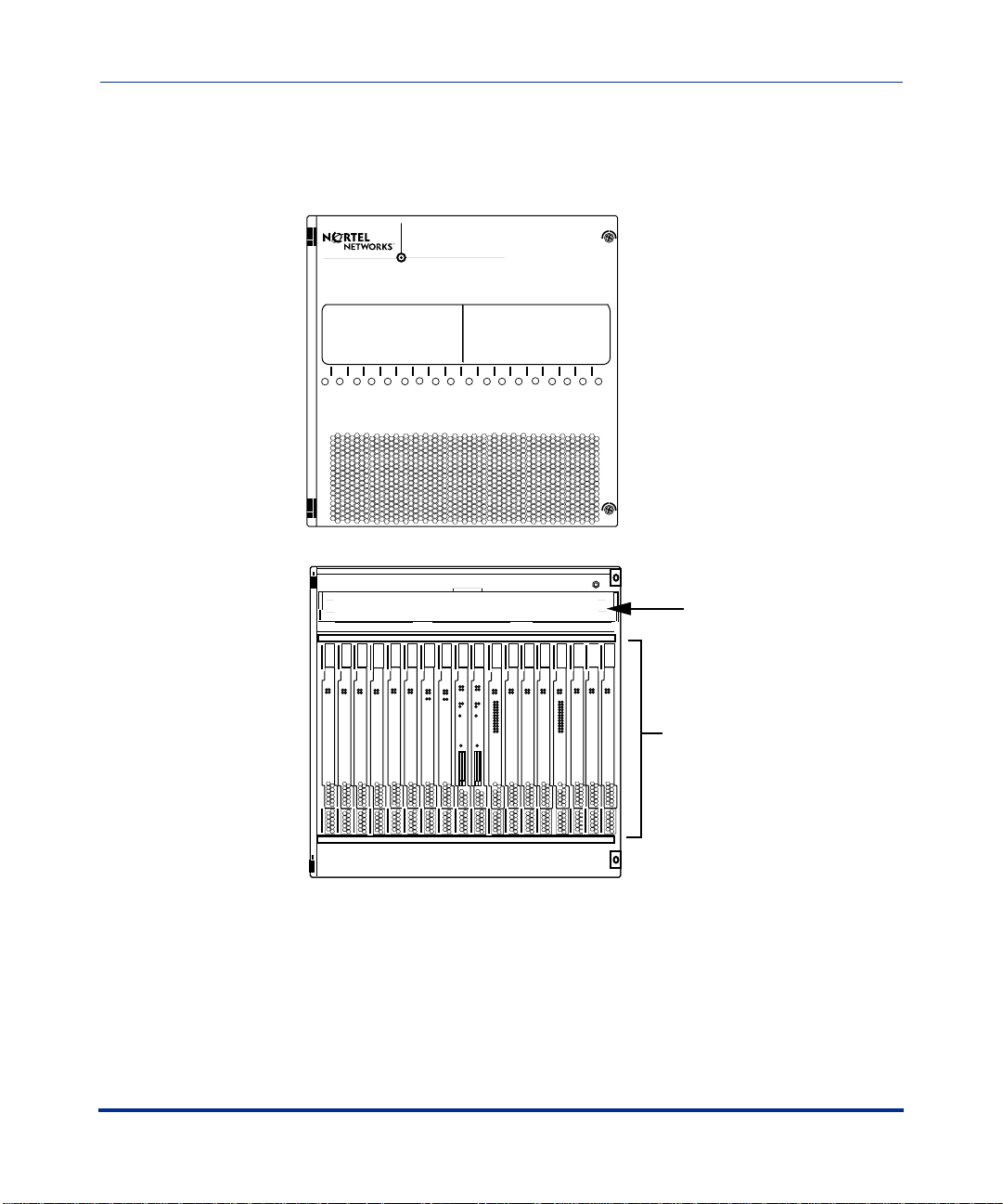
Front View of CVX 1800 Chassis
The following figure shows the front of the metal fascia CVX 1800 chassis.
CVX 1800
1 2 3 4 5 6 7 8 9 10 11 12 13 14 15 16 17 18
Do Not Block Air Inlets
Metal Fascia Ch assis Installation
CVX 1800 Chassis Overview
Door in closed position
1 2 3 4 5 6 7 8 9 10 11 12 13 14 15 16 17 18
FAN TRAY
Pull handle
Replacement during operation should
be completed quickly to avoid
system over temperature condition.
Remove screw
See documentation for recommendations.
Modem/ISDN
Power
Good
Failed
Redund
Modem/ISDN
Modem/ISDN
Modem/ISDN
Modem/ISDN
Power
Power
Failed
Good
Power
Good
Good
Power
Good
Failed
Redund
Failed
Redund
Redund
Failed
Redund
Slots 9 and 10 for
System Controller
only
Replace air filter regularly.
See documentation for recommendations.
System
System
Good
Good
Power
Power
DS1 X 12
Modem/ISDN
DS3 X 1
DS3 X 1
Power
Good
Power
Good
Power
Good
Failed
Redund
Failed
Redund
Failed
Redund
YEL RED
YEL RED
1
1
Modem/ISDN
Modem/ISDN
Power
Good
Failed
Redund
10/100 Enet
1
2
3
HSSI
1
Reset
PCMCIA
2
1
Power
Failed
Redund
Power
Good
Failed
Redund
Failed
Failed
Redund
YEL RED
10/100 Enet
1
1
2
2
3
3
4
5
HSSI
1
6
7
8
9
10
11
12
Reset
PCMCIA
2
1
ESD Strap Jack
Pull handle
Remove screw
DS1 X 12
Modem/ISDN
Modem/ISDN
Modem/ISDN
Power
Power
Good
Power
Good
Good
Power
Good
Failed
Failed
Redund
Failed
Redund
Redund
Failed
Redund
YEL RED
1
2
3
4
5
6
7
8
9
10
11
12
Door in open position
Fan module
Modem/ISDN
Power
Good
Good
Failed
Redund
Redund
System control cards (SCCs)
Modem access cards (MACs)
Digital access cards (DACs)
CVX-0093C
296-1011-200 Rel. 5.0, Doc. Rev. 08.01 1-3
CVX 1800 Hardware Installation Guide
CVX 1800 Chass is Ove rview
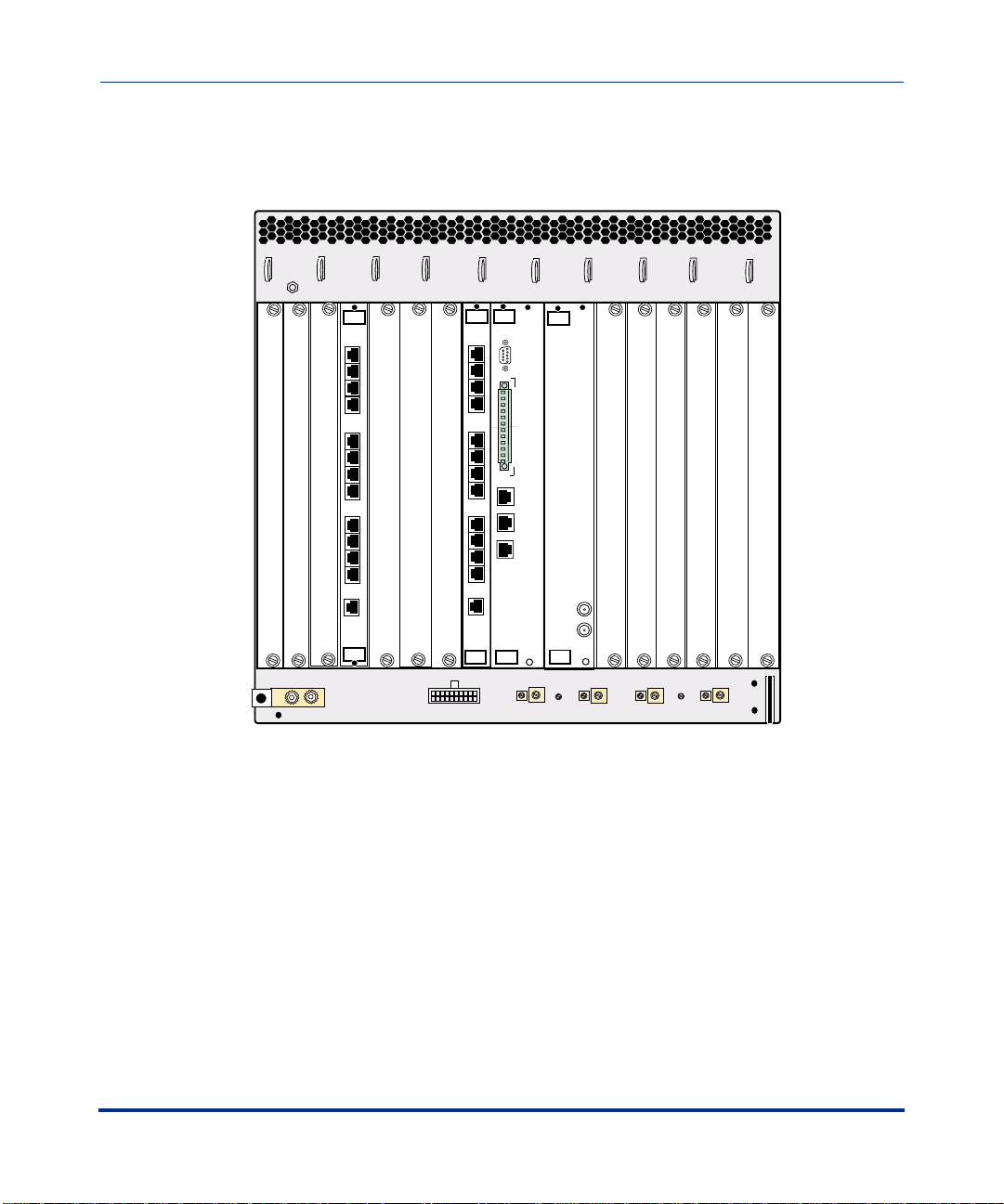
Rear View of CVX 1800 Chassis
The following figure shows the rear of the metal fascia CVX 1800 chassis.
ESD Strap Jack
18 17 16 15 14 13 12 11 10 9 8 7 6 5 4 3 2 1
DS1x12
1
4
5
8
9
12
Clock
DS1x12
Clock
System
1
Console
1
2
3
4
4
5
6
7
5
8
9
10
11
12
10/100 Enet
TX
1
8
RX
10/100 Enet
9
TX
2
RX
10/100 Enet
TX
3
RX
12
DS3
Redundant
Audible
Crit
Ret
Maj
Ret
Min
Ret
Crit
Ret
Maj
Ret
Min
Ret
Visual
Alarms
RX
TX
Line termination
modules (LTMs)
and filler panels
Frame
Ground
Frame grounding
Connect to CVX 1800
AC Front End Only
AC power connector
Connect to Fused 50 Amp Circuits
RTN
RTN
DC power connections
A
-48V
B
-48V
CVX-0092B
1-4 296-1011-200 Rel. 5.0, Doc. Rev. 08.01

Metal Fascia Ch assis Installation
Preparing the Site for the Installation
Preparing the Site for the Installation
Overview
Before you install the CVX 1800 chassis, you need to pr epa re you r site. Consider
the installation of the rack, tools and equipment needed, space requirements, and
weight. These issues are addressed in detail in this chapter.
Reference
For information about environmental requirements and power specifications, see
Appendix B, “Metal Fascia Chassis Technical Specifications and Procedures.”
296-1011-200 Rel. 5.0, Doc. Rev. 08.01 1-5
CVX 1800 Hardware Installation Guide
Mounting the CVX 1800 in a Rack
Mounting the CVX 1800 in a Rack
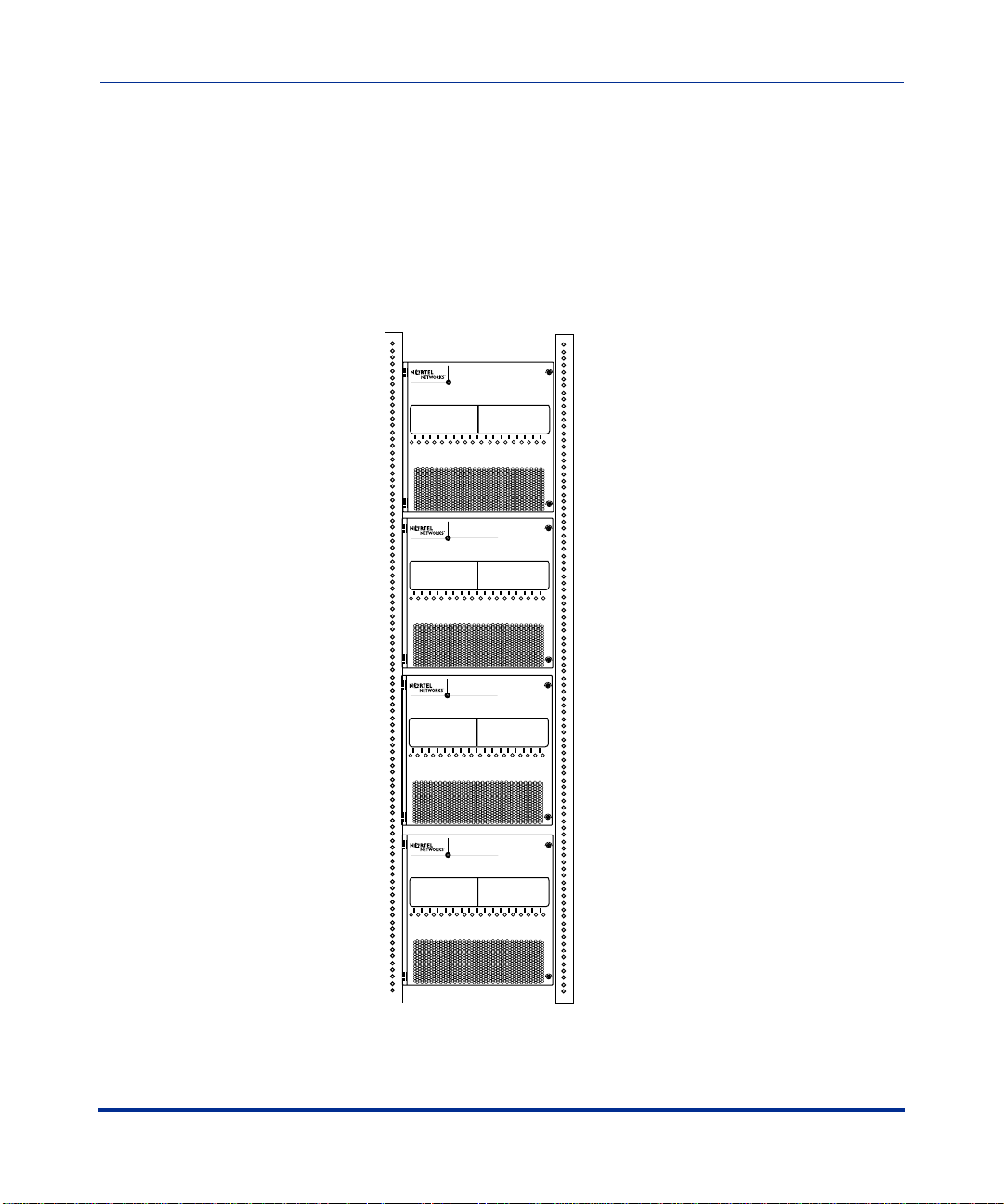
Rack Capacity
You can install four CVX 1800 switches in a standard Telco or Electronics
Industry Association (EIA) rack.
7 ft Telco rack
CVX 1800
Shelf 4
Shelf 3
Shelf 2
Shelf 1
1 2 3 4 5 6 7 8 9 10 11 12 13 14 15 16 17 18
Do Not Block Air Inlets
CVX 1800
1 2 3 4 5 6 7 8 9 10 11 12 13 14 15 16 17 18
Do Not Block Air Inlets
CVX 1800
1 2 3 4 5 6 7 8 9 10 11 12 13 14 15 16 17 18
Do Not Block Air Inlets
CVX 1800
1 2 3 4 5 6 7 8 9 10 11 12 13 14 15 16 17 18
Do Not Block Air Inlets
CVX-0112B
1-6 296-1011-200 Rel. 5.0, Doc. Rev. 08.01
 Loading...