

Page 1
NTP #:411-1333-923
Draft 01.03 November 2000
CTR 28-08 GHz MMIC
Quick Reference Guide
Product Overview
The CTR 28-08 MMIC (NTVG16BH) outdoor transceiver is a customer premise
transceiver designed to operate in various Receiver (Rx) and Transmitter (Tx)
frequency bands. It is a Nortel Networks Reunion product that operates in conjunction with base station p roducts, as well as customer premise products. It is
compatible with Reunion’s Release 1.2, 1.3 and 1.4 equipment.
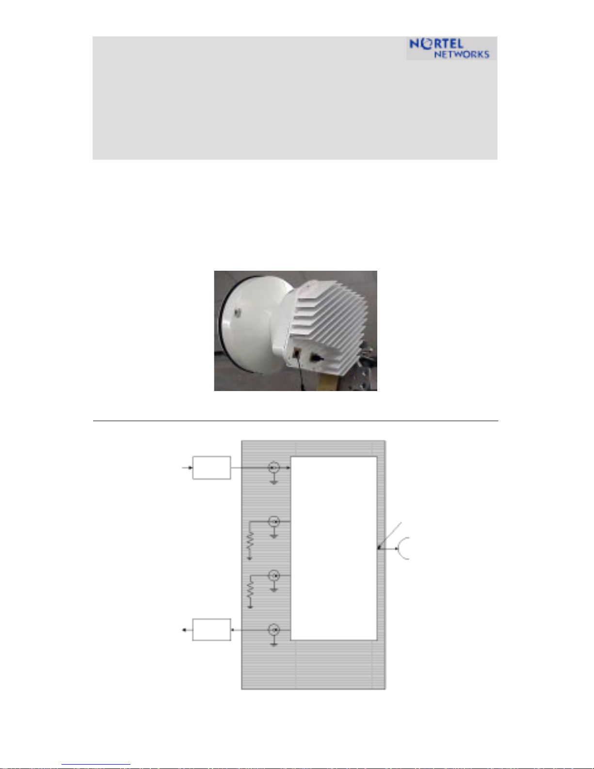
CTR 28M Transceiver
Figur e 1: CTR 28M Block Diagram
Tx IF/DC Inpu t
Lightning
Protector
Rx IF Outp ut
Lightning
Protector
Tx IF Input
Test Port
Rx IF
Output
Test Port
Transceiver
Radio
Tx RF Ou tpu t
Rx RF Input
Page 2

2
CTR 28-08 MMIC Specification
Table 1: CTR 28-08M Technical Specifications
TX IF Input RF Output
Frequency Range 28-08M
Output Level (P1 dB)
Output Level (IP3)
Input Impedance
Input/Output Connector
Input/Output VSWR
Gain (not including antenna)
Gain vs. Temperature
Gain Flatness
Frequency Stability
Noise Figure
Tx IF Test Port
500-650 MHz 27.85-28.00 GHz
≥23 dBm, -40° to +55° C
> +31 dBm
50 Ohms
N-Type Female N/A (integrated antenna)
1:93:1 maximum N/A
33 dB
±2.0 dB ( -40° to +55° C)
±2.0 dB over bandwidth
<±4 ppm, Over all Conditions
24.5 dB
Type SMA jack (F)
Antenna CTR
Frequency 27.5 - 31.3 GHz
Frequency band
Bore-sight Gain (Azimuth)
Polarity
Beam Width (azimuth)
Beam Width (elevation)
Flanges
Port-to-Port Isolation
Cross-Polarization Discrimination
Diameter
411-1333-923 Draft 01.03 November 2000
2731
37.4 ±1.4 dB
V/V or H/H determined mechanically on installation
2.6±TBD°, minimum
2.6±TBD°, minimum
WR-42
35 dB, minimum
> 30 dB
14" (35 cm)
Page 3

RX RF Input IF Output
Frequency Range 28-08M 27.50 - 27.65 GHz 150-300 MHz
3
Input/Output Connector
Output Impedance
Input/Output VSWR
Gain (not including antenna)
Gain Flatness
Gain Stability
Frequency Stability
Noise Figure
Rx IF Test Po rt
Power Requirements CTR
N/A (integrated antenna) N-Type Female
50 Ohms
N/A (integrated antenna) 1:93:1 maximum
28.0 ±1.0 dB
±2.0 dB over bandwidth
±2.0 dB over temperature
<±4 ppm
7.8 dB, -40° to +55° C
Type SMA jack (F)
Input Voltage ±48 VDC, 3A. max
diplexed with TX cable
Input Inrush Current
Input Power
Environmental CTR
4.5A max
54 Watts, maximum
Humidity 100% condensing
Altitude
Operating Wind Resistance
Operating Temperature
Storage Temperature Range
Solar Loading
Mechanical CTR
10,000 feet
50m/second on all surfaces
-40° to +55°C
-45° to +70°C (packaged)
ETS 300 019 class 4.1 1120W/m2, 50°C max.
Size (Length x Height x Width) 14" x 14" x 11" (35.6 x 35.6 x 27.9 cm)
Weight without brackets
25 lbs. (11.41 KG)
CTR 28-08 GHz MMIC Quick Reference Guide
Page 4

Converted Frequency Formula
Use the following formula to calculate the converted frequency:
TX:
RX:
ƒ
RF OUT
ƒ
IF OUT
(GHz) =
(GHz) =
ƒ
(GHz) + 27.35
ƒ
IF IN
(GHz) - 27.35
RF IN
Note: Electrostatic deposition powder coat, scratch free.
TM
Note: Vent holes are covered with a Goretex
patch.
Note: The transceiver mounts to a vertical pole of 2.5” to 4.5” outside diameter. It has a range of motion of 90°
over and -60° under horizo n. The bas es of
the antenna mount can rotate ±180°.
Technical Assistance Contact Information
In case additional technical assistance is required, or the transceiver unit is
damaged upon receipt, contact Nortel Networks.
Nortel Networks Broadband Wireless Access (BWA) provides 24-hour customer
service and technical support to ensure your service operation is trouble-free.
If you have questions or need technical support, contact Nortel Networks
Broadband Wireless Access at the following telephone numbers:
• In the USA and Canada, call 972-BWA-ETAS/972-292-3827
Information is subject to change witho ut notic e .
Nortel reserves the right to make changes in
design or components as progress in engineering
and manufacturing may warrant.
© 2000 Northern Telecom Ltd.
 Loading...