

Page 1

Nortel Communication Server 1000/Communication Server 2100
Solution/Meridian SL-100
Nortel Integrated Conference
Bridge: Service Implementation
Fundamentals
NN43001-558/555-4001-135
.
Page 2

Document status: Standard
Document version: 01.02
Document date: 20 June 2007
Copyright © 2007, Nortel Networks
All Rights Reserved.
Sourced in Canada.
The information in this document is subject to change without notice. The statements, configurations, technical
data, and recommendations in this document are believed to be accurate and reliable, but are presented without
express or implied warranty. Users must take full responsibility for their applications of any products specified in this
document. The information in this document is proprietary to Nortel Networks.
Nortel, the Nortel Logo, the Globemark, SL-1, Meridian 1, and Succession are trademarks of Nortel Networks.
All other trademarks are the property of their respective owners.
Page 3

3
Revision History
June 2007
Standard 01.02. This document is up-issued to support Communication
Server 1000 Release 5.0.
September 2005
Standard 01.01, ICB Release 4. Updated NTP to include workaround
regarding IP changes in Dual Card Configuration mode that fail to allow
reassignment of IP.
Nortel Communication Server 1000/Communication Server 2100 Solution/Meridian SL-100
Nortel Integrated Conference Bridge: Service Implementation Fundamentals
NN43001-558/555-4001-135 01.02 Standard
ICB Release 4 20 June 2007
Copyright © 2007, Nortel Networks
.
Page 4

4 Revision History
Nortel Communication Server 1000/Communication Server 2100 Solution/Meridian SL-100
Nortel Integrated Conference Bridge: Service Implementation Fundamentals
NN43001-558/555-4001-135 01.02 Standard
ICB Release 4 20 June 2007
Copyright © 2007, Nortel Networks
.
Page 5

5
Contents
How to get help 11
Getting Help from the Nortel Web site 11
Getting Help over the phone from a Nortel Solutions Center 11
Getting Help through a Nortel distributor or reseller 12
Introduction 13
Product description 17
Purpose 17
ICB description 17
Conference administration 17
System overview 19
ICB conference feature summary 19
Hardware overview 21
ICB hardware design characteristics 22
External equipment 26
ICB operation 26
Join the conference using the direct meeting access method 28
Join the conference using the single DN access method 29
Expand the conference 32
End the conference 32
Engineering guidelines 35
Purpose 35
System requirements 35
Software 35
Hardware 36
System capacity 37
Physical Capacity 37
System compatibility 37
Meridian 1 and Option 11 37
CS 1000 38
CS 2100/Meridian SL-100 system compatibility 38
Automatic call distribution resource allocation 38
LAN configuration 39
Nortel Communication Server 1000/Communication Server 2100 Solution/Meridian SL-100
Nortel Integrated Conference Bridge: Service Implementation Fundamentals
NN43001-558/555-4001-135 01.02 Standard
ICB Release 4 20 June 2007
Copyright © 2007, Nortel Networks
.
Page 6

6 Contents
Global internet access 39
LAN/intranet access only 41
Notes 43
Summary of LAN installation information 44
Installation and configuration 45
Purpose 45
Getting started 45
Unpack and inspect the equipment 46
Take inventory 46
Verify IPE Slot(s) 46
Determine the access method 47
Installing the NTCW84JA I/O Panel Filter Connector for a Large System 47
CS 1000 configuration 47
Summary 47
Assign ACD DNs 48
Define Phantom TN blocks 48
Configure DNs for a dual-card conference 52
Assign CDR data 54
CS 2100/Meridian SL-100 configuration 55
Single-card configuration 55
Dual-card configuration 60
ICB installation and configuration procedures 65
ICB Installation Wizard 74
Overview 74
Step 1 - Basic Card Settings 75
Step 2 - Access Numbers 78
Step 3 - Define First User 80
Step 4 - Dual Card Meetings 80
Browser user interface 83
Purpose 83
Overview 83
User types 84
Log into the BUI 84
Login password change 86
Customize the BUI home page and title bar 87
Fixed title frame 88
Scheduling BUI 89
Meetings List window 90
Scheduling window 93
Chairperson operations 103
Meeting Control window 103
Administration BUI 110
Introduction 110
Nortel Communication Server 1000/Communication Server 2100 Solution/Meridian SL-100
Nortel Integrated Conference Bridge: Service Implementation Fundamentals
NN43001-558/555-4001-135 01.02 Standard
ICB Release 4 20 June 2007
Copyright © 2007, Nortel Networks
.
Page 7

Contents 7
ICB Dashboard 111
Settings 113
Default conference 115
Volume Level 116
E-mail template 117
Customize greetings 118
Company images upload 121
Upgrades 122
Users 122
Call-out Groups 128
Permanent Conferences 135
Telephone user interface 141
Purpose 141
Overview 141
Active conference 141
Scheduling and recording features 141
TUI operation during an active conference 142
Chairperson features 142
Features available to all participants 149
Conferee features 150
TUI services 151
Schedule a conference 152
Record a brandline greeting 153
Record a conference-specific greeting 154
Microsoft Outlook GUI 157
Purpose 157
Overview 157
Publishing the form in Microsoft Outlook 158
Removing the ICB files from the Personal Forms Library 164
Login to the ICB card using Microsoft Outlook 166
Scheduling a new conference 167
Scheduling window 167
Setting a delegate user for Microsoft Outlook Calendar 174
Maintenance 175
Purpose 175
Maintenance overview 175
Problem solving 177
Updating the Microsoft Outlook GUI ICB form 177
Diagnostic tools 180
ICB status LED indicator 181
Power Up Self-test 181
Signaling Tests 182
Nortel Communication Server 1000/Communication Server 2100 Solution/Meridian SL-100
Nortel Integrated Conference Bridge: Service Implementation Fundamentals
NN43001-558/555-4001-135 01.02 Standard
ICB Release 4 20 June 2007
Copyright © 2007, Nortel Networks
.
Page 8

8 Contents
Sanity monitoring 182
Diagnostic commands 182
TCP/IP connectivity test 184
CLI command summary 184
Using CLI commands 184
ICB CLI commands 185
ICB fault isolation and correction 188
Card replacement 189
Error message handling 190
Error messages format 190
Error message procedures 191
Advanced troubleshooting 194
Backup and restore procedures 194
Backup 195
Restore 200
Backup and restore process log 201
Reports 203
Purpose 203
Overview 203
BUI Report Viewer 204
Short Connection Report 205
BUI Short Connection Report 205
CLI Short Connection Report 206
Meetings Log Report 206
BUI Meetings Log Report 206
CLI Meetings Log Report 207
Overbooking Report 208
BUI Overbooking Report 208
Overbooking Report (.CSV) 209
Billing Report 210
Introduction 210
BUI Billing Report 211
Billing Report (.CSV) 212
CS 1000 Call Detail Recording 216
CDR example scenarios 217
Maintenance (Error) Report 218
BUI Maintenance (Error) Report 218
CLI Maintenance (Error) Report 218
Upgrades 221
Purpose 221
Overview 221
Keycode security 223
Planning for an upgrade 224
Nortel Communication Server 1000/Communication Server 2100 Solution/Meridian SL-100
Nortel Integrated Conference Bridge: Service Implementation Fundamentals
NN43001-558/555-4001-135 01.02 Standard
ICB Release 4 20 June 2007
Copyright © 2007, Nortel Networks
.
Page 9

Contents 9
Managing the user community during an upgrade 224
Upgrade procedures 225
MICB Release 2 or MICB Release 3 card upgrade 225
Port Upgrade 226
Firmware Upgrade 228
Upgrade to the single DN access method 230
Upgrade from a stand-alone to a dual-card ICB 231
Appendix A Password security 235
Purpose 235
Access permissions 235
Unsuccessful login attempt handling 237
Password parameters summary 238
Reset passwords 239
CLI Password Editor editing session 241
Application Protocol Port Numbers 243
Appendix B Product integrity 245
Environmental specifications 245
Regulatory standards 246
Safety 246
Electro-magnetic compatibility (EMC) 246
MTBF 247
List of terms 249
Procedures
Procedure 1 Prepare for the installation 46
Procedure 2 Configure a single-card conference 56
Procedure 3 Configure a dual-card conference 64
Procedure 4 Install the Ethernet Adapter card 66
Procedure 5 Access the ICB directly 68
Procedure 6 Access the ICB remotely using a modem 69
Procedure 7 Access the ICB remotely using a LAN hub 69
Procedure 8 Access the ICB directly - Option 11C or CS 1000 70
Procedure 9 Access the ICB remotely using a modem - Option 11C or CS
1000 71
Procedure 10 Access the ICB remotely using a LAN hub - Option 11C or CS
1000 71
Procedure 11 Install ICB cards 72
Procedure 12 Set up CLI access from the maintenance terminal 72
Procedure 13 Configure initial card parameters using the CLI 73
Procedure 14 Access the administration BUI 74
Procedure 15 Login to the BUI 85
Procedure 16 Change your login password 87
Procedure 17 Replace the brandline greeting 119
Procedure 18 Use a customized image 121
Procedure 19 Adjust the conference audio volume 149
Procedure 20 Acquire/release chairperson control 150
Nortel Communication Server 1000/Communication Server 2100 Solution/Meridian SL-100
Nortel Integrated Conference Bridge: Service Implementation Fundamentals
NN43001-558/555-4001-135 01.02 Standard
ICB Release 4 20 June 2007
Copyright © 2007, Nortel Networks
.
Page 10

10 Contents
Procedure 21 Use the TUI to schedule a conference 152
Procedure 22 Use a brandline greeting 153
Procedure 23 Configure a conference-specific greeting 154
Procedure 24 ICB Administrator to get the ICB form 158
Procedure 25 Microsoft Outlook Administrator to publish the ICB files to the
Organizational Forms Library 160
Procedure 26 Publishing the ICB form in Microsoft Outlook by each Microsoft
Outlook user 161
Procedure 27 Select the ICB form as the default form in Microsoft
Outlook 163
Procedure 28 Resetting the default Calendar form for Microsoft Outlook 164
Procedure 29 Removing the ICB files from the Personal Forms Library (way
1) 165
Procedure 30 Removing the ICB files from the Personal Forms Library (way
2) 165
Procedure 31 Log into the ICB card using Microsoft Outlook 166
Procedure 32 Clearing the Microsoft Outlook forms Cache 177
Procedure 33 Deleting the forms cache file manually 178
Procedure 34 Upgrading the ICB form in the Organizational Forms
Library 179
Procedure 35 Upgrading the ICB form in the Personal Forms Library 180
Procedure 36 Replace a card 189
Procedure 37 Access the on-line error message analysis tool 191
Procedure 38 Retrieve the entire error message file to a PC 192
Procedure 39 Configure error message filtering 193
Procedure 40 Restore the database from the secondary PCMCIA 200
Procedure 41 Restore the database from a backed up ZIP file 201
Procedure 42 Displaying reports 204
Procedure 43 MICB Release 2 or MICB Release 3 card upgrade 225
Procedure 44 Upgrade ports from the administrator ICB Dashboard 227
Procedure 45 Upgrade the ICB firmware version 228
Procedure 46 Firmware upgrade from ICB card upper socket 229
Procedure 47 Firmware upgrade using FTP 229
Procedure 48 Upgrade to single DN access 230
Procedure 49 Stand-alone card to secondary card 231
Procedure 50 Stand-alone card to primary card 232
Procedure 51 Meridian switch configuration changes 233
Procedure 52 Unsuccessful login operation 237
Procedure 53 Reset forgotten passwords 239
Procedure 54 Use the second-level CLI edit password command 240
Nortel Communication Server 1000/Communication Server 2100 Solution/Meridian SL-100
Nortel Integrated Conference Bridge: Service Implementation Fundamentals
NN43001-558/555-4001-135 01.02 Standard
ICB Release 4 20 June 2007
Copyright © 2007, Nortel Networks
.
Page 11

11
How to get help
Getting Help from the Nortel Web site
The best source of support for Nortel products is the Nortel Support Web
site:
h
ttp://www.nortel.com/support
This site enables customers to:
• download software and related tools
•
download technical documents, release notes, and product bulletins
•
sign up for automatic notification of new software and documentation
• search the Support Web site and Nortel Knowledge Base
•
open and manage technical support cases
Getting Help over the phone from a Nortel Solutions Center
If you have a Nortel support contract and cannot find the information you
require on the Nortel Support Web site, you can get help over the phone
from a Nortel Solutions Center.
In North America, call 1-800-4NORTEL (1-800-466-7835).
Outside North America, go to the Web site below and look up the phone
number that applies in your region:
h
ttp://www.nortel.com/callus
When you speak to the phone agent, you can reference an Express Routing
Code (ERC) to more quickly route your call to the appropriate support
specialist. To locate the ERC for your product or service, go to:
h
ttp://www.nortel.com/erc
Nortel Communication Server 1000/Communication Server 2100 Solution/Meridian SL-100
Nortel Integrated Conference Bridge: Service Implementation Fundamentals
NN43001-558/555-4001-135 01.02 Standard
ICB Release 4 20 June 2007
Copyright © 2007, Nortel Networks
.
Page 12

12 How to get help
Getting Help through a Nortel distributor or reseller
If you purchased a service contract for your Nortel product from a distributor
or authorized reseller, you can contact the technical support staff for that
distributor or reseller.
Nortel Communication Server 1000/Communication Server 2100 Solution/Meridian SL-100
Nortel Integrated Conference Bridge: Service Implementation Fundamentals
NN43001-558/555-4001-135 01.02 Standard
ICB Release 4 20 June 2007
Copyright © 2007, Nortel Networks
.
Page 13

13
Introduction
Purpose and audience
This document instructs system administrators and installers how to install,
configure, operate, and maintain the Nortel Networks Integrated Conference
Bridge as a part of the overall Meridian system. In this guide, Meridian
system refers to either the Meridian 1, Nortel Networks Communication
Server 1000, or the Communication Server 2100/Meridian SL-100 switch.
The Integrated Conference Bridge (ICB) card allows you to schedule and
configure multiple simultaneous conferences.
You can install the ICB card in either the Meridian 1, Communication Server
1000 (CS 1000), or CS 2100/Meridian SL-100. In the majority of places
the ICB operates the same way regardless of the system in which you
install it. When the information differs between the systems, this guide
contains separate sections for the Meridian 1 and CS 1000, and the CS
2100/Meridian SL-100 (for example, configuration information).
Structure
This document contains the following sections:
•
"Product description" (page 17) - describes how the ICB operates and
the conference features it provides, as well as the card hardware and
software characteristics.
•
"Engineering guidelines" (page 35) - describes ICB system resource
allocation, and software and hardware requirements.
•
"Installation and configuration" (page 45) - describes how to prepare
the system for installation, install the ICB card, connect the ICB to the
administration terminal, and configure the ICB. This chapter contains
separate configuration sections for the Meridian 1 and CS 1000, and the
CS 2100/Meridian SL-100.
•
"Browser user interface" (page 83) - describes how to use the browser
user interface (BUI), a web-based server, for conference administration
and scheduling, as well as user administration and maintenance of the
ICB.
Nortel Communication Server 1000/Communication Server 2100 Solution/Meridian SL-100
Nortel Integrated Conference Bridge: Service Implementation Fundamentals
NN43001-558/555-4001-135 01.02 Standard
ICB Release 4 20 June 2007
Copyright © 2007, Nortel Networks
.
Page 14
14 Introduction
•
"Telephone user interface" (page 141) - describes how to use the
telephone user interface (TUI) for simple conference reservation, as well
as lists commands available to participants during an active conference.
•
"Microsoft Outlook GUI" (page 157) - describes how to use the Microsoft
Outlook GUI for audio conference reservations.
• "Maintenance" (page 175) - shows how to perform maintenance and
troubleshooting operations. Includes a description of the Command
Line Interface (CLI).
•
"Reports" (page 203) - introduces the reports that the ICB can generate
and describes billing.
•
"Upgrades" (page 221) - provides procedures for upgrading to ICB
Release 4 from previous releases.
•
Appendix "Password security" (page 235) - describes ICB password
protection and access restrictions.
•
Appendix "Product integrity" (page 245) - provides environmental
specifications and shows regulatory standards.
•
"List of terms" (page 249) - describes the terms used in this guide.
How to check the version and issue of this document
The version and issue of the document are indicated by numbers (for
example, 00.03).
The first two digits indicate the version. The version number increases
each time the document is updated to support a new software release.
For example, the first release of a document is 01.01. In the next software
release cycle, the first release of the same document is 02.01.
The second two digits indicate the issue. The issue number increases each
time the document is revised, but re-released in the same software release
cycle. For example, the second release of a document in the same software
release cycle is 01.02.
ATTENTION
To determine whether you have the latest version of this document and how
documentation for your product is organized, check the release information in the
Meridian 1 Library Navigator or the Meridian SL-100 Master Index of Publications.
References in this document
Nortel Networks Communication Server 1000
If you are installing the ICB in a Communication Server 1000, see the
following documents for additional information:
•
Large System Management, 553-3021-500
Nortel Communication Server 1000/Communication Server 2100 Solution/Meridian SL-100
Nortel Integrated Conference Bridge: Service Implementation Fundamentals
NN43001-558/555-4001-135 01.02 Standard
ICB Release 4 20 June 2007
Copyright © 2007, Nortel Networks
.
Page 15

References in this document 15
•
Large System Planning, 553-3021-120
•
Transmission Parameters, 553-3001-182
•
Call Detail Recording, 553-3001-100
•
Input/Output Administration, 553-3001-311
•
Features and Services, 553-3001-306
Nortel Networks Communication Server 1000S
If you are installing the ICB in a Communication Server 1000S, see the
following documents for additional information:
•
Planning and Installation Guide, 553-3031-120
• Installation and Configuration Guide, 553-3031-210
•
Maintenance Guide, 553-3031-500
CS 2100 or Meridian SL-100
If you are installing the ICB in a CS 2100/Meridian SL-100, see the following
documents for additional information:
•
IPE Reference Manual, 555-4001-129
•
Alarm Clearing Procedures, 555-4031-543
•
Routine Maintenance Procedures, 555-4031-546
•
Card Replacement Procedures, 555-4031-547
•
Log Report Reference Manual, 555-4031-840
End user documentation
The following documents apply to all platforms:
•
Nortel Networks Integrated Conference Bridge Release 4 User Guide,
P0989944 - shows end user how to schedule and manage a conference
using either the Telephone User Interface or the Browser User Interface.
•
Nortel Networks Integrated Conference Bridge Release 4 Quick
Reference Card, P0989945 - provides a list of Telephone User Interface
commands; comes in a package of 20.
Nortel Communication Server 1000/Communication Server 2100 Solution/Meridian SL-100
Nortel Integrated Conference Bridge: Service Implementation Fundamentals
NN43001-558/555-4001-135 01.02 Standard
ICB Release 4 20 June 2007
Copyright © 2007, Nortel Networks
.
Page 16

16 Introduction
Nortel Communication Server 1000/Communication Server 2100 Solution/Meridian SL-100
Nortel Integrated Conference Bridge: Service Implementation Fundamentals
NN43001-558/555-4001-135 01.02 Standard
ICB Release 4 20 June 2007
Copyright © 2007, Nortel Networks
.
Page 17

17
Product description
Purpose
This chapter describes the functional and physical characteristics of the
Nortel Networks Integrated Conference Bridge Release 4. Technicians can
install the Integrated Conference Bridge (ICB) card in either a Meridian 1,
Nortel Networks Communication Server 1000, Meridian SL-100, or Nortel
Networks Communication Server 2100. This guide uses the term "Meridian
system" to refer to either the Meridian 1, Meridian SL-100, Communication
Server 1000 (CS 1000), or CS 2100.
The chapter contains the following sections:
•
"ICB description" (page 17) - describes the ICB card and the role it plays
in conference calls. Summarizes ICB features and services.
•
"Hardware overview" (page 21) - describes the hardware components
of the ICB system.
•
"ICB operation" (page 26) - shows how ICB conferences operate.
ICB description
Conference administration
The ICB card allows users to schedule and administer multiple simultaneous
conferences. Schedule conferences based on time-of-day, duration of
each conference, and number of individuals (conferees) participating in, or
ports allocated, for each conference. Schedule a conference using one
of the following:
•
"Browser user interface" (page 83) - point and click web-page application
•
"Telephone user interface" (page 141) - telephone keypad entries
•
"Microsoft Outlook GUI" (page 157) - Microsoft Office Outlook graphical
user interface (GUI)
•
Ad hoc meeting - audio conference created now
Nortel Communication Server 1000/Communication Server 2100 Solution/Meridian SL-100
Nortel Integrated Conference Bridge: Service Implementation Fundamentals
NN43001-558/555-4001-135 01.02 Standard
ICB Release 4 20 June 2007
Copyright © 2007, Nortel Networks
.
Page 18

18 Product description
The ICB card provides announcements and tones that relate to specific
events during conferences. These events include the following:
•
advising the chairperson and conferees of the status of the conference
connection
•
indicating when a conferee joins or leaves the conference, and
•
warning the chairperson and the conferees when the conference is
about to expire.
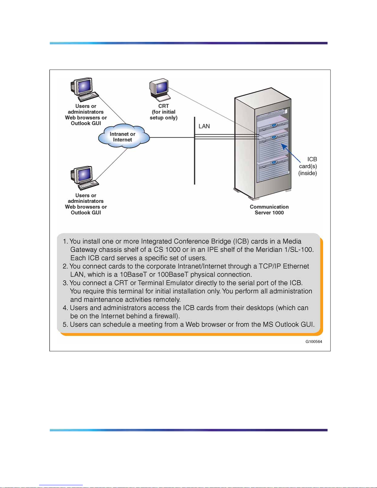
Technicians can install multiple ICB cards into:
•
a Media Gateway chassis shelf for a CS 1000
•
an Intelligent Peripheral Equipment (IPE) shelf for a Meridian 1/CS 1000
•
an Option 11 shelf
•
an IPE shelf for a CS 2100/Meridian SL-100
Each ICB card can operate independently, providing up to 32 ports for
a single conference. The ICB card can support up to ten simultaneous,
separate conferences.
When users establish a single-card conference, they use the 32 ports on
the card. If two conferences are held at the same time, they need to share
the 32 ports. For example, if one user sets up a 10-port conference, the
other can set up a 22-port conference.
Technicians can connect two ICB cards to provide up to 62 ports for a single
conference. In dual mode, there can be only one dual-card meeting per
pair of cards. The user database and access numbers are not shared in a
dual-card configuration. There is a separate access number required for
a dual-card meeting.
The ICB supports several simultaneous conferences. The number of
conferences depends on the number of ICB ports available and the number
of participants (conferees) in each conference. Each ICB card supports
the following:
•
maximum number of participants as follows:
— single-card: 32 participants
— dual-card: 62 participants (unless Chairperson Control over a
Dual-card Meeting is activated, in which case it is 60 participants)
•
any number of conferences (up to 10) with one or more participants
in each conference
Nortel Communication Server 1000/Communication Server 2100 Solution/Meridian SL-100
Nortel Integrated Conference Bridge: Service Implementation Fundamentals
NN43001-558/555-4001-135 01.02 Standard
ICB Release 4 20 June 2007
Copyright © 2007, Nortel Networks
.
Page 19

ICB description 19
The ICB communicates with the system software by emulating a digital
line card (XDLC), which allows existing software to control the operation of
the ICB. Configure each ICB port as an Automatic Call Distribution (ACD)
M2616 digital telephone set.
System overview
The ICB comes as a single card, or a pair of cards if additional ports are
required to support a dual-card meeting. Each card stands alone, even in
the dual-card configuration. For dual-card meetings, the primary card uses
ports on the secondary card. The following rules apply:
•
Each card (that is, the primary and secondary) has its own set of users.
There is no "common list" for both cards.
• To schedule a conference, the user logs into the card in which their
account is defined. If the user has two accounts, one on each card,
they must try each card separately to find available resources for the
conference. There is no automatic pooling between cards.
•
A user, super-user, or executive-user can have accounts on many cards
at a company (that is, a customer can have one person who administers
multiple bridges for their company).
•
Dual-card conferences can only be scheduled by users on the primary
card.
ICB conference feature summary
The ICB:
•
Allows volume control by conference participants.
•
Offers customized conference-specific greetings.
•
Enables users to acquire and release chairperson control while in a
conference.
•
Delivers pre-meeting and post-meeting participants notifications.
•
Allows one chairperson per conference.
• Offers optional chairperson control on the secondary card of a dual-card
conference.
•
Provides for one or more permanent bridge configurations.
•
Supports multiple conferences simultaneously.
•
Provides chairperson commands during an active conference.
•
Provides conferee commands during an active conference.
•
Allows conference extension beyond the scheduled time.
•
Issues a 10-minute warning, before the conference termination. Also
issues a second warning, two minutes before conference termination.
Nortel Communication Server 1000/Communication Server 2100 Solution/Meridian SL-100
Nortel Integrated Conference Bridge: Service Implementation Fundamentals
NN43001-558/555-4001-135 01.02 Standard
ICB Release 4 20 June 2007
Copyright © 2007, Nortel Networks
.
Page 20

20 Product description
•
Supports dial-in and voice prompts for multiple languages including:
N.A. English, Latin-American Spanish, French, Brazilian Portuguese,
L.A. Spanish, Japanese, Korean, U.K. English, German, Chinese,
Dutch, Canadian-French, Swedish, and Italian. Refer to the Sales and
Marketing Bulletin for the latest supported languages.
•
Provides conference password security,requiring the chairperson and/or
the conferees to enter a Dual-Tone Multifrequency (DTMF) password
before entering the conference.
•
Automatically starts and terminates conferences based on reservations
scheduled in advance.
•
Provides Group Call with smart retry.
• Provides the ability to reserve a port in each conference for the
chairperson.
•
Provides "Block scheduling" for recurrent conferences, up to one year in
advance and up to 52 iterations of recurrent conferences.
•
Offers an over-booking option, enabling the administrator to allocate up
to 125% of port resources (based on the idea that most conferences are
scheduled with more ports than are required).
•
Provides an emergency bridge option, which creates a permanent
bridge that automatically dials a pre-determined list of DNs when
someone dials the emergency bridge DN. The emergency bridge does
not support the dual-card configuration.
•
Provides automatic conference expansion, allowing additional conferees
to join the conference. For the expansion to work, the ports hosting the
additional conferees must be both unassigned and available.
•
Provides entry and exit indications - provides four options to indicate the
entry and exit of a conference participant:
— entry by name, exit by name
— entry by name, exit by tone
— entry by tone, exit by tone
— silent entry and exit
•
Allows the first conferee joining the conference to turn off and turn on
conference music.
•
Controls access to the conference in progress by monitoring the
maximum number of scheduled attendees at each conference.
•
Manages time and date for scheduled conferences and reserves ports
for each conference.
Nortel Communication Server 1000/Communication Server 2100 Solution/Meridian SL-100
Nortel Integrated Conference Bridge: Service Implementation Fundamentals
NN43001-558/555-4001-135 01.02 Standard
ICB Release 4 20 June 2007
Copyright © 2007, Nortel Networks
.
Page 21

Hardware overview 21
•
Provides recorded announcements to conferees who attempt to enter a
meeting too early or after a meeting has ended.
•
Issues audible responses to conferees based on the conference activity.
•
Allows recording of a brand line (custom) greeting to replace the
standard greeting.
•
Provides a scheduling display that indicates meeting reference number
and whether a custom greeting has been created.
•
Provides scheduling receipts e-mailed to users (receipt includes the
direct meeting access DN or the single DN access DN).
•
Provides for Microsoft Outlook integration using the calendar to schedule
meetings.
•
Provides a second warning tone before ending the conference.
•
Allows users to copy a conference.
•
Allows the chairperson control of the conferee volume.
•
Provides current speaker indication.
•
Allows for questions and voting display.
•
Provides for default conference settings.
•
Allows users in the ICB card to access audio conference scheduling
in Microsoft Outlook.
•
Supports 500 users per card.
•
Provides for up to 52 recurring conferences.
•
Allows the administrator to define a time zone.
•
Offers a toll-free prefix in the e-mail notification.
•
Provides separate user, chairperson, and administrator context help.
•
Provides enhancements to the billing report.
Hardware overview
Figure 1 "ICB system composition" (page 22) shows ICB system
composition.
Nortel Communication Server 1000/Communication Server 2100 Solution/Meridian SL-100
Nortel Integrated Conference Bridge: Service Implementation Fundamentals
NN43001-558/555-4001-135 01.02 Standard
ICB Release 4 20 June 2007
Copyright © 2007, Nortel Networks
.
Page 22
22 Product description
Figure 1
ICB system composition
ICB hardware design characteristics
Each ICB card occupies one slot in a Media Gateway chassis slot (CS
1000) or an IPE shelf (Meridian 1/CS 1000/CS 2100/SL-100). ICB Release
4 is based on a new hardware platform. The ICB card has the following
hardware interface characteristics:
•
uses the microprocessor unit (MPU) based on the 50MHz MPC 860P
Power Quad Integrated Communications Controller
Nortel Communication Server 1000/Communication Server 2100 Solution/Meridian SL-100
Nortel Integrated Conference Bridge: Service Implementation Fundamentals
NN43001-558/555-4001-135 01.02 Standard
ICB Release 4 20 June 2007
Copyright © 2007, Nortel Networks
.
Page 23

Hardware overview 23
•
uses standard interface buses and personal computer memory card
international association (PCMCIA) cards and handles files that are
compatible with MS-DOS operating system on the PCMCIA storage
device and formatted with fat 16 file system. The fat 32 file system is
not supported.
•
uses 4MB flash memory for boot purposes
•
accesses all 32 DS-30X voice/signaling timeslots
•
provides echo cancelling and volume control
•
users 128 KB SRAM memory for saving trap data during resets
•
emulates an M2616 digital telephone set on each ICB port
•
supports Card-LAN interfaces
•
performs X12 signaling protocol messages for input/output
•
uses digital signal processor (DSP) for conferencing and DTMF detection
•
provides the drivers for the new hardware through the MPU firmware
•
The DSP firmware:
— Provides DTMF tone detection.
— Provides for A-law and u-law conversion.
— Provides the functionality for the conference bridge.
— Downloads the code from the MPU.
— Communicates with the MPU.
— Analyzes the loudness off all received signals continuously and
selects the two loudest signals to be the active speakers.
— Handles two-way conversation in conferences with three to 62
conferees.
— Normalizes the pulse code modulation (PCM) input samples.
— Provides gain control on all output samples.
— Provides software upgrades using a PCMCIA Flash card.
•
provides self-tests of internal hardware components and allows card
monitoring and maintenance through the maintenance port; provides
enable/disable capabilities similar to existing Meridian cards
•
provides one RS-232 serial port for administration and maintenance
access
•
provides enhanced Call Detail Recording (CDR - Meridian 1 only) and
billing options
•
provides an optional Ethernet interface over a Maintenance interface
Nortel Communication Server 1000/Communication Server 2100 Solution/Meridian SL-100
Nortel Integrated Conference Bridge: Service Implementation Fundamentals
NN43001-558/555-4001-135 01.02 Standard
ICB Release 4 20 June 2007
Copyright © 2007, Nortel Networks
.
Page 24
24 Product description
•
provides a Command Line Interface (CLI) accessible by direct
connection, modem, telnet, or BUI emulation for performing OA&M
functions
•
enables the reservation of one port on each card for TUI-only interaction
• provides an embedded web-based server
•
provides a customized ICB BUI login window
•
offers automatic backup. Backup configurations can be e-mailed to a
predefined e-mail address
Table 1 "ICB hardware list" (page 24) describes each hardware component
of the ICB application. These components connect the ICB to the local or
remote maintenance terminal.
Table 1
ICB hardware list
Component
Description
NT5D51BC or
higher ICB card
An IPE card that provides bridge and conference scheduling for up to 10
simultaneous conferences.
NT5D62FA or later
PCMCIA hard drive
card
This PCMCIA card contains the ICB software and configuration. Install the
PCMCIA card in the lower PCMCIA drive.
NT5D52 Ethernet
Adapter card
Install this adapter card to provide Ethernet connection for the ICB.
Note 1: NT5D52BC for CS 1000, CS 1000M, Meridian Option 11C, and
Meridian SL-100.
Note 2: NT5D52CA is used for Meridian Options 51-81C.
Note: Caution - You may need the NTCW84JA I/O Panel Filter
Connector for a large system. See "Installing the NTCW84JA I/O Panel
Filter Connector for a Large System" (page 47) for more information.
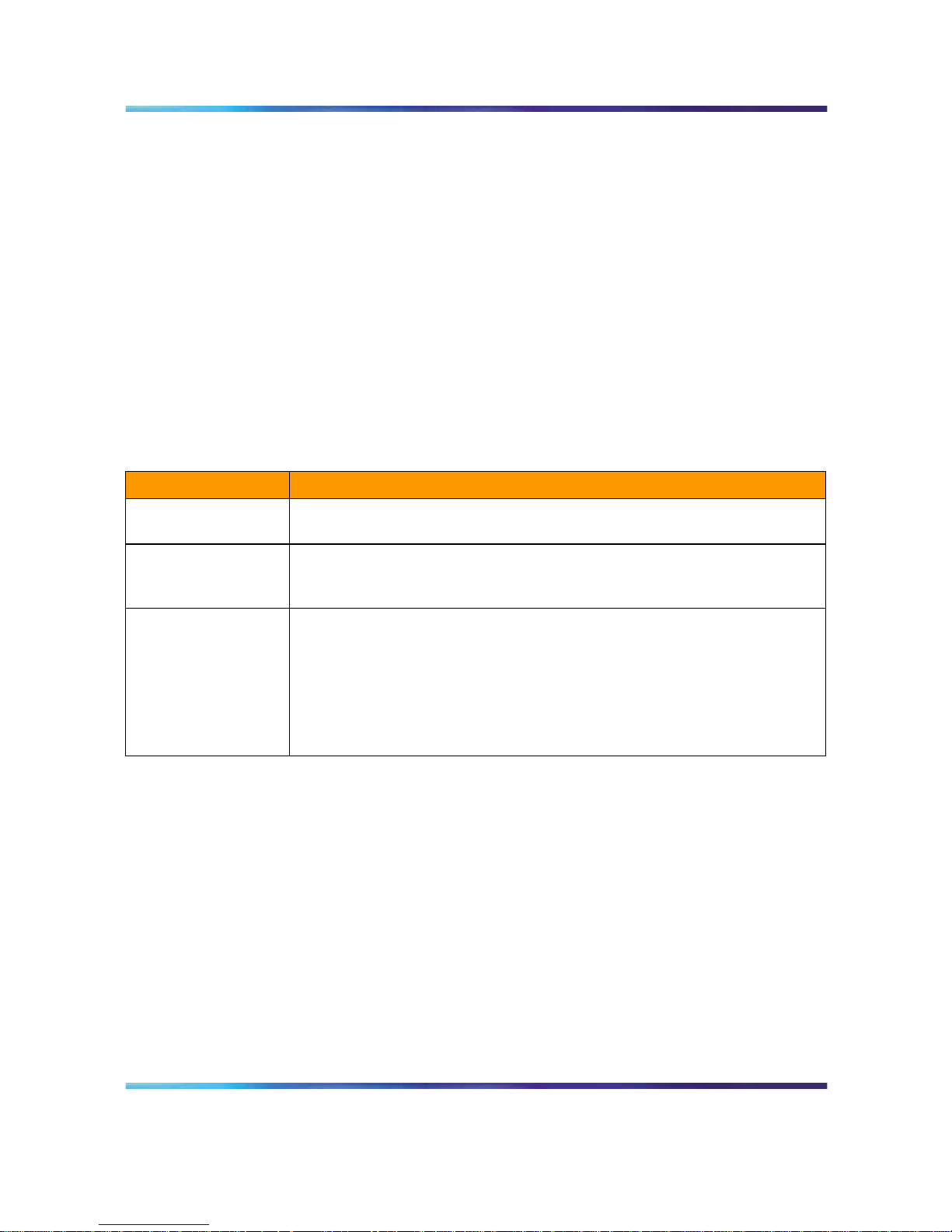
ICB card description
The ICB card has two PCMCIA sockets. PCMCIA hard drive cards store
the ICB voice files, application scripts, and MPU and DSP firmware. The
ICB comes with the PCMCIA hard drive. The bottom socket houses the
PCMCIA hard drive card that contains the current firmware and customer
data. Use the top socket to upgrade the firmware, and to backup and
restore customer data.
Nortel Communication Server 1000/Communication Server 2100 Solution/Meridian SL-100
Nortel Integrated Conference Bridge: Service Implementation Fundamentals
NN43001-558/555-4001-135 01.02 Standard
ICB Release 4 20 June 2007
Copyright © 2007, Nortel Networks
.
Page 25
Hardware overview 25
Figure 2 "ICB card" (page 25) shows the component side of the ICB card
and the faceplate. The component side shows the DRAM and the PCMCIA
socket locations. The faceplate shows the card LED and the PCMCIA
activity light-emitting diode (LED) indicators and the slot locations for
PCMCIA cards.
Figure 2
ICB card
The ICB faceplate provides the following:
Maintenance LED - The ICB faceplate provides a red LED to indicate the
enabled/disabled status of the card and to indicate the self-testing result
during power up or card insertion into an operating system. This LED
indicates the following:
•
The LED is lit when the ICB card is disabled.
•
The LED is off when the ICB card is enabled and ready for use.
• The LED blinks three times, runs software from the PCMCIA, then blinks
three times again and stays on. The LED remains on until the software
is enabled when the ICB card successfully completes the self-test.
PCMCIA activity indicator LEDs - These LEDs are next to the PCMCIA
slots and indicate the following:
•
The LED is lit when the PCMCIA card is disabled.
• The LED is off when the PCMCIA card is enabled and ready for use.
Nortel Communication Server 1000/Communication Server 2100 Solution/Meridian SL-100
Nortel Integrated Conference Bridge: Service Implementation Fundamentals
NN43001-558/555-4001-135 01.02 Standard
ICB Release 4 20 June 2007
Copyright © 2007, Nortel Networks
.
Page 26

26 Product description
•
The LED blinks when the PCMCIA card is in use.
Type II/III PCMCIA slots - The ICB faceplate provides two Type II/III
PCMCIA card slots. These slots house the PCMCIA cards. Install the
PCMCIA hard drive card that stores voice files, application scripts, and MPU
and DSP firmware in the lower slot. Use the upper slot for upgrading the
firmware, and backing up and restoring customer data.
External equipment
VT100 type terminal
Use a VT100 terminal for initial card configuration. After initial card
configuration, use the BUI to perform operations, administration and
maintenance (OA&M). Connect the terminal to the ICB RS-232 interface
using one of the following methods:
•
Direct connections:
— directly to the IPE module I/O panel
— directly to the DB-9 connector on the NT5D52 Ethernet Adapter
card installed on the I/O panel
•
Remote connections:
— to the IPE module I/O panel through a modem connection
The terminal interface must be set at 9600 baud, 8 data bits, 1 stop bit, and
no parity. The flow control is hard wired (do not use XON/XOFF flow control).
Ethernet application
ICB Ethernet use has the following characteristics:
•
The ICB Ethernet connection is separated from the external LAN traffic
by a firewall.
•
The Ethernet Adapter connection for ICB is NT5D52AA for the IPE
module application.
•
The Ethernet provider assigns the IP address for the ICB. Enter the IP
address from the Maintenance terminal.
•
To access the ICB CLI over the Ethernet, use a TELNET client on a PC
workstation or in the LAN.
ICB operation
The ICB provides flexibility in configuring conferences. Configure
conferences as follows:
•
pre-scheduled conferences with a fixed number of ports and start/stop
times
Nortel Communication Server 1000/Communication Server 2100 Solution/Meridian SL-100
Nortel Integrated Conference Bridge: Service Implementation Fundamentals
NN43001-558/555-4001-135 01.02 Standard
ICB Release 4 20 June 2007
Copyright © 2007, Nortel Networks
.
Page 27

ICB operation 27
•
pre-scheduled conferences with a variable numbers of ports, where
ports are added when required (if available) and subtracted by the
system automatically as conferees leave the conference
•
permanent bridges with fixed numbers of ports that can be used without
pre-scheduling the conference
The minimum duration of a conference is 15 minutes and the maximum
duration of a time-limited conference is 12 hours. The conference starting
time and duration can be scheduled in increments of 15 minutes.
The ICB card continuously monitors the audio signal level received from
each conferee and selects the two loudest signals for transmission. The two
loudest signals are summed and inserted into the PCM sample prior to their
transmission to other conferees. This implementation of the two loudest
signals improves the interrupting capability of a conference connection and
allows normal two-way conversation that all conferees can hear.
In addition to the conferee timeslots, the ICB provides a timeslot between
the MPU and the DSP. This timeslot transmits message prompts, entry
and exit tones, or both that the system broadcasts to all conferees when
requested by the MPU.
The ICB uses ACD features to route external incoming trunk and local line
conferees to their appropriate conferences. The ACD features provide
queuing, chairperson features, and event reporting for each conference.
The ACD features used by the ICB card provide the following:
•
easy software configuration
•
incoming calls, announcement on arrival, call management, and
reporting queues
•
operational statistics reports
•
enhanced call routing
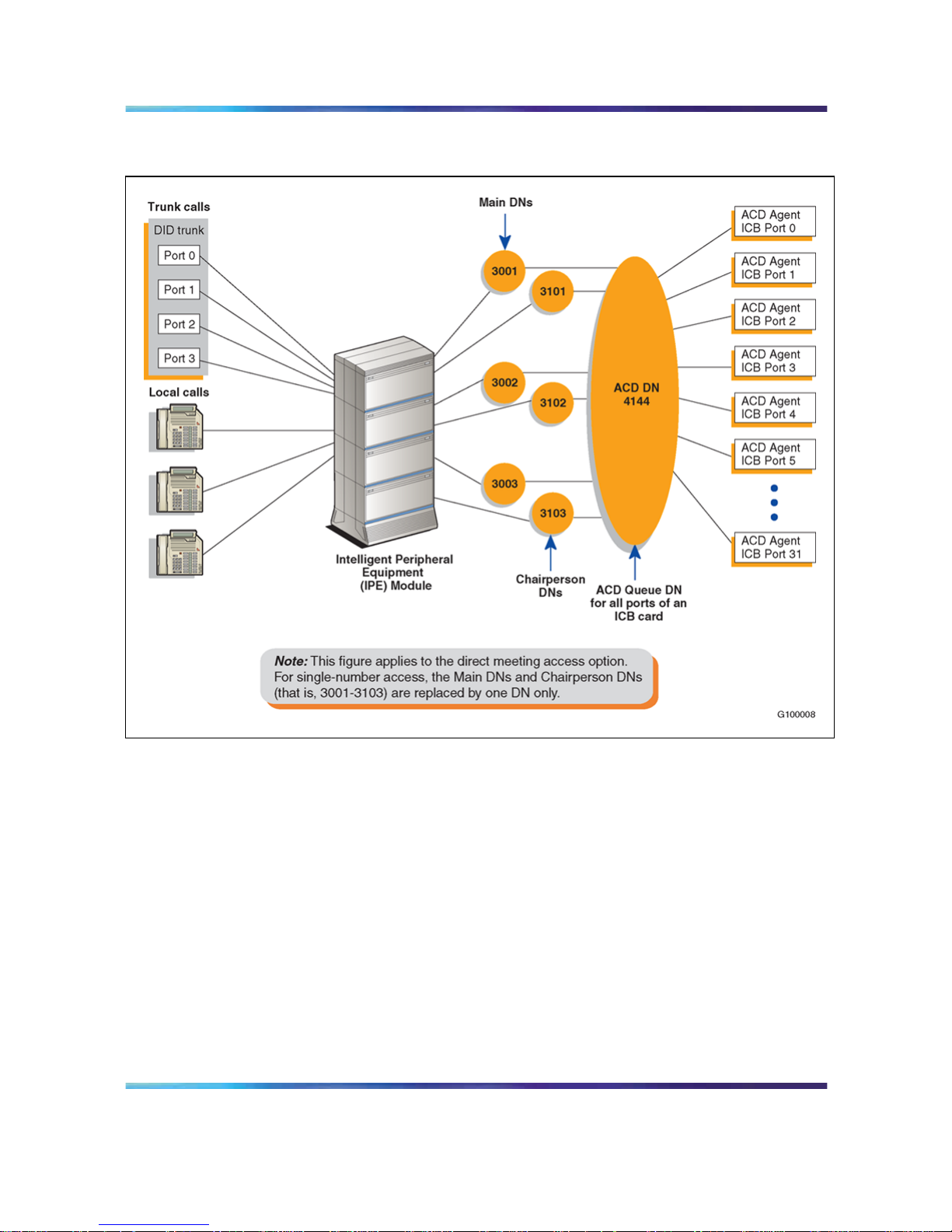
Figure 3 "Call routing with chairperson access" (page 28) shows the call
routing for three conferences and shows the conference chairperson access
DN for each conference. The figure also shows the ACD DN for the ACD
queue that controls the path of all ports on an ICB card. The right-hand side
of the figure shows the distribution of ICB ports as ACD agents.
Nortel Communication Server 1000/Communication Server 2100 Solution/Meridian SL-100
Nortel Integrated Conference Bridge: Service Implementation Fundamentals
NN43001-558/555-4001-135 01.02 Standard
ICB Release 4 20 June 2007
Copyright © 2007, Nortel Networks
.
Page 28
28 Product description
Figure 3
Call routing with chairperson access
Join the conference using the direct meeting access method
Assign a main DN and a chairperson DN, for each conference. The
main DN is the number the conferees dial to get into the conference and
the chairperson DN is the number the chairperson dials. Configure the
DNs in the Meridian/CS 1000 system when installing the ICB card. The
total number of DNs is equal to two times the number of simultaneous
conferences. For example, 10 simultaneous conferences require 20 DNs:
10 main DNs and 10 chairperson DNs.
When several conferences occur simultaneously in the same ICB card,
the conferee dials the DN assigned to a specific conference. The ICB
card identifies the dialed DN and routes the conferee to the appropriate
conference represented by that specific DN. The system assigns all ports on
the ICB card to the appropriate conference through the ACD DN assigned
Nortel Communication Server 1000/Communication Server 2100 Solution/Meridian SL-100
Nortel Integrated Conference Bridge: Service Implementation Fundamentals
NN43001-558/555-4001-135 01.02 Standard
ICB Release 4 20 June 2007
Copyright © 2007, Nortel Networks
.
Page 29

ICB operation 29
to that ICB card. The chairperson dials the chairperson DN to a specific
conference. This number is different from the DN dialed by the conferees for
the same conference.
The ICB performs DTMF detection on ICB ports identified as chairperson
ports. DTMF detects when conferees enter a conference password. A
conference can start without the chairperson. If all allocated ports for a
conference are taken up with conferees, the chairperson cannot join the
conference, unless a port is specifically reserved for the chairperson. The
chairperson can also join if the system allows conference expansion and
there are free, un-scheduled (floating) ports available.
The first conferee joining the conference hears an announcement indicating
that no other conferee has joined the conference, followed by 60 seconds of
music. The system repeats the announcement with 60 seconds of music,
until another conferee joins the conference.
Join the conference using the single DN access method
The single DN access method to all meetings provides users with a
alternative method of accessing the ICB. This feature reduces the amount of
Direct Inward Dialing (DID) numbers that have to be configured in the switch
and provides the following benefits:
•
Saves 20 DID numbers from the customer’s DID range.
•
Saves 20 ACD or Phantom DNs in the Meridian system thereby
providing a cost savings.
•
Simplifies installation as there is no DN pair configuration.
•
Saves work if a change in the numbering plan is required in the Meridian
system.
The only trade-off is that callers have an additional step when accessing
a meeting (that is, after dialing the single-access DN, they must enter the
chairperson, or meeting, DN of their specific meeting).
Figure 4 "Single DN access method (one ICB card)" (page 30) shows the
DN configuration for single DN access with one ICB card.
Nortel Communication Server 1000/Communication Server 2100 Solution/Meridian SL-100
Nortel Integrated Conference Bridge: Service Implementation Fundamentals
NN43001-558/555-4001-135 01.02 Standard
ICB Release 4 20 June 2007
Copyright © 2007, Nortel Networks
.
Page 30
30 Product description
Figure 4
Single DN access method (one ICB card)
The DNs on the left in Figure 4 "Single DN access method (one ICB card)"
(page 30) can be Phantom DNs or CDNs, instead of ACD DNs. The DNs
must be DID numbers.
In a dual-card system, each card requires its own single-access DN. In a
dual-card set, conferences that span the two cards do not support the single
DN access method. However, in a dual-card set, simple conferences that
use only one card support the single DN access method.
Figure 5 "Single DN access method (two ICB cards)" (page 31) shows the
DN configuration in a Meridian system for the single DN access method
when the system uses two ICB cards. Single DN access requires one DN,
instead of the separate 10 DNs required with direct meeting access.
The figure shows a configuration that supports the following:
•
Simple conference contained in the primary ICB - participants dial the
single-access DN at the top of the figure.
•
Simple conferences contained on the secondary ICB - participants dial
the single-access DN at the bottom of the figure.
•
Meetings spanning both cards - participants dial the "Dual meeting main
DN" in the middle of the figure and the chairperson dials the "Dual
meeting chairperson DN". The figure shows that dual-card meetings
do not use the single-access DNs.
Nortel Communication Server 1000/Communication Server 2100 Solution/Meridian SL-100
Nortel Integrated Conference Bridge: Service Implementation Fundamentals
NN43001-558/555-4001-135 01.02 Standard
ICB Release 4 20 June 2007
Copyright © 2007, Nortel Networks
.
Page 31

ICB operation 31
Figure 5
Single DN access method (two ICB cards)
Note: All DNs on the left side of the figure must be DID numbers.
Single DN access is mutually exclusive from the direct meeting access
method in a ICB card or card pair. Configure the card for one access
method; the system does not support combinations on the card or card pair.
Nortel Communication Server 1000/Communication Server 2100 Solution/Meridian SL-100
Nortel Integrated Conference Bridge: Service Implementation Fundamentals
NN43001-558/555-4001-135 01.02 Standard
ICB Release 4 20 June 2007
Copyright © 2007, Nortel Networks
.
Page 32

32 Product description
Callers to all meetings access the ICB by dialing one common fixed number.
The ICB prompts the caller for the meeting or chairperson DN to enter the
required meeting. In this mode of operation, configure the single-access
DN in the Meridian system and ICB only. Access DN pairs are pre-coded
in the card.
Expand the conference
Conference expansion allows the system to increase the number of
conferees if there are remaining ICB ports that are both unassigned and
unused. Allow or deny conference expansion for each conference using
the browser user interface (BUI) (see the "Add ports as needed field" in
the "Scheduling window" (page 93)).
When reserving the ICB ports for each simultaneous conference, the
system does not tag ports for a specific conference. The ICB counts the
number of reserved ports and compares these against the total number of
ports provided by the ICB card. The ICB then makes sure that the reserved
ports do not exceed the total number of ports provided by the ICB card.
If additional (non-scheduled) callers try to join a conference, but there are
no floating ports, or the system locks out additional conferees, the ICB card
issues an overflow tone. The system then disconnects the call.
If the system releases un-scheduled (floating) ports from a conference, they
are immediately available to be used by other conferences that have the
expansion feature enabled.
End the conference
When scheduling a conference, indicate the number of ports, start time,
and duration of that conference. The conference ends based on the start
time and conference duration. Ten minutes before the end of a conference,
the ICB card issues an announcement warning the conferees that the
conference terminates in 10 minutes. Two minutes before the end of a
conference, the ICB card issues a second announcement warning the
conferees that the conference terminates in two minutes.
When the conference time expires, the ICB card issues the final warning to
the conferees. The ICB sends a release message to the Meridian system for
all associated ICB ports. These ports become available for the next planned
conference. If there is no other scheduled conference, they become floating
ports which the system does not reserve for any conference. Floating ports
are available to expand conferences in progress.
Conferees can exit a conference at any time. The ICB detects when a
conferee exits the conference. If enabled, the ICB announces the conferee’s
name. When one conferee is on the conference, the system issues an
Nortel Communication Server 1000/Communication Server 2100 Solution/Meridian SL-100
Nortel Integrated Conference Bridge: Service Implementation Fundamentals
NN43001-558/555-4001-135 01.02 Standard
ICB Release 4 20 June 2007
Copyright © 2007, Nortel Networks
.
Page 33

ICB operation 33
announcement that only one conferee is present, followed by 60 seconds
of music. The system repeats this announcement and the music, until at
least one more conferee joins in, or the ICB terminates the conference at
the scheduled end time, or if the conferee or chairperson issues the stop
music command (*19).
Note: A conference can begin and end two minutes before the defined
time. This feature allows the system to close all terminating conferences
two minutes earlier and start all scheduled conferences immediately
after closing the terminating conferences. This feature is important when
terminating and starting conferences use some of the same DNs.
Nortel Communication Server 1000/Communication Server 2100 Solution/Meridian SL-100
Nortel Integrated Conference Bridge: Service Implementation Fundamentals
NN43001-558/555-4001-135 01.02 Standard
ICB Release 4 20 June 2007
Copyright © 2007, Nortel Networks
.
Page 34

34 Product description
Nortel Communication Server 1000/Communication Server 2100 Solution/Meridian SL-100
Nortel Integrated Conference Bridge: Service Implementation Fundamentals
NN43001-558/555-4001-135 01.02 Standard
ICB Release 4 20 June 2007
Copyright © 2007, Nortel Networks
.
Page 35

35
Engineering guidelines
Purpose
This chapter provides guidelines for engineering ICB Release 4.
Engineering guidelines can vary depending on the system platform. The
chapter includes the following sections:
•
"System requirements" (page 35) - outlines the software and hardware
requirements for the Meridian 1, CS 1000, and CS 2100/Meridian
SL-100.
• "System capacity" (page 37) - outlines the system capacity requirements
for the Meridian 1, CS 1000, and CS 2100/Meridian SL-100.
•
"System compatibility" (page 37) - lists the various compatible systems.
•
"Automatic call distribution resource allocation" (page 38) - describes
the ACD DN resource requirements.
•
"LAN configuration" (page 39) - provides guidelines for configuring the
LAN options.
System requirements
Software
The required system software is as follows:
•
Meridian 1 - X11 Release 17 supports ICB Release 4 with up to 16
ports per card; X11 Release 22 and later supports ICB Release 4 with
up to 32 ports per card.
•
CS 1000 - Release 1 and above supports ICB Release 4 with up to 32
ports per card.
•
Meridian SL-100 - MSL09 and later supports ICB Release 4 with up to
32 ports per card using the feature Flexible Voice/Data TN.
The system software must contain the basic and advanced automatic call
distribution (ACD) features and routing software.
Nortel Communication Server 1000/Communication Server 2100 Solution/Meridian SL-100
Nortel Integrated Conference Bridge: Service Implementation Fundamentals
NN43001-558/555-4001-135 01.02 Standard
ICB Release 4 20 June 2007
Copyright © 2007, Nortel Networks
.
Page 36

36 Engineering guidelines
Meridian 1 and CS 1000 software packages
In addition to standard basic software, the following software packages
are required:
•
ACD basic package (45)
•
ACD advanced features (41)
•
Digital set (88)
•
End-to-end signaling (10) - required if chairperson calls locally within
the same switch
• Phantom TN (254), optional, but required if Phantom TN is used
•
Network ACD Enhanced Overflow (178), optional, but required for the
dual-card configuration
•
The following packages are optional, but are required for billing:
— Call Detail Recording (CDR) package 4
— CDR with Charge Account (CHG) package 23
— Charge Account/Authorization Code Base (CAB) package 24
Meridian SL-100 software packages
In addition to the standard Meridian SL-100 software, the following software
packages are required:
•
ACD Basic, ACD Routing Enhancement
•
MSL Digital Phones M2000-Display
•
MSL Flex LEN on IPE
•
MSL Enhanced Peripheral Equipment (IPE)
Hardware
Table 2 "Hardware specifications" (page 36) describes the ICB hardware
specifications.
Table 2
Hardware specifications
Item Descriptions
Port capacity 12-32 ports on a single card.
Up to 62 ports in a dual-card configuration, unless chairperson control is
required on the second card, in which case the capacity is 60 ports.
Capacity upgrades Upgradeable from 12 to 62 ports.
Maximum number
of conferences
Up to 10 simultaneous conferences with a total of 32 conferee ports per
card.
Nortel Communication Server 1000/Communication Server 2100 Solution/Meridian SL-100
Nortel Integrated Conference Bridge: Service Implementation Fundamentals
NN43001-558/555-4001-135 01.02 Standard
ICB Release 4 20 June 2007
Copyright © 2007, Nortel Networks
.
Page 37

System compatibility 37
Item Descriptions
Maximum number
of BUI sessions
Up to 20 simultaneous user sessions on the BUI. Same is true in dual-card
configuration. There can be up to 500 users per card.
Maximum number
of TUI sessions
Only one user can be active in a TUI session. While one TUI user is active,
other users will wait in the ACD queue.
PCMCIA card PCMCIA Type II or III.
System interface DS-30X, CE-MUX, Card LAN, Ethernet Adapter.
Maintenance
terminal
Optivity, VT-100 terminal or PC with VT100 emulation.
Power requirements Power is supplied by the power supply of the shelf/module where the ICB
card is installed. Each ICB card requires a total maximum power of 3.5
watts.
Real time impact Comparable to that of a digital line card (DLC).
System capacity
Physical Capacity
Each ICB card occupies one slot on the Gateway/IPE chassis shelf. The
total number of ICB cards per system is limited by these factors:
•
For Meridian 1 or CS 1000M: The number of IPE shelves multiplied by
eight. Option 11C and Wall-Mount systems are limited to six cards.
•
For CS 1000: The number of Gateway chassis shelves multiplied by
four cards.
•
For CS 2100/Meridian SL-100: Up to eight cards can be supported
per IPE shelf.
System compatibility
Meridian 1 and Option 11
ICB Release 4 is compatible with the following Meridian 1/Option 11
systems:
•
Option 11C, 11E, 11C Mini
•
Option 21 and 21E
•
Option 51, 51C
•
Option 61, 61C
•
Option 71
•
Option 81, 81C
•
SL-1 systems with IPE upgrade (NT and XT)
Nortel Communication Server 1000/Communication Server 2100 Solution/Meridian SL-100
Nortel Integrated Conference Bridge: Service Implementation Fundamentals
NN43001-558/555-4001-135 01.02 Standard
ICB Release 4 20 June 2007
Copyright © 2007, Nortel Networks
.
Page 38

38 Engineering guidelines
CS 1000
ICB Release 4 is compatible with all CS 1000 systems.
CS 2100/Meridian SL-100 system compatibility
ICB Release 4 is compatible with all CS 2100/Meridian SL-100 system
configurations.
Automatic call distribution resource allocation
The ACD function routes incoming calls to the ICB, where each ICB port
operates as an ACD agent. All ICB ports are part of the same ACD queue
and operate as a pool of ports with equal status. The system identifies the
ACD queue with an ACD DN that handles the connection of conferees (ACD
agents) to the appropriate conference.
ACD resources must be reviewed in the Incremental Software Management
(ISM) of the customer configuration, if applicable. Each ICB port represents
an ACD agent that uses a Terminal Number (TN)/Line Equipment Number
(LEN) from the system resources.
The configuration DN and the corresponding TNs on the CS 1000, or LENs
on the CS 2100/Meridian SL-100, are system resources. The system
resources allocated to the ICB must be subtracted from the overall system
resources and cannot be used for any other application, as long as they are
assigned for ICB use.
Note: If a customer uses Agent ID and the direct meeting access
method, the agent IDs must be consecutive (for example, 00-31).
Each ICB card, using the direct meeting access method, requires the
following:
•
One ACD group for each ICB card.
•
Assign ACD agent TNs/LENs and corresponding M2616 digital sets.
Each configured ICB port appears as an M2616 digital set of an ACD
agent. The number of TNs/LENs is equal to the maximum number of
ports provided by the ICB card. For an ICB with 32 ports active, the
configuration requires 32 TNs/LENs. TNs/LENs require 32 DNs for the
ACD incalls key and 32 DNs for the secondary directory number (SDN)
key (Key 2).
•
An ICB card configured to the maximum capacity of 32 ports and 10
simultaneous conferences requires 87 ACD DNs and 32 TNs/LENs
as follows:
— one ACD DN assigned to the ICB card
— 32 TNs/LENs assigned to the 32 ports (1 PDN and 1 SDN for each
TN/LEN; these can be internal DNs - non-DID)
Nortel Communication Server 1000/Communication Server 2100 Solution/Meridian SL-100
Nortel Integrated Conference Bridge: Service Implementation Fundamentals
NN43001-558/555-4001-135 01.02 Standard
ICB Release 4 20 June 2007
Copyright © 2007, Nortel Networks
.
Page 39

LAN configuration 39
— 20 ACD DID DNs (10 DN pairs) for dialing into the potential
conferences
Note: For single-number access, replace this with 1 DN.
— 1 DN for TUI access
Full 62-port dual-card conferencing, using the direct meeting access
method, requires the following:
•
Two ICB cards and six ACD groups as follows:
— 64 ACD agents (32 for each card), non-DID
— 64 secondary DNs for these agents, non-DID
— 36 DNs for simple conferences (9 pairs in each card)
Note: For single-number access, replace this with 2 DNs (1 for
each card).
— 1 DN for dual-card conference access
— 1 DN for dual-card chairperson access
— 1 DN for the link DN, non-DID
— 1 DN for the transfer DN, non-DID
— 2 DNs for TUI access (1 for each card)
This provides a total of 170 DNs, 40 of which are DID.
•
Assign an Ethernet port to each ICB card with an IP address, subnet
mask, and gateway during installation.
Note: On the CS 2100/Meridian SL-100, verify that there are enough
DS30A links back to the extended peripheral module (XPM) to handle
the traffic.
LAN configuration
ICB customers should select one of the following alternativesfor BUI access:
•
users and administrators access the ICB from the global internet (the
new capability of MICB Release 3)
•
users and administrators access the ICB from the customer LAN/intranet
only (existing MICB Release 2 capability)
Global internet access
Global internet access requires careful configuration of security elements.
Figure 6 "Global internet access example" (page 40) shows a sample
configuration.
Nortel Communication Server 1000/Communication Server 2100 Solution/Meridian SL-100
Nortel Integrated Conference Bridge: Service Implementation Fundamentals
NN43001-558/555-4001-135 01.02 Standard
ICB Release 4 20 June 2007
Copyright © 2007, Nortel Networks
.
Page 40

40 Engineering guidelines
Figure 6
Global internet access example
In typical configurations, the firewall does not allow any kind of access from
the World Wide Web into the C-LAN. Only access from the C-LAN hosts to
the World Wide Web is allowed (for example, HTTP and FTP).
Hosts that need to be accessed from the World Wide Web must be placed in
a special sub-network called the Green and Red LAN. The firewall isolates
the Green and Red LAN from the C-LAN. Devices that can be accessed
from the World Wide Web are put into this segregated LAN segment. Nortel
Networks recommends that the Green and Red LAN be the location of
the ICB connection.
On the other hand, C-LAN hosts require open access to the ICB for
administration and maintenance.
Nortel Communication Server 1000/Communication Server 2100 Solution/Meridian SL-100
Nortel Integrated Conference Bridge: Service Implementation Fundamentals
NN43001-558/555-4001-135 01.02 Standard
ICB Release 4 20 June 2007
Copyright © 2007, Nortel Networks
.
Page 41

LAN configuration 41
Table 3 "Firewall access permissions" (page 41) summarizes the
recommended access permissions allowed by the firewall. All other paths
not in the table should be denied.
Table 3
Firewall access permissions
Source
Destination Protocol
WWW ICB HTTP
C-LAN ICB HTTP, FTP, TELNET
ICB WWW FTP (optional; allows upgrade from
the web)
ICB C-LAN FTP
ICB Mail Server SMTP
Notes
Take the following notes into consideration:
•
Technically, a firewall can be configured to enforce these access
restrictions even when the ICB is in the C-LAN. However, a Green and
Red LAN is usually used, because it is safer.
•
Cards of a dual-ICB set must be in the same LAN segment, with no
restrictions between them.
LAN/intranet access only
In this configuration, the ICB is not accessible from anywhere in the World
Wide Web (assuming this policy is enforced by the firewall). There are
two options for this type of configuration: C-LAN connection and E-LAN
connection.
Figure 7 "LAN/intranet access only - C-LAN connection" (page 42) shows
an example of the C-LAN connection.
Nortel Communication Server 1000/Communication Server 2100 Solution/Meridian SL-100
Nortel Integrated Conference Bridge: Service Implementation Fundamentals
NN43001-558/555-4001-135 01.02 Standard
ICB Release 4 20 June 2007
Copyright © 2007, Nortel Networks
.
Page 42

42 Engineering guidelines
Figure 7
LAN/intranet access only - C-LAN connection
Nortel Communication Server 1000/Communication Server 2100 Solution/Meridian SL-100
Nortel Integrated Conference Bridge: Service Implementation Fundamentals
NN43001-558/555-4001-135 01.02 Standard
ICB Release 4 20 June 2007
Copyright © 2007, Nortel Networks
.
Page 43

LAN configuration 43
Figure 8 "LAN/intranet access only - E-LAN connection" (page 43) shows
an example of the E-LAN connection.
Figure 8
LAN/intranet access only - E-LAN connection
Notes
The following notes apply to LAN/intranet access only:
•
The ICB does not interact with the Meridian system through the E-LAN,
so logically there is no requirement to put it there. In addition, if the
E-LAN is completely separated from the C-LAN, the ICB cannot be in
the E-LAN.
•
Nortel Networks recommends that customer try not to put any BUI traffic
on the E-LAN if possible.
Nortel Communication Server 1000/Communication Server 2100 Solution/Meridian SL-100
Nortel Integrated Conference Bridge: Service Implementation Fundamentals
NN43001-558/555-4001-135 01.02 Standard
ICB Release 4 20 June 2007
Copyright © 2007, Nortel Networks
.
Page 44

44 Engineering guidelines
•
Each site should select the most convenient option, taking into account
the physical LAN endpoints available near the ICB card.
•
When there are multiple ICBs (that is, more than three) and the BUI is
used frequently, the BUI traffic can load the E-LAN, so it may be better
to connect the cards to the C-LAN.
• The ICB has a broadcast-storm protection mechanism: it shuts off
the LAN port (temporarily) when traffic is too heavy. Nortel Networks
recommends that the ICB be put in a "quiet" LAN segment to get a
better response time.
Summary of LAN installation information
Use the following steps when installing and configuring the LAN:
Step Action
1
Determine whether the ICB is to be accessed from the World Wide
Web.
2
If yes, coordinate the firewall configuration with your IS group
according to Table 3 "Firewall access permissions" (page 41).
3
Determine what is the physical connection point of the ICB. Note
these requirements: 10Base-T or 100Base-T, full-duplex.
4
Get the following ICB IP parameters from your IS group: IP address,
gateway address, and subnet mask.
5
Get the Mail Server IP address from your IS group. Confirm that the
ICB is allowed to access this server by SMTP.
—End—
Testing:
Use the following steps to test the LAN configuration:
Step Action
1
After the ICB is installed and the IP parameters are configured, try to
"ping" from any host in the C-LAN to the ICB or from the ICB to a
host on the C-LAN.
2
In the case of World Wide Web access, try accessing the ICB from a
browser (HTTP access).
—End—
Nortel Communication Server 1000/Communication Server 2100 Solution/Meridian SL-100
Nortel Integrated Conference Bridge: Service Implementation Fundamentals
NN43001-558/555-4001-135 01.02 Standard
ICB Release 4 20 June 2007
Copyright © 2007, Nortel Networks
.
Page 45

45
Installation and configuration
Purpose
This chapter describes how to prepare the system for installation, install
the ICB into:
•
the IPE module for Meridian 1
•
the Option 11 shelf
•
the Media Gateway for CS 1000
•
the IPE module for CS 2100/Meridian SL-100
This chapter also describes how to connect the ICB to the administration
terminal, and configure the card.
The chapter contains the following sections:
•
"Getting started" (page 45) - describes the steps to use when preparing
for an installation.
•
"CS 1000 configuration" (page 47) - shows how to configure the
Meridian 1 and CS 1000.
•
"CS 2100/Meridian SL-100 configuration" (page 55) - shows how to
configure the Meridian SL-100.
•
"ICB installation and configuration procedures" (page 65) - shows how
to install the card and set up the web server.
• "ICB Installation Wizard" (page 74) - describes how to use the BUI’s
Installation Wizard to complete configuration.
Getting started
To begin the installation, unpack and inspect the components, take
inventory, and determine which IPE card slot(s) in which to install the ICB
card(s). See Table 1 "ICB hardware list" (page 24) for a complete listing
of the ICB hardware.
Nortel Communication Server 1000/Communication Server 2100 Solution/Meridian SL-100
Nortel Integrated Conference Bridge: Service Implementation Fundamentals
NN43001-558/555-4001-135 01.02 Standard
ICB Release 4 20 June 2007
Copyright © 2007, Nortel Networks
.
Page 46

46 Installation and configuration
Unpack and inspect the equipment
Unpack and inspect the equipment for damage. Follow the steps in
Procedure 1 "Prepare for the installation" (page 46), before performing the
installation and configuration procedures in this chapter.
Procedure 1
Prepare for the installation
Step Action
1
Remove items from the installation site that can generate static
charge.
2
Use antistatic spray if the site is carpeted.
3
Ground yourself before handling any equipment.
4
Remove equipment carefully from its packaging. Save the
packaging, in case the card has to be returned.
5
Inspect the equipment for faults or damage. Report any damaged
component to your Nortel Networks representative and the company
who delivered the equipment.
—End—
Take inventory
After unpacking and inspecting the equipment, verify that all necessary
components are on site before beginning the installation. Check the
equipment received against the shipping documents. Report any missing
parts to your Nortel Networks representative.
Verify IPE Slot(s)
The ICB card can be installed in any IPE card slot associated with full 50-pin
I/O cables. Table 4 "ICB installation into card slots" (page 46) lists the
Meridian system modules and the card slots appropriate for ICB installation.
Table 4
ICB installation into card slots
Meridian system modules
ICB card slots
NT8D37BA/EC IPE modules, and
NT8D11BC/ED CE/PE modules.
All available IPE card slots.
NT8D37AA/DC IPE modules. IPE card slots 0, 4, 8, and 12.
CS 1000. 1, 2, or 3 of the Media Gateway,
or slots 7, 8, 9, or 10 of the Media
Gateway Expansion.
Nortel Communication Server 1000/Communication Server 2100 Solution/Meridian SL-100
Nortel Integrated Conference Bridge: Service Implementation Fundamentals
NN43001-558/555-4001-135 01.02 Standard
ICB Release 4 20 June 2007
Copyright © 2007, Nortel Networks
.
Page 47

CS 1000 configuration 47
Determine the access method
Select the access method, single-number or direct meeting access, the
system will be using. With direct access, configure 10 DN pairs. In
single-number access mode, configure only the single-access DN. In both
cases, the BUI provides instructions about what to do next.
Installing the NTCW84JA I/O Panel Filter Connector for a Large System
For Large Systems, the standard IPE module I/O filtering is provided
by the 50-pin filter connectors mounted in the I//O panel on the back of
the IPE shelf. The filter connector attaches externally to the MDF cables
and internally to the NT8D81AA backplane to the I/O panel ribbon cable
assembly. For 100BaseTX TLAN operation, the standard I/O filter connector
must be replaced with the NTCW84JA ITG Line-specific I/O filter connector
for the slot occupied by the ICB card.
Note: The NTCW84JA ITG-filter connector is not required on Small
Systems or Succession 1000 systems.
CAUTION
For Large systems manufactured between 1998-1999 and shipped
in North America, IPE modules have the NT8D81BA backplane
to I/O panel ribbon cable assembly with a non-removable filter
connector. The NT8D81BA is compatible with a 10BaseT TLAN. If
a 100BaseT TLAN is required, order the NT8D81AA Backplane
to I/O panel ribbon cable assembly to replace it. Do not install
the NTCW84JA filter connector onto the existing non-removable
filter connector.
CS 1000 configuration
Prior to installing any of the ICB hardware, configure the system software for
the ICB card(s) through the system TTY terminal.
Summary
The following summarizes the tasks for configuring the CS 1000:
1. LD 23 - Define the ACD DN assigned to the ICB card.
2. Define DNs using either:
LD 23 - Define ACD DNs and assign them to the ICB card.
or
LD 10 - Define Phantom TNs and forward them to the ACD DN assigned
to the ICB card.
3. LD 11 - Configure ICB ports as digital sets.
4. LD 23 - Configure the main DN for dual-card conferences.
Nortel Communication Server 1000/Communication Server 2100 Solution/Meridian SL-100
Nortel Integrated Conference Bridge: Service Implementation Fundamentals
NN43001-558/555-4001-135 01.02 Standard
ICB Release 4 20 June 2007
Copyright © 2007, Nortel Networks
.
Page 48

48 Installation and configuration
5. LD 15 - Configure the CDR data if the feature Charge Account is used
for billing.
Assign ACD DNs
The first step is to assign ACD queue.
Table 5
LD 23 - Define the ACD queue assigned to the ICB card
Prompt Response Description
REQ NEW Add new data.
TYPE ACD ACD data block.
CUST
xx
Customer number.
ACDN
xxxx
ACD DN assigned to the ICB card.
MAXP
32
Maximum number of ACD agent positions.
HOML NO Logout on handset removal.
Table 6
LD 23 - Assign the ACD DNs for the ICB card
Prompt Response Description
REQ NEW New control data block.
TYPE ACD ACD data block.
CUST
xx
Customer number.
ACDN
xxxx
Conferee (main) or chairperson DN.
MAXP
1
Maximum number of ACD agent positions.
NCFW
xxxx
ACD DN assigned to ICB card.
Note: Repeat commands in this table for each ACD DN being configured.
Note: The number of DNs defined for each ICB card using direct
meeting access depends on the number of conferences and bridges
specified on the card. A maximum of 10 conferences can be configured
requiring 20 DNs, two for each conference. One DN is for the conferees
to call in (the main DN) and one DN is for the conference chairperson.
Define Phantom TN blocks
Phantom TNs can be used, instead of ACD DNs, to serve as chairperson
DNs, conferees DNs and TUI DNs.
Enter the CS 1000 definitions for the Phantom TN in LD 10 as follows:
1. The specific TN and DN vary by site.
Nortel Communication Server 1000/Communication Server 2100 Solution/Meridian SL-100
Nortel Integrated Conference Bridge: Service Implementation Fundamentals
NN43001-558/555-4001-135 01.02 Standard
ICB Release 4 20 June 2007
Copyright © 2007, Nortel Networks
.
Page 49

CS 1000 configuration 49
Those variables are represented by "x" in Figure 9 "Phantom TN
definitions (LD 10)" (page 49).
2. CFXA is the Class of Service (CLS) that enables Call Forwarding.
3. The last four variables in the screen (under FTR) are the main ACD
DNs in LD 23.
Figure 9
Phantom TN definitions (LD 10)
The next step is to configure ICB ports as digital sets.
Table 7
LD 11 - Configure ICB ports as digital sets
Prompt Response Description
REQ NEW Add new data.
TYPE
2616
Digital telephone set M2616.
TN lscu
scu
Terminal number of the ICB card, Options 51C, 61C, and 81C.For
Option 11C and CS 1000.
Note: The administrator should consider chairperson dial-out restrictions through the ICB ports to
prevent international dial-out.
Nortel Communication Server 1000/Communication Server 2100 Solution/Meridian SL-100
Nortel Integrated Conference Bridge: Service Implementation Fundamentals
NN43001-558/555-4001-135 01.02 Standard
ICB Release 4 20 June 2007
Copyright © 2007, Nortel Networks
.
Page 50

50 Installation and configuration
Prompt Response Description
CUST
xx
Customer number.
CLS FLXA
VCE,
WTA
FLXA = Flexible Voice/Data Allowed.
VCE = Voice.
WTA = Warning Tone Allowed.
ACD agent (Use FLXA).
KEY 0 ACD
<ACD DN>
<CLI>
<pos ID>
ACD DN plus CLI plus position ID.
KEY 1SCR<anyDN> Line key.
KEY 2 NRD Not ready key.
KEY 3 MSB Make set busy key.
KEY 4 TRN Call transfer key.
KEY 9 CHG Change key. Use with CDR and billing feature.
Note: The administrator should consider chairperson dial-out restrictions through the ICB ports to
prevent international dial-out.
The number of virtual ACD agents of the ACD queue is equal to the number
of ICB ports. For example, if 12 ports are enabled, define 12 ACD agents. If
the TN for the ICB card is specified as 28 0 6, then TNs for the 12 agents
are specified as 28 0 6 0 through 28 0 6 11.
Note: Agent IDs must be consecutive (for example, 2000-2031).
Figure 10 "LD 20 ICB configuration" (page 51) shows a sample LD 20
printout of a built ICB port.
Nortel Communication Server 1000/Communication Server 2100 Solution/Meridian SL-100
Nortel Integrated Conference Bridge: Service Implementation Fundamentals
NN43001-558/555-4001-135 01.02 Standard
ICB Release 4 20 June 2007
Copyright © 2007, Nortel Networks
.
Page 51

CS 1000 configuration 51
Figure 10
LD 20 ICB configuration
Nortel Communication Server 1000/Communication Server 2100 Solution/Meridian SL-100
Nortel Integrated Conference Bridge: Service Implementation Fundamentals
NN43001-558/555-4001-135 01.02 Standard
ICB Release 4 20 June 2007
Copyright © 2007, Nortel Networks
.
Page 52

52 Installation and configuration
Configure DNs for a dual-card conference
When a dual-card conference is defined, two meetings are defined on
two cards. First, the meeting is booked on the primary card allocating the
maximum free ports. Second, the meeting is booked on the secondary
card allocating the rest of free ports for the dual-card conference. The user
defines a dual-card conference only on the primary card.
When a user dials into a dual-card conference, the call can terminate either
on the primary or on the secondary card. Calls to the dual-card conference
main ACD DN are forwarded according to the ACD time overflow night table.
On both cards (primary and secondary), the user cannot use the dual-card
conference pair DNs for a simple meeting. Therefore, nine DNs are
available for simple meeting and bridges.
For a dual-card configuration, one card functions as the primary card and
the other as the secondary card. Define for each card an ACD data block
with an ACD DN in LD 23, as shown in Table 5 "LD 23 - Define the ACD
queue assigned to the ICB card" (page 48).
For the primary card, configure the following DNs:
•
DN pairs (up to nine) - These pairs serve as chairperson and conferee
DNs for single-card conferences (less than 32 ports) on the primary card.
Note: If single-number access is being used, DN pairs are not
required. Instead, define the single-number access DN in this step
which callers use to access a simple conference on the primary card.
•
TUI DN - This is the DN that users dial to set up single-card conferences
on the primary card. Do not configure this DN, if the TUI is not going
to be used.
•
Chairperson DN - This is the DN that chairperson of a dual-card
conference dials to enter a dual-card conference. This DN is required
for dual-card setup.
Therefore, for the primary card, configure up to 20 DNs in LD 23 that Night
Call Forward (NCFW) to the ACD DN of the primary card.
For the secondary card, configure the following DNs:
•
DN pairs (up to nine) - These pairs serve as chairperson and conferee
DNs for single-card conferences (less than 32 ports) on the secondary
card.
Note: If single-number access is being used, DN pairs are not
required. Instead, define the single-number access DN in this step
which callers use to access a simple conference on the secondary
card.
Nortel Communication Server 1000/Communication Server 2100 Solution/Meridian SL-100
Nortel Integrated Conference Bridge: Service Implementation Fundamentals
NN43001-558/555-4001-135 01.02 Standard
ICB Release 4 20 June 2007
Copyright © 2007, Nortel Networks
.
Page 53

CS 1000 configuration 53
•
TUI DN - This is the DN that users dial to set up single-card conferences
on the secondary card. Do not configure this DN, if the the TUI is not
going to be used.
•
Transfer DN - This is the DN that transfers dual-card conference
participants from the primary card to the secondary card when the
primary card reaches capacity. The primary card fills up first in a
dual-card conference. Configure this DN for dual-card setup.
•
Link DN - This is the DN the creates a speech path between the primary
card and the secondary card for dual-card conferences. Configure this
DN for dual-card setup.
Therefore, for the secondary card, configure up to 22 DNs in LD 23 that
Night Call Forward (NCFW) to the ACD DN of the secondary card.
The main DN must also be configured for the dual-card conference. The
main DN is the DN that conferees dial to enter the dual-card conference.
When the conferees dial the main DN, the main DN forwards them to the
ACD queue of the primary card. When the primary card becomes full, the
transfer DN transfers further conferees to the secondary card. Use Table
8 "LD 23 - Configure the main DN for dual-card conferences" (page 53) to
configure the main DN for dual-card conferences.
Table 8
LD 23 - Configure the main DN for dual-card conferences
Prompt Response Description
REQ NEW Add new data.
TYPE ACD ACD data block.
CUST
xx
Customer number.
ACDN
xxxx
The main DN for dual-card conferences.
MAXP
1
Maximum number of ACD agent positions.
Note: Carriage return to the end and start again.
REQ NEW New control data block.
TYPE NACD Network ACD data block.
CUST
xx
Customer number.
ACDN
xxxx
The main DN for dual-card conferences.
TABL N Night time overflow table.
- TRGT
xxxx 0
xxxx is the ACD DN of the primary card.0 is the time, in seconds,
for an immediate transfer to the primary card.
- TRGT
yyyy 2
yyyy is the ACD DN of the secondary card.2 is the time, in
seconds, for a delayed transfer to the secondary card.
Nortel Communication Server 1000/Communication Server 2100 Solution/Meridian SL-100
Nortel Integrated Conference Bridge: Service Implementation Fundamentals
NN43001-558/555-4001-135 01.02 Standard
ICB Release 4 20 June 2007
Copyright © 2007, Nortel Networks
.
Page 54

54 Installation and configuration
Table 9 "Sample dialing plan for a 62-port dual-card configuration" (page 54)
shows a sample dialing plan for a 62-port dual-card configuration.
Table 9
Sample dialing plan for a 62-port dual-card configuration
Description of DNs
DNs for the
primary card
DNs for the
secondary card Configure in...
ACD DN
7000 8000
LD 23
Pair DNs for
single-card
conferences
7001-7018 (NCFW =
7000 in LD 23)
8001-8018 (NCFW =
8000 in LD 23)
LD 23
TUI DNs 7019 (NCFW = 7000) 8019 (NCFW = 8000) LD 23
Chairperson DNs 7020 (NCFW = 7000) LD 23
Transfer DN N/A 8021 (NCFW = 8000) LD 23
Link DN N/A 8022 (NCFW = 8000) LD 23
Main DN 7021 (TRGT = 7000
0)
7021 (TRGT = 8000
2)
LD 23
Note: Because of the number and variety of DNs programmed for the
dual-card setup, Nortel Networks recommends creating a dialing plan
chart similar to Table 9 "Sample dialing plan for a 62-port dual-card
configuration" (page 54). Refer to this chart when configuring the
primary and secondary card attributes, including the dual-card settings,
in the administration BUI.
Finally, configure each port on the primary and secondary cards as a digital
set. See Table 7 "LD 11 - Configure ICB ports as digital sets" (page 49).
Assign CDR data
If charge account is used for CDR billing, then configure the feature Charge
Account for CDR billing. Remember to define Key 9 on all ICB key ports.
See Table 10 "LD 15 - Define the charge account for CDR data" (page 54).
Table 10
LD 15 - Define the charge account for CDR data
Prompt Response Description
REQ CHG Change customer data.
TYPE CDR_DATA CDR data block.
CHLN
23
Set the charge account number length to 23.
Nortel Communication Server 1000/Communication Server 2100 Solution/Meridian SL-100
Nortel Integrated Conference Bridge: Service Implementation Fundamentals
NN43001-558/555-4001-135 01.02 Standard
ICB Release 4 20 June 2007
Copyright © 2007, Nortel Networks
.
Page 55

CS 2100/Meridian SL-100 configuration 55
CS 2100/Meridian SL-100 configuration
Single-card configuration
After installing the ICB card(s) and connecting the terminal for CLI access
and the server for BUI access, perform CS 2100/Meridian SL-100 database
configuration. Figure 11 "Single-card conference, 10 conferences, 32 ports"
(page 55) shows the tables to datafill for single-card setup.
Note: If single-number access is being used, the DN pairs are not
required. Instead configure a single-number access DN.
Figure 11
Single-card conference, 10 conferences, 32 ports
Configuration procedure
Single-card installation enables up to 10 conferences on one 32-port ICB
card. Each ICB card can use one ICB ACD Group to handle all the access
DNs required.
To configure an ICB single-card conference with direct meeting access, from
a maintenance and administration position (MAP) terminal follow the steps
in Procedure 2 "Configure a single-card conference" (page 56).
Nortel Communication Server 1000/Communication Server 2100 Solution/Meridian SL-100
Nortel Integrated Conference Bridge: Service Implementation Fundamentals
NN43001-558/555-4001-135 01.02 Standard
ICB Release 4 20 June 2007
Copyright © 2007, Nortel Networks
.
Page 56

56 Installation and configuration
Procedure 2
Configure a single-card conference
Step Action
1
Define LENs as FLXA (MSL09 or above) in table LNINV for a 32-port
conference. Refer to Figure 12 "LNINV example" (page 57).
2
Define the ICB ACDGRP and ACD agents assigned to the ICB card.
See Figure 13 "ACDGRP example" (page 57), Figure 14 "ACDSGRP
example" (page 57), and Figure 15 "ACDLOGIN example" (page 57).
3
Define the ICB conference and chairperson bridge DNs. Refer to
Figure 16 "DNROUTE example" (page 58). This step provides the
following:
a. Main DN for conference ACD groups to access the ICB agents
on the card.
b. Conference DNs and Chairperson DNs.
c. TUI DN and Assistant DN.
d. Single number access conference and chairperson DN.
4
Define the night service route from ACDGRP NSROUTE.
The night service DN assigned in table OFRT allows conference and
chairperson ACDGRPs to route to the ICB card ACD agents. Table
DNROUTE defines the routes. Figure 17 "OFRT example" (page
58) shows an example of table OFRT routing to 214 997 1400 (ICB
DN) assigned in table DNROUTE.
5
Use the following tables and command interfaces (CIs) to datafill the
ICB for single-card configuration:
•
Table LNINV.
•
Table ACDGRP.
•
Table ACDSGRP.
•
Table ACDLOGIN.
•
Table CUSTACD (optional).
•
Table ACDENLOG (optional).
•
Table DNROUTE.
•
Table OFRT.
•
Table OFCENG.
•
Service Orders.
Nortel Communication Server 1000/Communication Server 2100 Solution/Meridian SL-100
Nortel Integrated Conference Bridge: Service Implementation Fundamentals
NN43001-558/555-4001-135 01.02 Standard
ICB Release 4 20 June 2007
Copyright © 2007, Nortel Networks
.
Page 57

CS 2100/Meridian SL-100 configuration 57
Figure 12
LNINV example
Note: Cardcode can also be configured as an 8D02 digital line
card.
Figure 13
ACDGRP example
Figure 14
ACDSGRP example
Figure 15
ACDLOGIN example
6
The ACD login ID must match the ICB physical port connection to
the CS 2100/Meridian SL-100. The ACD agents login must be in
descending order, otherwise the ICB card cannot login the agents.
After adding the ACD login IDs, enter the first agent’s ID in the ICB
BUI (see "Step 1 - Basic Card Settings" (page 75)).
Note: If using Enhanced ACD Login to login specific ACD agent
IDs, datafill tables CUSTACD and ACDENLOG to make sure ICB
ACD agents can log in.
Nortel Communication Server 1000/Communication Server 2100 Solution/Meridian SL-100
Nortel Integrated Conference Bridge: Service Implementation Fundamentals
NN43001-558/555-4001-135 01.02 Standard
ICB Release 4 20 June 2007
Copyright © 2007, Nortel Networks
.
Page 58

58 Installation and configuration
Figure 16
DNROUTE example
Figure 17
OFRT example
Note: Use this table to forward, through night service, the ACD
main conference and chairperson conference to the ICB ACD
prime DN. This example uses 997 1400 as the ACD Prime DN.
7
Define each ICB port as an M2616 digital telephone set. Define
ICB ports as ACD agents in SERVORD. Define the digital set keys
as follows:
•
Key 1: ACD
•
Key 1: M0200
•
Key 1: COMMUNICTR
• Key 2: Secondary DN
•
Key 3: Not Ready (NRD)
•
Key 4: ACD Not Ready (ACDNR)
• Key 5: Fast Transfer (FXR)
The following example shows how to datafill the ACD agents using
SERVORD. The configuration requires up to 32 LENs and 64 DNs.
ACD Incalls and Key 2 use a secondary DN.
Nortel Communication Server 1000/Communication Server 2100 Solution/Meridian SL-100
Nortel Integrated Conference Bridge: Service Implementation Fundamentals
NN43001-558/555-4001-135 01.02 Standard
ICB Release 4 20 June 2007
Copyright © 2007, Nortel Networks
.
Page 59

CS 2100/Meridian SL-100 configuration 59
Figure 18
QLEN example
Note: When adding the display feature to the M2616 set, use
OPTKEY1, Option M0200.
Define Agent IDs as consecutive numbers within the lower and
upper limit (see "Step 1 - Basic Card Settings" (page 75)).
8
In table OFCENG, set configure ALL_ACD_LOGIN_IDS_VALID Y.
Figure 19
OFCENG example
—End—
Nortel Communication Server 1000/Communication Server 2100 Solution/Meridian SL-100
Nortel Integrated Conference Bridge: Service Implementation Fundamentals
NN43001-558/555-4001-135 01.02 Standard
ICB Release 4 20 June 2007
Copyright © 2007, Nortel Networks
.
Page 60

60 Installation and configuration
Dual-card configuration
The dual-card configuration enables a single conference to occur on two
cards and have up to 62 participants depending on access type. In the
dual-card configuration, one card is the primary card, and the other is the
secondary card. Each card can host single-card conferences of three to 32
participants, or a dual-card conference, which occupies ports on both cards.
Note: There is no need for ICB cards in a dual-card configuration to
reside next to each other in an IPE shelf. Software establishes the audio
connections between the two cards. There is no hardware connection
between the two cards.
Datafill the following tables and command interfaces for dual-card
configuration:
•
table LNINV
•
table ACDGRP
•
table ACDSGRP
•
table ACDRTE (requires a new entry)
•
table ACDLOGIN
•
table DNROUTE
•
table OFRT
Figure 20 "Dual-card conference, 1 conference, 62 ports" (page 61)
provides an example of the datafill for dual-card setup.
Note: If single-number access is being used, DN pairs are not required.
Instead configure two single-number access DNs: one for callers to use
to access simple conferences on the primary card and one for callers to
use to access simple conferences on the secondary card.
Nortel Communication Server 1000/Communication Server 2100 Solution/Meridian SL-100
Nortel Integrated Conference Bridge: Service Implementation Fundamentals
NN43001-558/555-4001-135 01.02 Standard
ICB Release 4 20 June 2007
Copyright © 2007, Nortel Networks
.
Page 61

CS 2100/Meridian SL-100 configuration 61
Figure 20
Dual-card conference, 1 conference, 62 ports
Nortel Communication Server 1000/Communication Server 2100 Solution/Meridian SL-100
Nortel Integrated Conference Bridge: Service Implementation Fundamentals
NN43001-558/555-4001-135 01.02 Standard
ICB Release 4 20 June 2007
Copyright © 2007, Nortel Networks
.
Page 62

62 Installation and configuration
Service Orders
Add an additional ACD group for the second card.
Figure 21
ACDGRP example
Add additional ACD subgroup information for the second card.
Figure 22
ACDSGRP example
Add additional login IDs for the second card agent logins. These login IDs
must be in sequential order.
Figure 23
ACDLOGIN example
Add table DNROUTE to provide DNs for the following:
•
second ICB card (for single-card conference and chairperson)
•
transfer DN (to transfer conference calls from ICB card 1 to ICB card 2)
•
link DN (provides speech path between the two cards)
•
62-port Main conference DN
•
chairperson DN for ICB card 1
Note: From all of these DNs, part are for the primary card and the rest
are for the secondary card. However, when configuring these DNs in the
ICB BUI, all dual-card DNs are configured on the primary card.
Nortel Communication Server 1000/Communication Server 2100 Solution/Meridian SL-100
Nortel Integrated Conference Bridge: Service Implementation Fundamentals
NN43001-558/555-4001-135 01.02 Standard
ICB Release 4 20 June 2007
Copyright © 2007, Nortel Networks
.
Page 63

CS 2100/Meridian SL-100 configuration 63
Figure 24
DNROUTE example
Use table ACDRTE to allow a dual-card conference to overflow from ICB
card 1 to ICB card 2 when there are no more available ports on card 1.
Figure 25
ACDRTE example
Use table OFRT to add the DN routing for the second ICB card.
Figure 26
OFRT example
Configuration procedure
To set up a dual-card configuration using direct meeting access, follow the
steps in Procedure 3 "Configure a dual-card conference" (page 64).
Nortel Communication Server 1000/Communication Server 2100 Solution/Meridian SL-100
Nortel Integrated Conference Bridge: Service Implementation Fundamentals
NN43001-558/555-4001-135 01.02 Standard
ICB Release 4 20 June 2007
Copyright © 2007, Nortel Networks
.
Page 64

64 Installation and configuration
Procedure 3
Configure a dual-card conference
Step Action
1
Install the two cards and their Ethernet adapters identical to
single-card installation. See Procedure 4 "Install the Ethernet
Adapter card" (page 66).
Note: There is no need for the two cards to be next to each
other in the shelf or cabinet.
2
Busy and Return to Service (RTS) the two cards in the IPE PM level
of the MAP terminal.
3
For each card, connect a VT100 terminal to the card and enter the
keycode information, including the appropriate number of ports. Wait
for each card to verify the keycode information.
4
For each card, log into the card through the CLI (default login:
admin). Enter the System Attributes Editor, enter sa then sy, and
modify the following information:
The subnet mask, the gateway address, and the IP address
Note: After entering the Ethernet information, the CLI asks if
you want to restart the cards. Select YES at this point.
5 From a PC, ping each ICB card to make sure that they have a correct
connection to the LAN. To ping an IP card, perform the following:
a. Click on the Start button and select Run from the Start Menu.
b. In the Open: field, enter ping <IP address> where <IP
address> is the IP address of one of the ICB cards.
c. Click the OK button, and observe the DOS window that opens.
If you receive the message: "Reply from <IP address>...", you
have set up the LAN connection correctly and you can continue.
If you receive the message: "Request timed out", there is a
problem with the LAN connection.
6
Configure the DNs for the dual-card configuration.
7
Configure each port on the two new cards as an M2616 set. See
Procedure 2 "Configure a single-card conference" (page 56). Refer
to SERVORD information in Figure 18 "QLEN example" (page 59).
8
Open up the web browser on your PC. In the URL field of the
browser, enter the following: <IP address> where < IP address>
is the ICB IP address.
Nortel Communication Server 1000/Communication Server 2100 Solution/Meridian SL-100
Nortel Integrated Conference Bridge: Service Implementation Fundamentals
NN43001-558/555-4001-135 01.02 Standard
ICB Release 4 20 June 2007
Copyright © 2007, Nortel Networks
.
Page 65

ICB installation and configuration procedures 65
9
Log into the BUI (defaults: admin and 000000) and select the ICB
Installation Wizard (see "ICB Installation Wizard" (page 74)").
—End—
ICB installation and configuration procedures
Once the site is prepared for installation and the Meridian system software
is configured, use the steps in Table 11 "ICB installation summary" (page
65) to complete the ICB installation.
Table 11
ICB installation summary
Step
Description
1
Install a serial Maintenance terminal for preliminary card setup using the following
procedures:
•
Procedure 4 "Install the Ethernet Adapter card" (page 66)
Use one of the following three procedures to connect the serial Maintenance terminal to
the ICB as follows:
•
Procedure 5 "Access the ICB directly" (page 68)
•
Procedure 6 "Access the ICB remotely using a modem" (page 69)
•
Procedure 7 "Access the ICB remotely using a LAN hub" (page 69)
If your system is an CS 1000 or Option 11C, use one of the following three procedures to
connect the serial Maintenance terminal to the ICB as follows:
•
Procedure 8 "Access the ICB directly - Option 11C or CS 1000" (page 70)
•
Procedure 9 "Access the ICB remotely using a modem - Option 11C or CS 1000"
(page 71)
•
Procedure 10 "Access the ICB remotely using a LAN hub - Option 11C or CS 1000"
(page 71)
2 Install the ICB card(s) using the following:
•
Procedure 11 "Install ICB cards" (page 72)
Nortel Communication Server 1000/Communication Server 2100 Solution/Meridian SL-100
Nortel Integrated Conference Bridge: Service Implementation Fundamentals
NN43001-558/555-4001-135 01.02 Standard
ICB Release 4 20 June 2007
Copyright © 2007, Nortel Networks
.
Page 66

66 Installation and configuration
Step
Description
3 Configure the Maintenance terminal for command line interface (CLI) access as follows:
•
Procedure 12 "Set up CLI access from the maintenance terminal" (page 72)
Define the ICB Ethernet parameters using the CLI System Attributes Editor as follows:
• Procedure 13 "Configure initial card parameters using the CLI" (page 73)
5
Complete the installation using the ICB BUI Install Wizard as follows:
• Procedure 14 "Access the administration BUI" (page 74)
•
See "ICB Installation Wizard" (page 74) for a description of how to configure the ICB
card(s) using the Install Wizard.
Procedure 4
Install the Ethernet Adapter card
Step Action
1
Remove the cover plate from the I/O panel at the rear of the IPE
module.
2
Remove the I/O panel retaining screws and lift the I/O panel from
the module.
3
Set up the I/O panel filter connector for the card slot you have
assigned for the ICB card installation.
4
Your next step depends on the configuration of that filter connector.
a. If this connector has a permanent connection to the backplane
cable, remove the filter connector from the I/O panel.
b. If a 50-pin connector joins the filter connector and the backplane
cable, disconnect the 50-pin connector from the I/O panel filter
connector. Then, being careful to save the retaining screws,
remove the filter connector from the I/O panel.
5
Install the NT5D52AC Ethernet Adapter card into the selected I/O
panel connector cutout using the saved retaining screws.
6 Fasten the I/O panel to the module using the retaining screws.
7
Replace the module cover plate.
—End—
Nortel Communication Server 1000/Communication Server 2100 Solution/Meridian SL-100
Nortel Integrated Conference Bridge: Service Implementation Fundamentals
NN43001-558/555-4001-135 01.02 Standard
ICB Release 4 20 June 2007
Copyright © 2007, Nortel Networks
.
Page 67

ICB installation and configuration procedures 67
Table 12 "Maintenance cable" (page 67) lists the pin number assignments
for the Maintenance terminal cable that connects the IPE module I/O panel
that the following procedures use. The cable connects to the nullmodem for
direct terminal connection or to a modem for a remote maintenance terminal.
Table 12
Maintenance cable
J2 DB-25
pin
J1 50-pin Description J2 DB-25
pin
J1 50-pin Description
125
Reserved
14 48
LAN_Rx-
222
RS-232 Tx
15 13
Reserved
320
RS-232 Rx
16 14
Reserved
418
Reserved
17 15
Reserved
510
Reserved
18 36
Reserved
616
Reserved
19 37
Reserved
721
GND
20 19
Reserved
817
Reserved
21 38
Reserved
911
Reserved
22 39
Reserved
10 24
LAN_Tx+
23 40
Reserved
11 49
LAN_Tx-
24 41
Reserved
12 12
Reserved
25
N.C. Not Connected
13 23
LAN_Rx+
Refer to Figure 27 "Terminal connection through the Ethernet Adapter"
(page 68) when connecting the Maintenance terminal (that is, VT100) in the
following procedures.
Nortel Communication Server 1000/Communication Server 2100 Solution/Meridian SL-100
Nortel Integrated Conference Bridge: Service Implementation Fundamentals
NN43001-558/555-4001-135 01.02 Standard
ICB Release 4 20 June 2007
Copyright © 2007, Nortel Networks
.
Page 68

68 Installation and configuration
Figure 27
Terminal connection through the Ethernet Adapter
Procedure 5
Access the ICB directly
Step Action
1
Position the Maintenance terminal on a desk near the system.
2
Verify that the Ethernet Adapter card is on the I/O panel as described
in Procedure 4 "Install the Ethernet Adapter card" (page 66).
3
Plug the terminal cable DB-9 female connector into the DB-9 male
connector on the Ethernet Adapter card on the I/O panel.
4
Plug the DB-25 male connector at the other end of the terminal
cable into the RS-232 connector on the terminal. A nullmodem is
not required. If a gender changer is required, purchase one from
a local electronics store.
—End—
Nortel Communication Server 1000/Communication Server 2100 Solution/Meridian SL-100
Nortel Integrated Conference Bridge: Service Implementation Fundamentals
NN43001-558/555-4001-135 01.02 Standard
ICB Release 4 20 June 2007
Copyright © 2007, Nortel Networks
.
Page 69

ICB installation and configuration procedures 69
Procedure 6
Access the ICB remotely using a modem
Step Action
1
Verify that the Ethernet Adapter card is on the I/O panel as described
in Procedure 4 "Install the Ethernet Adapter card" (page 66).
2
Plug the terminal cable DB-9 female connector into the DB-9 male
connector on the Ethernet Adapter card on the I/O panel.
3
Plug the DB-25 male connector at the other end of the terminal
cable into the DB-25 female connector of a DB-25F/DB-25M
nullmodem adapter. If a female-to-female nullmodem is required,
use a customer-supplied nullmodem.
4
Plug the DB-25 male connector of the nullmodem adapter
DB-25F/DB-25M into the DB-25 female connector on the modem. If
a female-to-female nullmodem is required, use a customer-supplied
nullmodem.
5 Plug the modular modem cable RJ11 plug into the RJ11 jack on
the modem.
6
Plug the other end of the modular modem cable RJ11 plug into the
RJ11 jack on the wall.
—End—
Procedure 7
Access the ICB remotely using a LAN hub
Step Action
1 Verify that the Ethernet Adapter card is on the I/O panel as described
in Procedure 4 "Install the Ethernet Adapter card" (page 66).
2
Plug the modular cable RJ-45 plug into the RJ-45 jack on the
NT5D52AC Ethernet Adapter card.
3 Plug the RJ-45 plug at the other end of the modular cable into the
Ethernet LAN hub.
4
Make the remaining Ethernet connections as required using
standard Ethernet connection rules.
Note: For local testing purposes, or direct connection from
the Ethernet port to a PC, use an Ethernet cross-over cable
purchased at a local computer store.
Nortel Communication Server 1000/Communication Server 2100 Solution/Meridian SL-100
Nortel Integrated Conference Bridge: Service Implementation Fundamentals
NN43001-558/555-4001-135 01.02 Standard
ICB Release 4 20 June 2007
Copyright © 2007, Nortel Networks
.
Page 70

70 Installation and configuration
—End—
If installing the ICB card in an Option 11C or CS 1000, use the following
procedures to connect the Maintenance terminal.
Note: These procedures do not apply to the Meridian 1 Options 51C,
61C or 81C or the CS 2100/Meridian SL-100.
In the procedures that follow, the connections are the same for the Option
11C and the CS 1000, the only difference is that the connectors are on the
back of the Call Server and Media Gateway for the CS 1000, whereas they
are on the bottom of the Option 11C cabinet.
Table 13 "DB-9 RS-232 port pin out" (page 70) describes the DB-9 pin
assignment that the next two procedures use.
Table 13
DB-9 RS-232 port pin out
9-pin (male) serial connector pin #
Signal Description
2
RS-232 TX (transmit)
3
RS-232 RX (receive)
5
GND
Procedure 8
Access the ICB directly - Option 11C or CS 1000
Step Action
1
Position the Maintenance terminal on a desk near the system.
2
If the system is an Option 11C perform the following:
a. Verify that the Ethernet Adapter is installed in the Option 11C.
b. Plug the terminal cable DB-9 female connector into the DB-9
male connector on the Ethernet Adapter on the I/O panel.
c. Plug the DB-25 male connector at the other end of the terminal
cable into the RS-232 connector on the terminal. If the
connection requires a gender changer, obtain one at a local
electronics store.
3
If your system is a CS 1000, connect the NTBK48 three-port SDI
cable to the 9-pin SDI connection (COM RS-232) at the back of the
Call Server and Media Gateway.
Nortel Communication Server 1000/Communication Server 2100 Solution/Meridian SL-100
Nortel Integrated Conference Bridge: Service Implementation Fundamentals
NN43001-558/555-4001-135 01.02 Standard
ICB Release 4 20 June 2007
Copyright © 2007, Nortel Networks
.
Page 71

ICB installation and configuration procedures 71
—End—
Procedure 9
Access the ICB remotely using a modem - Option 11C or CS 1000
Step Action
1
Verify that the Ethernet Adapter/Medium Access Unit (MAU) is
installed in the Option 11C or CS 1000. Insert the industry-standard
MAU into the Ethernet Connection on the back of the Call Server
and Media Gateway.
Note: The Ethernet MAU comes with the cable kits for the Call
Server and Media Gateway.
2
Plug the terminal cable DB-9 female connector into the DB-9 male
connector on the Ethernet Adapter/MAU on the I/O panel.
3
Plug the DB-25 male connector at the other end of the terminal
cable into the DB-25 female connector of the customer-supplied
DB-25F/DB-25M nullmodem adapter.
4
Plug the DB-25 male connector of the DB-25F/DB-25M nullmodem
adapter into the DB-25 female connector on the modem.
5
Insert the modular RJ11 plug into the RJ11 jack on the modem.
6
Insert the other end of the RJ11 plug into the RJ11 jack on the wall.
—End—
Procedure 10
Access the ICB remotely using a LAN hub - Option 11C or CS 1000
Step Action
1
Verify that the Ethernet Adapter/MAU is installed in the Option 11C
or CS 1000. Insert the industry-standard MAU into the Ethernet
Connection on the back of the Call Server and Media Gateway.
Note: The MAU comes with the cable kits for the Call Server
and Media Gateway.
2
Insert the modular cable RJ-45 plug into the RJ-45 jack on the
Ethernet Adapter/MAU.
Nortel Communication Server 1000/Communication Server 2100 Solution/Meridian SL-100
Nortel Integrated Conference Bridge: Service Implementation Fundamentals
NN43001-558/555-4001-135 01.02 Standard
ICB Release 4 20 June 2007
Copyright © 2007, Nortel Networks
.
Page 72

72 Installation and configuration
3
Insert the RJ-45 plug at the other end of the modular cable into the
LAN hub.
4
Make the rest of the Ethernet connections as required using
standard Ethernet connection rules.
—End—
Procedure 11
Install ICB cards
Step Action
1
Identify the card slots selected for ICB card(s). Refer to Table 4 "ICB
installation into card slots" (page 46).
2
Make sure to properly place the PCMCIA hard drive card in the lower
faceplate PCMCIA slot.
3
Pull the top and bottom extractors away from the ICB faceplate.
4
Insert the ICB card into the card guides and carefully push it until it
makes contact with the backplane connector.
5
Push the top and the bottom extractors towards the faceplate to
insert the ICB card into the faceplate connector and to lock it in place.
6
Observe the red LED at the top of the faceplate (the card LED).
This LED blinks three times after the self-test successfully completes.
When the ICB software loads, the LED blinks three more times and
then remains lit. This takes approximately 45 seconds.
7
Repeat Steps 1 through 6 for each additional ICB card.
—End—
Procedure 12
Set up CLI access from the maintenance terminal
Step Action
1
Specify the VT-100 type terminal interface characteristics to make
sure they are compatible with the ICB RS-232 interface.
2
Set the interface parameters as follows:
•
Transmission speed: 9600 bps
•
Data bits: 8
Nortel Communication Server 1000/Communication Server 2100 Solution/Meridian SL-100
Nortel Integrated Conference Bridge: Service Implementation Fundamentals
NN43001-558/555-4001-135 01.02 Standard
ICB Release 4 20 June 2007
Copyright © 2007, Nortel Networks
.
Page 73

ICB installation and configuration procedures 73
•
Stop bit: 1
•
Parity: No
•
Flow control: none
Note: Do not use XON/XFF flow control.
—End—
The next step is to define IP parameters using the CLI.
Procedure 13
Configure initial card parameters using the CLI
Step Action
1
Enter the key-code.
2 Enter the card feature (Basic or Advanced).
3
From the VT-100 type terminal press the Enter key.
The logon window appears.
4
At the login prompt, enter the following:
admin
Where "admin" is the default administrator password.
5
Access the System Administration menu. Enter:
SA
The System Administration menu opens.
6
Access the System Attributes Editor. Enter:
SY
The System Attributes Editor opens.
7
Enter the following IP attributes for the ICB card:
•
IP address - The internet protocol address which has the same
format as the gateway address.
•
Subnet mask - The part of the IP address which represents a
subnetwork within a network. The subnet mask has a format of
XXX.XXX.XXX. XXX, where XXX is in the range 0-255. Subnet
mask in binary presentation of 32 bits has at least the first eight
digits "1" and the last digit is "0".
Nortel Communication Server 1000/Communication Server 2100 Solution/Meridian SL-100
Nortel Integrated Conference Bridge: Service Implementation Fundamentals
NN43001-558/555-4001-135 01.02 Standard
ICB Release 4 20 June 2007
Copyright © 2007, Nortel Networks
.
Page 74

74 Installation and configuration
•
Gateway address - Is in the XXX.XXX.XXX.XXX format, where
every token is in the range 0-255.
8
Enter S to save the parameters.
9
Exit the CLI and proceed to Procedure 14 "Access the administration
BUI" (page 74). All other card configuration is performed from the
BUI.
—End—
Procedure 14
Access the administration BUI
Step Action
1
Check the installation by doing the following:
a. Run a browser, either Netscape or Microsoft Internet Explorer.
b. In the location field, enter:
http://<ICB IP address>
c. Login as an administrator. The default ID and password are
admin and carriage return (enter key).
d. Proceed with the installation using the Installation Wizard (see
below).
—End—
Note: If changes to IP addresses are to be completed to previously
installed ICB4 cards that are currently configured for Dual Card
Conferences,the card must be changed to Single Card Mode via the BUI
prior to making changes to the IP addresses of the cards.Refer to Figure
28 "Installation Wizard: Step 1 - Basic Card Settings window" (page 76)
ICB Installation Wizard
Overview
The ICB Installation Wizard provides an easy method for configuring
new systems. Only a user who logs in as an administrator can use the
Installation Wizard. An administrator accesses the Installation Wizard by
clicking on the Install Wizard link on the BUI’s ICB Dashboard. For more
information about accessing this tool, see, "Administration BUI" (page 110).
Nortel Communication Server 1000/Communication Server 2100 Solution/Meridian SL-100
Nortel Integrated Conference Bridge: Service Implementation Fundamentals
NN43001-558/555-4001-135 01.02 Standard
ICB Release 4 20 June 2007
Copyright © 2007, Nortel Networks
.
Page 75

ICB Installation Wizard 75
After completing a Wizard session, the administrator can try operating
the card (that is, schedule a conference and place a call), so long as the
Meridian system setup is complete. An administrator can return to the
Wizard at any time to change system definitions.
The Installation Wizard consists of four steps, each of which appears on a
separate window. For a new installation, follow the Wizard step-by-step. For
already installed systems, go directly to a specific window to modify one or
more fields. The windows are as follows:
1. Basic Card Settings - use this window when getting started. The
Administrator must enter the time zone of the ICB card.
2. Access Numbers - select the dialing method (that is, direct meeting
or single-number) and enter the DNs according to Meridian system
configuration.
3. Define First User - define at least one user in order to perform sanity
tests, such as scheduling conferences and placing calls. This step
eliminates the need to go to a separate window to define a user after
finishing using the Wizard, just to perform some testing.
Because this step is required only during initial installation, the BUI
excludes it (that is, grays it out) after a successful installation. Normal
user administration is performed from a separate window in the
Administration BUI.
4. Dual Card Meetings - define the parameters for dual-card meetings.
This step appears only in the primary card of a dual-card ICB
configuration.
Conventions
All Installation Wizard windows list the steps on the left of the window.
During installation advance step-by-step by clicking on the Submit &
Continue button. After installation is complete, access a specific step
directly by clicking on its name in the list.
Step 1 - Basic Card Settings
Figure 28 "Installation Wizard: Step 1 - Basic Card Settings window" (page
76) shows the Basic Card Settings window. Click on the Install Wizard link
on the ICB Dashboard to access this window.
Nortel Communication Server 1000/Communication Server 2100 Solution/Meridian SL-100
Nortel Integrated Conference Bridge: Service Implementation Fundamentals
NN43001-558/555-4001-135 01.02 Standard
ICB Release 4 20 June 2007
Copyright © 2007, Nortel Networks
.
Page 76

76 Installation and configuration
Figure 28
Installation Wizard: Step 1 - Basic Card Settings window
Table 14 "Basic Card Settings parameters" (page 76) describes the
parameters, from top to bottom, of the Basic Card Settings window.
Table 14
Basic Card Settings parameters
Item Description
Name Enter the card’s name.
Range: Free text up to 20 characters.
IP Address Shows the IP address of the card, which appears as view only.
Note: Define the card address using the CLI.
Nortel Communication Server 1000/Communication Server 2100 Solution/Meridian SL-100
Nortel Integrated Conference Bridge: Service Implementation Fundamentals
NN43001-558/555-4001-135 01.02 Standard
ICB Release 4 20 June 2007
Copyright © 2007, Nortel Networks
.
Page 77

ICB Installation Wizard 77
Item Description
Type Define the card’s configuration type as follows:
•
Single card (stand-alone).
•
Primary card in a dual-card pair.
•
Secondary card in a dual-card pair.
Note 1: Dual-card meeting configuration in Step 4 uses this information. If
information is changed here, a window opens reminding you to change the
settings of a dual-card meeting.
Note 2: When an ICB card of type "single" already configured with 10 DNs pairs
is changed to "primary" or "secondary", one of the DN pairs must be deleted.
This is because in a dual-card set one DN pair is reserved for the dual meeting
configured in Step 4. The ICB attempts to find a free DN pair (that is, with no
conferences scheduled on it) and deletes it. If no such DN is found, the ICB
deletes the DN pair with the fewest conferences. In this case, a confirmation box
appears that allows the administrator to confirm or cancel the whole operation.
Note 3: When a "primary" or "secondary" card is changed to be "single", all
dual meetings are changed to simple meetings and their port size is reduced to
the capacity of this card.
Default
Conference
Language
Determine the default voice-prompt language for conferences and the TUI. When
scheduling a conference, users can select a language from the available set, but
if the user does not specify a language this parameter applies.
Default: American English.
Time Zone Select the appropriate time zone for the ICB card. If this field is not entered,
conferences will not be scheduled at the proper times.
IP address of
E-mail Server
Enter the IP address of the server that the ICB uses to send scheduling
confirmation and administration E-mail messages. If this field is left empty, or an
incorrect address is specified, the ICB will not send E-mail messages. However,
the rest of the system will operate properly.
Note: The E-mail server must support the Simple Mail Transfer Protocol (SMTP).
Nortel Communication Server 1000/Communication Server 2100 Solution/Meridian SL-100
Nortel Integrated Conference Bridge: Service Implementation Fundamentals
NN43001-558/555-4001-135 01.02 Standard
ICB Release 4 20 June 2007
Copyright © 2007, Nortel Networks
.
Page 78

78 Installation and configuration
Item Description
"From" E-mail
address, by
which the ICB
identifies itself
Enter the E-mail address which the ICB uses to identify itself when sending
E-mails. This item appears in the "From:" field of sent E-mails.
Note 1: Some E-mail servers require this information as a mandatory field. It
cannot be empty, but it can be a non-existent address. Some servers will not
deliver the E-mail if it is not correct.
Note 2: ICB never receives E-mails, so it does not require an address. However,
the "from" address is used when returned mail occurs (for example, someone
replies to the ICB’s E-mail or the network returns an undeliverable E-mail). If the
address is unreal, the returned mail is not delivered. If the "from" address is
someone’s real address, they will receive the ICB’s returned mail.
Automatic Call
Distribution
Define the ACD setup according to the Meridian system ACD configuration.
Use an agent ID - Indicate whether ACD is configured with the agent ID option.
If yes, enter the four-digit agent ID of the first ICB port in the adjacent text box.
The other ports use the succeeding agent IDs.
Use multiple queue assignment - Indicate if ACD is configured with the
multiple-queue option. An entry is required, because this option affects the agent
login process which the system applies to the ports.
Step 2 - Access Numbers
Use this step to define the access method, direct meeting or single-number,
and the DNs according to Meridian system configuration. Figure 29
"Installation Wizard: Step 2 - Access Numbers window" (page 79) shows
the Access Numbers window.
Nortel Communication Server 1000/Communication Server 2100 Solution/Meridian SL-100
Nortel Integrated Conference Bridge: Service Implementation Fundamentals
NN43001-558/555-4001-135 01.02 Standard
ICB Release 4 20 June 2007
Copyright © 2007, Nortel Networks
.
Page 79

ICB Installation Wizard 79
Figure 29
Installation Wizard: Step 2 - Access Numbers window
Table 15 "Access Numbers parameters" (page 79) describes the
parameters, from top to bottom, of the Access Numbers window. Configure
all the DNs in this window according to Meridian system configuration.
Table 15
Access Numbers parameters
Item Description
Use a single
access number
Enter the single DN to use for accessing all conferences.
Nortel Communication Server 1000/Communication Server 2100 Solution/Meridian SL-100
Nortel Integrated Conference Bridge: Service Implementation Fundamentals
NN43001-558/555-4001-135 01.02 Standard
ICB Release 4 20 June 2007
Copyright © 2007, Nortel Networks
.
Page 80

80 Installation and configuration
Item Description
Use a list of
access numbers
This field requires a list of DN pairs, because with direct meeting access users
dial the conference DN and then the chairperson DN to enter the meeting.
The number of DNs defined equals the maximum number of simultaneous
conferences allowed. Configure up to 10 DN pairs.
Note: Define only nine DN pairs for primary or secondary cards in a dual-card
set. One DN must be reserved pair for dual-card meetings (see "Step 4 - Dual
Card Meetings" (page 80)).
Delete DNs by clicking on a table cell and pressing the Delete key, which
leaves the cell empty. DNs that are in use by a future or current conference
cannot be deleted; an error message appears when submitting the form.
When upgrading from MICB Release 2, the system uses the same table. The
old DN pairs appear in the table.
Assistance DN Enter the DN of an operator or attendant. The system dials this DN when the
chairperson in an active conference selects "call assistant" from the TUI or BUI.
TUI DN Enter the DN to access TUI services.
Step 3 - Define First User
This step appears only during a new installation. Use this window to define
a new user for testing the ICB after completing installation. The user defined
here can be deleted, or modified, from the regular User Administration
window.
This window is identical to the "new user" window (see Figure 61 "ICB
Dashboard - Users New User window" (page 126)), except it includes the
Wizard step titles at the top of the window. The action buttons are the
same as in Step 2, except that the Finish button only appears in the case
of a single-card ICB.
Step 4 - Dual Card Meetings
Configure the parameters for a dual-card meeting in this window. This step
appears only when the card is a member of a dual-card set (that is, the
configuration type selected in Step 1 is either "Dual Card - Primary" or "Dual
Card - Secondary"). Inputting data in this window is allowed only on the
primary card; on the secondary card this window appears as view only.
Note: The secondary ICB card must be installed and configured first.
Dual-card meeting parameters and DNs are defined in the primary ICB
only. The primary ICB sends the relevant information to the secondary
ICB. Therefore, the secondary ICB must be connected to the LAN and
operational when the primary is being configured.
Nortel Communication Server 1000/Communication Server 2100 Solution/Meridian SL-100
Nortel Integrated Conference Bridge: Service Implementation Fundamentals
NN43001-558/555-4001-135 01.02 Standard
ICB Release 4 20 June 2007
Copyright © 2007, Nortel Networks
.
Page 81

ICB Installation Wizard 81
All DNs must be configured in the Meridian system.
Note: If changes to IP addresses are to be completed to previously
installed ICB4 cards that are currently configured for Dual Card
Conferences,the card must be changed to Single Card Mode via the BUI
prior to making changes to the IP addresses of the cards.Refer to Figure
28 "Installation Wizard: Step 1 - Basic Card Settings window" (page 76)
Table 16 "Dual Card Meetings parameters" (page 81) describes the
parameters, from top to bottom, of the Dual Card Meetings window.
Table 16
Dual Card Meetings parameters
Item Description
IP address of
secondary card
Enter the IP address of the secondary card.
Conference
access number
Enter the DN of the dual-card meeting. Callers will dial this number to access
the dual-card meeting.
Chairperson
number in
primary card
Enter the chairperson DN for the dual-card meeting. The chairperson uses this
number to access the dual-card meeting.
Transfer number Enter the DN that the ICB uses to transfer calls from the primary card to the
secondary card. The system hides this number from end users.
Link number Enter the DN that the ICB uses to create a voice path between both cards. The
system hides this number from end users.
Chairperson
control of dual
meeting
For more information see, "Dual-card meeting" (page 109).
Full control including secondary card - If this is clicked, the chairperson
commands apply to both cards. In this case, the maximum conference size in
a 64-port card pair is 60 ports.
Control of secondary card is limited - If this is clicked, some chairperson
commands are limited to the primary card (for example, TUI roll call command
and dial out). The maximum conference size in a 64-port card pair is 62 ports.
Nortel Communication Server 1000/Communication Server 2100 Solution/Meridian SL-100
Nortel Integrated Conference Bridge: Service Implementation Fundamentals
NN43001-558/555-4001-135 01.02 Standard
ICB Release 4 20 June 2007
Copyright © 2007, Nortel Networks
.
Page 82

82 Installation and configuration
Nortel Communication Server 1000/Communication Server 2100 Solution/Meridian SL-100
Nortel Integrated Conference Bridge: Service Implementation Fundamentals
NN43001-558/555-4001-135 01.02 Standard
ICB Release 4 20 June 2007
Copyright © 2007, Nortel Networks
.
Page 83

83
Browser user interface
Purpose
This chapter describes how to use the browser user interface (BUI), a
web-based application, for conference scheduling, chairperson operations,
and system administration.
The chapter contains the following sections:
•
"Overview" (page 83) - introduces the browser user interface and its
system requirements.
•
"Scheduling BUI" (page 89) - describes the interface that users and
super-users can use to schedule conferences.
•
"Chairperson operations" (page 103) - describes the interface that a
chairperson can use to control an active conference.
•
"Administration BUI" (page 110) - describes the interface that an
administrator uses for ICB configuration and administration.
Overview
The HTML/HTTP based BUI provides a fast response time and supports 20
active BUI users in a direct LAN connection. The BUI supports open access
from anywhere in the Internet, even behind gateways and firewalls. Access
the ICB web server over an Ethernet connection. To access the ICB server,
use the following internet browsers:
•
Microsoft Internet Explorer, version 4.01 or higher.
•
Netscape Communicator, version 4.5 or higher.
Note: The system does not support browsers running on MacIntosh
computers.
The ICB web server runs on the ICB card. The ICB card acts as a
stand-alone system. Users navigate their browser directly to the card’s
IP address.
Nortel Communication Server 1000/Communication Server 2100 Solution/Meridian SL-100
Nortel Integrated Conference Bridge: Service Implementation Fundamentals
NN43001-558/555-4001-135 01.02 Standard
ICB Release 4 20 June 2007
Copyright © 2007, Nortel Networks
.
Page 84

84 Browser user interface
User types
When logging in to the ICB BUI, your login ID connects you to the server as
a distinct user type. The administrator determines the user type for each
user. Table 17 "BUI user types" (page 84) shows the user types and their
functionality.
Table 17
BUI user types
User type Description
User A user can reserve meetings under their account, and modify and delete these
meetings. Users can see only the meetings that they schedule.
Super-user In addition to normal user functions, a super-user can reserve meetings under
other users’ accounts. A super-user can modify and delete the meetings of other
users. Super-users can see all meetings.
Administrato
r
The administrator manages ICB system parameters and resources such as user
IDs and group-call tables.
Executive
User
In addition to normal user functions, an executive user can view, but not change,
all meetings of other users.
Log into the BUI
Figure 30 "ICB home page layout" (page 84) shows the first window that
appears when reaching the BUI.
Figure 30
ICB home page layout
Nortel Communication Server 1000/Communication Server 2100 Solution/Meridian SL-100
Nortel Integrated Conference Bridge: Service Implementation Fundamentals
NN43001-558/555-4001-135 01.02 Standard
ICB Release 4 20 June 2007
Copyright © 2007, Nortel Networks
.
Page 85

Overview 85
The only possible action from this window is to click on the LOGIN button.
Follow the steps in Procedure 15 "Login to the BUI" (page 85) to login.
Procedure 15
Login to the BUI
Step Action
1
Click on the LOGIN button.
The window in Figure 31 "Login dialog box (Internet Explorer)" (page
85) appears.
Figure 31
Login dialog box (Internet Explorer)
2
Enter your login ID in the "User name" field. To log into the
administrator BUI, enter an administrator ID.
3 Enter your password in the "Password" field. When logging in the
first time, enter six zeroes (000000). To log into the administrator
BUI, enter an administrator password.
4
Click on the OK button.
If your login is unsuccessful, the system re-displays the dialog box.
After a pre-defined number of unsuccessful logins, the system
blocks the user.
Note: To find a missing password, see Appendix "Password
security" (page 235).
5
The main window opens. See Figure 32 "Main ICB screen" (page
86) for a depiction.
Nortel Communication Server 1000/Communication Server 2100 Solution/Meridian SL-100
Nortel Integrated Conference Bridge: Service Implementation Fundamentals
NN43001-558/555-4001-135 01.02 Standard
ICB Release 4 20 June 2007
Copyright © 2007, Nortel Networks
.
Page 86

86 Browser user interface
Figure 32
Main ICB screen
—End—
Depending on the login ID type, Table 18 "Login entry point" (page 86)
shows the windows that open when entering the BUI.
Table 18
Login entry point
Login entry BUI Application
Regular, super-user,
or executive user ID
Scheduling BUI.
Schedule meetings from this window.
Administrator user ID ICB Dashboard.
This window opens the administration dashboard, from which the
administration of system resources and options, such as users,
permanent conferences, conference access numbers etc., can be
performed.
Meeting chairperson
number and password
Meeting Control window.
This window allows a chairperson to control an active meeting.
Login password change
Follow the steps in Procedure 16 "Change your login password" (page 87)
to change passwords after logging in.
Nortel Communication Server 1000/Communication Server 2100 Solution/Meridian SL-100
Nortel Integrated Conference Bridge: Service Implementation Fundamentals
NN43001-558/555-4001-135 01.02 Standard
ICB Release 4 20 June 2007
Copyright © 2007, Nortel Networks
.
Page 87

Overview 87
Procedure 16
Change your login password
Step Action
1
Click on the change Change Password button on the first window
that opens after logging in (see Figure 32 "Main ICB screen" (page
86)).
Note: Change Password is a link on the Dashboard.
The window in Figure 33 "Change password window" (page 87)
opens.
Figure 33
Change password window
2
Enter the current password for authentication, then the new
password. Enter the new password a second time for confirmation.
The passwords do not appear when entered (asterisks appear).
3
Click on the Submit button to apply the changes. Click on the
Cancel button to abort the changes.
In both cases, the system returns to the previous window.
—End—
Customize the BUI home page and title bar
Initially, the ICB home page comes with a set format. The Customized
BUI Home Page and Title Bar feature enables administrators to add a
customer-designed image to the home page and a company logo to the title
bar. The title bar is fixed through the entire BUI session.
Nortel Communication Server 1000/Communication Server 2100 Solution/Meridian SL-100
Nortel Integrated Conference Bridge: Service Implementation Fundamentals
NN43001-558/555-4001-135 01.02 Standard
ICB Release 4 20 June 2007
Copyright © 2007, Nortel Networks
.
Page 88

88 Browser user interface
The following are the prerequisites for using this feature:
•
The image must fit reasonably in the browser window. Nortel Networks
recommends that the image be no larger than 690 pixels wide and 420
pixels high.
•
The logo must be no larger than 124 pixels wide and 40 pixels high.
•
The image must be in GIF format.
The ICB Dashboard provides a tool for uploading and installing the
customer’s images (see "Company images upload" (page 121)).
Fixed title frame
Figure 34 "BUI fixed title frame" (page 88) shows the fixed title frame that
appears on top of all conferences. Subsequent screen captures do not
show this frame.
Figure 34
BUI fixed title frame
Help window
Clicking on the Help button on the title frame opens a separate browser
window in which it displays the Help window. This enables users to continue
with BUI operations while the on-line help is open. The following three
different help files exist, according to user type and role:
•
User, Super-User, and Executive help (scheduling windows)
•
Chairperson control help (chairperson control window)
•
Administrator help (only an administrator can view this help)
The Help window has two frames; topic links appear on the left and help text
appears on the right. Click on an item in the left frame help topics to access
information about the required topic.
Nortel Communication Server 1000/Communication Server 2100 Solution/Meridian SL-100
Nortel Integrated Conference Bridge: Service Implementation Fundamentals
NN43001-558/555-4001-135 01.02 Standard
ICB Release 4 20 June 2007
Copyright © 2007, Nortel Networks
.
Page 89

Scheduling BUI 89
Click on the Close window link to close the Help window.
Note: To view help text, Adobe Acrobat must be installed on the
computer.
Scheduling BUI
Figure 35 "Scheduling BUI navigation flowchart" (page 90) shows the
navigation between the Scheduling BUI windows.
Nortel Communication Server 1000/Communication Server 2100 Solution/Meridian SL-100
Nortel Integrated Conference Bridge: Service Implementation Fundamentals
NN43001-558/555-4001-135 01.02 Standard
ICB Release 4 20 June 2007
Copyright © 2007, Nortel Networks
.
Page 90

90 Browser user interface
Figure 35
Scheduling BUI navigation flowchart
Meetings List window
Figure 36 "Meetings List window super-user display" (page 91) shows the
Meeting List window that appears directly after user login. This window
displays a table of the user’s meetings and provides access to scheduling
operations.
Nortel Communication Server 1000/Communication Server 2100 Solution/Meridian SL-100
Nortel Integrated Conference Bridge: Service Implementation Fundamentals
NN43001-558/555-4001-135 01.02 Standard
ICB Release 4 20 June 2007
Copyright © 2007, Nortel Networks
.
Page 91

Scheduling BUI 91
Figure 36
Meetings List window super-user display
If this window is accessed by a user, the window displays the conferences
scheduled by that user only. If this window is accessed by a super-user, the
window displays all scheduled conferences. The system sorts the list by
time. The list includes conferences that begin on the previous day, but finish
on the specified date. In this case, the system displays the conference
on the top of the list.
The maximum number of conferences per page is 10. When the list of
conferences is longer than one page, click on the "Next 10" or "Previous 10"
links to view additional conferences.
For each conference, click on the corresponding icon next to the conference
to perform the following:
•
Pencil icon - edit the conference (or just view all details).
•
X icon - delete the conference (the BUI automatically updates the
display).
•
Copy icon - conference details are copied from the existing conference.
•
Gavel icon - jump to the "Meeting Control" window for an active
conference (the icon appears only for active conferences).
Nortel Communication Server 1000/Communication Server 2100 Solution/Meridian SL-100
Nortel Integrated Conference Bridge: Service Implementation Fundamentals
NN43001-558/555-4001-135 01.02 Standard
ICB Release 4 20 June 2007
Copyright © 2007, Nortel Networks
.
Page 92

92 Browser user interface
The BUI can display past conferences, up to the "aging" factor that an
administrator defines (see Figure 53 "ICB Dashboard - General Settings
window" (page 113)). When a conference reaches the aging factor, the
conference is deleted from the list.
A super-user and executive-user can view permanent conferences, but
cannot edit or delete them. Therefore, the system does not display the Edit
and Delete icons next to permanent conferences that are not accessed
by an administrator.
Table 19 "Meeting List window fields" (page 92) describes the columns
in the Meeting List window.
Table 19
Meeting List window fields
Field Description
Conference
title
Shows the subject text that appears when scheduling a meeting. It can be empty.
Number of
participants
Shows the number of ports reserved for this meeting.
Date Shows the conference date. For permanent conferences, the date shows
"Permanent". For recurrent conferences, the letter "R" follows the date.
Start time Shows the conference start time. For permanent conferences, this fields is
empty.
Duration Shows the conference duration. For permanent conferences, this fields is empty.
Dialing access Shows the conference access number (DN).
Chairperson
access
Shows the chairperson access number.
Owner Shows the name of the person who scheduled the conference. This column
appears only for super-users, because they can view all meetings. When a
super-user schedules a conference and assigns another user in the "owner"
field, that user becomes owner of the conference and their name appears here.
Edit
Click on the Edit icon to open a window for editing this conference. The window
opens with the selected item’s parameters
Nortel Communication Server 1000/Communication Server 2100 Solution/Meridian SL-100
Nortel Integrated Conference Bridge: Service Implementation Fundamentals
NN43001-558/555-4001-135 01.02 Standard
ICB Release 4 20 June 2007
Copyright © 2007, Nortel Networks
.
Page 93

Scheduling BUI 93
Field Description
Delete
Click on the Delete icon to delete this conference. When the Delete icon is
clicked, the following confirmation dialog box appears:
If the conference is active, the following additional line appears before this
question: "Warning! this conference is active."
Copy
Click on the Copy icon to open a window for copying values from this conference.
The window opens with the selected item’s parameters. The copy icon is not
displayed for Permanent or Ad-hoc conferences.
Control
The Control icon applies to active conferences only. Click on the gavel icon to
open the Meeting Control window for this conference.
To schedule a new conference, click on the New Conference button on the
top left-hand corner of the window. A new window appears (see Figure 37
"Scheduling window - Schedule a New Conference" (page 94)).
Scheduling window
Click on the New Conference button, or click on the edit icon (a pencil), in
the row of an already scheduled conference to open the Scheduling window.
General section
Figure 37 "Scheduling window - Schedule a New Conference" (page 94)
shows the scheduling window when it first opens.
Nortel Communication Server 1000/Communication Server 2100 Solution/Meridian SL-100
Nortel Integrated Conference Bridge: Service Implementation Fundamentals
NN43001-558/555-4001-135 01.02 Standard
ICB Release 4 20 June 2007
Copyright © 2007, Nortel Networks
.
Page 94

94 Browser user interface
Figure 37
Scheduling window - Schedule a New Conference
All fields have defaults, but users typically select the date and time,
and number of participants. The system provides defaults for the other
parameters or generates the values automatically.
After scheduling a conference, view the Scheduling Confirmation window to
verify the entries. See Figure 42 "Scheduling Confirmation window" (page
102) for an example.
Table 20 "Scheduling window fields" (page 94) describes the fields in the
Scheduling window, by section.
Table 20
Scheduling window fields
Field Description
General section
Subject Enter text that describes the purpose of the conference.
Range: Enter up to 20 characters or leave this field empty.
Default: Empty.
Nortel Communication Server 1000/Communication Server 2100 Solution/Meridian SL-100
Nortel Integrated Conference Bridge: Service Implementation Fundamentals
NN43001-558/555-4001-135 01.02 Standard
ICB Release 4 20 June 2007
Copyright © 2007, Nortel Networks
.
Page 95

Scheduling BUI 95
Field Description
Number of
participants
Enter the number of ports to reserve for this conference, including the
chairperson ports. The application makes sure that the total number of
reserved ports for this time period does not exceed system capacity. The
system performs validation after submission. Preview port availability by
opening the "Free Ports" expanded window.
Range: 3 to 32.
Default: 4
Dual meeting
link(not shown
in Figure 37
"Scheduling
window Schedule a New
Conference"
(page 94))
Click here if a dual-card meeting is required. A similar window with the
following dual-card meeting attributes opens:
•
Up to 60 or 62 ports are available, depending on the configuration
parameter "full chairperson control".
• The "Access Numbers" section displays a fixed dual-card meeting DN,
which cannot be changed.
• Search for User ID.
Note: This link appears only on the primary ICB card in a dual-card set.
Select date Select the date the conference starts from the pull-down menus or calendar
icon (left of the pull-down menus). See Figure 38 "Calendar icon" (page 97) for
a depiction of this icon.
Range: Current day to one year ahead of current day.
Default: Current day.
Note: This field cannot be modified when editing an existing conference.
Owner ID Enter the user ID of the user who scheduled the conference and has
permission to delete or edit it. When the BUI displays this field to a regular
user or an executive user, it shows that user’s ID is not editable. When the BUI
displays this field to a super-user, the super-user can edit it.
Chairperson Enter the name of the chairperson for the user’s reference.
Range: Text up to 20 characters.
Default: Empty.
Free Ports section - see "Free Ports section" (page 97).
Time section
Nortel Communication Server 1000/Communication Server 2100 Solution/Meridian SL-100
Nortel Integrated Conference Bridge: Service Implementation Fundamentals
NN43001-558/555-4001-135 01.02 Standard
ICB Release 4 20 June 2007
Copyright © 2007, Nortel Networks
.
Page 96

96 Browser user interface
Field Description
Start time Enter the time that the conference starts. The minutes box shows 15-minute
increments (that is, 0, 15, 30, and 45).
Range: Hours/15-minute increments.
Default: Current time.
The default value of the time field is rounded to the nearest 15 minutes
according to the following rule:
•
In the first 10 minutes of the interval, the system rounds the time off to the
past. For example, if the time is 8:23, the box shows the time as 8:15. The
system interprets this as an immediate conference.
•
In the last five minutes of the interval, the system rounds it to the future
15-minute value. For example, 8:26 appears as 8:30.
Duration Enter the duration of the conference.
Range: Up to 12 hours in 15-minute increments (the selection box shows all
possible values).
Default: 1 hour.
Access Numbers section
DN pair usage
option
Select the access DN pair to use as follows:
• Automatically assigned (the default) - the ICB selects the DN pair; no
user action is required.
•
Choose a number - select a number from the list. The list shows pairs of
numbers in the format: [conference (chairperson)]. The system checks the
availability of the number when the form is submitted for execution. If the
numbers are not available, the scheduling fails.
Options section - see "Options section" (page 98).
When the calendar icon is clicked (located next to the drop-down menu for
the date), the calendar window opens as depicted in Figure 38 "Calendar
icon" (page 97). The meeting date can be selected by clicking the
appropriate date on the calendar.
Nortel Communication Server 1000/Communication Server 2100 Solution/Meridian SL-100
Nortel Integrated Conference Bridge: Service Implementation Fundamentals
NN43001-558/555-4001-135 01.02 Standard
ICB Release 4 20 June 2007
Copyright © 2007, Nortel Networks
.
Page 97

Scheduling BUI 97
Figure 38
Calendar icon
When in edit mode, the title of this window is: "Edit Conference". The
following fields cannot be modified when editing an inactive conference:
•
date
•
dual-card meeting option (that is, users cannot make a single-card
conference dual and vice versa)
•
recurrent option
Only the following fields can be edited during an active conference:
•
number of participants
• duration
•
add ports as needed (under the Options section)
Free Ports section
Figure 77 "ICB tab window - Free Ports view" (page 169) shows the how the
scheduling window is expanded after clicking on the Free Ports button for a
regular meeting. The information in this window refers to the date set above
it in the Scheduling window. The time scale covers 12 hours in 15-minute
increments. Figure 40 "Scheduling window - Free Ports section for a dual
card meeting" (page 98) shows how the scheduling window is expanded
after clicking on the Free Ports button for a dual-card meeting.
Nortel Communication Server 1000/Communication Server 2100 Solution/Meridian SL-100
Nortel Integrated Conference Bridge: Service Implementation Fundamentals
NN43001-558/555-4001-135 01.02 Standard
ICB Release 4 20 June 2007
Copyright © 2007, Nortel Networks
.
Page 98

98 Browser user interface
Figure 39
Scheduling window - Free Ports section for a regular meeting
Figure 40
Scheduling window - Free Ports section for a dual card meeting
Options section
Figure 78 "ICB tab window - Options section" (page 170) shows how the
scheduling window is expanded after clicking on the Options button.
Nortel Communication Server 1000/Communication Server 2100 Solution/Meridian SL-100
Nortel Integrated Conference Bridge: Service Implementation Fundamentals
NN43001-558/555-4001-135 01.02 Standard
ICB Release 4 20 June 2007
Copyright © 2007, Nortel Networks
.
Page 99

Scheduling BUI 99
Figure 41
Scheduling window - Options section
Table 39 "ICB tab window - Options section fields" (page 170) describes the
fields in the Options section.
Table 21
Scheduling window - Options section fields
Field Description
Password section
User Password Enter an optional password for the conference. If configured, callers
must enter this password to join the conference. Available options are as
follows:
•
No password - no optional password.
•
Automatically assigned - The system automatically generates the
password. The administrator sets the password length from 4 to 8
digits.
•
Choose a password - The user defines the password. The range
is 4 to 8 digits. The window shows the password as it is entered.
The system does not check the password for uniqueness. Different
conferences can use the same password.
Note: The default setting is determined by the Administrator’s default
conference setting.
Nortel Communication Server 1000/Communication Server 2100 Solution/Meridian SL-100
Nortel Integrated Conference Bridge: Service Implementation Fundamentals
NN43001-558/555-4001-135 01.02 Standard
ICB Release 4 20 June 2007
Copyright © 2007, Nortel Networks
.
Page 100

100 Browser user interface
Field Description
Chairperson
Password
Enter a password for chairperson authentication. This field has the same
options as the user password.
Note: The default setting is determined by the Administrator’s default
conference setting.
Recurrence section
(Does not appear for dual-card conferences, because they do not support the recurrence option).
Recurrence Use this checkbox to activate or de-activate the recurrence feature. The
adjacent criteria applies when this box is checked.
Note: The recurrence option is only available when a specific DN pair in the
Basic window is selected. If a DN pair is not selected, a pop-up message
instructs you to select the DN pair first.
Recur Every Enter the recurrence interval.
Available values: Day, workday, week, two-weeks, and month.
Note: If the first conference is not a workday, the workday option is not
available.
End After Define the number of conference occurrences. Up to 52 occurrences can
be defined, but they cannot be more than a year in advance.
Verify button When this button is clicked, the system verifies port availability without
actually setting them up. The system displays a result page that shows if
there are resources available for each occurrence (see "Recurrent Meeting
Verify Result window" (page 103)).
General Options section
Indication for entry
and exit
Define how the system announces when people enter or exit a conference.
The following options are available from the pull-down menu:
•
Play name on entry and name on exit.
•
Play name on entry and tone on exit.
• Play tone on entry and tone on exit.
•
Silence (no indication for entry or exit).
Note: The default setting is determined by the Administrator’s default
conference setting.
Language Select the language the system uses for voice prompts during the
conference. The pull-down menu offers the set of languages available
in the system. The default is the ICB card’s default language that an
administrator selects using the Installation Wizard (see "Step 1 - Basic
Card Settings" (page 75)). When using single-number access, the
preferred language takes affect after the caller enters the conference ID
and password. Before that the system uses the default language.
Nortel Communication Server 1000/Communication Server 2100 Solution/Meridian SL-100
Nortel Integrated Conference Bridge: Service Implementation Fundamentals
NN43001-558/555-4001-135 01.02 Standard
ICB Release 4 20 June 2007
Copyright © 2007, Nortel Networks
.
 Loading...