

Page 1

Part No. 313369-A
July 2001
4401 Great America Parkway
Santa Clara, CA 95054
Setting Up the
Contivity 100 Unit
Page 2

2
Copyright © 2001 Nortel Networks
All rights reserved. July 2001.
The information in this document is subj ect to change witho ut notice. The state ments, configur ations, technic al data, and
recommendations in this document are believed to be accurate and reliable, but are presented without express or implied
warranty. Users must take full responsibility for their applications of any products specified in this document. The
information in this document is proprieta ry to Nortel Networ ks Inc.
T rade mark s
Nortel Networks, the Nortel Networks lo go , th e Glob ema rk , BayStack, Instant Internet, and Con tiv ity are tra d emark s of
Nortel Networks.
Adobe and Acrobat Reader are trademarks of Adobe Systems Incorporated.
AniTa Terminal Emulator is a trademark of April System Design AB.
Ethernet is a tradema rk of Xer o x Cor p oration.
HyperTerminal is a trademark of Hilgraeve, Inc.
Macintosh is a trad emark of Apple Computer, Inc.
Microsoft and Windows are trademarks of Microsoft Corporation.
Netscape Communicator is a trademark of Netscape Communications Corporation.
ProComm Plus is a trademark of Symantec Corporation.
UNIX is a trademark of X/Open Company Limited.
The asterisk after a name denotes a trademarked item.
Statement of conditions
In the interest of improving internal design, operational function, and/or reliability, Nortel Networks Inc. reserves the
right to make changes to the products described in this document without notice.
Nortel Networks Inc. does not assume any liability that may occur d ue t o t he use or application of the product ( s) or
circuit layout(s) described herein.
USA requirements only
Federal Communications Commission (FCC) Compliance Notice: Radio Frequency Notice
Note: This equipment has been tested and found to comply with the limits for a Class A digital device, pursuant to
Part 15 of the FCC rules. These limits are designed to provide reasonable protection against harmful interference when
the equipment is operated in a commercial environment. This equipment generates, uses, and can radiate radio frequency
energy. If it is not installed and used in accordance with the instructio n manual , it may cause harm ful inte rferen ce to
radio communications. Op erati on o f th is e quip men t in a resid en tial area is likely to cause harm ful interference, in which
case users will be required to take whatever measures may be necessary to correct the interference at their own expense.
313369-A
Page 3

European requirements only
EN 55 022 statement
This is to certify that the Nortel Networks Contivity 100 and Nortel Netw orks BayStack Instant Internet 100-S are
shielded against the generation of radio interference in accordance with the application of Council Directive 89/336/
EEC, Article 4a. Conformity is declared by the application of EN 55 022 Class A (CISPR 22).
Warning: This is a Class A product. In a domestic environment, this product may cause radio interferen ce, in whic h
case, the user may be required to take appropriate measures.
Achtung: Dieses ist ein Gerät der Funkstörgrenzwertklasse A. In Wohnbereichen können bei Betrieb dieses Gerätes
Rundfunkstörungen auftreten, in welchen Fällen der Benutzer für entsprechende Gegenmaßnahmen verantwortlich ist.
Attention: Ceci est un produit de Classe A. Dans un environnement domesti que, ce produit risque de créer des
interférences radioélectriques, il appartiendra alors à l’utilisateur de prendre les mesures spécifiques appropriées.
EC Declaration of conformity
This product conforms to the provisions of the R&TTE Directive 1999/5/EC.
Japan/Nippon requirements only
Voluntary Control Council for Interference (VCCI) Statement
3
Taiwan requirements
Bureau of Standards, Metrology and Inspection (BSMI) Statement
Canada requirements only
Canadian Department of Communications Radio Interference Regulations
This digital apparatus (Contivity 100 or BayStack Instant Internet 100-S) does not exceed the Class A limits for
radio-noise emissions from digital apparatus as set out in the Radio Interference Regulations of the C anadian
Department of Communications.
Setting Up the Contivity 100 Unit
Page 4

4
Règlement sur le brouillage radioélectrique du ministère des Communications
Cet appareil numérique (Contivity 100 ou BayStack Instant Internet 100-S) re specte les limites de bru its radioélectri ques
visant les appareils numériqu es de classe A prescrites dans le Règlemen t sur le brouillage radioélectriqu e du ministère
des Communications du Canada.
Canada CS-03 rules and regulations
Notice: The Industry Canada label identifies certified equipment. This certification means that the equipment meets
telecommunications ne twork protective, operational and safety requirements as prescribed in the appropriate Terminal
Equipment Technical Requirements document(s). The Dep artment does not guarantee the equipment will operate to the
user's satisfaction.
Before installing this equipment, users should ensure that it is permissible to be connected to the facilities of the local
telecommunications company. The equipment must also be installed using an acceptable method of connection. The
customer should be aware that compliance with the above conditions may not prevent the degradation of service in some
situations.
Repairs to certified equipment shoul d be coordinated by a representative designated by the supplier. Any repairs or
alterations made by the user to this equipment, or equipment malfunctions, may give the telecommunications company
cause to request the user to disconn ect the equipment.
Users should ensure for their own protection that the electrical ground connections of the power utility, telephone lines
and internal metallic water pipe system, if present, a re connected together. This precaution m ay be particularl y important
in rural areas.
Caution: Users should not attempt to make such connections themse lv es, but should contact the approp riate electric
inspection authority, or electrician, as appropriate.
Notice: For equipment using loopstart lines, please note that th e Rin ger E quivalence Number (REN) assigned to each
terminal device provides an indication of the maximum number of terminals allowed to be connected to a tele phone
interface. The termination on an interface may consist of any combinatio n of devices subjec t only to the requirement th at
the sum of the Ringer Equivalence Numbers of all the devices does not exceed 5. The REN is located on the "FCC Rules
Part 68" label located on the bracket of the module or on th e back of the unit.
Canada CS-03 -- Règles et règlements
Avis: L'étiquette d'Industrie Ca nada id entif ie le maté riel hom ologué . Cette ét iquette certifie que le mat ériel est confo rme
aux normes de protection, d'exploita tion et de sécurité des réseaux de télécommunications, comme le prescrivent les
documents concernant les exigences techniques relatives au matériel terminal. Le Ministère n'assure toutefois pas que le
matériel fonctionnera à la satisfaction de l'utilisateur.
Avant d'installer ce matériel, l'utilisateur doit s'assurer qu'il est permis de le raccorder aux installations de l'entreprise
locale de télécommunication. Le matériel doit également être installé en suivant une méthode acceptée de raccordement.
L'abonné ne doit pas oublier qu'il est possible que la conformité aux conditions énoncées ci-d essus n'empêche pas la
dégradation du service dans certaines situations.
Les réparations de matériel homologué doivent être coordonnées par un représentant désigné par l e fournisseur.
L'entreprise de télécommunications peut demander à l'utilisateur de débrancher un appareil à la suite de réparations ou
de modifications effectuées par l'utilisateur ou à cause de mauvais fonctionnement.
Pour sa propre protection, l'utilisateur doit s'assurer que tous les fils de mise à la terre de la source d'énergie électrique,
des lignes téléphoniques et des cana lisation s d' eau métalliq ue s, s'il y en a, sont ra ccor dés ensemb le . Cet te précau tion est
particulièrement importante dans les régions rurales.
Avertissement: L'utilisateur ne doit pas tenter de faire ces raccordements lui-même; il doit avoir recours à un service
d'inspection des installati ons électriques, ou à un électricien, selon le cas.
313369-A
Page 5

Avis: V e uillez prend re note que pour tou t appareillag e supportant des lign es de type "lo opstart," l'ind ice d'équiv alence de
la sonnerie (IES) assigné à chaque dispositif terminal indique le nombre maximal de terminaux qui peuvent être
raccordés à une interface. La terminaison d'une interface téléphonique peut cons ister en une combinaison de quelques
dispositifs, à la seule condition que la somme d'indices d'équivalence de la sonnerie de tous les dispositifs n'excède pas
5. Le REN figure sur l'étiquette "FCC Rules Part 68" située sur le support du module ou à l'arrière de l'unité.
Modular components used in this assembly
This product contains a base unit and pos sibly one or more of the fol lowing Communicati on and Network Connection
Options Devices. Please refer to your spec ific product for a description of what option card s (if an y) are i ncluded.
Compliance Statements for all the following devices are on file and avail able on request.
FCC Part 68 compliance statement
This equipment complies with Part 68 of FCC Rules. All direct connections to telephone network lines must be made
using standard plugs and jacks compliant with FCC Part 68. Please note the following:
1. You are required to request service from the tel ephone company before you conn ect the unit to a network. When
you request service, you must provide the telephone company with the following data:
• When you request ISDN “U” Interface Service, you must provide the telepho ne company with
— The Facility Interface Code: 02IS5
— The Service Order Code(s) (SOC): 6.0F
— The required Universal Service Order Code (USOC) jack: RJ49C
• When you request ISDN “S/T” Interface Service, you must provide the telephone company with
— The Service Order Code(s) (SOC): 6.0N
— The make, model nu mber, and FCC Registration number of the NT1
Note: ISDN S/T cannot be directly connected to the network.
• When you request Primary Rate ISDN Service, you must provide the telephone company with
— The Facility Interface Code: 04DU9-1SN (1.544 MB, ESF framing format with B8ZF coding)
— The Service Order Code(s) (SOC): 6.0F
— The required Universal Service Order Code (USOC) jack: RJ48C
2. Your telephone com pan y may make cha ng es to its faci litie s, equ ipm e nt , opera tio n s, or pro ced ure s tha t could affect
the proper functioning of your equipment. The telephone company will notify you in advance of such changes to
give you an opportunity to maintain uninte rrup te d telep h one servic e.
3. If the unit causes harm to the telephone network, the telephone company may temporarily discontinue your service.
If possible, they will notify you in advance, but if advance notice is not practical, you will be notified
as soon as possible and will be informed of your right to file a complaint with the FCC.
4. If you experience trouble with the unit, please contact the Nortel Networks Technical Solutions Center in
your area for service or rep a irs. Repairs should be per formed only by service personnel authorized by
Nortel Networks.
United States 1-(800) 4NOR TEL or (80 0) 46 6-7 835
Valbonn e, Fra n ce 33-4-92-96- 69 -68
Sydney, Australia 61-2-9927-8800
Tokyo, Japan 81-3-5740-1700
5. You are required to notify the telephone company when you disconnect the unit from the network.
5
Setting Up the Contivity 100 Unit
Page 6

6
UL listing/C-UL listing
This information technology equipment is UL-Listed and C-UL-Listed for the uses described in this and accompanying
documents.
Warning: T o avoid bodily injury from hazardous electrical shock, never open the Contivity 100 unit. There
are no user-serviceable components inside.
Connecting a Contivity unit to the network
Important safety information
To avoid contact with electrical current:
• Never install electrical wiring during an electrical storm
• Never install telephone jacks in wet locations unless that jack is specifically designed for wet locations
• Use caution when installing or modifying telephone lines
• Use a screwdriver and other tools with insulated handles
• You and those around you should wear safety glass e s or goggles
• Do not place telephone wiring or connections in any conduit, outlet or junction box containing electri cal wiring
Warning: Do not work on your telephone wiring if you wear a pacemaker. Telephone lines carry electrical current.
Installation of inside wire may bring you close to electrical wire, conduit, terminals and other electrical facilities.
Extreme caution must be used to avoid electrical shock from such facilities. You must avoid contact with all such
facilities.
• T elephone wirin g must be at least 6 feet fro m bare power wiring or li ghtning ro ds and associated wires, and at least
6 inches from other wire (antenna wires, doorbell wires, wires from transformers to neon signs), steam or hot water
pipes, and heating ducts.
• Before working with e xi sting in side wir i ng , ch eck a ll e le ctric al ou tle ts fo r a squ a re tele ph on e dial l igh t transformer
and unplug it from the electrical outlet. Failur e to unplug all telephone tr ansformers can cause electrical shock.
• Do not place a jack where it would allow a person to use the telephone while in a bathtub, shower, swimming pool,
or similar hazardous location.
• Protectors and groundi ng wire placed by the service provider must not be connect ed to, removed, or modified by
the customer.
Specific information related to different types of communication connections
Connecting a Contivity unit containing an analog modem
It is not necessary to notify the telephone company be fo re installi ng the mod em. Howeve r, the telephone company may
request the telephone number(s) to which the unit is connected and the related FCC informa tio n inclu din g the FCC Part
68 registration number and the ringer equivalence number.
Be sure that the telephone line you are connecting the modem to is a standard analog line and not a digital (PBX), party,
or coin telephone line. If the modem is malfunctioning, it may affect th e telephone line s. In this case, disconnect the
modem until the source of the difficulty is traced.
313369-A
Page 7
Connecting a Contivity unit containing an ISDN card with NT1
When connecting this version of the product to the network, avoid contact with the Telecommunications lead wire.
Telephone wiring can carry dangerous voltage from electrical faults or lightning.
This version of the product is equip ped with one sta ndard 8- pin mod ular jack, lab eled ISDN, for c onnection to the ISDN
network.and one standard 6-pin modu la r jack, labeled PHONE, for connection to an analog telephone device. If you
need to add wiring to your facility, refer to the National ISDN Users Forum document NIUF 433-94 ISDN Wiring and
Powering Guidelines (Residence and Small Business).
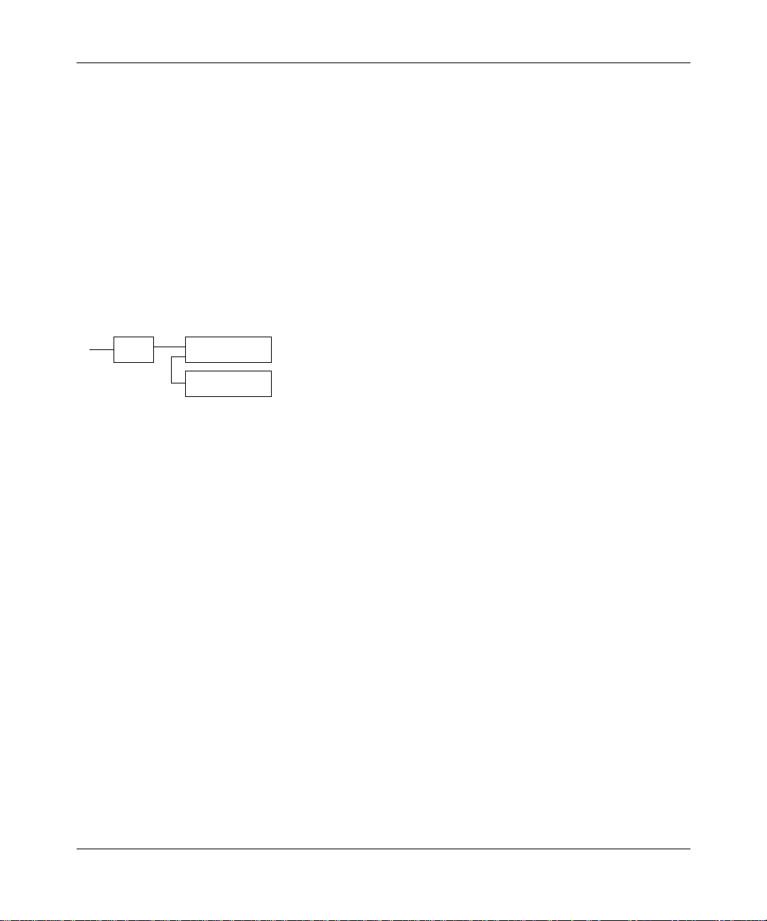
Connecting a Contivity unit containing an ISDN card without NT1
This version of the product is equipped with one standard 8-pin modular jack, labeled ISDN, for connection to the NT1
and one standard 6-pin modular jack, labeled PHONE, for connection to an analog telephone device.
The ISDN card without NT1 is not inte nd e d for dire ct co n nec tio n to the pu blic switched network or other ex p osed p la nt
networks. Always connect the product to such networks through a certified (by the local, regional or national safety
agency and telecommunication s authority), isolating ty pe network t erminating devic e (CSU , LIU, DSU, NT1, NCTE, or
the like) that provides over-voltage protection.
7
U
NT1
Contivity
Branch Access
ISDN Device
9611EB
At the product interface point, the int e rface cable must be wired “straight-through” (pin 1 at one end conn ected to pin 1
at the other end, pin 2 to pi n 2, etc .) , a nd mu st have at le as t the midd le 4 pin s (pins 2, 3, 4, and 5) connected. The cables
included in your package are wired in t hi s fashion.
Your NT1 must be properly connected to your ISDN service; check with your service provider. If you need to add wiring
to your facility , refer to the Natio nal ISDN Users Foru m document NIUF 43 3-94 ISDN Wiring and Powering Guidelines
(Residence and Small B usi ness).
Avis: L'étiquette d'Industrí Canada iden tifie le maté rie l hom o logué . Cett e étiq u ett e certifie q ue le mat ériel es t con fo rme
à certaines normes d e prot ection, d'exp loitat ion et de sécu rité des réseau x de télé commun icatio ns. Toute fois, le M inist ére
n'assure pas que le matériel fonctionnera a la satisfaction de l'utilisateur.
Avant d'installer ce matériel, l'utilisateur doit assurer qu'il soit permis de le raccorder aux installations de l'entreprise
locale de télécommunicatio ns. Le matérie l do it égal eme nt être inst allé en suiva n t une métho d e de raccord eme nt
acceptée. Dans certaíns cas, les fils intérieurs de l'entreprise utilisés pour un service individuel á ligne unique peuvent
être prolongés au moyen d'un dispositif de raccordement homologué (cordon rallonge téléphonique interne). L'abonné
ne doit pas oublier qu'il est possib le que la confo rmité a ux co nditio ns éno ncées ci -dessus n' empechent p as la d égradati on
du service dans cer taines situations. Acluellement, les entreprises de télécommunication ne permettent pas que l'on
raccorde leur matériel à des jacks d'abonn é, sauf dans les cas précis prévus pas les tarrifs particul i ers de ces entreprises.
Les réparations de matériel homologué doivent être effectuées par un centre d'entretien canadien autorisé désigné par le
fournisseur. La compagnie de télécommunications peut demander á l'tilisateur de débrancher un appareil à la suite de
réparations ou de modifications ef fe ct uée s par l'utilisateur, ou à cause de mauva is fonctio nn e men t.
Pour sa propre protection, l 'utilisateur doit assure r que tous l es fils de m ise à la terre d e la sourc e d' énerg ie élect rique, des
lignes téléphoniques et des canalisations d'eau métalliques, s'il y en a, sont raccordés ensemble. Cette précautions est
particuliérement importante dans les régions rurales.
Avertissement: L'utilisateur ne doit pas tenter de faire ces raccordements lui-même; il doit avoir recours aux services
d'un électricien.
Setting Up the Contivity 100 Unit
Page 8

8
L'indice de charge (IC) assigné à chaque dispositif terminal indique, pour éviter toute surcharge, le pourcentage de la
charge totale qui peut être raccordée à un circuit téléphonique bouclé utilisé par ce dispositif. La termination du circuít
bouclé peut être constítuée de n'importe quelle combinaison de dispositifs, pourvu que la somme des indices de charge
de l'ensemble des dispositifs ne dépasse pas 100.
L'indice de charge se trouve sur le modem.
Nortel Networks Inc. software license agreement
NOTICE: Please carefully read this license agreement before copying or using the accompanying software or installing
the hardware unit with pre-enabled software (each of which is referred to as “Software” in this Agreement). BY
COPYING OR USING THE SOFTWARE, YOU ACCEPT ALL OF THE TERMS AND CONDITIONS OF THIS
LICENSE AGREEMENT. THE TERMS EXPRESSED IN THIS AGREEMENT ARE THE ONLY TERMS UNDER
WHICH NORTEL NETWORKS WILL PERMIT YOU TO USE THE SOFTWARE. If you do not accept these terms
and conditions, return the product, unused and in the original shipping container, within 30 days of purchase to obtain a
credit for the full purchase price.
1. License grant. Nortel Networks Inc. (“Nortel Networks”) grants the end user of the Software (“Licensee”) a personal,
nonexclusive, nontransferable license: a) to use the Software either on a single computer or, if applicable, on a single
authorized device identified by host ID, for which it was originally acquired; b) to copy the Software solely for backup
purposes in support of authorized use of the Software; and c) to use and copy th e associated user manual solely in
support of authorized use of the Software by Licensee. This license applies to the Software only and does not extend to
Nortel Networks Agent software or other Nortel Networks software products. Nortel Networks Agent software or other
Nortel Networks software products are licensed for use under the terms of the applicable Nortel Networks Inc. Software
License Agreement that accompanies such software and upon payment by the end user of the applicable license fees for
such software.
2. Restrictions on use; reservation of rights. The Software and user manuals are prot ected under copyright laws.
Nortel Networks and/or its licensors retain all title and ownership in both the Software and user manuals, including any
revisions made by Nortel Networks or its licensors. The copyright notice must be reproduced and inclu ded with any
copy of any portion of the Software or user manuals. Licensee may not modify, translate, decompile, disassemble, use
for any competitive analysis, reverse engineer, distribute, or create derivative works from the Software or user manuals
or any copy, in whole or in part. Except as expressly provided in this Agreement, Licensee may not copy or transfer the
Software or user manuals, in whole or in part. The Software and user manuals embody Nort el Networks’ and its
licensors’ confidential and proprietary intellectual property. Licensee shall not sublicense, assign, or otherwise disclose
to any third party the Software, or any information about the operat ion, design, performance, or implementation of the
Software and user manuals that is confidential to Nortel Networks and its licensors; however, Licensee may grant
permission to its consultants, subcontractors, and agents to use the Software at Licensee’s facility, provided they have
agreed to use the Software only in accordance with the terms of this license.
3. Limited warranty. Nortel Networks warrants each item of Software, as del ivered by Nortel Networks and prop erly
installed and operated on Nortel Networks hardware or other equipment it is originally licensed for, to function
substantially as described i n i ts accompanying user manual during i ts warranty period, which begins on the date
Software is first shipped to Licensee. If any item of Software fails to so function during its warranty period, as the sole
remedy Nortel Networks will at its discretion provide a suitable fix, patch, or workaround for the problem that may be
included in a future Software release. Nortel Networks further warrants to Licensee that the media on which the
Software is provided will be free from defects in materials and workmanship under normal use for a period of 90 days
from the date Software is first shipped to Licensee. Nortel Networks will replace defective media at no charge if it is
returned to Nortel Netwo rks du ring the warranty perio d alon g with p roof of the da te of shi pment. This warr anty do es no t
apply if the media has been damaged as a result of accident, misuse, or abuse. The Licensee assumes all responsibility
for selection of the Software to achieve Licensee’s intended results and for the installation, use, and results obtained
from the Software. Nortel Networks does not warrant a) that the functions contained in the software will meet the
Licensee’s requirements, b) that the Software will operate in the hardware or software combinations that the Licensee
may select, c) that the operatio n of the Software will be un int err up te d or error free, or d) that all defects in the operation
of the Software will be corrected. Nortel Networks is not obligated to remedy any Software defect that cannot be
313369-A
Page 9

reproduced with the latest Software release. These warranties do not apply to the Software if it has been (i) altered,
except by Nortel Networks or in acco rdance with its instructio ns; (ii) use d in conjun ction with anothe r vendo r’s product,
resulting in the defect; or (iii) damaged by improper environment, abuse, misuse, accident, or negligence. THE
FOREGOING WARRANTIES AND LIMITATIONS ARE EXCLUSIVE REMEDIES AND ARE IN LIEU OF ALL
OTHER WARRANTIES EXPRESS OR IMPLIED, INCLUDING WITHOUT LIMITATION ANY WARRANTY OF
MERCHANT ABILIT Y OR FITNESS FOR A PARTICULAR PURPOSE. Licensee is responsible for the security of its
own data and information a nd for maintaini ng adeq uate pro cedures apart from the Software to re cons truct lost or altered
files, data, or programs.
4. Limitation of liability. IN NO EVENT WILL NORTEL NETWORKS OR ITS LICENSORS BE LIABLE FOR
ANY COST OF SUBSTITUTE PROCUREMENT; SPECIAL, INDIRECT, INCIDENTAL, OR CONSEQUENTIAL
DAMAGES; OR ANY DAMAGES RESULTING FROM INACCURATE OR LOST DATA OR LOSS OF USE OR
PROFITS ARISING OUT OF OR IN CONNECTION WITH THE PERFORMANCE OF THE SOFTW ARE, EVEN IF
NORTEL NETWORKS HAS BEEN ADVISED OF THE POSSIBILITY OF SUCH DAMAGES. IN NO EVENT
SHALL THE LIABILITY OF NORTEL NETWORKS RELATING TO THE SOFTWARE OR THIS AGREEMENT
EXCEED THE PRICE PAID TO NORTEL NETWORKS FOR THE SOFTWARE LICENSE.
5. Government licensees. This provision applies to all So ftware an d do cumenta tion ac quired direc tly or i ndirect ly by or
on behalf of the United States Government. The Software and documentation are commercial products, licensed on the
open market at market prices, and were developed entirely at private expense and without the use of any U.S.
Government funds. The license to the U.S. Government is granted only with restricted rights, and use, duplication, or
disclosure by the U.S. Government is subject to the restrictions set forth in subparagraph (c)(1) of the Commercial
Computer Software––Restricted Rights clause of FAR 52.227-19 and the limitations set out in this license for civilian
agencies, and subparagraph (c)(1)(ii) of the Rights in Tec hn ical Data and Computer Software clau se of DFARS
252.227-7013, for agencies of t he Department of Defense or their successors, whichever is applicable.
6. Use of software in the European Community. This provision applies to all Software acquired for use within the
European Community. If Licensee uses the Software within a country in the European Community, the Software
Directive enacted by the Council of Europ ean Communit ies Directive dated 14 May , 19 91, will apply to th e examinati on
of the Software to facilitate interoperability. Licensee agrees to notify Nortel Networks of any such intended
examination of the Soft war e and may procure support and assistance from Nortel Networks.
7. Term and termination. This license is effective until terminated; however, all of the restrictions with respect to
Nortel Networks’ copyright in the Software and user manuals will cease being effective at the date of expiration of the
Nortel Networks copyright; those re strictions relatin g to use and disclosure o f Nortel Networks’ co nfidential information
shall continue in effect. Licensee may terminate this license at any time. The license will automatically terminate if
Licensee fails to comply with any of the terms and conditions of the license. Upon termination for any reason, Licensee
will immediately destroy or return to Nort el Networks the Software, u ser manuals, and all copies. Nort el Networks is not
liable to Licensee for damages in any form solely by reason of the termination of this license.
8. Export and re-export. Licensee agrees not to export, directly or indirectly, the Software or related technical data o r
information without first obtaining any required export licenses or other governmental approvals. Without limiting the
foregoing, Licensee, on behalf of itself a nd its subsidiaries and af filiates, agree s that it will not, without first ob taining all
export licenses and approvals required by the U.S. Government : (i) export, re-export, transfer, or divert any such
Software or technical data, or any direct product thereof, to any country to which such exports or re-exports are restricted
or embargo ed u nder Unite d S ta tes expo rt c ontr ol la ws an d re gula tions, o r to a ny na tion al or re side nt of suc h res tri ct ed or
embargoed coun tries; or (ii) provide the Software or related tech nic a l da ta or in form a tio n to any m ilit ary en d user or for
any military end use, including the design, development, or production of any chemical, nuclear, or biological weapons.
9. General. If any provision of this Agreement is held to be invalid or unenforceable by a court of competent
jurisdiction, the remainder of the prov isions of this Agree ment shall remain in full force and ef fect. Th is Agreement will
be governed by the laws of the state of California.
Should you have any questions concerning this Agreement, contact Nortel Networks Inc., 2375 N. Glenville Dr.,
Richardson, TX 75082.
LICENSEE ACKNOWLEDGES THAT LICENSEE HAS READ THIS AGREEMENT, UNDERSTANDS IT, AND
AGREES TO BE BOUND BY ITS TERMS AND CONDITIONS. LICENSEE FURTHER AGREES THAT THIS
9
Setting Up the Contivity 100 Unit
Page 10

10
AGREEMENT IS THE ENTIRE AND EXCLUSIVE AGREEMENT BETWEEN NORTEL NETWORKS AND
LICENSEE, WHICH SUPERSEDES ALL PRIOR ORAL AND WRITTEN AGREEMENTS AND
COMMUNICATIONS BETWEEN THE PARTIES PERTAINING TO THE SUBJECT MATTER OF THIS
AGREEMENT. NO DIFFERENT OR ADDITIONAL TERMS WILL BE ENFORCEABLE AGAINST NORTEL
NETWORKS UNLESS NORTEL NETWORKS GIVES ITS EXPRESS WRITTEN CONSENT, INCLUDING AN
EXPRESS WAIVER OF THE TERMS OF THIS AGREEMENT.
313369-A
Page 11

Contents
Preface . . . . . . . . . . . . . . . . . . . . . . . . . . . . . . . . . . . . . . . . . . . . . . . . . . . . . . 19
Before you begin . . . . . . . . . . . . . . . . . . . . . . . . . . . . . . . . . . . . . . . . . . . . . . . . . . . . . 19
Acronyms . . . . . . . . . . . . . . . . . . . . . . . . . . . . . . . . . . . . . . . . . . . . . . . . . . . . . . . . . . . 20
Related publications . . . . . . . . . . . . . . . . . . . . . . . . . . . . . . . . . . . . . . . . . . . . . . . . . . .21
How to get help . . . . . . . . . . . . . . . . . . . . . . . . . . . . . . . . . . . . . . . . . . . . . . . . . . . . . . 23
Chapter 1
Introduction . . . . . . . . . . . . . . . . . . . . . . . . . . . . . . . . . . . . . . . . . . . . . . . . . . 25
Contivity 100 package . . . . . . . . . . . . . . . . . . . . . . . . . . . . . . . . . . . . . . . . . . . . . . . . .25
Available options . . . . . . . . . . . . . . . . . . . . . . . . . . . . . . . . . . . . . . . . . . . . . . . . . . . . . 26
Requirements and compatibility . . . . . . . . . . . . . . . . . . . . . . . . . . . . . . . . . . . . . . . . . . 26
Chapter 2
Contivity 100 unit hardware installation . . . . . . . . . . . . . . . . . . . . . . . . . . . 27
11
Getting to know your Contivity 100 unit . . . . . . . . . . . . . . . . . . . . . . . . . . . . . . . . . . . . 27
Interfaces . . . . . . . . . . . . . . . . . . . . . . . . . . . . . . . . . . . . . . . . . . . . . . . . . . . . . . . . 29
Power cords . . . . . . . . . . . . . . . . . . . . . . . . . . . . . . . . . . . . . . . . . . . . . . . . . . . . . . 32
Setting the power voltage selector switch . . . . . . . . . . . . . . . . . . . . . . . . . . . . . . .34
Contivity 100 unit hardware installation . . . . . . . . . . . . . . . . . . . . . . . . . . . . . . . . . . . . 35
Mounting your Contivity 100 unit on a wall . . . . . . . . . . . . . . . . . . . . . . . . . . . . . . . . . . 38
Attaching the brackets to the Contivity 100 unit . . . . . . . . . . . . . . . . . . . . . . . . . .39
Mounting the Contivity 100 unit on a wood wall . . . . . . . . . . . . . . . . . . . . . . . . . . 42
Preparing a wood wall for mounting . . . . . . . . . . . . . . . . . . . . . . . . . . . . . . . . 42
Mounting the Contivity 100 unit on a wood wall . . . . . . . . . . . . . . . . . . . . . . . 42
Mounting the Contivity 100 unit on a drywall or cement wall . . . . . . . . . . . . . . . . . 43
Preparing a drywall or a cement wall for mounting . . . . . . . . . . . . . . . . . . . . . 44
Mounting the Contivity 100 unit on a drywall or cement wall . . . . . . . . . . . . .44
Setting Up the Contivity 100 Unit
Page 12

12 Contents
Chapter 3
Seven-port autosensing Ethernet switch specifications. . . . . . . . . . . . . . 47
Contivity unit 10/100 Ethernet switch overview . . . . . . . . . . . . . . . . . . . . . . . . . . . . . .47
Ethernet switch features . . . . . . . . . . . . . . . . . . . . . . . . . . . . . . . . . . . . . . . . . . . . . . . .48
RJ-45 10BASE-T/100BASE-TX Ethernet ports . . . . . . . . . . . . . . . . . . . . . . . . . . .48
MDI/MDI-X autosensing capability . . . . . . . . . . . . . . . . . . . . . . . . . . . . . . . . . . . .49
LEDs . . . . . . . . . . . . . . . . . . . . . . . . . . . . . . . . . . . . . . . . . . . . . . . . . . . . . . . . . . . 49
Chapter 4
Configuration switch settings . . . . . . . . . . . . . . . . . . . . . . . . . . . . . . . . . . . 51
Configuration switches . . . . . . . . . . . . . . . . . . . . . . . . . . . . . . . . . . . . . . . . . . . . . . . . . 51
Switch settings for normal operation . . . . . . . . . . . . . . . . . . . . . . . . . . . . . . . . . . . 52
Switch settings for the AUX port speed . . . . . . . . . . . . . . . . . . . . . . . . . . . . . . . . .52
Switch settings for special configurations . . . . . . . . . . . . . . . . . . . . . . . . . . . . . . . 53
Resetting your Contivity 100 unit . . . . . . . . . . . . . . . . . . . . . . . . . . . . . . . . . . . . . . . . . 55
Chapter 5
LEDs: support and diagnostic functions. . . . . . . . . . . . . . . . . . . . . . . . . . . 57
313369-A
Interpreting Contivity 100 unit LEDs . . . . . . . . . . . . . . . . . . . . . . . . . . . . . . . . . . . . . . .57
LEDs 1 through 8 and Power LED at power-up sequence . . . . . . . . . . . . . . . . . .58
LEDs 1 through 8 and the Power LED during operation . . . . . . . . . . . . . . . . . . . . 59
Using the seven-port autosensing Ethernet switch LEDs for troubleshooting . . . . 60
Chapter 6
Out-of-band management support. . . . . . . . . . . . . . . . . . . . . . . . . . . . . . . . 61
Configuring the Contivity 100 unit through a direct connection . . . . . . . . . . . . . . . . . . 62
Connecting the Contivity 100 unit directly to a terminal . . . . . . . . . . . . . . . . . . . . .62
Configuring terminal emulation software for a direct connection . . . . . . . . . . . . . .63
Configuring the Contivity 100 unit through a dial-up connection . . . . . . . . . . . . . . . . . 66
Connecting a modem to a PC . . . . . . . . . . . . . . . . . . . . . . . . . . . . . . . . . . . . . . . . 66
Configuring modem connection settings . . . . . . . . . . . . . . . . . . . . . . . . . . . . . . . .67
Connecting a modem to the Contivity 100 unit . . . . . . . . . . . . . . . . . . . . . . . . . . . 70
Connecting to a Contivity 100 unit . . . . . . . . . . . . . . . . . . . . . . . . . . . . . . . . . . . . . . . . 70
Page 13

Contents 13
Appendix A
Technical specifications . . . . . . . . . . . . . . . . . . . . . . . . . . . . . . . . . . . . . . . . 71
Physical specifications . . . . . . . . . . . . . . . . . . . . . . . . . . . . . . . . . . . . . . . . . . . . . . . . . 71
Electrical specifications . . . . . . . . . . . . . . . . . . . . . . . . . . . . . . . . . . . . . . . . . . . . . . . .71
Environmental specifications . . . . . . . . . . . . . . . . . . . . . . . . . . . . . . . . . . . . . . . . . . . . 72
Appendix B
Adapter cable pinout diagrams . . . . . . . . . . . . . . . . . . . . . . . . . . . . . . . . . . 73
Remote access adapter cables . . . . . . . . . . . . . . . . . . . . . . . . . . . . . . . . . . . . . . . . . .73
Null modem adapter (PC-to-PC) cable . . . . . . . . . . . . . . . . . . . . . . . . . . . . . . . . .73
Modem adapter cable . . . . . . . . . . . . . . . . . . . . . . . . . . . . . . . . . . . . . . . . . . . . . .74
Index . . . . . . . . . . . . . . . . . . . . . . . . . . . . . . . . . . . . . . . . . . . . . . . . . . . . . . . . 75
Setting Up the Contivity 100 Unit
Page 14

14 Contents
313369-A
Page 15

Figures
Figure 1 Front panel of the Contivity 100 unit . . . . . . . . . . . . . . . . . . . . . . . . . . . . . 28
Figure 2 Rear panel of the Contivity 100 unit . . . . . . . . . . . . . . . . . . . . . . . . . . . . .29
Figure 3 Components for mounting the Contivity 100 unit on a wall . . . . . . . . . . . . 39
Figure 4 Removing screws from the cover of the Contivity 100 unit . . . . . . . . . . . .40
Figure 5 Attaching the mounting bracket to the Contivity 100 unit . . . . . . . . . . . . . 41
Figure 6 Mounting the Contivity 100 unit on the wall . . . . . . . . . . . . . . . . . . . . . . . 43
Figure 7 Configuration switches on the rear panel of the unit . . . . . . . . . . . . . . . .51
Figure 8 Contivity 100 unit LEDs . . . . . . . . . . . . . . . . . . . . . . . . . . . . . . . . . . . . . .58
Figure 9 HyperTerminal Connection Description dialog box . . . . . . . . . . . . . . . . . .64
Figure 10 HyperTerminal Connect To dialog box . . . . . . . . . . . . . . . . . . . . . . . . . . . 64
Figure 11 HyperTerminal COM1 Properties dialog box . . . . . . . . . . . . . . . . . . . . . . 65
Figure 12 Command prompt . . . . . . . . . . . . . . . . . . . . . . . . . . . . . . . . . . . . . . . . . . .66
Figure 13 HyperTerminal Connection Description dialog box . . . . . . . . . . . . . . . . . . 67
Figure 14 HyperTerminal Connect To dialog box . . . . . . . . . . . . . . . . . . . . . . . . . . . 68
Figure 15 HyperTerminal COM1 Properties dialog box . . . . . . . . . . . . . . . . . . . . . .69
Figure 16 Null modem adapter cable pinout diagram . . . . . . . . . . . . . . . . . . . . . . . .74
Figure 17 Modem adapter cable pinout diagram . . . . . . . . . . . . . . . . . . . . . . . . . . . 74
15
Setting Up the Contivity 100 Unit
Page 16

16 Figures
313369-A
Page 17

Tables
Table 1 Ethernet interfaces . . . . . . . . . . . . . . . . . . . . . . . . . . . . . . . . . . . . . . . . . 30
Table 2 Communications interface cards . . . . . . . . . . . . . . . . . . . . . . . . . . . . . . . 30
Table 3 International power cord specifications . . . . . . . . . . . . . . . . . . . . . . . . . . 32
Table 4 Voltage selector switch settings . . . . . . . . . . . . . . . . . . . . . . . . . . . . . . . . 34
Table 5 Switch settings for normal operation . . . . . . . . . . . . . . . . . . . . . . . . . . . . 52
Table 6 Switch settings for setting the AUX port speed to 9600 baud . . . . . . . . .52
Table 7 Switch settings for resetting the passwords . . . . . . . . . . . . . . . . . . . . . . . 53
Table 8 Switch settings for resetting the passwords and user-defined
Table 9 Switch settings to disable switch settings for resetting the
Table 10 Switch settings for resetting factory default conditions . . . . . . . . . . . . . . .54
Table 11 LED status and appearance during operation . . . . . . . . . . . . . . . . . . . . .59
Table 12 Ethernet switch port status LEDs . . . . . . . . . . . . . . . . . . . . . . . . . . . . . . .60
17
configurations . . . . . . . . . . . . . . . . . . . . . . . . . . . . . . . . . . . . . . . . . . . . . . 53
passwords and user-defined configurations . . . . . . . . . . . . . . . . . . . . . . . 54
Setting Up the Contivity 100 Unit
Page 18

18 Figures
313369-A
Page 19
Preface
This manual describes the Contivity* 100 unit and what you do to install the
Contivity 100 unit hardware.
Before you begin
19
Warning:
open the Contivity 100 unit. There are no user-serviceable components
inside.
Before using this manual, you need to do two things. First, write down the model
number and serial number of your Contivity 100 unit. You will need this
information if you call Nortel Networks* Technical Support. Model and serial
numbers are located on the rear panel of your unit.
Model # ____________________________________________________
Example: DM1401E67
Serial # ____________________________________________________
Example: I500E07BF224BB
Second, you must obtain Internet access from an Internet service provider (ISP).
For details, refer to I nst al li ng the Conti vit y Branch Access Management Software
Version 7.20.
Note: Do not apply power to the unit until you have completed the
installation ste ps in Chapter 2, “Contivity 100 unit hardware inst alla tion,”
on page 35.
To avoid bodily injury from hazardous electrical shock, never
Setting Up the Contivity 100 Unit
Page 20

20 Preface
Acronyms
The following acronyms are used in this manual:
AC Alternating Current
CEE Certification of Electrical Equipment
CENELEC European Committee for Electrotechnical Standardization
CLI Command Line Interface
CSA Canadian Standards Associates
CSU Channel Service Unit
cUL Underwriter Laboratories testing to Canadian standards
dBA Decibels Audible
DIP Dual Inline Pins
DMZ Demilitarized Zon e
DSU Data Service Unit
FDX Full Duplex
HAR Harmonized
HD Harmonized Document
HDX Half Duplex
IEC International Electrotechnical Commission
ISDN Integrated Services Digital Network
ISP Internet Service Provider
Kb/s Kilobits Per Second
LAN Local Area Network
LED Ligh t-Emitti ng Di od e
LIU Line Is olation Un it
MB Megabyte
Mb/s Megabits Per Second
MDI Medium Dependent Interface
MDI-X Medium Dependent Interface - Crossover
MP Multilink Pr otocol
NCTE Network Channel Terminating Equipment
NEMA National Electrical Manufacturers Association
313369-A
Page 21

Preface 21
NIC Network Interface Card
NIUF National ISDN Users Forum
NOM Norma Oficial Mexicana
NT1 Network Termination Type 1
PC Personal Computer
POTS Plain Old Telephone Service
PPP Point-to-Point Protocol
PPPoE Point-to-Point Protocol over Ethernet
STP Shielded Twisted-Pair
TUV Technischer Üeberwachungs Verein
UL Underwriter Laboratories
URL Uniform Resource Locator
UTP Unshielded Twisted Pair
VAC Voltage Alternating Current
WAN Wide Area Ne twork
Related publications
For more infor mat ion ab out us ing Conti vity Bran ch Acce ss, refe r to t he fol low ing
publications:
• Important N otice for the Contivity Br anch Access Version 7.20
(part number 313368-A)
Provides instructions for viewing documentation and installing the Contivity
Branch Access management software and third-party applications (Adobe*
Acrobat Reader*, Netscape Communicat or*, and Ani Ta Te rminal Emulat or*).
• Installing the Contivity Branch Access Management Software Version 7.20
(part number 313367-A)
Provides instructions for installing the Contivity Branch Access management
software.
Setting Up the Contivity 100 Unit
Page 22

22 Preface
• Using the Contivity Branch Access Management Software Version 7.20
(part number 313371-A)
Provides an introduction to Contivity Branch Access, instructions for
administering the product, and procedures for using software features.
• Reference for the Contivity Branch Access Command Line Interface Version
7.20 (part number 313372-A)
Provides instructions and CLI commands for remotely accessing the
Contivity unit and for administering the unit using out-of-band management.
• Contivity Branch Access Software and Documentation Version 7.20 CD
(part number 313374-A)
Provides manuals for using and installing the Contivity Branch Access
management software and third-party applications. The CD contains the
following documents:
— Installing the Contivity Branch Access Management Software Version
7.20
— Setting Up the Contivity 100 Unit
— Setting Up the Contivity 400 Unit
— Using the Contivity Branch Access Management Software Version 7.20
— Reference for the Contivity Branch Access Command Line Interface
Version 7.20
313369-A
You can print selected technical manuals and release notes free, directly from the
Internet. Go to the www.nortelnetworks.com/documentation URL. Find the
product for which you n eed documentation. Then locat e the specific categor y an d
model or version for your hardware or software product. Use Adobe Acrobat
Reader to open the manuals and release notes, search for the sections you need,
and print them on most standard printers. Go to Adobe Systems at the
www.adobe.com URL to download a free copy of the Adobe Acrobat Reader.
You can purchase selected documentation sets, CDs, and technical publications
through the Internet at the www1.fatbrain.com/documentation/nortel URL.
Page 23

How to get help
If you purchased a service contract for your Nortel Networks product from a
distributor or authorized reseller, contact the technical support staff for that
distributor or reseller for assistance.
If you purchased a Nortel Networks service program, cont act one of the fol lowing
Nortel Networks Technical Solutions Centers:
Technical Solutions Center Telephone
Europe, Middle East, and Africa (33) (4) 92-966-968
North America (800) 4NORTEL or (800) 466-7835
Asia Pacific (61) (2) 9927-8800
China (800) 810-5000
An Express Routing Code (ERC) i s av ail ab le f or many Nor te l Ne twor ks products
and services. When you use an ERC, your call is routed to a technical support
person who specialize s in suppor ting tha t product or service. To locate an ERC for
your product or service, go to the www.nortelnetworks.com/servsup URL. Click
the Tools menu item and then click Express Routing Codes under the Other
heading.
Preface 23
Setting Up the Contivity 100 Unit
Page 24

24 Preface
313369-A
Page 25
Chapter 1
Introduction
This chapter introduces your Contivity 100 unit and describes package contents,
available options for your unit, and any requirements and compatibility issues.
25
Caution:
selector switch setting matches your power voltage. For details, refer to
“Setting the power voltage selector switch” on page 34.
Warning:
open the Contivity 100 unit. There are no user-serviceable components
inside.
Before you install your unit, make sure that the power voltage
To avoid bodily injury from hazardous electrical shock, never
Contivity 100 package
The Contivity 100 package contains:
• Contivity 100 unit
• Important N otice for the Contivity Br anch Access Version 7.20
(part number 313368-A)
• Installing the Contivity Branch Access Management Software Version 7.20
(part number 313367-A)
• Contivity Branch Access Software and Documentation Version 7.20 CD
(part number 313374-A)
For contents, see “Related publications” on page 21.
• Depending on the type of connection you ordered, your Contivity 100
package contains one or more of the following connector cables:
— RJ-11 cable (phone cord) for a dial-up connection
— ISDN cable for an Integrated Service Digital Network (ISDN) connection
Setting Up the Contivity 100 Unit
Page 26

26 Chapter 1 Introduction
— RJ-45 straight-through cable (gray) for a 10BASE-T or 100BASE-T
Ethernet* connection
— RJ-45 crossover cable (red) for a 10BASE-T or 100BASE-T Ethernet
connection
Available options
The Contivity 100 unit is shipped with a seven-port autosensing, autonegotiating
10/100 Ethernet switch on the front of the unit, a full-duplex/half-duplex
autonegotiating 10/100 megabits per second (Mb/s) Ethernet connection on the
rear of the unit, and one of the following:
• A third Ethernet connection
• Internal single- or dual-analog modem
• Internal ISDN 128K card (with or without NT1) with a Plain Old Telephone
Service (POTS) connection
Requirements and compatibility
Your Contivity 100 unit supports the following Internet connection types:
• Dial-up Point-to-Point Protocol (PPP) connection with optional Multilink
Protocol (MP) at up to two times V.90
• ISDN connection using synchronous PPP and optional Multilink Protocol
(MP) at up to 128 kilobits per second (Kb/s)
• Point-to-Point Protocol over Ethernet (PPPoE) connection using an external
Ethernet device to connect to an access concentrator
Note: The speed of dial-up connections can vary internationally.
Consult your local distributor for specifications.
313369-A
Page 27

Chapter 2
Contivity 100 unit hardware installation
This chapter helps you get to know your Contivity 100 unit, and provides
instructions for conn ecting your unit to your LAN and WAN accordi ng to the type
of connection you are using, and for mounting your unit on a wall.
Before you install your Contivity 100 unit hardware, make sure that you are
familiar with the physical and environmental specifications of the unit. For more
information, refer to Appendix A, “Technical specifications,” on page 71.
27
Caution:
selector switch setting matches your power voltage. For more
information, see “Setting the power voltage selector switch” on page 34.
Warning:
open the Contivity 100 unit. There are no user-serviceable components
inside.
Before you install your unit, make sure that the power voltage
To avoid bodily injury from hazardous electrical shock, never
Getting to know your Contivity 100 unit
The front panel of your Contivity 100 unit has the following indicators and
connections:
• Nine LEDs (labeled 1–8 and Power) indicate various active or error
conditions for your unit. For details, refer to Chapter 5, “LEDs: support and
diagnostic functions,” on page 57.
Setting Up the Contivity 100 Unit
Page 28

28 Chapter 2 Contivity 100 unit hardware instal la tio n
• A seven-port autosensing, autonegotiating Ethernet switch provides a means
for connecting to your net work and enabl es you to elim inate an ex tra Ethern et
switch or hub on your LAN. Each por t adapts to th e correct network speed (1 0
Mb/s or 100 Mb/s), the duplex mode of the connected device, and the correct
MDI status of the cable. For d etails, refer to Chapter 3, “Seven-port
autosensing Ethernet switch specifications,” on page 47.
• Seven 10/100 Link/Activity LEDs (labeled S1–S7) display port status for the
Ethernet switch. For details, refer to Chapter 5, “LEDs: support and
diagnostic functions,” on page 57.
• Seven FDX LEDs (labeled S1–S7) display port mode status for the Ethernet
switch. For details, refer to Chapter 5, “LEDs: support and diagnostic
functions,” on page 57.
Figure 1 illustrates the front panel of the unit.
Figure 1
Front panel of the Contivity 100 unit
12345678
Power
10/100 Link/Activity
HDX/FDX
S2 S3 S4 S5 S6 S7
S1
S1 S2 S3 S4 S5 S6 S7
Contivity
100
9861EB
The rear panel of the unit contains the following switches and connectors:
• A communications int erface (one or two phone jac ks, an ISDN jack, or a third
Ethernet connection) for connecting to your telephone service company
(telco), external Ethernet connection, or ISP
• Second full-duple x/half- duplex aut onegotiat ing Ether net connect ion (Eth2 ) to
connect to a router or bridge to support a Demilitarized Zone (DMZ), or to
add another network segment
• AUX port to directly connect a PC or modem for out-of-band management
(see Chapter 6, “Out-of-band management support,” on page 61)
• Configuration switch es (se e Chapter 4, “Configuration switch settings,” on
page 51)
• Power voltage selector switch (115 or 230 VAC)
• Power supply connector and power switch
313369-A
Page 29

Chapter 2 Contivity 100 unit hardware installation 29
Figure 2 illustrates the rear panel of the unit.
Figure 2
Eth2 connection
(to router
or bridge)
Rear panel of the Contivity 100 unit
Ethernet device)
Link Act
Ethernet
10/100
or modem)
Note:
(Eth3) replaces the phone jack or ISDN jack at the top of the unit.
Warning:
danger of explosion if the battery is replaced incorrectly. The battery
should be replaced only by factory authorized personnel.
Option card
(to telco or
Aux Configure
Configuration
AUX port
(to PC
switches
Power
switch
115 / 230 V ~
50 / 60 Hz , 4A / 2A
Power supply
connector
Power voltage
selector switch
Fan
If you have a triple-Ethernet unit, the third Ethernet connection
Y our Contivity 100 u nit contains a lithium batte ry . Th ere is a
230VAC
115VAC
9859EC
Interfaces
Each unit has an autosensing, autonegotiating seven-port 10/100 Ethernet switch,
a full-duplex/half-duplex autonegotiating Ethernet LAN interface, and one of
several communications interface cards.
Note: The interf ace card( s) in your uni t may no t look exa ctly like t hose
depicted in the illustrations.
Setting Up the Contivity 100 Unit
Page 30

30 Chapter 2 Contivity 100 unit hardware instal la tio n
Table 1 describes the Ethernet interfaces available for your Contivity 100 unit.
Table 1
Ethernet interfaces
Interface name Interface card Type
Eth1 Seven-port Ethernet switch on
the front of the unit. Use Eth1
as your LAN connection.
More information is availabl e in
9865EB
Chapter 3, “Seven-port
autosensing Ethernet swit ch
specifications,” on page 47.
Eth2 Standard Ethernet interface on
Link Act
the back of the unit. Use Eth2
as your DMZ connection.
Ethernet
10/100
Aux
Configuration
9935EC
Eth3 Optional Ethernet interface
card. Use Eth3 as your WAN
ALM
100
10
connection.
9855EB
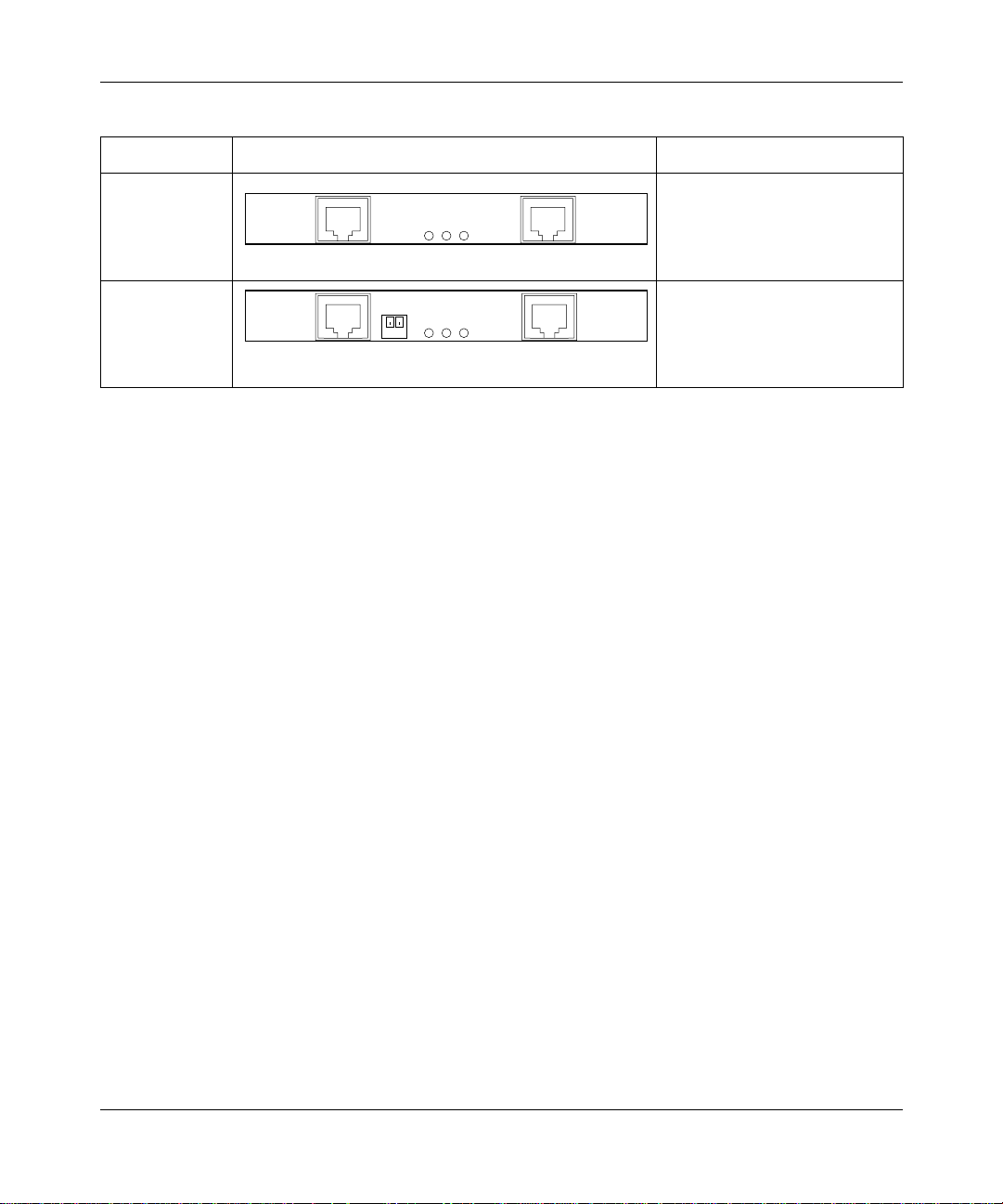
Table 2 describes the communications inter face cards avail able for y our Cont ivit y
100 unit.
Table 2
Communications interface cards
Interface name Interface card Type
Analog Analog modem interface card
LinePhone
with one RJ-11 connector for
the phone (outgoing to mo dem)
and one RJ-1 1 c onnector for the
9858EB
telco (incoming from wall jack).
Dual Analog Analog modem interface card
with two RJ-11 connectors for
Line
Phone
Line
Phone
phones (outgoing to modem)
and two RJ-11 connectors for
9857EC
telcos (incoming from wall jack).
313369-A
Page 31
Chapter 2 Contivity 100 unit hardware installation 31
Table 2
Communications interface cards (continued)
Interface name Interface card Type
ISDN U ISDN U interface card
(integrated NT1) with one
ISDN
B1B2LK
Phone
POTS connector and one RJ-4 5
connector .
9856ED
ISDN S/T ISDN interface card (no
ISDN
1 2
TR
B1B2LK
Phone
10047EC
integrated NT1) with one POTS
connector and one RJ-45
connector.
Setting Up the Contivity 100 Unit
Page 32
32 Chapter 2 Contivity 100 unit hardware instal la tio n
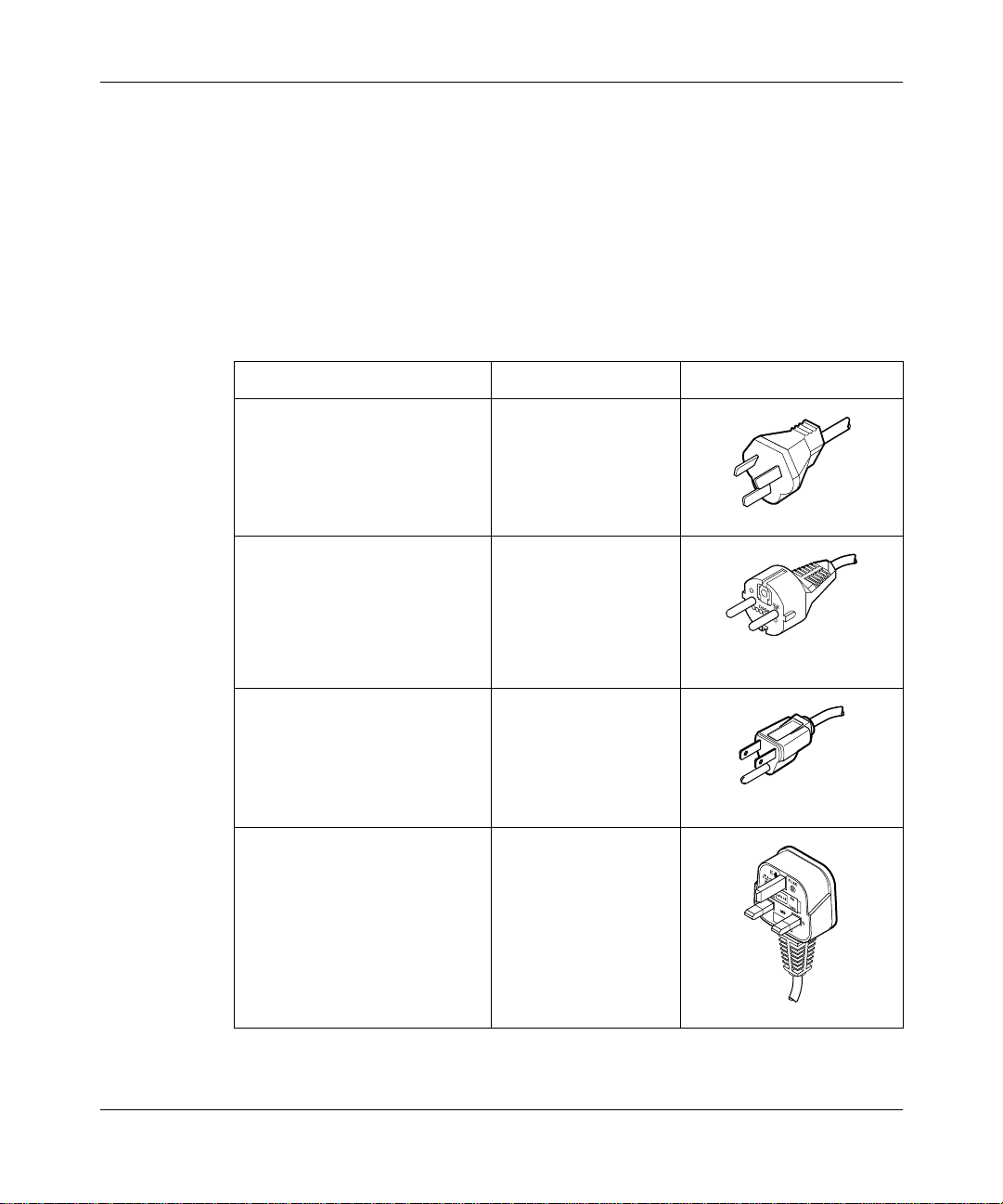
Power cords
The AC power receptacle accepts the AC power cord (supplied). For installation
outside of North America, make sure th at you have the proper power cord for your
region. Any cord used must have a CEE-22 standard V female connector on one
end and must meet the IEC 320-030 specifications.
Table 3 lists specifications for international power cords.
Table 3
Country/Plug description Specifications Typical plug
Australia:
• AS3112-1981 Male plug
Continental Europ e:
• CEE7 standard VII male plug
• Harmonized cord (HAR
US/Canada/Japan:
• NEMA5-15P male plug
• UL recognized (UL stam ped
• CSA certified (CSA label
United Kingdom:
• BS1363 male plug with fuse
• Harmonized cord (HAR
International power cord specifications
240 VAC
50 Hz
Single phase
220 or 230 VAC
50 Hz
Single phase
marking on the outside of the
cord jacket to comply with the
CENELEC Harmonized
Document HD-21)
100 or 120 VAC
50–60 Hz
Single phase
on cord jacket)
secured to the cord)
240 VAC
50 Hz
Single phase
marking on the outside of the
cord jacket to comply with the
CENELEC Harmonized
Document HD-21)
230FA
228FA
227FA
313369-A
229FA
Page 33

Chapter 2 Contivity 100 unit hardware installation 33
Caution: Please read immediately.
Inspect this power cord and de termine if it provides the proper plug an d is
appropriately certified for use with your electrical system. Immediately
discard this cord if it is inappropriate for your country’s electrical system
and obtain the prope r c ord as requi red by your n ationa l ele ctri cal c odes or
ordinances.
Refer to this product’s technical documentation for detailed installation
procedures to be followed by qualified service personnel.
Achtung: Bitte sofort lesen.
Sehen Sie nach, ob dieses Netzkabel über den richtigen Stecker verfügt
und für die Verwendung in Ihrem Stromversogungsnetz zertifiziert ist.
Falls dieses Kabel nicht für das Stromversorgungsnetz in Ihrem Land
geeignet ist, darf es nicht verwende t werden. Be sorg en Sie sich ein Kabel,
das die Vorschriften der Zulassungsbehörden in Ihrem Land erfüllt.
Die technische Dokumentation dieses Produkts enthält ausführliche
Installationsanweisungen, die nur von qualifiziertem
Kundendienstpersonal ausgeführt werden dürfen.
Attention: Lisez ceci immédiatement.
Examinez ce cordon d'alimentation pour déterminer s'il dispose de la
fiche appropriée et s'il est bien agré é pour uti lisat ion sur votr e insta llat ion
électrique. Débarrassez-vous en immédiatement s'il ne convient pas à
l'utilisation sur le secteur électrique en usage dans votre pays et
procurez-vous un cordon conforme à la réglementation nationale en
vigueur.
Reportez-vous à la documentation technique de ce produit pour obtenir
des instructions d étail lées d'ins tall ation , destin ées à un te chnici en qual ifi é.
Attenzione: Leggere attentamente.
Controllare questo cav o di ali mentazi one, ver ific arne il col lega mento con
la presa appropriata nonché la certificazione per l'uso nell'impianto
elettrico posseduto. Non utili zzare assolut amente in caso tale cavo non sia
adatto al sis tema elet trico d el paese in c ui viene utiliz zato e richiede rne un
altro certificato dall'ente nazionale di fornitu ra elettrica .
Per le procedure di installazione che devono essere seguite dal personale
di servizio, consultare questa documentazione tecnica del prodotto.
Setting Up the Contivity 100 Unit
Page 34
34 Chapter 2 Contivity 100 unit hardware instal la tio n
Precaución: Sírvase leer inmediatamente.
Inspeccione este cable de alimentación eléctrica y determine si viene con
el enchufe apropiado y está debidamente certificado para el uso con su
sistema elé ctrico. Si no cumple con los reglamentos del sistema eléctric o
de su país, despójese de este cable de alimentación inmediatamente y
obtenga el cable requerido, según las ordenanzas y códigos eléctricos
nacionales.
Refiérase a la documentación técnica de este producto para recibir
información detallada sobre los pro cedimie ntos que el perso nal calific ado
de reparaciones deberá seguir.
313369-A
Setting the power voltage selector switch
The voltage of the Cont ivit y 100 uni t must matc h the v oltag e of t he p ower sou rce.
If you set the switch to 110 and the voltage that the unit is connecting to is
200 VAC or above, you must return the unit for repai r. If you set the switch to 230
and the voltage that the unit is connecting to is 127 VAC or below, the unit may
not function properly.
Table 4 shows the voltage selector switch settings for the two voltage ranges.
Table 4
Setting Voltage range
115 For voltages between 100 and 127 VAC
230 For voltages between 200 and 240 VAC
Voltage selector switch settings
Page 35
Chapter 2 Contivity 100 unit hardware installation 35
To set the voltage selector switch:
Use a small instrument with a fine point, such as the tip of a pen or a
straightened paper c lip, to move the swit ch to the proper s etting (se e Figure 2
on page 29).
Contivity 100 unit hardware installation
These steps guide you thro ugh the general process of ins talling your Cont ivity 100
unit hardware.
Install your Contivit y 100 unit in a ventilated area that is dust fr ee and away from
heat vents, warm air exhaust from other equipment, and direct sunlight. Avoid
proximity to large electric motors or other electromagnetic equipment. Be sure to
choose a location near your router and LAN or WAN hubs and close to an
electrical outlet.
Caution:
voltage selector switch matches your power voltage (see “Setting the
power voltage select or swi tch” o n page 34) and the configuration switch
settings are set to normal operation (see “Switch settings for normal
operation” on page 52).
Warning:
never open the Contivity 100 unit. There are no user-serviceable
components inside.
The communications connection is necessary to provide the link between your
unit and your Internet ser vi ce pr ovi der (ISP). To ensure a proper communications
connection, make sure that you have ordered the appropriate following services:
• Installation from your telco
• Service from your telco
• Internet access service from your ISP
Before you begin installation, make sure that the power
To avoid bodily injury from hazardous electrical shock,
Setting Up the Contivity 100 Unit
Page 36

36 Chapter 2 Contivity 100 unit hardware instal la tio n
For more information, refer to Installing the Contivity Branch Access
Management Software Version 7.20.
Note:
Do not apply power to the unit until you have completed the
installation steps.
You can mount your Contivity 100 unit on a wall or place it on a flat surface. If
you choose to place the unit on a flat surface, be sure to install the unit’s rubber
feet. If the feet are not already installed, stick the adhesive side of the feet on the
spaces provided on the bottom of the unit. You must use either the mounting
brackets or the feet.
To install your Contivity 100 unit hardware:
1
Do one of the following:
• If you want to mount your Contivity 100 unit on a wall, you must do so
before you connect it to your LAN. Follow the procedure “Mounting your
Contivity 100 unit on a wall” on page 38 and then return to this procedure
and continue with step2.
• If you do not want to mount your Contivity 100 unit on a wall, place the
unit on any appropriately level surface that can safely support the weight
of the unit and attached cables. Make sure that there is adequate space
around the unit for ventilation and access to cable connectors. Allow at
least 2 inches (5.1cm) on each side for proper ventilation and 5 inches
(12.7cm) at the back for power cord clearance and ventilation. Continue
with step 2.
313369-A
2
With the tip of a pen, slide the power voltage selector switch to the power
voltage setting that matches your power voltage. For more information, see
“Setting the power voltage selector switch” on page 34.
3
Attach one end of the communications cable (analog modem, ISDN, cable
modem, or Ethernet connection to a router or bridge) to the appropriate
connector on the rear panel of the unit (Figure 2 on page 29).
• If you are using an ext ernal Ethe rnet devic e, use the Ether net connect or in
the option slot (Eth3) to con nect to the external device. Be sur e to use the
proper cable (straight-through or crossover) for this connection.
Note: Use the second Ethernet connection (Eth2) to connect a DMZ or
to connect two LANs together.
Page 37

Chapter 2 Contivity 100 unit hardware installation 37
4
Attach the other end of the communications cable to the appropriate source
(phone jack, ISDN jack, cable modem, or other external device).
5
Do one of the following:
• To use the Contivity 100 unit as your LAN switch, attach up to seven
workstations to t h e se ven -po rt s wit ch (Et h1) on the front panel o f the u nit .
• To connect the Contivity 100 unit to your LAN, attach one end of the
LAN cable (straight-through or crossover) to one of the ports on the
seven-port switch (Eth1) and attach the other end of the cable to your
LAN.
6
Plug the power cord into the rear panel of the unit.
7
Plug the power cord into an AC wall outlet.
8
Turn on the unit.
When you turn on your Contivity 100 unit, LEDs 1 through 8 and the Power
LED illuminate. LED 2 glows amber when the unit is ready for configurat i on.
Note:
Note:
You may have to wait several minutes for LED 2 to glow amber.
If all LEDs glow amber, or none of the LEDs illuminates, check
that the power voltage selector switch setting matches your power
voltage. For more information, see “Setting the power voltage selector
switch” on page 34.
9
Configure the unit.
For information about configuring your unit, see Installing the Contivity Branch
Access Management Software Version 7.20.
Setting Up the Contivity 100 Unit
Page 38
38 Chapter 2 Contivity 100 unit hardware instal la tio n
Mounting your Contivity 100 unit on a wall
You can mount the Contivity 100 unit on any drywall, wood, or cement wall that
is at least 0.39 inches (10 mm) thick and is capable of supporting the combined
weight of the unit and attached cables (approximately 11 pounds or 5 kg).
A set of brackets, self-tapping (3.5x16) drywall screws, and (3x18) plastic
expansion lugs (Figure 3) has been included wit h t he Cont ivi ty 100 unit. You will
also need a pencil and a Phillips screwdriver, which are not included with t he unit.
Caution:
the weight of the device, plus the additional weight of the attached
network cables and power cords.
Achtung:
Gewicht des Geräts, zuzüglich des Gewichts der angeschlossenen
Netzwerk- und Netzstromkabel, standhalten können.
Attention:
supporter le poids du dispositif, ainsi que des câbles réseau et cordons
qui y sont rattachés.
Attenzione:
sostenere il peso del dispositivo, oltre a quello dei cavi di rete e di
alimentazione collegati.
Precaución:
capaces de sostener el peso del dispositivo más el peso adicio nal de los
cables de red y cables de alimentación conectados.
The screws and wall composition must be able to withstand
Schrauben und Wand müssen so beschaffen s ein, daß sie dem
Les vis de fixation et le mur doivent être capables de
Le viti e la struttura a muro devono essere in grado di
Los tornillos y la composición de la pared deben ser
313369-A
Page 39
A
Chapter 2 Contivity 100 unit hardware installation 39
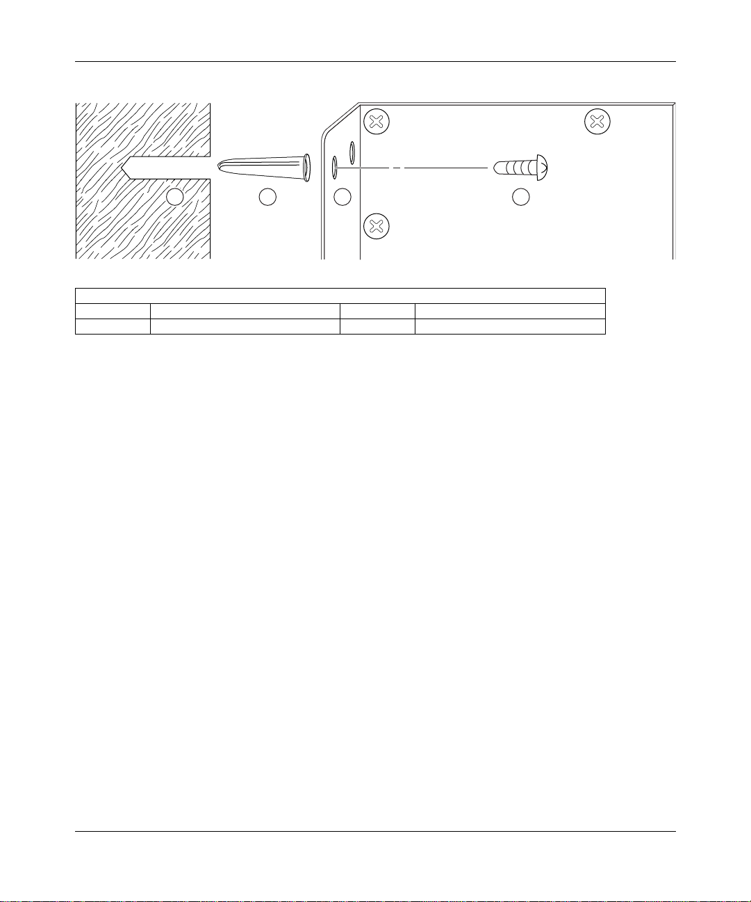
Figure 3
LEGEND
1 Hole drilled in the wall 3 Wall mounting bracket
2 Plastic expansion lug 4 Self-tapping drywall screw or #6 wood screw
Components for mounting the Contivity 100 unit on a wall
1
2 3 4
Attaching the brackets to the Contivity 100 unit
Before you begin mounting the uni t on a wal l, you must at tach the brackets to the
unit.
To attach the brackets to the Contivity 100 unit:
10095E
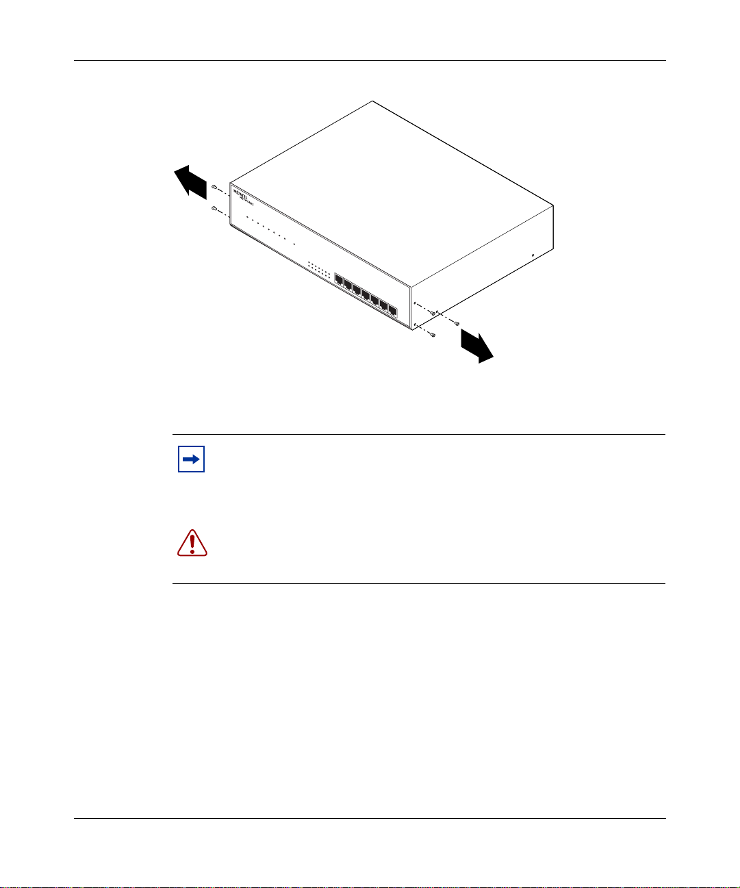
1
Remove the three screws from the c over o n each side of y our un it as shown in
Figure 4.
Setting Up the Contivity 100 Unit
Page 40
40 Chapter 2 Contivity 100 unit hardware instal la tio n
Figure 4
2
Removing screws from the cover of the Contivity 100 unit
12345678
Power
10/100 Link/Activity
HDX/FDX
Contivity
100
9873FC
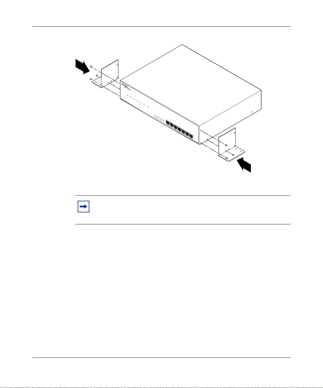
Attach the mounting brackets to your unit with the screws provided in the
wall mount kit included with your unit (Figure 5).
Note:
The wall mount kit contains six screws with attached washers and
may contain four screws without washers. Use the screws with attached
washers to attach the mounting brackets to your unit (three screws on
each side). You can discard the four screws without washers.
313369-A
Warning:
To avoid bodily injury from hazardous electrical shock, never
open the Contivity 100 unit. There are no user-serviceable components
inside.
Page 41
Chapter 2 Contivity 100 unit hardware installation 41
Figure 5
Note:
unit. Only three of the six holes in the mounting bracket are used on each
side of the unit.
Attaching the mounting bracket to the Contivity 100 unit
12345678
Power
10/100 Link/Activity
HDX/FDX
Contivity
100
10285FA
Each mounting bracket is designed to work on either side of the
3
Do one of the following:
• T o mount the unit on a woo d wall, con tinue with “Mounting the Contivity
100 unit on a wood wall” next.
• To mount the unit on a drywall or a cement wall, continue with
“Mounting the Contivity 100 unit on a drywall or cement wall” on
page 44.
Setting Up the Contivity 100 Unit
Page 42

42 Chapter 2 Contivity 100 unit hardware instal la tio n
Mounting the Contivity 100 unit on a wood wall
To mount the Contivity 100 unit on a wood wall, you need a #6 wood screw (not
included) that is long enough to penetrate the wood by at least 1/2-inch.
Mounting the unit on a wood wall is a two-part process. You will:
1
Prepare the wood wall for mounting.
2
Mount the unit on the wall.
Note:
to the unit. See “Attaching the brackets to the Contivity 100 unit” on
page 39.
Before you mount the unit on a wall, you must attach the brackets
Preparing a wood wall for mounting
To prepare a wood wall for mounting, you will use a pencil to mark where the
brackets should be placed on the wall. Marking the wall makes mounting easier
because you limit the amount of time necessary to maneuver with the weight of
the unit in your hands and you ensure the accuracy of where the holes are placed.
To mark where the brackets should be placed on the wall:
1
Place your unit with attached brackets against the wall where you want to
mount the unit.
2
Use a pencil to mark where the holes should be placed in the wall for each
bracket.
After you mark the wall, you can mount the unit on the wall (next).
Mounting the Contivity 100 unit on a wood wall
313369-A
You will attach one bracket at a time to the wall.
To mount the Contivity 100 unit on a prepared wood wall:
1 Align the holes in the attached bracket with the marks on the wall.
Page 43

Chapter 2 Contivity 100 unit hardware installation 43
2
Insert each of the four screws through the holes in the bracket and into the
wood wall (Figure 6). Use only wood screws.
Figure 6
3
Mounting the Contivity 100 unit on the wall
Screw in the screws.
12345678
10/100 Link/Activity
HDX/FDX
Power On
Contivity
100
9864FC
4
Repeat steps 1–3 to attach the other mounting brack et to the wall.
Mounting the Contivity 100 unit on a drywall or cement wall
T o moun t the Cont ivity 100 uni t on a dry wall or cement wal l, you need a dr ill and
a 1/4-inch drill bit (not included).
Mounting the unit on a drywall or cement wall, is a two-part process. You will:
1 Prepare a drywall or cement wall for mounting.
Setting Up the Contivity 100 Unit
Page 44

44 Chapter 2 Contivity 100 unit hardware instal la tio n
2
Mount the unit on the wall.
Note:
Before you mount the unit on a wall, you must attach the brackets
to the unit. See “Attaching the brackets to the Contivity 100 unit” on
page 39.
Preparing a drywall or a cement wall for mounting
To prepare a drywall or cement wall for mounting, you will use a pencil to mark
where the brackets should be placed on the wall. Marking the wall makes
mounting easier becaus e you limit the amount of time nec essary to maneuver wit h
the weight of the unit in your hands and you ensure the accuracy of where the
holes are placed.
To prepare a drywall or a cement wall for mounting:
1
Place your unit with attached brackets against the wall where you want to
mount the unit.
2
Use a pencil to mark where the holes should be drilled in the wall for each
bracket.
3
Remove your unit from against the wall.
4
Use a drill and a 1/4-inch (0.63~0.65 mm) drill bit to drill four 1 1/16-inch
(27.0 mm) deep holes where you marked the wall for each bracket (eight
holes total).
313369-A
5
Insert each of the plastic expansion lugs into the drilled holes.
After you prepare a drywall or a cement wall for mounting, you can mount the
unit on the wall (next).
Mounting the Contivity 100 unit on a drywall or cement wall
You will attach one bracket at a time to the wall.
To mount the Contivity 100 unit on a prepared drywall or cement wall:
1 Align the holes in the attached bracket with the expansion lugs in the wall.
Page 45

Chapter 2 Contivity 100 unit hardware installation 45
2
Insert each of the four screws through the holes in the bracket and into the
expansion lugs (Figure 3 and Figure 6).
3
Screw in the screws.
4
Repeat steps 1–3 to attach the other mounting brack et to the wall.
Setting Up the Contivity 100 Unit
Page 46

46 Chapter 2 Contivity 100 unit hardware instal la tio n
313369-A
Page 47

Chapter 3
Seven-port autosensing Ethernet switch
specifications
The chapter lists the key features of the seven-port autosensing 10/100 Ethernet
switch and explains the components of the Ethernet switch in detail.
Contivity unit 10/100 Ethernet switch overview
The seven-port 10/100 Ethernet switch on the front of the Contivity 100 unit has
seven 10/100 autosensing ports. Each port automatically senses and adapts to the
operating environment, regardless of the type of cable (straight-through or
crossover) plugged into the port, or whether the device at the other end of the
cable is an Ethernet card, such as in a PC, or another hub or Ethernet switch.
47
The seven-port Ethernet switch is designed to provide flexibility in configuring
your network connections. You can use the Ethernet switch to:
• Add hardware to your LAN.
• Network several computers together.
• Connect your Contivity 100 unit without purchasing additional hardware.
• Replace your existing 10BASE-T or 100BASE-T hub to save space.
Setting Up the Contivity 100 Unit
Page 48

48 Chapter 3 Seven-port autosensing Ethernet switch specifications
Ethernet switch features
The Contivity 100 unit seven-port 10/100 Ethernet switch offers:
• Seven RJ-45 10BASE-T/100BASE-T autosensing Ethernet ports with
autonegotiation capabi li ty. The eighth port is used int er nal ly t o connect to the
internal Ethernet cont roller.
• Comprehensive 10/100 Link/Activity LEDs indicating link and activity
status.
• Full-duplex (FDX) and half-duplex (HDX) mode support with one indicator
LED per port.
• MDI (uplink or crossover)/MDI-X (normal or straight-through) autosensing
capability.
• Store-and-forward switching architecture.
• 1 MB buffer memory.
When you plug an Ethernet cable into a port, the Ethernet switch:
313369-A
• Autosenses the transmission speed (10 Mb/s or 100 Mb/s) of the connected
device.
• Autonegotiates with the connected device to operate in full- or half-duplex
mode. If the connected device is operating in half-duplex mode only, or does
not have the capability to participate in the autonegotiation process, the port
defaults to half-duplex mode.
• Autosenses whether the cable is MDI or MDI-X.
RJ-45 10BASE-T/100BASE-TX Ethernet ports
The RJ-45 10BASE-T/100BASE-TX Ethernet ports connect the Ethernet switch
to network devices using standard unshielded twisted pair (UTP) cable. The
Ethernet switch does not support shielded twisted-pair (STP) cable. Each port
adapts to the correct network speed of 10 Mb/s or 100 Mb/s through
autonegotiation with the network interface card (NIC), hub, or other Ethernet
switch connected to the unit.
Page 49

Chapter 3 Seven-port autosensing Ethernet switch specifications 49
MDI/MDI-X autosensing capability
When you plug an Ethernet cable into a port, the Ethernet switch autosenses
whether the cable is MDI (uplink or crossover) or MDI-X (normal or
straight-through). This feature enables you to connect the Contivity 100 unit to
another Ethernet connection regardless of whether you are using a
straight-through cable or a crossover cable.
LEDs
Note:
Ethernet switch to install or connect a unit to additional devices.
The LEDs on the Contivity 100 unit’s Ethernet switch provide information about
the performance and status of the Ethernet switch including link activity, data
transmission speed, and duplex mode.
For more information on LEDs, refer to Chapter 5, “LEDs: support and diagnostic
functions,” on page 57.
Observe standard networking guidelines when you use the
Setting Up the Contivity 100 Unit
Page 50

50 Chapter 3 Seven-port autosensing Ethernet switch specifications
313369-A
Page 51

Chapter 4
Configuration switch settings
This chapter describes the configuration switch settings for your Contivity 100
unit, including those for normal operation, for setting the AUX port connection
speed, and for resetting your unit’s passwords and configuration settings.
Configuration switches
Configuration switches enable you to configure your Contivity 100 unit for a
particular type of operation. There are eight Configuration switches on the rear
panel of your unit (Figure 7). The switches are labeled left to right from 1 to 8.
51
Figure 7
Off
On
Configuration switches on the rear panel of the unit
Configure
1 2 3 4 5 6 7 8
9871EA
The switches have two possible positions: on and off. For the Contivity 100 unit,
the off position is up and the on position is down. Use a small instrument with a
fine point, such as the tip of a pen or a straightened paper clip, to move the
switches to the proper position. Labels on the unit indicate whether a switch is on
or off, and the specific switch pattern indicates a specific configuration item.
Setting Up the Contivity 100 Unit
Page 52

52 Chapter 4 Configuration switch settings
Switch settings for normal operation
Leave all switches off for normal operation, as shown i n Table 5.
Table 5
Switch settings for normal operation
1 2345678
OFF
ON
• •• •••••
Switch settings for the AUX port speed
When you set all switches to off for normal operation, the unit’s AUX port speed
is set to 115200 baud. If you want to use out-of-band management to configure
your unit, but the connected device or terminal emulation software (for example,
AniTa Terminal Emulator) you are using does not support the default AUX port
connection speed of 115200 baud, you can use the configuration switches to set
the connection speed to 9600 baud. For information on using out-of-band
management to configure yo ur unit, refe r to Chapter 6, “Out-of-band management
support.”
Table 6 shows the switch settings for configuring the AUX port co nnection speed
to 9600 baud.
Table 6
OFF
ON
Switch settings for setting the AUX port speed to 9600 baud
12345678
• N/A N/A N/A N/A N/A N/A
N/A N/A • N/A N/A N/A N/A
313369-A
Page 53

Chapter 4 Configuration switch settings 53
Switch settings for special configurations
During the power-up sequence, your Contivity 100 unit checks the settings of the
switches. You can use the switches on your unit to:
• Reset the passwords (Table 7), which is useful if you forget the unit’s
password.
• Reset the passwords and other user-defined system configurations (Table 8).
• Disable the switch settings for resetting the passwords and u ser-defined
configurations (Table 9).
• Reset the original default factory settings (Table 10).
Table 7 shows the switch settings for resetting your unit’s passwords.
Table 7
Switch settings for resetting the passwords
1 23 45678
OFF
ON
••• • •
•••
Table 8 shows the switch settings for resetting your unit’s passwords as well as
some user-defined configurations.
Table 8
Switch settings for resetting the passwords and user-defined
configurations
12345678
OFF
ON
••• ••
•••
Caution: If you use these switch settings to reset your unit, the
following user-defined settings are removed or reset: passwords, hosts,
port mappings, and unit configuration.
Setting Up the Contivity 100 Unit
Page 54
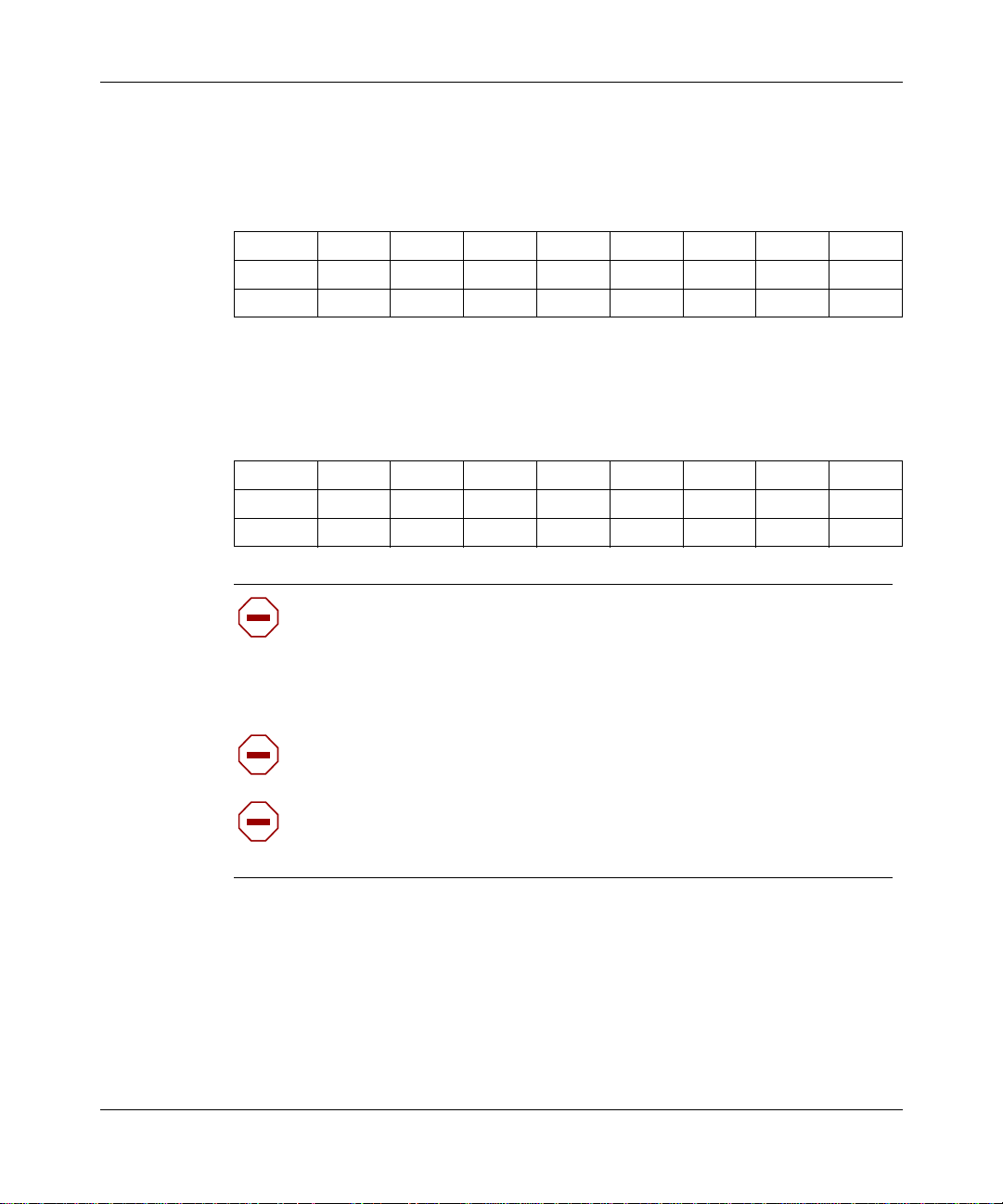
54 Chapter 4 Configuration switch settings
Table 9 shows the switch settings to disable the switch settings for resetting the
passwords and user-defined configurations
.
Table 9
Switch settings to disable switch settings for resetting the passwords
and user-defined configurations
12345678
OFF
ON
•• ••••
••
Table 10 shows the switch settings for resetting your unit to factory default
conditions.
Table 10
Switch settings for resetting factory default conditions
12345678
OFF
ON
Caution:
••• •••
If you use these switch settings to reset your unit to factory
••
default conditions, the following user-defined settings are removed or
reset: passwords, hosts, port mappings, unit configuration, access
restrictions, Web site list, cookie control settings, unit registration, and
encryption authorization.
313369-A
Caution:
If you purchased and installed the 3DES Encryption Module
(part number DM0010001), you need to reinstall it.
Caution:
If you used the switch settings in Table 9 to disable the switch
settings for resetting the passwords and user-defined configurations,
these settings are re-enabled.
Page 55

Chapter 4 Configuration switch settings 55
Resetting your Contivity 100 unit
Before you reset your Contivity 100 unit, be sure to back up the configuration so
that you can easily restore it. For details, refer to Using the Contivity Branch
Access Management Software Version 7.20.
To reset your Contivity 100 unit:
1
Turn of f your unit.
2
Record the current switch settings of your unit.
3
Set the switches to the configuration you want.
Refer to “Switch settings for special configurations” on page 53.
4
Turn on your unit.
The LEDs on the front of your unit flash and then glow steadily amber,
including the Power LED, when they completely match the sequence for the
selected switch settings.
Note:
effect and for the LEDs to glow amber.
Note:
the switch settings for resetting the passwords and user-defined
configurations, and you try to reset the passwords (Table 7) or reset the
passwords and user-defined configurations (Table 8), the Power LED
glows amber and LEDs 1–8 flash red in the sequence of the selected
switch settings.
5
Turn of f your unit.
6 Reset the switches using the information recorded in step 2.
Refer to Table 5 on page 52 or Table 6 on page 52.
7 Turn on your unit and then do one of the following:
• If you reset the passwords (Table 7) or disabled the switch settings for
resetting the passwor ds and user -defined conf igurations (Table 9 ), you are
finished with this procedure.
You may have to wait several minutes for the new settings to take
If you have already used the switch settings in Table 9 to disable
Setting Up the Contivity 100 Unit
Page 56

56 Chapter 4 Configuration switch settings
• If you reset the passwords and user-defined configurations (Table 8) or
reset the unit to f actor y defa ult s (Table 10), LED 2 glows amber when the
unit is ready for configuration. Continue with step 8.
Note:
8
Configure your unit.
You may have to wait several minutes for LED 2 to glow amber.
For details, refer to Installing the Contivity Branch Access Management
Software Version 7.20.
313369-A
Page 57

Chapter 5
LEDs: support and diagnostic functions
This chapter describes the LEDs on your Contivity 100 unit and how you can use
them to interpret activity on your unit.
Interpreting Contivity 100 unit LEDs
The front panel of the Con tivit y 100 uni t has t wo sets o f LEDs, the eig ht LEDs on
the left indicate failures and operational status of the unit. The Power LED is
always lit when your unit is turned on. The 14 LEDs (at the bottom, center of the
unit) display status and settings for the seven-port Ethernet switch.
Figure 8 illustrates the LE Ds on the fro nt of the Contivity 100 unit.
57
Setting Up the Contivity 100 Unit
Page 58

Power
10/100 Link/Activity
HDX/FDX
12345678
S1 S2 S3 S4 S5 S6 S7
58 Chapter 5 LEDs: support and diagnostic functions
Figure 8
12345678
Contivity 100 unit LEDs
Contivity
Power
10/100 Link/Activity
HDX/FDX
S1 S2 S3 S4 S5 S6 S7
100
9868EC
LEDs 1 through 8 and Power LED at power-up sequence
If a failure occurs during the power-up sequence, the Power LED glows amber,
and one or more of LEDs 1 through 8 glow red. This sequence indicates a
hardware problem. Call the Nortel Networks Technical Solutions Center
(page 23) for assistance.
If all LEDs glow amber, or none of the LEDs illuminates, check that the power
voltage selector switch setting matches your power voltage. For more
information, see “Setting the power voltage selector switch” on page 34.
313369-A
Caution: During nor mal ope ration, the Powe r LED glows green, exc ept
when updating the internal flash memory. While updating the flash
memory, the Power LED glows amber. This amber LED indicates that it
is not safe to turn off the unit without potentially damaging the contents
of flash memory.
Page 59

Chapter 5 LEDs: support and diagnostic functions 59
LEDs 1 through 8 and the Power LED during operation
After the power-up sequence is complete, the LEDs indicate status and activity
during operation as shown in Table 11.
Table 11
LED # Color Appearance Meaning
Power Green Solid Unit has electrical power and is turned on.
Power Green and
1-8 Amber Solid Power voltage selector switch is set to 230 but
1 Green Blinking Unit is operating norma lly.
2 Green Solid Unit is ready to service clients.
2 Green and
2 Amber Solid Unit is ready to be configured, but cannot
3-8 Green Solid Indicated interface (see Note below) is online.
3-8 Green Flashing Indicated interface (see Note below) is dialing or
3-8 Green and
3-8 Red Solid Indicated interface (see Note below) has failed.
LED status and appearance during operation
Amber
Amber
Amber
Solid Green and
Flashing Amber
Solid Green and
Flashing Amber
Solid Green and
Flashing Amber
Unit is updating flash memory. DO NOT TURN
THE UNIT OFF until the Power LED re turns to
green.
the power cord is plugged into a 110 voltage
plug.
Unit is communicating wit h clients.
service clients (normally occurs before unit has
been configured).
attempting connecti on.
Traffic is on the in dicated interface.
Note:
The “indicated interface” is the interface associated with the
LED’ s number . This infor mation is available in the main dialog box of the
Setup program. For more information, refer to Using the Contivity Branch
Access Management Software Version 7.20.
Setting Up the Contivity 100 Unit
Page 60

60 Chapter 5 LEDs: support and diagnostic functions
Using the seven-port autosensing Ethernet switch LEDs for troubleshooting
The seven-port autosensing Ethernet switch has two LEDs for each port on the
Ethernet switch. The top row of th ese LEDs displa ys speed, link , and activity. The
bottom row of LEDs displays whether the unit is operating in full- or half-duplex
mode.
Use the LED display to help you identify the type of problem with the Ethernet
switch and then verify tha t:
• The Ethernet switch is powered on.
• Each cable and port connection has the correct pin assignment and that no
connectors are loose.
• The Link/Activity LED glows for each port used.
If the Link LED is not on, do the following:
• Verify that the device connected to the Ethernet switch has a properly
functioning power supply.
• Try using a different port on the Ethernet switch to connect the device.
• Try using a different port on the device connected to the Ethernet switch.
Table 12 describes the LEDs that monitor the seven-port Ethernet switch.
Table 12
Label Color Activity Meaning
10/100 Link/Activity Green Solid Port is connected at 100 Mb/s.
10/100 Link/Activity Amber Solid Port is connected at 10 Mb/s.
10/100 Link/Activity Green Blinking 100 Mb/s activity is occurring on the port.
10/100 Link/Activity Amber Blinking 10 Mb/s activity is occurring on the port.
FDX Green Solid Port is operating in full-duplex mode.
FDX Off Off Port is operating in half-duplex mode.
Ethernet switch port status LEDs
313369-A
Page 61

Chapter 6
Out-of-band management support
This chapter describes how to set up your Contivity 100 unit for out-of-band
management. This feature enables you to configure your unit without installing
the unit on a network or loading the Contivity Branch Access management
software.
After you connect a dumb terminal or a smart terminal (for example, a PC, a
Macintosh*, or a UNIX* workstation) and terminal emulation software (for
example, AniTa Termin al Emul ator* , HyperTerminal*, or ProComm Plus *) t o the
unit’s AUX port, you can use CLI commands to configure the unit. For details,
refer to Reference for the Contivity Branch Access Command Line Interface
Version 7.20.
You can use out-of-band management any time, including for initial
configuration, troubleshooting, or daily management of the unit. This chapter
describes how to use a 32-bi t Windows* operating system and the HyperTerminal
terminal emulation software to:
61
• Connect directly to your unit with a dumb or smart terminal for out-of-band
management. For details, refer to “Configuring the Contivity 100 unit through
a direct connecti on, ” next . You must suppl y a n ull modem c able (also ref erred
to as a PC-to-PC file transfer cable) to connect a terminal to your unit.
• Configure an external modem to be used with a dial-up dumb or smart
terminal for out-of-band management. For details, refer to “Configuring the
Contivity 100 unit through a dial-up connection” on page 66. You must
supply a DB-9 serial cable to connect a dial-up modem to your unit.
These procedures assume that you have installed and turned on the unit and it is
operating properly ( no LEDs a re gl owing red). For mor e inf ormation on ins talling
the Contivity 100 unit hardware refer to Chapter 2, “Contivity 100 unit hardware
installation,” on pa ge 27. For more in formation on the re quired con nection ca bles,
refer to Appendix B, “Adapter cable pinout diagrams,” on page 73.
Setting Up the Contivity 100 Unit
Page 62

62 Chapter 6 Out-of-band managemen t suppo rt
Configuring the Contivity 100 unit through a direct connection
To configure the Contivity 100 unit through a direct connection to a dumb or
smart terminal using the out-of-band management feature, you must:
1
Use the Configurati on switc hes on t he back o f the Co ntivity 100 un it to set the
unit’s AUX port connection speed (115200 baud or 9600 baud) to match the
terminal’s connection speed.
Note:
both 115200 baud (default) and 9600 baud. Some dumb terminal devices
or terminal emulation software (for example, AniTa Terminal Emulator),
do not support the 115200 baud rate. In this case, you must set the unit’s
AUX port connection speed to 9600 baud. For details, refer to “Switch
settings for the AUX port speed” on page 52.
2
Connect the unit to the te rminal.
3
Use terminal emulation software to configure and establish a connection.
The Contivity 100 unit’s AUX port supports connection speeds of
Connecting the Contivity 100 unit directly to a terminal
This procedure provides instructions for connecting the Contivity 100 unit to a
dumb terminal or smart terminal (for example, a PC, a Macintosh, or a UNIX
workstation).
Note:
ready for configurat ion. You may have to wait several minutes f or LED 2
to glow amber. If the unit is configured and operating properly, LED 2
glows green.
If the unit is unconfigured, LED 2 glows amber when the unit is
313369-A
Page 63

Chapter 6 Out-of-band management support 63
To connect the Contivity 100 unit to a terminal:
1
Plug one end of the null modem cable into the AUX port on the rear of the
unit.
2
Plug the other end of the cab le into the serial port on the t erminal.
You can now use the terminal to configure your unit using the command line
interface. For details, refer to Reference for the Contivity Branch Access
Command Line Interface Version 7.20.
Configuring terminal emulation software for a direct connection
Regardless of the terminal emulation environment you use, you must:
• Set the flow control to hardware (RTS/CTS) in the terminal em ulation
software.
• Connect the unit’s AUX port to an available COM port on the terminal.
This procedure provides instructions for configuring the HyperTerminal terminal
emulation software on a PC using a connection speed of 115200 baud and the
COM1 port.
Caution:
before you proceed. You may have to wait several minutes for LED 2 to
glow amber.
To create a HyperTerminal PC connection profile:
1 Start the HyperTerminal software.
The Connection Description dialog box opens (Figure 9).
If you are configuring the unit, wait for LED 2 to glow amber
Setting Up the Contivity 100 Unit
Page 64
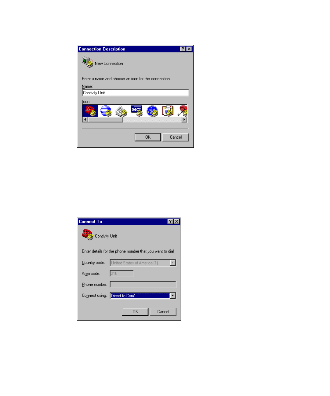
64 Chapter 6 Out-of-band managemen t suppo rt
Figure 9
2
3
4
HyperTerminal Connection Description dialog box
In the Name box, enter a name for the connection.
In the Icon area, select an icon for the connection.
Click OK.
The Connect To dialog box opens (Figure 10).
Figure 10
HyperTerminal Connect To dialog box
313369-A
5 From the Connect using list, select t he PC’s COM port that is connected to the
unit (in this example, COM1), and then click OK.
The COM1 Properties dialog box opens (Figure 11).
Page 65
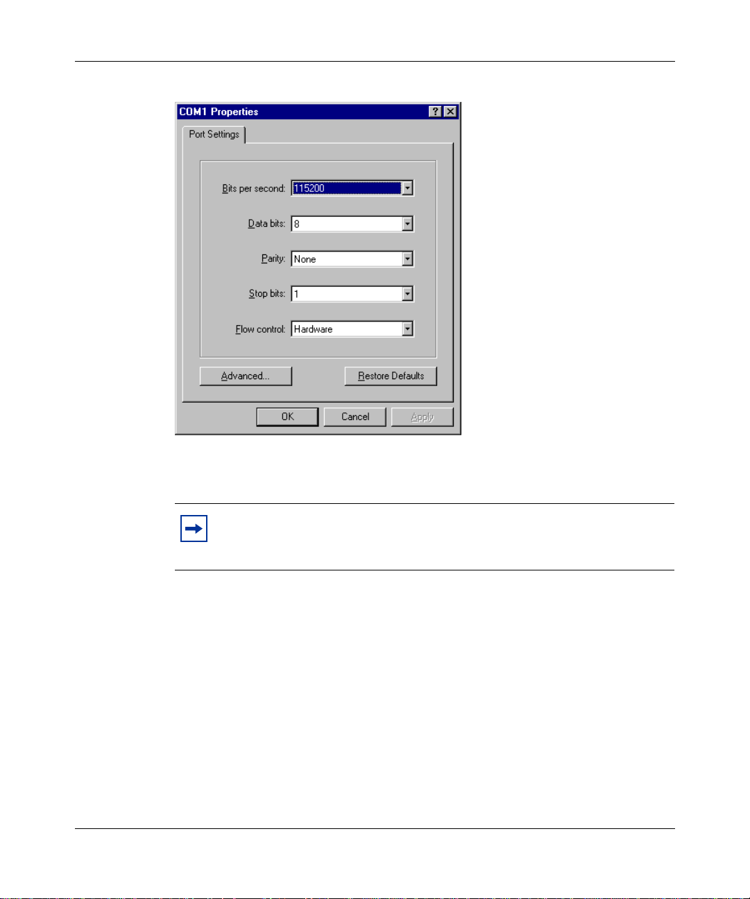
Chapter 6 Out-of-band management support 65
Figure 11
6
From the Bits per second list, select 115200 to set the connection speed, and
HyperTerminal COM1 Properties dialog box
then click OK.
Note:
The connection speed should match the unit’s AUX port
connection speed. If you are using terminal emulation software that does
not support 115200 baud, select 9600 baud.
HyperTerminal establishes a connection to the unit. If your unit is password
protected, the session begins by requesting a password. Enter the password
for the unit and then press [Enter].
If you enter an incorrect password, the message “Incorrect Login” is
displayed and you are prompted to enter a correct password. You are given
two more chances before the Contivity 100 unit ends the session and
disconnects you.
When you successfully log on, the command prompt is displayed (Figure 12) and
you can begin using CLI commands to configure the unit. For details, refer to
Reference for the Contivity Branch Access Command Line Interface Version 7.20.
Setting Up the Contivity 100 Unit
Page 66

66 Chapter 6 Out-of-band managemen t suppo rt
Figure 12
Instant Internet(tm) version 7.20
Copyright (c) 1995-2001 Nortel Networks Corporation
ii#
Command prompt
Configuring the Contivity 100 unit through a dial-up connection
To configure the Contivity 100 unit through a dial-up connection using the
out-of-band management feature, you must:
1
Use the Configurati on switc hes on t he back o f the Co ntivity 100 un it to set the
unit’s AUX port connection speed to 9600 baud. For details, refer to “Switch
settings for the AUX port speed” on page 52.
2
Connect the modem to a terminal.
3
Use terminal emulation software to configure the modem connection settings.
Note:
support 115200 baud, you do not have to change the unit’s AUX port
speed to 9600 baud (step 1). You can connect at 115200 baud.
If you know that your modem and terminal emulation software
313369-A
4
Connect the modem to your unit.
Connecting a modem to a PC
For this procedure, you do not need to load the modem drivers on the PC.
Note: You can also connect a dumb terminal to a modem in a similar
manner.
To connect a modem to a PC:
1 Connect the modem’s power cord to the modem and the power outlet, as
described in the modem’s installation instructions.
2 Plug one end of the DB9 serial cable into the modem.
Page 67
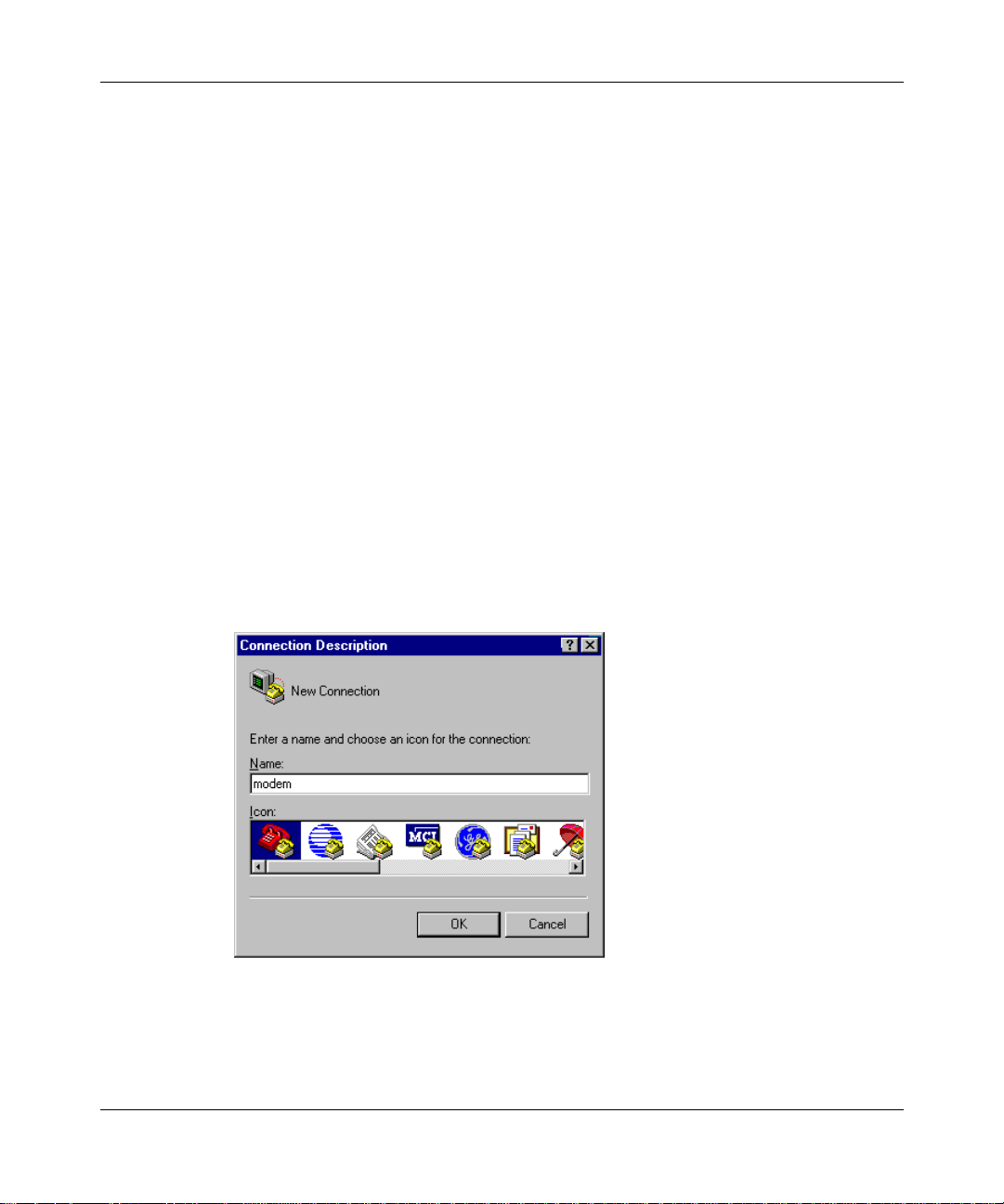
Chapter 6 Out-of-band management support 67
3
Plug the other end of the cable into the serial (COM) port on the PC.
4
Turn on the modem.
Configuring modem connection settings
To configure modem connection settings, you must set the modem to answer on
the first ring (auto-answer) with the command string:
enable you to configure the modem to auto-answer using DIP switch settings.
Refer to your modem’s documentation for instructions.
This procedure provides instructions for configuring modem connection settings
using the HyperTerminal terminal emulation software on a PC using a modem
speed of 9600 baud and the COM1 port.
To configure modem connection settings using HyperTerminal:
1
Start the HyperTerminal software.
ats0=1&w. Some modems
The Connection Description dialog box opens (Figure 13).
Figure 13
HyperTerminal Connection Description d ialog box
2 In the Name box, enter a name for the connection.
3 In the Icon area, select an icon for the connection.
4 Click OK.
Setting Up the Contivity 100 Unit
Page 68
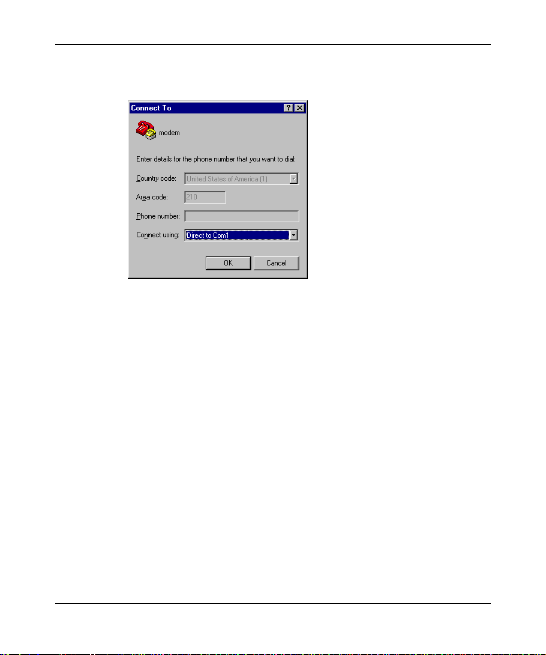
68 Chapter 6 Out-of-band managemen t suppo rt
The Connect To dialog box opens (Figure 14).
Figure 14
5
From the Connect using li st, selec t the P C’s COM port that is connected to the
HyperTerminal Connect To dialog box
modem (in this example, COM1), and then click OK.
The COM1 Properties dialog box opens (Figure 15).
313369-A
Page 69
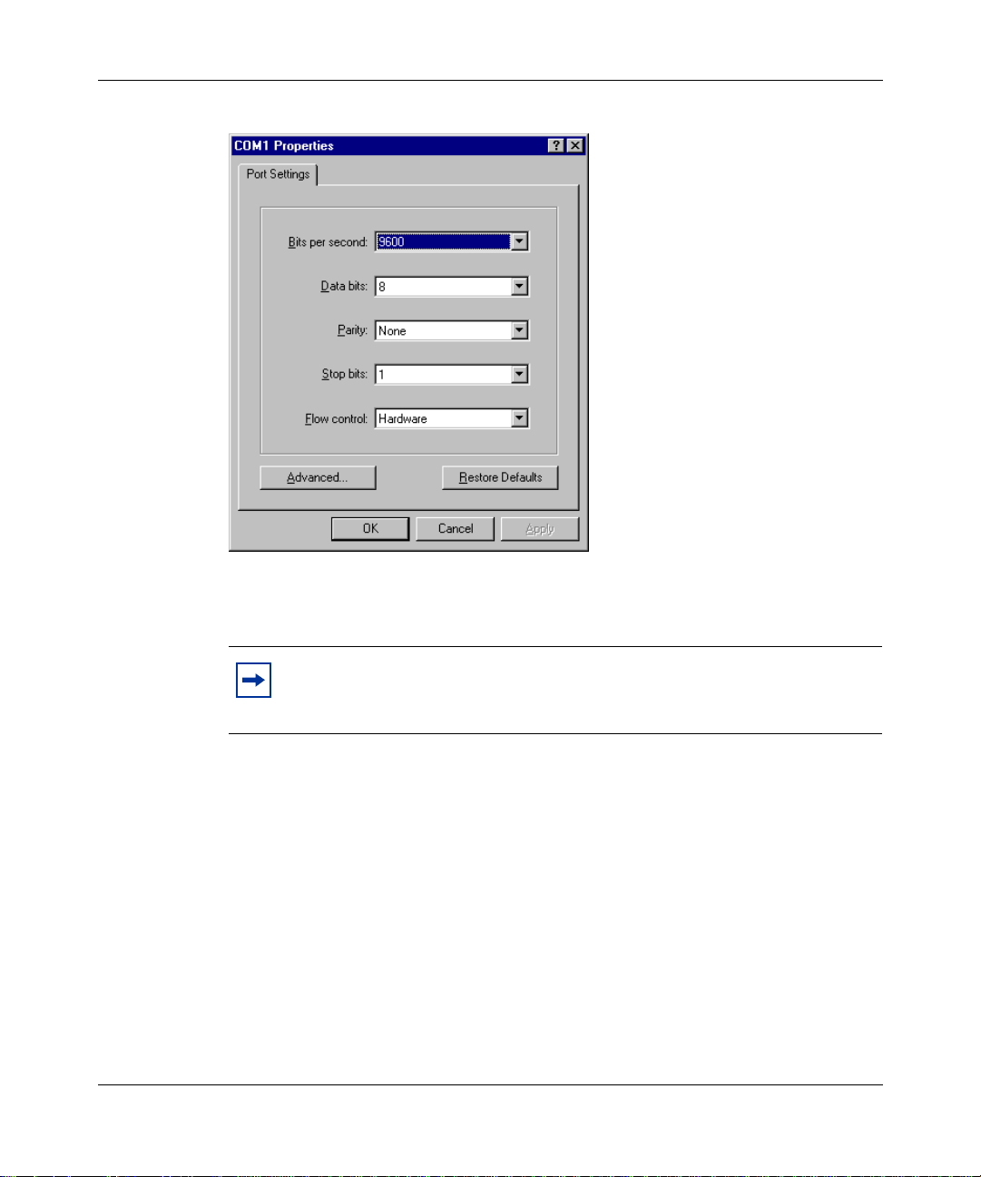
Chapter 6 Out-of-band management support 69
Figure 15
6
From the Bits per second list, select 9600 to set the modem speed, and then
HyperTerminal COM1 Properties dialog bo x
click OK.
Note:
The connection speed must match t he uni t’s AUX port connection
speed. If you are using a modem and terminal emulation software that
supports 115200 baud, select 115200 baud.
HyperTerminal establishes a connection to the modem and the cursor is
positioned in the main HyperTerminal dialog box.
7
Enter:
ats0=1&w
This command instructs the modem to answer on the first ring and saves the
settings to the modem. Some modems respond with “OK” or a similar
message when the settings are saved to the modem.
8 Disconnect the modem from the PC.
Setting Up the Contivity 100 Unit
Page 70

70 Chapter 6 Out-of-band managemen t suppo rt
Connecting a modem to the Contivity 100 unit
Before you connect the modem to the Contivity 100 unit, you must turn off the
unit.
Note:
properly configured the modem connection settings. For details, refer
“Configuring modem connection settings” on page 67.
To connect a dial-up modem to the Contivity 100 unit:
1
Turn of f the unit.
2
Plug one end of the DB9 serial cable into the AUX port on the rea r of the unit .
3
Plug the other end of the cab le into the modem.
4
Plug one end of the telephone cord into the modem and the other end into the
wall phone jack.
5
Turn on the modem.
6
Turn on the unit.
Note:
may have to wait several minutes for LED 2 to glow amber.
Before you continue with this procedure, be sure that you have
If you are configuring the unit, wai t for LED 2 t o glow amb er. Y ou
Connecting to a Contivity 100 unit
To connect to the Contivity 100 unit:
Dial the telephone number of the modem attached to the unit.
After you establish a conne ction, you can begi n using CLI commands to conf igure
the unit. For details, refer to Reference for the Conti vity Br anch Access Command
Line Interface Version 7.20.
313369-A
Page 71

Appendix A
Technical specifications
This appendix describes the physical and environmental specifications for your
Contivity 100 unit.
Physical specifications
The Contivity 100 uni t is 12 i nches wid e by 14. 39 inches deep by 2.6 4 inches high
and weighs 8.8 pounds.
Electrical specifications
• Input voltage: 100-127Vac or 200-240Vac
• Input current: 4A or 2A
• Frequency: 50/60 Hz
• Power consumption: 85 watts maximum
• Safety agency approvals: UL cUL Listed, TUV Rheinland Japan, TUV
Rheinland Argentina S.A., NOM
71
Setting Up the Contivity 100 Unit
Page 72

72 Appendix A Technical specifications
Environmental specifications
The operating and nonoperating environment for the Contivity 100 unit is as
follows:
• Operating temperature: 0° to 40° C maximum
• Nonoperating temperature: -25° to 70° C maximum
• Operating humidity:
— 8% minimum to 80% maximum
— Relative humidity: noncondensing
• Nonoperating humidity
— 5% minimum to 80% maximum
— Relative humidity: noncondensing
• Operating altitude: 8,000 feet (2,438 meters) maximum
• Nonoperating altitude: 30,000 feet (9,144 meters) maximum
• Acoustic noise: 53dBA at 3 feet
313369-A
Page 73

Appendix B
Adapter cable pinout diagrams
This appendix describes the pinout settings for the modem (DB-9 serial) and null
modem adapter cables.
Remote access adapter cables
If you want to connect a PC or dial-up modem directly to your Contivi ty 100 unit
to configure the unit using CLI commands (out-of-band management), you must
provide the connection cable. These are standard cables. You can have a cable
made according to the pinout diagrams in this appendix or you can purchase the
cable from a computer supply store.
For information on configuring your unit remotely, refer to Reference for the
Contivity Branch Access Command Line Interface Version 7.20.
73
Null modem adapter (PC-to-PC) cable
Figure 16 shows the pinout se ttings for a null modem adapter cable (also referred
to as a PC-to-PC file trans fer c able) . This s erial ca ble must have t wo DB- 9 female
connectors.
Use a null modem cable to connect a PC to the unit’s AUXport for out-of-band
management.
Setting Up the Contivity 100 Unit
Page 74

74 Appendix B Adapter cable pinout diagrams
Figure 16
DB-9 Connector
(Female)
TX
RX
RTS
CTS
DSR
DCD
DTR
GND
Null modem adapter cable pinout diagram
3
2
7
8
6
1
4
5
Modem adapter cable
Figure 17 shows the pinout settings for a modem adapter cable. This serial cable
must have a DB-9 female connector and a DB-25 male connector.
Use a modem cable to connect a dial-up modem to the unit’s AUX port for
out-of-band management.
DB-9 Connector
(Female)
RX
2
TX
3
CTS
8
RTS
7
DTR
4
DCD
1
DSR
6
GND
5
9959EA
313369-A
Figure 17
DB-9 Connector
(Female)
RX
TX
RI
1
2
3
4
5
6
7
8
9
DCD
DTR
GND
DCD
DSR
CTS
Modem adapter cable pinout diagram
DB-25 Connector
(Male)
8
3
2
20
7
6
4
5
22
9958EA
Page 75

Index
75
Numbers
3DES Encryption Module 54
A
acronyms 20
analog modem 26
AniTa Terminal Emulator 61
AUX port
connection speed 52
modem adapter cable 74
null modem cabl e 73
out-of-band management 61
C
cable
100BASE-T Ethernet connection 26
10BASE-T Ethernet connection 26
crossover 49
DB-9 serial 61
dial-up connection 25
gray 26
ISDN connection 25
MDI 49
MDI-X 49
modem 74
null modem 61, 73
PC-to-PC file transfer 61, 73
pinout diagrams 73
red 26
remote access 73
RJ-11 connecti o n 25
RJ-45 connection 26
straight-through 49
uplink 49
configuration
out-of-band management 61
terminal emulation software 61
Configuration switch settings
AUX port connection speed 52
disabling 54
normal operation 52
position 51
resetting passwords 53
resetting to factory default conditions 54
resetting user-defined configurations 53
special configurations 53
connection
dial-up 26
DMZ 30
ISDN 26
PPPoE 26
customer support 23
D
DB-9 serial cable 61
Demilitarized Zone (DMZ) 28
DIP switch. See Configuration switch
DMZ connection 30, 37
dumb terminal 61
E
Eth1
Ethernet switch 30, 37
LAN connection 30, 37
Setting Up the Contivity 100 Unit
Page 76

76 Index
Eth2
built in 28
DMZ connection 30, 37
Eth3 29
external modem connection 37
WAN connection 30
Ethernet connection
100BASE-T 26
10BASE-T 26
Ethernet switch
features 48
function 47
LAN connection 37
LEDs 60
troubleshooting 60
F
factory default conditions, resetting 54
flash memory 58
full-duplex (FDX) LED 48, 60
H
L
LEDs
about 57
activity 59
after power-up sequence 59
Ethernet switch 60
full-duplex (FDX) 48, 60
half-duplex (HDX) 48, 60
interpreting 57
Link/Activity 48, 60
normal operation 59
power-up sequence 58
red 55, 58
status 59
troubleshooting 60
M
MDI 49
MDI-X 49
modem cable 74
modem, analog 26
Multilink Protocol (MP) 26
half-duplex (HDX) LED 48, 60
HyperTerminal
connection profile, modem 67
connection profile, PC 63
out-of-band management 61
I
ISDN connection
configuration option 26
Multilink Protocol 26
NT1 26
synchronous PPP 26
313369-A
N
NT1 31
null modem cable 61, 73
O
out-of-band management
cables 73
dial-up connection 66
direct connection 62
Page 77

Index 77
P
package contents 25
password
incorrect 65
providing 65
resetting 53
PC-to-PC file transfer cable 61, 73
phone cord 25
Point-to-Point Protocol (PPP) 26
Point-to-Point Protocol over Et hernet (PPPoE) 26
power cord warnings (multilingual) 33
Power LED 58
power switch 28
power voltage selector switch, setting 34
ProComm Plus 61
product support 23
publications
hard copy 22
related 21
R
RJ-11 connecto r 30
RJ-45 connector 31
T
technical publications 22
technical specifications 71
technical support 23
terminal emulation software 61
AniTa Terminal Emulator 61
COM1 port 63
connection speed 62, 66
HyperTerminal 61
modem command string 67
ProComm Plus 61
U
unit, resetting 55
user-defined configurations, resetting 53
V
voltage 34
W
wall mounting 38
S
smart terminal 61
support, Nortel Networks 23
Setting Up the Contivity 100 Unit
Page 78

78 Index
313369-A
 Loading...