

Nortel Meridian Companion, COMPANION 200 Maintenance Manual

n
COMPANION
COMPANION 200
Installation and Maintenance
For position only
Key line does not print
••••••
••••••
••••••
••••••


iv
P0725810 Issue 3.0 COMPANION 200 Installation and Maintenance Guide
Contents
Introducing the COMPANION 200 1
COMPANION 200 components 2
Controller 2
Base Stations 2
Administration Terminal 2
Portables 2
Installing the COMPANION 200 3
Summary 3
Preparing for the installation 3
Installing the equipment 4
Programming the COMPANION 200 4
Verifying the installation 4
Maintaining the COMPANION 200 5
Summary 5
Performing a Maintenance session 5
Troubleshooting the equipment 5
Replacing faulty equipment 5
Preparing for the installation 7
COMPANION 200 equipment 7
Required equipment 8
Optional equipment 9
COMPANION 200 configurations 9
You tr y i t 12
Power bar requirements 12
Base Station Powering 13
Installing the system in two rows 14
Installing the system in three rows 17
Other things to consider when you are planning the installation 19
Installation warnings and safety instructions 19
Installation warnings 19
Important safety instructions 20

v Contents
COMPANION 200 Installation and Maintenance Guide P0725810 Issue 3.0
Installing the hardware 23
Installing the Controller 23
Summary 24
Mounting the Controller 24
Installing the Software Cartridge 26
Installing a Line Cartridge 27
Installing an Expansion Cartridge 28
Installing Line Modules 30
Mounting a Line Module 31
Installing a Line Cartridge in a Line Module 34
Routing cables in the cable trough 35
Installing Base Station Modules 35
Mounting a Base Station Module 36
Routing cables in the cable trough 39
Installing power bars 39
Installing Remote Power Interconnect units 41
Summary 43
Mounting the Remote Power Interconnect unit 43
Upgrading an RPI-8 to an RPI-16 45
Wiring the RPI 46
Wiring the system 49
Understanding the wiring charts 49
Wiring the access lines 50
Wiring the TCM lines 54
Connecting the fiber cables 59
Installing cable trough end plates 62
Installing the Administration Terminal 63
Setting up the Administration Terminal 63
Mounting the Administration Terminal on the wall 64
Installing Base Stations 65
Positioning a Base Station 65
Mounting a Base Station 65
Installing external antennas 68
Installing an indoor directional external antenna 69
Installing an indoor omni-directional external antenna 70
Installing an outdoor omni-directional external antenna 71
Installing a lightning surge protector 73
Powering up 75
Programming the COMPANION 200 77
Introduction to programming 77
The Programming Record 77

Contents vi
P0725810 Issue 3.0 COMPANION 200 Installation and Maintenance Guide
Programming the COMPANION 200 77
The COMPANION 200 Administration Terminal 78
Configuration programming 80
Administration programming 81
Changing the Installer password 81
Changing the Registration password 82
Programming the system settings 83
System time 84
System date 85
Dial mode 85
Link time 87
Host delay 87
Gain pad 88
Optional system settings 88
Data Re-evaluation 90
Running Data Re-evaluation 91
Memory reset 95
Registering the portables 96
Verifying the installation 99
Verification checklist 99
Verifying a radio’s cell assignment 100
Verifying a radio’s antenna setting 101
Maintenance 103
Entering a Maintenance session 103
Ending a Maintenance session 104
Version number 104
Port status 104
Identifying a device by its port number 105
Verifying the version number of a device 106
Checking the state of a port 107
Disabling a device 108
Enabling a device 109
Module status 109
Checking the state of a module 109
Disabling a module 111
Enabling a module 112
Checking the Event/Alarm log 112
Checking the Administration log 114
Understanding alarm messages 116
Understanding event messages 119

vii Contents
COMPANION 200 Installation and Maintenance Guide P0725810 Issue 3.0
Troubleshooting 123
General troubleshooting procedures 123
Troubleshooting power problems 124
Troubleshooting the Controller 124
Troubleshooting the Administration Terminal 125
Troubleshooting a Line Module 125
Troubleshooting a Base Station Module 126
Troubleshooting a portable 127
Troubleshooting a Base Station 127
Troubleshooting an RPI 128
Replacing equipment 131
Controller 131
Controller Power Supply Unit 132
Software Cartridge 133
Line Cartridge 133
Expansion Cartridge 134
Line Module 134
Base Station Module 135
Power bar 136
RPI 136
Administration Terminal 137
Base Station 138
Appendix A: Regulatory information 139
Registration 139
Safety 139
Equipment attachment limitations 139
Telecom Compliance 140
Telephone Company Notification 140
Rights of the Telephone Company 140
Radio Frequency Interference 141
Load Number 141
Repair facility 141
General installation warnings 142
Appendix B: Technical specifications 143
COMPANION 200 143
Environment 143
Radiated and conducted emissions 143
Radiated electromagnetic immunity 143
Conducted interference immunity 143
Mechanical requirements 144

Contents viii
P0725810 Issue 3.0 COMPANION 200 Installation and Maintenance Guide
Transportation methods 144
Controller 144
Power Supply Unit 145
Power bar 145
Software Cartridge 146
2-port expansion cartridge 146
6-port expansion cartridge 146
Line Cartridge 146
Line Module 147
Base Station Module 147
Fiber Cable Spool 148
RPI 148
COMPANION Base Station 148
Base Station 148
Base Station plug-top power supply 149
External antennas 150
Indoor omni-directional antenna 150
Indoor directional antenna 150
Lightning surge protector 150
Outdoor omni-directional antenna 151
COMPANION 200 Administration Terminal 151
Remote Access Device 152
Appendix C: Programming overview 153
Appendix D: Programming the host switch 155
Host switch programming 155
Directory number assignment 155
Independent assignment 156
Parallel assignment (separate directory numbers) 156
Twinned assignment 157
Caller ID display 160
Message waiting indication 160
Appendix E: Installing Base Station plug-top power supplies161
Positioning a Base Station 161
List of Terms 167
Index 177

ix Contents
COMPANION 200 Installation and Maintenance Guide P0725810 Issue 3.0
10
P0725810 Issue 3.0 COMPANION 200 Installation and Maintenance Guide
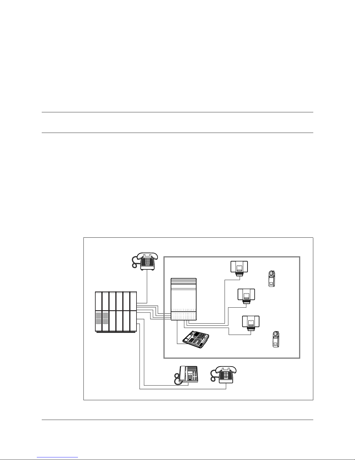
Introducing the COMPANION 200
The COMPA NION 200 adds wireless capability to an existing
telephone switching system, known as the host switch. The host
switch may be a Private Branch Exchange (PBX) or the Public
Switched T elephone Netw ork (PSTN). The COMPANION 200 uses
radio technology to transmit and receive signals between portable
telephones and Base Stations connected to the COMPANION 200
Controller. The Controller connects to the existing host system by
standard analog ports. T o the host switch the C ontroller is a group of
analog telephones.
Figure 1: The COMPANION 200 system
Pwr
COMPANION 200
Host switch
Controller
Administration Terminal
Base Stations
Portables
Pwr

11 Introducing the COMPANION 200
COMPANION 200 Installation and Maintenance Guide P0725810 Issue 3.0
COMPANION 200 components
The COMPA NION 200 has the following major components:
• COMPANION 200 Controller
• COMPANION Base Stations
• Administration Termin al
• Portable telephones (portables)
Controller
The COMPANION 200 C ontroller connects to the hos t swit ch with
standard analog telephone lines (access lines), and to the Base
Stations, the Administration Terminal, and any Remote Access
Device (RAD) with T ime Compression Multiplexing (TCM) ports.
Support for access lines is provided by adding up to two Line
Cartridges to the Controller. With Line Modules and Base Station
Modules connected to Expansion Cartridges, the Controller can
handle additional access lines and Base Stations.
Base Stations
The COMPANION Base Stations form a radio link to the portables.
Each Base Station has two independent radios, each with two
internal antennas and a connector for an external antenna. Base
Stations can be powered remotely by a Remote Power Interconnect
unit (RPI), or locally by a power supply that plugs into an ac outlet.
The Base Station is designed to be installed indoors only. External
antennas can extend cov erage to areas more diff icult to reach such as
stairwells or tunnels. Each Base Station can support up to two radio
links at a time.
Administration Terminal
A Northern Te lecom M7310 terminal serves as the Administration
Terminal for the COMPANION 200 system. It is used in
configuration, administration, and maintenance programming
sessions. It does not support either incoming or outgoing calls.
Portables
The COMPANION portables are battery-powered, pocket-sized
portable telephones. The COMPANION 200 can support a
maximum of 152 portables. Each portable requires one access line.

Introducing the COMPANION 200 12
P0725810 Issue 3.0 COMPANION 200 Installation and Maintenance Guide
Portables can be assigned to users as their only communication
terminal, or in addition to their desk (wired) telephone.
Installing the COMPANION 200
Summary
1. Prepare for the installation
2. Install the equipment
3. Program the COMPANION 200
4. Verify the installation
Preparing for the installation
The person responsible for preparing for installation of the
COMPANI ON 200 must:
• Order the required equipment (for example, the Controller, an
Administration Terminal, modules and cartridges, Base St ations,
RPIs, portables, portable chargers, cables).
• Ensure the appropriate host switch hardware (for example line
cards, distribution frames) has been installed.
• Ensure the needed access lines and host features are available.
• Ensure there is space on the distribution frames for the cross
connections.
• Ensure the required ac outlets are available for the Base Stations
that will be powered locally.
• Ensure the required wiring is av ailable from the Base Station sites
to the distribution frames.
• Ensure all the timing information about the host switch is
available.
• Determine from the customer the host switch features and Class
of Service (COS) that will be available on each portable as well
as the desired interworking with the desk telephone (see
Appendix D for more information on programming the host
system).
• Ensure the appropriate host switch features have been
programmed for each access line going to the COMPANION
200.

13 Introducing the COMPANION 200
COMPANION 200 Installation and Maintenance Guide P0725810 Issue 3.0
• Ensure the appropriate interworking with the wired telephones
has been enabled.
Installing the equipment
The person responsible for installing the COMPANION 200 must:
• Install the COMPANION 200 Controller and all the required
modules, ensuring all cartridges are properly inserted.
• Connect all the wiring from the Controller and the modules to the
distribution frames.
• Install the Administration Terminal.
• Install the Base Stations and external antennas (if any) at the sites
identified during the site planning, and connect the TCM and
power lines from the distribution block or frames to the Base
Stations.
• Power up the COMP ANION 200 and verify that the time and date
appear on the Administration Terminal.
• Complete the appropriate sections of the COMPANION 200
Programming Record.
Programming the COMPANION 200
The person responsible for programming the COMPANION 200
must:
• Program the access line characteristics (timing, dial mode, etc.)
to match the host switch requirements.
• Program any external antennas on Base Station radios.
• Complete the appropriate sections of the COMPANION 200
Programming Record.
• Confirm that all the access lines are available for use.
• Register the portables.
Verifying the installation
The person responsible for post-installation verifying must:
• Ensure that the COMP ANION 200 system is functional.
• Verify the radio coverage of the COMPANION 200.

Introducing the COMPANION 200 14
P0725810 Issue 3.0 COMPANION 200 Installation and Maintenance Guide
Maintaining the COMPANION 200
Summary
1. Perform a Maintenance session
2. Troubleshoot the equipment
3. Replace faulty equipment
Performing a Maintenance session
Performing a Maintenance session can help you detect hardware
failures and operational pr oblems. Using the Administration log and
the Event/Alarm log, you can determine what type of event triggered
an alarm and when the alarm occurred.
Troubleshooting the equipment
Troubleshooting the equipment invol ves determining if the problem
is with the COMPANION 200 hardware or its software.
Replacing faulty equipment
Follow the steps in the section “Replacing equipment” to remove
faulty equipment and to install its replacement.

15 Introducing the COMPANION 200
COMPANION 200 Installation and Maintenance Guide P0725810 Issue 3.0
16
P0725810 Issue 3.0 COMPANION 200 Installation and Maintenance Guide
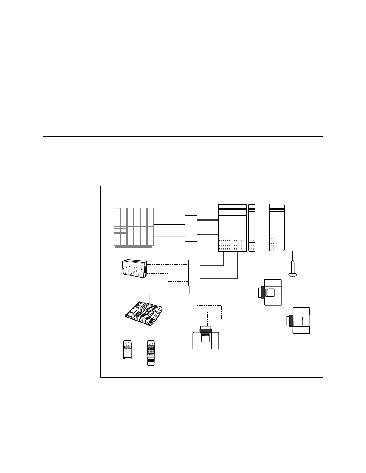
Preparing for the installation
COMPANION 200 equipment
Figure 2: Equipment overview
You can install two types of CO MPANION 200 equipment: requir ed
and optional. Required equipment is necessary for the operation of
the system. Optional equipment expands the capacity of the system
but is not necessary.
Administration
Terminal
TCM
lines
Host switch
. . .
Access
lines
RPI
distribution
frames
Controller, Line Module(s)
and Base Station Module(s)
25-pair
cables
25-pair
cables
Base Station
External
antenna
Base Station
Base Station
COMPANION
1
2
3
4
5
6
7
8
9
0
*
#
EMERGENCY
1 2 3
Release
4 5 6
Memory
7 8 9
Link
*
0 #
Shift
LineHomeOfficePublic
Redial
Delete
Emergency
ProgramOptionsPredial
Next Call
ABC DEF
GHI JKL MNO
PRS TUV WXY
COMPANION
Portables
Power
lines

17 Preparing for the installation
COMPANION 200 Installation and Maintenance Guide P0725810 Issue 3.0
The wiring to the COMPANION 200 Controller, Line Modules and
Base Station Modules is done using 25-pair cables with 50-pin
female connectors at one end. The other end of these cables
terminates on the distribut ion frames. All other wiri ng is done using
standard twisted-pair telephone cables.
Required equipment
The following is a list of the equipment you must install to have an
operational system:
• Controller: the heart of the COMPANION 200 system. It
provides support for Base Stations, access lines (portables), the
Administration Terminal, and any Remote Access Devices. You
need one Controller for each COMPANION 200 system.
• Software Cartridge: provides functionality to the
COMPANI ON 200 system. The Software Cartridge plugs into
the Controller.
• Line Cartridges: the interface between the host switch and the
COMPANION 200. Line Cartridges plug into the Controller and
the Line Modules. Each Line Cartridge supports up to four access
lines. There are two types of Line Cartridge available: the
Disconnect Supervision (DS) Analog Line Cartridge, which
provides standard features, and the CLASS Line Cartridge, which
provides Call Management Service (CMS) features.
• Base Stations: provide radio links to the portables.
• Remote Power Interconnect units: provide power to the Base
Stations.
• Portables: portable telephones. They can be assigned to users in
addition to, or instead of, a desk telephone (see Appendix D).
• Administration Terminal: you need one Administration
Terminal for each COMPANION 200 system.
!
Read the installation warnings and safety instructions at the end of
this section before installing the equipment.

Preparing for the installation 18
P0725810 Issue 3.0 COMPANION 200 Installation and Maintenance Guide
Optional equipment
The following is a list of the equi pment you can install to expand the
capacity of the COMPANION 200:
• Line Modules: expand user capacity. Each Line Module
connects to an Expansion Cartridge with a fiber optic cable. Each
Line Module holds up to three Line Cartridges.
• Base Station M odules: expand Base Station capacity . Each Base
Station Module connects to an Expansion Cartridge with a fiber
optic cable. Each Base Station Module supports 16 additional
Base Stations.
• Expansion Cartridges: provide the interface between the
Controller and the Line Modules and Base Station Modules. The
Expansion Cartridges plug into the Controller.
• Power bars: provide power to the Line Modules and Base
Station Modules.
• External antennas: provide radio links in areas where Base
Stations cannot be installed. Each external antenna (indoor or
outdoor) connects to a Base Station with a co-axial cable. When
installing an outdoor external antenna, you must route the coaxial cable through a lightning surge protector.
• Plug-top power supplies: provide power to Base Stations not
powered by an RPI.
• COMPANION Diagnostic Software (CDS): performs
diagnostics on the operating characteristics of the system. CDS
runs on a suitable personal computer (PC), and requires a RAD
(Remote Access Device) to communicate with COMPANION
200. See Appendix B for RAD specifications and part number.
COMPANION 200 configurations
You can configure the COMPANION 200 system to various
combinations of a ccess lines and Base S tations to pr ovide optim um
mobility service depending on:
• The site coverage requirements.
• The number of users (portables) to be supported.
• The anticipated traffic levels and patterns.
The following charts show all possible configurations (acces s lines
and TCM devices) for the COMP ANI ON 200.

19 Preparing for the installation
COMPANION 200 Installation and Maintenance Guide P0725810 Issue 3.0
To determine the number of Line Cartridges, Line Modules, and
Base Station Modules needed for a given configuration of access
lines and TCM lines as well as the type of Expansion Cartridge
required to support these modules:
1. Find the number of access lines in the top row. Each user and
each RAD modem needs one access line. This tells you how
many Line Modules (LM) you need.
2. To find out how many Line Cartridges you need, divide your
number of access lines by 4, and round up.
Note: The Controller can accommodate up to two Line
Cartridges, and each Line Module can accommodate up
to three Line Cartridges.
3. Find the number of TCM devices in the left column. Each Base
Station, Administration Terminal, and RAD needs one TCM
line. This tells you how many Base Station Modules (BM) you
need.
4. Read down the access lines column until you cross the TCM
devices row. The number in that box indicates the number of
external ports needed f or that conf iguration (a gr ay cell indi cates
an inv alid combination of access and TCM lines). This tells you
how many Expansion Cartridges you need. You can use any
combination of 2-port and 6-port Expansion Cartridges.
Note: Consider future expansion needs when choosing the
Expansion Cartridges.

Preparing for the installation 20
P0725810 Issue 3.0 COMPANION 200 Installation and Maintenance Guide
Modules and ports requirements
Table 1: Modules and ports requirements
BM = Base Station Module, LM = Line Module
access
→
TCM ↓
1-8
0 LM
9-20
1 LM
2132
2 LM
3344
3 LM
4556
4 LM
5768
5 LM
6980
6 LM
8192
7 LM
93104
8 LM
105116
9 LM
117128
10 LM
129140
11 LM
141152
12 LM
1-32
0 BM
0123456789101112
33-48
1 BM
123456789101112
49-64
2 BM
23456789101112
65-80
3 BM
3456789101112
81-96
4 BM
456789101112
97112
5 BM
56789101112
113128
6 BM
6 7 8 9 10 11 12
129144
7 BM
789101112
145160
8 BM
8 9 10 11 12
161176
9 BM
9 101112
177192
10 BM
10 11 12
193208
11 BM
11 12
209224
12 BM
12

21 Preparing for the installation
COMPANION 200 Installation and Maintenance Guide P0725810 Issue 3.0
Line Cartridge requirements
Number of Line Cartridges = number of access lines ÷ 4
You tr y it
Assume you are setting up a system for 53 users and 38 Base
Stations.
You need:
• one access line per user
• one TCM line per Base Station plus one TCM line for the
Administration Terminal
• Therefore, you must configure 53 access lines and 39 TCM lines.
Using the charts and the equation above, you see that you need:
• four Line Modules (since 53 is between 45 and 56)
• one Base Station Module (since 39 is between 33 and 48)
• fiv e expansionl ports (4 LMs and 1 BM), which can be one 6-port
Expansion Cartridge, one 2-port and one 6-port Expansion
Cartridges, or two 6-port Expansion Cartridges
• 14 Line Cartridges (53 ÷ 4 = 13.25, round up to 14).
Power bar requirements
After you have determined how many Line Modules and Base
Station Modules you need for the installation, use this table to see
how many power bars and additional power cords you need.
Modules Power bars
1–3 (+ Controller) 1
4–6 2
7–10 3
11–12 4
!
Do not daisy chain more than two power bars.
Daisy chaining more than two power bars compromises the electrical
safety of the product.

Preparing for the installation 22
P0725810 Issue 3.0 COMPANION 200 Installation and Maintenance Guide
Base Station Powering
The Remote Power Inter connect unit (RPI) allo ws Companion Base
Stations to be powered over the same type of cables that carry the
TCM signals. You can also power a Base Station locally with a plugtop power supply but a plug-top power supply requires an ac outlet
within 4 meters (wiring length) of the Base Station.
Each RPI output connector provides power for one Base Station
using one or two pairs of wires (power pairs).
Note: The RPI also provides pass-through connectivity for the
TCM signa l . Th e TCM wire s (TCM pair) f ro m t he
Controller connects to an RPI input connector, and is routed
to the appropriate output connector.
It is usually cheaper and more convenient to install RPIs than to
provide ac outlets and plug-top power supplies for each Base
Station. Using RPIs also makes it easier to add or move Base
Stations if the system configuration changes. Usually, you should
install RPIs in a location other than where the COMPANION
Controller and Modules are to prevent power management and
ventilation problems. The maximum input power requirement of
the RPI is 240 W ac, or 135 W if the unit is being powered by a
48 v dc source.
Note: To enhance the integrity of the system in cases wher e there
is more than one Base Station in a cell, you may connect the
Base Stations in that cell to different RPIs.
You should power Base Stations with RPIs in all but the following
circumstances:
• When Base Stations are in a separate building from the
Controller, and it is not cost effective to install RPIs with these
Base Stations.
• When the two-way cable dc loop resistance (including
interconnections) between a Base Station and its RPI exceeds 90
ohms (for example, more than 500 meters [one way] for one pair
of 0.6 mm wires)

23 Preparing for the installation
COMPANION 200 Installation and Maintenance Guide P0725810 Issue 3.0
Note: Remember that interconnections increase the loop resistance.
In some instances, you may want to power Base Stations with plug-
top power supplies. See Appendix E for more details on installing e
system in two rowsBase Stations powered by plug-top power
supplies.
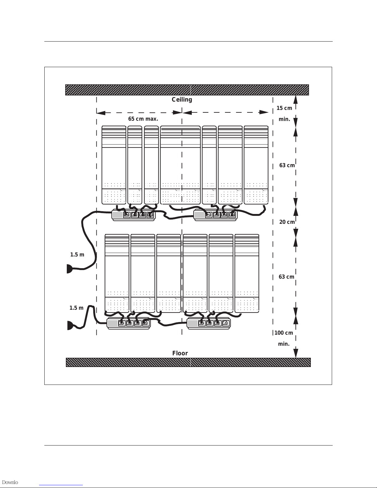
Installing the system in two rows
If vertical space is limited, install the system in two rows. See the
figure, “Recommended two-row installation” and keep the following
points in mind:
• T wo-row installation requires two po wer cords to the mains outlet
(maximum distance 1.5 m) and four power bars. (The power bars
are shown outside the troughs in the figure. This is for the sake of
clarity only).
• The longest fiber cable run from the Controller is to the bottom
left and right hand modules.
• Figure 3 shows a 12 Module System with nine Line Modules and
three Base Station Modules. However, the combination of Base
Station and Line Modules will vary according to your
requirements.
• The 130 cm horizontal distance (65 + 65 cm) shown in the figure
is the maximum possible distance. The actual distance depends
on the combination of Base Station and Line Modules installed.
• Center the Controller in the top row.
• Place the Base Station and Line Modules to the right and left of
the Controller.
• Mount the remaining Base Station and Line Modules in the row
above or below the Controller . Mount them to the left and right of
a vertical line centered on the Controller to a maximum of six
modules.
Table 2: Maximum power cabling distance (approximate)
Wire size Single-pair Double-pair
0.6 mm (22 AWG) 800 m 1200 m
0.5 mm (24 AWG) 500 m 1000 m
0.4 mm (26 AWG) 350 m 700 m

Preparing for the installation 24
P0725810 Issue 3.0 COMPANION 200 Installation and Maintenance Guide
• The recommended distance between the rows for thermal
dissipation and fiber cable connections is 15 to 20 cm.
• When you mount systems that are smaller than 12 modules, leave
room for future expansion and power requirements.
• This installation does not take into account space or power
requirements for the distribution blocks or RPIs.
• If you have six or less modules, install the system in a single row .
Install the controller and modules as shown in the top row of
figure 3 and observe the clearances shown. The clearance
between the bottom of the modules and the floor should be
100 cm minimum.
25 Preparing for the installation
COMPANION 200 Installation and Maintenance Guide P0725810 Issue 3.0
Figure 3: Recommended two-row installation
65 cm max.
Ceiling
Floor
65 cm max.
20 cm
15 cm
min.
63 cm
63 cm
100 cm
min.
1.5 m
1.5 m

Preparing for the installation 26
P0725810 Issue 3.0 COMPANION 200 Installation and Maintenance Guide
Installing the system in three rows
If horizontal space is limited, install the system in three ro ws. See the
figure, “Recommended thre e -row installation”and keep the
following points in mind:
• Three-row installation requires three power cords to the mains
outlet (maximum distance 1.5 m) and four power bars. (The
power bars are shown out side the troughs in the figure. This is for
the sake of clarity only).
• The longest fiber cable run from the Controller is to the top and
bottom left and right hand modules.
• The following figure shows a 12 Module System with nine Line
Modules and three Base Station Modules. Howe ver, the
combination of Base Station and Line Modules will vary
according to your requirements.
• The 110 cm horizontal distance (55 + 55 cm) shown in the figure
is the maximum possible distance. The actual distance depends
on the combination of Base Station and Line Modules installed.
• Center the Controller in the top row.
• Place the Base Station and Line Modules to the right and left of
the Controller to a maximum of four modules in the middle row.
• Mount the remaining Base Station and Line Modules in rows
above and below the Controller . Mount them to the left and right
of a vertical line centered on the Controller to a maximum of 4
modules per row.
• The recommended distance between the rows for thermal
dissipation and fiber cable connections is 15 to 20 cm.
• When you mount systems that are significantly smaller than 12
modules, leave room for future expansion and power
requirements.
• This installation does not take into account space or power
requirements for the distribution blocks or RPIs.
27 Preparing for the installation
COMPANION 200 Installation and Maintenance Guide P0725810 Issue 3.0
Figure 4: Recommended three-row installation
100 cm
min.
Floor
20 cm
15 cm
min
63 cm
63 cm
20 cm
63 cm
55 cm max55 cm max
Ceiling
1.5 m
1.5 m
1.5 m

Preparing for the installation 28
P0725810 Issue 3.0 COMPANION 200 Installation and Maintenance Guide
Other things to consider when you are planning the
installation
Ensure you have adequate wall space for the installation. If the
system you are installing is likely to grow, leav e enough room for it
to expand.
You do not have to install the RPIs in the same room as the
Controller.
You must install the Administration Terminal within 800 meters
(wiring length) of the Controller.
You must install Base Station within 1200 meters (wiring length) of
the Controller.
Keep in mind the power and cooling requirements for the system.
Do not connect in series (“daisy chain”) more than two power bars.
Install the Controller in the middle so that the fiber cables from all
the Line and Base Station Modules can reach the Controller.
Installation warnings and safety instructions
PLEASE READ THIS SECTION CAREFULLY to ensure your
safety and the safe operation of the equipment.
Installation warnings
!
To avoid electrical shock hazard to personnel or equipment
damage, observe the following precautions when installing
telephone equipment:
Never install telephone wiring during a lightning storm.
Never install telephone jacks in wet locations unless the jack is
specifically designed for wet locations.
Never touch non-insulated telephone wires or terminals unless the
telephone line has been disconnected at the network interface.
Use caution when installing or modifying the telephone lines.

29 Preparing for the installation
COMPANION 200 Installation and Maintenance Guide P0725810 Issue 3.0
Important safety instructions
When using your telephone equipment, basic safety precautions
should always be followed to reduce the risk of fire, electric shock,
and injury to persons, including the following:
• Follo w the warnings and instructions mark ed on the
COMPANI ON 200.
• Unplug the COMPANION 200 from the ac outlet before
cleaning. Use a damp cloth for cleaning. Do not use liquid
cleaners or aerosol cleaners.
• Do not use any part of the COMPANION 200 near water.
• Do not place the COMPANION 200, or any part of it, on an
unstable cart, stand or table. The COMPANION 200 may fall,
causing serious damage to it.
• Never place any part of the COMPANI ON 200 near or over a
radiator or heat vent.
• Never place any part of the COMPANION 200 in an enclosure
unless proper ventilation is pro vide d.
!
Do not connect the COMPANION 200 Administration Terminal or
Base Stations directly to a Central Office (CO) line interface.
Doing so may result in equipment damage.
!
COMPANION 200 Administration Terminals and Base Stations
must not be used as Off Premises Equipment, unless proper
protection is provided.
!
Check the lightning protectors at the cable entry point to the
building and pay special attention to the grounding.
Report any problems to the telephone company in writing. Because
COMPANION 200 Administration Terminals and Base Stations are
not lightning-protected, do not install them outside the building

Preparing for the installation 30
P0725810 Issue 3.0 COMPANION 200 Installation and Maintenance Guide
• Do not allow anything to rest on the power cord.
• Do not locate the COMPANION 200 where someone may walk
on the power cord.
• To avoid fire or electrical shock, do not overload ac outlets and
extension cords.
• T o a void touching dangerous voltage points or short out parts that
could result in fire or electrical shock, never push objects of any
kind into the COMPANION 200 slots.
• Never spill liquids of any kind on the COMPANION 200.
• To reduce the risk of electric shock, do not disassemble the
COMPANION 200. When any service or repair work is required,
send it to a qualified service person.
• Unplug the COMPANION 200 from the ac outlet and refer
servicing to qualified service personnel under the following
conditions:
– When a power cord is damaged or frayed.
– If the COMPANI ON 200 has been exposed to rain, or
liquid has been spilled on any part of it (if this happens,
disconnect it and then allow the COMP ANION 200 to dry
out to see if it still operates; do not open up the
COMPANI ON 200).
– If the housing of any part of the COMPANION 200 has
been damaged.
• Do not use any telephone to report a gas leak in the vicinity of the
suspected leak.
• CAUTION: T o elim inate the possibility of accidental damage to
cords, plugs, jacks, and other COMP ANION 200 components, do
not use sharp instruments during the assembly procedures.
• WARNING: To avoid damage to equipment, do not insert the
plug at the free end of an Administration Terminal cord directly
into a wall or baseboard jack.
• Slots and openings in the cabinet and the back or bottom are
provided for ventilation. To protect the COMPANION 200 from
overheating, do not block or cover these openings.
• This product is provided with a three-wire grounding type plug
with a third (grounding) pin. T his plug fits into a grounding type
ac outlet only . This is a safety feature. If you are unable to insert
the plug into the ac outlet, contact your electrician to replace your
obsolete ac outlet.

31 Preparing for the installation
COMPANION 200 Installation and Maintenance Guide P0725810 Issue 3.0
 Loading...