

Page 1

Nortel Communication Control Toolkit
Planning and Engineering Guide
Product release 5.0 Standard 5.01 June 2007
297-2183-924
Page 2

Page 3

Nortel Communication Control Toolkit
Planning and Engineering Guide
Publication number: 297-2183-924
Product release: 5.0
Document release: Standard 5.01
Date: June 2007
Copyright © 2007 Nortel Networks. All Rights Reserved.
Information is subject to change without notice. Nortel Networks reserves the right to make
changes in design or components as progress in engineering and manufacturing may warrant.
The process of transmitting data and call messaging between the Meridian 1 or DMS/MSL-100
switch and Communication Control Toolkit is proprietary to Nortel Networks. Any other use of the
data and the transmission process is a violation of the user license unless specifically authorized
in writing by Nortel Networks prior to such use. Violations of the license by alternative usage of
any portion of this process or the related hardware constitutes grounds for an immediate
termination of the license and Nortel Networks reserves the right to seek all allowable remedies
for such breach.
*Nortel, Nortel (Logo), the Globemark, and This is the Way, This is Nortel (Design mark),
CallPilot, Contivity, DMS, IVR, Meridian, Meridian 1, Meridian Mail, Meridian SL, Optivity,
Succession, and Symposium are trademarks of Nortel Networks.
CITRIX is a trademark of Citrix Systems, Inc.
INTEL, INTEL XEON, and PENTIUM are trademarks of Intel Corporation.
MICROSOFT, MICROSOFT ACCESS, WINDOWS, WINDOWS NT, and WINDOWS XP are
trademarks of Microsoft Corporation.
REPLICATION SERVER and SYBASE are trademarks of Sybase, Inc.
PCANYWHERE is a trademark of Symantec Corporation.
Page 4

Page 5

Planning and Engineering Guide v
Revision history
December 2006
The Standard 5.01 issue of the Nortel Communication
Control Toolkit Planning and Engineering Guide is
released. It contains updates for CRs and for Microsoft
Vista.
December 2006
The Standard 5.0 issue of the Nortel Communication
Control Toolkit Planning and Engineering Guide, Release
5.0, is released. It contains updates for telephone sets
based on CRs.
October 2006
The Standard 4.0 issue of the Nortel Communication
Control Toolkit Planning and Engineering Guide, Release
5.0, is released. It contains updates required to
terminology and server specifications for SU03.
June 2006
The Standard 3.0 issue of the Nortel Communication
Control Toolkit Planning and Engineering Guide, Release
5.0, is released.
May 2005
The Standard 2.0 issue of the Nortel Communication
Control Toolkit Planning and Engineering Guide, Release
5.0, is released.
March 2005
The Standard 1.0 issue of the Nortel Communication
Control Toolkit Planning and Engineering Guide, Release
5.0, is released.
Page 6

vi Communication Control Toolkit
Standard 5.01
Page 7

Planning and Engineering Guide vii
Contents
1 Getting started 9
About this guide . . . . . . . . . . . . . . . . . . . . . . . . . . . . . . . . . . . . . . . . . . . . . . . 10
Engineering Communication Control Toolkit . . . . . . . . . . . . . . . . . . . . . . . . 12
What’s new in Release 5.0? . . . . . . . . . . . . . . . . . . . . . . . . . . . . . . . . . . . . . . 13
Product description . . . . . . . . . . . . . . . . . . . . . . . . . . . . . . . . . . . . . . . . . . . . . 14
Related documents . . . . . . . . . . . . . . . . . . . . . . . . . . . . . . . . . . . . . . . . . . . . . 25
2 Communication Control Toolkit architecture 27
Architecture . . . . . . . . . . . . . . . . . . . . . . . . . . . . . . . . . . . . . . . . . . . . . . . . . . 28
Components . . . . . . . . . . . . . . . . . . . . . . . . . . . . . . . . . . . . . . . . . . . . . . . . . . 34
Communication Control Toolkit API application types . . . . . . . . . . . . . . . . . 39
3 Engineering Communication Control Toolkit 43
Section A: Engineering the server 45
Hardware requirements. . . . . . . . . . . . . . . . . . . . . . . . . . . . . . . . . . . . . . . . . . 46
Operating system configuration requirements . . . . . . . . . . . . . . . . . . . . . . . . 50
Capacity . . . . . . . . . . . . . . . . . . . . . . . . . . . . . . . . . . . . . . . . . . . . . . . . . . . . . 51
Guidelines to minimize capacity requirements. . . . . . . . . . . . . . . . . . . . . . . . 56
Section B: Engineering the client 59
Client requirements. . . . . . . . . . . . . . . . . . . . . . . . . . . . . . . . . . . . . . . . . . . . . 60
4 Engineering the switch 61
Section A: Engineering Meridian 1/Succession 1000 63
Meridian 1/Succession 1000 switch requirements . . . . . . . . . . . . . . . . . . . . . 64
Meridian 1/Succession 1000 switch capacity . . . . . . . . . . . . . . . . . . . . . . . . . 67
Supported phonesets . . . . . . . . . . . . . . . . . . . . . . . . . . . . . . . . . . . . . . . . . . . . 70
Section B: Configuring Meridian 1/Succession 1000 73
Overview. . . . . . . . . . . . . . . . . . . . . . . . . . . . . . . . . . . . . . . . . . . . . . . . . . . . . 74
Configuring the ELAN subnet (knowledge worker environment) . . . . . . . . . 75
Configuring CDNs . . . . . . . . . . . . . . . . . . . . . . . . . . . . . . . . . . . . . . . . . . . . . 81
Configuring TAPI phonesets . . . . . . . . . . . . . . . . . . . . . . . . . . . . . . . . . . . . . 83
Page 8

viii Communication Control Toolkit
Contents Standard 5.01
5 Engineering the network 85
Overview. . . . . . . . . . . . . . . . . . . . . . . . . . . . . . . . . . . . . . . . . . . . . . . . . . . . . 86
Contact center and self-service environments . . . . . . . . . . . . . . . . . . . . . . . . 87
Knowledge worker environment . . . . . . . . . . . . . . . . . . . . . . . . . . . . . . . . . . 91
Network traffic . . . . . . . . . . . . . . . . . . . . . . . . . . . . . . . . . . . . . . . . . . . . . . . 100
6 Setting up remote support with a VPN 105
Overview. . . . . . . . . . . . . . . . . . . . . . . . . . . . . . . . . . . . . . . . . . . . . . . . . . . . 106
Guidelines for the Remote Support VPN at the customer’s premises . . . . . 108
VPN configurations . . . . . . . . . . . . . . . . . . . . . . . . . . . . . . . . . . . . . . . . . . . 109
A Supported migration paths 113
Supported migration paths to Communication Control Toolkit 5.0 . . . . . . . 114
B Supported functions and events 117
Supported features . . . . . . . . . . . . . . . . . . . . . . . . . . . . . . . . . . . . . . . . . . . . 118
Supported events. . . . . . . . . . . . . . . . . . . . . . . . . . . . . . . . . . . . . . . . . . . . . . 122
C Standard call models 125
Inbound call models . . . . . . . . . . . . . . . . . . . . . . . . . . . . . . . . . . . . . . . . . . . 126
Index 151
Page 9

Planning and Engineering Guide 9
Chapter 1
Getting started
In this chapter
About this guide 10
Engineering Communication Control Toolkit 12
What’s new in Release 5.0? 13
Product description 14
Related documents 25
Page 10

10 Communication Control Toolkit
Getting started Standard 5.01
About this guide
Welcome
Communication Control Toolkit helps you implement Computer Telephony
Integration for installed and browser-based client integrations. It delivers a
single cross-portfolio multi-channel API that facilitates the integration of contact
center, knowledge worker, and self-service solutions with your client
applications. These client applications can be simple software phones, agent
telephony toolbars with screen pops, intelligent call management applications,
and so on.
Computer Telephony Integration
Computer Telephony Integration (CTI) describes an environment where
telephony systems and computer systems interact with each other. This
interaction can take many forms, including Interactive Voice Response (IVR),
computer controlled call routing, call recording, predictive dialing, client
desktop integration, and so on.
Most CTI applications support one or both of the following functions:
control of telephony communications, such as
Make call
Answer call
Route call
Transfer call
monitoring of telephony communications, such as
Pop an application screen when an inbound call arrives
Record call statistics
As the boundary between computer and telephony systems becomes more
blurred, the telephony platform is evolving to become a more integrated part of a
broader communications infrastructure that, among others, includes voice,
e-mail, instant messaging, and video.
Page 11

Planning and Engineering Guide 11
June 2007 Getting started
Who should read this guide
This guide is for Communication Control Toolkit system designers and technical
support staff members. It is also intended to be used by administrators who are
responsible for day-to-day management of Communication Control Toolkit.
Page 12

12 Communication Control Toolkit
Getting started Standard 5.01
Engineering Communication Control Toolkit
Engineering tasks
When engineering Communication Control Toolkit, you must perform the tasks
listed in the following checklist:
Description ✔
Determine requirements for Communication Control Toolkit. See
Chapter 3, “Engineering Communication Control Toolkit.”
Determine switch requirements. See Chapter 4, “Engineering the
switch.”
Determine network requirements. See Chapter 5, “Engineering the
network.”
Determine the requirements of the remote support system. See
Chapter 6, “Setting up remote support with a VPN.”
Page 13

Planning and Engineering Guide 13
June 2007 Getting started
What’s new in Release 5.0?
The Communication Control Toolkit Release 5.0 is an evolution of Nortel’s
Computer Telephony Integration (CTI) products, including
IPML 2.1
TAP I 3. 1
The Communication Control Toolkit incorporates the features of these products,
plus the following new features.
New features
a new easy-to-use graphical toolkit based on Windows Form Controls
a reference implementation—This implementation can be used in testing,
and can be easily modified to create a custom client application.
support for Windows Server 2003 Standard Edition and Enterprise Edition
enhanced security—A secure transport layer based on TCP sockets
provides authentication and security for the toolkit.
firewall friendliness
Citrix/Terminal Services support—The toolkit is designed to operate in a
terminal services environment. It supports both Citrix and Microsoft
Terminal Services.
Page 14

14 Communication Control Toolkit
Getting started Standard 5.01
Product description
Features
The Communication Control Toolkit application program interface (API) is
object oriented and is implemented as a set of .NET types and interfaces. It
provides the following features:
Unified client integration
The Communication Control Toolkit is an integration toolkit for installed
clients, browser-based clients, and server-to-server integrations. The toolkit
delivers a single cross-portfolio multi-channel API, which is deployed through
the Developer Partner Program. The API is used to develop communication
control applications or integrations.
CTI coresidency
In a contact center environment, the Communication Control Toolkit Release 5.0
reduces the number of CTI servers required from two to one. (Both the TAPI
Service Provider and IPML products required a separate server.)
Communication Control Toolkit can also coreside with the MPS 500.
Note: Communication Control Toolkit cannot coreside with Symposium Agent
or Symposium Web Center Portal.
Database backup
The Communication Control Toolkit utilizes the built-in capabilities of the
Microsoft SQL Server 2000 Desktop Engine (MSDE 2000) database to provide
database backup and restore operations. Database backups can be performed on
an ad hoc or scheduled basis while the system is running.
To restore the database, you must first shut down the Communication Control
Toolkit application. After restoring the database, you can restart the application.
Firewall friendliness
For the protection of your system, the Communication Control Toolkit operates
within a firewall.
Page 15

Planning and Engineering Guide 15
June 2007 Getting started
Firewall traversal is achieved through the use of a single, bidirectional TCP
socket connection between the Communication Control Toolkit client and
server. Connections are initiated from client to server only, with any data
required to be transmitted from the server back to the client (such as
asynchronous event notifications) utilizing the existing connection already in
place.
Notes:
Communication Control Toolkit clients use a single port for
communication with the server. By default, this port is 29373; however, the
port number is configurable (for detailed instructions, see the Installation
and Maintenance Guide). If you are using a firewall, ensure that this port is
open.
In the case where Network Address Translation (NAT) is used by the
firewall, the firewall must map the TCP port number used to reach the
Communication Control Toolkit service on the internal network to the same
port number on the external network. This is an inherent limitation of using
the Communication Control Toolkit secure transport across a network
boundary secured by a firewall.
Terminal Services support
The Communication Control Toolkit operates in a Terminal Services
(specifically Citrix and Microsoft Terminal Services) environment.
Migration path
The Communication Control Toolkit Release 5.0 allows you to migrate from an
existing TAPI Service Provider 3.0 or IPML 2.1 implementation. To facilitate a
staged migration, Communication Control Toolkit can coexist with legacy TAPI
and IPML ActiveX clients. For more information about migration paths, see
Appendix A, “Supported migration paths.”
Note: Communication Control Toolkit cannot coreside with Symposium Agent.
If you are using Symposium Agent, you must install it on a separate server.
Networking
Communication Control Toolkit uses the existing TAPI networking layer.
Therefore, it supports networking with legacy TAPI servers.
Page 16

16 Communication Control Toolkit
Getting started Standard 5.01
Open switch connectivity
Since it supports a variety of switch interfaces, Communication Control Toolkit
can connect to a variety of switch types.
The IPML Service Provider supports the following switch interfaces:
Meridian Link Services (MLS) version 4.2 and greater
IVR-ASAI on the Avaya G3, Release 6
IVR-GTS on the Genesys T-Server Release 10
The TAPI Service Provider supports the following interfaces:
Meridian Link Services (MLS) version 4.2 and greater
Application Module Link (AML) on X11 Release 25.40B and greater, or
Succession Release 3 and greater
Access rights
All access rights to the Communication Control Toolkit server are defined
through Windows user accounts using standard Windows authentication
mechanisms.
Administration and configuration
To configure and maintain Communication Control Toolkit, you use a custom
Microsoft Management Console (MMC) snap-in. MMC is an extensible
common presentation service for management applications that is included with
the Windows 2000 and Windows Server 2003 operating systems.
The Communication Control Toolkit snap-in utility uses a graphical user
interface to administer resources such as user, address, terminal and workstation
data, and their relationships. You can use the snap-in utility to import data from
other sources. For example, you can import address and terminal data from the
switch TAPI database. (For more information about the import tools, see
“Import tools” on page 17.)
You can also use the Communication Control Toolkit snap-in utility to back up
Communication Control Toolkit persistent data.
Page 17

Planning and Engineering Guide 17
June 2007 Getting started
The Communication Control Toolkit snap-in utility uses Microsoft SQL Server
2000 Desktop Engine (MSDE 2000) to store persistent configuration
information. MSDE databases can store up to 2 Gb of data. The Communication
Control Toolkit does not need to store much information about each user, so the
2 Gb limit does not pose a problem.
Import tools
You can add resources manually, or you can use an import tool. The following
types of import tools are available:
Import IPML Data
This tool allows you to import address data from IPML Service Provider into
Communication Control Toolkit. It is accessible from the tree tab of the
Communication Control Toolkit snap-in utility.
Import M1 TSP Data
This tool allows you to import addresses and terminals from TAPI Service
Provider into Communication Control Toolkit.
Import Active Directory Users
This tool allows you to import the active directory users from the workstations
and the local domain into Communication Control Toolkit.
Import Workstations
This tool allows you to import workstations from the local domain.
TAPI Connector
TAPI Connector provides call control and monitoring to the Nortel legacy
switching platforms. It converts Communication Control Toolkit requests to
TAPI API calls, and TAPI events to Communication Control Toolkit events.
TAPI interfaces
The TAPI Service Provider interfaces with the underlying switching platform in
one of the following ways:
Direct Connect—(Meridian 1/Succession 1000) Direct Connect allows the
TAPI Service Provider to connect directly to the switch using the
Page 18

18 Communication Control Toolkit
Getting started Standard 5.01
Embedded LAN (ELAN) TCP/IP link. The TAPI Service Provider uses the
proprietary Application Module Link (AML) protocol to communicate with
the switch.
Meridian Link Services (MLS)—(Meridian 1/Succession 1000) The
Meridian Link Services protocol allows the TAPI Service Provider to
connect to Symposium Call Center Server, which, in turn, connects to the
switch. Symposium Call Center Server communicates with the switch
using AML. Meridian Link Services uses TCP/IP on an Ethernet link.
Meridian Link Services is an easy-to-use proprietary protocol.
No matter what the connection protocol, TAPI attempts to normalize all
switching platforms to a single call model. For the most part, TAPI applications
do not need to be aware of what switch they are actually controlling.
Note: The Communication Control Toolkit supports TAPI 3.0 for the
Meridian 1/Succession 1000.
Device types
Communication Control Toolkit supports all of the device types currently
supported by TAPI. These device types include
regular DN
Controlled DN (CDN)
ACD Position ID
IVR port
ACD-DN
These devices are modeled as Address objects. It is possible to determine the
underlying device type from the AddressCapabilities property of the Address
object. Each address is associated with a single Terminal object. In the case of
CDNs, which have no real terminal association, a virtual Terminal object is
instantiated.
Terminals and addresses
Upon initialization, the TAPI Connector uses its database to populate the
Contact Management Framework with all terminals and addresses in its domain.
In general, for a telephony configuration, each terminal references one or two
addresses, and each address references a single Terminal object.
Page 19

Planning and Engineering Guide 19
June 2007 Getting started
Coexistence
Since the TAPI Connector is another TAPI application, existing legacy TAPI
applications continue to function. A Communication Control Toolkit application
and a TAPI application can both control the same device; however, there are
special design requirements for the TAPI application. (For more information, see
the Nortel Symposium TAPI Service Provider Programmer’s Guide.)
Device to user mapping
Communication Control Toolkit allows you to limit the TAPI devices to which
its users have access. To do so, you use the Device to User Mapping function of
the Communication Control Toolkit snap-in utility. For example, you can
configure Communication Control Toolkit to allow User A to access only the
telephone at his or her desk, and to allow User B to monitor all telephones in a
contact center.
The TAPI Connector has access to all configured devices and their respective
addresses. However, the actual mapping of users to a device occurs in the layers
above the TAPI Connector. The TAPI Connector exposes all that it knows about
the underlying switch without any regard to users.
Note: To define access rights for legacy TAPI applications, you must use the
Microsoft Telephony Management Console.
Call data
Communication Control Toolkit supports three different call data types:
key/value pairs
string
binary
The TAPI Service Provider does not support the new call data types (key/value
pairs and string). It only supports binary data (unstructured call data in single
array of up to 4 kb). Any structuring of the TAPI call data occurs outside the
TAPI Service Provider.
TAPI device-specific functions
The TAPI Service Provider uses line device-specific commands to perform
requested operations. The commands are hidden from the Contact Management
Framework and the TAPI Connector.
Page 20

20 Communication Control Toolkit
Getting started Standard 5.01
The line device specific-commands are particular to the switch type to which the
TAPI Service Provider is connected.
SAPphone support
Communication Control Toolkit is compatible with SAPphone* R/3, release
2.54, which is the soft phone interface to mySAP* customer relationship
management (CRM) solutions.
Note: If you use SAPphones for CRM functionality, Nortel recommends that
you install the SAPphone server, release 3, on a separate server platform.
IPML Connector
The IPML Connector provides an interface between the Contact Management
Framework and the IPML environment, thus providing access to call control and
monitoring functionality on Nortel and third-party switching platforms. The
IPML Connector provides a normalized interface to the switch links, exposing a
single call control and monitoring model to clients. It is similar in functionality
to the TAPI Connector and is used in the following environments:
a contact center that employs a third-party switch (Avaya G3 or Genesys
T-S erve r)
a contact center with legacy ActiveX Toolkit Desktop clients
an IVR-only implementation
The IPML Connector may also be required to forward device monitoring
information to the Contact Management Framework for Communication Control
Toolkit agent control.
.
CAUTION
Risk of CPU contention, increased network loading, disk
access degradation
Do not install the SAPphone server on the Communication Control
Toolkit se rver.
Page 21

Planning and Engineering Guide 21
June 2007 Getting started
IPML interfaces
Open switch connectivity is achieved by using the TLS component of IPML.
This allows the Communication Control Toolkit server to function as an active
server for client connections deployed on the following CTI links:
Meridian Link Services (MLS)—(Meridian 1/Succession 1000) Meridian
Link Services is a protocol that allows the IPML Service Provider to
connect to Symposium Call Center Server, which in turn connects to the
switch. Symposium Call Center Server communicates with the switch
using AML. Meridian Link Services uses TCP/IP on an Ethernet link. It is a
proprietary protocol that is much simpler to use than the more primitive
AML.
IVR-ASAI—This is the interface to the Avaya G3.
IVR-GTS—This is the interface to the Genesys T-Server.
Communication Control Toolkit to IPML command and event
mapping
Contact Management Framework manages the mapping of Communication
Control Toolkit commands and events to IPML commands and events. It stores a
collection of objects that describe addresses, terminals, agents, and contacts. The
IPML Connector takes relevant objects from the Contact Management
Framework, maintains them, modifies them, and returns them. Both the IPML
Connector and Communication Control Toolkit are notified of changes on
objects that they register against.
Device types
All currently supported IPML device types are exposed to the IPML Connector.
These device types include
Station
Queue
RoutePoint
Pots
VirtualQueue
AgentPosition
PrimaryACD
SupplementaryACD
Page 22

22 Communication Control Toolkit
Getting started Standard 5.01
MailBox
Trunk
Pseudo
MonitorChannel
SpecificDn
CDN
VDN
AgentId
SkillsetId
AdminLine
TerminalNumber
Station
These devices are modeled as Address objects. It is possible to determine the
underlying device type from the AddressCapabilities of the Address object.
Each address is associated with a single Terminal object. In the case of CDNs,
which have no real terminal association, a virtual Terminal object is instantiated.
Device registration and configuration
IPML configuration is performed using PeriView, a graphical tool for MPS and
IPML OA&M, which can be accessed via web interface from any node in the
contact center environment. Configuration data is stored in XML. Devices to be
monitored and controlled by IPML are defined in the CSVAPI and CSTAPI
external interface configuration modules.
Call data
IPML supports call data in key/value pair format. 40 sets of 40-byte key/values
pairs are supported, for a total of 3200 bytes of data per call. IPML sends data
directly to and retrieves data directly from the TAPI Connector and a data store
within Contact Management Framework (an infrastructure component that
manages the states of contacts, agents, terminals, and addresses).
Page 23

Planning and Engineering Guide 23
June 2007 Getting started
Error reporting
Communication Control Toolkit uses the Windows Event Log subsystem to
record errors and other significant events. In addition to the standard event logs
(Security, System, and Application) Communication Control Toolkit creates and
maintains the following Communication Control Toolkit-specific error logs in
the Windows Event Log subsystem:
NCCT Security—Records failed Communication Control Toolkit client
logon attempts and events that may indicate attempts to breach security
(invalid message signatures, message sequence errors, and so on).
NCCT Audit Log—Records adds, moves, and changes of Communication
Control Toolkit users, terminals, addresses, and so on, and bulk imports.
NCCT Error Log—Records unexpected error conditions and program
exceptions, including full stack trace.
Note: The error logs mentioned above are used for new Communication Control
Toolkit components only. Legacy components continue to use the logging
mechanisms used in earlier releases.
SNMP
Communication Control Toolkit supports the generation of application-specific
traps to signal the occurrence of significant events occurring on the server.
Communication Control Toolkit generates Windows events. You can use a
Windows utility to generate traps from these events.
To use SNMP, you must enable and configure it on the server. For detailed
instructions, see the Installation and Maintenance Guide.
Note: For the IPML Service Provider, PeriSNMP provides an SNMP link to the
alarm log file. For more information, see the IPML Distributor Software
Installation Guide.
Performance monitoring
The Windows Performance Monitoring tool (PerfMon.exe) provides access to
system-wide and application-specific performance counters. System-wide
performance information includes information about memory utilization, CPU
usage, .NET CLR statistics, and so on.
Page 24

24 Communication Control Toolkit
Getting started Standard 5.01
Communication Control Toolkit implements performance counters for items
such as the following:
Communication Control Toolkit client statistics (number connected, failed
connection attempts, connections dropped, and so on)
Contact Management Framework statistics (contacts queued, contacts
handled, and so on)
Agent Manager statistics (agents available, agents busy, and so on)
Page 25

Planning and Engineering Guide 25
June 2007 Getting started
Related documents
This section lists the documents in which you can find additional information
related to the Nortel Communication Control Toolkit.
Nortel Communication Control Toolkit installation
The following documents contain procedures for installing the Nortel
Communication Control Toolkit hardware and software:
If you need information about Refer to
requirements for the Communication
Control Toolkit server
Symposium Portfolio Server And Operating
System Requirements, available on the
Partner Information Center (PIC) web site, in
the location
Products by Family (Documentation) /
Communication Control Toolkit 5.0/
Technical Guides and Reference
To access this web site, go to
www.nortel.com, and choose Partners
➝
Partner Information Center.
security issues and requirements Security Guide (available on the Partner
Information Center web site)
installing your server software Nortel Communication Control Toolkit
Installation and Maintenance Guide
Page 26

26 Communication Control Toolkit
Getting started Standard 5.01
Communication Control Toolkit setup
The following documents provide instructions for the setup and configuration of
Communication Control Toolkit and the switch:
Integration Package for Meridian Link
The following documents provide instructions for the installation and
configuration of the Integration Package for Meridian Link (IPML):
Communication Control Toolkit API
The following documents provide instructions for the administration of
Communication Control Toolkit:
If you need information about Refer to
configuring the server Nortel Communication Control Toolkit
Installation and Maintenance Guide
switch configuration Network Managers Guide for Symposium
TAPI Service Provider for Succession,
release 3.0 (Part number 213346.02)
If you need information about Refer to
installing and configuring IPML IPML Distributor Software Installation
Guide (P0606090)
If you need information about Refer to
developing applications using the API Communication Control Toolkit Online Help,
available from the Developer Partners
Program web site
Page 27

Planning and Engineering Guide 27
Chapter 2
Communication Control Toolkit
architecture
In this chapter
Architecture 28
Components 34
Communication Control Toolkit API application types 39
Page 28

28 Communication Control Toolkit
Communication Control Toolkit architecture Standard 5.01
Architecture
The following illustrations show the architecture of the Communication Control
Toolkit in contact center, knowledge worker, and self-service environments.
Contact center architecture
In a contact center environment, Communication Control Toolkit enhances the
skill-based routing ability of Symposium Call Center Server by allowing you to
create customized agent applications, such as software phones, agent telephony
toolbars with screen pops, and intelligent call management applications.
In this environment, the TAPI Service Provider uses Meridian Link Services to
communicate with Symposium Call Center Server over the Nortel server subnet.
Through Symposium Call Center Server, it communicates with the switch.
Optionally, the IPML Service Provider connects to an IVR server on the Nortel
server subnet.
The diagram on page 29 shows an overview of the architecture of
Communication Control Toolkit in a contact center.
Page 29
Planning and Engineering Guide 29
June 2007 Communication Control Toolkit architecture
Note: Solid lines show physical connections; dashed lines show logical
connections.
Telephony component
The telephony component is made up of the phonesets and the switch. On the
Succession 1000 switch, the telephony component is purely IP-based; on the
Meridian 1 switch, it is a more traditional TDM-based solution. Hybrid solutions
can be deployed for businesses that want to adopt a more evolutionary approach
to IP telephony rollout.
Switch
Agent
Desktop with
Communication Control Toolkit
client application
Symposium
Call
Center
Server
Web
Internet
Customer
Symposium
Web
Center
Portal
CRM
Server
Contact Management
Framework
TAPI
Service
Provider
IPML
Service
Provider
TAPI
Connector
IPML
Connector
Communication Control
Toolkit Server
CLAN
ELAN
PSTN
IVR
Telephone
Customer
Page 30

30 Communication Control Toolkit
Communication Control Toolkit architecture Standard 5.01
Server components
Communication Control Toolkit server: A client/server application that
integrates a telephone on a user’s desktop with client- and server-based
applications. The telephone is physically connected to a switch but is not
physically connected to a client PC. You do not need any special
telephones, connectors, circuit packs, or additional wiring for the client PC.
Symposium Call Center Server: The core contact center component,
which provides intelligent call routing capability. This server runs the
Symposium Call Center Server application software. Symposium Call
Center Server allows you to identify each agent’s unique abilities, or
skillsets. All calls arriving at the switch are routed to the agent with the
appropriate skillset. Rules for call treatment and routing can be simple or
complex.
Symposium Web Center Portal (SWCP) (optional): A client/server
contact center application that expands contact center e-mail capabilities to
allow agents to view, respond to, and track requests over the Internet.
Unlike conventional e-mail requests to a single e-mail account, Symposium
Web Center Portal lists all your customers’ requests, and records all your
agents’ responses with the initial request. This allows you to measure and
control the volume of traffic from the Internet. Supervisors and
administrators can view real-time displays of contact center activities, as
well as run historical reports.
The agent/client interface presents the agent with a browser-based graphical
user interface. Agents can use it to respond to customers’ requests over the
telephone, by e-mail, or over the Internet.
Interactive Voice Response (IVR) server (optional): An application that
allows telephone callers to interact with a host computer using prerecorded
messages and prompts. You can use Nortel IVR systems, such as the MPS
500 or MPS 1000, or third-party IVR systems.
Note: The Communication Control Toolkit server can coreside with the
MPS 500.
Customer Relationship Manager (CRM): A custom or third-party
application that stores customer information and preferences.
Communication Control Toolkit client applications can access the CRM
database to produce screen pops or otherwise determine how customer calls
should be handled.
Page 31

Planning and Engineering Guide 31
June 2007 Communication Control Toolkit architecture
Client component
Communication Control Toolkit client PC: A client PC running a
customized application that uses the Communication Control Toolkit API.
The applications might include software phones, agent telephony toolbars
with screen pops, and intelligent call management applications.
Network infrastructure
Nortel server subnet: The LAN to which your corporate services and
resources connect. The Communication Control Toolkit client and server
both connect to the Nortel server subnet. Third-party applications that
interface with the server also connect to this LAN.
Embedded Local Area Network (ELAN) subnet: A dedicated Ethernet
TCP/IP LAN that connects the switch to Symposium Call Center Server (in
a contact center environment) or Communication Control Toolkit (in a
knowledge worker or self-service environment).
Note: In a knowledge worker environment, the Communication Control Toolkit
server requires two 10/100BASE-T network Ethernet ports, one connecting to
the ELAN subnet and the other connecting to the Nortel server subnet. The
Nortel server subnet card should always be first in the binding order. Disable
NetBios on the network interface card connected to the voice switch (ELAN
subnet NIC); because NetBios is not a routable protocol, NetBios traffic does
not work well on multi-homed hosts.
In a call center environment, the Communication Control Toolkit server requires
one network Ethernet port to connect to the Nortel server subnet. A direct
connection to Symposium Call Center Server provides a link to the ELAN
subnet. If more than one network interface card is enabled, there may be delays
in Request/Response messages between the clients and the server.
Page 32

32 Communication Control Toolkit
Communication Control Toolkit architecture Standard 5.01
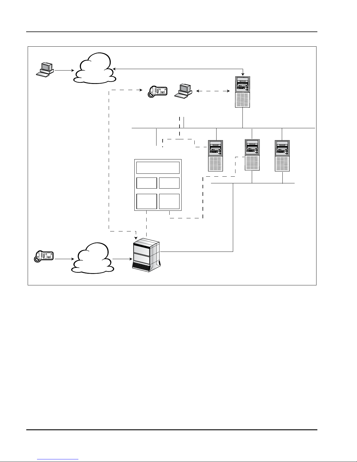
Knowledge worker architecture
In a knowledge worker environment, skill-based routing is not required. The
switch directs incoming calls to agents, and Communication Control Toolkit
delivers caller information, such as ANI/DNIS, or CLID.
In this environment, Communication Control Toolkit connects directly to the
switch over the ELAN subnet. It connects to client PCs and application servers
over the Nortel server subnet. The following diagram shows an overview of the
architecture of Communication Control Toolkit in a knowledge worker
environment:
Note: Solid lines show physical connections; dashed lines show logical
connections.
For a description of the components, see the preceding section.
Switch
Agent Desktop
with Communication
Control Toolkit
client application
CRM
Server
Contact Management
Framework
TAPI
Service
Provider
TAPI
Connector
Communication Control
Toolkit Server
PSTN
Telephone
Customer
Page 33

Planning and Engineering Guide 33
June 2007 Communication Control Toolkit architecture
Self-service architecture
In a self-service environment, callers use an IVR system, such as the MPS 500
or MPS 1000, to answer queries or request services. For example, bank
customers might use IVR to find out their account balance or to transfer funds.
Calls are not handled by agents.
In this environment, Communication Control Toolkit and the IVR server connect
to the switch through Symposium Call Center Server. Communication Control
Toolkit connects to the IVR system over the Nortel server subnet. The following
diagram shows an overview of the architecture of Communication Control
Toolkit in a self-service environment:
Switch
Agent Desktop
with Communication
Control Toolkit
client application
Symposium
Call
Center
Server
CRM
Server
Contact Management
Framework
IPML
Service
Provider
IPML
Connector
Communication Control
Toolkit Server
CLAN
ELAN
PSTN
IVR
Telephone
Customer
Page 34

34 Communication Control Toolkit
Communication Control Toolkit architecture Standard 5.01
Components
The Communication Control Toolkit introduces new components at the client,
transport, and server. The new client components simplify integration; the new
transport components provide firewall friendliness, Network Address
Translation (NAT), and Citrix support; and the new server components enable
open switch connectivity. Communication Control Toolkit also leverages
existing components of Telephony Application Program Interface (TAPI) and
Integration Package for Meridian Link (IPML).
The Communication Control Toolkit consists of Nortel-developed software and
third-party components, as described in the following sections.
Client application
Client applications are third-party components, and can include the following:
software phones
agent telephony toolbars with screen pop
intelligent call management applications
The Communication Control Toolkit API provides three levels of API that you
can use to develop a range of client applications.
An easy-to-use graphical API delivers Windows Form Controls (Win Forms),
which you can import into a project for rapid development of form-based
toolbars. The Win Forms provide graphical API abstractions that allow rapid
development of Communication Control Toolkit-enabled applications.
Page 35

Planning and Engineering Guide 35
June 2007 Communication Control Toolkit architecture
Transport
A secure transport layer, based on a single, reconfigurable port on the server
(default 29373), provides user authentication, digital signing (to prevent the
insertion of data), and encryption (to protect data transported across the
network). The Communication Control Toolkit client initiates communication
with the server through a socket. The server responds and continues to
communicate with the client through the same socket. This gives flexibility to
solutions requiring support for
Terminal Services support
firewall friendliness
NAT
Note: If you are using a firewall, you must ensure that this port is not blocked.
Communication Control Toolkit server
The component responsible for managing client sessions consists of the
following subcomponents:
Contact Management Framework—An infrastructure component that
manages the states of contacts, agents, terminals, and addresses.
TAPI Connector—An application that converts Communication Control
Toolkit requests to TAPI API calls, and TAPI events to Communication
Control Toolkit events. The TAPI Connector sits between the Nortel
Networks TAPI Service Provider and the Contact Management Framework.
TAPI Service Provider—A Microsoft TAPI client responsible for CTI
operations of all lines controlled by the Communication Control Toolkit
platform that have been initialized by TAPI.
IPML Connector—An application that allows you to deploy
Communication Control Toolkit in an IVR-only solution (where TAPI is
not used). The Contact Management Framework uses the IPML Service
provider to access the underlying switch interface (TLS).
IPML Service Provider—An IPML client responsible for CTI operations
of all lines controlled by the Communication Control Toolkit platform that
have been initialized by IPML. The IPML service provider operates as a
Page 36

36 Communication Control Toolkit
Communication Control Toolkit architecture Standard 5.01
service provider between the Contact Management Framework and the
Message Control Bus (MCB) on IPML.
Communication Control Toolkit API—An API that controls voice
resources. The API is published as Microsoft .NET types and distributed as
a Windows assembly, which is referenced by application developers.
Third-party applications
Third-party components include the following:
Microsoft .NET Framework (client and server)
Microsoft SQL Server 2000 Desktop Engine (MSDE 2000)
GigaSpaces Platform Infrastructure (server only)
Note: Third-party applications are supported according to the guidelines in the
Symposium Portfolio Server And Operating System Requirements document.
Switch interfaces
Communication Control Toolkit supports a number of different switch interfaces
that provide connectivity to different switch types.
Both the TAPI and IPML Service Providers support the Meridian Link Services
(MLS) interface. This is a two-way communications facility that provides the
interface between external computer applications and the switch to achieve
computer-telephony integration (CTI). Meridian Link Services is a protocol
exported as part of Communication Control Toolkit. An example of an MLS
application is an inbound telemarketing contact center, where MLS provides the
Calling Line ID (CLID) and Dialed Number Identification Service (DNIS)
information from an incoming call to a third-party application. The application
can use this information to retrieve data—both customer and product
information—from a database, and present it to the agent’s PC before the call is
even answered.
In addition, the TAPI Service Provider supports the Application Module Link
(AML) interface. This is the original interface created for communicating with
the switch, facilitating the functional integration of computer systems and
telecommunication systems.
Page 37

Planning and Engineering Guide 37
June 2007 Communication Control Toolkit architecture
The IPML Service Provider also supports the IVR-ASAI and IVR-GTS
interfaces, which provide connectivity to the Avaya G3 and Genesys T-Server
Release 10 switches, respectively.
.NET framework
Communication Control Toolkit provides a library of .NET types to be used in
developing applications.
The Microsoft .NET Framework is a managed execution environment that runs
on the Windows platform. This environment provides memory management,
strong type safety, version management, and high performance. The .NET
framework is made up of two components:
the Common Language Runtime (CLR), which provides
the execution environment
memory management
the .NET Framework class library, which includes
a set of .NET types (classes) that provide access to the underlying
operating system functions (including networking, security database
access, and so on)
additional .NET types that provide applications with communications
monitoring and control functionality
You can use this framework of classes to develop applications that run on
the Windows .NET platform. For these applications to run, you must install
the .NET Framework on the host operating system.
Distribution
The Communication Control Toolkit API is distributed as a .NET assembly.
Assemblies are self-describing: they contain all the type information for the
types they contain. Therefore, you only need to distribute the assembly. You do
not need to provide a separate file (for example, header file, type library, or IDL
file) for type information.
Page 38

38 Communication Control Toolkit
Communication Control Toolkit architecture Standard 5.01
Version management
The .NET framework supports versioning and side-by-side execution of
different versions of an assembly. Therefore, if a second version of an assembly
is released, both versions of the assembly can run in parallel. This allows
multiple generations of the Communication Control Toolkit client applications
to execute simultaneously on a client.
Supported programming languages
As .NET types, the Communication Control Toolkit API is accessible from any
.NET programming language (there are currently over 20 programming
language compilers for the .NET Framework, including the Microsoft compilers
for C#, C++, Visual Basic, and J#).
Page 39

Planning and Engineering Guide 39
June 2007 Communication Control Toolkit architecture
Communication Control Toolkit API
application types
Communication Control Toolkit provides three types of API:
Full API
Lite API
Graphical API
These APIs can be used to develop applications that run on the .NET platform.
The following table shows the types of applications that can be created with each
type of API:
Full API
The Full API is an object-oriented API that provides a powerful, object-oriented
programming interface to developers. It is used by developers with
Communication Control Toolkit knowledge who want to develop complex
applications. The API exposes as many features of the underlying
communications platforms as possible.
Primary objects
The Full API allows you to control the following types of objects:
Session—A representation of a user’s active session with Communication
Control Toolkit. It is the main entry point and provides access, directly or
indirectly, to all other objects. It provides users with a view of the subset of
Application type Full API Lite API
Graphical
API
Windows UI applications
✔✔
✔
Console (text-based) applications
✔✔
Windows Service applications
✔✔
Web applications
✔✔✔
Page 40

40 Communication Control Toolkit
Communication Control Toolkit architecture Standard 5.01
communications devices and functionality that they have permission to
access.
Contact—The abstraction of a communication (for example, a phone call).
A contact may have one or more connections.
Terminal—A physical (or logical) endpoint, such as a telephone. It may be
associated with one or more addresses.
Address—The representation of an addressable endpoint, such as a DN,
position ID, or CDN. An address may be associated with one or more
terminals.
Connection—A relationship between an address and a contact (for
example, a leg of a phone call).
TerminalConnection—A relationship between a terminal and a connection
(for example, a representation that a leg of a phone call is connected to a
particular telephone).
Agent—A user who is logged on to one or more contact distribution queues
for the purposes of receiving queued or routed contacts.
AgentTerminalSession—The representation of the relationship between the
agent and a terminal (for example, an agent is logged on to a contact center
skillset at a particular telephone).
Lite API
The Lite API provides a programming interface that hides the complexity of the
underlying communications platforms, thus enabling rapid application
development of simpler Communication Control Toolkit applications. It is
particularly useful to application developers who want to focus on the business
application and who only require basic functionality.
The Lite API provides a subset of the capabilities of the Full API and requires
less Communication Control Toolkit knowledge and code development to create
basic Communication Control Toolkit applications.
Page 41

Planning and Engineering Guide 41
June 2007 Communication Control Toolkit architecture
Graphical API
The Graphical API abstracts the Full API to a basic button-level of complexity
for developers who do not want to use the Full or Lite API and who require a
graphical user interface-based business application. With the Graphical API,
developers can create applications by dragging and dropping icons using Visual
Studio .NET 2003.
The Graphical API includes a set of Windows Form controls.
Supported functions
The Graphical API supports the following functions:
Answer an existing contact
Call supervisor
Conference in a supervisor under emergency circumstances
Create a new contact
Drop an existing contact
Generate DTMF tones on an existing contact
Hold and take off hold an existing contact
Initiate and complete a conference
Initiate and complete a consult transfer
Login and logout an agent
Perform a blind transfer on an existing contact
Place an agent into a ready and not ready state with a reason code
Place an agent into a ready and not ready state
Place the phoneset into a busy state and a ready state
Set activity codes
Set contact data
Page 42

42 Communication Control Toolkit
Communication Control Toolkit architecture Standard 5.01
Windows Forms Controls
As developers design and modify the user interface of their solutions, they add,
align, and position controls. Controls are objects that are contained within form
objects. Each type of control has its own set of properties, methods, and events
that make it suitable for a particular purpose. Windows Forms controls are
reusable components that encapsulate user interface functionality and are used
in client-side Windows applications.
Windows Forms controls include buttons, text boxes, check boxes, and so on.
Communication Control Toolkit custom Windows Form Controls are all based
on an existing Windows Form Control, the basic Button
(System.Windows.Forms.Button).
Communication Control Toolkit contains the following Windows Form
Controls:
Custom control Description
SessionStatesCtrl Session state and event computer control
SessionLoginCtrl Session login and logout control
SessionReadyCtrl Session Ready and Not Ready control
ContactMakeCtrl Make Contact control
ContactAcceptCtrl Accept Contact control
ContactReleaseCtrl Release Contact control
ContactHoldCtrl Put Contact on Hold, take Contact off hold
ContactTransferCtrl Consultative Transfer of Contact control
ContactBlindTransCtrl Blind Transfer of Contact control
ContactConfCtrl Conference Contact control
Page 43

Planning and Engineering Guide 43
Chapter 3
Engineering Communication Control
Toolkit
In this chapter
Section A: Engineering the server 45
Section B: Engineering the client 59
Page 44

44 Communication Control Toolkit
Engineering Communication Control Toolkit Standard 5.01
Page 45

Planning and Engineering Guide 45
June 2007 Engineering Communication Control Toolkit
Section A: Engineering the server
In this chapter
Hardware requirements 46
Operating system configuration requirements 50
Capacity 51
Guidelines to minimize capacity requirements 56
Page 46

46 Communication Control Toolkit
Engineering Communication Control Toolkit Standard 5.01
Hardware requirements
Supported hardware platforms
Communication Control Toolkit Release 5.0 is a software-only solution, which
operates on any hardware platform that meets specified requirements. This
solution is referred to as Platform Vendor Independence (PVI).
Platform Vendor Independence
Communication Control Toolkit does not require Nortel-supplied hardware. It
runs on any hardware platform with
an Intel Pentium CPU
Windows 2000 Server, Windows 2000 Advanced Server, or Windows
Server 2003 (Standard Edition or Enterprise Edition) operating system and
Microsoft-certified drivers. For minimum Service Pack levels, see the
Symposium Portfolio Server And Operating System Requirements.
CPU speed, RAM, hard drive capacity, and hard drive speed that satisfies
the capacity requirements of the contact center
One or more network interface cards (NICs) is also required, depending on the
type of environment. For more information, see Chapter 5, “Engineering the
network.”
For more detailed information about server requirements, see the Symposium
Portfolio Server And Operating System Requirements.
CPU requirements
Communication Control Toolkit requires a processor from the Intel Pentium
suite. For optimal performance, average CPU utilization should not exceed 70
percent for any 20-minute period.
Note: It is expected and normal for CPU utilization to exceed 70 percent (with
utilization as high as 100 percent) for short periods.
Page 47

Planning and Engineering Guide 47
June 2007 Engineering Communication Control Toolkit
As the number of agents, number of resources, and call loads increase, the speed
of the processor required to maintain average CPU utilization below 70 percent
also increases.
Hard disk requirements
Communication Control Toolkit requires at least 2 Gb of hard disk space for
installation. The Communication Control Toolkit installer requires a minimum
of 128 Mb free on the C:\ drive, regardless of the location of the target
installation drive. This is because the installer requires a temporary directory on
the C:\ drive from which to work.
When you install the Nortel Communication Control Toolkit server, you must
ensure that you have enough space allocated for the Nortel Communication
Control Toolkit database. The Nortel Communication Control Toolkit database
is installed on the default drive in the Program Files\Microsoft SQL
Server\MSSQL$VCNNCCTDB directory. You must have a minimum of 68.1
Mb in this directory to install the Nortel Communication Control Toolkit
database; however, the database can reach a maximum size of 2 GBytes.
Memory requirements
RAM requirements
Communication Control Toolkit requires at least 1 Gb of RAM. Additional
RAM may be required for systems with a greater workload.
To determine whether the amount of memory on your platform is adequate for
your workload, use the Windows Performance Monitor. During steady state
operation, the average value of the pages per second counter for a 20-minute
period should not exceed 5. If it does, increase RAM and adjust the paging file
size (see “Paging file” on page 48).
You can use more than the recommended amount of RAM, but if you do, you
must allow additional disk space to accommodate the increase in size of the
paging file (see the following section).
Page 48

48 Communication Control Toolkit
Engineering Communication Control Toolkit Standard 5.01
Paging file
The following table shows the default paging file sizes set during the Windows
installation:
For a system with 512 Mb of RAM, the default minimum paging file size is 768
Mb and the default maximum paging file size is 1 Gb. To optimize performance,
however, Microsoft recommends that the minimum paging file size equal the
maximum paging file size. Therefore, Nortel recommends that both the
minimum and maximum paging file sizes be set to 1.5 * RAM (or 768 Mb, for
the preceding example).
If any of the following conditions apply, the default system complete memory
dump is not generated when the system stops unexpectedly:
You are using multiple paging files distributed over separate disks.
The paging file is not located on the system boot drive (C: drive).
Physical RAM size is larger than 2 Gb.
To ensure that a complete system memory dump can be generated, Nortel
recommends that
the paging file size not exceed 2 Gb
the paging file reside on the C: partition
Modems
Communication Control Toolkit does not run on a server with a modem
connected. Therefore, do not install a modem on the Communication Control
Toolkit server. To enable remote support for the server, set up a Remote Support
VPN (see Chapter 6, “Setting up remote support with a VPN”).
Server RAM size
Minimum paging file
size
Maximum paging file
size
Less than 2 Gb 1.5*RAM 2*RAM
2 Gb or greater 2 Gb 2 Gb
Page 49

Planning and Engineering Guide 49
June 2007 Engineering Communication Control Toolkit
Server location
The physical location of the Communication Control Toolkit server depends on
the type of connection you require. In a contact center or self-service
environment, the server must be collocated with Symposium Call Center Server.
In a knowledge worker environment, the server must be collocated with the
switch.
Backup, disaster recovery, and solution redundancy
A backup tape drive is not a requirement for Communication Control Toolkit.
You can use a hardware-RAID solution provided it does not have a negative
impact on TAPI performance. If you encounter issues with a hardware-RAID
solution, refer them to the RAID vendor.
Note: Software-RAID solutions, such as the one available from Microsoft, are
not supported.
If you require a hardware-redundant solution, it must be tested by one of the
following:
verification testing by a Nortel Packaged Services group
compatibility testing via the Nortel Developer Program
For information, refer to your Nortel representative or visit the Nortel developer
program web site at
http://www.nortel.com/developer
Note: Communication Control Toolkit does not support Microsoft clustering
because the software is currently not cluster-aware.
Page 50

50 Communication Control Toolkit
Engineering Communication Control Toolkit Standard 5.01
Operating system configuration requirements
Domain considerations
The server cannot be a domain controller. It can be a stand-alone server within a
domain.
Remote Access Services
Communication Control Toolkit does not run on a server with RAS configured
or with a modem connected. Therefore, do not configure Remote Access
Services (RAS) or install a modem on the Communication Control Toolkit
server.
Notes:
If Remote Access Services is installed, the service must be in disabled state.
Remote support with a directly connected modem is not possible. Nortel
recommends a Remote Support VPN be implemented for Communication
Control Toolkit (see Chapter 6, “Setting up remote support with a VPN”).
Page 51

Planning and Engineering Guide 51
June 2007 Engineering Communication Control Toolkit
Capacity
Factors affecting performance
The performance of the Communication Control Toolkit server depends on a
number of factors, including
number of resources (terminals, addresses, and users)
number of clients
number of calls per hour, call duration, and call complexity—Transfers,
conferencing, and attached caller-entered data all increase call complexity,
and, therefore, the resources required to process a call.
amount of call-attached data (see the following section)
hardware configuration (processor speed, memory, and disk space
available)—For more information about hardware platforms, see
“Hardware requirements” on page 46.
the type of solution (TAPI, IPML, or both)—A system running both TAPI
and IPML requires more system resources than a system running only TAPI
or IPML.
debugging and logging activities
Call-attached data
The amount of data attached to a call has a significant impact on performance.
Attached data that affects performance includes both TAPI data and IVR data.
Communication Control Toolkit handles a maximum of 4096 bytes of attached
data (TAPI + IVR) per call. The default call data size allowed per call is 512
bytes. To optimize performance, use the Communication Control Toolkit snap-in
utility to set the call data size to match your actual call data requirements (for
detailed instructions, see the Installation and Maintenance Guide). If the call
data size is set higher than your requirements, performance suffers because
unnecessary memory is allocated for each call.
Page 52

52 Communication Control Toolkit
Engineering Communication Control Toolkit Standard 5.01
Debugging activities
There are four main logging sections in Communication Control Toolkit 5.0:
Communication Control Toolkit Server logging
Communication Control Toolkit Connector logging
Snap-in logging
Data Access Layer logging
Each section has a number of logging levels:
Communication Control Toolkit Server logging
Trace Service Provider Events
Trace Client Session Events
Trace CMF Events
Enable Debug Logging
Communication Control Toolkit Connector, Snap-in, and Data Access
Layer logging
Ve rb o se
Information
Warning
Error
Critical
The logging level of each section is independent: you can set the logging level
for the Snap-in to Verbose and the logging level for the Connector to Critical.
You configure logging levels using the Communication Control Toolkit
Configuration Tool.
If the logging level is set to then these message levels are output
Ve rb o se A ll
Warning Warning, Error, and Critical
Error Error and Critical
Page 53

Planning and Engineering Guide 53
June 2007 Engineering Communication Control Toolkit
Messages are output to the Communication Control Toolkit Logging Utility,
CCTDBM.exe.
Each Communication Control Toolkit main component (Communication
Control Toolkit, Communication Control Toolkit Connector, Communication
Control Toolkit Snap-in, and Communication Control Toolkit Data Access
Layer [DAL]) outputs to its own instance of the Communication Control Toolkit
Logging Utility. Therefore, if logging is enabled only for Communication
Control Toolkit Connector, then only one instance of the Communication
Control Toolkit Logging Utility runs. However, if logging is enabled for all of
the four main components, then four instances of the Communication Control
Toolkit Logging Utility run, one for each section.
The Communication Control Toolkit Logging Utility can store messages to a
file; it can write messages to the screen without saving them to file; or it can
write messages to both the screen and a file.
The Communication Control Toolkit Logging Utility consumes Communication
Control Toolkit server CPU. CPU utilization increases as the number of
messages output increases.
To reduce CPU utilization, follow these guidelines:
Log only to a file. Logging to the screen and to a file is fine at low call rates,
but as the call rate increases, this process consumes more and more CPU
resources. Logging to the screen is CPU-intensive, and as messages cannot
be read at high call rates (they scroll too quickly), it is better to log directly
to a file in these circumstances.
Only enable logging for relevant sections. For example, if you are writing a
Communication Control Toolkit client application, then you only need to
enable logging for the Communication Control Toolkit server.
Always use the appropriate logging level. For example, if you are writing a
Communication Control Toolkit client application, then you only need to
enable the Trace Service Provider Events and Trace Client Session Events
levels for the Communication Control Toolkit server.
Critical Critical
If the logging level is set to then these message levels are output
Page 54

54 Communication Control Toolkit
Engineering Communication Control Toolkit Standard 5.01
You must provision your server for the use of the Communication Control
Toolkit Logging Utility application at peak times, with all applications running,
without exceeding the 70 percent CPU utilization guideline.
Contact center capacity limits
Call capacity
36 000 simple CPH with no call data to a maximum for 2000 agents or
24 000 CPH with call data attached to a maximum of 1600 agents
Self service supports an additional 16 000 CPH running on the IVR lines
Agent counts
2000 agents (2000 terminals, 4000 addresses) if call data is not required or
1600 agents (1600 terminals, 3200 addresses) if call data is used.
Self service supports an additional 480 IVR lines
Knowledge worker - direct connect capacity limits
Call capacity
36 000 simple cph for combined Communication Control Toolkit and TAPI
clients
Agent counts
2000 agents (4000 addresses) for combined Communication Control Toolkit and
TAPI clients
Self service capacity limits
Call capacity
16 000 cph for combined IVR ports and agent desktop
Agent counts
480 combined IVR lines and agent desktops
Page 55

Planning and Engineering Guide 55
June 2007 Engineering Communication Control Toolkit
Note: A basic call is defined as an incoming call that is answered by an agent,
and then (when talk time is complete) released.
MLS performance impact
MLS is used in a contact center environment. It is an intelligent signaling link
offering computer-telephony integration (CTI) applications access to
Meridian 1/Succession 1000 call processing functions.
If you are using Meridian Link Services (MLS) with Communication Control
Toolkit, there is an impact on Symposium Call Center Server performance. For
more information, refer to the Symposium Call Center Server Planning and
Engineering Guide.
Page 56

56 Communication Control Toolkit
Engineering Communication Control Toolkit Standard 5.01
Guidelines to minimize capacity requirements
The engineering models used to calculate the capacity requirements of your
contact center assume that you follow certain guidelines to minimize the load on
your server.
Steady state operation
Steady state refers to an operational state in which average values of the capacity
parameters do not change with time. For example, CPU utilization may vary
widely at different consecutive time instances; however, if we examine the
average values of CPU utilization taken over consecutive 20-minute intervals,
during a period of steady state operation, these average values are approximately
the same.
Guidelines for steady state operation
To ensure trouble-free operation of the server, adhere to the following guidelines
for steady state operation:
Processor CPU: Average CPU utilization over any 20-minute period
during the peak hour under steady state operation must not exceed 70
percent.
Server RAM memory: Average pages per second (found in the Memory
Object of the Performance Monitor) over any 20-minute period during the
peak hour under steady state operation must not exceed 5.
Server virtual memory: Committed Bytes (found in the Memory Object of
the Performance Monitor) must not exceed 90 percent of the Commit Limit
(also found in the Memory Object of the Performance Monitor).
Physical and virtual memory: For optimal performance, you must adhere
to the Microsoft recommendations for physical RAM and virtual memory
sizing. For more information, see “Memory requirements” on page 47.
Nortel server subnet traffic: Average Nortel server subnet utilization must
not exceed the limit specified on page 103 (for a contact center or selfservice environment), or on page 93 (for a knowledge worker environment).
Page 57

Planning and Engineering Guide 57
June 2007 Engineering Communication Control Toolkit
ELAN subnet traffic: In a knowledge worker environment, average ELAN
subnet utilization must not exceed the limit specified on page 94.
Note: Communication Control Toolkit provides a number of import utilities. Do
not use these utilities while the Communication Control Toolkit server is
operating in a steady state. Use them only during initial configuration of the
Communication Control Toolkit server or when the Communication Control
Toolkit server is offline.
Guidelines for non-steady state operations
A number of non-steady state processes can have a significant impact on the
steady state call processing activity of the server. To minimize their impact,
Nortel recommends a number of restrictions:
All non-steady state processes
Run only one non-steady state process at any given time.
Database backup
Perform database backups during off-peak hours.
Checking files for viruses
Perform this activity during off-peak hours. For more details, see the
Symposium Portfolio Server And Operating System Requirements
document, available on the Partner Information Center (PIC) web site.
Note: Communication Control Toolkit provides a number of import utilities.
These utilities must not be used while the Communication Control Toolkit server
is operating in a steady state. They may only be used during initial configuration
of the Communication Control Toolkit server or when the Communication
Control Toolkit server is offline.
When using the TAPI Configuration Tool to do a Data Import from the switch
dump, make sure that the following services are stopped:
ACDProxy
Telephony Service
When using any of the import utilities in the Communication Control Toolkit
snap-in to import resources into Communication Control Toolkit, make sure that
the following services are stopped:
Page 58

58 Communication Control Toolkit
Engineering Communication Control Toolkit Standard 5.01
NCCT Server
NCCT TAPI Connector Service (if installed)
Nortel Networks MPS Manager (if installed)
Nortel Networks RSH Daemon (if installed)
Page 59

Planning and Engineering Guide 59
June 2007 Engineering Communication Control Toolkit
Section B: Engineering the client
In this section
Client requirements 60
Page 60

60 Communication Control Toolkit
Engineering Communication Control Toolkit Standard 5.01
Client requirements
It is the responsibility of the application developer to specify the requirements of
the Communication Control Toolkit client PC. Communication Control Toolkit
clients must meet the following minimum requirements.
Operating system
Communication Control Toolkit supports applications running on a PVI client
running one of the following operating systems:
Microsoft Windows 2000 Professional
Microsoft Windows XP Professional
Windows Server 2003
Microsoft Windows Vista
Hardware requirements
The client PC must meet the minimum requirements of the operating system.
Port requirements
Communication Control Toolkit clients use a single port for communication
with the server. By default, this port is 29373; however, the port number is
configurable (for detailed instructions, see the Installation and Maintenance
Guide).
If you are using a firewall, ensure that this port is open.
Page 61

Planning and Engineering Guide 61
Chapter 4
Engineering the switch
In this chapter
Section A: Engineering Meridian 1/Succession 1000 63
Section B: Configuring Meridian 1/Succession 1000 73
Page 62

62 Communication Control Toolkit
Engineering the switch Standard 5.01
Page 63

Planning and Engineering Guide 63
June 2007 Engineering the switch
Section A: Engineering Meridian 1/
Succession 1000
In this section
Meridian 1/Succession 1000 switch requirements 64
Meridian 1/Succession 1000 switch capacity 67
Supported phonesets 70
Page 64

64 Communication Control Toolkit
Engineering the switch Standard 5.01
Meridian 1/Succession 1000 switch
requirements
Supported switches
Communication Control Toolkit requires one of the following types of switches:
Meridian 1 Options 11C, 11C Mini, 51C, 61C, 81, and 81C
Succession 1000 and 1000M
Switch software versions
Communication Control Toolkit requires one of the following versions of switch
software:
X11 Release 25.40B or greater
Succession 1000, Release 2.0
Succession 1000M, Release 3.0
These are the minimum releases of switch software required for Communication
Control Toolkit 5.0. Some Communication Control Toolkit features require a
more recent switch software version. To use the DTMF and UUI features, you
need the following releases of switch software:
X11 Release 26.07
Succession 1000M, Release 3.0
Page 65

Planning and Engineering Guide 65
June 2007 Engineering the switch
Applications
Required applications
The following table lists the applications that must be installed on a Succession
switch in order to support Communication Control Toolkit in a contact center,
knowledge worker, or self-service environment:
Optional applications
The following table lists additional applications that can be installed, depending
on the level of functionality required:
Application
(option) Purpose
Contact
center
Knowledge
worker
Self-
service
35 Integrated messaging (IMS)
✔✔ ✔
77 Command and status link (CSL)
✔✔ ✔
153 ISDN/AP for third parties (IAP 3P)
✔✔
247 Call ID
✔✔
311 NGCC mixed generation call center
✔✔
324 NGen new generation foundation
✔✔
Application
(option) Purpose
40 Basic ACD
41 Basic ACD B
42 Basic ACD 3 usage reports
43 Basic ACD C2 load management
45 Basic ACD A
50 ACD D used for ACD MAX applications
145 Integrated services digital network (ISDN)
Page 66

66 Communication Control Toolkit
Engineering the switch Standard 5.01
Networked ACD
The usage of Networked ACD (NACD) is transparent to Communication
Control Toolkit. The call rates used in Communication Control Toolkit
engineering are the total calls arriving to Communication Control Toolkit from
the local switch, either directly or from Networked ACD.
ISDN
The ISDN circuits to the PSTN must be provisioned to handle the network call
traffic to and from each switch. It is assumed that these circuits are provisioned
in a similar manner to that of NACD.
146 Primary rate access (PRA)
214 Enhanced ACD routing (EAR)
215 Customer controlled routing (CCR)
Application
(option) Purpose
Page 67

Planning and Engineering Guide 67
June 2007 Engineering the switch
Meridian 1/Succession 1000 switch capacity
The capacity of Communication Control Toolkit is a factor not only of
Communication Control Toolkit itself but also of the physical capacity of the
switch. The call throughput of Communication Control Toolkit depends on the
following factors:
rated capacity of the switch
call complexity
expected call rate
You can use the M1 Switch Capacity Spreadsheet to calculate call throughput
for the Meridian 1/Succession 1000 switch. (This spreadsheet is available from
the Partner Information Center [PIC] web site.)
Rated capacity of the switch
The capacity of the switch is specified as the number of Equivalent Basic Calls
(EBCs) per hour. An EBC is a measure of the switch CPU real time required to
process a Basic Call. A Basic Call is defined as a simple unfeatured call between
two 2500 sets, on the same switch, using a four-digit dialing plan.
The EBC capacity of the switch depends on the processor type, as shown in the
following table:
Processor type EBC capacity
Option 11C/CSE 1000 42 000 (TDM mode)
35 000 (IP-enabled mode)
CP2 54 782
CP3 72 000
CP4 100 800
CPP 315 000
Page 68

68 Communication Control Toolkit
Engineering the switch Standard 5.01
Notes:
For more information on switch application engineering, see the Large
System Planning and Engineering Guide (NTP 553-3021-120).
CP2 is not supported by Meridian 1 in IP-enabled mode, or by Succession
1000M, Release 3.0.
Call complexity
The complexity of a call is defined as the number of each type of service used by
the call. All calls have an EBC cost, with calls of higher complexity (that is,
using a greater number of services) costing more EBCs.
For example, a basic call costs 2.40 EBC; Give Music costs 0.25 EBC; Give IVR
(including transfer) costs 2.29 EBC. Therefore, a call that receives IVR and
Music treatments costs
2.40 + 0.25 + 2.29 = 4.94 EBC
To quantify levels of call complexity, Nortel has defined several call models,
which represent simple, complex, and front-end IVR systems (see AppendixC,
“Standard call models”). You can calculate the EBC cost using the Meridian 1
Switch Capacity Spreadsheet, which is available on the PIC web site.
Maximum achievable call rates
To determine the maximum achievable call rates for different switch models, all
contributions resulting from the following parameters must be considered:
the call complexity
the MLS commands issued by CTI applications
any other applications that may be communicating over the ELAN with the
switch
You can determine the call rate by calculating the total Equivalent Basic Call
(EBC) value for all incoming traffic per switch type.
Page 69

Planning and Engineering Guide 69
June 2007 Engineering the switch
Sample calculations using the Meridian 1 switch Capacity Tool
This calculation considers the Meridian 1 Option 81 with a CPP processor,
which has an EBC capacity of 315 000.
CPP utilization per number of active agents per call model
For a description of the call models, see Appendix C, “Standard call models.”
This table implies that if there are 44 000 Symposium Voice Processing type
calls, then the CPP uses 193 percent of the processor capacity. In contrast, the
Front-end IVR call model uses only 76 percent of the CPP for an equivalent call
rate.
Note: Nortel does not recommend CPU utilization greater than 100 percent.
Active agents 2200 1500
Calls per hour 44 000 30 000
Symposium Voice Processing 193% 131%
Hybrid 123% 84%
Front-end IVR 76% 51%
Page 70

70 Communication Control Toolkit
Engineering the switch Standard 5.01
Supported phonesets
Communication Control Toolkit monitors and controls the telephony activities
of the following telephones that are registered on a supported switch:
M2000 series digital telephones:
M2009
M2018
M2317
Meridian modular telephones (MMT):
M2006
M2008
M2216
M2616
M39xx telephones:
M3901
M3902
M3903
M3904
M3905
IP phones and softphones
IP Phone 2004
IP Phone 2002
ATTENTION
If your telephone set supports Auto Hold Allowed (AHA),
Multiple Appearance Reduction Prime (MARP), or Multiple
Appearance Directory Number (MADN), you must disable the
configurations. These configurations are not supported in
Communication Control Toolkit 5.0. For more information
about unsupported telephone configurations, see the
Communication Control Toolkit Installation and Maintenance
Guide.
Page 71

Planning and Engineering Guide 71
June 2007 Engineering the switch
IP Phone 2001
IP Softphone 2050
Page 72

72 Communication Control Toolkit
Engineering the switch Standard 5.01
Page 73

Planning and Engineering Guide 73
June 2007 Engineering the switch
Section B: Configuring Meridian 1/
Succession 1000
In this section
Overview 74
Configuring the ELAN subnet (knowledge worker environment) 75
Configuring CDNs 81
Configuring TAPI phonesets 83
Page 74

74 Communication Control Toolkit
Engineering the switch Standard 5.01
Overview
The following checklist lists the tasks required to configure the switch for
Communication Control Toolkit:
Description ✔
Configure the ELAN hardware and software. See “Configuring the
ELAN subnet (knowledge worker environment)” on page 75.
Note: In a contact center environment, the ELAN is configured
during installation and configuration of Symposium Call Center
Server.
Configure CDNs to be controlled by Communication Control
Toolkit. See “Configuring CDNs” on page 81.
Configure phonesets for use with TAPI. See “Configuring TAPI
phonesets” on page 83.
Configure IVR ports, ACD queues, and phonesets for use with
IPML. See the IPML Distributor Software Installation Guide.
Page 75

Planning and Engineering Guide 75
June 2007 Engineering the switch
Configuring the ELAN subnet (knowledge
worker environment)
If you are installing Communication Control Toolkit in a contact center
environment, Communication Control Toolkit communicates with the switch
through Symposium Call Center Server. To configure the connection between
Symposium Call Center Server and the switch, refer to the Symposium Call
Center Server documentation.
If you are installing in a knowledge worker environment, you must configure the
ELAN subnet on the switch. Configuration of the ELAN subnet involves
configuration of both the hardware and the software.
Notes:
The Communication Control Toolkit server requires two 10/100BASE-T
network Ethernet ports, one connecting to the ELAN subnet and the other
connecting to the Nortel server subnet. The Nortel server subnet card
should always be first in the binding order. NetBios should be disabled on
the NIC connected to the telephony switch (ELAN subnet NIC), since
NetBios traffic does not work well on multi-homed hosts as it is not a
routable protocol.
Applications connect to the Nortel server subnet using the IP address of the
Ethernet port on the switch and port number 8888. The switch dynamically
assigns the appropriate Nortel server subnet address for each application.
Configuring the hardware
You must connect the switch network port to the Nortel server subnet. Refer to
the product documentation provided with your switch for instructions on
hardware configuration.
Configuring the software
When you complete the hardware configuration of the Ethernet port, perform the
following tasks to configure the software:
Page 76

76 Communication Control Toolkit
Engineering the switch Standard 5.01
1. Assign an IP address to the switch.
2. Define a routing table.
3. Define the Embedded LAN (ELAN) and a Value Added Server (VAS).
4. Enable the ELAN link.
5. Check the ELAN link.
The latter three tasks associate the link (ELAN) with a VAS ID to allow message
transmission.
Assigning an IP address to the switch
To assign an IP address for an Ethernet port, log on to the switch through
Optivity Telephony Manager (OTM). Use the following sample session as a
template, substituting relevant values where appropriate in overlay 117:
> LD 117
NEW HOST M1SERVER_A 47.1.1.10
where M1SERVER_A is the host name for the IP address and 47.1.1.10 is the IP
address of the active Ethernet port.
CHG ELNK ACTIVE M1SERVER_A
CHG MASK 255.255.255.0
where 255.255.255.0 is the local subnet mask.
In a redundant system with a dual CPU, repeat this process for the backup
inactive CPU, using the following template and substituting appropriate values
where necessary:
> LD 117
NEW HOST M1SERVER_B 47.1.1.11
where M1SERVER_B is the host name for the IP address and 47.1.1.11 is the IP
address of the standby Ethernet port.
CHG ELNK INACTIVE M1SERVER_B
Page 77

Planning and Engineering Guide 77
June 2007 Engineering the switch
After you assign the necessary IP address(es), press the <MAN INT> button on
the CPU card to manually initialize the system and activate the new IP address
information.
Defining a routing table
The routing table supplies the switch with the IP addresses of a gateway server.
This information allows the switch to send return messages to the gateway for
forwarding to the requesting client. If you have a default gateway in the network,
use the following sample session as a template, substituting relevant values
where appropriate:
> LD 117
NEW ROUT 0.0.0.0 47.1.1.250
where 47.1.1.250 is the IP address of the default gateway.
Primary IP address procedures
This section provides procedures for the activation, validation, and recovery of
the Primary IP address.
Activation procedure
Manually initialize the system to activate the connection to the IP address
configured in overlay 117.
Note: You must perform a manual initialization to establish the initial
connection to the primary IP address. After the connection is established,
another manual initialization is required only if the primary IP address is
changed.
Validation procedure
To verify that the primary IP address is active, compare the IP address
configured in overlay 117 with the IP address used in overlay 137. The IP
addresses must be identical in both overlays. To perform the validation, use the
following sample as a template, substituting relevant values where appropriate:
> LD 117
Page 78

78 Communication Control Toolkit
Engineering the switch Standard 5.01
OAM000
PRT ELNK
ACTIVE ETHERNET: PRIMARY_IP 47.48.49.50
INACTIVE ETHERNET: SECONDARY_IP 47.48.49.51
OK
>
LD 137
CIOD000
STAT ELNK
ELNK ENABLED
Ethernet (ln unit number 0):
Host: PRIMARY_IP Internet address: 47.48.49.50
where 47.48.49.50 indicates the actual IP address used.
Broadcast address: 47.48.49.255
Ethernet address: 00:00:75:32:1e:ca
Netmask: 0xff000000; Subnetmask: 0xfffff000
33520 packets received; 12308 packets sent
0 input errors; 0 output errors
0 collisions
If the IP addresses are not identical, the IP address is invalid and you must
perform the recovery procedure.
Recovery procedure
If the connection to the Primary IP address is lost, you can reestablish it by
performing the following tasks:
Page 79

Planning and Engineering Guide 79
June 2007 Engineering the switch
1. Manually initialize the system to reestablish a connection to the primary IP
address.
2. Perform the validation procedure again to confirm that the Ethernet
connection is fully functional.
To define the ELAN subnet with LD 17
Use these prompts and responses in Overlay 17.
Note: For prompts that are not specified in the following table, press Enter.
Prompt Response Description
REQ CHG Change
TYPE CFN Configuration Record
ADAN NEW ELAN 16,
CHG ELAN 16,
OUT ELAN 16
Add/change/remove
I/O device type ELAN 16 (AML over
Ethernet).
CTYP ELAN Card type
DES NAME Enter a name for the ELAN port number.
Use a generic name because the ELAN port
is not dedicated to a specific application.
VAS NEW Add a value added server.
VSID 16 VAS identifier
ELAN 16–31 Associate VAS ID with the ELAN.
SECU Yes Turn on security for MLS applications.
CSQO 255 maximum Number of call registers linked to output
queue
CSQI 255 maximum Number of call registers linked to input
queue
REQ END Exit from overlay.
Page 80

80 Communication Control Toolkit
Engineering the switch Standard 5.01
To enable the ELAN subnet link
1 At the switch administration terminal, load LD 48.
2 Type the command ENL ELAN 16.
Checking the ELAN subnet with LD 48
Once you configure the VSID and power up Communication Control Toolkit,
the ELAN link comes into service. Follow these steps to check the ELAN link:
1 At the switch administration terminal, load LD 48.
2 Type the command STAT ELAN.
3 Ensure that, under your Communication Control Toolkit ELAN IP address,
LYR7 and APPL are active. Note the ELAN ID.
Example
ELAN #: 16 DES: the application (for example, elan16)
APPL_IP_ID: 47.152.163.68 LYR7: ACTIVE EMPTY APPL
ACTIVE
4 If the ELAN is not active, check the ELAN connection by pinging the switch
IP address from the application. To do so, open a DOS prompt. Type ping
nnn.nnn.nnn.nnn
where nnn.nnn.nnn.nnn is the switch IP address, and
then press Enter.
Page 81

Planning and Engineering Guide 81
June 2007 Engineering the switch
Configuring CDNs
CDNs are specialized ACD-DNs or queues on the switch. Communication
Control Toolkit can control CDNs that are not controlled by Symposium Call
Center Server (only one application can control a CDN). However,
Communication Control Toolkit can monitor CDNs controlled by other
applications, such as Symposium Call Center Server.
You must configure CDNs on the switch, as well as in the Communication
Control Toolkit snap-in utility. This section describes how to configure CDNs
controlled by Communication Control Toolkit on the switch.
Note: To monitor a CDN controlled by Symposium Call Center Server,
configure the CDN as described in the Symposium Call Center Server
documentation. Then, configure the DN in the Communication Control Toolkit
Configuration Tool, making sure that the DN Monitor box is checked.
Assumptions
The following assumptions are made:
You know the user ID and password to log on to the switch administration
terminal.
You are familiar with switch Change and Diagnostics overlays.
You have a listing or printout of available CDNs (overlay program 23).
VSID definitions
Do not enter a VSID definition on CDNs.
Page 82

82 Communication Control Toolkit
Engineering the switch Standard 5.01
To configure a CDN with LD 23
Use these prompts and responses in Overlay 23. For prompts that are not
specified in the following table, press Enter.
What next?
You must also configure the CDN in the TAPI Configuration Tool (see the
Installation and Maintenance Guide). Ensure that the DN Monitored box is
checked.
You must configure the CDN as a route point address in the
Communication Control Toolkit Configuration Tool (see the Installation
and Maintenance Guide).
When developing your application, use the appropriate API call to acquire
the CDN.
Prompt Response Description
REQ NEW Add a CDN.
TYPE CDN Control DN data block
CUST 0–99 Customer number
CDN xxxx Control Directory Number
RPRT No Deactivate the report control option.
DFDN xxx(xxxx) Default ACD-DN. The ACD-DN to which the
call is routed if there is a problem on
Communication Control Toolkit.
CNTL Yes DN is controlled by Communication Control
Toolkit.
REQ END Exit from overlay.
Page 83

Planning and Engineering Guide 83
June 2007 Engineering the switch
Configuring TAPI phonesets
Guidelines
Use Overlay 11 to configure phonesets for use with Communication Control
Toolkit. Follow these guidelines:
Set the AST value for the phoneset to the key to be monitored by TAPI and
Communication Control Toolkit. For example, if the keys you choose to
control are 00 and 03, set the values for 00 and 03.
Set IAPG=1
To have other Communication Control Toolkit call control features, such as
transfer and conference, program these features on the phoneset.
What next?
You must also configure the phoneset in the TAPI Configuration Tool (see
the Installation and Maintenance Guide). Ensure that the DN Monitored
box is checked.
You must configure the CDN as a terminal in the Communication Control
Toolkit Configuration Tool (see the Installation and Maintenance Guide).
Unsupported keys
Limitations in Meridian Link prevent the Service Provider from supporting the
following keys:
Call park/unpark
No-hold conference call
Pickup
Page 84

84 Communication Control Toolkit
Engineering the switch Standard 5.01
Page 85

Planning and Engineering Guide 85
Chapter 5
Engineering the network
In this chapter
Overview 86
Contact center and self-service environments 87
Knowledge worker environment 91
Network traffic 100
Page 86

86 Communication Control Toolkit
Engineering the network Standard 5.01
Overview
Network connections
All Meridian 1/Succession 1000 switches use an Embedded LAN (ELAN) for
system access and control. In a Communication Control Toolkit environment,
you must isolate telephony traffic from data traffic. Ensure that telephony traffic
is confined to the ELAN subnet and that data traffic is confined to one or more
Nortel server subnets. The following sections describe how to isolate telephony
traffic in contact center, knowledge worker, and self-service environments.
Page 87

Planning and Engineering Guide 87
June 2007 Engineering the network
Contact center and self-service environments
In contact center and self-service environments, you use one 100BASE-T (or
better) network Ethernet port to connect Communication Control Toolkit to the
Nortel server subnet. The Nortel server subnet is an Ethernet link between the
Communication Control Toolkit server and the client PCs.
Communication Control Toolkit connects to the ELAN subnet through
Symposium Call Center Server.
Network interface card binding order
Configure the binding order of the network interface cards so that the Nortel
server subnet card comes first, followed by the virtual adapters for remote
access.
Note: If more than one network interface card is enabled, there may be delays in
Request/Response messages between the clients and the server.
“Quiet” subnet
To ensure that Communication Control Toolkit traffic is not affected by nonCommunication Control Toolkit data traffic, create a dedicated (quiet) subnet for
Nortel voice application servers, and connect Communication Control Toolkit to
this subnet. Use an Ethernet switch or router to provide routing between this
subnet and your Nortel server subnet.
The illustration on page 88 shows this network configuration.
Page 88

88 Communication Control Toolkit
Engineering the network Standard 5.01
Nortel server subnet traffic
In a contact center environment, Communication Control Toolkit contributes the
following elements to the Nortel server subnet traffic:
MLS traffic
client communication
IVR messages
call data networking messages between TAPI servers
To calculate overall LAN requirements, add the bytes per second required for
each of these message types.
MLS traffic
The network traffic on the LAN relating to MLS messages is directly
proportional to the number of lines monitored and the number of calls appearing
in the switch on these lines. During the life of a basic call, normal operations
performed include MakeCall, Answer, Hold, Unhold, and Drop.
Symposium
Call
Center
Server
Comm.
Control
Toolkit
Symposium
Agent
OTM
ELAN
Nortel Server subnet
(managed Ethernet switched network)
Call Server
routing
switch
CLAN
Signaling
Server
Media
Gateway
IVR
Page 89

Planning and Engineering Guide 89
June 2007 Engineering the network
To calculate the load on a LAN, assume that Answer, Hold, Unhold, and Drop
operations are performed for every inbound call appearing in the contact center.
The total number of bytes required for the messages related to these operations
is 763 bytes per call. Therefore, to calculate the LAN requirements for
Succession Link protocol messages, for 10 000 basic calls per hour, use the
following formula:
(763 x 10 000) / 3600 (seconds per hour) = 2120 bytes per second
IVR messages
The LAN requirements for IVR messages are dependent on the customer
implementation.
Call data networking messages between TAPI servers
The network traffic overhead due to call data networking messages is directly
related to the following:
the number of calls overflowed from one Meridian switch to a remote
Meridian switch
the size of call-attached data
the type of TAPI environment (for example, using either Symposium Call
Center Server or direct connect)
Other traffic
This model does not include bandwidth allocation for the following:
polling messages
login/logout messages
acknowledgement messages
complex calls
Nortel recommends that you make a generous provision for these additional
requirements.
Page 90

90 Communication Control Toolkit
Engineering the network Standard 5.01
Maximum acceptable utilization
Total utilization of the Nortel server subnet must not exceed 30 percent in a
shared network environment. Communication Control Toolkit utilization of the
Nortel server subnet can be as high as 9 percent for a system with 500 agents.
Ensure that the Nortel server subnet has enough spare capacity to accommodate
Communication Control Toolkit traffic, in addition to customer traffic.
Page 91

Planning and Engineering Guide 91
June 2007 Engineering the network
Knowledge worker environment
In a knowledge worker environment, Communication Control Toolkit requires
the following network Ethernet ports:
one 10/100BASE-T port for the ELAN subnet
one 100BASE-T port (or better) for the Nortel server subnet
Network interface card binding order
Configure the binding order of the network interface cards so that the Nortel
server subnet card comes first, then the ELAN subnet card, and then the virtual
adapters for remote access. Disable NetBios on the network interface card
connected to the voice switch (ELAN subnet NIC); because NetBios is not a
routable protocol, NetBios traffic does not work well on multi-homed hosts.
Nortel server subnet requirements
The Nortel server subnet is an Ethernet link between Communication Control
Toolkit and the client PCs.
To ensure that Communication Control Toolkit traffic is not affected by nonCommunication Control Toolkit data traffic, create a dedicated (quiet) subnet for
Nortel voice application servers, and connect Communication Control Toolkit to
this subnet. Use an Ethernet switch or router to provide routing between this
subnet and your Nortel server subnet.
The illustration on page 92 shows this network configuration.
Page 92

92 Communication Control Toolkit
Engineering the network Standard 5.01
Nortel server subnet traffic
In a knowledge worker environment, Communication Control Toolkit adds the
following elements to the Nortel server subnet traffic:
client communication
IVR messages
call data networking messages between TAPI servers
To calculate overall LAN requirements, add the bytes per second required for
each of these message types.
IVR messages
The LAN requirements for IVR messages are dependent on the customer
implementation.
Comm.
Control
Toolkit
Symposium
Agent
OTM
ELAN
Nortel Server subnet
(managed Ethernet switched network)
Call Server
routing
switch
CLAN
Signaling
Server
Media
Gateway
Page 93

Planning and Engineering Guide 93
June 2007 Engineering the network
Call data networking messages between TAPI servers
The network traffic overhead due to call data networking messages is directly
related to the following:
the number of calls overflowed from one Meridian switch to a remote
Meridian switch
the size of call-attached data
the type of TAPI environment
Other traffic
This model does not include bandwidth allocation for the following:
polling messages
login/logout messages
acknowledgement messages
complex calls
Nortel recommends that you make a generous provision for these additional
requirements.
Maximum acceptable utilization
Total utilization of the Nortel server subnet must not exceed 30 percent in a
shared network environment. Communication Control Toolkit utilization of the
Nortel server subnet can be as high as 9 percent for a system with 500 agents.
Make sure that the Nortel server subnet has enough spare capacity to
accommodate Communication Control Toolkit traffic in addition to customer
traffic.
ELAN subnet requirements
The Embedded LAN subnet is an Ethernet link between the switch and
Communication Control Toolkit. When you implement Communication Control
Toolkit onto your data network, you must keep the ELAN subnet simple,
protected, and local. (For example, you must not allow communication between
Communication Control Toolkit and the switch to traverse a WAN.)
Page 94

94 Communication Control Toolkit
Engineering the network Standard 5.01
ELAN subnet traffic
The ELAN subnet carries the following traffic:
call processing AML traffic
Maximum acceptable utilization
The maximum acceptable utilization of the ELAN subnet depends on the
amount of traffic on the LAN, the length of the cable, and the size of the
messages. The probability of collision of packets depends on these factors and
affects the average delay within the network.
To minimize excessive network message transfer delays due to network
congestion, ensure that steady state ELAN subnet utilization does not exceed 10
percent. (This assumes that the switch and the server in Communication Control
Toolkit are both connected locally to the ELAN subnet.)
If your network is operating at or near this limit, replace the shared media hub
with an Ethernet switch. For more information about configuring your ELAN
subnet, refer to Data Networking for VoIP.
Technical problems
The following sections describe the problems that can arise if the ELAN subnet
is not kept simple, protected, and local:
Propagation/queuing delays
AML traffic between the switch and Communication Control Toolkit is realtime sensitive. Network devices (such as routers and firewalls) and distance
cause network propagation and queuing delays. These delays are dynamic and,
at a certain threshold, cause the AML to time out and initialize.
Impact: Inability to treat calls.
Lack of reliability or robustness
When an ELAN subnet is extended across a WAN, at least three physical
networks are interposed between the switch and the server.
The ELAN subnet was designed for mission-critical purposes. Additional
network devices increase the number of potential points of failure and,
therefore, increase the chances of failure of the ELAN subnet.
Page 95

Planning and Engineering Guide 95
June 2007 Engineering the network
The ELAN subnet was designed to be secure and protected. Allowing
external physical connectivity exposes the ELAN subnet to potential
security threats.
Impact: Switch initialization failure, contact center outages, unauthorized
access to sensitive data.
Increased maintenance and support effort
If more network devices are added to the ELAN subnet (for example, for WAN
connectivity), they will require additional
configuration (for example, routing)
maintenance (for example, firmware and software upgrades)
support (it takes more time to troubleshoot a more complex network)
These additional maintenance and support activities may result in a greater
number of interruptions to the communication between the switch and
Communication Control Toolkit.
Impact: Contact center outages and recovery delays.
Bandwidth contention
Under the normal supported ELAN subnet configuration, bandwidth contention
on the ELAN subnet is engineered by Nortel and is not an issue. However, in an
out-of-specification environment, one cannot take this for granted.
The switch is sensitive to heavy ELAN subnet traffic. Heavy ELAN subnet
traffic (such as broadcast storms and multicast traffic) caused by other
devices on the ELAN subnet (such as defective NICs or misconfigured
devices) can cause the switch to initialize.
Propagation delays lower the effective bandwidth availability.
The illustration on page 96 shows the relationship between the average
delay factor and the LAN utilization for different wire lengths. For
example, for a system located in a single room (wire length between
components is under 30 meters), the delay factor is 2 whenever the LAN
utilization is 50 percent. That is, it takes the data packet twice as long to
travel between the components as it would on an idle system. The delay
Page 96

96 Communication Control Toolkit
Engineering the network Standard 5.01
factor X effectively reduces the LAN bandwidth by the factor of X. For
example, for a delay factor of 2, the effective bandwidth of the Ethernet
LAN is 5 Mbps instead of 10 Mbps. The following illustration shows the
performance characteristics for Ethernet:
Plan Nortel server subnet and ELAN subnet traffic so that the delay factor
is never greater than 2. Use this illustration to determine the maximum
allowable utilization given the distance between Communication Control
Toolkit components. For example, if the distance between the
Communication Control Toolkit components is expected to be 3000 meters,
then ELAN subnet utilization should not exceed 30 percent. If all of the
Symposium Call Center Server components are placed in the same building
and the wire length does not exceed 300 meters, then the maximum ELAN
subnet utilization can be as high as 45 percent. Nortel server subnet
utilization is estimated based on the maximum distance between
Symposium Call Center Server components as well as your own
components.
Page 97

Planning and Engineering Guide 97
June 2007 Engineering the network
Impact: Switch’s call handling operations and contact center outages.
Slow messaging when NetBios is configured on the LAN
The Nortel server subnet card should always be first in the binding order.
NetBios should be disabled on the NIC connected to the voice switch (ELAN
subnet NIC); since NetBios is not a routable protocol, NetBios traffic does not
work well on multi-homed hosts.
Impact: Delays in telephony messaging on ELAN subnet.
Other problems
Multiple groups from multiple companies manage the ELAN subnet
In many companies, the IT group, Network group, and the Telecom group are
not in the same reporting structure, or they are outsourced organizations. With a
simple embedded LAN between the switch and Communication Control Toolkit,
the servicing group does not have to involve all of these groups when
troubleshooting ELAN subnet problems. However, once the ELAN subnet is
connected to a WAN, multiple groups and companies are required to solve any
ELAN-related problems.
Impact: Delays to ELAN network problem resolution.
Process complications due to (security) policies when the ELAN
requires external access (for example, a WAN)
When end customers expose their internal network to the external network, they
normally apply and enforce security policies. The resulting additional security
devices (firewall, VPN, and so on) add overhead and propagation delays
between the switch and Communication Control Toolkit. Additional security
policies also add time delays to accomplish tasks. For example, a simple IP
address change (for troubleshooting purposes) requires the approval of many
groups and the signatures of many managers.
Impact: Delays in maintenance activities and problem resolutions.
Page 98

98 Communication Control Toolkit
Engineering the network Standard 5.01
Conclusion
The ELAN subnet was designed as a mission-critical link between the switch
and Communication Control Toolkit. Therefore, the focus is not on the average
uptime, but on the single time that the ELAN subnet can fail or cause a failure.
The goal is to keep the ELAN subnet simple to minimize potential points of
failures and hindrances. If you connect Communication Control Toolkit and the
switch with a WAN, simplicity is replaced by complexity, thus degrading the
mission-critical level of the ELAN subnet for the server and the switch.
ELAN subnet connection to Nortel server subnet
The ELAN subnet is used for different purposes with different Nortel products.
Some products (such as OTM) use the ELAN in a standard burst-mode
(transaction-based) communication, while others (such as Communication
Control Toolkit) depend on the ELAN for a stream-mode (real-time based)
communication.
OTM on the ELAN subnet
In the case where there is no Communication Control Toolkit connected to the
switch, the ELAN subnet traffic may be used with Optivity Telephony Manager
(OTM) for switch-management purposes. While this type of communication is
considered standard data communication, nevertheless, the following are
required when OTM is connected to the ELAN subnet:
Use an Ethernet switch rather than a shared-media hub.
If the ELAN subnet is connected to the Nortel server subnet, install a
filtering router to protect the ELAN subnet. This is to protect the ELAN
subnet from unintended traffic from the Nortel server subnet, which may, in
turn, interrupt the operation of the switch.
Page 99

Planning and Engineering Guide 99
June 2007 Engineering the network
Communication Control Toolkit on the ELAN subnet
In the case where Communication Control Toolkit is connected to the switch, the
ELAN subnet traffic between the server and the switch is categorized as
mission-critical. This is due to the link’s real-time sensitivity and potential
impacts to the contact center. In such a situation, the ELAN subnet is to be
protected through physical and logical isolation from any other network.
Communication Control Toolkit and OTM on the ELAN subnet
In situations where both Communication Control Toolkit and OTM are present,
extra care and precaution must be taken in the treatment of the ELAN subnet.
There are various OTM configurations to satisfy the needs of most of its features
and, at the same time, to satisfy the requirement of isolating the ELAN subnet
from the Nortel server subnet. However, depending on the features used, the
networked switch configuration, the data network layout, and so on, there may
be situations where the ELAN subnet must be connected to the Nortel server
subnet. In such situations, you follow the OTM’s strict guidelines for filtering
and routing.
The usage of the ELAN subnet was designed and tested for inter-Nortel product
communications. Any communication with non-Nortel equipment has not gone
through Nortel’s testing and proper engineering analysis. These external
communications over the ELAN subnet, therefore, present an unknown factor
and thereby potential negative impact to the overall operation of the switch and
its auxiliary processors.
Page 100

100 Communication Control Toolkit
Engineering the network Standard 5.01
Network traffic
Communication Control Toolkit uses remote method calls between the client
machine and the Communication Control Toolkit server. Nortel recommends
that you design and develop the applications to minimize the number of remote
calls and, therefore, reduce the demands on the underlying network and increase
the application responsiveness.
Note: The network traffic information below assumes that the client credentials
were authenticated with the Communication Control Toolkit server, that all the
necessary event handlers were created, and that the assigned resources were
retrieved from the Communication Control Toolkit server.
Answering and dropping an incoming call
The following table provides the minimum amount of memory required to
answer and drop an incoming call. These requirements assume that you are
sending the minimum number of requests from the client computer to the
Communication Control Toolkit server, and that you are receiving the minimum
number of requests from the Communication Control Toolkit server.
Note: A typical application sends and receives more than the minimum number
of requests to and from the Communication Control Toolkit server. Therefore,
more memory is required for a typical application.
Example of answering and dropping an incoming call
A typical application requests the following information to answer and drop an
incoming call:
Item Minimum memory requirements
Client 4194 bytes
Server 27809 bytes
Total bytes 32003 bytes
Total 31.3 Kb
 Loading...