

Page 1

Nortel Ethernet Routing Switch 8600
Commissioning
Release: 5.0
Document Revision: 01.01
www.nortel.com
NN46205-319
323883-A Rev 01
.
Page 2

Nortel Ethernet Routing Switch 8600
Release: 5.0
Publication: NN46205-319
Document status: Standard
Document release date: 30 May 2008
Copyright © 2008 Nortel Networks
All Rights Reserved.
Printed in Canada and the United States of America
LEGAL NOTICE
While the information in this document is believed to be accurate and reliable, except as otherwise expressly
agreed to in writing NORTEL PROVIDES THIS DOCUMENT "AS IS" WITHOUT WARRANTY OR CONDITION OF
ANY KIND, EITHER EXPRESS OR IMPLIED. The information and/or products described in this document are
subject to change without notice.
Nortel, the Nortel logo, and the Globemark are trademarks of Nortel Networks.
All other trademarks are the property of their respective owners.
.
Page 3

3
.
Contents
Software license 7
New in this release 11
Features 11
NNCLI 11
Other changes 11
Document changes 11
Introduction 13
Commissioning fundamentals 15
System connections 15
Terminal connection 16
Modem connection 16
System logon 19
hsecure mode 20
Setup utility 21
Secure and nonsecure protocols 25
Password encryption 26
Management port 26
Static IP entry for the OOB network management interface 27
Web management 29
Device Manager 29
Commissioning 31
Commissioning tasks 31
Initial steps using Device Manager 33
Initial commissioning procedures 33
Editing system information 34
Configuring the date and time 37
Changing passwords 38
Initial steps using the CLI 41
Initial commissioning procedures 41
Job aid: Roadmap of initial CLI commands 43
Connecting a terminal 45
Nortel Ethernet Routing Switch 8600
Commissioning
NN46205-319 01.01 Standard
30 May 2008
Copyright © 2008 Nortel Networks
.
Page 4

4
Connecting a modem 46
Procedure job aid: PPP file 49
Configuring the switch with the setup utility 54
Procedure job aid: setup utility prompts 54
Configuring system identification 60
Configuring the time zone 62
Configuring the date 63
Specifying the primary SF/CPU 64
Changing passwords 64
Resetting passwords 68
Initial steps using the NNCLI 69
Initial commissioning procedures 69
Job aid: Roadmap of initial NNCLI commands 71
Connecting a terminal 73
Connecting a modem 74
Procedure job aid: PPP file 77
Configuring the switch with the setup utility 81
Procedure job aid: setup utility prompts 82
Configuring system identification 87
Example of configuring system identification 89
Configuring the time zone 89
Configuring the date 91
Specifying the primary SF/CPU 91
Changing passwords 92
Remote connection configuration using Device Manager 95
Remote connection configuration procedures 95
Assigning an IP address to the management port 97
Assigning static routes to the management interface 97
Configuring SNMP settings for Device Manager access 99
Enabling the Web management interface 101
Remote connection configuration using the CLI 103
Remote connection configuration procedures 103
Job aid: Roadmap of remote connection CLI commands 105
Assigning an IP address to the management port 106
Assigning static routes to the management interface 107
Example of assigning a static route to the management interface 108
Enabling remote access services 108
Enabling the Web management interface 109
Configuring the remote host logon 110
Remote connection configuration using the NNCLI 113
Remote connection configuration procedures 113
Job aid: Roadmap of remote connection NNCLI commands 115
Nortel Ethernet Routing Switch 8600
Commissioning
NN46205-319 01.01 Standard
30 May 2008
Copyright © 2008 Nortel Networks
.
Page 5

5
Assigning an IP address to the management port 116
Assigning static routes to the management interface 117
Example of assigning a static route to the management interface 118
Enabling remote access services 118
Enabling the Web management interface 119
Configuring the remote host logon 120
Commissioning verification 123
Pinging an IP device 123
Using Telnet to log on to the device 124
Accessing the switch through the Web interface 124
Common procedures using Device Manager 127
Saving the configuration 127
Common procedures using the CLI 129
Saving the configuration 129
Common procedures using the NNCLI 131
Saving the configuration 131
Nortel Ethernet Routing Switch 8600
Commissioning
NN46205-319 01.01 Standard
30 May 2008
Copyright © 2008 Nortel Networks
.
Page 6

6
Nortel Ethernet Routing Switch 8600
Commissioning
NN46205-319 01.01 Standard
30 May 2008
Copyright © 2008 Nortel Networks
.
Page 7

7
.
Software license
This section contains the Nortel Networks software license.
Nortel Networks Inc. software license agreement
This Software License Agreement ("License Agreement") is between
you, the end-user ("Customer") and Nortel Networks Corporation and
its subsidiaries and affiliates ("Nortel Networks"). PLEASE READ THE
FOLLOWING CAREFULLY. YOU MUST ACCEPT THESE LICENSE
TERMS IN ORDER TO DOWNLOAD AND/OR USE THE SOFTWARE.
USE OF THE SOFTWARE CONSTITUTES YOUR ACCEPTANCE OF
THIS LICENSE AGREEMENT. If you do not accept these terms and
conditions, return the Software, unused and in the original shipping
container, within 30 days of purchase to obtain a credit for the full
purchase price.
"Software" is owned or licensed by Nortel Networks, its parent or one of
its subsidiaries or affiliates, and is copyrighted and licensed, not sold.
Software consists of machine-readable instructions, its components, data,
audio-visual content (such as images, text, recordings or pictures) and
related licensed materials including all whole or partial copies. Nortel
Networks grants you a license to use the Software only in the country
where you acquired the Software. You obtain no rights other than those
granted to you under this License Agreement. You are responsible for the
selection of the Software and for the installation of, use of, and results
obtained from the Software.
1. Licensed Use of Software. Nortel Networks grants Customer a
nonexclusive license to use a copy of the Software on only one machine
at any one time or to the extent of the activation or authorized usage level,
whichever is applicable. To the extent Software is furnished for use with
designated hardware or Customer furnished equipment ("CFE"), Customer
is granted a nonexclusive license to use Software only on such hardware
or CFE, as applicable. Software contains trade secrets and Customer
agrees to treat Software as confidential information using the same care
and discretion Customer uses with its own similar information that it does
not wish to disclose, publish or disseminate. Customer will ensure that
anyone who uses the Software does so only in compliance with the terms
Nortel Ethernet Routing Switch 8600
Commissioning
NN46205-319 01.01 Standard
30 May 2008
Copyright © 2008 Nortel Networks
.
Page 8

8 Software license
of this Agreement. Customer shall not a) use, copy, modify, transfer
or distribute the Software except as expressly authorized; b) reverse
assemble, reverse compile, reverse engineer or otherwise translate the
Software; c) create derivative works or modifications unless expressly
authorized; or d) sublicense, rent or lease the Software. Licensors of
intellectual property to Nortel Networks are beneficiaries of this provision.
Upon termination or breach of the license by Customer or in the event
designated hardware or CFE is no longer in use, Customer will promptly
return the Software to Nortel Networks or certify its destruction. Nortel
Networks may audit by remote polling or other reasonable means to
determine Customer’s Software activation or usage levels. If suppliers of
third party software included in Software require Nortel Networks to include
additional or different terms, Customer agrees to abide by such terms
provided by Nortel Networks with respect to such third party software.
2. Warranty. Except as may be otherwise expressly agreed to in
writing between Nortel Networks and Customer, Software is provided
"AS IS" without any warranties (conditions) of any kind. NORTEL
NETWORKS DISCLAIMS ALL WARRANTIES (CONDITIONS) FOR THE
SOFTWARE, EITHER EXPRESS OR IMPLIED, INCLUDING, BUT NOT
LIMITED TO THE IMPLIED WARRANTIES OF MERCHANTABILITY AND
FITNESS FOR A PARTICULAR PURPOSE AND ANY WARRANTY OF
NON-INFRINGEMENT. Nortel Networks is not obligated to provide support
of any kind for the Software. Some jurisdictions do not allow exclusion
of implied warranties, and, in such event, the above exclusions may not
apply.
3. Limitation of Remedies. IN NO EVENT SHALL NORTEL
NETWORKS OR ITS AGENTS OR SUPPLIERS BE LIABLE FOR ANY
OF THE FOLLOWING: a) DAMAGES BASED ON ANY THIRD PARTY
CLAIM; b) LOSS OF, OR DAMAGE TO, CUSTOMER’S RECORDS,
FILES OR DATA; OR c) DIRECT, INDIRECT, SPECIAL, INCIDENTAL,
PUNITIVE, OR CONSEQUENTIAL DAMAGES (INCLUDING LOST
PROFITS OR SAVINGS), WHETHER IN CONTRACT, TORT OR
OTHERWISE (INCLUDING NEGLIGENCE) ARISING OUT OF
YOUR USE OF THE SOFTWARE, EVEN IF NORTEL NETWORKS,
ITS AGENTS OR SUPPLIERS HAVE BEEN ADVISED OF THEIR
POSSIBILITY. The forgoing limitations of remedies also apply to any
developer and/or supplier of the Software. Such developer and/or supplier
is an intended beneficiary of this Section. Some jurisdictions do not allow
these limitations or exclusions and, in such event, they may not apply.
4. General
1. If Customer is the United States Government, the following paragraph
shall apply: All Nortel Networks Software available under this License
Agreement is commercial computer software and commercial computer
Nortel Ethernet Routing Switch 8600
Commissioning
NN46205-319 01.01 Standard
30 May 2008
Copyright © 2008 Nortel Networks
.
Page 9

Nortel Networks Inc. software license agreement 9
software documentation and, in the event Software is licensed for
or on behalf of the United States Government, the respective rights
to the software and software documentation are governed by Nortel
Networks standard commercial license in accordance with U.S. Federal
Regulations at 48 C.F.R. Sections 12.212 (for non-DoD entities) and
48 C.F.R. 227.7202 (for DoD entities).
2.
Customer may terminate the license at any time. Nortel Networks
may terminate the license if Customer fails to comply with the terms
and conditions of this license. In either event, upon termination,
Customer must either return the Software to Nortel Networks or certify
its destruction.
3.
Customer is responsible for payment of any taxes, including personal
property taxes, resulting from Customer’s use of the Software.
Customer agrees to comply with all applicable laws including all
applicable export and import laws and regulations.
4.
Neither party may bring an action, regardless of form, more than two
years after the cause of the action arose.
5.
The terms and conditions of this License Agreement form the complete
and exclusive agreement between Customer and Nortel Networks.
6.
This License Agreement is governed by the laws of the country in
which Customer acquires the Software. If the Software is acquired in
the United States, then this License Agreement is governed by the
laws of the state of New York.
Nortel Ethernet Routing Switch 8600
Commissioning
NN46205-319 01.01 Standard
30 May 2008
Copyright © 2008 Nortel Networks
.
Page 10

10 Software license
Nortel Ethernet Routing Switch 8600
Commissioning
NN46205-319 01.01 Standard
30 May 2008
Copyright © 2008 Nortel Networks
.
Page 11

11
.
New in this release
The following sections detail what’s new in Nortel Routing Switch 8600
Commissioning, NN46205-319 for Release 5.0:
•
“Features” (page 11)
•
“Other changes” (page 11)
Features
See the following sections for information about feature changes.
•
“NNCLI” (page 11)
NNCLI
In Release 5.0, you can use the new Nortel Command Line Interface
(NNCLI) to configure the switch. For more information about the NNCLI,
see the following sections:
•
“Initial steps using the NNCLI” (page 69)
•
“Remote connection configuration using the NNCLI” (page 113)
•
“Common procedures using the NNCLI” (page 131)
Other changes
See the following sections for information about changes that are not
feature-related.
• “Document changes” (page 11)
Document changes
Much of the content in this document is previously released as Getting
Started, 313189-F. All document titles in the Nortel Ethernet Routing
Switch 8600 suite are changed. For more information, see Nortel Ethernet
Routing Switch 8600 Documentation Roadmap, NN46205-103.
Nortel Ethernet Routing Switch 8600
Commissioning
NN46205-319 01.01 Standard
30 May 2008
Copyright © 2008 Nortel Networks
.
Page 12

12 New in this release
This document is restructured to align with Nortel Customer
Documentation Standards (NCDS).
Nortel Ethernet Routing Switch 8600
Commissioning
NN46205-319 01.01 Standard
30 May 2008
Copyright © 2008 Nortel Networks
.
Page 13

13
.
Introduction
This guide provides procedures to commission the Nortel Ethernet Routing
Switch 8600.
Navigation
•
“Commissioning fundamentals” (page 15)
•
“Commissioning” (page 31)
• “Initial steps using Device Manager” (page 33)
•
“Initial steps using the CLI” (page 41)
• “Initial steps using the NNCLI” (page 69)
•
“Remote connection configuration using Device Manager” (page 95)
•
“Remote connection configuration using the CLI” (page 103)
•
“Remote connection configuration using the NNCLI” (page 113)
• “Commissioning verification” (page 123)
•
“Common procedures using Device Manager” (page 127)
•
“Common procedures using the CLI” (page 129)
•
“Common procedures using the NNCLI” (page 131)
Nortel Ethernet Routing Switch 8600
Commissioning
NN46205-319 01.01 Standard
30 May 2008
Copyright © 2008 Nortel Networks
.
Page 14

14 Introduction
Nortel Ethernet Routing Switch 8600
Commissioning
NN46205-319 01.01 Standard
30 May 2008
Copyright © 2008 Nortel Networks
.
Page 15

15
.
Commissioning fundamentals
Commissioning follows hardware installation. Commissioning includes the
minimal, but essential, configuration steps to provide a default, starting
point configuration, set up a management interface, and establish basic
security on the node. For more information about configuring security, see
Nortel Ethernet Routing Switch 8600 Security, NN46205-601.
Navigation
•
“System connections” (page 15)
• “System logon” (page 19)
•
“Setup utility” (page 21)
•
“Secure and nonsecure protocols” (page 25)
•
“Password encryption” (page 26)
•
“Management port” (page 26)
•
“Web management” (page 29)
•
“Device Manager” (page 29)
System connections
Connect to the Switch Fabric/Central Processor Unit (SF/CPU) serial ports
using one of the following connections:
• “Terminal connection” (page 16)
• “Modem connection” (page 16)
Nortel Ethernet Routing Switch 8600
Commissioning
NN46205-319 01.01 Standard
30 May 2008
Copyright © 2008 Nortel Networks
.
Page 16

16 Commissioning fundamentals
Terminal connection
Connect the serial console interface (an RS-232 port) to a PC or terminal
to monitor and configure the switch. The port uses a DB-9 connector
that operates as data terminal equipment (DTE) or data communication
equipment (DCE). The default communication protocol settings for the
console port are:
• 9600 baud
• 8 data bits
• 1 stop bit
•
No parity
To use the console port, you need the following equipment:
•
A terminal or teletypewriter (TTY)-compatible terminal, or a portable
computer with a serial port and terminal-emulation software
•
An Underwriters Laboratories (UL)-listed straight-through or null
modem RS-232 cable with a female DB-9 connector for the console
port on the switch. The other end of the cable must use a connector
appropriate to the serial port on your computer or terminal. Most
computers or terminals use a male DB-25 connector. You can find a
null modem cable with the chassis.
You must shield the cable connected to the console port to comply with
emissions regulations and requirements.
Modem connection
You can access the switch through a modem connection to the Nortel
Ethernet Routing Switch 8600, 8691SF/CPU, or 8692SF/CPU modules.
Nortel recommends that you use the default settings for the modem port
for most modem installations.
To set up modem access, you must use a DTE-to-DCE cable (straight or
transmit cable) to connect the Nortel Ethernet Routing Switch 8600 to the
modem. The following table shows the DTE-to-DCE pin assignments.
Table 1
DTE-to-DCE straight-through pin assignments
Switch
Modem
Signal
Pin
number
DCE DB-9
pin number
DCE DB-25
pin number
Received data
(RXD)
22 3
Transmitted data
(TXD)
33 2
Nortel Ethernet Routing Switch 8600
Commissioning
NN46205-319 01.01 Standard
30 May 2008
Copyright © 2008 Nortel Networks
.
Page 17

System connections 17
Table 1
DTE-to-DCE straight-through pin assignments (cont’d.)
Switch
Modem
Signal
Pin
number
DCE DB-9
pin number
DCE DB-25
pin number
Data terminal
ready (DTR)
44 20
Ground (GND)
55 7
Data set ready
(DSR)
66 6
Request to send
(RTS)
77
4
Clear to send
(CTS)
88
5
The default communication protocol settings for the modem port are:
• 9600 baud
•
8 data bits
• 1 stop bit
•
No parity
Because the modem port receives DSR and CTS signals before
transmitting, control lines are required in the cables. The modem port
supports no inbound flow control. The port does not turn on and turn off
control lines to indicate the input buffer is full.
To connect a modem to a Nortel Ethernet Routing Switch 8600, you can
configure the modem port first using another type of connection to the
command line interface (CLI) or Nortel Command Line Interface (NNCLI).
PPP modem connection
You can establish a PPP (Point-to-Point Protocol) link over serial
asynchronous lines. PC clients use this link to connect remotely to a
switch through a standard dial-up modem and the modem DTE port on the
primary switch SF/CPU. You must configure the connection on both the
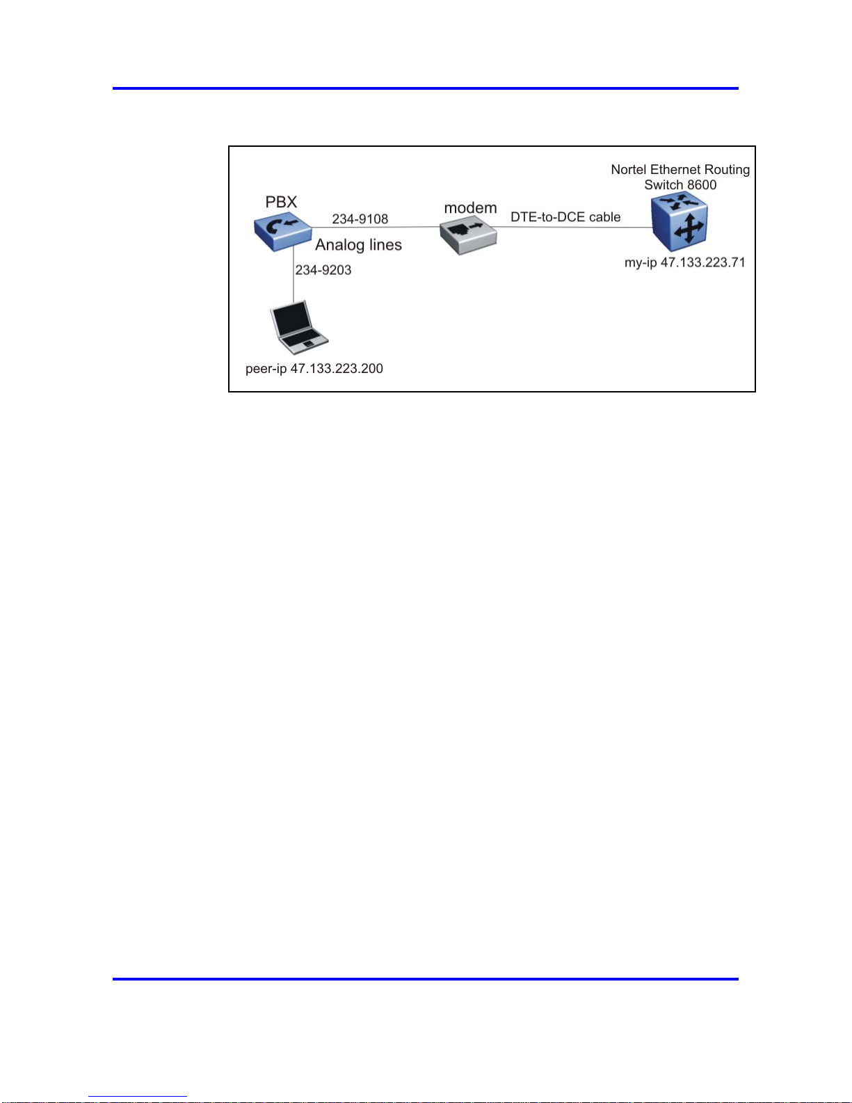
remote client PC and the switch. The following figure shows a standard
PPP connection to the Nortel Ethernet Routing Switch 8600.
Nortel Ethernet Routing Switch 8600
Commissioning
NN46205-319 01.01 Standard
30 May 2008
Copyright © 2008 Nortel Networks
.
Page 18
18 Commissioning fundamentals
Figure 1
PPP configuration topology
When you configure the modem port on the switch to use PPP, you must
also specify a PPP file. The PPP file is a text document which includes
all additional PPP configuration parameters to include when the switch
reboots. Enter one configuration parameter on each line with any required
values.
You can configure the connection to use the Challenge-Handshake
Authentication Protocol (CHAP) or the Password Authentication Protocol
(PAP). Both protocols require a secrets file. The secrets file is a text
document which includes the list of all users authorized to use the modem
port. You must list one user on each line and include specific parameters.
The format for each user is client server password IP address. The
following list explains each option.
• client: the name of the user. This value is the logon name of the
authorized user. This value should be the name or ID of the user,
similar to a Windows or UNIX logon.
• server: the name of the remote device, which is often the dial-in server.
Use an asterisk (*) to indicate any server name is acceptable.
• password: the password for the user.
• IP address: the IP address associated with the user.
The value for the IP address depends on the desired configuration of the
modem. If all users must use the same IP address, you must specify
the same IP address for all users in the file and it must be the same IP
address that you configure as the peer-ip for the modem port. Configure
the IP settings on the client to obtain an IP address automatically.
Nortel Ethernet Routing Switch 8600
Commissioning
NN46205-319 01.01 Standard
30 May 2008
Copyright © 2008 Nortel Networks
.
Page 19

System logon 19
If each user must use a different IP address, list each user with a different
IP address in the file. Configure the client IP settings to use a static IP
address that matches what you configure in the secrets file.
An example secrets file looks like the following:
long * long 47.133.223.200
william * william 47.133.223.200
System logon
After the switch boot sequence is complete, a Login prompt appears. The
following table shows the default values for logon and password for the
console and Telnet sessions.
Table 2
Access levels and default logon values
Access level Description
Default
logon
Default
password
Read-only Permits view-only configuration and
status information. Is equivalent
to Simple Network Management
Protocol (SNMP) read-only
community access.
ro ro
Layer 1 read/write View most switch configuration
and status information and change
physical port settings.
l1 l1
Layer 2 read/write View and change configuration
and status information for Layer 2
(bridging and switching) functions.
l2 l2
Layer 3 read/write
(8600 switches only)
View and change configuration and
status information for Layer 2 and
Layer 3 (routing) functions.
l3 l3
Read/write View and change configuration and
status information across the switch.
You cannot change security and
password settings. This access level
is equivalent to SNMP read/write
community access.
rw rw
Read/write/all Permits all the rights of Read/Write
access and the ability to change
security settings, including the CLI
and Web-based management user
names and passwords and the SNMP
community strings.
rwa rwa
Nortel Ethernet Routing Switch 8600
Commissioning
NN46205-319 01.01 Standard
30 May 2008
Copyright © 2008 Nortel Networks
.
Page 20

20 Commissioning fundamentals
hsecure mode
The Nortel Ethernet Routing Switch 8600 supports a flag called high
secure (hsecure). hsecure introduces the following behaviors for the
password: 10-character enforcement, aging time, limitation of failed logon
attempts, and a protection mechanism to filter certain IP addresses.
After you enable the hsecure flag, the software enforces the 10-character
rule for all passwords. After you upgrade from a previous release, if the
password does not contain at least 10 characters, you must change your
password to the mandatory character length. This password must contain
a minimum of two uppercase characters, two lowercase characters, two
numbers, and two special characters.
Default passwords and community strings
If the switch boots in hsecure mode as a default factory setting, and you
have not configured a password, the default passwords are changed to
respect this rule. The following table describes the default passwords.
Table 3
Default setting passwords
User ID Default password
rwa rwarwarrwar
rw rwrwrwrwrw
ro rororororo
l3 l3l3l3l3l3
l2 l2l2l2l2l2
l1 l1l1l1l1l1
l4admin l4adminl4a
slbadmin slbadminsl
oper operoperop
l4oper l4operl4op
slboper slboperslb
ssladmin ssladminss
The following table describes the default community strings.
Table 4
Default community strings
User ID New community string
ro publiconly
l1
privateonly
l2
privateonly
Nortel Ethernet Routing Switch 8600
Commissioning
NN46205-319 01.01 Standard
30 May 2008
Copyright © 2008 Nortel Networks
.
Page 21

Setup utility 21
Table 4
Default community strings (cont’d.)
User ID New community string
l3
privateonly
rw privateonly
rwa secretonly
Aging enforcement
When you enable the hsecure flag, you can configure a duration after
which you must change your password. You configure the duration by
using the aging parameter.
For SNMP and FTP, after a password expires, access is denied. Before
you access the system, you must change a community string to a new
string consisting of more than eight characters.
Consider the following after you enable the hsecure flag:
• You cannot enable the Web server.
•
You cannot enable the SSH password authentication.
Filtering mechanism
Beginning with Release 4.1, incorrect IP source addresses as network
or broadcast addresses are filtered at the virtual router interface. For
example, V1 has the network address 192.168.168.0/24.
This change is valid for all IP subnets, not only for /24 as mentioned in
the example. Source addresses 192.168.168.0 and 192.168.168.255 are
discarded.
You can filter addresses only if you enable the hsecure mode.
Setup utility
To optimize the function of the Nortel Ethernet Routing Switch 8600, you
can obtain a list of hardware modules. Because the latest modules provide
advanced features, they work in certain operation modes that previous
modules do not support. The setup utility monitors system requirements
and obtains the highest system performance.
Use the setup utility to configure your switch by responding to a series of
on-screen questions. The setup utility saves the information in the boot
and run-time configuration files. The saved information and files ensure
Nortel Ethernet Routing Switch 8600
Commissioning
NN46205-319 01.01 Standard
30 May 2008
Copyright © 2008 Nortel Networks
.
Page 22

22 Commissioning fundamentals
the switch reboots in the desired operating mode. The setup utility also
provides error and warning messages to advise you of the ramifications of
certain hardware and software configurations.
For information about the supported operating modes, see Nortel Ethernet
Routing Switch 8600 Administration, NN46205-605.
The setup utility prompts you through the configuration process by asking
a series of questions. Answer each question or accept the default by
pressing Enter. Each question shows the default in brackets ([ ]) and the
acceptable parameter options in parenthesis.
After you run the setup utility, reboot the switch.
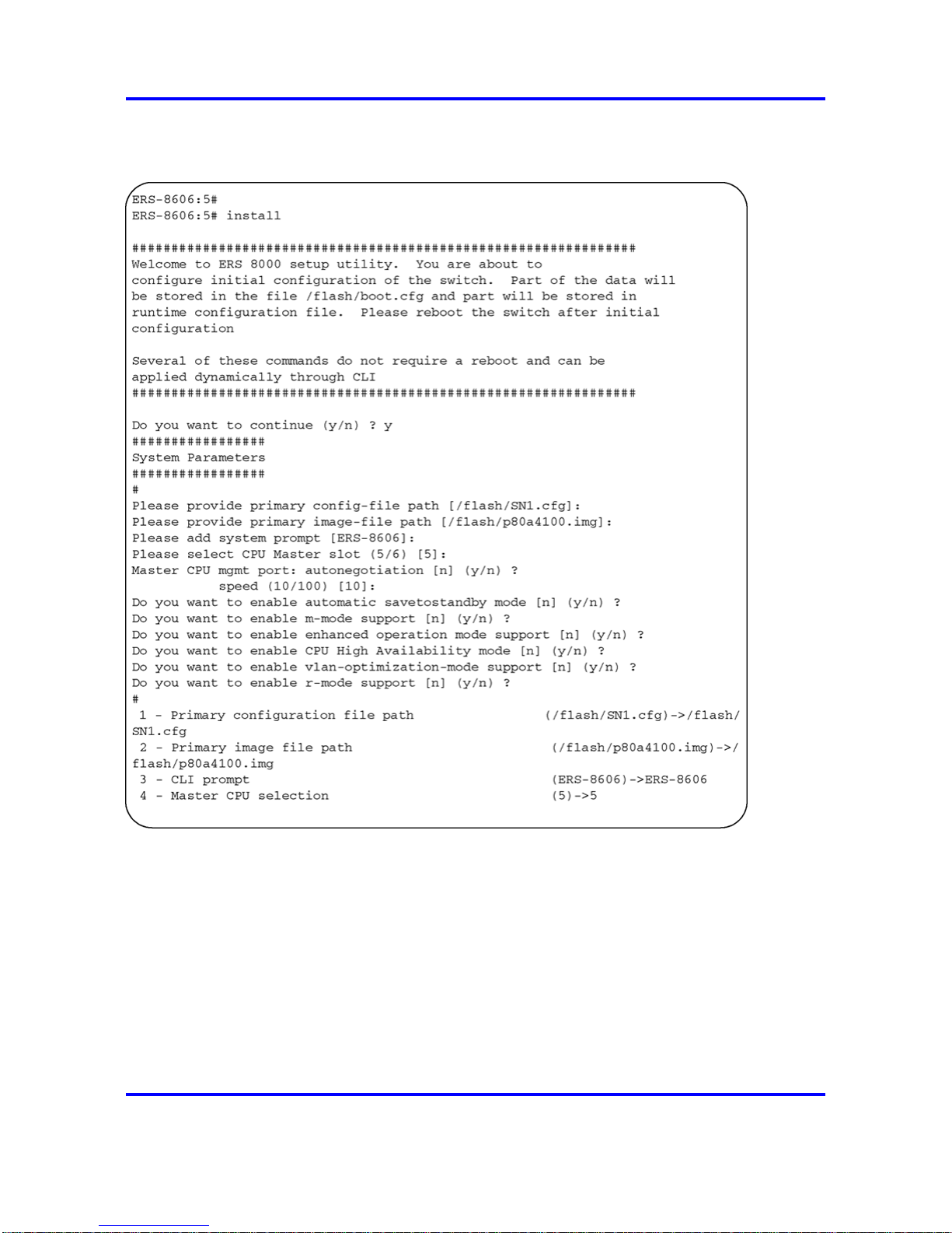
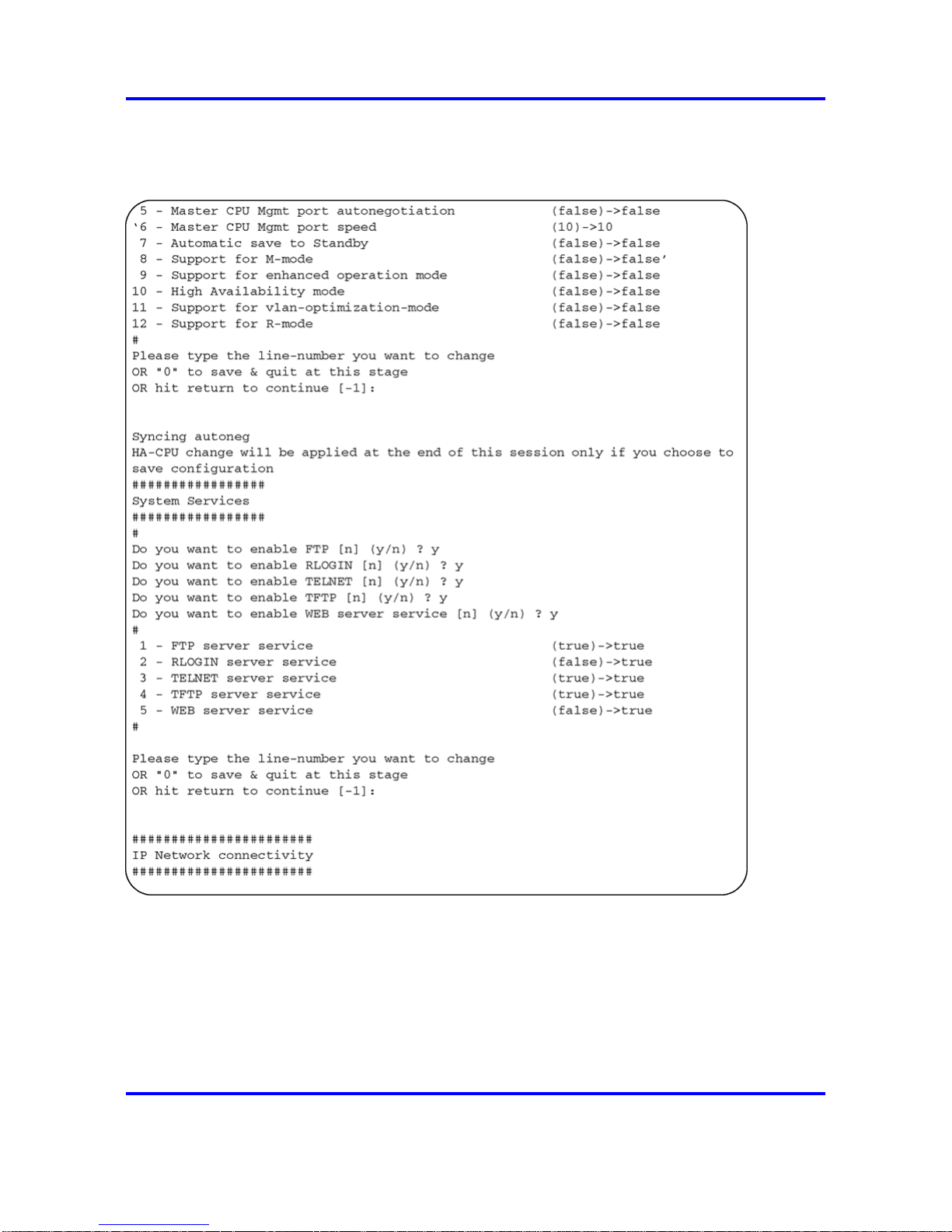
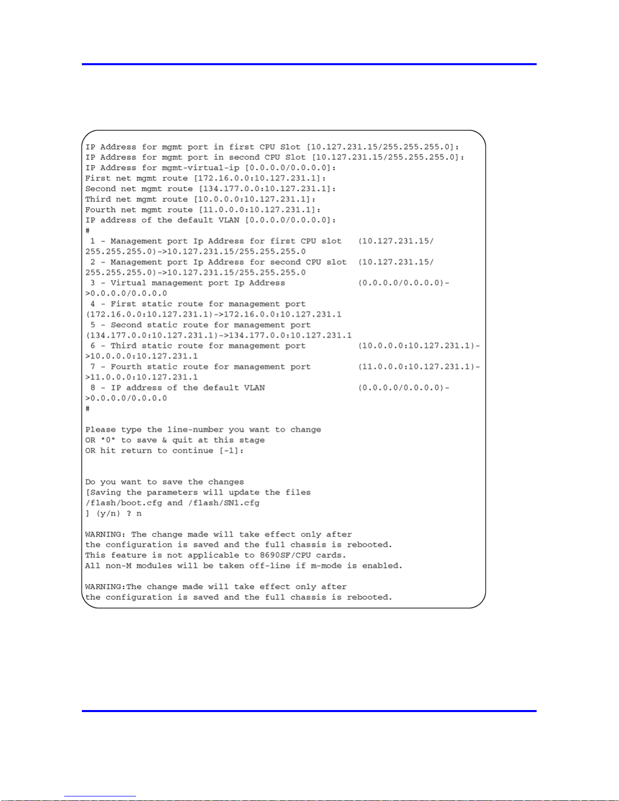
The following figures show sample output from the setup utility. This
example uses the default values.
Nortel Ethernet Routing Switch 8600
Commissioning
NN46205-319 01.01 Standard
30 May 2008
Copyright © 2008 Nortel Networks
.
Page 23
Setup utility 23
Figure 2
Setup utility example one
Nortel Ethernet Routing Switch 8600
Commissioning
NN46205-319 01.01 Standard
30 May 2008
Copyright © 2008 Nortel Networks
.
Page 24
24 Commissioning fundamentals
Figure 3
Setup utility example two
Nortel Ethernet Routing Switch 8600
Commissioning
NN46205-319 01.01 Standard
30 May 2008
Copyright © 2008 Nortel Networks
.
Page 25
Secure and nonsecure protocols 25
Figure 4
Setup utility example three
Secure and nonsecure protocols
The following table describes the secure and nonsecure protocols the
Nortel Ethernet Routing Switch 8600 supports.
Nortel Ethernet Routing Switch 8600
Commissioning
NN46205-319 01.01 Standard
30 May 2008
Copyright © 2008 Nortel Networks
.
Page 26

26 Commissioning fundamentals
Table 5
Secure and nonsecure protocols for IPv4
Nonsecure protocols
Default
status
Equivalent secure protocols
Default
status
FTP and TFTP Disabled SCP Disabled
Telnet Disabled
Secure SHell (SSH) v1, v2
Nortel recommends that you use
SSHv2 instead of SSHv1.
Disabled
SNMPv1, SNMPv2 Enabled
SNMPv3
You must load the DES/AES image on
the switch to use SNMPv3.
Enabled
Rlogin Disabled Secure SHell (SSH) v1, v2 Disabled
HTTP Disabled
No equivalent
ATTENTION
Nortel recommends that you do not
use this protocol due to the risk to
the security of your network.
Password encryption
Beginning in Release 4.1, the switch stores passwords in encrypted format
and no longer in the configuration file.
ATTENTION
If you load a configuration file saved prior to Release 3.7.6, saved passwords
from the configuration file are not recognized. If you boot the switch for the first
time with the software Release 3.7.6 or higher image, the switch resets the
password to default values and generates a log, which indicates the changes.
For security reasons, Nortel recommends that you configure the passwords to
values other than the factory defaults.
Management port
You must assign an IP address to the management port before you can
use it for out-of-band (OOB) management. In a switch with redundant
8691or 8692 modules, each management port uses a specific IP address.
In addition, you can create a virtual management port with an IP address
available to the master management module.
The master management module replies to all management requests
sent to the virtual IP address, and to requests sent to the management
port IP address. If the master management module fails and the backup
management module takes over, the virtual management port IP address
continues to provide management access to the switch.
Nortel Ethernet Routing Switch 8600
Commissioning
NN46205-319 01.01 Standard
30 May 2008
Copyright © 2008 Nortel Networks
.
Page 27

Management port 27
The following lists provides configuration considerations.
•
You can configure the standby IP to a subnet other than that of the
master IP using Device Manager only. Attempts to do so using CLI or
NNCLI will generate a warning message.
• If you use Device Manager, you can configure the standby IP to a
different subnet than the master IP, and you do not receive a warning
message.
Static IP entry for the OOB network management interface
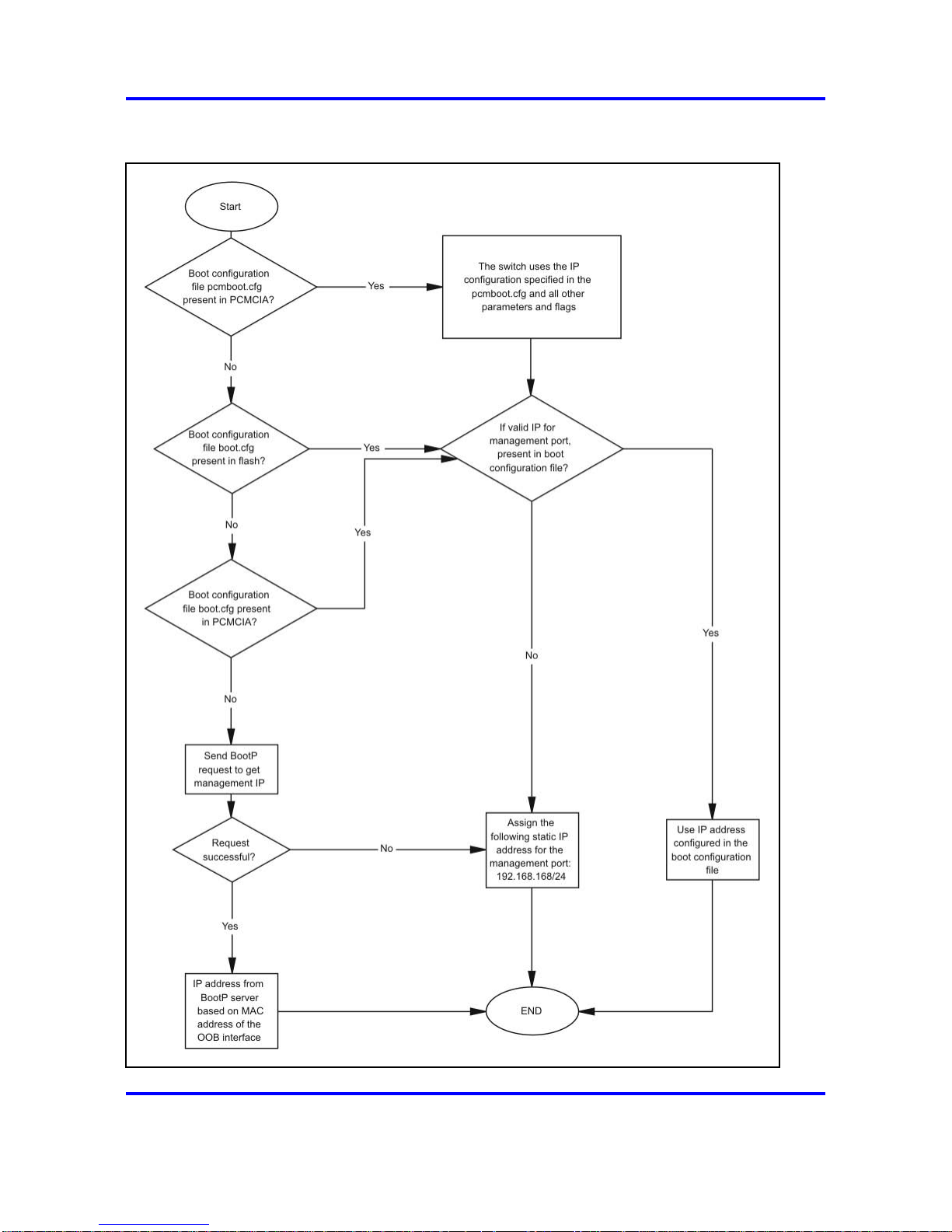
The following figure shows the OOB network management port default IP
assignment.
Nortel Ethernet Routing Switch 8600
Commissioning
NN46205-319 01.01 Standard
30 May 2008
Copyright © 2008 Nortel Networks
.
Page 28
28 Commissioning fundamentals
Figure 5
OOB network management port default IP flowchart
Nortel Ethernet Routing Switch 8600
Commissioning
NN46205-319 01.01 Standard
30 May 2008
Copyright © 2008 Nortel Networks
.
Page 29

Device Manager 29
The switch first checks for the file pcmboot.cfg, in Personal Computer
Memory Card International Association (PCMCIA). If not found, the switch
checks for the file boot.cfg in flash.
ATTENTION
If you use the boot configuration file from PCMCIA, you must rename the file to
pcmboot.cfg The boot.cfg file is no longer saved in PCMCIA. The file is saved
only in flash.
Web management
The Nortel Ethernet Routing Switch 8600 includes a Web management
interface you can use to monitor your switch through a Web browser from
anywhere on your network. The Web interface supports many of the same
monitoring features as the Device Manager software.
For information about configuration requirements and instructions to install
the help files, to enable the Web server using Device Manager, and to
access the Web interface, see Nortel Ethernet Routing Switch 8600 User
Interface Fundamentals, NN46205-308.
Device Manager
Device Manager is an SNMP-based graphical user interface (GUI) tool
designed to manage single devices. To use Device Manager, you must
connect to a management station running Device Manager in one of the
supported environments.
For information about Device Manager installation and startup, see
Nortel Ethernet Routing Switch 8600 User Interface Fundamentals,
NN46205-308.
Nortel Ethernet Routing Switch 8600
Commissioning
NN46205-319 01.01 Standard
30 May 2008
Copyright © 2008 Nortel Networks
.
Page 30

30 Commissioning fundamentals
Nortel Ethernet Routing Switch 8600
Commissioning
NN46205-319 01.01 Standard
30 May 2008
Copyright © 2008 Nortel Networks
.
Page 31

31
.
Commissioning
Commissioning follows hardware installation. The commissioning task
includes all the initial procedures you must use to bring the Ethernet
Routing Switch 8600 online and set up appropriate access for remote
users.
Commissioning tasks
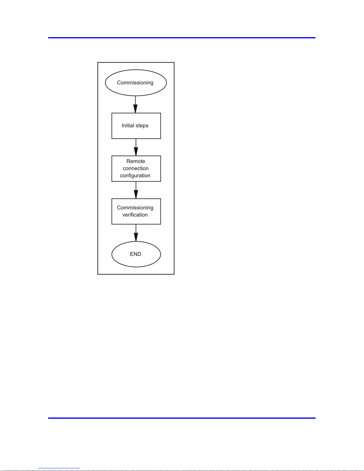
The following work flow shows the sequence of tasks you perform to
commission the Nortel Ethernet Routing Switch 8600. To link to a task, go
to “Commissioning navigation” (page 32).
Nortel Ethernet Routing Switch 8600
Commissioning
NN46205-319 01.01 Standard
30 May 2008
Copyright © 2008 Nortel Networks
.
Page 32
32 Commissioning
Figure 6
Commissioning tasks
Commissioning navigation
• “Initial steps using Device Manager” (page 33)
• “Initial steps using the CLI” (page 41)
• “Initial steps using the NNCLI” (page 69)
• “Remote connection configuration using Device Manager” (page 95)
•
“Remote connection configuration using the CLI” (page 103)
• “Remote connection configuration using the NNCLI” (page 113)
• “Commissioning verification” (page 123)
Nortel Ethernet Routing Switch 8600
Commissioning
NN46205-319 01.01 Standard
30 May 2008
Copyright © 2008 Nortel Networks
.
Page 33

33
.
Initial steps using Device Manager
The initial commissioning steps involve basic setting configuration.
Prerequisites to initial steps
•
You must install the hardware.
• You must install at least one cable to set up a remote connection to
the switch.
• You must power up the switch.
Initial commissioning procedures
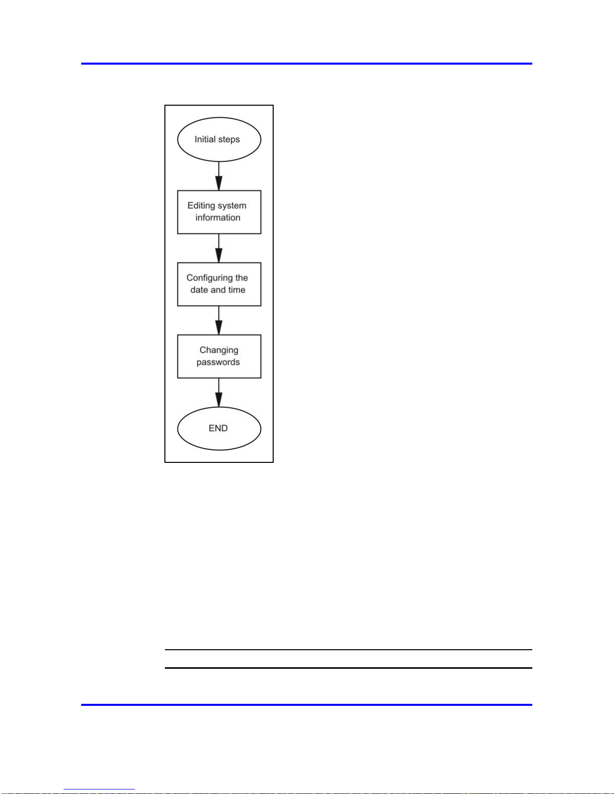
The following task flow shows the sequence of procedures you perform for
the initial commissioning steps. To link to a procedure, click the procedure
title in “Initial commissioning navigation” (page 34).
Nortel Ethernet Routing Switch 8600
Commissioning
NN46205-319 01.01 Standard
30 May 2008
Copyright © 2008 Nortel Networks
.
Page 34
34 Initial steps using Device Manager
Figure 7
Initial commissioning procedures
Initial commissioning navigation
• “Editing system information” (page 34)
• “Configuring the date and time” (page 37)
• “Changing passwords” (page 38)
Editing system information
You can edit system information, such as the contact person, the name of
the device, and the location.
Procedure steps
Step Action
1 On the Device Manager menu bar, choose Edit, Chassis.
Nortel Ethernet Routing Switch 8600
Commissioning
NN46205-319 01.01 Standard
30 May 2008
Copyright © 2008 Nortel Networks
.
Page 35

Editing system information 35
The Chassis dialog box appears with the System tab displayed.
2 Type the contact information.
3 Type the system name.
4 Type the location information.
5 Click Apply.
6 Click Close.
--End--
Variable definitions
Use the data in the following table to configure the System tab.
Variable Value
sysDescr Shows the system assigned name and the
software version
sysUpTime Shows the time since the system last
started
sysContact Configures the contact information (in this
case, an e-mail address) for the Nortel
support group
sysName Configures the name of this device
sysLocation Configures the physical location of this
device
VirtualIpAddr Configures the virtual IP address that is
advertised by the primary SF/CPU and
stored in the switch configuration file and
not the boot configuration file
VirtualNetMask Configures the net mask of the virtual
management IP address
VirtualIpv6Address Configures the virtual IPv6 address that
is advertised by the primary SF/CPU. and
stored in the switch configuration file and
not the boot configuration file
VirtualIPv6Prefix Length Configures the length of the virtual IPv6
prefix entry
DnsDomainName Configures the default domain for querying
the DNS server
LastChange Displays the time since the last
configuration change
Nortel Ethernet Routing Switch 8600
Commissioning
NN46205-319 01.01 Standard
30 May 2008
Copyright © 2008 Nortel Networks
.
Page 36

36 Initial steps using Device Manager
Variable Value
LastVlanChange Displays the time since the last VLAN
change
LastStatisticsReset Displays the time since the statistics
counters were last reset
LastRunTimeConfigSave Displays the last run-time configuration
saved
LastRunTimeConfigSaveToSlave Displays the last run-time configuration
saved to the standby device
LastBootConfigSave Displays the last boot configuration saved
LastBootConfigSaveOnSlave Displays the last boot configuration saved
on the standby device
DefaultRuntimeConfigFileName Displays the default Run-time configuration
file directory name
DefaultBootConfigFileName Displays the default boot configuration file
directory name
ConfigFileName Specifies the name of a new configuration
file
ActionGroup1
Can be one of the following actions:
•
resetCounters—resets all statistic
counters
• checkSwInFlash—checks the software
in flash
• saveRuntimeConfigToSlave—saves
the current run-time configuration to the
standby SF/CPU
•
saveToNVRAM—saves the current
run-time configuration to nonvolatile
RAM (NVRAM)
•
checkSwInPcmcia—checks the
software in PCMCIA
• saveBootConfig—saves the current
boot configuration
• saveToStandbyNVRAM—saves the
current run-time configuration to the
standby NVRAM
•
saveRuntimeConfig—saves the current
run-time configuration
Nortel Ethernet Routing Switch 8600
Commissioning
NN46205-319 01.01 Standard
30 May 2008
Copyright © 2008 Nortel Networks
.
Page 37

Configuring the date and time 37
Variable Value
•
saveSlaveBootConfig—saves the
current boot configuration to the
standby SF/CPU
•
loadLicense—loads a software license
file to enable features
ActionGroup2 Can be one of the following actions:
•
resetlstStatCounters—resets the IST
statistic counters
•
resetLspStats—resets the LSP
statistics
ActionGroup3
flushIpRouteTbl—flushes IP routes from
the routing table
ActionGroup4
Can be one of the following actions:
•
hardReset—resets the device and runs
power-on tests.
• softReset—resets the device without
running power-on tests
•
cpuSwitchOver—switch control from
one SF/CPU to another
• resetConsole—reinitializes the
hardware UART drivers. Use only if the
console or modem connection is hung
• resetModem—reinitializes the UART
drivers on the modem port. Use only
if the console or modem connection is
hung
Result Displays a message after you click Apply
Configuring the date and time
Use the User Set Time tab to configure the date and time.
Procedure steps
Step Action
1 In the Device Manager window, select the chassis.
2 From the Device Manager menu bar, choose Edit, Chassis.
The Chassis dialog box appears with the System tab displayed.
3 Click User Set Time.
Nortel Ethernet Routing Switch 8600
Commissioning
NN46205-319 01.01 Standard
30 May 2008
Copyright © 2008 Nortel Networks
.
Page 38

38 Initial steps using Device Manager
The User Set Time tab appears.
4 Type the correct details.
5 Click Apply.
--End--
Variable definitions
Use the data in the following table to configure the User Set Time tab.
Variable Value
Year Configures the year (integer 1998–2097)
Month Configures the month (integer 1–12)
Date Configures the day (integer 1–31)
Hour Configures the hour (integer 0–23)
Minute Configures the minute (integer 0–59)
Second Configures the second (integer 0–59)
Changing passwords
Configure new passwords for each access level, or change the logon or
password for the different access levels of the switch. After you receive
the Nortel Ethernet Routing Switch 8600, use default passwords to initially
access the CLI. If you use Simple Network Management Protocol version 3
(SNMPv3), you can change passwords that are in encrypted format.
Procedure steps
Step Action
1 From the Device Manager menu bar, choose Security, Control
Path, General.
The Control Path Security dialog box appears with the Port Lock
tab visible.
2 Click CLI.
The CLI tab appears.
3 Specify the username and password for the appropriate access
level.
4 Click Apply.
--End--
Nortel Ethernet Routing Switch 8600
Commissioning
NN46205-319 01.01 Standard
30 May 2008
Copyright © 2008 Nortel Networks
.
Page 39

Changing passwords 39
Variable definitions
Use the data in the following table to configure the CLI tab.
Variable Value
RWAUserName Specifies the user name for the read/write/all CLI
account.
RWAPassword Specifies the password for the read/write/all CLI
account.
RWEnable Activates the read/write access level.
RWUserName Specifies the user name for the read/write CLI
account.
RWPassword Specifies the password for the read/write CLI
account.
RWL3Enable Activates the read/write Layer 3 access level.
RWL3UserName Specifies the user name for the Layer 3 read/write
CLI account.
RWL3Password Specifies the password for the Layer 3 read/write CLI
account.
RWL2Enable Activates the read/write Layer 2 access level.
RWL2UserName Specifies the user name for the Layer 2 read/write
CLI account.
RWL2Password Specifies the password for the Layer 2 read/write CLI
account.
RWL1Enable Activates the read/write Layer 1 access level.
RWL1UserName Specifies the user name for the Layer 1 read/write
CLI account.
RWL1Password Specifies the password for the Layer 1 read/write CLI
account.
ROEnable Activates the read/only CLI account level.
ROUserName Specifies the user name for the read-only CLI
account.
ROPassword Specifies the password for the read-only CLI account.
MaxTelnetSessions Indicates the maximum number of concurrent Telnet
sessions (0–8).
MaxRloginSessions Indicates the maximum number of concurrent Rlogin
sessions(0–8).
Nortel Ethernet Routing Switch 8600
Commissioning
NN46205-319 01.01 Standard
30 May 2008
Copyright © 2008 Nortel Networks
.
Page 40

40 Initial steps using Device Manager
Variable Value
Timeout Indicates the number of seconds of inactivity for a
Telnet or Rlogin session before automatic timeout
and disconnect (30–65535 seconds).
NumAccessViolations Indicates the number of CLI access violations
detected by the system. This field is a read-only field.
Nortel Ethernet Routing Switch 8600
Commissioning
NN46205-319 01.01 Standard
30 May 2008
Copyright © 2008 Nortel Networks
.
Page 41

41
.
Initial steps using the CLI
The initial commissioning steps involve basic configuration settings.
Prerequisites to initial steps
•
You must install the hardware.
•
You must install at least one cable to set up a remote connection to
the switch.
• You must power up the switch.
Initial commissioning procedures
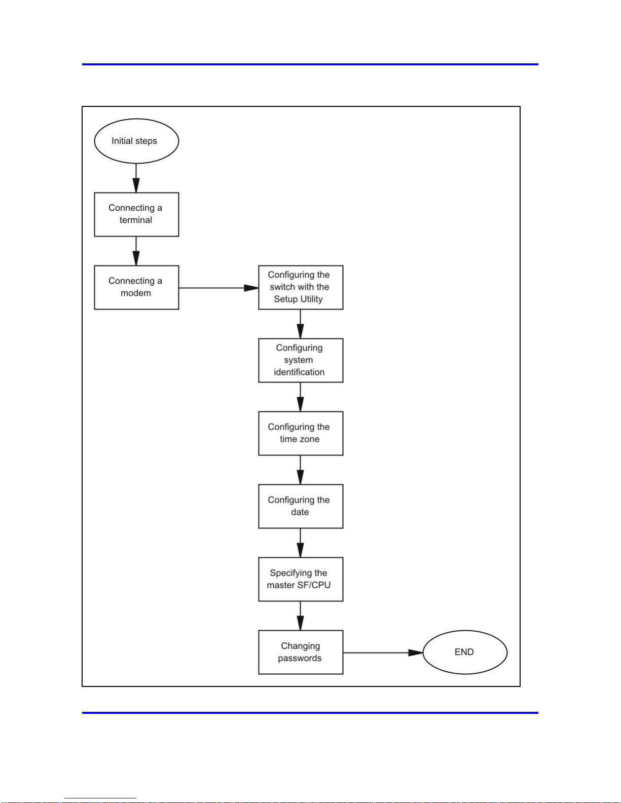
The following task flow shows the sequence of procedures you perform for
the initial commissioning steps. To link to a procedure, click the procedure
title in “Initial commissioning navigation” (page 43).
Nortel Ethernet Routing Switch 8600
Commissioning
NN46205-319 01.01 Standard
30 May 2008
Copyright © 2008 Nortel Networks
.
Page 42
42 Initial steps using the CLI
Figure 8
Initial commissioning procedures
Nortel Ethernet Routing Switch 8600
Commissioning
NN46205-319 01.01 Standard
30 May 2008
Copyright © 2008 Nortel Networks
.
Page 43

Job aid: Roadmap of initial CLI commands 43
Initial commissioning navigation
• “Job aid: Roadmap of initial CLI commands” (page 43)
• “Connecting a terminal” (page 45)
•
“Connecting a modem” (page 46)
• “Configuring the switch with the setup utility” (page 54)
• “Configuring system identification” (page 60)
• “Configuring the time zone” (page 62)
•
“Configuring the date” (page 63)
•
“Specifying the primary SF/CPU” (page 64)
• “Changing passwords” (page 64)
• “Resetting passwords” (page 68)
Job aid: Roadmap of initial CLI commands
The following table lists the commands and the parameters you use to
complete the procedures in this section.
Table 6
Job aid: Roadmap of initial CLI commands
Command
Parameter
config bootconfig master <cpu-slot>
8databits <true|false>
baud <rate>
enable <true|false>
mode <ascii|slip|ppp>
mtu <bytes>
my-ip <ipaddr>
peer-ip <ipaddr>
pppfile <file>
restart
slip-compression <true|false>
config bootconfig sio modem
slip-rx-compression <true|false>
Nortel Ethernet Routing Switch 8600
Commissioning
NN46205-319 01.01 Standard
30 May 2008
Copyright © 2008 Nortel Networks
.
Page 44

44 Initial steps using the CLI
Table 6
Job aid: Roadmap of initial CLI commands (cont’d.)
Command
Parameter
dst-end <Mm.n.d/hhmm|MMddhhmm>
dst-name <dstname>
dst-offset <minutes>
dst-start <Mm.n.d/hhmm|MMddhhmm>
info
name <tz>
config bootconfig tz
offset-from-utc <minutes>
access level <access level>
<enable|disable>
aging <days>
default-lockout-time <secs>
info
l1 <username> [ <password> ]
l2 <username> [ <password> ]
l3 <username> [ <password> ]
l4admin <username>
l4oper <username>
lockout-time <HostAddress> <secs>
min-passwd-len <integer>
oper <username>
password-history <number>
ro <username> [ <password> ]
rw <username> [ <password> ]
rwa <username> [ <password> ]
slboper <username>
slbadmin <username>
config cli password
ssladmin <username>
config setdate <MMddyyyyhhmmss>
Nortel Ethernet Routing Switch 8600
Commissioning
NN46205-319 01.01 Standard
30 May 2008
Copyright © 2008 Nortel Networks
.
Page 45

Connecting a terminal 45
Table 6
Job aid: Roadmap of initial CLI commands (cont’d.)
Command
Parameter
contact <contact>
clock-sync-time <minutes>
contact <contact>
ecn-compatibility <enable|disable>
force-topology-ip-flag <true|false>
global-filter <enable|disable>
info
location <location>
max-vlan-resource-reservation
<enable|disable>
mgmt-virtual-ip <ipaddr/mask>
mgmt-virtual-ipv6 <ipv6addr/prefix-
len>
mroute-stream-limit <enable|disable>
mtu <bytes>
multicast-resource-reservation
<value>
name <prompt>
portlock <on|off>
sendAuthenticationTrap <true|false>
smlt-on-single-cp <enable|disable>
[timer <value ]
topology <on|off>
udp-checksum <enable|disable>
udpsrc-by-vip <enable|disable>
vlan-bysrcmac <enable|disable>
config sys set
wsm-direct-mode <enable|disable>
install name <prompt>
reset-passwd name <prompt>
show bootconfig master
Connecting a terminal
Connect a terminal to the serial console interface to monitor and configure
the switch.
Nortel Ethernet Routing Switch 8600
Commissioning
NN46205-319 01.01 Standard
30 May 2008
Copyright © 2008 Nortel Networks
.
Page 46

46 Initial steps using the CLI
Prerequisites
• To use the console port, you need the following equipment:
—
A terminal or teletypewriter (TTY)-compatible terminal, or a portable
computer with a serial port and terminal-emulation software.
—
An Underwriters Laboratories (UL)-listed straight-through or null
modem RS-232 cable with a female DB-9 connector for the
console port on the switch. The other end of the cable must
use a connector appropriate to the serial port on your computer
or terminal. Most computers or terminals use a male DB-25
connector. You can find a null modem cable with the chassis.
• You must shield the cable connected to the console port to comply with
emissions regulations and requirements.
Procedure steps
Step Action
1 Configure the terminal protocol as follows:
•
9600 baud
•
8 data bits
•
1 stop bit
•
No parity
2 Connect the RS-232 cable to the console port.
3 Connect the other end of the RS-232 cable to the terminal or
computer serial port.
4 Turn on the terminal.
5 Log on to the CLI.
--End--
Connecting a modem
Connect a modem to a Nortel Ethernet Routing Switch 8600 to establish a
connection with the switch. You can configure the modem port first using
another type of connection, such as a terminal connection, to the CLI.
Nortel Ethernet Routing Switch 8600
Commissioning
NN46205-319 01.01 Standard
30 May 2008
Copyright © 2008 Nortel Networks
.
Page 47

Connecting a modem 47
Prerequisites
• You need a DTE-to-DCE cable (straight or transmit cable) to connect
the Nortel Ethernet Routing Switch 8600 to the modem.
•
You must configure your client dial-up settings to establish the
connection to the modem.
Procedure steps
Step Action
1 In the run-time CLI, configure the modem port by using the
following command:
config bootconfig sio modem
Now you can enter options for this command level without
retyping the first part of the command.
ATTENTION
Nortel recommends that before you configure the Serial Line Internet
Protocol (SLIP) or Point-to-Point Protocol (PPP), you familiarize
yourself with these protocols.
2 Configure port parameters based on the modem requirements by
using the following commands:
baud <rate>
8databits <true|false>
mode <ascii|slip|ppp>
For information about the configuration requirements of your
modem, see the documentation shipped with the modem.
3 If you configure the port mode to slip, use the following
commands to configure other SLIP parameters:
slip-compression <true|false>
slip-rx-compression <true|false>
4 If you configure the port mode to ppp, use the following
commands to configure other PPP parameters:
mtu <bytes>
my-ip <ipaddr>
peer-ip <ipaddr>
pppfile <file>
5 On the modem, turn off echo mode and return code messaging.
6 Connect the modem to the modem port.
Nortel Ethernet Routing Switch 8600
Commissioning
NN46205-319 01.01 Standard
30 May 2008
Copyright © 2008 Nortel Networks
.
Page 48

48 Initial steps using the CLI
7 Save the boot configuration.
8 Reboot the switch.
--End--
Variable definitions
Use the data in the following table to use the config bootconfig sio
command.
Variable Value
8databits <true|false>
Specifies either 8 (true) or 7 (false)
data bits for each byte for software to
interpret. The default is false.
baud <rate>
Configures the baud rate for the port.
The default is 9600.
enable <true|false>
Enables or disables the port. The
default is true.
info
Displays information about the
specified port.
mode <ascii|slip|ppp>
Configures the communication
mode for the serial port. The default
is American Standard Code for
Information Interchange (ASCII).
If you are configuring the modem
port, you can configure the
port to use the SLIP or the PPP
communication mode.
mtu <bytes>
Configures the size of the maximum
transmission unit for a PPP link
(0–2048). The default is zero.
my-ip <ipaddr>
Configures the IP address for the
server side, the Nortel Ethernet
Routing Switch 8600, of the
point-to-point link. The default is
0.0.0.0. Nortel recommends that you
use the current IP address for the
management port.
Nortel Ethernet Routing Switch 8600
Commissioning
NN46205-319 01.01 Standard
30 May 2008
Copyright © 2008 Nortel Networks
.
Page 49

Connecting a modem 49
Variable Value
peer-ip <ipaddr>
Configures the peer (PC) IP address
on the point-to-point link. The default
is 0.0.0.0. The switch assigns this
value to any PC that connects
through the modem port with
configured TCP/IP properties to
obtain an IP address automatically.
If the client uses a static IP address,
the Nortel Ethernet Routing Switch
8600 accepts this address. If you use
Password Authentication Protocol
(PAP) authentication, you must
ensure that the client uses the correct
IP address.
pppfile <file>
Specifies the PPP configuration file
you must use to provide details for
authentication and other options
the switch includes during the boot
process. If you configure the port
mode to PPP, you must specify a
PPP filename. For more information
about this file, see “Procedure job
aid: PPP file” (page 49).
The PPP file name is a string value
of no more than 64 characters.
Identify the file in the format
{a.b.c.d:|peer:|/pcmcia/|/flash/}<file>.
ATTENTION
Do not specify a PPP filename with
more than 64 characters.
restart
Shuts down and initializes the port.
slip-compression <true|false>
Enables or disables Transmission
Control Protocol over IP (TCP/IP)
header compression for SLIP mode.
The default is false.
slip-rx-compression
<true|false>
Enables or disables TCP/IP header
compression on the receive packet
for SLIP mode. The default is false.
Procedure job aid: PPP file
Create the PPP file with one option on each line; comment lines start with
a pound sign (#). The following table lists the available options.
Nortel Ethernet Routing Switch 8600
Commissioning
NN46205-319 01.01 Standard
30 May 2008
Copyright © 2008 Nortel Networks
.
Page 50

50 Initial steps using the CLI
Table 7
Job aid: PPP file options
Option
Description
asyncmap <value>
Configures the desired async map to
the value you specify.
chap_file <file>
Obtains Challenge-Handshake
Authentication Protocol (CHAP)
secrets from the specified file. You
require this option if either peer
requires CHAP authentication. If your
users must use the same IP address,
the PAP and CHAP secret files must
specify the same IP address for all
users and it must match the peer-ip
setting on the modem port.
chap_interval <value>
Configures the interval, in seconds, for
the CHAP rechallenge to the value you
specify.
chap_restart <value>
Configures the timeout, in seconds,
for CHAP negotiation to the value you
specify.
debug
Activates the PPP daemon debug
mode.
default_route
Adds a default route to the system
routing table, after successful Internet
Protocol Control Protocol (IPCP)
negotiation. Use the peer as the
gateway. After the PPP connection
ends, the system removes this entry.
driver_debug
Activates PPP driver debug mode.
escape_chars <value>
Configures the characters to escape
on transmission to the value you
specify.
ipcp_accept_local
Accepts what the remote peer uses as
the target local IP address, even if the
local IP address is specified.
ipcp_accept_remote
Accepts what the remote peer uses as
the IP address, even if you specify the
remote IP address.
ipcp_max_configure <value>
Configures the maximum number of
transmissions for IPCP configuration
requests to the value you specify.
Nortel Ethernet Routing Switch 8600
Commissioning
NN46205-319 01.01 Standard
30 May 2008
Copyright © 2008 Nortel Networks
.
Page 51

Connecting a modem 51
Table 7
Job aid: PPP file options (cont’d.)
Option
Description
ipcp_max_failure <value>
Configures the maximum number
of IPCP configuration negative
acknowledgements (NAK) to the value
you specify.
ipcp_max_terminate <value>
Configures the maximum number of
transmissions for IPCP termination
requests to the value you specify.
ipcp_restart <value>
Configures the timeout, in seconds,
for IPCP negotiation to the value you
specify.
lcp_echo_failure <value>
Configures the maximum consecutive
Link Control Protocol (LCP) echo
failures to the value you specify.
lcp_echo_interval <value>
Configures the interval, in seconds,
between LCP echo requests to the
value you specify.
lcp_max_configure <value>
Configures the maximum number of
transmissions for LCP configuration
requests to the value you specify.
lcp_max_failure <value>
Configures the maximum number of
LCP configuration NAKs to the value
you specify.
lcp_max_terminate <value>
Configures the maximum number of
transmissions for LCP termination
requests to the value you specify.
lcp_restart <value>
Configures the timeout in seconds for
the LCP negotiation to the value you
specify.
local_auth_name <name>
Configures the local name for
authentication to the specified name.
login
Uses the logon password database
for Password Authentication Protocol
(PAP) peer authentication.
max_challenge <value>
Configures the maximum number of
transmissions for CHAP challenge
requests to the value you specify.
mru <value>
Configures the maximum receive unit
(MRU) size for negotiation to the value
you specify.
Nortel Ethernet Routing Switch 8600
Commissioning
NN46205-319 01.01 Standard
30 May 2008
Copyright © 2008 Nortel Networks
.
Page 52

52 Initial steps using the CLI
Table 7
Job aid: PPP file options (cont’d.)
Option
Description
mtu <value>
Configures the maximum transmission
unit (MTU) size for negotiation to the
value you specify.
netmask <value>
Configures the netmask value for
negotiation to the value you specify.
no_acc
Disables address control compression.
no_all
Does not request or allow options.
no_asyncmap
Disables async map negotiation.
no_chap
Disallows CHAP authentication with
peer.
no_ip
Disables IP address negotiation in
IPCP.
no_mn
Disables magic number negotiation.
no_mru
Disables MRU negotiation.
no_pap
Disables PAP authentication with the
peer.
no_pc
Disables protocol field compression.
no_vj
Disables Van Jacobson (VJ)
compression. VJ compression
reduces the regular 40-byte TCP/IP
header to 3 or 8 bytes.
no_vjccomp
Disables VJ connection ID
compression.
pap_file <file>
Obtains PAP secrets from the
specified file. You require this
option if either peer requires PAP
authentication. If your users must use
the same IP address, the PAP and
CHAP secret files must specify the
same IP address for all users and it
must match the peer-ip setting on the
modem port.
pap_max_authreq <value>
Configures the maximum number of
transmissions for PAP authentication
requests to the value you specify.
pap_passwd <password>
Configures the password for PAP
authentication with the peer to the
specified password.
Nortel Ethernet Routing Switch 8600
Commissioning
NN46205-319 01.01 Standard
30 May 2008
Copyright © 2008 Nortel Networks
.
Page 53

Connecting a modem 53
Table 7
Job aid: PPP file options (cont’d.)
Option
Description
pap_restart <value>
Configures the timeout, in seconds,
for PAP negotiation to the value you
specify.
pap_user_name <name>
Configures the user name for PAP
authentication with the peer to the
specified name.
passive_mode
Configures passive mode. PPP waits
for the peer to connect after an initial
connection attempt.
proxy_arp
Adds an entry to the Address
Resolution Protocol (ARP) table
with the IP address of the peer and the
Ethernet address of the local system.
remote_auth_name <name>
Configures the remote name for
authentication to the specified name.
require_chap
Requires CHAP authentication with
peer.
require_pap
Requires PAP authentication with
peer.
silent_mode
Configures silent mode. PPP does
not transmit LCP packets to initiate a
connection until it receives a valid LCP
packet from the peer.
vj_max_slots <value>
Configures the maximum number of
VJ compression header slots to the
value you specify.
Table 8 "Sample PPP file" (page 53) shows example contents from a PPP
file.
Table 8
Sample PPP file
passive_mode
lcp_echo_interval 30
lcp_echo_failure 10
require_chap
require_pap
no_vj
ipcp_accept_remote
login
Nortel Ethernet Routing Switch 8600
Commissioning
NN46205-319 01.01 Standard
30 May 2008
Copyright © 2008 Nortel Networks
.
Page 54

54 Initial steps using the CLI
chap_file "my_chap"
pap_file "my_pap"
Configuring the switch with the setup utility
Configure the switch with the setup utility to monitor system requirements
and obtain the maximum system performance.
Procedure steps
Step Action
1 Start the setup utility by using the following command:
install
2 Respond to the series of questions displayed on the screen.
For more information about the prompted questions, see
“Procedure job aid: setup utility prompts” (page 54).
3 Reboot the switch.
--End--
Procedure job aid: setup utility prompts
The following table lists the questions prompted by the setup utility and
provides a description for each.
Table 9
Job aid: Setup utility prompt descriptions
Prompt Description and action
Please provide primary
config-file path
[/flash/config.cfg]:
Description: Indicates the name of the
primary configuration file.
Action: Press Enter to accept the default
(/flash/config.cfg), or type a different file name
for the primary configuration file. To store your
configuration file on the PCMCIA card, use
/PCMCIA/config.cfg. To specify the path to
the file is optional.
Nortel Ethernet Routing Switch 8600
Commissioning
NN46205-319 01.01 Standard
30 May 2008
Copyright © 2008 Nortel Networks
.
Page 55

Configuring the switch with the setup utility 55
Table 9
Job aid: Setup utility prompt descriptions (cont’d.)
Prompt Description and action
Please provide primary
image-file path
[/flash/p80a4100.img]:
Description: Indicates the name of the
primary image file.
Action: Press Enter to accept the default
(p80a4100.img), or type a different file name
for the primary image file. To specify the path
to the file is optional. If your run-time image
resides on your PCMCIA card, you must
specify the path as /PCMCIA/ filename.
Please add system prompt
[ERS-8606]:
Description: Specifies the text for the
prompt.
Action: Press Enter to accept the default
(ERS-8610), or type a different string of up to
20 characters.
Please select CPU primary slot
(5/6) [5]:
Description: Indicates the slot number of the
primary central processing unit (CPU). The
slot can be 5 or 6.
Action: Press Enter to accept the default (5),
or specify 6.
Primary CPU mgmt port:
autonegotiation [n] (y/n)?
Description: Specifies if you want the
primary CPU to use autonegotiation.
Action: Enter n to accept the default, or enter
y to indicate that you want the primary CPU
management port to use autonegotiation.
speed (10/100) [10]:
Description: Specifies the line speed in Mb/s.
Action: Press Enter to accept the default (10
Mb/s), or specify 100 Mb/s.
Do you want to enable
automatic savetostandby
mode [n] (y/n)?
Description: Specifies if you want the boot
and run-time configuration files to be saved on
the backup CPU.
Action: Enter y to save the boot and run-time
configuration files on the backup CPU. Accept
the default (n) to save boot and run-time
configuration files on the primary CPU.
Nortel Ethernet Routing Switch 8600
Commissioning
NN46205-319 01.01 Standard
30 May 2008
Copyright © 2008 Nortel Networks
.
Page 56

56 Initial steps using the CLI
Table 9
Job aid: Setup utility prompt descriptions (cont’d.)
Prompt Description and action
Do you want to enable m-mode
support [n] (y/n)?
Description: Specifies if you want the
chassis to run in 128 K mode. To run in 128 K
mode, the CPU module must be an 8691 or
higher and the switch must use at least one
8600 module (128 K module).
ATTENTION
If you enable M mode support and you
use a mixed configuration of modules, you
disable the E modules and Pre-E modules.
ATTENTION
If you enable M mode support and you
use a mixed configuration of modules, you
disable the E modules.
Action: Enter y if you want the chassis to run
in 128 K M mode. Accept the default (n), if
you want it to run in 32 K mode only.
Do you want to enable
enhanced operation mode
support [n] (y/n)?
Description: Specifies if you want to enable
enhanced operation mode. Enhanced
operation mode increases the maximum
number of VLANs when you use MultiLink
Trunking (MLT) (1980) and Split MLT (SMLT)
(989). This mode requires 8600 E- or
M-modules.
ATTENTION
If you enable enhanced operation mode and
you use a mixed configuration of modules,
you disable the Pre-E modules.
Action: Enter y to enable enhanced operation
mode. Accept the default (n), to not enable
enhanced operation mode.
Nortel Ethernet Routing Switch 8600
Commissioning
NN46205-319 01.01 Standard
30 May 2008
Copyright © 2008 Nortel Networks
.
Page 57

Configuring the switch with the setup utility 57
Table 9
Job aid: Setup utility prompt descriptions (cont’d.)
Prompt Description and action
Do you want to enable CPU
High Availability mode [n]
(y/n)?
Description: Specifies if you want to enable
CPU high availability (HA) mode. Use CPU
HA mode to recover switches with two CPUs
quickly from a failure of one of the CPUs. In
HA mode (hot standby), you synchronize and
configure the two CPUs in the same mode, so
they are compatible.
Action: Specify y to enable CPU high
availability (HA) mode. Accept the default (n),
to not enable CPU HA mode.
Do you want to enable
vlan-optimization-mode support
[n] (y/n) ?
Description: Specifies if you want to enable
support for the VLAN optimization mode.
Action: Specify y to enable VLAN
optimization mode support. Accept the
default (n) to not enable VLAN optimization
mode support.
Do you want to enable r-mode
support [n] (y/n) ?
Description: Specifies if you want to enable
support for the R mode support.
Action: Specify y to enable R mode support.
Accept the default (n) to not enable R mode
support.
Do you want to enable FTP [n]
(y/n)?
Description: Specifies if you want users to
access the switch by File transfer Protocol
(FTP).
Action: Enter y to enable FTP for remote
users. Accept the default (n) to not enable
FTP.
Do you want to enable
RLOGIN [n] (y/n)?
Description: Specifies if you want to access
the switch by Rlogin.
Action: Enter y to enable Rlogin for remote
users. Accept the default (n) to not enable
Rlogin.
Nortel Ethernet Routing Switch 8600
Commissioning
NN46205-319 01.01 Standard
30 May 2008
Copyright © 2008 Nortel Networks
.
Page 58

58 Initial steps using the CLI
Table 9
Job aid: Setup utility prompt descriptions (cont’d.)
Prompt Description and action
Do you want to enable
TELNET [n] (y/n)?
Description: Specifies if you want to access
the switch by Telnet.
Action: Enter y to enable Telnet. Accept the
default (n) to not enable Telnet.
Do you want to enable TFTP
[n] (y/n)?
Description: Specifies if you want to access
the switch by Trivial FTP (TFTP).
Action: Enter y to enable TFTP. Accept the
default (n) to not enable TFTP.
Do you want to enable WEB
server service [n] (y/n)?
Description: Specifies if you want to enable
Web server service. Use the Web server
service to monitor statistics for the switch with
your Web browser.
Action: Enter y to enable Web server
service. Accept the default (n) to not enable
Web server service.
IP Address for mgmt port in
first CPU Slot [192.168.168.16
8/255.255.2.55.0]:
Description: Indicates the IP address for the
management port in the CPU slot you specify.
Action: Type the IP address of the
management port in the first CPU slot.
IP Address for mgmt port in
second CPU Slot [192.168.168
.169/255.255.255.0]:
Description: Indicates the IP address for the
management port in the CPU slot you specify.
Action: Type the IP address of the
management port in the second CPU slot.
IP Address for mgmt-virtual-ip
[0.0.0.0/0.0.0.0]:
Description: Indicates the IP address for the
virtual management port.
Action: Type the IP address of the virtual
management port. Accept the default
(0.0.0.0/0.0.0.0) to not specify an IP address.
Nortel Ethernet Routing Switch 8600
Commissioning
NN46205-319 01.01 Standard
30 May 2008
Copyright © 2008 Nortel Networks
.
Page 59

Configuring the switch with the setup utility 59
Table 9
Job aid: Setup utility prompt descriptions (cont’d.)
Prompt Description and action
First net mgmt route
[0.0.0.0:0.0.0.0]:
Description: Specifies the IP address of
the first network management route (static
route from the network management port to a
device in the network).
Action: Type the network and gateway IP
address of the first network management
route.
Second net mgmt route
[0.0.0.0:0.0.0.0]:
Description: Specifies the IP address of the
second network management route.
Action: Type the IP address of the second
network management route (static route from
the network management port to a device in
the network).
Third net mgmt route
[0.0.0.0:0.0.0.0]:
Description: Specifies the IP address of the
third network management route.
Action: Type the IP address of the third
network management route (static route from
the network management port to a device in
the network).
Fourth net mgmt route
[0.0.0.0:0.0.0.0]:
Description: Specifies the IP address of the
fourth network management route.
Action: Type an IP address of the fourth
network management route (static route from
the network management port to a device in
the network).
IP address of the default VLAN
[0.0.0.0/0.0.0.0]:
Description: Specifies the IP address of the
default Virtual Local Area Network (VLAN).
Action: Type the IP address of the default
VLAN.
Do you want to save the
changes
[Saving the parameters
updates the files /flash/boot.cfg
and /flash/dvmrp_pol.cfg]
(y/n)?
Description: Saves your changes to the boot
and run-time configuration files.
Action: Enter y to save the boot and run-time
configuration files. Enter n if you do not want
to save your changes.
Nortel Ethernet Routing Switch 8600
Commissioning
NN46205-319 01.01 Standard
30 May 2008
Copyright © 2008 Nortel Networks
.
Page 60

60 Initial steps using the CLI
Configuring system identification
Configure system identification to specify the system name, contact
person, and location of the switch.
Procedure steps
Step Action
1 Specify the system name by using the following command:
config sys set name <prompt>
2 Specify the name of the contact person for the switch by using
the following command:
config sys set contact <contact>
3 Define the location for the system by using the following
command:
config sys set location <location>
--End--
Variable definitions
Use the data in the following table to use the config sys set command.
Variable Value
clipId-topology-ip <id>
Sets the topology IP from the
available CLIP.id is the circless IP
interface id in the range of 1 to 256.
clock-sync-time <minutes>
Configures the RTC-to-system clock
synchronization time. minutes is the
RTC-to-System clock synchronization
time in minutes in the range of 15 to
3600.
contact <contact>
Alters the system contact.contact is
the system contact. The string length
is in the range of 0 to 255.
ecn-compatibility <enable|dis
able>
Enables or disables ecn-compatibility
feature.
force-topology-ip-flag
<true|false>
Sets flag to force choice of
topology-IP. true|false Enables or
disables Force Topology IP Flag.
global-filter <enable|disable>
Enables global filter feature.
info
Shows current level parameter
settings and next level directories.
Nortel Ethernet Routing Switch 8600
Commissioning
NN46205-319 01.01 Standard
30 May 2008
Copyright © 2008 Nortel Networks
.
Page 61

Configuring system identification 61
Variable Value
location <location>
Changes the system location.
max-vlan-resource-reservation
<enable|disable>
Enables MAX-VLAN feature.
mgmt-virtual-ip <ipaddr/mask>
Configures mgmt virtual
IP.ipaddr/mask is the IP address
and network mask {a.b.c.d/x |
a.b.c.d/x.x.x.x | default}.
mgmt-virtual-ipv6 <ipv6addr/pr
efix-len>
Configures mgmt virtual
IPV6.ipv6addr/prefix-len
is the IPV6 address. The string
length ranges from 0 to 46.
mroute-stream-limit
<enable|disable>
Global mroute stream limit
configuration.enable|disable
enables or disables mroute stream
limit.
mtu <bytes>
Sets MTU (with CRC) to one of three
values: 1522, 1950 and 9600 bytes.
is the MTU value in the range of
1522 to 9600.
multicast-resource-reservatio
n <value>
Reserves MGIDs for IPMC
use.value is the number of MGIDs
reserved for IPMC use in the range
from 64 to 4083.
name <prompt>
Changes the system name. prompt
is the box or root level prompt . The
string length ranges from 0 to 255.
portlock <on|off>
Turns portlock on/off.
sendAuthenticationTrap
<true|false>
Sets authentication trap to true or
false.
smlt-on-single-cp <enable|disa
ble> [timer <value> ]
Enables SMLT on Single CP feature.
•
enable|disable Enables
or disable SMLT on single CP
feature.
• [timer <value> ] is the timer
value for SMLT on single CP
feature timer in the range of 1 to
3.
topology <on|off>
Turns topology on/off.
udp-checksum <enable|disable>
Enables or disables UDP Checksum
calculation.
Nortel Ethernet Routing Switch 8600
Commissioning
NN46205-319 01.01 Standard
30 May 2008
Copyright © 2008 Nortel Networks
.
Page 62

62 Initial steps using the CLI
Configuring the time zone
Set the time zone to specify the time zone for your location and configure
settings for Daylight Saving Time (DST).
Procedure steps
Step Action
1 Configure the time zone by using the following command:
config bootconfig tz
2 Save the changed configuration to the boot.cfg and pcmboot.cfg
files.
3 Reboot the switch.
--End--
Variable definitions
Use the data in the following table to use the config bootconfig tz
command.
Variable Value
dst-end
<Mm.n.d/hhmm|MMddhhmm>
Configures the ending date of DST. You
can specify the time in one of two ways:
• Mm.n.d/hhmm specifies an hour on
the nth occurrence of a weekday in a
month. For example, M10.5.0/0200
means the fifth occurrence of Sunday
in the tenth month (October) at 2:00
a.m.
•
MMddhhmm specifies a month, day,
hour, and minute. For example,
10310200 means October 31 at 2:00
a.m.
dst-name <dstname> Configures an abbreviated name for the
local daylight saving time zone. dstname
is the name. For example, PDT is Pacific
Daylight Time.
Nortel Ethernet Routing Switch 8600
Commissioning
NN46205-319 01.01 Standard
30 May 2008
Copyright © 2008 Nortel Networks
.
Page 63

Configuring the date 63
Variable Value
dst-offset <minutes> Configures the daylight saving adjustment
in minutes.
The default is 60 minutes.
dst-start <Mm.n.d/hhmm|MMd
dhhmm>
Configures the starting date of daylight
saving time.
•
Mm.n.d/hhmm specifies an hour on
the nth occurrence of a weekday in a
month. For example, M10.5.0/0200
means the fifth occurrence of Sunday
in the tenth month (October) at 2:00
a.m.
•
MMddhhmm specifies a month, day,
hour, and minute. For example,
10310200 means October 31 at 2:00
a.m.
info
Displays time zone information.
name <tz>
Configures an abbreviated name for the
local time zone name. tz is the name.
For example, PST is Pacific Standard
Time.
offset-from-utc <minutes>
Configures the time zone offset in
minutes to subtract from Universal
Coordinated Time (UTC), where positive
numbers mean west of Greenwich
and negative numbers mean east of
Greenwich.
Configuring the date
Configure the calendar time in the form of month, day, year, hour, minute,
and second.
Prerequisites
• You must log on with the rwa credentials to use the command in this
procedure.
Procedure steps
Nortel Ethernet Routing Switch 8600
Commissioning
NN46205-319 01.01 Standard
30 May 2008
Copyright © 2008 Nortel Networks
.
Page 64

64 Initial steps using the CLI
Action
Configure the date by using the following command:
config setdate <MMddyyyyhhmmss>
Specifying the primary SF/CPU
Specify the primary SF/CPU to determine which SF/CPU you use as
the primary after the switch performs a full power cycle only. When the
SF/CPU becomes the primary, the master LED for the SF/CPU is on.
Procedure steps
Step Action
1 View the current setting for the primary SF/CPU by using the
following command:
show bootconfig master
2 Specify the slot of the primary SF/CPU by using the following
command:
config bootconfig master <cpu-slot>
3 Save the configuration to the boot.cfg and pcmboot.cfg files.
4 Reboot the switch.
--End--
Variable definitions
Use the data in the following table to use the config bootconfig
master command.
Variable Value
<cpu-slot>
Specifies the slot number for the
primary SF/CPU. This variable can be
5 or 6. The default primary is slot 5.
Changing passwords
Configure new passwords for each access level, or change the logon or
password for the different access levels of the switch. After you receive
the Nortel Ethernet Routing Switch 8600, use default passwords to initially
access the CLI. If you use Simple Network Management Protocol version 3
(SNMPv3), you can change encrypted passwords.
Nortel Ethernet Routing Switch 8600
Commissioning
NN46205-319 01.01 Standard
30 May 2008
Copyright © 2008 Nortel Networks
.
Page 65

Changing passwords 65
Prerequisites
• You must use an account with read/write/all privileges to change
passwords. For security, the switch saves passwords to a hidden file.
The optional parameter password is the password associated with the
user name or logon name.
Procedure steps
Action
Change a password by using the following command:
config cli password
Variable definitions
Use the data in the following table to use the config cli password
command.
Variable Value
access-level <access level>
<enable|disable>
Permits or blocks this access
level.
•
access level is an integer
from 2–8.
• enable|disable enables or
disables the chosen level.
aging <days>
Configures the time limit for
passwords. daysis the age-out
time as an integer from 1–365.
default-lockout-time <secs>
Changes the default lockout time
after three invalid attempts. secs
is the lockout time in seconds
and is in the 60–6500 range. The
default is 60 seconds.
info
Shows the level parameter
settings and the next level
directories.
Nortel Ethernet Routing Switch 8600
Commissioning
NN46205-319 01.01 Standard
30 May 2008
Copyright © 2008 Nortel Networks
.
Page 66

66 Initial steps using the CLI
l1 <username> [ <password> ]
Changes the Layer 1 read/write
logon or password.
•
username is the logon name
• password is the password
associated with the logon
name.
l2 <username> <password>
Changes the Layer 2 read/write
logon or password.
•
username is the logon name.
l3 <username> [ <password> ]
Changes the Layer 3 read/write
logon and/or password (applies
only to the Nortel Ethernet
Routing Switch 8600).
•
username is the logon name.
• password is the password
associated with the logon
name.
l4admin <username>
Configures the Layer 4
administrator logon to connect
to the Web Switching Module
(WSM). For more information
about the WSM, see Nortel
Ethernet Routing Switch
8600 Web Switching Module
Fundamentals, NN46205-314.
l4oper <username>
Configures the Layer 4 operator
logon to connect to the WSM.
For more information about
the WSM, see Nortel Ethernet
Routing Switch 8600 Web
Switching Module Fundamentals,
NN46205-314.
lockout-time <HostAddress> <secs>
Configures the host lockout time.
• HostAddress is the host IP
address in the format a.b.c.d.
• secs is the lockout time limit
in seconds for passwords
lockout in the 60–65000
range. The default is 60
seconds.
Nortel Ethernet Routing Switch 8600
Commissioning
NN46205-319 01.01 Standard
30 May 2008
Copyright © 2008 Nortel Networks
.
Page 67

Changing passwords 67
min-passwd-len <integer>
Configures the minimum length
for passwords in high-secure
mode. integer is in a minimum
range of 10–20.
oper <username>
Configures the operator logon to
connect to the WSM. For more
information about the WSM, see
Nortel Ethernet Routing Switch
8600 Web Switching Module
Fundamentals, NN46205-314.
password-history <number>
Specifies the number of
previous passwords the switch
stores. You cannot reuse a
password that is stored in the
password history.number uses a
configurable range of 3–32 and
the default is 3.
ro <username> [ <password> ]
Changes the read-only logon or
password.
• username is the logon name.
• password is the password
associated with the logon
name.
rw <username> [ <password> ]
Changes the read/write logon or
password.
•
username is the logon name.
•
password is the password
associated with the logon
name.
rwa <username> [ <password> ]
Changes the read/write/all logon
or password.
• username is the logon name.
• password is the password
associated with the logon
name.
slboper <username>
Configures the server load
balancing (SLB) operator logon
to connect to the WSM. For more
information about the WSM, see
Nortel Ethernet Routing Switch
8600 Web Switching Module
Fundamentals, NN46205-314.
Nortel Ethernet Routing Switch 8600
Commissioning
NN46205-319 01.01 Standard
30 May 2008
Copyright © 2008 Nortel Networks
.
Page 68

68 Initial steps using the CLI
slbadmin <username>
Configures the SLB administrator
logon to connect to the WSM.
For more information about
the WSM, see Nortel Ethernet
Routing Switch 8600 Web
Switching Module Fundamentals,
NN46205-314.
ssladmin <username>
Configures the ssladmin logon
to connect to and configure
the secure sockets layer (SSL)
Acceleration Module (SAM).
Resetting passwords
Reset passwords to restore them to the factory default values.
Procedure steps
Action
From the boot monitor CLI, reset passwords by using the
following command:
reset-passwd
Nortel Ethernet Routing Switch 8600
Commissioning
NN46205-319 01.01 Standard
30 May 2008
Copyright © 2008 Nortel Networks
.
Page 69

69
.
Initial steps using the NNCLI
The initial commissioning steps involve basic setting configuration.
Prerequisites to initial steps
•
You must install the hardware.
•
You must install at least one cable to set up a remote connection to
the switch.
• You must power up the switch.
Initial commissioning procedures
The following task flow shows the sequence of procedures you perform
for the initial commissioning steps. To link to a procedure, click on the
procedure title in “Initial commissioning navigation” (page 71).
Nortel Ethernet Routing Switch 8600
Commissioning
NN46205-319 01.01 Standard
30 May 2008
Copyright © 2008 Nortel Networks
.
Page 70
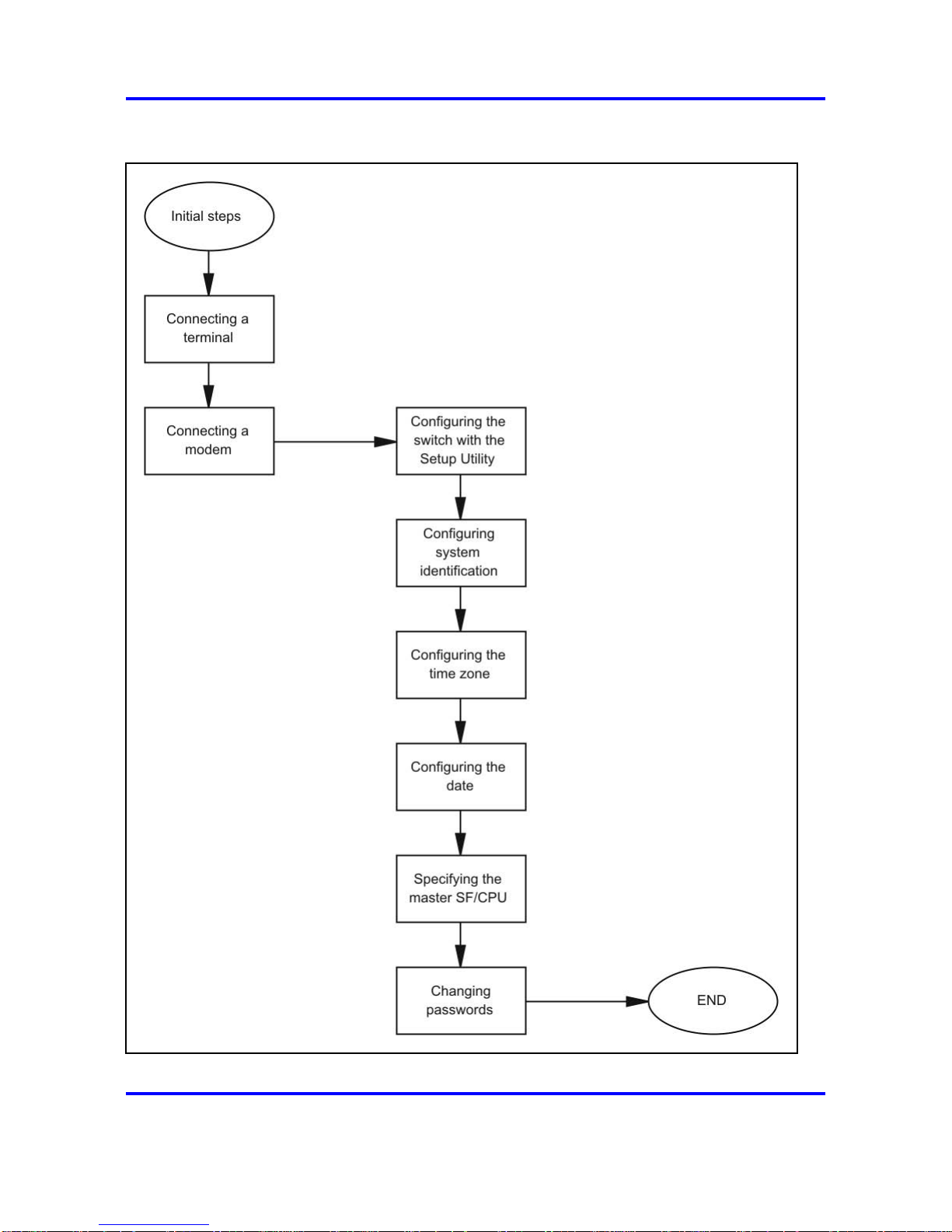
70 Initial steps using the NNCLI
Figure 9
Initial commissioning procedures
Nortel Ethernet Routing Switch 8600
Commissioning
NN46205-319 01.01 Standard
30 May 2008
Copyright © 2008 Nortel Networks
.
Page 71

Job aid: Roadmap of initial NNCLI commands 71
Initial commissioning navigation
• “Job aid: Roadmap of initial NNCLI commands” (page 71)
• “Connecting a terminal” (page 73)
•
“Connecting a modem” (page 74)
• “Configuring the switch with the setup utility” (page 81)
• “Configuring system identification” (page 87)
• “Configuring the time zone” (page 89)
•
“Configuring the date” (page 91)
•
“Specifying the primary SF/CPU” (page 91)
• “Changing passwords” (page 92)
Job aid: Roadmap of initial NNCLI commands
The following table lists the commands and the parameters you use to
complete the procedures in this section. The last two columns indicate
which commands support the no and default forms of the command.
Table 10
Job aid: Roadmap of initial NNCLI commands
Command
Parameter
Privileged EXEC mode
clock set
<MMddyyyyhhmmss>
install
show boot config master
Global Configuration mode
boot config master <cpu-slot>
Nortel Ethernet Routing Switch 8600
Commissioning
NN46205-319 01.01 Standard
30 May 2008
Copyright © 2008 Nortel Networks
.
Page 72

72 Initial steps using the NNCLI
Table 10
Job aid: Roadmap of initial NNCLI commands (cont’d.)
Command
Parameter
8databits
baud <rate>
mode <ascii|slip|ppp>
mtu <bytes>
my-ip <ipaddr>
peer-ip <ipaddr>
pppfile <file>
restart
slip-compression
boot config sio modem
slip-rx-compression
dst-end <Mm.n.d/hhmm|MMddhhmm>
dst-name <dstname>
dst-offset <minutes>
dst-start <Mm.n.d/hhmm|MMddhhmm>
name <tz>
boot config tz
offset-from-utc <minutes>
cli password <word> <access-level>
access-level <word>
aging-time day <1-365>
default-lockout-time
<60-65000>
lockout <word> time <time>
min-passwd-len <10-20>
password
password-history <3-32>
snmp-server contact <word>
agent-conformance enable
authentication-trap enable min-secure|semi
-secure|very-secure
Nortel Ethernet Routing Switch 8600
Commissioning
NN46205-319 01.01 Standard
30 May 2008
Copyright © 2008 Nortel Networks
.
Page 73

Connecting a terminal 73
Table 10
Job aid: Roadmap of initial NNCLI commands (cont’d.)
Command
Parameter
community
contact <WORD 0-255>
force
group
host
location <word>
log enable|maxfilesize
name <WORD 0-255>
notify-filter <WORD 1-32> <WORD 1-32>
sender-ip {A.B.C.D} {A.B.C.D}
user
view <WORD 1-32> <WORD 1-32>
sys name <word>
Connecting a terminal
Connect a terminal to the serial console interface to monitor and configure
the switch.
Prerequisites
• To use the console port, you need the following equipment:
— a terminal or teletypewriter (TTY)-compatible terminal, or a portable
computer with a serial port and terminal-emulation software
—
an Underwriters Laboratories (UL)-listed straight-through or null
modem RS-232 cable with a female DB-9 connector for the console
port on the switch
The other end of the cable must use a connector appropriate to
the serial port on your computer or terminal. Most computers or
terminals use a male DB-25 connector. You can find a null modem
cable with the chassis.
• You must shield the cable connected to the console port to comply with
emissions regulations and requirements.
Nortel Ethernet Routing Switch 8600
Commissioning
NN46205-319 01.01 Standard
30 May 2008
Copyright © 2008 Nortel Networks
.
Page 74

74 Initial steps using the NNCLI
Procedure steps
Step Action
1 Configure the terminal protocol as follows:
• 9600 baud
•
8 data bits
•
1 stop bit
•
No parity
2 Connect the RS-232 cable to the console port.
3 Connect the other end of the RS-232 cable to the terminal or
computer serial port.
4 Turn on the terminal.
5 Log on to the NNCLI.
--End--
Connecting a modem
Connect a modem to a Nortel Ethernet Routing Switch 8600 to establish a
connection with the switch. You can configure the modem port first using
another type of connection, such as a terminal connection, to the NNCLI.
Prerequisites
•
You need a DTE-to-DCE cable (straight or transmit cable) to connect
the Nortel Ethernet Routing Switch 8600 to the modem.
•
You must configure your client dial-up settings to establish the
connection to the modem.
•
You must log on to the Global Configuration mode in the NNCLI.
Procedure steps
Step Action
1 Configure port parameters based on the modem requirements by
using the following command:
boot config sio modem [8databits][baud <rate>] [mode
<ascii|slip|ppp>]
For information about the configuration requirements of your
modem, see the documentation shipped with the modem.
Nortel Ethernet Routing Switch 8600
Commissioning
NN46205-319 01.01 Standard
30 May 2008
Copyright © 2008 Nortel Networks
.
Page 75

Connecting a modem 75
ATTENTION
Nortel recommends that before you configure the Serial Line Internet
Protocol (SLIP) or the Point-to-Point Protocol (PPP), you familiarize
yourself with these protocols.
2 If you configure the port mode to slip, use the following
command to configure other SLIP parameters:
boot config sio modem [slip-compression] [slip-rx-comp
ression]
3 If you configure the port mode to ppp, use the following
commands to configure other PPP parameters:
boot config sio modem [mtu <bytes>] [my-ip <ipaddr>]
[peer-ip <ipaddr>] pppfile <file>
4 On the modem, turn off echo mode and return code messaging.
5 Connect the modem to the modem port.
6 Save the boot configuration.
7 Optionally, shutdown and reinitialize the port by using the
following command:
boot config sio modem restart
8 Reboot the switch.
--End--
Variable definitions
Use the data in the following table to use the boot config sio
command.
Variable Value
8databits
Specifies either 8 (enabled) or 7 (disabled)
data bits for each byte for software to interpret.
The default is disabled. Use the no operator
to remove this configuration. To configure this
option to the default value, use the default
operator with the command.
baud <rate>
Configures the baud rate for the port. The
default is 9600. To configure this option to the
default value, use the default operator with the
command.
Nortel Ethernet Routing Switch 8600
Commissioning
NN46205-319 01.01 Standard
30 May 2008
Copyright © 2008 Nortel Networks
.
Page 76

76 Initial steps using the NNCLI
Variable Value
mode <ascii|slip|ppp>
Configures the communication mode for the
serial port. The default is American Standard
Code for Information Interchange (ASCII).
If you are configuring the modem port, you can
configure the port to use either the SLIP or the
PPP communication mode.
To configure this option to the default value, use
the default operator with the command.
mtu <bytes>
Configures the size of the maximum transmission
unit for a PPP link (0–2048). The default is 0. To
configure this option to the default value, use the
default operator with the command.
my-ip <ipaddr>
Configures the IP address for the server side,
the Nortel Ethernet Routing Switch 8600, of
the point-to-point link. The default is 0.0.0.0.
Nortel recommends that you use the current IP
address for the management port. To configure
this option to the default value, use the default
operator with the command.
peer-ip <ipaddr>
Configures the peer (PC) IP address on the
point-to-point link. The default is 0.0.0.0. The
switch assigns this value to any PC that connects
through the modem port with configured TCP/IP
properties to obtain an IP address automatically.
If the client uses a static IP address, the Nortel
Ethernet Routing Switch 8600 accepts this
address. If you use Password Authentication
Protocol (PAP) authentication, you must ensure
that the client uses the correct IP address. To
configure this option to the default value, use the
default operator with the command.
pppfile <file>
Specifies the PPP configuration file to provide
details for authentication and other options to
include during the boot procedure of the switch.
The PPP filename is a string value of no more
than 64 characters. Identify the file in the format
{a.b.c.d:|peer:|/pcmcia/|/flash/}<file>. For more
information about this file, see “Procedure job
aid: PPP file” (page 77).
ATTENTION
Do not specify a PPP filename with more than
64 characters.
To configure this option to the default value, use
the default operator with the command.
Nortel Ethernet Routing Switch 8600
Commissioning
NN46205-319 01.01 Standard
30 May 2008
Copyright © 2008 Nortel Networks
.
Page 77

Connecting a modem 77
restart
Shuts down and initializes the port.
slip-compression
Enables or disables Transmission Control
Protocol over IP (TCP/IP) header compression
for SLIP mode. The default is false. Use the
no operator to remove this configuration. To
configure this option to the default value, use the
default operator with the command.
slip-rx-compression
Enables or disables TCP/IP header compression
on the receive packet for SLIP mode. The default
is false. Use the no operator to remove this
configuration. To configure this option to the
default value, use the default operator with the
command.
Procedure job aid: PPP file
Create the PPP file with one option on each line; comment lines start with
a pound sign (#). The following table lists the recognized options.
Table 11
Job aid: PPP file options
Option
Description
asyncmap <value>
Configures the desired async map to
the value you specify.
chap_file <file>
Obtains Challenge-Handshake
Authentication Protocol (CHAP)
secrets from the specified file. You
require this option if either peer
requires CHAP authentication. If your
users must use the same IP address,
the PAP and CHAP secret files must
specify the same IP address for all
users and it must match the peer-ip
setting on the modem port.
chap_interval <value>
Configures the interval, in seconds, for
the CHAP rechallenge to the value you
specify.
chap_restart <value>
Configures the timeout, in seconds,
for CHAP negotiation to the value you
specify.
debug
Activates the PPP daemon debug
mode.
Nortel Ethernet Routing Switch 8600
Commissioning
NN46205-319 01.01 Standard
30 May 2008
Copyright © 2008 Nortel Networks
.
Page 78

78 Initial steps using the NNCLI
Table 11
Job aid: PPP file options (cont’d.)
Option
Description
default_route
Adds a default route to the system
routing table, after successful Internet
Protocol Control Protocol (IPCP)
negotiation. Use the peer as the
gateway. After the PPP connection
ends, the system removes this entry.
driver_debug
Activates PPP driver debug mode.
escape_chars <value>
Configures the characters to escape
on transmission to the value you
specify.
ipcp_accept_local
Accepts what the remote peer uses as
the target local IP address, even if the
local IP address is specified.
ipcp_accept_remote
Accepts what the remote peer uses as
the IP address, even if you specify the
remote IP address.
ipcp_max_configure <value>
Configures the maximum number of
transmissions for IPCP configuration
requests to the value you specify.
ipcp_max_failure <value>
Configures the maximum number
of IPCP configuration negative
acknowledgements (NAK) to the value
you specify.
ipcp_max_terminate <value>
Configures the maximum number of
transmissions for IPCP termination
requests to the value you specify.
ipcp_restart <value>
Configures the timeout, in seconds,
for IPCP negotiation to the value you
specify.
lcp_echo_failure <value>
Configures the maximum consecutive
Link Control Protocol (LCP) echo
failures to the value you specify.
lcp_echo_interval <value>
Configures the interval, in seconds,
between LCP echo requests to the
value you specify.
lcp_max_configure <value>
Configures the maximum number of
transmissions for LCP configuration
requests to the value you specify.
lcp_max_failure <value>
Configures the maximum number of
LCP configuration NAKs to the value
you specify.
Nortel Ethernet Routing Switch 8600
Commissioning
NN46205-319 01.01 Standard
30 May 2008
Copyright © 2008 Nortel Networks
.
Page 79

Connecting a modem 79
Table 11
Job aid: PPP file options (cont’d.)
Option
Description
lcp_max_terminate <value>
Configures the maximum number of
transmissions for LCP termination
requests to the value you specify.
lcp_restart <value>
Configures the timeout in seconds for
the LCP negotiation to the value you
specify.
local_auth_name <name>
Configures the local name for
authentication to the specified name.
login
Uses the logon password database
for Password Authentication Protocol
(PAP) peer authentication.
max_challenge <value>
Configures the maximum number of
transmissions for CHAP challenge
requests to the value you specify.
mru <value>
Configures the maximum receive unit
(MRU) size for negotiation to the value
you specify.
mtu <value>
Configures the maximum transmission
unit (MTU) size for negotiation to the
value you specify.
netmask <value>
Configures the netmask value for
negotiation to the value you specify.
no_acc
Disables address control compression.
no_all
Does not request or allow options.
no_asyncmap
Disables async map negotiation.
no_chap
Disallows CHAP authentication with
peer.
no_ip
Disables IP address negotiation in
IPCP.
no_mn
Disables magic number negotiation.
no_mru
Disables MRU negotiation.
no_pap
Disables PAP authentication with the
peer.
no_pc
Disables protocol field compression.
no_vj
Disables Van Jacobson (VJ)
compression. VJ compression
reduces the regular 40-byte TCP/IP
header to 3 or 8 bytes.
Nortel Ethernet Routing Switch 8600
Commissioning
NN46205-319 01.01 Standard
30 May 2008
Copyright © 2008 Nortel Networks
.
Page 80

80 Initial steps using the NNCLI
Table 11
Job aid: PPP file options (cont’d.)
Option
Description
no_vjccomp
Disables VJ connection ID
compression.
pap_file <file>
Obtains PAP secrets from the
specified file. You require this
option if either peer requires PAP
authentication. If your users must use
the same IP address, the PAP and
CHAP secret files must specify the
same IP address for all users and it
must match the peer-ip setting on the
modem port.
pap_max_authreq <value>
Configures the maximum number of
transmissions for PAP authentication
requests to the value you specify.
pap_passwd <password>
Configures the password for PAP
authentication with the peer to the
specified password.
pap_restart <value>
Configures the timeout, in seconds,
for PAP negotiation to the value you
specify.
pap_user_name <name>
Configures the user name for PAP
authentication with the peer to the
specified name.
passive_mode
Configures passive mode. PPP waits
for the peer to connect after an initial
connection attempt.
proxy_arp
Adds an entry to the Address
Resolution Protocol (ARP) table
with the IP address of the peer and the
Ethernet address of the local system.
remote_auth_name <name>
Configures the remote name for
authentication to the specified name.
require_chap
Requires CHAP authentication with
peer.
require_pap
Requires PAP authentication with
peer.
Nortel Ethernet Routing Switch 8600
Commissioning
NN46205-319 01.01 Standard
30 May 2008
Copyright © 2008 Nortel Networks
.
Page 81

Configuring the switch with the setup utility 81
Table 11
Job aid: PPP file options (cont’d.)
Option
Description
silent_mode
Configures silent mode. PPP does
not transmit LCP packets to initiate a
connection until it receives a valid LCP
packet from the peer.
vj_max_slots <value>
Configures the maximum number of
VJ compression header slots to the
value you specify.
Table 12 "Sample PPP file" (page 81)shows example contents from a PPP
file.
Table 12
Sample PPP file
passive_mode
lcp_echo_interval 30
lcp_echo_failure 10
require_chap
require_pap
no_vj
ipcp_accept_remote
login
chap_file "my_chap"
pap_file "my_pap"
Configuring the switch with the setup utility
Configure the switch with the setup utility to monitor system requirements
and obtain the maximum system performance.
Prerequisites
• You must log on to the Privileged EXEC mode in the NNCLI.
Procedure steps
Step Action
1 Start the setup utility by using the following command:
install
2 Respond to the series of questions displayed on the screen.
Nortel Ethernet Routing Switch 8600
Commissioning
NN46205-319 01.01 Standard
30 May 2008
Copyright © 2008 Nortel Networks
.
Page 82

82 Initial steps using the NNCLI
For more information about the prompted questions, see
“Procedure job aid: setup utility prompts” (page 82).
3 Reboot the switch.
--End--
Procedure job aid: setup utility prompts
The following table lists the questions prompted by the setup utility and
provides a description for each.
Table 13
Job aid: Setup utility prompt descriptions
Prompt Description and action
Please provide primary
config-file path
[/flash/config.cfg]:
Description: Indicates the name of the
primary configuration file.
Action: Press Enter to accept the default
(/flash/config.cfg), or type a different file name
for the primary configuration file. To store your
configuration file on the PCMCIA card, use
/PCMCIA/config.cfg. To specify the path to
the file is optional.
Please provide primary
image-file path
[/flash/p80a4100.img]:
Description: Indicates the name of the
primary image file.
Action: Press Enter to accept the default
(p80a4100.img), or type a different file name
for the primary image file. To specify the path
to the file is optional. If your run-time image
resides on your PCMCIA card, you must
specify the path as /PCMCIA/ filename.
Please add system prompt
[ERS-8606]:
Description: Specifies the text for the
prompt.
Action: Press Enter to accept the default
(ERS-8610), or type a different string of up to
20 characters.
Please select CPU primary slot
(5/6) [5]:
Description: Indicates the slot number of the
primary central processing unit (CPU). The
slot can be 5 or 6.
Action: Press Enter to accept the default (5),
or specify 6.
Nortel Ethernet Routing Switch 8600
Commissioning
NN46205-319 01.01 Standard
30 May 2008
Copyright © 2008 Nortel Networks
.
Page 83

Configuring the switch with the setup utility 83
Table 13
Job aid: Setup utility prompt descriptions (cont’d.)
Prompt Description and action
Primary CPU mgmt port:
autonegotiation [n] (y/n)?
Description: Specifies if you want the
primary CPU to use autonegotiation.
Action: Enter n to accept the default, or enter
y to indicate that you want the primary CPU
management port to use autonegotiation.
speed (10/100) [10]:
Description: Specifies the line speed in Mb/s.
Action: Press Enter to accept the default (10
Mb/s), or specify 100 Mb/s.
Do you want to enable
automatic savetostandby
mode [n] (y/n)?
Description: Specifies if you want the boot
and run-time configuration files to be saved on
the backup CPU.
Action: Enter y to save the boot and run-time
configuration files on the backup CPU. Accept
the default (n) to save boot and run-time
configuration files on the primary CPU.
Do you want to enable m-mode
support [n] (y/n)?
Description: Specifies if you want the
chassis to run in 128 K mode. To run in 128 K
mode, the CPU module must be an 8691 or
higher and the switch must use at least one
8600 module (128 K module).
ATTENTION
If you enable M mode support and you
use a mixed configuration of modules, you
disable the E modules and Pre-E modules.
ATTENTION
If you enable M mode support and you
use a mixed configuration of modules, you
disable the E modules.
Action: Enter y if you want the chassis to run
in 128 K M mode. Accept the default (n), if
you want it to run in 32 K mode only.
Nortel Ethernet Routing Switch 8600
Commissioning
NN46205-319 01.01 Standard
30 May 2008
Copyright © 2008 Nortel Networks
.
Page 84

84 Initial steps using the NNCLI
Table 13
Job aid: Setup utility prompt descriptions (cont’d.)
Prompt Description and action
Do you want to enable
enhanced operation mode
support [n] (y/n)?
Description: Specifies if you want to enable
enhanced operation mode. Enhanced
operation mode increases the maximum
number of VLANs when you use MultiLink
Trunking (MLT) (1980) and Split MLT (SMLT)
(989). This mode requires 8600 E- or
M-modules.
ATTENTION
If you enable enhanced operation mode and
you use a mixed configuration of modules,
you disable the Pre-E modules.
Action: Enter y to enable enhanced operation
mode. Accept the default (n), to not enable
enhanced operation mode.
Do you want to enable CPU
High Availability mode [n]
(y/n)?
Description: Specifies if you want to enable
CPU high availability (HA) mode. Use CPU
HA mode to recover switches with two CPUs
quickly from a failure of one of the CPUs. In
HA mode (hot standby), you synchronize and
configure the two CPUs in the same mode, so
they are compatible.
Action: Specify y to enable CPU high
availability (HA) mode. Accept the default (n),
to not enable CPU HA mode.
Do you want to enable
vlan-optimization-mode support
[n] (y/n) ?
Description: Specifies if you want to enable
support for the VLAN optimization mode.
Action: Specify y to enable VLAN
optimization mode support. Accept the
default (n) to not enable VLAN optimization
mode support.
Do you want to enable r-mode
support [n] (y/n) ?
Description: Specifies if you want to enable
support for the R mode support.
Action: Specify y to enable R mode support.
Accept the default (n) to not enable R mode
support.
Nortel Ethernet Routing Switch 8600
Commissioning
NN46205-319 01.01 Standard
30 May 2008
Copyright © 2008 Nortel Networks
.
Page 85

Configuring the switch with the setup utility 85
Table 13
Job aid: Setup utility prompt descriptions (cont’d.)
Prompt Description and action
Do you want to enable FTP [n]
(y/n)?
Description: Specifies if you want users to
access the switch by File transfer Protocol
(FTP).
Action: Enter y to enable FTP for remote
users. Accept the default (n) to not enable
FTP.
Do you want to enable
RLOGIN [n] (y/n)?
Description: Specifies if you want to access
the switch by Rlogin.
Action: Enter y to enable Rlogin for remote
users. Accept the default (n) to not enable
Rlogin.
Do you want to enable
TELNET [n] (y/n)?
Description: Specifies if you want to access
the switch by Telnet.
Action: Enter y to enable Telnet. Accept the
default (n) to not enable Telnet.
Do you want to enable TFTP
[n] (y/n)?
Description: Specifies if you want to access
the switch by Trivial FTP (TFTP).
Action: Enter y to enable TFTP. Accept the
default (n) to not enable TFTP.
Do you want to enable WEB
server service [n] (y/n)?
Description: Specifies if you want to enable
Web server service. Use the Web server
service to monitor statistics for the switch with
your Web browser.
Action: Enter y to enable Web server
service. Accept the default (n) to not enable
Web server service.
IP Address for mgmt port in
first CPU Slot [192.168.168.16
8/255.255.2.55.0]:
Description: Indicates the IP address for the
management port in the CPU slot you specify.
Action: Type the IP address of the
management port in the first CPU slot.
IP Address for mgmt port in
second CPU Slot [192.168.168
.169/255.255.255.0]:
Description: Indicates the IP address for the
management port in the CPU slot you specify.
Action: Type the IP address of the
management port in the second CPU slot.
Nortel Ethernet Routing Switch 8600
Commissioning
NN46205-319 01.01 Standard
30 May 2008
Copyright © 2008 Nortel Networks
.
Page 86

86 Initial steps using the NNCLI
Table 13
Job aid: Setup utility prompt descriptions (cont’d.)
Prompt Description and action
IP Address for mgmt-virtual-ip
[0.0.0.0/0.0.0.0]:
Description: Indicates the IP address for the
virtual management port.
Action: Type the IP address of the virtual
management port. Accept the default
(0.0.0.0/0.0.0.0) to not specify an IP address.
First net mgmt route
[0.0.0.0:0.0.0.0]:
Description: Specifies the IP address of
the first network management route (static
route from the network management port to a
device in the network).
Action: Type the network and gateway IP
address of the first network management
route.
Second net mgmt route
[0.0.0.0:0.0.0.0]:
Description: Specifies the IP address of the
second network management route.
Action: Type the IP address of the second
network management route (static route from
the network management port to a device in
the network).
Third net mgmt route
[0.0.0.0:0.0.0.0]:
Description: Specifies the IP address of the
third network management route.
Action: Type the IP address of the third
network management route (static route from
the network management port to a device in
the network).
Fourth net mgmt route
[0.0.0.0:0.0.0.0]:
Description: Specifies the IP address of the
fourth network management route.
Action: Type an IP address of the fourth
network management route (static route from
the network management port to a device in
the network).
Nortel Ethernet Routing Switch 8600
Commissioning
NN46205-319 01.01 Standard
30 May 2008
Copyright © 2008 Nortel Networks
.
Page 87

Configuring system identification 87
Table 13
Job aid: Setup utility prompt descriptions (cont’d.)
Prompt Description and action
IP address of the default VLAN
[0.0.0.0/0.0.0.0]:
Description: Specifies the IP address of the
default Virtual Local Area Network (VLAN).
Action: Type the IP address of the default
VLAN.
Do you want to save the
changes
[Saving the parameters
updates the files /flash/boot.cfg
and /flash/dvmrp_pol.cfg]
(y/n)?
Description: Saves your changes to the boot
and run-time configuration files.
Action: Enter y to save the boot and run-time
configuration files. Enter n if you do not want
to save your changes.
Configuring system identification
Configure system identification to specify the system name, contact
person, and location of the switch.
Prerequisites
• You must log on to the Global Configuration mode in the NNCLI.
Procedure steps
Step Action
1 Change the system name by using the following command:
sys name <word>
2 Configure the system contact by using the following command:
snmp-server contact <word>
3 Configure the system location by using the following command:
snmp-server location <word>
--End--
Variable definitions
Use the data in the following table to use system-level commands.
Variable Value
agent-conformance
Enables agent conformance mode.
Nortel Ethernet Routing Switch 8600
Commissioning
NN46205-319 01.01 Standard
30 May 2008
Copyright © 2008 Nortel Networks
.
Page 88

88 Initial steps using the NNCLI
Variable Value
authentication-trap
Enables or disables generation of
authentication traps.
bootstrap
Sets SNMP initial user entry.
community
Sets community table.
contact <word>
Identifies the contact person who manages
the node. To include blank spaces in the
contact, use quotation marks (") around
the text. Use the no operator to remove
this configuration. To configure this option
to the default value, use the default
operator with the command. The default is
[email protected].
force-iphdr-sender
Sets same SNMP and IP sender flag.
force-trap-sender
Sets SNMP trap sender IP.
group
Sets SNMP v3 group access table.
host
Specifies hosts to receive SNMP
notifications.
location <word>
Identifies the physical location of the
node. To include blank spaces in the
location, use quotation marks (") around
the text. Use the no operator to remove
this configuration. To configure this option
to the default value, use the default
operator with the command. The default is
a Nortel address.
log
Specifies the SNMP log feature.
name <word>
Configures the system or root level
prompt name for the switch. word is an
ASCII string from 1 to 255 characters (for
example, LabSC7 or Closet4).
notify-filter
Creates new entry for notify filter table.
sender-ip
Sets SNMP trap sender IP.
user
Creates or modifies SNMPv3 user.
view
Creates or modifies an SNMP access
view.
Nortel Ethernet Routing Switch 8600
Commissioning
NN46205-319 01.01 Standard
30 May 2008
Copyright © 2008 Nortel Networks
.
Page 89

Configuring the time zone 89
Example of configuring system identification
Procedure steps
Step Action
1 Change the system name by using the following command:
ERS-8610:5(config)#sys name ERS-8610
2 Configure the system contact by using the following command:
ERS-8610:5(config)#snmp-server contact
[email protected]
3 Configure the system location by using the following command:
ERS-8610:5(config)#snmp-server location "12 Main
St, Vancouver, BC"
--End--
Configuring the time zone
Configure the time zone to specify the time zone for your location and
configure settings for Daylight Saving Time (DST).
Prerequisites
• You must log on to the Global Configuration mode in the NNCLI.
Procedure steps
Step Action
1 Configure the time zone by using the following command:
boot config tz
2 Save the changed configuration to the boot.cfg and pcmboot.cfg
files.
3 Reboot the switch.
--End--
Variable definitions
Use the data in the following table to use the boot config tz command.
Nortel Ethernet Routing Switch 8600
Commissioning
NN46205-319 01.01 Standard
30 May 2008
Copyright © 2008 Nortel Networks
.
Page 90

90 Initial steps using the NNCLI
Variable Value
dst-end <Mm.n.d/hhmm|MMddh
hmm>
Configures the ending date of DST. You
can specify the time in one of two ways:
•
Mm.n.d/hhmm specifies an hour on
the nth occurrence of a weekday in a
month. For example, M10.5.0/0200
means the fifth occurrence of Sunday
in the tenth month (October) at 2:00
a.m.
•
MMddhhmm specifies a month, day,
hour, and minute. For example,
10310200 means October 31 at 2:00
a.m.
dst-name <dstname> Configures an abbreviated name for the
local daylight saving time zone. dstname
is the name. For example, PDT is Pacific
Daylight Time.
To configure this option to the default
value, use the default operator with the
command.
dst-offset <minutes> Configures the daylight saving adjustment
in minutes.
The default is 60 minutes.
To configure this option to the default
value, use the default operator with the
command.
dst-start <Mm.n.d/hhmm|MMd
dhhmm>
Configures the starting date of DST.
•
Mm.n.d/hhmm specifies an hour on
the nth occurrence of a weekday in a
month. For example, M10.5.0/0200
means the fifth occurrence of Sunday
in the tenth month (October) at 2:00
a.m.
• MMddhhmm specifies a month, day,
hour, and minute. For example,
10310200 means October 31 at 2:00
a.m.
Nortel Ethernet Routing Switch 8600
Commissioning
NN46205-319 01.01 Standard
30 May 2008
Copyright © 2008 Nortel Networks
.
Page 91

Specifying the primary SF/CPU 91
Variable Value
name <tz>
Configures an abbreviated name for the
local time zone name. tz is the name.
For example, PST is Pacific Standard
Time.
To configure this option to the default
value, use the default operator with the
command.
offset-from-utc <minutes>
Configures the time zone offset in
minutes to subtract from Universal
Coordinated Time (UTC), where positive
numbers mean west of Greenwich
and negative numbers mean east of
Greenwich. To configure this option to the
default value, use the default operator
with the command.
Configuring the date
Configure the calendar time in the form of month, day, year, hour, minute,
and second.
Prerequisites
• You must log on to the Privileged EXEC mode in the NNCLI.
Procedure steps
Action
Configure the date by using the following command:
clock set <MMddyyyyhhmmss>
Specifying the primary SF/CPU
Specify the primary SF/CPU to determine which SF/CPU you use as
the master after the switch performs a full power cycle only. When the
SF/CPU becomes the primary, the master LED for the SF/CPU is on.
Prerequisites
• You must log on to at least Privileged EXEC mode to use the show
command.
• You must log on to the Global Configuration mode in the NNCLI to use
the configuration command in this procedure.
Nortel Ethernet Routing Switch 8600
Commissioning
NN46205-319 01.01 Standard
30 May 2008
Copyright © 2008 Nortel Networks
.
Page 92

92 Initial steps using the NNCLI
Procedure steps
Step Action
1 View the current setting for the primary SF/CPU by using the
following command:
show boot config master
2 Specify the slot of the primary SF/CPU by using the following
command:
boot config master <cpu-slot>
3 Save the configuration to the boot.cfg and pcmboot.cfg files.
4 Reboot the switch.
--End--
Variable definitions
Use the data in the following table to use the boot config master
command.
Variable Value
<cpu-slot>
Specifies the slot number for the
primary SF/CPU. This variable can be
5 or 6. The default primary is slot 5.
Changing passwords
Configure new passwords for each access level, or change the logon or
password for the different access levels of the switch. After you receive
the Nortel Ethernet Routing Switch 8600, use default passwords to initially
access the NNCLI. If you use Simple Network Management Protocol
version 3 (SNMPv3), you can change encrypted passwords.
Prerequisites
• You must use an account with read/write/all privileges to change
passwords. For security, the switch saves passwords to a hidden file.
• You must log on to the Global Configuration mode in the NNCLI.
Procedure steps
Step Action
1 Change a password by using the following command:
cli password <word> <access-level>
Nortel Ethernet Routing Switch 8600
Commissioning
NN46205-319 01.01 Standard
30 May 2008
Copyright © 2008 Nortel Networks
.
Page 93

Changing passwords 93
2 Configure password options by using the following command:
password [access-level <word>] [aging-time day <1-365>]
[default-lockout-time <60-65000>] [lockout <word> time
<time>] [min-passwd-len <10-20>] [password-history
<3-32>]
--End--
Variable definitions
Use the data in the following table to use the password commands.
Variable Value
access level <word>
Permits or blocks this access level.
The available access level values are:
• l4admin
• l4oper
•
layer1 <word>
• layer2
•
layer3 <word>
•
oper
• read-only <word>
• read-write <word>
• read-write-all <word>
• slbadmin
• slboper
• ssladmin
<word> represents the new password
with 0–20 characters.
For information about the Web
Switching Module (WSM), see Nortel
Ethernet Routing Switch 8600 Web
Switching Module Fundamentals,
NN46205-314.
aging-time day <1-365>
Configures the expiration period for
passwords in days, from 1–365.
Nortel Ethernet Routing Switch 8600
Commissioning
NN46205-319 01.01 Standard
30 May 2008
Copyright © 2008 Nortel Networks
.
Page 94

94 Initial steps using the NNCLI
Variable Value
default-lockout-time
<60-65000>
Changes the default lockout time after
three invalid attempts. Configures the
lockout time, in seconds, and is in the
60–65000 range. The default is 60
seconds.
To configure this option to the default
value, use the default operator with
the command.
lockout <word> time <time>
Configures the host lockout time.
•
word is the host IP address in the
format a.b.c.d.
• time is the lockout-out time, in
seconds, in the 60–65000 range.
The default is 60 seconds.
min-passwd-len <10-20>
Configures the minimum length for
passwords in high-secure mode.
To configure this option to the default
value, use the default operator with
the command.
password-history <3-32>
Specifies the number of previous
passwords the switch stores. You
cannot reuse a password that is stored
in the password history. The default is
3.
To configure this option to the default
value, use the default operator with
the command.
Nortel Ethernet Routing Switch 8600
Commissioning
NN46205-319 01.01 Standard
30 May 2008
Copyright © 2008 Nortel Networks
.
Page 95

95
.
Remote connection configuration
using Device Manager
This section contains the minimum information required to configure a
management interface for the purposes of setting up a remote connection.
Remote connection configuration procedures
The following task flow shows the sequence of procedures you perform to
permit remote connections to the Nortel Ethernet Routing Switch 8600.
To link to a procedure, click on the procedure title in “Remote connection
configuration navigation” (page 96).
Nortel Ethernet Routing Switch 8600
Commissioning
NN46205-319 01.01 Standard
30 May 2008
Copyright © 2008 Nortel Networks
.
Page 96
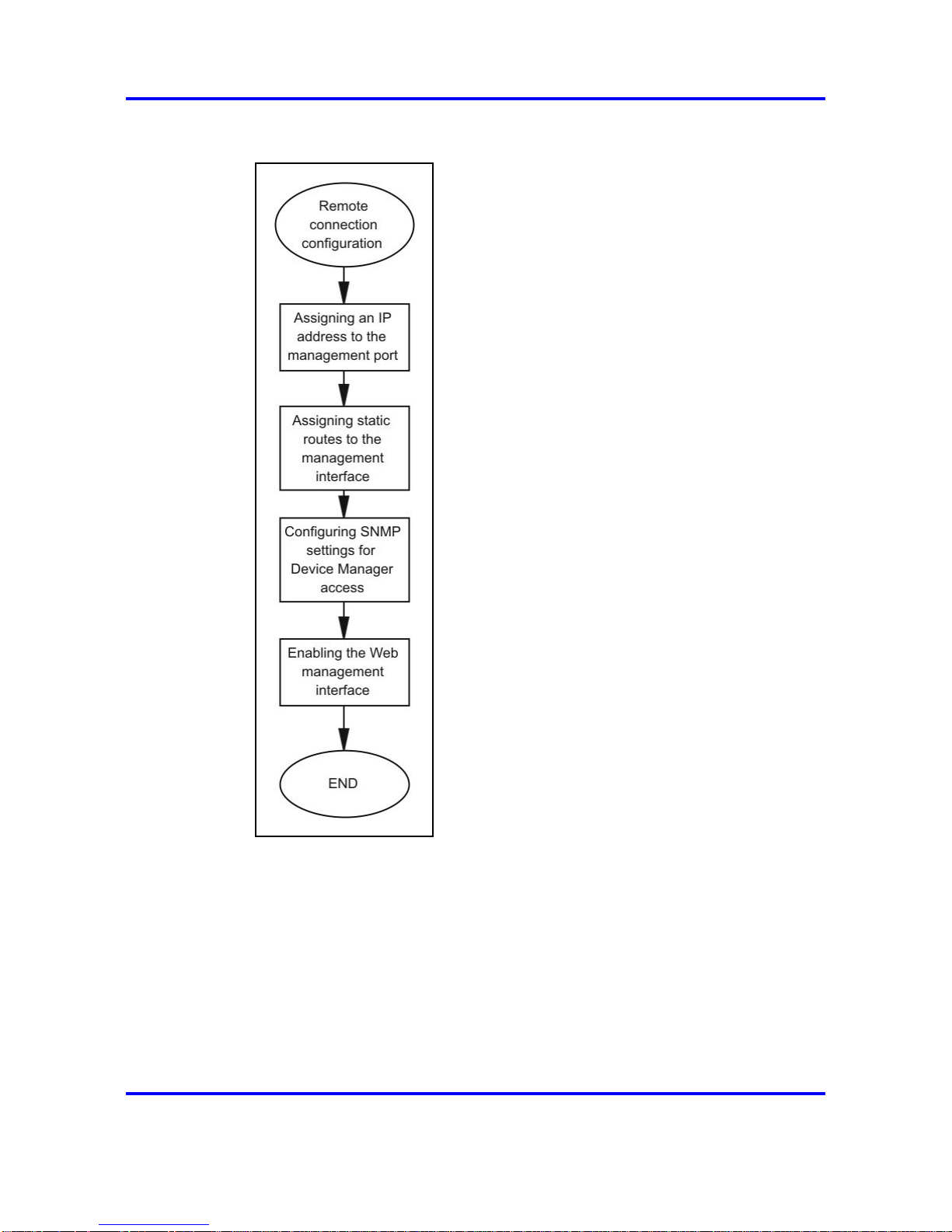
96 Remote connection configuration using Device Manager
Figure 10
Remote connection configuration procedures
Remote connection configuration navigation
• “Assigning an IP address to the management port” (page 97)
• “Assigning static routes to the management interface” (page 97)
• “Configuring SNMP settings for Device Manager access” (page 99)
• “Enabling the Web management interface” (page 101)
Nortel Ethernet Routing Switch 8600
Commissioning
NN46205-319 01.01 Standard
30 May 2008
Copyright © 2008 Nortel Networks
.
Page 97

Assigning static routes to the management interface 97
Assigning an IP address to the management port
Assign an IP address to the management port to use it for out-of-band
(OOB) management. The standby IP must be in the same subnet as the
master IP. Create a virtual management port in addition to the physical
management ports on the switch management modules.
Procedure steps
Step Action
1 In the main Device Manager window, select the management
port.
2 From the Device Manager toolbar, select Edit, Mgmt Port.
The Mgmt Port dialog box appears with the Mgmt Port-IP tab
displayed.
3 In the Addr box, type the required IP address for the
management port.
4 In the Mask box, type the subnet mask.
5 Click Apply.
6 Click Close.
7 From the Device Manager toolbar, select Edit, Chassis.
The Chassis dialog box appears with the System tab displayed.
8 In the VirtualIPAddr box, enter the IP address you want to
configure as the virtual address.
9 In the VirtualNetMask box, enter the subnet mask.
10 Click Apply.
--End--
Assigning static routes to the management interface
Assign a static route to specify a gateway address route for the
management interface. You can specify up to four static routes for the
management interface.
Procedure steps
Step Action
1 From the Device Manager menu bar, choose IP, IP -
GlobalRouter (vrf 0)...
The IP dialog box appears with the Globals tab displayed.
2 Click Static Routes .
Nortel Ethernet Routing Switch 8600
Commissioning
NN46205-319 01.01 Standard
30 May 2008
Copyright © 2008 Nortel Networks
.
Page 98

98 Remote connection configuration using Device Manager
The Static Routes tab appears.
3 Click Insert.
The Insert Static Routes dialog box appears.
4 Select the owner virtual router and forwarder (VRF).
5 In the Dest box, type the IP address.
6 In the Mask box, type the mask.
7 In the NextHop box, type the IP address of the router through
which you access the specified route.
8 Select the next hop VRF ID if configuring an interVRF static
route.
9 In the Metric box, type the HopOrMetric value.
10 In the Preference box, select the route preference.
11 Select Enable.
12 Select the LocalNextHop option if creating Layer 3 static routes.
13 Click Insert.
The new route appears in the Static Routes tab
--End--
Variable definitions
Use the data in the following table to configure the Insert Static Routes
dialog box.
Variable Value
OwnerVrfId Configures the owner VRF ID of the
static route.
Dest Configures the destination IP address
of this route. An entry with a value of
0.0.0.0 is the default route. Multiple
routes to a single destination can
appear in the table, but access to
such multiple entries depends on the
network management protocol table
access mechanisms.
Mask Is route network mask with the
destination address before the switch
compares the mask to the value in the
Dest box.
Nortel Ethernet Routing Switch 8600
Commissioning
NN46205-319 01.01 Standard
30 May 2008
Copyright © 2008 Nortel Networks
.
Page 99

Configuring SNMP settings for Device Manager access 99
Variable Value
NextHop Configures the IP address of the next
hop of this route. In the case of a
route bound to an interface realized
through a broadcast media, the value
of this box is the agent IP address on
that interface.
NextHopVrfId Indicates the next hop VRF ID in
interVRF static-route configuration.
Enable Initializes the static route.
Metric Configures the primary routing metric
for this route.
Preference Indicates the route preference of
this entry. If you can use more than
one route to forward IP traffic, the
switch uses the route with the highest
preference. The higher the number,
the higher the preference.
LocalNextHop If you select this variable, this box
indicates the static route is active
only if you configure the switch with
a local route to the network. If you
do not select this variable, this box
indicates the static route is active if
you configure the switch with a local
route or dynamic route.
Configuring SNMP settings for Device Manager access
Use this procedure to configure important communication parameters such
as the polling interval, timeout, and retry count. You can configure these
parameters before or after you open a device.
Device Manager automatically determines the software version of the
device you select.
Procedure steps
Step Action
1 From the initial Device Manager window menu bar, select
Device, Properties, Devices.
A list of IP addresses for configured devices appears.
2 Select the IP address for the device you want to edit.
3 Click Edit.
The Device Manager Properties dialog box appears.
Nortel Ethernet Routing Switch 8600
Commissioning
NN46205-319 01.01 Standard
30 May 2008
Copyright © 2008 Nortel Networks
.
Page 100

100 Remote connection configuration using Device Manager
4 Select the properties you want to change and configure their
values.
5 Click OK.
--End--
Variable definitions
Use the data in the following table to configure the Properties dialog box.
Variable Value
Status Interval Interval you use to gather statistics
and status information (default is 20
seconds).
(IfTraps, Status Interval) The interval, in seconds, you use
to gather statistics and status
information. Configure this value if you
select the Register for Traps box.
Hotswap Detect every The number of intervals at which
Device Manager checks for module
hot swaps.
Enable If you select this variable, Device
Manager polls the switch according
to the settings you select prior to the
Enable box.
Retry Count If Device Manager cannot transmit
polling information at start up, the
number of times Device Manager
retransmits polling information.
Timeout Length of the retry for each polling
waiting period. If you access the
device through a slow link, you can
increase the timeout interval and
change the retransmission strategy to
superlinear.
Trace If you select this variable, you can
perform trace routes.
Register for Traps If you select this variable, Device
Manager registers a trap.
Listen for Traps If you select this variable, Device
Manager monitors for a trap.
Max Traps in Log The specified number of traps that
can exist in the trap log. The default is
500.
Nortel Ethernet Routing Switch 8600
Commissioning
NN46205-319 01.01 Standard
30 May 2008
Copyright © 2008 Nortel Networks
.
 Loading...