

Page 1

Compact ICS 6.1
Return
to Menu
Installer Guide
Norstar and Meridian are trademarks of Nortel Networks
© Copyright Nortel Networks 2003
1-800-4 NORTEL
www.nortel.com/norstar
P0603539 02
Printed in Canada
Page 2

Page 3

RTable of Contents
Regulations 13
Installation Safety warning 13
Safety and installation 14
Important safety instructions 15
North American regulations 17
Telecommunication Registration 17
Federal Communication Commission (FCC) Notice Radio/TV
interference 18
Devices intended to be connected to the Public Switched Tele-
phone Network 18
US 18
Canada 20
Signaling method 21
Ringer Equivalence Number 21
Hearing aid compatibility (HAC) 22
Use of a music source 22
Programming emergency numbers 22
Limited Warranty 23
Exclusions 23
International Regulatory Information 24
What’s new with Norstar 25
New features for version 6.1 25
Welcome to ISDN 27
Comparing ISDN to Analog 27
BRI ISDN service 28
ISDN layers 29
ISDN Bearer capability 29
Services and features for ISDN BRI 30
ISDN hardware 32
Clock Source for ISDN Cards 35
Other ISDN BRI equipment 36
ISDN standards compatibility 37
Planning your ISDN network 37
Ordering ISDN BRI 37
P0603539 02 Compact ICS 6.1 Installer Guide
Page 4

iv /
ISDN programming 39
Programming ISDN equipment 42
Networking with Norstar 47
The big picture 47
Norstar behind a PBX 47
Trunks and target lines 48
Loop start trunks 48
BRI trunks 50
Target lines 50
Remote system access 51
Remote access on loop start trunks 51
Networking features 52
Security 52
Transparent dialing plan 55
Data Solutions 57
Examples of ISDN Scenarios 57
ISDN applications 57
Video conferencing and video telephony 57
Desktop conferencing 57
File transfer 57
Telecommuting 58
Group 4 fax 58
Remote LAN access 58
Leased line backup 58
LAN to LAN bridging 58
Internet and database access 58
Planning the installation 59
Planning checklist 59
Equipment and supplies 59
Optional equipment 60
Equipment for installing the ICS 60
Location requirements 61
Electrical requirements 61
Internal wiring requirements 62
Spacing requirements 63
Compact ICS 6.1 Installer Guide P0603539 02
Page 5

Upgrading your system 65
Upgrading a restricted Feature Cartridge 66
Upgrading from 16 telephones to 24 telephones 66
Upgrading to Compact ICS 6.1 67
Upgrading Expansion Cartridge for BRI Card installation 68
Installation 69
Installation checklist 70
Testing the ISDN network connection 72
Mounting the ICS 73
Installing the cartridges 75
Removing the cover 77
Installing the Feature Cartridge 78
Terminating resistors on BRI-ST Cards 79
Installing Trunk Cartridges 81
Installing the Expansion Cartridge 84
Connecting the wiring 87
Connecting the wiring for a Compact ICS 87
Connecting the wiring to the distribution panel 88
Wiring charts 88
BRI Wiring charts 96
Installing Norstar telephones 102
Installing the emergency telephone 102
Installing the device that uses the I-ATA 103
Installing Business Series Terminals 104
Installing Norstar telephones 106
Installing ISDN terminal equipment 109
S or T wiring for terminal equipment 109
S or T extension wiring configurations 109
U-LT wiring for terminal equipment 110
Installing optional equipment 112
Auxiliary ringer (customer supplied) 112
External music source (customer supplied) 112
External paging system (customer supplied) 113
Powering up the system 115
/ v
Programming 117
Programming overview 117
P0603539 02 Compact ICS 6.1 Installer Guide
Page 6

vi /
Profile, Dialpad and Startup programming 118
Installer or System Coordinator Plus programming 119
System Coordinator programming 120
Admin/Basic programming 121
Programming tools 122
Telephones 122
The programming overlay 122
Exiting programming 127
Viewing your programming updates 127
Entering numbers 128
Copying telephone programming 128
Profiles and Dialpads 132
Profile programming 132
Dialpad programming 135
Startup programming 136
Performing Startup 136
Programming 139
Entering programming for installers 140
Entering programming for system coordinators 140
Entering programming using other passwords 141
Programming sequence 141
Terminals&Sets 142
Line access 142
Line assignment 143
Line pool access 144
Prime line 145
Intercom keys 146
Answer DNs 146
OLI # 147
Capabilities 148
ATA settings 150
Name 151
User prefernces 151
Restrictions 152
Telco features 158
Caller ID set 158
Lines 161
Trunk/Line data 161
Copying Trunk and Line data 162
Trunk type 162
Line type 163
Compact ICS 6.1 Installer Guide P0603539 02
Page 7

Dial mode 164
Prime set 164
Auto privacy 165
Trunk mode 165
Ans mode 166
Ans with DISA 166
Aux. ringer 167
Full AutoHold 167
LossPkg 168
Rec’d # 169
Name 170
Restrictions 170
Restrn filters 170
Line restrns 171
Remote restrns 172
Telco features 173
Services 174
Ringing service 175
Restrn service 178
Routing service 179
Routes 180
Dest codes 181
Setting up a route for local calling 183
Setting up a route for long distance calling 185
Adding a long distance carrier access code 187
Programming for least cost routing 188
Night sched 190
Using dialing restrictions with routing 191
Common settings 192
Sys speed dial 195
Passwords 196
COS pswds 196
Call log pswds 198
Programming pswds 198
Installer 198
SysCoord+ 198
SysCoord 199
Basic 199
IRAD pswd 199
Hospitality password 200
Silent Monitor password 201
/ vii
P0603539 02 Compact ICS 6.1 Installer Guide
Page 8

viii /
Time&Date 202
System prgming 203
Hunt groups 203
Change DNs 211
Featr settings 212
DRT to prime 214
DRT delay 214
Host delay 218
Link time 218
Direct-Dial 223
CAP/KIM assgn 225
Access codes 227
Line pool codes 228
Park prefix 228
External code 229
Direct-dial # 230
Auto DN 230
DISA DN 231
Auto Attendant 232
Remote access 234
Rec’d # length 237
DN length 238
Network Name Display 241
Intrl modem 242
Alarm reporting 243
Release Reasons 245
Hospitality Services 246
SM sets 248
ETSI: Network features (profile 2) 249
Network Call Diversion 249
Malicious call identification (MCID) 252
Telco features 253
VMsg centr tel#s 253
Outgoing Name and Number Blocking 253
Software Keys 255
SysID 255
Password Keys 255
Hardware 256
Cd1-KSU 257
Discon timer 258
Loops 258
Compact ICS 6.1 Installer Guide P0603539 02
Page 9

Loop 258
Type 259
Lines 259
No SPIDs assignd 260
# of B-channels 260
Network DNs 261
Call type 261
D-packet servc 262
D-packet servc 262
Lp201 262
TEIs 262
No TEIs on loop 262
Sampling 263
DNs on Loop 201 263
Assign DNs 263
Loop DN 264
I-RAD 265
Connecting to the I-RAD 266
Testing 267
/ ix
Troubleshooting 269
Getting ready 270
Types of problems 270
General troubleshooting procedure 271
Problems with telephones 272
Norstar telephone has faulty buttons, display, handset or other
hardware problems 272
Norstar telephone display unreadable 272
Telephone dead 273
Emergency telephone dead 274
Problems with lines 275
Calls cannot be made (but can be received) 275
Dial tone absent on external lines 276
Hung lines at a telephone 276
Auto-answer line rings at a telephone 277
Prime telephone gets misdialed calls 278
Selected line shows Not in service or Not available 279
Selected line pool shows No free lines 279
Problems with the I-ATA 280
P0603539 02 Compact ICS 6.1 Installer Guide
Page 10

x /
Calls do not ring and caller does not receive busy tone 280
I-ATA is always busy 280
Calls cannot be answered (or dial tone is not present when
making calls) 281
Calls cannot be made (but dial tone is present) 281
Problems with optional equipment 283
Auxiliary ringer 283
External paging 284
Music on Hold/Background Music trouble 284
KIM not working 285
Problems with Trunk Cartridges 287
Trunk Cartridge trouble 287
Problems with BRI service 288
The BRI card is connected to the ISDN network
(U-loop) but the LED for one of more loops is not lit 288
Out of service is displayed when a BRI line is selected (LED for
loop is lit) 289
All the LEDs on a BRI Card are flashing 289
Caller hears one ring and then a fast busy signal when placing
a call on a BRI line 290
Problems with the NT1 291
ICS down 292
Problems for network or remote users 294
Remote feature code gets no response 294
Dialed number gets ringback and the wrong person 294
Dialed number gets stuttered dial tone instead of ringback 295
Dialed number gets dial tone instead of ringback 295
Dialed number gets busy tone 296
Dialed number does not get through 296
Dialed DISA number gets ringback instead of stuttered dial
tone 297
Dialed DISA number gets dial tone instead of stuttered dial tone
298
DISA user gets overflow tone when entering COS password
298
Dialed feature code gets overflow tone 300
Dialed feature code gets busy tone 301
Line pool access code gets overflow tone 301
Line pool access code gets ringback 302
Line pool access code gets busy tone 302
Dialed number gets no response 303
Compact ICS 6.1 Installer Guide P0603539 02
Page 11

Maintenance 305
Maintenance overview 305
Beginning a Maintenance session 306
System version 307
Checking the version of the system 307
Port/DN status 308
Identifying a device connected to the system 309
Checking the version number of the device 310
Checking the state of the device 311
Disabling a device 312
Enabling the device 313
Returning to the beginning 313
Module status 314
Looking at the module inventory 314
Checking the number of Trunk Cartridges attached to a module
314
Checking the state of a module 315
Checking the state of a cartridge 316
Disabling a module or its cartridges 316
Enabling a module or its cartridges 316
Returning to the beginning 317
System test log 318
Checking the items in the log 318
Checking the current alarm 319
Checking when each item in the log occurred 319
Checking the number of consecutive repetitions of an event or
alarm 319
Erasing the log 319
System administration log 320
Checking the items in the log 320
Checking the current alarm 320
Checking when each item in the log occurred 321
Erasing the log 321
Provisioning 322
Cd1-KSU 322
Alarm codes 323
If you see an alarm code 323
Alarm troubleshooting 325
Event messages 328
/ xi
P0603539 02 Compact ICS 6.1 Installer Guide
Page 12

xii /
Dealing with event messages 328
Significant event messages 328
Tests 334
Loopback test 334
Usage Metrics 337
Hunt groups 337
Maintenance records 339
Recording information on the Maintenance records 339
Version number record 340
System test log record 341
System administration log record 342
Specifications 343
Glossary 347
SIndex 367
Backup programming overlays 389
Compact ICS 6.1 Installer Guide P0603539 02
Page 13

Regulations
Installation Safety warning
Only qualified persons should service this
system.
The installation and service of this hardware is to
be performed only by service personnel having
appropriate training and experience necessary to
be aware of hazards to which they are exposed in
performing a task and of measures to minimize
the danger to themselves or other persons.
Electrical shock hazards from the
telecommunication network and AC mains are
possible with this equipment. To minimize risk to
service personnel and users, the system must be
connected to an outlet with a third-wire ground.
Service personnel must be alert to the possibility
of high leakage currents becoming available on
metal system surfaces during power line fault
events near network lines. These leakage
currents normally safely flow to Protective Earth
ground via the power cord.
Therefore, it is mandatory that connection to an
earthed outlet is performed first and removed last
when cabling the unit. Specifically, operations
requiring the unit to be powered down must have
the network connections (central office lines)
removed first.
This equipment meets all applicable requirements of CSA and UL safety
standards for North America and relevant EN60950 specifications for
European and other markets.
P0603539 02 Compact ICS 6.1 Installer Guide
Page 14

14 / Regulations
Safety and installation
The shock hazard symbol within an equilateral
triangle is intended to alert personnel to electrical
shock hazard or equipment damage.
The following precautions should also be
observed when installing telephone equipment.
• Never install telephone wiring during a lightning
storm.
• Never install telephone jacks in wet locations unless
the jack is specifically designed for wet locations.
• Never touch uninsulated telephone wires or terminals
unless the telephone line has been disconnected at
the network interface.
• Use caution when working with telephone lines.
The exclamation point within an equilateral
triangle is intended to alert the user to the
presence of important operating and maintenance
(servicing) instructions in the literature
accompanying the product.
This symbol (if applicable) on the product is used to identify the following
important information:
For equipment with internal power supplies
• Mains nominal AC voltage 110-120 V~; 60Hz
• Mains nominal AC voltage 220-240 V~; 50Hz
For equipment with external power supplies
• Must be powered from an approved Class 2 power source.
For current ratings, refer to product specific documentation and product
labels.
Compact ICS 6.1 Installer Guide P0603539 02
Page 15

Regulations / 15
Important safety instructions
When using your telephone equipment, basic safety precautions should
always be followed to reduce the risk of fire, electric shock and injury of
persons, including the following:
• Follow the warnings and instructions marked on the product.
• Unplug this product from the wall outlet before cleaning. Do not use
liquid cleaners or aerosol cleaners. Use a damp cloth for cleaning.
• Do not use this product near water, for example, near a bathtub, wash
bowl, kitchen sink, or laundry tub, in a wet basement or near a
swimming pool.
• Do not place this product on an unstable cart, stand or table. The
product may fall, causing serious damage to the product.
• This product should never be placed near or over a radiator or heat
register. This product should not be placed in a built-in installation
unless proper ventilation is provided.
• Do not allow anything to rest on the power cord. Do not locate this
product where the cord will be abused by persons walking on it.
• Do not overload wall outlets and extension cords as this can result in
the risk of fire or electric shock.
• Never spill liquid of any kind on the product.
• To reduce the risk of electric shock, do not disassemble this product,
but have it sent to a qualified service person when service or repair
work is required.
• Unplug this product from the wall outlet and refer servicing to
qualified service personnel under the following conditions:
a. When the power supply cord or plug is damaged or frayed.
b. If the product has been exposed to rain, water or liquid has been
spilled on the product, disconnect and allow the product to dry out
to see if still operates; but do not open up the product.
c. If the product housing has been damaged.
d. If the product exhibits a distinct change in performance.
• Avoid using telephone equipment during an electrical storm. There
may be a remote risk of electric shock from lightning.
P0603539 02 Compact ICS 6.1 Installer Guide
Page 16

16 / Regulations
• Do not use the telephone equipment to report a gas leak in the vicinity
of the leak.
• To eliminate the possibility of accidental damage to cords, plugs,
jacks, and the telephone equipment, do not use sharp instruments
during the assembly procedures.
• Do not insert the plug at the free end of the handset cord directly into
a wall or baseboard jack. Such misuse can result in unsafe sound levels
or possible damage to the handset.
• Disconnect telecommunications lines before unplugging main power
cord.
• Save these instructions
Compact ICS 6.1 Installer Guide P0603539 02
Page 17

North American regulations / 17
North American regulations
Telecommunication Registration
Norstar equipment meets all applicable requirements of both Industry
Canada CS-03 and US Federal Commission FCC Part 68 and has been
registered under files Industry Canada 332D-5980A and FCC
US:AB6KF15B20705 (key system), US:AB6MF15B20706 (hybrid
system), and US:AB6PF15B23740 (PBX system). Connection of the
Norstar telephone system to the nationwide telecommunications network is
made through a standard network interface jack that you can order from
your local telecommunications company. This type of customer-provided
equipment cannot be used on party lines or coin lines.
Before installing this equipment, users should ensure that it is permissible
to be connected to the facilities of the local telecommunications company.
The equipment must also be installed using an acceptable method of
connection. The customer should be aware that compliance with the above
conditions may not prevent degradation of service in some situations.
Repairs to certified equipment should be made by an authorized
maintenance facility designated by the supplier. Any repairs or alterations
made by the user to this equipment, or equipment malfunctions, may give
the telecommunications company cause to request the user to disconnect
the equipment. Users should ensure for their own protection that the
electrical ground connections of the power utility, telephone lines and
internal metallic water pipe system, if present, are connected together. This
precaution may be particularly important in rural areas.
Users should not attempt to make such
connections themselves, but should contact
the appropriate electric inspection authority, or
electrician.
P0603539 02 Compact ICS 6.1 Installer Guide
Page 18

18 / North American regulations
Federal Communication Commission (FCC) Notice Radio/TV interference
This equipment, has been tested and found to comply with the limits for a
Class A digital device, pursuant to Part 15 of the FCC Rules. These limits
are designed to provide reasonable protection against harmful interference
when the equipment is operated in a commercial environment. This
equipment generates, uses, and can radiate radio frequency energy and, if
not installed and used in accordance with the instruction manual, may
cause harmful interference to radio communications. Operation of this
equipment in a residential area is likely to cause harmful interference in
which case the user will be required to correct the interference at his own
expense.
Changes or modifications not expressly approved by the party responsible
for compliance could void the user’s authority to operate the equipment.
Devices intended to be connected to the Public Switched Telephone Network
State and local requirements for support of
Emergency 911 Dialing service by Customer
Premises Equipment vary. Consult your local
telecommunications service provider
regarding compliance with applicable laws
and regulations.
US
This telephone equipment complies with Part 68, FCC Rules for direct
connection to the Public Switched Telephone Network (The FCC
registration number appears on a label affixed to the ICS).
Your connection to the telephone line must comply with these FCC Rules:
• Use only an FCC Standard network interface jacks and FCC compliant
line cord and plug to connect this equipment to the telephone line.
Compact ICS 6.1 Installer Guide P0603539 02
Page 19

North American regulations / 19
• If a network interface jack is not already installed in your location, you
can order one from your telephone company. Order the following
network jacks along with the corresponding Facility Interface Code
(FIC):
Trunk REN USOC SOC FIC
GATC LSDS (NT7B69AAAA) 0.0 A
0.0 B
Loop Start/Disconnect Supervision
(LS/DS)- NT7B75GA-93
GATC CI (NT7B75AAC) 0.0 A
Call Information (CI)- NT5B41GA-93 AC
BRI-U2 and BRI-U4 Cards
NT7B86GB-93 and
NT7B87GB-93
BRI-ST - NT7B76GY-93
(when connected to an NT1 which
has a U interface to the telephone
network)
AC
1.5B
DC 0.3
0.0 B
1.5B
DC 0.3
— RJ49C 6.0Y 02IS5
— RJ49C 6.0Y 021S5
RJ21X 9.0F 02LS2
RJ21X 9.0F 02LS2
RJ21X 9.0F 02LS2
RJ21X 9.0F 02LS2
In some states, customers are permitted to install their own jacks.
• The equipment cannot be used with or connected to a party line or a
public coin phone service provided by the telephone company.
Connection to Party Line Service is subject to state tariffs. Contact the
Public State Utility Commission, Public Service Commission or
Corporation Commission for information.
• It is no longer necessary to notify the Telephone Company of your
system Registration and REN numbers. However, you must provide
this information to the telephone company if they request it.
P0603539 02 Compact ICS 6.1 Installer Guide
Page 20

20 / North American regulations
• If this equipment causes harm to the telephone network, the telephone
company will notify you in advance that temporary discontinuance of
service may be required. If advance notice is not practical, the
telephone company will notify the customer as soon as possible. Also,
you will be advised of your right to file a complaint with the FCC if
you believe it necessary.
• The telephone company may make changes in its facilities, equipment,
operations or procedures that could affect the operation of the
equipment. If this happens the telephone company will provide
advance notice in order for you to make necessary modifications to
maintain uninterrupted service.
• Do not attempt to repair this equipment yourself. If trouble is
experienced with this equipment, please refer to the repair and
warranty information, noted below. If the equipment is causing harm
to the telephone network, the telephone company may request that you
disconnect the equipment until the problem is resolved.
Canada
Before installing this equipment, users should ensure that it is permissible
to be connected to the facilities of the local telecommunications company.
The equipment must also be installed using an acceptable method of
connection. The customer should be aware that compliance with the above
conditions may not prevent degradation of service in some situations.
Repairs to certified equipment should be made by an authorized Canadian
maintenance facility designated by the supplier. Any repairs or alterations
made by the user to this equipment, or equipment malfunctions, may give
the telecommunications company cause to request the user to disconnect
the equipment.
Compact ICS 6.1 Installer Guide P0603539 02
Page 21

North American regulations / 21
Users should ensure for their own protection that the electrical ground
connections of the power utility, telephone lines and internal metallic water
pipe system, if present, are connected together. This precaution may be
particularly important in rural areas.
Caution
Users should not attempt to make such connections
themselves, but should contact the appropriate electric
inspection authority, or electrician, as appropriate
This Class A digital apparatus meets all requirements of the Canadian
Interference-Causing Equipment Regulations as specified in the Industry
Canada Standard ICES-003.
Signaling method
The equipment allows signaling in DTMF tones. It can complete calls to
local and long distance lines and can also complete long distance calls via
computer phone systems such as MCI or SPRINT. This equipment is
capable of providing access to interstate providers of operator services
through the use of access codes. Modification of this equipment by call
aggregators to block access dialing codes is a violation of the Telephone
Operator Consumers Act of 1990.
Ringer Equivalence Number
US
The FCC Registration information on the product label, includes a Ringer
Equivalence Number (REN) which is used to determine the number of
devices you may connect to your phone line. A high total REN may prevent
ICSs from detecting ringing in response to an incoming call and may make
placing calls difficult. In most, but not all areas, the sum of the RENs
should not exceed five (5.0). To be certain of the number of devices that
may be connected to a line, as determined by the total RENs, contact the
local telephone company.
Note: RENs are associated with loop start and ground start ports. Do not
use for E&M or digital ports.
P0603539 02 Compact ICS 6.1 Installer Guide
Page 22

22 / North American regulations
Canada
The Ringer Equivalence Number (REN) assigned to each terminal device
provides an indication of the maximum number of terminals allowed to be
connected to a telephone interface. The termination on an interface may
consist of any combination of devices subject only to the requirement that
sum of the ringer equivalence numbers of all the devices does not exceed 5.
Hearing aid compatibility (HAC)
The telephone station sets are compatible with hearing aids equipped with
an appropriate telecoil and is compliant with the requirements of the
Americans with Disabilities Act (ADA).
Use of a music source
In accordance with US, Canadian and international copyright laws, a
license may be required from the American Society of Composers, Authors
and Publishers, or other composers’ or performing rights organization if
Radio, TV or other broadcasts to the public are transmitted through the
Music On Hold or Background Music features of this telecommunication
system.
Programming emergency numbers
When programming emergency numbers and/or making test calls to
emergency numbers:
1. Remain on the line and briefly explain to the dispatcher the reason for
calling before hanging up.
2. Perform such activities in the off-peak hours, such as early mornings
or late evenings.
Substitution of non-approved equipment will void the NORTEL warranty.
Address for warranty and repairs
in the US:
Nortel
640 Massman Drive
Nashville TN 37210
For more information call 1-800-4NORTEL
Compact ICS 6.1 Installer Guide P0603539 02
Address for warranty and repairs
in Canada:
Nortel
30 Norelco Drive
Weston, Ontario M9L 2X6
Page 23

Limited Warranty / 23
Limited Warranty
Nortel Networks warrants this product against defects and malfunctions
during a one (1) year period from the date of original purchase. If there is
a defect or malfunction, Nortel Networks shall, at its option, and as the
exclusive remedy, either repair or replace the telephone set at no charge, if
returned within the warranty period.
If replacement parts are used in making repairs, these parts may be
refurbished, or may contain refurbished materials. If it is necessary to
replace the telephone set, it may be replaced with a refurbished telephone
of the same design and color. If it should become necessary to repair or
replace a defective or malfunctioning telephone set under this warranty, the
provisions of this warranty shall apply to the repaired or replaced telephone
set until the expiration of ninety (90) days from the date of pick up, or the
date of shipment to you, of the repaired or replacement set, or until the end
of the original warranty period, whichever is later. Proof of the original
purchase date is to be provided with all telephone sets returned for warranty
repairs.
Exclusions
Nortel Networks does not warrant its telephone sets to be compatible with
the equipment of any particular telephone company. This warranty does
not extend to damage to products resulting from improper installation or
operation, alteration, accident, neglect, abuse, misuse, fire or natural causes
such as storms or floods, after the telephone is in your possession.
Nortel Networks shall not be liable for any incidental or consequential
damages, including, but not limited to, loss, damage or expense directly or
indirectly arising from the customers use of or inability to use this
telephone, either separately or in combination with other equipment. This
paragraph, however, shall not apply to consequential damages for injury to
the person in the case of telephones used or bought for use primarily for
personal, family or household purposes.
This warranty sets forth the entire liability and obligations of Nortel
Networks with respect to breach of warranty, and the warranties set forth
or limited herein are the sole warranties and are in lieu of all other
warranties, expressed or implied, including warranties or fitness for
particular purpose and merchantability.
P0603539 02 Compact ICS 6.1 Installer Guide
Page 24

24 / International Regulatory Information
International Regulatory Information
The CE Marking on this equipment indicates
compliance with the following:
This device conforms to Directive 1999/5/EC on
Radio Equipment and Telecommunications
Terminal Equipment as adopted by the European
Parliament And Of The Council.
This is a class A product. In a domestic environment this product may
cause radio interference in which case the user may be required to take
adequate measures.
Information is subject to change without notice. Nortel Networks reserves
the right to make changes in design or components as progress in
engineering and manufacturing may warrant. This equipment has been
tested and found to comply with the European Safety requirements EN
60950 and EMC requirements EN 55022 (Class A) and EN 55024. These
EMC limits are designed to provide reasonable protection against harmful
interference when the equipment is operated in a commercial and light
industrial environment.
WARNING
This is a class A product. In a domestic environment this
product may cause radio interference in which case the
user may be required to take adequate measures. The
above warning is inserted for regulatory reasons. If any
customer believes that they have an interference
problem, either because their Nortel Networks product
seems to cause interference or suffers from interference,
they should contact their distributor immediately. The
distributor will assist with a remedy for any problems
and, if necessary, will have full support from Nortel
Networks.
Compact ICS 6.1 Installer Guide P0603539 02
Page 25

What’s new with Norstar
The Norstar Compact ICS 6.1 software includes several new features and
a few functionality changes.
New features for version 6.1
• Key Indicator Module (KIM) and T7316E Business Series Terminal
(BST) create a Central Answering Position (CAP).
These two pieces of hardware are designed to replace the M7324/CAP
setup. The T7316E can also be deployed as a stand-alone unit, and
works the same way as previous versions of the T7316 with some
minor changes, including an active handsfree key below the main
dialpad. (CAP/KIM assgn on page 225)
The KIM can be used in two configurations. The ordinary KIM
(OKIM) has the same functionality as the current unassigned CAP
module. The enhanced KIM (eKIM) supports multiple lines, including
target lines, and hunt group appearances.
Up to four KIMs can be attached to a T7316E, without requiring a
supplementary power supply. A T7316E can only support a maximum
of four eKIMs, however, it can support up to nine OKIMs, with the
addition of a station auxiliary power supply (SAPS). The system can
support one CAP with an eKIM. This number will include any T7324based CAP installations you might already have. The system can
support any number of CAPS using OKIMs.
T7316E telephones and KIMs also provide call-specific icons to make
call tracking easier.
You cannot program Answer DNs onto a KIM.
• destination code enhancements
— 12-digit destination code: You can specify up to 12 digits as a
destination code, which allows you to support user expectations of
dialing requirements for existing systems. For instance, if your
users are used to dialing 91XXX-XXX-XXXX for a long distant
call, they can continue to do so, so you can provide a seamless
transition to network dialing. (Dest codes on page 181)
— multiple least-cost routing: When you specify a schedule other
than Normal for a destination code, you can specify up to three
P0603539 02 Compact ICS 6.1 Installer Guide
Page 26

26 / What’s new with Norstar
possible routes the call can access, in order of preference. The
system tries the first route, and if that route is not available, the
system moves to the next route, and so on. (Multiple least cost
routing on page 189)
• Silent monitor for hunt groups
Your Hunt group supervisors can now monitor hunt group calls, either
silently, or by providing a conference tone to indicate that the call is
being monitored (Monitoring Hunt groups on page 210). Other new
functionality has been added to allow you to determine which
telephones will be allowed to silent monitor (Capabilities on page
148), how many monitoring telephones your system will allow (SM
sets on page 248), and what password is required to enter a monitoring
session (Silent Monitor password on page 201). Refer to the Modular
ICS 6.1 System Coordinator Guide for a detailed description about
how to use the feature.
• CLID display enhancements: display an incoming call CLID on a
telephone with activated CLID display, where a call is currently
active.
Compact ICS 6.1 Installer Guide P0603539 02
Page 27

Welcome to ISDN
This chapter provides you with some background information about ISDN
and also includes information about:
• Analog vs. ISDN
• Type of ISDN service
• ISDN layers
• ISDN Bearer capability
• Services and features for ISDN BRI
• ISDN hardware
• ISDN standards compatibility
Integrated Services Digital Network (ISDN) technology provides a fast,
accurate and reliable means of sending and receiving voice, data, images,
text, and other information through the telecom network.
ISDN uses existing analog telephone wires and divides them into separate
digital channels, which dramatically increases the bandwidth.
ISDN uses a single transport to carry multiple information types. What
once required separate networks for voice, data, images, or video
conferencing is now combined onto one common high-speed transport.
Note: Nortel endeavours to test all variations of ISDN BRI and PRI on
Norstar. However, due to the number of variations, this is not always
possible. Check with your service provider about compatibility.
Comparing ISDN to Analog
ISDN offers significantly higher bandwidth and speed than analog
transmission because of its end-to-end digital connectivity on all
transmission circuits. Being digital allows ISDN lines to provide better
quality signaling than analog POTS lines and ISDN out-of band data
channel signaling offers faster call set up and tear down.
While an analog line carries only a single transmission at a time, an ISDN
line can carry one or more voice, data, fax and video transmissions
simultaneously.
P0603539 02 Compact ICS 6.1 Installer Guide
Page 28

28 / Welcome to ISDN
An analog modem operating at 14.4 K takes about 4.5 minutes to transfer
a 1 MB data file and a 28.8 K modem takes about half that time. Using one
channel of an ISDN line, the transfer time is reduced to only one minute. If
two ISDN channels are used, transfer time is just 30 seconds.
When transmitting data, the connect time for an average ISDN call is about
three seconds per call, compared to about 21 seconds for the average
analog modem call.
BRI ISDN service
Basic Rate Interface (BRI) ISDN service provides lines where each line is
made up of separate channels known as B and D channels which transmit
information simultaneously.
BRI is known as “2B+D” because it consists of two B-channels and one
D-channel.
B channels
B channels are the bearer channel and are used to carry voice or data
information and have speeds of 64 kbps. Since each ISDN line (BRI) has
more than one B-channel, a user can perform more than one transmission
at the same time using a single ISDN line.
D channels
The standard signaling protocol is transmitted over a dedicated data
channel called the D-channel. The D-channel carries call setup and feature
activation information to the destination and has speeds of 16 kbps. Data
information consists of control and signal information and packet-switched
data such as credit card verification.
Compact ICS 6.1 Installer Guide P0603539 02
Page 29

Welcome to ISDN / 29
ISDN layers
ISDN layers refer to the standards established to guide the manufacturers
of ISDN equipment. The layers include both physical connections, such as
wiring and logical connections, which are programmed in computer
software.
When equipment is designed to the ISDN standard for one of the layers, it
works with equipment for the layers above and below it.
There are three layers at work in ISDN for Norstar. To support ISDN
service, all three layers must be working properly.
• Layer 1: A physical connection that supports fundamental signaling
passed between the ISDN network (your service provider) and the
Norstar Compact ICS. When the BRI card LED for a loop which is
used for a network connection is lit, layer 1 is functioning.
• Layer 2: A logical connection between the ISDN network (your
service provider) and the Norstar Compact ICS. Norstar has two of
these connections for each BRI line, one for each of the logical lines.
Without Layer 2, call processing is not possible and there is no dial
tone.
• Layer 3: Also a logical connection between the ISDN network (your
service provider) and the Norstar Compact ICS. For BRI lines, layer 3
is where call processing and service profile identifier (SPID)
information is exchanged. This controls which central office services
are available to the connection. For example, a network connection
can be programmed to carry data calls.
The system of layers is important when you are installing, maintaining, and
troubleshooting an ISDN system. See Problems with BRI service on page
288 for more information about working with the layers.
ISDN Bearer capability
Bearer capability describes the transmission standard used by the BRI line
so that it can work within a larger ISDN hardware and software network.
The bearer capability for BRI is voice/speech, 3.1 kHz audio, and data
(unrestricted 64 kbps, restricted 64 kbps, 56 kbps).
P0603539 02 Compact ICS 6.1 Installer Guide
Page 30

30 / Welcome to ISDN
Services and features for ISDN BRI
As part of an ISDN digital network, your Compact ICS supports enhanced
capabilities and features, including:
• faster call set up and tear down
• high quality voice transmission
• dial-up Internet and local area network (LAN) access
• video transmission
• network name display
• name and number blocking (BRI and analog)
• access to public protocols (NI-1 for BRI)
BRI services and features
• data transmission at speeds up to 128 kbps per loop (depending on the
bandwidth supported by your service provider)
• shared digital lines for voice and data ISDN terminal equipment
Norstar Basic Rate Interface (BRI) cards also support D-channel packet
service between a network and terminal connection. This allows you to add
applications, such as point-of-sale terminals, without additional network
connections.
Any analog or digital network connections can be shared by all Norstar
telephones, peripherals and applications, and ISDN terminal equipment
(TE).
Compact ICS supports the following ISDN services and features offered by
ISDN service providers:
• D-channel packet service to support devices such as transaction
terminals. Transaction terminals are used to “swipe” credit or debit
cards and transmit the information to a financial institution in data
packets.
• calling number identification (appears on both Norstar sets and ISDN
terminal equipment with the capability to show the information)
• Multi-Line Hunt or DN Hunting, which switches a call to another
ISDN line if the line usually used by the Network DN is busy.
Compact ICS 6.1 Installer Guide P0603539 02
Page 31

Welcome to ISDN / 31
• subaddressing of terminal equipment (TE) on the same BRI loop.
However, terminal equipment which supports sub-addressing is not
commonly available in North America.
Transmission of B-channel packet data is not supported by Compac tICS.
Contact your ISDN service provider for more information about these
services and features. Packages for ISDN service in North America are
described on page 38.
The terminal equipment (TE) connected to the Norstar system can use
some feature codes supported by the ISDN service provider. See ISDN
services and features in the Compact ICS 6.1 System Coordinator Guide
for more information.
Network name display
When your phone rings, this feature allows you to see the name of the
person who is calling you. This call information is only available from the
public network and must be activated on the public network side of the
switch.
Name and number blocking
This feature allows you to program a feature button with the code from the
CO that is used to suppress the outgoing name and/or number for your
telephone. For information about system programming of this feature, see
Outgoing Name and Number Blocking on page 253.
MCID (ETSI system feature)
The MCID feature allows you to use
information recorded on the central office database for an incoming call on
a specific line (EUROISDN lines, only).
The user must invoke the feature code without hanging up, and within 30
seconds (time varies on different networks) after the caller hangs up.
P0603539 02 Compact ICS 6.1 Installer Guide
²¡áà
to have call
Page 32

32 / Welcome to ISDN
Network Call Diversion (ETSI system feature)
This feature is a network function of ETSI E1 lines that allows forwarding
and redirection of calls outside the Norstar network when using an ETSI
ISDN line. Functionality is similar to that of External Call Forward (ECF).
NCD redirects calls using the same line on which they arrive. Call forward
is efficient since there is no need for additional outside lines.
ISDN hardware
To support connections to an ISDN network and ISDN terminal
equipment, your Compact ICS must be equipped with one or more BRI
Cards (BRI-U or BRI-ST).
BRI Card
The loops on BRI-U and BRI-ST Cards can be programmed to support
either network or terminal connections. This allows you to customize your
arrangement of lines, voice terminals, data terminals and other ISDN
equipment. This section describes some basic hardware configurations for
network and terminal connections for each loop type.
For detailed wiring information about BRI network and terminal
connections see Installation on page 69.
BRI-U2 and BRI-U4
A BRI-U2 Card supports two loops and the BRI-U4 supports four loops.
Each loop can be individually programmed to provide one of the following:
• a U-LT reference point connection for terminal equipment (TE) with
built-in NT1 functionality (U interface)
• a U-NT reference point connection for direct connection to an ISDN
network
BRI-ST Card
A BRI-ST Card provides four loops. Each loop can be individually
programmed as one of the following:
• an S reference point connection (S loop) to ISDN TE
• a T or S reference point connection (T loop or S loop) to an ISDN
network using an external NT1
Compact ICS 6.1 Installer Guide P0603539 02
Page 33

Welcome to ISDN / 33
U-LT reference point
The U-LT reference point connection provides a point-to-point digital
connection between Norstar and TE equipped with a U interface.
A U-LT loop supports up to eight ISDN DNs, which identify TE to the ICS.
point-to-point
U-LT
U interface TE
ICS
U-NT reference points
The U-NT reference point connection provides a point-to-point digital
connection between the ISDN network and the ICS.
A U-NT loop provides lines that can be used by all Norstar telephones,
peripherals and applications, and ISDN TE.
network
connection
ISDN
U-NT
ICS
U-NT and U-LT loops can be used in combination to provide D-packet
service for a point-of-sale terminal adapter (POSTA) or other D-packet
device. D-packet service is a 16 kbps data transmission service that uses the
D-channel of an ISDN line.
P0603539 02 Compact ICS 6.1 Installer Guide
Page 34

34 / Welcome to ISDN
Inspect FORWARD Callers
MXP
Inspect FORWARD Callers
MXP
Inspect FORWARD Callers
MXP
To deliver D-packet service, a network connection (U-NT) is programmed
to work with a terminal connection (U-LT). The loops must be on the same
physical card. For example, if the network connection is a loop found on
the BRI Card in Slot 1, the terminal connection must be a loop found on the
same card.
S reference point
The S reference point connection provides a point-to-point digital
connection between Norstar and ISDN terminal equipment (TE) that uses
an S interface.
S loops support up to seven ISDN DNs, which identify TE to the ICS.
ICS
point-to-point
S
S
ISDN TE
ISDN TE (with terminating resistors)
Inspect FORW
ARD Callers
Inspect FORWARD Callers
MXP
MXP
ISDN TE
Inspect FORWARD Callers
MXP
ISDN TE
(with terminating
resistors)
Compact ICS 6.1 Installer Guide P0603539 02
Page 35

Welcome to ISDN / 35
T reference points
The T reference point connections provide a point-to-point digital
connection between the ISDN network and Norstar.
A T loop provides lines that can be shared by all Norstar telephones,
peripherals and applications, and ISDN TE.
ISDN
Network connection
T
ICS
A T loop can be used in combination with an S loop to provide D-packet
service for a point-of-sale terminal adapter (POSTA) or other D-packet
device. D-packet service is a 16 kbps data transmission service that uses the
D-channel of an ISDN line.
To deliver D-packet service, a network connection (T loop) is programmed
to work with a terminal connection (S loop). The loops must be on the same
physical card. For example, if the network connection is a loop found on
the BRI Card in Slot 1, the terminal connection must be a loop found on the
same card
Clock Source for ISDN Cards
Systems with ISDN interfaces need to synchronize clocking with the ISDN
network and any connected ISDN terminal equipment. Clocking
synchronization is supported by a Services Cartridge.
The Compact ICS derives timing from the network using
U-NT and T reference points (loops). Terminal equipment on U-LT and S
reference points (loops) derive timing from the ICS.
P0603539 02 Compact ICS 6.1 Installer Guide
Page 36

36 / Welcome to ISDN
Systems synchronize clocking to the first available, functional, network
connection. If there are excessive errors on the reference network
connection, or the loop fails, the next available, functional, network
connection is used for clock synchronization.
When you configure the network connections to the Compact ICS, you
should take into account the system preferences for selecting loops for
synchronization:
• lower numbered loops have preference over higher numbered loops
• the loop preference order is: 201, 202, 203, 204, 231, 232, 233, 234
• the system skips U-LT, S, and analog loops when selecting a network
connection for synchronization
Systems with only U-LT and S loops act as timing masters for the attached
terminal equipment (TE), and are not synchronized to the network. ISDN
TE without access to a network connection (BRI lines) has limited or no
functionality.
Other ISDN BRI equipment
NT1
The NT1 (network termination type 1) connects an S interface (four-wire)
to a U interface (two-wire). In most cases, it connects loops from a BRI-ST
card to the network connection, which uses the U interface. It can also
connect S interface terminal equipment (TE) to the U loop from a BRI-U2
or BRI-U4 card.
An NT1 is not required to connect from the network to BRI-U cards or to
connect U interface TE to an ICS equipped with BRI-U cards.
The NT1 converts and reformats data so it can be transmitted to and from
the S or T connection. In addition, it manages the maintenance messages
travelling between the network and the NT1, and between the NT1 and the
ICS.
The NT1 from Nortel Networks is packaged two ways:
• a stand-alone package which contains one NT1 card (NTBX80XX)
and a power supply (NTBX81XX)
• a compact package which contains up to 12 NT1 cards (NTBX83XX)
and a power supply (NTBX86AA)
Compact ICS 6.1 Installer Guide P0603539 02
Page 37

Welcome to ISDN / 37
ISDN standards compatibility
Norstar ISDN equipment supports National ISDN standards for basic call
and calling line identification services.
Norstar BRI is compliant with National-1.
Planning your ISDN network
Consult ISDN hardware on page 32 and ISDN programming on page 39 to
determine a configuration of ISDN trunks and terminal equipment (TE) for
the Compact ICS, then order the appropriate ISDN capability package from
your ISDN service provider.
For ISDN BRI service your service provider supplies service profile
identifiers (SPIDs), network directory numbers (Network DNs), terminal
endpoint identifiers (TEIs), and other information that is required to
program your Compact ICS, TE and other ISDN equipment.
Compact ICS does not support any package with EKTS (Electronic Key
Telephone System), CACH (Call Appearance Call Handling), or Calling
Name Display. EKTS is a package of features provided by the service
provider and may include features such as Call Forwarding, Link,
Three-Way Calling, and Calling Party Identification.
Ordering ISDN BRI
Ordering service in Canada
In Canada, order Microlink™ service, the trade name for standard BRI
service. You can order either regular Microlink™ service, which includes
the CLID (Calling Line Identification) feature, or Centrex Microlink™,
which includes access to additional ISDN network features (including Call
Forwarding).
When ordering Microlink™ service, it must be ordered with EKTS
(Electronic Key Telephone System) turned off. If you will be using a pointof-sale terminal adapter (POSTA), ask for D-packet service to be enabled.
P0603539 02 Compact ICS 6.1 Installer Guide
Page 38

38 / Welcome to ISDN
Ordering ISDN service in the U.S.
In the U.S., regardless of the CO (Central Office) type, order National
ISDN BRI-NI-1 with EKTS (Electronic Key Telephone System) turned
off. Use the following packages as a guideline for ordering your National
ISDN BRI-NI-1. However we recommend using packages M or P with the
Compact ICS. Contact your service provider for more information about
the capability packages it offers. Bellcore/National ISDN Users Forum
(NIUF ISDN packages supported by Compac tICS (for ordering in U.S.)
Capability Feature set Optional
M Alternate
voice/circuitswitched data
on both
B-channels
P Alternate
voice/circuitswitched data
on both
B-channels
D-channel
packet
-- calling line
flexible
calling for
voice (not
supported by
Compact
ICS)
Basic
D-Channel
Packet
features
identification
additional
call offering
(not
supported by
Compact
ICS)
calling line
identification
Point
-ofsale
--
Voice Data
√ √
√ √ √
If you want to transmit both voice and data, and support D-channel packet
service, order package P. However, Compact ICS does not support the
flexible calling for voice and additional call offering features that are
included in package P.
Multi-Line Hunt may be ordered with your package. When a telephone
number (the Network DN) in the group of numbers assigned by your
service providers is busy, the Multi-Line Hunt feature connects the call to
another telephone number in the group. Norstar supports the feature only
on point-to-point, network connections (T loop or U-NT loop). Check with
your service provider for more information about Multi-Line Hunt.
Compact ICS 6.1 Installer Guide P0603539 02
Page 39

Welcome to ISDN / 39
Any of the ISDN packages will allow you to use sub-addressing, but your
ISDN TE must be equipped to use sub-addressing for the feature to work.
ISDN programming
Most of the configuration programming for BRI lines and ISDN terminals
and devices is done under
Hardware
overview for BRI lines, ISDN terminals and devices, and
D-packet service.
BRI programming activity Programming
View or change the card configuration for each slot
in the ICS
Provision or pre-provision loops and lines Provisioning
Enable or disable BRI card Module status
View status of line, loop or port Port/DN status
Programming ISDN BRI resources
. This section provides a programming
heading
Hardware
Some steps will not be necessary, depending on the service you are
providing.
More detailed information is included under the individual headings and
settings in the
Programming
and
Maintenance
sections.
For complete card and cartridge installation instructions and safety
precautions, see Installation on page 69.
1. Collect the information supplied by your service provider to support
your ISDN package. This includes network service profile identifiers
(SPIDs) and Network DNs. If you are supporting a point-of-sale
terminal adapter, you also need one or more terminal endpoint
identifiers (TEIs).
2. Make sure a Combination Fiber 6-port Services Cartridge, or a
Services Cartridge is installed in the ICS.
3. Install the BRI card in the ICS, Trunk Module (see Installing the
cartridges on page 75 for information about BRI card placement), or
determine which type of card you will preprogram the ICS to use in
each slot.
P0603539 02 Compact ICS 6.1 Installer Guide
Page 40

40 / Welcome to ISDN
4. Disable each card under
Maintenance
5. Select a card type (BRI-ST, BRI-U2, BRI-U4) in
6. Select the type for each loop in
.
Hardware
Hardware
:
• For a BRI card, select T or S if the card type is BRI-ST. Select LT
or NT if the card type is BRI-U2 or BRI-U4.
• If the card uses an S, T or NT loop, enter the following
configuration information, as supplied by your service provider:
— the SPID assigned to the loop
— the number of B-channels associated with each SPID
— the Network DNs used with the network SPID
— the call type of the Network DN.
Repeat the programming for the second network SPID, if any.
• If the S, T or NT loop is used for D-packet service:
— turn on the service
— assign the appropriate S loop mapping (for BRI-ST cards) or
LT-loop mapping (for BRI-U2 or U4 cards)
— assign the TEIs (provided by the telco to support a
point-of-sale terminal adapter or other D-packet service
device) to the loop.
• If the loop type is S, select the sampling used on the loop.
.
• If the loop type is S or LT, assign ISDN DNs to the loop and
designate one of the assigned ISDN DNs to be the DN for the loop
(Loop DN).
Note: You can have a maximum of 30 ISDN DNs on your system. The
default ISDN DN range is 273–304. To change ISDN DN type, see
Change DNs on page 211
7. Re-enable the card in
Maintenance
. If required, the card goes through
a firmware download process, which takes five to six minutes. During
a firmware download, the bottom LED on the BRI Card flashes.
8. Provision the loops and lines, as appropriate, in
Maintenance
programming. Refer to Provisioning on page 322
9. If you are configuring auto-answer BRI trunks to map to target lines,
program the received number for the target line (a setting found under
Compact ICS 6.1 Installer Guide P0603539 02
Page 41

Welcome to ISDN / 41
) to be the same as the Network DN supplied by your service
Lines
provider.
10. Assign the ISDN lines and target lines to the appropriate ISDN DNs
(the set of DNs reserved for use by ISDN devices) under
Line access
, a subheading of
Terminals&Sets
. ISDN lines can also
be assigned to the DNs used by Norstar telephones or any other
devices connected to the Compact ICS.
11. Program the ISDN terminals and devices with the appropriate ISDN
DNs and terminal SPIDs by following the instructions that come with
the devices. For more information see Programming ISDN equipment
on page 42.
If you are setting up a D-packet service, program the point-of-sale
terminal adapter or other D-packet service device with the appropriate
TEI (provided by your service provider), terminal SPID, and DN by
following the instructions that come with the device.
Programming ISDN BRI lines
When the configuration programming under
Hardware
is complete, your
BRI lines are ready to be programmed in the same way as analog lines. You
can, for example, place them in pools and assign them to Norstar or
Business Series Terminals (BST) telephones and ISDN terminal
equipment. However, there are some differences in the way BRI lines work
that will influence how you configure them to handle incoming and
outgoing calls.
For BRI lines, in most cases, your service provider supplies two SPIDs, one
for each B channel. Each SPID and one or more Network DNs are
associated with a single line. Calls to a Network DN come in on a specific
line, and pressing a line button selects the same line every time.
If your service provider supplies you with a single SPID for both
B channels, incoming and outgoing calls are handled according to the loop.
The two lines provided by the BRI loop are pooled for both incoming and
outgoing calls.
For example, if Loop 201is programmed with a single SPID, which
supports lines 001 and 002, incoming calls made to a Network DN
associated with the SPID appear on either line 001 or line 002. If you press
the line button for line 001, either line 001 or line 002 is selected. For loops
P0603539 02 Compact ICS 6.1 Installer Guide
Page 42

42 / Welcome to ISDN
which use a single SPID, assign both lines on a loop to a telephone to
guarantee that all calls appear at the telephone.
Programming ISDN equipment
Terminal equipment for BRI cards
Unlike Norstar or BST telephones, ISDN devices and terminals connected
to the ICS must be configured under the
programming. You choose directory numbers for ISDN equipment from a
pre-determined range of DNs (273-304). Any of the ISDN DNs can be
assigned to any U-LT or S loop, but each can only be assigned to one loop
and a single device.
Hardware
Devices on an S or LT loop (BRI cards only)
Terminal equipment using a U-LT loop or S loop must be assigned an
ISDN directory number (ISDN DN). This allows you to assign lines to the
terminal equipment and allows the TE to communicate with other devices
connected to the ICS. Each DN can be assigned only to one TE and to one
loop.
heading in system
You assign ISDN DNs to S loops and LT loops under
Hardware
ISDN DNs, but you cannot exceed a total of 30 ISDN DNs for the Compact
ICS.
Once you have assigned ISDN DNs to a loop, designate one of the DNs as
a Loop DN. The Loop DN acts as a main ISDN DN and completes the
configuration of the loop.
The ISDN terminal equipment (TE) on the loop is also programmed with
its ISDN DN. See the instructions that come with the ISDN device for
information about how to program it to recognize its assigned DN. Most
devices will require both a terminal service profile identifier (terminal
SPID) and a DN. Some will require two terminal SPIDs and two ISDN
DNs. The SPID used with the device should not be confused with a SPID
used for network connections using an T or NT loop.
To create a terminal SPID for a device, add at least two zeros to the end of
the of the ISDN DN. Add more zeros to the beginning or end of the ISDN
Compact ICS 6.1 Installer Guide P0603539 02
programming. Each S or LT loop can be programmed with eight
Assign DNs
in
Page 43

Welcome to ISDN / 43
Inspect FORWARD Callers
MXP
Inspect FORWARD Callers
MXP
DN until you have the length of SPID required by the TE. For example, if
an ISDN telephone requires a six-digit SPID and has a DN of 73, its SPID
is 007300. If the same TE requires a minimum of 10 digits, the SPID is
0000007300.
Most ISDN terminals require a five-digit SPID. An ISDN computer card
usually requires a 10-digit SPID. Follow the directions that come with the
ISDN device to program it with a SPID and ISDN DN.
DN 75 (incoming)
SPID 0000007500
DN 76 (outgoing)
SPID 0000007600
M
X
P
DN 74
SPID 007400
In
s
p
e
c
t F
O
R
W
A
R
D
C
a
lle
rs
M
DN 75
SPID 0000007500
X
P
DN 73
SPID 007300
In
s
p
e
c
t F
O
R
W
A
R
D
C
a
ll
e
rs
Loop DN 73
S
Loop DN 75
U-LT
The following table uses the example in the illustration to show the
programming for the S loop.
Setting Option Setting Option
Loop 201 DNs on Loop
Type S
201: Assign
DNs
Sampling Fixed Loop DN 73
73: Assigned
74: Assigned
75: Assigned
76: Assigned
P0603539 02 Compact ICS 6.1 Installer Guide
Page 44

44 / Welcome to ISDN
ISDN router
By connecting an ISDN router to your Compact ICS, a group of computers
can share Internet access. This arrangement is best for a workplace where
each computer occasionally uses an Internet connection.
Internet
service
provider
ISDN
U-LT
loop
ICS
ISDN
router
computers with
applications
To support Internet access, you must order BRI lines from your service
provider, and subscribe to Internet service from an Internet service
provider (ISP). Your computers must have an Internet browser and any
applications supplied by your ISP.
D-packet service (BRI cards only)
The D-packet service supplied by the Compac tICS supports a point-ofsale terminal adapter (POSTA). Connecting a POSTA allows transaction
terminals (devices where you swipe credit or debit cards) to transmit
information using the D channel of the BRI line, while the B channels of
the BRI line remain available for voice and data calls. A special adapter
links transaction equipment (such as cash registers, credit card verification
rigs, and point-of-sale terminals) to the X.25 network, a data
communications network designed to transmit information in the form of
small data packets.
LAN
To support the D-packet service, your ISDN network and financial
institution must be equipped with a D-packet handler. To convert the
protocol used by the transaction equipment to the X.25 protocol, your
Compact ICS 6.1 Installer Guide P0603539 02
Page 45

Welcome to ISDN / 45
ISDN network must also be equipped with an integrated X.25 PAD which
works with the following versions of X.25: Datapac 32011, CCITT,
T3POS, ITT and API. The ISDN service package you order must include
D-packet service (for example, Package P in the U.S.; Microlink™ with
D-channel in Canada).
Your service provider supplies a Terminal Endpoint Identifier (TEI) and
DN to support D-packet service. The TEI is a number between 00 and 63
(in Canada, the default range is 21-63). Your service provider may also
supply you with a DN to program your D-packet device. The DN for
D-packet service becomes part of the dialing string used by the D-packet to
call the packet handler.
POSTA for ISDN BRI
When you configure D-channel packet service, you are specifying the
transmission path between an ISDN loop on the network side of the ICS
and the ISDN loop on the set side (the loop used by the point-of-sale
terminal adapter). The service is turned on and configured using the
network loop programming found under
and BRI-U4 Cards; S or T loop for BRI-ST Cards).
To set up D-packet service:
Hardware
(NT loop for BRI-U2
• go to the programming settings for the network loop (S, T, or NT loop)
under
Hardware
• select the S loop or LT loop used by the POSTA
• enter the terminal endpoint identifiers (TEIs) supplied by your service
provider
Point-of-sale terminal adapter
The point-of-sale terminal adapter is an analog device that connects to
point-of-sale devices using an RS-232 interface and a U-LT loop. It
handles the routing of packet information from the devices to the ICS and
into the ISDN network.
Your service provider (usually a financial institution) supplies you with
information about the compatible controller, which handles the routing of
packet information from the devices to the ICS and into the ISDN network.
P0603539 02 Compact ICS 6.1 Installer Guide
Page 46

46 / Welcome to ISDN
Compact ICS 6.1 Installer Guide P0603539 02
Page 47

Networking with Norstar
In addition to public network connections, Norstar Compact ICS can be
integrated into an existing private network or to other Norstar systems to
form a corporate telecommunications network.
The big picture
Norstar uses enhanced trunking to join other Norstar or customer
equipment in a private network. Authorized users can also access central
office lines and Norstar features from outside their Norstar system.
Callers using the Norstar Compact ICS system can
• call directly to a specific Norstar telephone
• select an outgoing central office line to access the public network
• use all of the Norstar features
Callers in the public network can
• call into the Norstar Compact ICS system and select an outgoing
central office line to access the public network
• call into the Norstar Compact ICS system and use remote features
Norstar behind a PBX
Norstar Compact ICS can be used behind a PBX. In order to support this
application, the trunk lines must be set up not to exceed 8 dB total loop loss
from the serving central office to the connection point at the Norstar ICS.
P0603539 02 Compact ICS 6.1 Installer Guide
Page 48

48 / Trunks and target lines
Trunks and target lines
Trunks are external lines that provide the physical connection between a
Norstar system and other systems in a private or public network. Norstar
Compact ICS supports two different types of trunks:
• Loop start trunks handle incoming and outgoing calls between Norstar
and the public network. They are numbered 001-004 and 031-034.
• BRI trunks handle incoming and outgoing calls between Norstar and
an ISDN network. They are numbered from 001-008 and 031-038.
Target lines are virtual communication paths between trunks and
telephones on the Norstar system. They are incoming lines only, and
cannot be selected for outgoing calls. You can use target lines to simulate
direct inward dialing (DID) service by routing calls to telephones
according to the digits received from the central office on a BRI trunk.
Target lines are numbered 061 to 086. Telephones can be configured to
have an appearance of any type of trunk and line (including target lines).
Loop start trunks
Loop start trunks provide incoming and outgoing access to the public
network. Loop start trunks can be configured as manual-answer or
auto-answer. The answer mode determines how the system handles
incoming calls.
When a call comes in on a manual-answer loop start trunk, it alerts at all
telephones with that line appearance.
When a call comes in on an auto-answer loop start trunk that is configured
to answer with direct inward system access (DISA), the caller hears a
stuttered dial tone. They must enter a six-digit Class of Service (COS)
password from a dual tone multifrequency (DTMF) telephone to access
system dial tone. Once the caller has system dial tone, they can then enter
a target line number, a line pool access code or a remote feature code.
By default, auto answer loop start trunks are configured to answer with
DISA, and are used to provide controlled access to Norstar system
resources.
Compact ICS 6.1 Installer Guide P0603539 02
Page 49

Trunks and target lines / 49
When a call comes in on an auto-answer loop start trunk that is not
configured to answer with DISA, the caller hears system dial tone. They
can then enter:
• a target line number
• a DISA DN, which is the number that will prompt for a COS password
• a line pool access code
• a remote feature code from a DTMF telephone
To place an outgoing call, a loop start line can be selected by pressing a line
button on the telephone, by dialing a line pool access code, or by pressing
a memory button that has been programmed with a line pool access code.
Tip -
Loop start signaling is supported by Loop Start /
Disconnect Supervision (LS/DS) Analog Trunk Cartridges
and Call Information (CI) Trunk Cartridges. Each LS/DS
Analog Trunk Cartridge or CI Trunk Cartridge can provide
four loop start trunks. To configure the loop start trunks as
auto-answer, the trunks must have disconnect supervision
enabled. The central office must provide far end disconnect
supervision.
The default programming for trunks uses disconnect
supervision. If the central office does not provide far end
disconnect supervision, the Trunk Mode setting in Lines
programming should be changed to unsupervised.
You may configure a loop start trunk as the prime line for a
Norstar telephone. The prime line is the line the telephone
uses automatically if no other line is chosen or no line pool is
entered.
The capabilities available to a remote caller are determined
by the remote restrictions and remote package assigned to a
line, or by the set restrictions, line restrictions and remote
package assigned to the COS password.
Callers can also access the system by using the Auto
Attendant features. See the Compact ICS Coordinator Guide
for more information.
P0603539 02 Compact ICS 6.1 Installer Guide
Page 50

50 / Trunks and target lines
BRI trunks
BRI trunks give you incoming and outgoing access to an ISDN network.
Like loop start trunks, they can be configured as manual-answer or autoanswer. See the Loop start trunks information that starts on page 48 for
information on setting the answer mode.
BRI trunks provide a fast, accurate and reliable means of sending and
receiving data, images, text and voice information. Using BRI lines allows
for faster transmission speeds and the addition of a variety of powerful
business applications, including remote LAN access, video conferencing,
file transfer and Internet access.
For more information see Welcome to ISDN on page 27.
Target lines
A target line is a specific communication path that is reached by means of
digits received from an incoming BRI trunk. Target lines are used to
answer incoming calls but cannot be used to make outgoing calls.
You can program auto-answer BRI trunks to map to target lines to provide
for attendant bypass (calling directly to a department or individual) and line
concentration (one trunk can map onto several target lines).
No target lines are assigned to sets by default.
Target lines are referred to by line numbers (061-086) in the same way as
physical lines.
Privacy issue
You can set a target line to Private (default is
Public), however, such features as Call Pickup
can still answer these lines from other system
telephones.
Compact ICS 6.1 Installer Guide P0603539 02
Page 51

Remote system access / 51
Remote system access
The remote access feature allows callers elsewhere on the public network
to access a Norstar system directly without going through an attendant.
Once in the system, the remote user can use some of the system resources.
The remote access must be enabled in programming before callers can use
it.
Norstar Compact ICS systems support remote system access on autoanswer loop start trunks and can require the remote caller to enter a
(COS) password for direct inward system access (DISA).
The system resources —dialing capabilities, line pool access and feature
access — that a remote user may access depends on the Class of Service
(COS) assigned to them. See the description of COS on page 52 for more
details.
To use features on a Norstar system remotely, press
feature code. Even if you are calling from another Norstar system, press
instead of
²
.
followed by the
¥
Remote access on loop start trunks
Loop start trunks provide remote access to the Norstar system from the
public network and must be configured as auto-answer in Lines
programming to provide remote system access.
A loop start trunk must have disconnect supervision enabled if it is to
operate in auto-answer mode.
When a caller dials into the system on a line that has auto-answer, the
system answers with system dial tone and no COS password is required. In
this case, control over the system capabilities available to the caller is
provided only by the restriction filters assigned to the line.
When a caller dials in on a line that has auto-answer with DISA, the system
answers with stuttered dial tone. This is the prompt to the caller to enter a
COS password, which determines which system capabilities are available
to the caller.
¥
P0603539 02 Compact ICS 6.1 Installer Guide
Page 52

52 / Networking features
Networking features
Security
Programming provides several ways of protecting your Norstar system
from unauthorized access or use.
Class of Service
Class of Service (COS) refers to the capabilities that Norstar provides to
users who access the system from the public or a private network.
The COS includes:
• filters that restrict dialing on the line
• an access package, which defines the set of line pools that may be
accessed and whether or not the user has access to the paging feature.
The COS that is applied to an incoming remote access call is determined
by:
• the filters that you apply to the incoming trunk
• the COS password that the caller used to gain access to the Norstar
system.
In cases where DISA is not automatically applied to incoming calls, the
remote caller can change the COS by dialing the DISA DN and entering a
COS password.
To program COS passwords, see COS pswds on page 196 in this guide.
Restriction filters
Restriction filters can be used to restrict the numbers that may be dialed on
any external line within the Norstar system. Up to 100 restriction filters can
be created for the system. A restriction filter consists of up to 48 restrictions
and their associated overrides.
Compact ICS 6.1 Installer Guide P0603539 02
Page 53
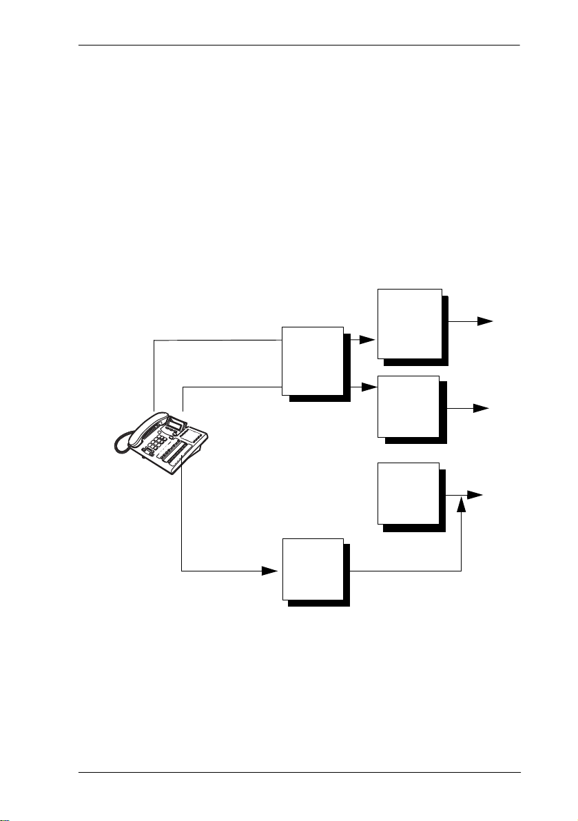
Networking features / 53
To restrict dialing within the system, you can apply restriction filters to:
• outgoing external lines (as line restrictions)
• telephones (as set restrictions)
• external lines on specific telephones (as line/set restrictions)
Restriction filters can also be specified in Restrictions service for times
when the system is operating according to a schedule. Refer to the
description in Services on page 174 for more details.
Calling out
Line restriction
no long
line 1
line 3
Set restriction
no long
distance
except
area codes
212, 718
distance
except
codes 212,
718, 214,
713
no long
distance
line 1
line 3
line 5
Line per set
no long
distance
restriction
no long
line 5
distance
except area
codes 212,
718, 415
Dialed digits must pass both the line restrictions and the set restrictions.
The line per set (line/set) restriction overrides the line restriction and set
restriction.
In this diagram, a caller using line 001 could only dial long-distance
numbers to area codes 212 and 718. A caller using line 003 could not dial
any long-distance numbers. A caller using line 005 could dial long-distance
numbers to area codes 212, 718, and 415.
P0603539 02 Compact ICS 6.1 Installer Guide
Page 54

54 / Networking features
Tip -
To restrict dialing from outside the system (once
a caller gains remote access), apply restriction filters to
incoming external lines (as remote restrictions).
Calling in
Line restriction
Remote
caller
Remote restriction
no long
distance
except area
codes 212,
718
Line pool
access
code 81
no long
distance
except area
codes 212,
718, 416
no long
distance
except area
codes 212,
718, 416
Line 1
Line 3
In this case, dialed digits must pass both the remote restriction and the line
restriction. A remote caller can override these filters by dialing the
DISA DN and entering a COS password.
For restriction filter programming instructions, see Restrn filters on page
170 in this guide.
Direct inward system access (DISA)
To control access from the public network, configure auto-answer trunks
to answer with DISA. Remote callers hear a stuttered dial tone and must
then enter a COS password that determines what they are allowed to do in
the system.
Auto-answer loop start trunks are configured to answer with DISA by
default. For DISA programming instructions, see Trunk/Line data under
Lines on page 161 in this guide.
Compact ICS 6.1 Installer Guide P0603539 02
Page 55

Networking features / 55
Transparent dialing plan
The Norstar system has a routing feature that allows you to set up a
transparent or coordinated dialing plan with other systems in the public
network. The goal is to have a network-wide dialing plan where all
telephone numbers are unique and of a uniform length.
Dialing plans are typically used with a network of systems with a three to
seven-digit dialing access between them.
Any programming for routing should be carefully planned using the tables
supplied with the Programming Record. The settings for routing and
destination codes are fully explained under Routing service on page 179.
This section deals with applying the programming in network situations.
Dialing plan using public lines
The following illustrations show the Programming Record for a Toronto
system in a network of three offices: Toronto, Halifax and Vancouver.
Without routing, a Norstar user in Toronto would have to select a line pool
and dial 1-902-585-3027 to reach extension 27 in Halifax (902). By
creating a destination code of 30 and creating a route that uses the proper
line pool and DialOut, the user simply dials 3027. The same feature is
available for Vancouver (604).
In the DialOut, P stands for pause, a host system signaling option. Press
²à¡
to insert a 1.5-second pause in the dialing string. See the System
Coordinator Guide for information about other signals.
Routing Service (
Route #
(000-999)
100
101
102
103
P0603539 02 Compact ICS 6.1 Installer Guide
Services: Routing Service
DialOut (if required)
(max. 24 digits or characters)
1-P-902-585
1-P-902-585
1-P-604-645
1-P-604-645
)
Use Pool
A B C
A B C
A B C
A B C
A B C
Page 56

56 / Networking features
Note that, in this case, only the Normal schedule is being used.
Routing service (continued)
Dest code (Services: Routing service: Dest codes)
Service Schedule
Sched name
(max. 7 char.)
DestCode
(max. 12 digits)
30
31
32
33
Normal
Normal
Use route
(001-999)
000
100
000
101
000
102
000
103
Absorb
Length
All
0
All
0
All
0
All
0
Other schedules:
1st route
(001-999)
000
000
000
000
Absorb
Length
All
All
All
All
000
Absorb
Length
2nd route
(001-999)
000 All
000
000
3rd route
(001-999)
000
000
All
000
All All
000
All
Destination code numbering in a network
Because the system checks the initial digits of a call against the routing
tables, each type of internal or external call must begin with a unique
pattern of digits. The following table gives a sample plan for how initial
digits are assigned in a network of systems with three-digit intercom
numbers.
Absorb
Length
All
All
All
Leading Digits Use
221-253 Intercom calls
Tip -
When programming a button to dial a
Network number automatically (autodial), network
calls must be treated as external numbers, even though
they resemble internal extension numbers.
Routes generally define the path between the Norstar
system and another switch in the network, not other
individual telephones on that switch.
Compact ICS 6.1 Installer Guide P0603539 02
Page 57

Data Solutions
Examples of ISDN Scenarios
For information about various ISDN scenarios that may help you to decide
on the data solution that is best for you, refer to the following web site:
http://www.nortelnetworks.com/support and perform a Search for TIPS
under Advanced Search. When you receive the search results, click on the
link titled Norstar SRN and Technical Tips (secure documentation).
Access granted to Channel Partners only. (collection). You will need
your user name and access code.
If you do not have a user name and access code, the site provides
information about how to get access to this site.
ISDN applications
ISDN terminal equipment delivers a wide range of powerful business
applications:
Video conferencing and video telephony
Video conferencing offers instant visual and audio contact between distant
parties using either studio-based or desktop ISDN terminals.
Desktop conferencing
ISDN allows computer users in distant locations to share and edit any
image, data or text file on their own computer screens while they discuss
the information.
File transfer
The ISDN network allows you to transfer files containing data, text,
images, data, or audio clips, faster and cheaper than with a conventional
modem.
P0603539 02 Compact ICS 6.1 Installer Guide
Page 58

58 / Data Solutions
Telecommuting
Convenient retrieval, processing and storage of files is possible for the
employee working at home by using ISDN lines to give high-speed access
to information resources at the office.
Group 4 fax
ISDN fax applications save money by increasing both transmission speed
and the quality of resolution.
Remote LAN access
ISDN provides an affordable and fast means for employees at remote sites,
such as at home or in branch offices, to access local area networks (LANs).
Leased line backup
Essential backup for leased lines can be provided using ISDN as required,
rather than duplicating costly permanent leased lines.
LAN to LAN bridging
Local area network (LAN) bridge/routers allow flexible interconnection
between LANs using ISDN, with charges only incurred when information
is actually transmitted.
Internet and database access
The fast call set up and high bandwidth of ISDN are ideal for accessing
information services such as the Internet and databases.
Compact ICS 6.1 Installer Guide P0603539 02
Page 59

Planning the installation
Only qualified persons should service the system.
The installation and service of this unit is to be
performed only by service personnel having
appropriate training and experience necessary to be
aware of hazards to which they are exposed in
performing a task and of measures to minimize the
danger to themselves or others.
Planning checklist
Consult the table Installing the cartridges on page 75 to verify that you
have the proper Compact ICS 6.1 software cartridge configuration.
Verify that you have all the equipment and supplies you need to install
the system.
Determine the location for the Integrated Communication System
(ICS) hardware, telephones, and other equipment.
Select the template to be used in System Startup. See Startup
programming on page 136.
Plan and record system programming details in the Compact ICS 6.1
Programming Record.
Equipment and supplies
Optional configuration for programmable Auto Attendant prompts
Integrated Communication System (ICS)
Feature Cartridge
Trunk Cartridge(s) for the ICS (as required)
BRI Card(s) for the ICS (as required)
Norstar telephones
ISDN devices (for example, terminal equipment, data devices), as
required
P0603539 02 Compact ICS 6.1 Installer Guide
Page 60

60 / Planning the installation
Expansion Cartridge (8 port, for analog only systems)
Expansion Cartridge with Clocking (8 port, for systems using BRI)
Clocking Cartridge (for systems using BRI, no additional set ports)
distribution panel(s)
The ICS supports up to 24 Norstar telephones (30 telephones, for profile 2
ETSI configurations). You must install an Expansion Cartridge with
Clocking or a Clocking Cartridge to use BRI Cards.
Optional equipment
station auxiliary power supply (SAPS)
Busy Lamp Field (BLF)
central answering position (CAP) modules for T7324 telephones or
key interface modules (KIM) for T7316E telephones
analog terminal adapter (ATA)
uninterruptible power supply (UPS)
analog emergency telephone
Digital Network Adapter
other
Equipment for installing the ICS
screwdriver
pliers
connecting tool
two 19 mm (3/4 in.) wood screws for the mounting bracket
one 32 mm (1-1/4 in.) wood screw for the bottom mounting tab
19 mm (3/4 in.) wood backboard (if necessary)
Compact ICS 6.1 Installer Guide P0603539 02
Page 61

Location requirements
clean, dry, and well-ventilated to allow free airflow
minimum clearance of 150 mm (5 in.) above and 100 mm (4 in.) below
the ICS
the gap between the ICS and the wall should be left completely clear
to allow proper heat dissipation
temperature between 0°C and 50°C (32°F and 122°F)
humidity between 5% and 95%, non-condensing
minimum distance of 4 m (13 ft) from equipment such as
photocopiers, electrical motors and other equipment that can produce
electromagnetic, radio-frequency, and electrostatic interference
Electrical requirements
non-switched, unobstructed outlet within 1.5 m (5 ft) of the ICS
dedicated 110 V - 120 V ac nominal, 50/60 Hz, 15 A minimum service
with a third wire safety ground to provide shock protection and avoid
electromagnetic interference
Planning the installation / 61
Risk of electric shock.
The safety of this product requires connection to an
outlet with a third-wire ground. Use only with threeprong power cord and outlet.
The ICS power cord is 1.5 m (5 ft) long. You may connect the ICS to
a power bar with a maximum length of two meters (6.5 ft), including
power bar. The power bar must be approved by an appropriate
National Test Body, with a third-wire ground. Do not use an extension
cord between the ICS and the power bar, or between the power bar and
the electrical outlet.
P0603539 02 Compact ICS 6.1 Installer Guide
Page 62

62 / Planning the installation
Internal wiring requirements
Norstar loop
one, two or three twisted-pair cable(s) per telephone
dc loop resistance of less than 64 Ω
cable length (0.5 mm or 24 AWG) less than 300 m (975 ft)
use of a station auxiliary power supply (SAPS) for loops 300 m (975
ft) to 1200 m (3900 ft). The SAPS must be a Class 2 power source that
is approved by an appropriate National Test Body.
no bridge taps
ISDN S reference point (S Loop)
no longer than 1000 m (3,200 ft) for point to point
no longer than 450 m (1,475 ft) on a point-to-multipoint extended
passive bus
no longer than 100 m (300 ft) for 75 ohm cable or 200 m (600 ft) for
150 ohm cable on a point-to-multipoint short passive bus
Wiring for the S reference point (S loop) should conform to ANSI T1.605.
Wiring for the ISDN U reference point (U loop) should conform to ANSI
T1.601.
Verify lightning protectors.
Check the lightning protectors at the cable entry point
to the building with special attention to the grounding.
Report any problems to the telephone company, in
writing.
Equipment that is designed to be connected using
internal wiring is typically not lightning protected.
Norstar telephone equipment and ISDN S loops and
T loops should not leave the building where the ICS is
installed.
Compact ICS 6.1 Installer Guide P0603539 02
Page 63

Spacing requirements
min.
150 mm (5 in)
238 mm
(9-3/8 in)
19 mm thick (3/4 in)
435 mm
(17-1/4 in)
min. 150 mm
(6 in.) between ICS
and cables
Planning the installation / 63
min. 100 mm (4 in)
between bottom and
floor or other object that
might block air flow
Mount well above the floor
to prevent water damage
P0603539 02 Compact ICS 6.1 Installer Guide
Power cord length 1.5 m (5 ft)
Page 64

64 / Planning the installation
Compact ICS 6.1 Installer Guide P0603539 02
Page 65

Upgrading your system
Only qualified persons should service the
system.
The installation and service of this unit is to be
performed only by service personnel having
appropriate training and experience necessary to
be aware of hazards to which they are exposed in
performing a task and of measures to minimize
the danger to themselves or other persons.
Electrical shock hazards from the
telecommunication network and AC mains are
possible with this equipment. To minimize risk to
service personnel and users, the ICS must be
connected to an outlet with a third-wire ground. In
addition, all unused slots must have filler
faceplates installed and the system cover must
be locked in place at the completion of any
servicing.
Service personnel must be alert to the possibility
of high leakage currents becoming available on
metal system surfaces during power line fault
events near network lines. Risk points on the ICS
are the Feature Cartridge, heatsink and power
cord earth ground pin. These leakage currents
normally safely flow to Protective Earth ground
via the power cord. Therefore, it is mandatory
that connection to an earthed outlet is performed
first and removed last when cabling to the unit.
Specifically, operations requiring the unit to be
powered down must have the network
connections (central office lines) removed first.
P0603539 02 Compact ICS 6.1 Installer Guide
Page 66

66 / Upgrading your system
When upgrading, Call Log information will be
lost.
When the system restarts, Call Log information is
not saved. Be sure to notify users if a system
restart is planned so any log information can be
written down first.
Upgrading a restricted Feature Cartridge
You can upgrade your restricted feature cartridge by entering a series of
Software Keys you obtain from Nortel Networks. This will add an
additional eight ports for Norstar telephones. Refer Software Keys on page
255 for more information.
Upgrading from 16 telephones to 24 telephones
The third slot in the ICS is used for an 8-port Expansion Cartridge, with or
without clocking. Installing a Clocking Cartridge (no expansion) does not
add additional Norstar telephone ports.
You cannot add the Expansion Cartridge to a system using a restricted
feature cartridge that has not been upgraded.
1. Verify your system programming and update the Programming
Record.
2. Disconnect all central office and station line connections from the ICS.
3. Remove power from your system.
4. Insert the Expansion Cartridge according to the Installation chapter.
Risk of fire and electrical shock.
For continued protection against risk of fire and electrical
shock, ensure all unpopulated cartridge slots are covered
by filler faceplates prior to powering up. Immediately after
powering up, connect the central office and station line
connectors and replace the cover.
5. Power up the system.
6. Connect the central office and station line connectors.
Compact ICS 6.1 Installer Guide P0603539 02
Page 67

Upgrading your system / 67
7. Replace the cover.
Removing an Expansion Cartridge cold starts
the system.
If you remove the Expansion Cartridge or
Expansion Cartridge with Clocking from the
Compact ICS, you will lose all the system
programming.
Upgrading to Compact ICS 6.1
When you upgrade from a previous Compact ICS version to 6.1:
1. Verify your system programming, and update the Programming
Record.
2. Disconnect all central office and station line connections from the ICS.
3. Remove power from your system.
4. Remove the Compact ICS Feature Cartridge.
5. Insert the Compact ICS 6.1 Feature Cartridge according to the
Installation chapter.
Risk of fire and electrical shock.
For continued protection against risk of fire and electrical
shock, ensure all unpopulated cartridge slots are covered
by filler faceplates prior to powering up. Immediately after
powering up, connect the central office and station line
connectors and replace the cover.
6. Power up the system.
7. Connect the central office and station line connectors.
8. Replace the cover.
P0603539 02 Compact ICS 6.1 Installer Guide
Page 68

68 / Upgrading your system
Upgrading Expansion Cartridge for BRI Card installation
The ICS must be equipped with an Expansion Cartridge with Clocking or
a Clocking Cartridge to support BRI Cards.
The Expansion Cartridge with Clocking adds eight telephone ports in
addition to clocking.
1. Disconnect all central office and station line connections from the ICS.
2. Remove power from your system.
3. Remove the Expansion Cartridge (without clocking).
4. Insert the Expansion Cartridge (with clocking) according to the
Installation chapter.
Risk of fire and electrical shock.
For continued protection against risk of fire and electrical
shock, ensure all unpopulated cartridge slots are covered
by filler faceplates prior to powering up. Immediately after
powering up, connect the central office and station line
connectors and replace the cover.
5. Power up the system.
6. Connect the central office and station line connectors.
7. Replace the cover.
Compact ICS 6.1 Installer Guide P0603539 02
Page 69

Installation
Only qualified persons should service the
system.
The installation and service of this unit is to be
performed only by service personnel having
appropriate training and experience necessary to
be aware of hazards to which they are exposed in
performing a task and of measures to minimize
the danger to themselves or other persons.
Electrical shock hazards from the
telecommunication network and AC mains are
possible with this equipment. To minimize risk to
service personnel and users, the ICS must be
connected to an outlet with a third-wire ground. In
addition, all unused slots must have filler
faceplates installed and the system cover must
be locked in place at the completion of any
servicing.
Service personnel must be alert to the possibility
of high leakage currents becoming available on
metal system surfaces during power line fault
events near network lines. Risk points on the ICS
are the Feature Cartridge, heatsink and power
cord earth ground pin. These leakage currents
normally safely flow to Protective Earth ground
via the power cord.
Therefore, it is mandatory that connection to an
earthed outlet is performed first and removed last
when cabling to the unit. Specifically, operations
requiring the unit to be powered down must have
the network connections (central office lines)
removed first.
P0603539 02 Compact ICS 6.1 Installer Guide
Page 70

70 / Installation
Installation checklist
test all ISDN network connections, if any
å
mount the Integrated Communications System (ICS)
å
install the Feature Cartridge
å
install the Trunk Cartridge and BRI Cards (as required)
å
install the appropriate expansion or clocking cartridge
å
Note: You must use the Expansion Cartridge with Clocking or Clocking
Cartridge to support BRI Cards
complete the wiring, but do not connect the central office and station
å
line connectors
install filler faceplates (slot covers)
å
install the emergency telephone(s), if required
å
install the Norstar telephones
å
install ISDN terminal equipment (TE)
å
install the other optional equipment
å
install the analog telephone(s)
å
power up the system
å
connect the central office and station line connectors
å
install the cover
å
Compact ICS 6.1 Installer Guide P0603539 02
Page 71

Installation / 71
Avoid electrical shock.
To avoid electrical shock hazard to personnel, or
equipment damage, observe the following precautions
when installing telephone equipment:
Always disconnect telecommunication network
connections before disconnecting the AC power plug.
Never connect the central office and station line
connectors until you have connected the power plug.
Never install telephone wiring during a lightning storm.
Never install telephone jacks in wet locations unless the
jack is specifically designed for wet locations.
Never touch non-insulated telephone wires or terminals
unless the telephone line has been disconnected at the
network interface.
Use caution when modifying or installing telephone lines.
Do not fasten power supply cords.
To comply with UL1459, do not fasten the ICS
power supply cord to any building surface,
including the backboard.
P0603539 02 Compact ICS 6.1 Installer Guide
Page 72

72 / Testing the ISDN network connection
Testing the ISDN network connection
Before you install a Norstar system which uses BRI Cards, you should test
your connection to the ISDN network.
If you are installing a system which connects to the network using BRI-ST
Cards, the network connection must be equipped with an NT1. See the
ISDN chapter and the wiring information in this chapter for more
information about installing an NT1.
To test the ISDN connection:
1. Connect ISDN terminal equipment (TE) that conforms to Bellcore
standards to your central office ISDN jack or NT1. U interface TE can
connect directly to the central office jack; S interface TE connect to the
central office through an NT1.
2. Program the TE with the appropriate switch type, service profile
identifier (SPID), and Network directory number (DN) using the
instructions that come with the TE.
3. Check for dial tone, then place a call and verify the quality and clarity
of the connection. If there is a problem, contact your service provider.
4. Repeat steps 1 through 3 for each network connection.
Compact ICS 6.1 Installer Guide P0603539 02
Page 73

Mounting the ICS
Mounting the ICS / 73
P0603539 02 Compact ICS 6.1 Installer Guide
Page 74

74 / Mounting the ICS
Attach bracket to secure surface.
Screw the ICS mounting bracket and ICS to a 19mm
wood backboard secured to a wall and capable of
supporting a 20 kg (44 lbs) mass. Do not screw bracket
directly to drywall. Use the two inner screw holes on
the bracket.
Compact ICS 6.1 Installer Guide P0603539 02
Page 75

Installing the cartridges / 75
Installing the cartridges
The following table shows which cartridges can be installed in the ICS
slots.
Cartridge type ICS slot
CICS 6.1 Restricted software (4 X 8) Feature Cartridge Slot
CICS 6.1 Standard software (16 X 24) Feature Cartridge Slot
CICS 6.1 Restricted software (I-RAD enabled) Feature Cartridge Slot
CICS 6.1 Standard software (I-RAD enabled) Feature Cartridge Slot
CICS 6.1 Standard software (I-RAD enabled)
Auto Attendant with programmable prompts
Expansion Cartridge (8 ports) 3
Expansion Cartridge (8 ports) with Clocking 3
Clocking Cartridge 3
Global Analog Trunk Cartridge (GATC) with LS/DS
replaces
Loop Start/Disconnect Supervision (LS/DS)
Analog Trunk Cartridge (supported on existing
systems, only)
Global Analog Trunk Cartridge (GATC) with CLID
replaces
Caller Identification (CI) Trunk Cartridge (supported
on existing systems, only)
BRI-ST Card 1 or 2
BRI-U2 Card 1 or 2
BRI-U4 Card 1 or 2
Feature Cartridge Slot
1 or 2
1 or 2
GATC with LS/DS and GATC with CLID ( LS/DS Analog Trunk
Cartridges and Caller Identification) Trunk Cartridges support loop start
external lines.
P0603539 02 Compact ICS 6.1 Installer Guide
Page 76

76 / Installing the cartridges
A system equipped with a restricted feature cartridge supports only the
BRI-U2 Card. It cannot support BRI-U4 or BRI-ST Cards.
PCB is electrostatic-sensitive.
Do not touch the printed circuit board on a
cartridge. This is an electrostatic-sensitive
device.
Close clips simultaneously.
It is important to center the cartridge and to close
the two clips on the cartridge simultaneously, or
the cartridge may become misaligned in its slot,
or with its connector.
Compact ICS 6.1 Installer Guide P0603539 02
Page 77

ICS slots and connectors
Power
light
Feature
Cartridge
Slot 1
Slot 2
Installing the cartridges / 77
Serial port
(for use with
future capabilties)
Slot 3
50-pin
connector 2
50-pin
connector 1
Removing the cover
To remove the cover, insert a screwdriver at the tab on the right side of the
ICS. Pry the latch open.
P0603539 02 Compact ICS 6.1 Installer Guide
Page 78

78 / Installing the cartridges
Installing the Feature Cartridge
SP 2.0
Insert Feature Cartridge one way.
To ensure the connector is properly installed,
insert the Feature Cartridge so that the connector
is properly aligned in the interior slot and the
version label is visible after installation.
Compact ICS 6.1 Installer Guide P0603539 02
Page 79

Installing the cartridges / 79
Terminating resistors on BRI-ST Cards
The standard ISDN user-network interface wiring requires terminating
resistors at each end of the loop for both point-to-point and point-tomultipoint operation. This ensures correct timing of the signaling circuits.
Loop termination can be provided at either the point where the ISDN
terminal is attached, or by the device attached to the loop (with built-in
termination).
Because the Compact ICS is usually at the one end of the loop, the BRI-ST
Card is shipped with built-in termination for each ISDN loop. It is ready to
be used where the ICS is located at one end of the loop, as shown in the
following illustration:
ICS
built-in termination
installed
TE connections without termination
TE with
termination
P0603539 02 Compact ICS 6.1 Installer Guide
Page 80

80 / Installing the cartridges
Shorting straps on a BRI-ST Card
termination
J8
J7
J6
installed
termination
removed
no shorting
strap
Make sure the shorting straps are installed on both the receive and transmit
jumpers for the loop (see illustration). The jumpers are numbered top to
bottom, but the loops associated with each pair of jumpers does not follow
the same top-to-bottom sequence (see table below).
Loop RX and TX shorting straps
1 J3 and J4
2 J7 and J8
3 J1 and J2
4 J5 and J6
Compact ICS 6.1 Installer Guide P0603539 02
Page 81

Installing the cartridges / 81
Installing Trunk Cartridges
1. Slide the Trunk Cartridge into slot 1, applying equal pressure at the top
and bottom. See illustration on the next page.
2. Close the cartridge clips at the same time, to keep the cartridge aligned
with the connector.
3. If you are installing a second trunk cartridge, remove the filler
faceplate from slot 2 and slot 3 (it is one piece), using a screwdriver at
the bottom of each slot and prying the bottom edge out.
4. Snap the two parts of the faceplate apart and put back the filler
faceplate in slot 3.
5. Insert the second Trunk Cartridge, as described in steps 2 and 3.
Global Analog Trunk Cartridge/CLI Cartridge
These cartridges have dip switches that may need to be set if your system
is not running with the North American profile (Profile 1). Set the dip
switches before you install the cartridge.
GATC dip switch settings (default is North America)(
The following table lists the various dip switch settings.
However, for this release, only the North America, Taiwan,
and Australia settings are active.
DIP switch setting Country profile
00000000 North America
10000000 Taiwan
01000000 Australia
11000000 *Chili
00100000 *Peru
10100000 *Argentina
01100000 *Mexico
P0603539 02 Compact ICS 6.1 Installer Guide
Page 82

82 / Installing the cartridges
DIP switch setting Country profile
11100000 *Sweden
00010000 *South America
10010000 *Brazil
01010000 *Norway
11010000 *France
00110000 *Germany
10110000 *Korea
XXXXXXX1 *Reserved
XXXXXX1X *Reserved
XXXXX1XX *Reserved
* Reserved for future development
Compact ICS 6.1 Installer Guide P0603539 02
Page 83

Installing the cartridges / 83
P0603539 02 Compact ICS 6.1 Installer Guide
Page 84

84 / Installing the cartridges
Installing the Expansion Cartridge
The Expansion Cartridge must be equipped with clock control if you are
installing BRI Cards.
1. Remove the filler faceplate from slot 3 (and slot 2 if there is no Trunk
Cartridge), using a screwdriver to pry the bottom edge(s) out.
2. If required, snap the two parts of the faceplate apart and put back the
filler faceplate in slot 2.
3. Slide the Expansion Cartridge into slot 3, applying equal pressure at
the top and bottom. See illustration on page 86.
4. Close the cartridge clips at the same time, to keep the cartridge aligned
with the connector.
Expansion Cartridge Expansion Cartridge
Compact ICS 6.1 Installer Guide P0603539 02
with Clocking
Clocking Cartridge
Page 85

Installing the cartridges / 85
Removing the expansion cartridge will cause
a cold restart.
If you downsize the system by removing the
expansion cartridge, all system programming will
be lost.
Alarm Telephone will indicate a cold reset.
An alarm and a prompt indicating warm or cold
reset will occur on the alarm telephone when the
system size has been decreased.
P0603539 02 Compact ICS 6.1 Installer Guide
Page 86

86 / Installing the cartridges
Installing the Expansion Cartridge
Compact ICS 6.1 Installer Guide P0603539 02
Page 87

Connecting the wiring / 87
Connecting the wiring
Connecting the wiring for a Compact ICS
Extend 150 mm (6 in.)
and clamp before bringing
cables together.
Do not attach central office
or station line connections until
power is connected to the ICS.
P0603539 02 Compact ICS 6.1 Installer Guide
Page 88

88 / Connecting the wiring
Connecting the wiring to the distribution panel
1. Route the cables from the ICS to the distribution panel.
2. Bundle the cables with cable ties and secure them to the wall to support
their weight.
3. Connect the telephone and auxiliary equipment wires to the
appropriate pins on the distribution block (refer to the wiring charts).
4. Cross-connect the ICS telephone and auxiliary equipment wiring to
the corresponding station pins on the distribution block.
5. Using a single pair of wires for each telephone, connect each of the
telephones according to the wiring charts.
6. Cross-connect the external lines to the distribution block (refer to the
wiring charts).
Wiring charts
Port numbering on the wiring charts
The port number listed on the wiring charts is useful in tracking down
faults during a Maintenance session where error codes appear on a Norstar
telephone display. Refer to Maintenance on page 305 for more
information.
For example, the code 112 appearing as part of an error message indicates
that the problem is with the telephone connected to the system at port 112.
The corresponding pins on the distribution block are pin 37 (black-orange)
and pin 12 (orange-black).
Integrated Communications System (ICS)
In the charts on the following pages, notice that the ICS has two 25-pair
connectors. One handles telephones and auxiliary ringer. The other handles
lines, I-ATA, music, and page.
Compact ICS 6.1 Installer Guide P0603539 02
Page 89

Connecting the wiring / 89
B1 and B2 directory numbers (DNs)
Norstar has a B1 and B2 channel for transmitting voice and data. Each
telephone port on the ICS has a B1 DN and a B2 DN. Devices such as the
Business Series Terminals, and Norstar telephones use only the B1 DN.
Other devices may need both B1 and B2 channels, therefore, requiring B1
and B2 DNs.
Norstar Compact ICS uses different numbering schemes for the B1 and B2
DNs, depending on how you upgrade your system and when an Expansion
Cartridge is added. See the tables below for details.
ICS numbering (restricted feature cartridge)
Connector #Device Ports B1 DN B2 DN
ICS (#1) Telephones 1-8
I-ATA
I-RAD
ICS (#2) Lines 001-004 201-204 — — — —
101-108
117
118
21-28
29 (I-ATA)
30 (I-RAD)
31-38
39
40
ICS numbering (restricted feature cartridge, expanded)
Connector #Device Ports B1 DN B2 DN
ICS (#1) Telephones 1-8
I-ATA
I-RAD
Telephones 9-16
ICS (#2) Analog:
Lines 001-004
Lines 031-034
BRI:
Lines 001-008
Lines 031-038
101-108
117
118
109-116
201-204
231-234
201-208
225-232
(Profile 1, 3, 4)
231-238
(Profile 2)
21-28
29 (I-ATA)
30 (I-RAD)
41-48
— —
— —
— —
— —
31-38
39
40
49-56
— —
— —
— —
— —
P0603539 02 Compact ICS 6.1 Installer Guide
Page 90

90 / Connecting the wiring
ICS numbering (restricted feature cartridge, expanded):
Expansion Cartridge added
Connector #Device Ports B1 DN B2 DN
ICS (#1) Telephones 1-8
I-ATA
I-RAD
Telephones 9-16
Telephones17-24
101-108
117
118
109-116
119-126
21-28
29 (I-ATA)
30 (I-RAD)
41-48
57-64
31-38
39
40
49-56
65-72
ICS numbering (standard feature cartridge)
Connector #Device Ports B1 DN B2 DN
ICS (#1) Telephones 1-16
I-ATA
I-RAD
101-116
117
118
21-36
37 (I-ATA)
38 (I-RAD)
39-54
55
56
ICS numbering (standard feature cartridge): Expansion
Cartridge added at installation
Connector #Device Ports B1 DN B2 DN
ICS (#1) Telephones 1-
16
I-ATA
I-RAD
Telephones
17-24
101-116
117
118
119-126
21-36
37 (I-ATA)
38 (I-RAD)
39-46
47-62
63
64
65-72
ICS numbering (standard feature cartridge): Expansion
Cartridge added later
Connector #Device Ports B1 DN B2 DN
Compact ICS 6.1 Installer Guide P0603539 02
Page 91

Connecting the wiring / 91
ICS (#1) Telephones 1-
16
I-ATA
I-RAD
Telephones 1724
Tip -
default numbering scheme.
I-ATA and I-RAD are not physically connected
to the ICS #1 25-pair connector.
The internal analog terminal adaptor (I-ATA) is
wired on the ICS #2 connector along with the
external lines and equipment for music and
paging. The internal remote access device
(I-RAD) appears on port 118 but has no wired
connection.
101-116
117
118
119-126
21-36
37 (I-ATA)
38 (I-RAD)
57-64
39-54
55
56
65-72
B1 and B2 directory numbers reflect the
ICS telephone and auxiliary ringer wiring chart
Pin Wire color Port Service Telephones (ICS)
26 White-Blue 101 T 1
1 Blue-White 101 R 1
27 White-Orange 102 T 2
2 Orange-White 102 R 2
28 White-Green 103 T 3
3 Green-White 103 R 3
29 White-Brown 104 T 4
4 Brown-White 104 R 4
30 White-Slate 105 T 5
5 Slate-White 105 R 5
31 Red-Blue 106 T 6
6 Blue-Red 106 R 6
P0603539 02 Compact ICS 6.1 Installer Guide
Page 92

92 / Connecting the wiring
Pin Wire color Port Service Telephones (ICS)
32 Red-Orange 107 T 7
7 Orange-Red 107 R 7
33 Red-Green 108 T 8
8 Green-Red 108 R 8
34 Red-Brown 109 T 9
9 Brown-Red 109 R 9
35 Red-Slate 110 T 10
10 Slate-Red 110 R 10
36 Black-Blue 111 T 11
11 Blue-Black 111 R 11
37 Black-Orange 112 T 12
12 Orange-Black 112 R 12
38 Black-Green 113 T 13
13 Green-Black 113 R 13
39 Black-Brown 114 T 14
14 Brown-Black 114 R 14
40 Black-Slate 115 T 15
15 Slate-Black 115 R 15
41 Yellow-Blue 116 T 16
16 Blue-Yellow 116 R 16
42 Yellow-Orange 119 T 17
17 Orange-Yellow 119 R 17
43 Yellow-Green 120 T 18
18 Green-Yellow 120 R 18
44 Yellow-Brown 121 T 19
19 Brown-Yellow 121 R 19
45 Yellow-Slate 122 T 20
20 Slate-Yellow 122 R 20
Compact ICS 6.1 Installer Guide P0603539 02
Page 93

Connecting the wiring / 93
Pin Wire color Port Service Telephones (ICS)
46 Violet-Blue 123 T 21
21 Blue-Violet 123 R 21
47 Violet-Orange 124 T 22
22 Orange-Violet 124 R 22
48 Violet-Green 125 T 23
23 Green-Violet 125 R 23
49 Violet-Brown 126 T 24
24 Brown-Violet 126 R 24
50 Violet-Slate ---- Make Aux. ringer
25 Slate-Violet ---- Common Aux. ringer
T and R represent station connections and should not be confused with Tip and
Ring on external lines. Station connections are non-polarized.
Stations 18 through 25 are available only when an Expansion Cartridge is installed.
For default DNs, see the ICS numbering charts starting on page 89.
Note: Central Answering Positions (CAP) that require a station auxiliary power
supply (SAPS) must be connected with a four-wire cord, as the SAPS is connected to the second wire pair. This includes any T7324 and CAP module combination, and any T7316E telephone attached to more than 4 KIMs. Refer to the
SAPS installation card for detailed installation instructions.
Wiring arrangement for Norstar ICS
15.2 m
(50 ft.)
max.
ICS
external line
connections,
auxiliary
services,
I-ATA and
emergency
telephone
two 25-pair connectors
P0603539 02 Compact ICS 6.1 Installer Guide
length
Distribution block
auxiliary
services
emergency telephone
I-ATA
external
lines
RJ-21/CA-21
Page 94

94 / Connecting the wiring
ICS external lines, I-ATA, music, and page wiring
ICS external lines connector
Pin Wire color Port Service Equipment
26 White-Blue 201 T Line 1
1 Blue-White 201 R Line 1
27 White-Orange 202 T Line 2
2 Orange-White 202 R Line 2
28 White-Green ---- ---- ----
3 Green-White ---- ---- ----
29 White-Brown ---- ---- ----
4 Brown-White ---- ---- ----
30 White-Slate 203 T Line 3
5 Slate-White 203 R Line 3
31 Red-Blue 204 T Line 4
6 Blue-Red 204 R Line 4
32 Red-Orange ---- ---- ----
7 Orange-Red ---- ---- ----
33 Red-Green ---- ---- ----
8 Green-Red ---- ---- ----
34 Red-Brown 231 T Line 31
9 Brown-Red 231 R Line 31
35 Red-Slate 232 T Line 32
10 Slate-Red 232 R Line 32
36 Black-Blue ---- ---- ----
11 Blue-Black ---- ---- ----
37 Black-Orange ---- ---- ----
12 Orange-Black ---- ---- ----
38 Black-Green 233 T Line 33
13 Green-Black 233 R Line 33
39 Black-Brown 234 T Line 34
14 Brown-Black 234 R Line 34
40 Black-Slate ---- ---- ----
15 Slate-Black ---- ---- ----
Compact ICS 6.1 Installer Guide P0603539 02
Page 95

Connecting the wiring / 95
ICS external lines connector
Pin Wire color Port Service Equipment
41 Yellow-Blue ---- ---- ----
16 Blue-Yellow ---- ---- ----
42 Yellow-Orange ---- T emergency telephone
17 Orange-Yellow ---- R emergency telephone
43 Yellow-Green ---- ---- ----
18 Green-Yellow ---- ---- ----
44 Yellow-Brown ---- ---- ----
19 Brown-Yellow ---- ---- ----
45 Yellow-Slate 117 T I-ATA
20 Slate-Yellow 117 R I-ATA
46 Violet-Blue ---- ---- ----
21 Blue-Violet ---- ---- ----
47 Violet-Orange ---- ---- ----
22 Orange-Violet ---- ---- ----
48 Violet-Green ---- Ground Music
23 Green-Violet ---- Music Music
49 Violet-Brown ---- Make External Page
24 Brown-Violet ---- Common External Page
50 Violet-Slate ---- T Page
25 Slate-Violet ---- R Page
Lines 5 through 8 are not available to a system using a restricted feature cartridge that has not been upgraded. For an explanation of port numbering, see
Port numbering on the wiring charts
line 002 (on Trunk Cartridge in slot 1).
on page 88. The emergency telephone uses
Music source must be grounded.
To avoid possible damage to your Compact ICS
system or music source, the music source
ground must be connected according to the
wiring charts.
P0603539 02 Compact ICS 6.1 Installer Guide
Page 96

96 / Connecting the wiring
BRI Wiring charts
A BRI Card in Slot 1 uses loops 201 through 204. A BRI Card in Slot 2
uses loops 225 through 228 (profile 1, 3 or 4) or loops 231 through 234
(profile 2). Because a BRI-U2 Card has only two loops, it only uses the first
two loop numbers (201-202 and 225-226 (profile 1, 3, or 4) or 231-232
(profile 2)) when it occupies an ICS slot.
The loops appearing on a BRI Card may be automatically assigned lines,
or assigned one or more ISDN DNs in
Hardware
is configured as S or T or NT, lines are automatically assigned. If the loop
is configured as S or LT, you can assign one or more ISDN DNs to the loop.
The emergency telephone connection (pins 42 and 17 on ICS #2 connector)
cannot be used if a BRI Card is installed in Slot 1. All other pins which are
not shown in the BRI wiring charts are assigned as shown in the non-BRI
wiring charts beginning on page 91.
Detailed information about configuring BRI Cards is included in the ISDN
chapter and in the Hardware section of the Programming chapter.
ST Interface Cards wiring chart (profile 1, 3 or 4)
programming. If the loop
Pin Wire color Loop Service Lines
(S or T loop)
26 White-Blue 201 +Tx Lines 001-002 Assigned DN
1 Blue-White 201 -Tx Lines 001-002 Assigned DN
27 White-Orange 201 +Rx Lines 001-002 Assigned DN
2 Orange-White 201 -Rx Lines 001-002 Assigned DN
28 White-Green 202 +Tx Lines 003-004 Assigned DN
3 Green-White 202 -Tx Lines 003-004 Assigned DN
29 White-Brown 202 +Rx Lines 003-004 Assigned DN
4 Brown-White 202 -Rx Lines 003-004 Assigned DN
30 White-Slate 203 +Tx Lines 005-006 Assigned DN
5 Slate-White 203 -Tx Lines 005-006 Assigned DN
31 Red-Blue 203 +Rx Lines 005-006 Assigned DN
6 Blue-Red 203 -Rx Lines 005-006 Assigned DN
Compact ICS 6.1 Installer Guide P0603539 02
Terminal
equipment
(S loop)
Page 97

Connecting the wiring / 97
Pin Wire color Loop Service Lines
(S or T loop)
Terminal
equipment
(S loop)
32 Red-Orange 204 +Tx Lines 007-008 Assigned DN
7 Orange-Red 204 -Tx Lines 007-008 Assigned DN
33 Red-Green 204 +Rx Lines 007-008 Assigned DN
8 Green-Red 204 -Rx Lines 007-008 Assigned DN
34 Red-Brown 225 +Tx Lines 031-032 Assigned DN
9 Brown-Red 225 -Tx Lines 031-032 Assigned DN
35 Red-Slate 225 +Rx Lines 031-032 Assigned DN
10 Slate-Red 225 -Rx Lines 031-032 Assigned DN
36 Black-Blue 226 +Tx Lines 033-034 Assigned DN
11 Blue-Black 226 -Tx Lines 033-034 Assigned DN
37 Black-Orange 226 +Rx Lines 033-034 Assigned DN
12 Orange-Black 226 -Rx Lines 033-034 Assigned DN
38 Black-Green 227 +Tx Lines 035-036 Assigned DN
13 Green-Black 227 -Tx Lines 035-036 Assigned DN
39 Black-Brown 227 +Rx Lines 035-036 Assigned DN
14 Brown-Black 227 -Rx Lines 035-036 Assigned DN
40 Black-Slate 228 +Tx Lines 037-038 Assigned DN
15 Slate-Black 228 -Tx Lines 037-038 Assigned DN
41 Yellow-Blue 228 +Rx Lines 037-038 Assigned DN
16 Blue-Yellow 228 -Rx Lines 037-038 Assigned DN
BRI ST wiring is polarity sensitive.
Tx and Rx are Transmit and Receive for Norstar.
P0603539 02 Compact ICS 6.1 Installer Guide
Page 98

98 / Connecting the wiring
ST Interface Cards wiring chart (profile 2)
Pin Wire color Loop Service Lines
(S or T loop)
Terminal
equipment
(S loop)
26 White-Blue 201 +Tx Lines 001-002 Assigned DN
1 Blue-White 201 -Tx Lines 001-002 Assigned DN
27 White-Orange 201 +Rx Lines 001-002 Assigned DN
2 Orange-White 201 -Rx Lines 001-002 Assigned DN
28 White-Green 202 +Tx Lines 003-004 Assigned DN
3 Green-White 202 -Tx Lines 003-004 Assigned DN
29 White-Brown 202 +Rx Lines 003-004 Assigned DN
4 Brown-White 202 -Rx Lines 003-004 Assigned DN
30 White-Slate 203 +Tx Lines 005-006 Assigned DN
5 Slate-White 203 -Tx Lines 005-006 Assigned DN
31 Red-Blue 203 +Rx Lines 005-006 Assigned DN
6 Blue-Red 203 -Rx Lines 005-006 Assigned DN
32 Red-Orange 204 +Tx Lines 007-008 Assigned DN
7 Orange-Red 204 -Tx Lines 007-008 Assigned DN
33 Red-Green 204 +Rx Lines 007-008 Assigned DN
8 Green-Red 204 -Rx Lines 007-008 Assigned DN
34 Red-Brown 231 +Tx Lines 031-032 Assigned DN
9 Brown-Red 231 -Tx Lines 031-032 Assigned DN
35 Red-Slate 231 +Rx Lines 031-032 Assigned DN
10 Slate-Red 231 -Rx Lines 031-032 Assigned DN
36 Black-Blue 232 +Tx Lines 033-034 Assigned DN
11 Blue-Black 232 -Tx Lines 033-034 Assigned DN
37 Black-Orange 232 +Rx Lines 033-034 Assigned DN
12 Orange-Black 232 -Rx Lines 033-034 Assigned DN
38 Black-Green 233 +Tx Lines 035-036 Assigned DN
13 Green-Black 233 -Tx Lines 035-036 Assigned DN
39 Black-Brown 233 +Rx Lines 035-036 Assigned DN
14 Brown-Black 233 -Rx Lines 035-036 Assigned DN
40 Black-Slate 234 +Tx Lines 037-038 Assigned DN
15 Slate-Black 234 -Tx Lines 037-038 Assigned DN
Compact ICS 6.1 Installer Guide P0603539 02
Page 99

Connecting the wiring / 99
Pin Wire color Loop Service Lines
(S or T loop)
41 Yellow-Blue 234 +Rx Lines 037-038 Assigned DN
16 Blue-Yellow 234 -Rx Lines 037-038 Assigned DN
Terminal
equipment
(S loop)
BRI ST wiring is polarity sensitive.
Tx and Rx are Transmit and Receive for Norstar.
Wiring the BRI network interface
A network interface provides the connection between the ISDN network
and the Compact ICS.
If the card in the ICS is configured as a T loop, the ICS is wired to the
network connection using an NT1. For an S or T loop, the ICS and terminal
equipment share the loop wired to the NT1, which is in turn wired to the
network. See the ISDN chapter for more information about the NT1.
Wiring for T or S network connection
Pin (jack or
plug)
1 not used optional power source 3 (+)
2 not used optional power source 3 (-)
3 +Rx +Tx
4 +Tx +Rx
5 -Tx -Rx
6 -Rx -Tx
7 not used optional power sink 2 (-)
8 not used optional power sink 2 (+)
NT1 connection (for
jack)
ICS and optional TE connection
(plug)
P0603539 02 Compact ICS 6.1 Installer Guide
Page 100

100 / Connecting the wiring
The Compact ICS supplies the NT1 functionality to a U-NT loop, allowing
a direct connection to the network. The connection may use a plug and
jack, or may be directly wired.
Wiring for U-NT network interface
Pin Norstar
connection
1 not used optional battery status indicator (+)
2 not used optional battery status indicator (-)
3 not used no connection
4 R R
5 T T
6 not used no connection
7 not used optional power supply (-)
8 not used optional power supply (+)
Network interface connection (plug/
jack)
The BRI-U Card does not use or provide optional power.
Some installations may not use a plug and jack for connections between the
ICS and the network.
The following illustration shows the pin arrangement for a Bellcore
standard ISDN plug and jack. Other pin arrangements are possible.
Pin numbering for network interface jack and plug
8 7 6 5 4 3 2 1
1 2 3 4 5 6 7 8
Compact ICS 6.1 Installer Guide P0603539 02
 Loading...