

Page 1

Call Center Management Information System
CCMIS
Release
CC MIS
Maintenance
5.2
Preliminary 297-2671-545.05.05
Maintenance Interface
User’s Guide
Page 2
CC MIS
NOTICE: Notwithstanding any explicit confidentiality or proprietary markings to the contrary, the
information contained in this document has been reviewed and approved for public disclosure
by Nortel. However, the access to, use and disclosure of this document and the information
contained therein continue to be subject to copyright and other restrictions, conditions and
limitations as detailed in the Terms of Use. (http://www.nortel.com/help/legal/index.html)
CC MIS Maintenance and Administration Guide
__________________________________
Maintenance Interface
CC MIS Release 5.2
NTP: 297-2671-545.05.05
Status: Preliminary
Date: January 2002
____________________________________
© 1991-2002 Nortel Networks Corporation
All rights reserved.
____________________________________
NORTEL NETWORKS CONFIDENTIAL:
The information contained in this document is the property of Nortel Networks (formerly Northern Telecom, Inc.).
Except as specifically authorized in writing by Nortel Networks, the holder of this document shall keep the
information contained herein confidential and shall protect same in whole or in
part from disclosure and dissemination to third parties and use same for evaluation, operation,
and maintenance purposes only.
Information is subject to change without notice. Nortel Networks reserves the right to make
changes in design or components as progress in engineering and manufacturing may warrant.
DMS and Meridian are trademarks of Nortel Networks. HP, HP RuggedWriter, and HP LaserJet are trademarks of
Hewlett-Packard Corporation. GRAFSMAN is a trademark of Soft-tek International. Reflection 4+ is a trademark
of Walker, Ritchie & Quinn, Inc. System V/88 and Veritas are trademarks of Motorola C orporation. Windo ws, Windows 95, and Windows NT are trademarks of the Microsoft Corporation.
Other trademarks, product names, and servicemarks contained in this guide are property of their respective
companies or owners.
European Regulatory Compliance and CE Marking:
The equipment is CE marked, identifying compliance with the relevant EU Directives, 89/336/EEC for
ElectroMagnetic Compatibility and 73/23/EECfor Safety.
This product is intended for deployment in a light industrial, non-domestic environment and complies with the
relevant EMC standards, EN55022 (class A) and EN50082-1. Since this is class A equipment, in a domestic
environment this equipment may cause radio interference in which case the user may be required to take adequate
measures.
Printed in the United States of America.
Page ii CC MIS Maintenance Guide
Page 3

Publication History
January 2002
Preliminary version for Testing Group and VO Sites Release 5.2.
CC MIS Maintenance Guide iii
Page 4

CC MIS
CC MIS
Publication History
Release 5.2
iv
297-2671-545
Page 5

Contents
About this Guide ...................................................................................intr-1
Acronyms ................................................................................................................intr-4
Terms ......................................................................................................................intr-5
Networked CC MIS ...............................................................................................1-1
Introduction ...........................................................................................1-1
Features Added in Release 4 .................................................................................1-3
Features Added in Release 5.0 ..............................................................................1-6
Features Added in Release 5.1 ..............................................................................1-6
Features Added in Release 5.2 ..............................................................................1-6
SNMP feature .........................................................................................................1-7
Operating System Configuration command .......................................................1-7
Required Database Information ...........................................................................1-8
Modes of Operation ...............................................................................................1-8
Introduction to Release 5 ......................................................................................2-1
Installing CC MIS Release 5 ................................................................2-1
Installing Release 5 ................................................................................................2-2
Configurable Intervals .......................................................................................2-9
CC MIS Maintenance Guide i
Page 6

CC MIS
CC MIS
Release 5.2
Contents
Installing Release 5 on New System .....................................................................2-10
New system ........................................................................................................2-10
Upgrade 3.x to 5.x ..................................................................................................2-11
Re-calculating data storage parameters ..............................................................2-11
Database upgrades .................................................................................................2-11
Preparing supervisor interface to CC MIS .........................................................2-11
Introduction to maintenance interface ................................................................3-1
Maintenance and administration menus ............................................................. 3-1
Selecting menu items .........................................................................................3-1
User interface screens ........................................................................................3-1
Accessing maint functions ....................................................................3-1
Accessing pop-up menus ...................................................................................3-2
Paging through a screen or menu .......................................................................3-2
Selecting a menu item ............................... ...... ...................................................3-2
Control commands .............................................................................................3-2
The role of the input/output line ........................................................................3-2
PF keys and commands .....................................................................................3-2
Menu map ...............................................................................................................3-3
Effect of the CC MIS operating state on the menu system ................................3-3
Setting up a new CC MIS system (overview) ......................................................3-4
Logging in ...............................................................................................................3-5
Constraints ......................................................................................................... 3-5
Guidelines .......................................................................................................... 3-6
Accessing on-line help ...........................................................................................3-7
Accessing help in menus ........................................................................................3-7
Accessing the help in screens ............................................................................3-8
Changing your password ......................................................................................3-9
Guidelines .......................................................................................................... 3-9
Logging out ............................................................................................................3-11
Guidelines .......................................................................................................... 3-11
Maintenance menus and screens ..........................................................................3-12
Maintenance and administration main menu .....................................................3-12
Configuration menu ...........................................................................................3-12
System upgrade utility menu .............................................................................3-13
Backup and restore menu ...................................................................................3-13
Run state utilities menu .....................................................................................3-14
Diagnostics menu ...............................................................................................3-14
Introduction ...........................................................................................................4-1
Shut down CC MIS ...............................................................................................4-1
Shutdown, Startup, and Power down .................................................4-1
Start up CC MIS ....................................................................................................4-2
Start up/shut down partitions .............................................................................4-2
Power down CC MIS ...................................... ...... ..... ........................................4-2
Shut down CC MIS ...............................................................................................4-2
Start up CC MIS ....................................................................................................4-4
Power down CC MIS .............................................................................................4-5
Power up the CC MIS system ...............................................................................4-6
Power failures ........................................................................................................ 4-7
CC MIS was not running ...................................................................................4-7
CC MIS was running .........................................................................................4-7
Introduction ...........................................................................................................5-1
CC MIS Maintenance Guide ii
Page 7

CC MIS
CC MIS
Release 5.2
Contents
Backing up and Restoring data ..........................................................5-1
Using the DAT drive for backups ........................................................................5-2
Write-protecting your DAT ...............................................................................5-3
Backing up customer data ....................................................................................5-4
Automatic backups ............................................................................................5-5
Manual backups .................................................................................................5-5
Backup screen commands ..................................................................................5-6
Constraints ......................................................................................................... 5-7
Guidelines .........................................................................................................5-8
Restoring customer data from tape .....................................................................5-9
Constraints ......................................................................................................... 5-9
Introduction ...........................................................................................................6-1
Configuring the CC MIS system ........................................................6-1
Accessing the Configuration main menu .............................................................6-2
Guidelines .......................................................................................................... 6-2
System Configuration ............................................................................................6-3
Guidelines .......................................................................................................... 6-4
Field descriptions ............................................................................................... 6-4
Port Allocation .......................................................................................................6-6
Constraints ......................................................................................................... 6-6
Guidelines .......................................................................................................... 6-7
Switch link configuration ......................................................................................6-8
Guidelines .......................................................................................................... 6-8
Command menu options ....................................................................................6-9
Live link .............................................................................................................6-9
Simulator link ....................................................................................................6-10
Terminal Server Configuration ............................................................................6-11
Guidelines .......................................................................................................... 6-11
Adding a Terminal Server .................................................................................6-12
Configuring a Terminal Server ..........................................................................6-12
Editing a field ....................................................................................................6-13
SNMP configuration ..............................................................................................6-14
Field descriptions ............................................................................................... 6-15
Guidelines .......................................................................................................... 6-16
System configuration reports ...............................................................................6-17
Introduction ...........................................................................................................7-1
Partitions (local) ....................................................................................7-1
Operating modes ................................................................................................7-2
Requirements for a running state .......................................................................7-3
Partition configuration commands .....................................................................7-3
Partition configuration options ..........................................................................7-4
Adding a Partition ..............................................................................................7-5
Guidelines .......................................................................................................... 7-5
Deleting a Partition ............. ..... ...... ....................................................................7-6
Partition options ....................................................................................................7-7
Guidelines .......................................................................................................... 7-12
Disk Allocation .......................................................................................................7-13
Guidelines .......................................................................................................... 7-14
Storage calculator ..................................................................................................7-16
Guidelines .......................................................................................................... 7-16
CC MIS Maintenance Guide iii
Page 8

CC MIS
CC MIS
Release 5.2
Contents
Changing data storage parameters ......................................................................7-17
Guidelines .......................................................................................................... 7-17
Interval Configuration ................ ...... ....................................................................7-18
Issues Concerning Interval Lengths ...................................................................7-18
Connection parameters .........................................................................................7-19
Guidelines .......................................................................................................... 7-20
Serial Terminals .....................................................................................................7-21
Add, Delete, or Change .....................................................................................7-21
Guidelines .......................................................................................................... 7-22
Printers ...................................................................................................................7-23
Constraints ......................................................................................................... 7-23
Guidelines .......................................................................................................... 7-24
Changing a printer definition ............................................................................... 7-25
Guidelines .......................................................................................................... 7-25
Removing a printer from the system ...................................................................7-26
Guidelines .......................................................................................................... 7-26
Wallboards ............................................................................................................. 7-27
Constraints ......................................................................................................... 7-27
Guidelines .......................................................................................................... 7-28
Changing a wallboard's configuration ...............................................................7-28
Removing a wallboard from the system ............................................................7-28
LAN Terminals ............................ .................................................................... ......7-29
Adding LAN Terminals .....................................................................................7-30
Deleting LAN Terminals .......................... ...... ...... .............................................7-30
Supervisor Privileges .................................... ...... ...................................................7-31
Guidelines .......................................................................................................... 7-31
Display privileges ..............................................................................................7-32
Report privileges ................................................................................................7-32
Configuration control privileges ........................................................................7-33
Supervisor privileges .........................................................................................7-34
Administration privileges ..................................................................................7-34
Data Access Priviledges ....................................................................................7-35
Supervisor override privileges ...........................................................................7-35
Partition Startup/Shutdown .................................................................................7-37
Guidelines .......................................................................................................... 7-38
Configuring a PC to receive data export files .....................................................7-39
Introduction to Networked CC MIS ................................................... ..... ............8-1
Networked CC MIS .............................................................................8-1
Overview of a Network .........................................................................................8-2
Views in the Network ............................................................................................8-2
Steps for Establishing a Network .........................................................................8-3
System Configuration ............................................................................................8-4
Guidelines .......................................................................................................... 8-5
Field descriptions ............................................................................................... 8-5
Physical Network Configuration ..........................................................................8-7
Adding a node to the physical network ...............................................................8-9
Deleting a node from the physical network .........................................................8-10
Switch Link Configuration ...................................................................................8-11
Partition Configuration .........................................................................................8-11
Guidelines .......................................................................................................... 8-15
Deleting a Partition ............. ..... ...... ....................................................................8-16
Partition configuration options ..........................................................................8-17
CC MIS Maintenance Guide iv
Page 9

CC MIS
CC MIS
Release 5.2
Contents
Disk Allocation .......................................................................................................8-18
Virtual Network Configuration ............................................................................8-19
Partition options .................................................................................................8-22
Guidelines .......................................................................................................... 8-25
Introduction ...........................................................................................................9-1
Monitoring system functions ...............................................................9-1
Accessing the diagnostics menu ........................................................................9-2
Displaying free disk space .....................................................................................9-3
File transfer ............................................................................................................9-4
Testing the input/output ports ..............................................................................9-6
Test individual I/O ports ......................................................................................9-7
Logs .........................................................................................................................9-8
Viewing a log ............................................................. ........................................9-10
Monitoring a log ................................................................................................9-11
Printing a log ......................................................................................................9-12
Cancelling the log printout ................................................................................9-12
View system monitor .............................................................................................9-13
Program status ........................................................... ...... ..................................9-13
Lock status .........................................................................................................9-17
Partition status ...................................................................................................9-19
Port status ....................................... ...... ..... .........................................................9-21
CPU utilization status ........................................................................................9-23
Additional System Monitor Screens .................................................................. 9-25
Physical Node Status .........................................................................................9-25
Virtual Node Status ............................................................................................9-25
Resetting the modem port ..................................................................................9-26
Link trace ...............................................................................................................9-27
Starting / Stopping the link trace .......................................................................9-30
Viewing the link trace ........................................................................................9-30
Viewing the translated link trace .......................................................................9-31
Using the Search function ..................................................................................9-31
Search Instructions .............................................................................................9-32
Printing the link trace .........................................................................................9-33
Printing the translated link trace ........................................................................9-33
Cancelling link trace printing ............................................................................9-34
Select different link ............................................................................................9-34
TCP / IP Switch Link Diagnostics ........................................................................9-36
Checking a switch link .......................................................................................9-36
X.25 Diagnostics .....................................................................................................9-37
Checking an X.25 link .......................................................................................9-37
Disabling an X.25 link .......................................................................................9-38
Enabling an X.25 link ........................................................................................9-38
Cancel X.25 link check .....................................................................................9-39
Initializing an X.25 link .....................................................................................9-39
Physical Network Login ........................................................................................9-40
Introduction ...........................................................................................................10-1
Configuration Updates ........................................................................10-1
Introduction ...........................................................................................................11-1
CC MIS software upgrades ...............................................................11-1
CC MIS Maintenance Guide v
Page 10

CC MIS
CC MIS
Release 5.2
Contents
Software upgrades .............................................................................................11-2
Load new software version ................................................................................... 11-2
.................................................................................................................................11-5
Installing a New Keycode on CC MIS 5.0 System ..............................................11-6
Introduction ...........................................................................................................12-1
SNMP transfer ......................................................................................12-1
Guidelines .......................................................................................................... 12-2
Changing OS configuration ..................................................................................13-1
Operating System Config ....................................................................13-1
Adding a Unix printer ........................................................................................13-2
Deleting a Unix printer ......................................................................................13-4
Adding disk(s) command ...................................................................................13-4
Changing Time Zone settings ............................................................................13-5
Making direct changes to the OS configuration ................................................13-6
Getting help .......................................................................................................13-7
Preventive maintenance ........................................................................................14-1
Check filter .......................................................................................................14-1
Preventive maintenance ......................................................................14-1
Tape rotation ......................................................................................................14-2
DAT head cleaning ............................................................................................14-2
Technical specifications ........................................................................A-1
Real-time performance ......................................................................................A-1
Reliability ..........................................................................................................A-1
Consistent configuration data ............................................................................A-1
Automatic backup ..............................................................................................A-2
Power failure .............................................................. ...... ..................................A-2
Personal computer support .................................................... ..... .......................A-2
System Log Messages ............................................................................B-1
Installing the operating system ............................................................C-1
Historical database ...............................................................................D-1
Historical database equations ...............................................................................D-4
Introduction ...........................................................................................................E-1
System Configuration Reports ............................................................E-1
System configuration report .................................................................................E-3
Port allocation report ............................................................................................E-4
Switch link configuration report ..........................................................................E-5
Partition configuration report ..............................................................................E-6
Disk allocation report ............................................................................................E-7
Connection parameters report .............................................................................E-8
Partition options report ........................................................................................E-9
Terminal server report ..........................................................................................E-10
StaticLAN terminal report ...................................................................................E-11
Serial terminal report ............................................................................................E-12
CC MIS Maintenance Guide vi
Page 11

CC MIS
CC MIS
Release 5.2
Contents
Printer configuration report .................................................................................E-13
Wallboard configuration report ...........................................................................E-14
Storage parameters report ....................................................................................E-15
Interval Configuration Report ............................................ ...... ...... .....................E-16
Simulator configuration report ............................................................................E-17
SNMP configuration report ..................................................................................E-18
Physical network configuration report ................................................................E-19
Virtual network configuration report ..................................................................E-20
Master privilege Override report .........................................................................E-21
Master privilege definition report ........................................................................ E-22
CC MIS Maintenance Guide vii
Page 12

CC MIS
CC MIS
Contents
Release 5.2
viii
297-2671-545
Page 13

Figures
Figure 3.1 Maintenance and Administration menus 3-3
Figure 3.2 Maintenance main menu (CC MIS operating) 3-5
Figure 3.3 Maintenance and Administration menu 3-12
Figure 3.4 Configuration menu 3-12
Figure 3.5 System upgrade utility menu 3-13
Figure 3.6 Backup and restore menu 3-13
Figure 3.7 Run state utilities menu 3-14
Figure 3.8 Diagnostics menu 3-14
Figure 4.1 Run state utilities menu 4-1
Figure 5.1 Backup and restore menu 5-1
Figure 5.2 DAT drive unit 5-2
Figure 5.3 Digital audio tape 5-3
Figure 5.4 Backup screen 5-6
Figure 5.5 Restore screen 5-10
Figure 6.1 Configuration main menu 6-2
Figure 6.2 System configuration screen 6-3
Figure 6.3 Port Allocation screen 6-6
Figure 6.4 Switch link configuration screen - Initial 6-8
CC MIS Maintenance Guide ix
Page 14

CC MIS
CC MIS
Release 5.2
Figures
Figure 6.5 Switch link configuration screen - live link 6-9
Figure 6.6 Switch link configuration screen - Simulator link 6-10
Figure 6.7 Terminal Server screen 6-11
Figure 6.8 Adding a Terminal Server 6-12
Figure 6.9 Configuring a Terminal Server 6-12
Figure 6.10 Editing a field on the Terminal Server screen 6-13
Figure 6.11 SNMP configuration 6-14
Figure 7.1 Configuration menu 7-1
Figure 7.2 Partition Configuration scr een 7-2
Figure 7.3 Partition options screen 7-7
Figure 7.4 Disk Allocation screen 7-13
Figure 7.5 Storage calculator screen 7-16
Figure 7.6 Interval Configuration screen 7-18
Figure 7.7 Connection Parameters screen 7-19
Figure 7.8 Serial terminals screen 7-21
Figure 7.9 Printer Configuration screen 7-23
Figure 7.10 Wallboard Configuration screen 7-27
Figure 7.11 LAN Terminals screen (with add text) 7-29
Figure 7.12 Master Privilege Definition screen 7-32
Figure 7.13 Display Privileges screen 7-32
Figure 7.14 Report Privileges screen 7-33
Figure 7.15 Configuration Control Privileges screen 7-33
Figure 7.16 Supervisor Privileges screen 7-34
Figure 7.17 Administration Privileges screen 7-34
Figure 7.18 Data Access Priviledge screen 7-35
Figure 7.19 Supervisor Override screen 7-35
Figure 7.20 Maintenance and Administration menu 7-37
Figure 7.21 Run state utilities screen 7-37
Figure 7.22 Partition startup and shutdown screen 7-38
Figure 8.1 Network Overview 8-2
Figure 8.2 Configuration menu 8-3
Figure 8.3 System Configuration screens 8-4
Figure 8.4 Physical Network Configuration screen 8-7
Figure 8.5 Add Node menu 8-9
Figure 8.6 Add Node Commands menu 8-9
Figure 8.7 Delete Node menu 8-10
Figure 8.8 Partition Configuration scr een 8-11
Figure 8.9 Add Partition op tions menu 8-13
Figure 8.10 Add Partition and Commands menus 8-14
Figure 8.11 Configuration Options menu 8-17
Figure 8.12 Virtual Network Configuration screen 8-19
Figure 8.13 Add Partition to Network screen 8-20
Figure 8.14 Delete Partition from Network screen 8-21
Figure 8.15 Delete Partition from Network confirmation screen 8-21
Figure 8.16 Partition options screen 8-22
Figure 9.1 Diagnostics menu (when software is running) 9-1
CC MIS Maintenance Guide x
Page 15

CC MIS
CC MIS
Release 5.2
Figures
Figure 9.2 Display Free Disk Space screen 9-3
Figure 9.3 File Transfer screen 9-4
Figure 9.4 Test individual I/O screen 9-7
Figure 9.5 CC MIS system logs screen 9-8
Figure 9.6 Program Status screen with Commands menu 9-13
Figure 9.7 Lock Status screen 9-17
Figure 9.8 Partition Status screen 9-19
Figure 9.9 Port Status screen 9-21
Figure 9.10 CPU Utilization Status screen 9-23
Figure 9.11 Physical Node Status screen 9-25
Figure 9.12 Virtual Node Status screen 9-25
Figure 9.13 Link Trace screen (multiple links) 9-27
Figure 9.14 CC MIS Link Trace menu screen 9-28
Figure 9.15 CC MIS Message Translator Filter screen 9-28
Figure 9.16 Untranslated Link Trace file example 9-29
Figure 9.17 Translated Link Trace file example 9-29
Figure 9.18 Search function key 9-31
Figure 9.19 Search screen 9-32
Figure 9.20 Search options pop-up 9-32
Figure 9.21 TCP / IP Switch Link Diagnostics 9-36
Figure 9.22 CC MIS X.25 Diagnostics screen (with Commands menu) 9-37
Figure 9.23 Physical Network Login screen 9-40
Figure 0.1 Run State Utilities menu 10-1
Figure 0.2 Configuration update prompt screen (multiple links) 10-2
Figure 0.3 Configuration update prompt screen (single link) 10-3
Figure 11.1 System Upgrade Utilities menu 11-1
Figure 11.2 Install License Keycode 11-6
Figure 11.3 System Serial Number 11-6
Figure 11.4 Entering Keycode 11-7
Figure 11.5 Confirm Settings 11-7
Figure 11.6 Continue Keycodes 11-8
Figure 12.2 Sample SNMP transfer session 12-2
Figure 3.2 OS Configuration menu 13-2
Figure 3.3 Adding a Unix printer 13-2
Figure 3.4 Specifying the name 13-3
Figure 3.5 Adding the printer 13-3
Figure 3.6 Delete printer screen 13-4
Figure 3.7 Adding disk(s) 13-4
Figure 3.8 Time Zone 13-5
Figure 3.9 Direct OS Configuration 13-6
Figure 3.10 Help screen 13-7
Figure 4.1 Location of filter 14-2
Figure 4.2 DAT drive unit 14-3
Figure E.1 Configuration menu E-1
Figure E.2 System configuration report E-3
Figure E.3 Port allocation report E-4
CC MIS Maintenance Guide xi
Page 16

CC MIS
CC MIS
Figures
Release 5.2
Figure E.4 Switch link configuration report E-5
Figure E.5 Partition configuration report E-6
Figure E.6 Disk allocation report E-7
Figure E.7 Connection parameters report E-8
Figure E.8 Partition options report E-9
Figure E.9 Terminal server report E-10
Figure E.10 Static LAN terminals report E-11
Figure E.11 Serial terminal report E-12
Figure E.12 Printer configuration report E-13
Figure E.13 Wallboard configuration report E-14
Figure E.14 Storage Parameters report E-15
Figure E.15 Interval configuration report E-16
Figure E.16 Simulator configuration report E-17
Figure E.17 SNMP configuration report E-18
Figure E.18 Physical network configuration report E-19
Figure E.19 Virtual network configuration report E-20
Figure E.20 Master Privilege Override report E-21
Figure E.21 Master Privilege Definition report E-22
xii
297-2671-545
Page 17

Tables
T ab le 1: T yp ograph ical conventions intr-2
Table 2: Conventions used in procedures intr-3
Table 2-1: Data storage parameters 2-3
Table 3-1: Functions requiring CC MIS to be shut down 3-4
Table 5-1: Backup screen commands 5-7
Table 6-1: System configuration field d escriptions 6-4
T a b le 6-2: SNMP field descriptions 6-15
Table 7-1: Par tition configuration function commands 7-3
Table 7-2: Partition configuration options 7-4
Table 7-3: Par tition options screen fields 7-8
Table 7-4: Disk allocation screen parameters 7-14
Table 7-5: Connection parameter screen fields 7-19
T able 7-6: Supervisor Override field descriptions 7-36
Table 8-1: System configuration field d escriptions 8-5
Table 8-2: Physical Network screen definitions 8-8
Table 8-3: Physical Networ k Function keys 8-8
Table 8-4: Add Node comm ands 8-10
Table 8-5: Func tion key commands 8-12
CC MIS Maintenance Guide xiii
Page 18

CC MIS
CC MIS
Tables
Release 5.2
Table 8-6: Add Partition commands menu 8-14
Table 8-7: Partition configuration options 8-18
Table 8-8: Virtual Network Configuration field descriptions 8-19
Table 8-9: Virtual Network Configuration function keys 8-20
Table 8-10: Partition options screen fields 8-2 3
Table 9-1: Logs screen fields 9-9
Table 9-2: Program status screen fields 9-14
T ab le 9-3: Lock status screen fields 9-17
Table 9-4: Par tition status screen fields 9-19
T ab le 9-5: Port status screen fields 9-21
Table 9-6: CPU Utilization status fields 9-23
Table D-1: Historical database tables D-1
Table D-2: Historical database values D-2
xiv
297-2671-545
Page 19

Steps
Step 2-1: Installing Release 5 on a new system 2-10
Step 2-2: Preparing PCs to display CC MIS 2-12
Step 3-1: Logging into maint 3-6
Step 3-2: Accessing on-line help in maintenance menus 3-7
Step 3-3: Accessing on-line help in user interface screens 3-8
Step 3-4:Changing the maint password 3-9
Step 3-5:Logging out of maint 3-11
Step 4-1: Shutting down CC MIS 4-3
Step 4-2: Starting CC MIS 4-4
Step 4-3: Power down CC MIS 4-5
Step 4-4: Powering up CC MIS 4-6
Step 4-5: Recovering from a power failure 4-7
Step 5-1: Accessing the backup and restore menu 5-2
Step 5-2: Inserting a DAT tape into the tape drive 5-4
Step 5-3: Ejecting a DAT tape from the tape drive 5-4
Step 5-4: Backing up customer data 5-8
Step 5-5: Restoring customer data 5-11
Step 6-1: Accessing the Configuration menu 6-2
Step 6-2: Accessing the System Configuration screen 6-4
Step 6-3: Accessing the Port Allocation screen 6-7
CC MIS Maintenance Guide xv
Page 20

CC MIS
CC MIS
Release 5.2
Steps
Step 6-4: Accessing the Switch Link Configuration screen 6-8
Step 6-5: Accessing the Terminal Server screen 6-11
Step 6-6: Accessing the SNMP Configuration screen 6-16
Step 7-1: Adding a partition 7-5
Step 7-2: Deleting a partition 7-6
Step 7-3: Accessing the Partition Options screen 7-12
Step 7-4: Assigning a disk 7-14
Step 7-5: Reviewing database parameters 7-16
Step 7-6: Changing data storage parameters 7-17
Step 7-7: Accessing the Connection Parameters screen 7-20
Step 7-8: Adding a serial terminal 7-22
Step 7-9: Adding a print er 7-24
Step 7-10:Changing a printer definition 7-25
Step 7-11:Removing a printer definition 7-26
Step 7-12:Adding a wallboard 7-28
Step 7-13: Accessing LAN terminals 7-29
Step 7-14: Adding LAN terminals 7-30
Step 7-15: Deleting LAN terminals 7-30
Step 7-16: Accessing the Master Privilege screen 7-31
Step 7-17:Accessing Partition Startup and Shutdown screen 7-38
Step 7-18: Setting up a PC to receive data export files 7-39
Step 8-1: Accessing the System Configuration screen 8-5
Step 8-2: Adding a NAP 8-15
Step 8-3: Deleting a partition 8-16
Step 8-4: Accessing the Partition Options screen 8-25
Step 9-1: Accessing the Diagnostic menu 9-2
Step 9-2: Displaying free disk space 9-3
Step 9-3: Performing a file transfer 9-5
Step 9-4: Testing all ports 9-6
Step 9-5: Testing an individual port 9-7
Step 9-6: Selecting a log 9-9
Step 9-7: Viewing a log 9-10
Step 9-8: Monitoring a log 9-11
Step 9-9: Printing a log 9-12
Step 9-10: Cancelling a log printout 9-12
Step 9-11: Accessing the View System Monitor screen 9-14
Step 9-12: Resetting a modem port 9-26
Step 9-13: Starting/stopping link trace 9-30
Step 9-14: Starting/stopping link trace 9-30
Step 9-15: Viewing a translated link trace file 9-31
Step 9-16: Printing a link trace file 9-33
Step 9-17: Printing a translated link trace file 9-34
Step 9-18: Cancelling link trace printing 9-34
Step 9-19: Selecting a different link for link trace 9-35
Step 9-20: Checking a TCP / IP link 9-36
Step 9-21: Checking an X.25 link 9-37
Step 9-22: Disabling an X.25 link 9-38
Step 9-23: Enabling an X.25 link 9-38
Step 9-24: Cancelling an X.25 link check 9-39
Step 9-25: Physical network login screen 9-40
Step 10-1: Accessing the configuration update screen 10-2
Step 10-2: Running a conf iguration update 10-3
Step 11-1: Load new CC MIS software version 11-3
Step 12-1: Accessing SNMP transfer screen 12-2
CC MIS Maintenance Guide xvi
Page 21

CC MIS
CC MIS
Release 5.2
Steps
Procedure C-1: Installing the SVR4 OS C-1
Procedure C-2: Installing the AIX OS C-6
C-8
CC MIS Maintenance Guide xvii
Page 22

CC MIS
CC MIS
Steps
Release 5.2
xviii
297-2671-545
Page 23
Release 5.2
r
t
r
About this Guide
CC MIS
CC MIS
Related
documents
This document is an operations guideline for the systems maintenance
engineer of a Call Center Management Information System
(CC MIS) linked to an MSL-100 (Meridian 1 Options 111-211),
DMS-500, or a DMS-100 supporting the 32 or 35 protocol version and
ACD-MIS Interface Specification, Version 6 and 9.
The switch supporting CC MIS, the MSL-100 o
Note:
Note:
The following Nortel Networks Publications (NTP) contain
additional information to supplement this document:
ACD MIS Interface Specifications, Version 9 (NT MIS-Q209-2)
DMS-100 Common Customer Data Schema (NTP 297-1001-451)
the DMS-100, is called a DMS-ACD throughou
this book.
It is recommended that your switch be at BCS35
when the Networking feature is enabled for you
CC MIS system.
CC MIS Maintenance Guide intr-1
MDC Customer Data Schema (NTP 297-2001-451)
Call Center MIS System Description (NTP 297-2671-150)
Meridian SL-100 AC D General Description (NT P 555-4101-100)
Meridian SL-100 AC D Load Management (NTP 555-4101-102)
Page 24
CC MIS
Release 5.2
Meridian SL-100 ACD Management Information Interface (NTP 555-4101-103)
Meridian SL-100 ACD Feature Operation and Testing (NTP 555-4101-300)
Meridian SL-100 ACD MMI and Feature Implementation (NTP 555-4101-310)
Meridian SL-100 Network ACD General Description (NTP 555-8101-100)
For more information on ACD, refer to the following Northern
Telecom Publications (NTPs):
ACD Product Guide (NTP 297-2041-010)
ACD Server Product G uid e (NTP 29 7-2 041-011)
ACD Planning and Engineering Guide (NTP 297-2041-101)
ACD Planning and Engineering Guide - Canada (NT P 297-2041-104)
ACD Administration Guide (NTP 297-2041-30 1)
ACD Translations (NTP 297-2041-350)
ACD Maintenance Guide (NTP 297-2041-500)
ACD Trouble Locating and Clearing Procedures (NTP 297-2041-503)
M5212 ACD Set General Description (NTP 297-2041-900)
ACD End-User Load Manag e ment (NTP 297-2041-901)
Network ACD General Descr iption (up to BCS 34) (NTP 555-8101-100)
The following typographic conventions are used throughout this
user guide.
Table 1: Typographical conventions
Key Sequence Function
<Return> Words in angled brackets represent a
specific key on your keyboard that you
should press.
[Commands] Words in square brackets represent one
of the keys available to you from the
function key menu.
intr-2 297-2671-545
Page 25
Release 5.2
ed
s.
of
to
to
CC MIS
CC MIS
The PF keys associated with a command are list
Note:
The following typographic conventions are used in the procedural
tables in this user guide.
Table 2: Conventions used in procedures
Key Sequence Function
Enter n Letters in italics represent the key that
on the lower portion of the appropriate screen.
Procedures in this guide provide the name of
the function key. The screens in this guide show
examples of PF keys with associated command
The actual PF number is dependent on the type
terminal and emulation mode being used. Refer
the program screen for the actual function key
press to select the desired command.
you press in the action part of the
procedure. Enter means that you press
<Return> after you press the key.
Notice Words in italics represent a system re-
sponse to the actions in the procedure.
Did you Words in bold represent the text of a
specific message on a screen.
CC MIS Maintenance Guide intr-3
Page 26

CC MIS
Release 5.2
Acronyms
This document uses the following acronyms:
Acronym Meaning
ACD Automatic Call Distribution
CC MIS Call Center MIS
DAT Digital Audio Tape
DB Database
LAN Local Area Network
LOB Line-of-Business
MAR Message Arrival Rate
MIB Management Information Base
MIS Management Information System
MSR Message Service Rate
NAP Network Access Partition
NMS Network Manage ment Syste m
NOS Network Operation Services
PC Personal Computer
SNMP Simple Network Management Prot oco l
intr-4 297-2671-545
Page 27

Release 5.2
CC MIS
CC MIS
Terms
This document uses the following terms:
direct connect printer A printer that is physically connected to the host
machine.
local partition A partition that provides access to local data
only.
NAP Network Access Partition. A partitio n that p ro-
vides access to other partitions in the network.
NAPs can only exist on a network node.
network node A physical node that has Networked CC MIS
capabilities.
Network A collection of nodes. The nod es may be the ac-
tual host systems or partitions depending on the
type of network (physical or virtual).
PC-attached printers Printers that are directly connected to a supervi-
sor terminal.
physical network A network of CC MIS syst ems. Th e IP address -
es of the host systems are specified in the Physical Network screen.
physical node (node) The physical host machine on which the CC
MIS maintenance and administration software
is installed. This node may also be ref erred to as
the VME, host, node, PowerP C, VME 8420, or
XR VME.
PowerPC platform Denotes that the information provided is appli-
cable to nodes that are PowerPC-based running
the AIX operating system.
system The host platform (computer) on which CC
MIS is installed.
virtual node A partition in a CC MIS virtual network. This is
a local partition.
virtual network A network comprised of local partitions that
can be accessed by the NAP.
88K-based platform Denotes that the information provided is appli-
cable to nodes that are 187 or 197 processorbased systems (VME 8420 or XR VME).
CC MIS Maintenance Guide intr-5
Page 28

CC MIS
Release 5.2
intr-6 297-2671-545
Page 29

Release 5.2
1
Section 1: Introduction
CC MIS
CC MIS
Description of CC MIS
Features of Software
Release 5.0
Description
of CC MIS
Required database information
CC MIS modes of operation
Call Center Management Information System (CC MIS) is a tool for
managing the agents who handle ACD calls. It helps supervisors plan,
manage, and monitor their ACD operation by collecting statistics on
the performance of equipment and personnel.
Networked CC MIS
The Networked CC MIS feature is available in Release 4. This feature
must be purchased and enabled in customer options. When enabled,
the Configuration menu in the Maintenance Interface contains commands for defining a CC MIS network. Refer to Section 8 in this guide
for information on setting up CC MIS nodes for network access.
CC MIS Maintenance Guide 1-1
System Sizes
CC MIS is available in different configurations: from 8 ports to 64
ports (128 on PowerPC).
Minimum upgrade requirements
The minimum requirements for upgrade for an existing 88K platform
from CC MIS Release 2.x to 5.x are as follows:
• at least 32 Mbyte RAM
• approximately 460 Mbytes space for Operating System and
CC MIS software
• new version of UNIX Operating System, SVR4.3 (NTOS 2.x)
Page 30

CC MIS
Release 5.2
CC MIS consists of two types of interfaces: supervisor terminals and
a maintenance console.
Supervisor terminals
Supervisors manage their agents through menus accessed at a supervisor terminal. The terminal is a personal computer running Windows
95 or Windows NT 4.0 defined as a supervisor terminal linked to a
Host system (VME 8420, XR VME or the PowerPC [AIX]). CC MIS
Online Help contains procedures to assist supervisors in using
CC MIS.
Maintenance console
Engineers maintain CC MIS through the maintenance console. The
console used must have VT220 emulation capability. Through this
console, engineers can perform the following functions:
• diagnostics
• adjust CC MIS configuration and logon parameters to the switch
• add and delete partitions
• view and print logs
• routine backup, restore, and software upgrade functions for the
CC MIS system
• establish and modify CC MIS network parameters
The maintenance console is a system console attached to the host.
Maintenance functions are menu driven and are accessible only on the
maintenance console or by maintenance dial-up. This document contains procedures to assist system engineers in main taining the CC MIS
system.
Supervisors can display information on wallboards. The wallboard is
a Silent Radio Wall Display LED message board or Nortel wallboards.
It is designed to be mounted on the wall of an ACD group office. Supervisors use the wallboard to notify agents of statistical and administrative information.
1-2 297-2671-545
Page 31

Release 5.2
CC MIS
CC MIS
Features Added in Release 4
The following enhancements and changes were made to the Maintenance Interface in Software Release 4 and are present in Release 5.1.
Changes to the
Maintenance Interface
in Release 4.0
General changes to the Maintenance Interface include:
• Physical Node Status - The Physical Node Status in View System
Monitor has been added to assist the user in diagnosing CC MIS
networking problems.
• System Identification - Maintenance menus now include the system name in the title, to ease identification of the system.
• Login Support - The new Physical Network Login screen provides access for logging into other nodes in the CC MIS physical
network.
• Backup and restore - The Backup and Restore functions were
modified to reflect the change in the name of the System Database to the Definitions Database.
• In Release 4.1, support was added for the PowerPC running the
AIX operating system.
The changes made to Configuration section of Maintenance include:
• Networked CC MIS Configuration - Two new customer options
were added to the install tape to indicate whether or not a physical
node is a Network Node and the maximum number of Network
Access Partitions (NAPs) that may be configured on the node.
• Network Name - This field was added to System Configuration
for defining and securing the network.
• New Configuration Commands - The Configuration screen was
updated to include the Physical Network Configuration command.
• Physical Network Definition - The nodes that comprise a
CC MIS physical network are defined using the new Physical
Network Configuration screen.
• Switch Link Configuration - The maximum number of X.25
links was increased to four (4). (The maximum is 12 for the PowerPC in Release 4.1.) The Connection to Switch parameter was
added to the link definition to indicate whether a live link uses
modems or direct connection to connect to the switch. This
parameter does not apply to simulator links. New fields on this
screen include: Sync with Switch and Time Zone Adjustment.
CC MIS Maintenance Guide 1-3
Page 32

CC MIS
Release 5.2
• Network Access Partitions (NAP) - The Partition Configuration
supports Network Access Partition (NAP) configuration. The
NAP must be defined on a network node. The number of NAPs
allowed is controlled by the value entered in the Maximum NAPs
field (when setting the tape options). NAPs are used to access
local partitions in a CC MIS network.
• Virtual Network Configuration - The Virtual Network Configu-
ration screen was added to define the nodes that comprise a virtual network associated with a NAP.
• Master Privilege Definition - Supervisor privileges may be
restricted on a per partition basis using the new Master Privilege
and supervisor Override screens and a master supervisor privilege
definition.
• Configurable Intervals - The interval period for each hour of the
day can be configured in the Interval Configuration screen which
is accessed from the Storage Calculator screen. (On NAPs, the
Interval screen is accessed from the Configuration Options
menu.) Valid intervals are 5, 10, 15, 30, and 60 minutes. The
value of zero ( 0 ) is entered to turn off data collection for that
hour.
• Configuration Reports - Several configuration reports were
added and existing ones updated to reflect the changes to the
Configuration section. The new or modified reports include:
New:
- Master Privilege Definition
- Master Privilege Override
- Virtual Network Configuration
- Physical Network Configuration
- Interval Configuration
- Terminal Server Configuration
Modified:
- Partition Options
- Partition Configuration
- Port Allocation
- System Configuration
- Switch Link configuration
- Storage Calculator
- LAN Clients changed to LAN Terminals
- Port Configuration changed to Serial Terminals, Wallboards,
Printers
1-4 297-2671-545
Page 33

Release 5.2
CC MIS
CC MIS
Summary of changes and enhancements were made to CC MIS in Release 4.1:
• Support for the PowerPC (AIX) platform was added.
• The Switch Code field was added to Switch Link Configuration to
handle duplicate DNs that are datafilled on multiple switches in a
private network when using the CC MIS Networking feature.
(Added in Release 4.01.)
• Added support for PVC (Permanent Virtual Circuit) X.25 connections to the switch for increased link throughput. These changes
allow CC MIS to connect to the switch by means of the new IOMbased high speed X.25 interface. (The following port parameters
where added for X.25 links: Line Type, Clock, and Virtual Circuit
Type. Enhanced the direct switch connection capability to allow a
clock rate to be specified. Note that on the PowerPC, the DTE/
DCE setup for a port is determined from the hardware and cannot
be changed in the Switch Link Configuration screen as it can on
the 88K platform.These changes provide enhanced support for
direct X.25 connections to the switch and to new IOM-based high
speed (512KBps) X.25 switch interface.)
• An Analyze Configuration function was added to the storage calculator. P ressing thi s function key allows the storage calculator to
analyze the values for your system based on data received from the
switch and your system configuration.
CC MIS Maintenance Guide 1-5
Page 34

CC MIS
Release 5.2
Features Added in Release 5.0
The following enhancements and changes were made to the Maintenance Interface in Software Release 5.0.
• DHCP feature that allows LAN-based supervisor terminals to connect to CC MIS without their IP address being defined in the
CC MIS Maintenance Interface. This feature is configured on the
Partition Options screen.
IP addresses for static LAN terminals are still defined in the
Static LAN Terminals screen. Terminology change on the Partition Configuration screen in the Maintnenace Interface (LAN
Terminals changed to Static LAN Terminals). This change is in
conjunction with the DHCP feature.
• Two additional fields were added to the Storage Calculator (Agent
Trace Data and Disk Space for Agent Trace) in the CC MIS Maintenance Interface.
• The Key Code feature was added to allow customer software to be
upgraded remotely using a key code.
Features Added in Release 5.1
The following enhancements and changes were made to the Maintenance Interface in Software Release 5.1.
• A TCP/IP switch link connection was added for LAN connection
from the switch to CC MIS. This change is implemented in the
Switch Link Configuration screen.
• Expanded the Time Zone Management feature to allow multiple
time zones per CC MIS node. Time zones are set using the Partition Options screen.
Features Added in Release 5.2
The following enhancements and changes were made to the Maintenance Interface in Software Release 5.2.
• Support for the new data access options from Priviledge Level
definition required corresponding changes to Master Priviledge
Definition so that these options could be enable/disabled on a partition-wide basis.
1-6 297-2671-545
Page 35

Release 5.2
-
CC MIS
CC MIS
SNMP feature
The Simple Network Management Protocol (SNMP) feature was added to CC MIS in Maintenance Release 3.2. This feature was added to
allow certain CC MIS systems to a utomate the m onitoring of both the
CC MIS system and the ACD call center operation.
The SNMP feature is configured by selecting SNMP Configuration
from the Configuration main menu (Chapter 6). The SNMP Configuration screen allows you to set up three communities and to specify addresses of SNMP managers. The SNMP feature is enabled for a
partition through the Partition Configuration menu by accessing the
Partition Options screen for a selected partition (Chapter 7). The
SNMP feature has a reporting option that allows you to print a system
report for SNMP configuration (Appendix E). This is accessed
through the Reports command on the Configuration main menu
(Chapter 6).
The Transfer SNMP MIB Definitions command on the System Upgrade Utility menu (Chapter 11) transfers CC MIS system MIB and
CC MIS Partition MIB definition files to selected Network Management Systems (NMS).
Due to the technical nature of the SNMP feature, a
Note:
background in network management and the SNMP
protocol is recommended for administrators and us
ers of this feature.
Operating System Configuration command
The main Maintenance and Administration menu contains the Operating System Configuration command that can be used on AIX platforms to configure the base operating system.
This command does not appear on the main menu
Note:
This command is explained in Section 13 of this guide.
for Motorola 88K-based platforms.
CC MIS Maintenance Guide 1-7
Page 36

CC MIS
Release 5.2
Required Database Information
The CC MIS database needs information from the DMS-ACD tables
to setup
• the interface to the DMS-ACD
• the pools and subpools of the ACD
CC MIS must have the same definitions used by the DMS-ACD for
• new and existing pools and subpools
• X.25 links
• Network Operations Services protocol
You cannot change, add, or delete information in these ACD tables
through CC MIS. The CC MIS X.25 and Network Operation Services
(NOS) logon information must match the information in the DMSACD tables to establish a connection to the DMS-ACD.
These DMS-ACD tables include
•NCSAPPL
•ACDMISPL
•ACDMISSP
• NOPADDR
• NOPAPPLN
ACD data link
In order for CC MIS to communicate with the DMS-ACD, the CC
MIS must establish datalink connections with the DMS-ACD over
which agent and call event messages can pass. An ACD datalink is
associated with one and only one ACD pool.
Modes of Operation
In Release 4, the data disks are divided into partitions, with each partition having its own database. Operation modes are separate for each
partition and apply to local nodes. Partitions can operate in a training
mode, precut mode, or product mode. When the CC MIS system is
first installed, the partition is in a setup mode. Using multiple partitions allows one partition to run in training mode while another partition is in product mode.
1-8 297-2671-545
Page 37

Release 5.2
CC MIS
CC MIS
Training mode
When a partition is in training mode, supervisors train on the product
without affecting live calls. In training mode, there is no connection
between the partition and the DMS-ACD, a nd only training data is collected and reported.
When a partition is in training mode, CC MIS interacts with the simulator to provide training data. The simulator uses call scenarios and
configuration control typical to the ACD environment. During training, supervisors can adjust load management values and move position assignments through the configuration control capability of CC
MIS. As a result, the simulator generates ACD switch responses identical to ACD processing in a live environment.
Precut mode
Precut mode allows system engineers to enter all administration data
into the partition's new databases in preparation for transition to product mode. During precut mode the following information is established:
• custom report definitions, display definitions, and schedules
• ACD group names, agent names, and threshold values
• supervisor profiles
• printer and supervisor terminals
• link and pool parameters
• database storage parameters
Product mode
In product mode, CC MIS establishes a connection between the
CC MIS and the DMS-ACD and begins collecting live data based on
the configuration of its ACD groups and agents. The information it
stores is based on the configuration database.
CC MIS Maintenance Guide 1-9
Page 38

CC MIS
Release 5.2
1-10 297-2671-545
Page 39

Release 5.2
ld
eto
st
e
e
2
Section 2: Installing CC MIS
Release 5
CC MIS
CC MIS
Introduction to Release 5
Data storage parameters
Installing Release 5.0 on a new
system
New OS for
upgrades
from 1.x or 2.x from 1.x or 2.x
Upgrading from 3. x to 5.0
Preparing Windows-based PCs
for CC MIS
Introduction to Release 5
If you are upgrading from 1.x or 2.x to 3.x then to CC MIS Release 5,
the installation of a new version of the operating system is required.
Upgrades from 3.x or 4.x to 5.1 do not require this OS installation and
can be performed from the Load New Software Version command.
The installation of the new operating system will remove all pre-existing software and data. Therefore, an upgrade from Release 1.x or 2.x
to Release 3.x will be performed from the UNIX prompt rather than
the "Load New Software Version" command found in the Maintenance Interface. Instructions for installing the new OS are provided in
Appendix C.
CC MIS Maintenance Guide 2-1
Note: ALL user data must be backed up before the operating system
upgrade and then restored.
The initial installation of CC MIS R elease 5.2 shou
be performed by installation engineers. CC MIS r
CAUTION
leases older than Release 3.1 cannot be converted
Release 5 until they have been converted to at lea
Release 3.1.
Upgrades from Release 3.1 (or later) to 5.x can b
performed using the options in the System Upgrad
Utility menu - see Chapter 11.
Page 40

CC MIS
)
-
Release 5.2
The minimum requirements for upgrade from CC
MIS Release 2.x to 5.x are as follows: at least 32
Note:
Mbytes RAM, and 460 Mbyte additional disk space
for the new version of the UNIX Operating System
and CC MIS software, and the SVR4 (NTOS 2.x
version of UNIX Operating System.
Installing Release 5
There are two types of CC MIS systems for Release 5: Networked and
Stand-alone.
If you are installing CC MIS Release 5 software for the first time, the
order is: perform installation (procedures for upgrades from 3.x to 5.x
and new installations of 5.2 are in this chapter), configure system
(Chapter 6), and establish partitions (Chapter 7). Ne tworked CC MIS
systems need to establish physical nodes and virtual nodes for network
access partitions (NAPs) as described in Chapter 8. Procedures for upgrades from 4.x to 5.x are presented in Chapter 11.
Automated
Calculations
In Release 4.x, a new
Analyze Configuration
function key was added to the
Storage Calculator screen.
Pressing this
function key allows the
storage calculator to analyze the
values for your system based on
data received from the switch
and your system confi guration.
Preparing for installation
This procedure gathers the information needed to configure the historical database for each partition (excluding training partitions and network access (NAP) partitions). The table below defines the Data
Storage Worksheet parameters and gives their limits.
These parameters are used solely for computing
Note:
disk storage and do not affect the operation within
CC MIS. The exception is the storage duration
(time and date intervals) parameters which also af
fect when data is deleted from the disk.
2-2 297-2671-545
Page 41

Release 5.2
Table 2-1: Data storage parameters
Parameter Defines
CC MIS
CC MIS
Number of ACD
groups
Avg source ACDDNs/group
The average number of ACD groups that can
be datafilled to the pool assigned to the
CC MIS system.
Limits: 1 - number of ACD groups configured in the partition options screen, inclusive.
Note: The installation tape defines the maximum number of groups and positions
supported at a particular installation based
on purchased options.CC MIS does not allow these maximums to be exceeded.
Enter the average number of source supplementary DNs that may provide calls
for each ACD group.
Limits: 1 - 9999, inclusive.
Note: This field specifies the average num-
ber of supplementary DNs that will provide
calls for each ACD group in this partition.
Supplementary DNs that can overflow to
other ACD groups should be counted once
for the ACD group in which they are configured, plus once more for each possible ACD
group to which they can overflow.
CC MIS Maintenance Guide 2-3
Avg active positions
Avg agents per day The average number of agents that log in to
The average number of positions that may
be active at any time.
Limits: 1 - number of posns configured in
the partition options screen, inclusive.
Note: The installation tape defines the maximum number of groups and positions supported at a particular installation based on
purchased options. CC MIS does not allow
these maximums to be exceeded.
CC MIS each day.
Limits: 1-9999, inclusive.
Page 42

CC MIS
Release 5.2
Table 2-1: Data storage parameters
Parameter Defines
Avg agent events/
agent/ day
Average LOB code/
group
Average walk
codes/group
The expected number of agent events that
may occur per agent per day. An agent
event is defined as a log in, log out, walkaway, or return from walkaway.
Limits: 2 - 9999, inclusive.
The expected number of line-of-business
(LOB) codes that will be used by an ACD
group within any 30-minute interval.
Limits: 0-100, inclusive.
The expected number of walkaway codes
that will be used by an ACD group within
any 30-minute interval.
Limits: 0-100, inclusive.
2-4 297-2671-545
Page 43

Release 5.2
Table 2-1: Data storage parameters
Parameter Defines
CC MIS
CC MIS
Avg source groups/
dest group
The expected number of combinations of
source ACD groups and destination ACD
groups for which calls either overflow or are
transferred.
Limits: 1-9999, inclusive.
If there is no overflow or transfer, set this
value to 1.When there are no transfers and
no overflow abilities except for enhanced
overflow, each group can overflow to four
groups and itself, a total of 5. In this case,
set this value to 5. If it is known that each
group does not overflow to all groups on the
average, this value can be decreased. If
there are transfer calls and other overflow
mechanisms in addition to enhanced overflow, increase this number.Use a conservative number to avoid filling up the database.
Note 1: This parameter is just a guide to the
system to set the database storage to allow
for the number of records determined by the
factor. The system does not check that this
guideline has been exceeded. If the system
has not been engineered to match the actual
requirements, the database storage could be
exceeded.
CC MIS Maintenance Guide 2-5
Note 2: This parameter is used strictly to determine the number of records in the INTERVAL overflow table. The system has a
hard-coded factor of 60 percent to compute
the number of records in the daily, weekly,
and monthly tables. For example, if the inter-flow is set to five (and there are 21
groups), then 105 records are allocated for
each interval overflow table. For the daily,
weekly, and monthly tables, 105 multiplied
by 1.6 (or 168) records are allocated. This is
due to the fact that some source/destination
combinations may not occur during an interval but may occur some time during a day.
If the 60 percent value is low based on
expected call patterns, the inter- flow parameter should be increased to cover this.
Page 44

CC MIS
Release 5.2
Table 2-1: Data storage parameters
Parameter Defines
Note: The By Agent selection requ ires a
significantly larger amount of disk space
than does By Group or Non e .
In some cases, especially for ACD-DN
statistics, collecting data on a per agent
basis can cause excessively large data
files to be created by the system. The
storage calculator will provide a warning when these conditions arise and provide suggestions to help reduce the
amount of data collected.
Position moves per
day
ACD-DN reassigns
per day
Disk Space for
Agent Trace
Walkaway Statistics
The expected number of agent position
reassignments that may occur in a day. This
value is expressed as a percentage of the
number of active positions.
Limits: 0-100, inclusive.
The expected number of supplementary DN
reassignments that may occur in a day.
This value is expressed as a percentage of
the number of active SDNs.
Limits: 0-100, inclusive.
The amount of disk space that is reserved for
storing Agent Trace data.
Values: Specified in Mega Bytes (MB).
This parameter indicates whether or not
Walkaway Statistics data will be stored.
If "none" is chosen for this parameter, there
will be no data stored in the Walkaway Statistics group and there will be no data to report on for any of the standard Walkaway by
Group Reports. If “by agent” is selected, the
statistics are gather for the agent, and if “by
group” is selected, the data for the group is
stored.
2-6 297-2671-545
Values: None, By Agent, or By Group.
ACD-DN Statistics This parameter indicates whether or not data
will be stored by ACD-DN.
If "none" is chosen for this parameter, there
will no data stored in the ACD-DN Statistics
group and there will be no data to report on
for any of the Standard ACD-DN reports. If
“by agent” is selected, the statistics are gather for the agent, and if “by group” is selected, the data for the group is stored.
Values: None, By Agent, or By Group.
Page 45

Release 5.2
CC MIS
CC MIS
Table 2-1: Data storage parameters
Parameter Defines
LOB Statistics This parameter indicates whether or not
LOB Statistics data will be stored. If "none"
is chosen for this parameter, there will be no
agent data stored in the LOB Statistics group
and there will be no agent data to report on
for any of the standard LOB by Agent
Reports. The "By Agent" setting collects
LOB statistics at the agent level. The "By
Group" setting collects LOB statistics at the
group level.
Values: None, By Agent, or By Group.
Note: If this is set to "By Group" LOB sta-
tistics will not be collected a t the agent l evel
of detail.
Interval data stored
for
Daily data stored
for
The number of days for which interval storage should be kept. Interval storage is historical data with a granularity of 30 minutes.
Note: Keep in mind that shift reports are
generated from interval data. If a supervisor
requests a shift report requiring data that extends beyond the time interval data is stored,
no data will be found for the report.
Limits: 0-9999, inclusive.
The number of days for which daily storage
should be kept. Daily storage is historical
data with a granularity of 24 hours (midnight
to midnight).
Note: Keep in mind that period reports use
daily data to complete the period statistics.
If a supervisor requests a period report requiring data that extends beyond the time
daily data is stored, no data will be found for
the report.
CC MIS Maintenance Guide 2-7
Limits: 0-9999, inclusive.
Page 46

CC MIS
Release 5.2
Table 2-1: Data storage parameters
Parameter Defines
Weekly data stored
for
Monthly data stored
for
Agent event data
stored for
Agent trace data
stored for
The number of weeks for which weekly
storage should be kept. Weekly storage is
historical data with a granularity of 7 days.
Limits: 0-9999, inclusive.
The number of months for which monthly
storage should be kept. Monthly storage is
historical data with a granularity of one calendar month.
Limits: 0-9999, inclusive.
The number of days for which agent log
events should be kept. Agent log events are
events such as agent login or logouts and are
reported on the agent log reports.
Limits: 0-9999, inclusive.
The number of days for which agent trace
log events should be kept. Agent tracel og
events are events are re ported on the agent
trace event log reports.
Limits: 0-9999, inclusive.
Number of shifts The number of agent shifts that occur in a
24-hour period.
Limits: 1-5, inclusive.
Operational days
per week
Operational hours
per day
(Not used if
Flexible Intervals
are enabled)
The number of days (out of 7) in which there
will be some group active in the partition
pool being monitored by CC MIS.
Limits: 1-7, inclusive.
The number of hours (out of 24) in which
there will be some group active in the partition pool being monitored by CC MIS.
Limits: 1-24, inclusive.
2-8 297-2671-545
Page 47

Release 5.2
CC MIS
CC MIS
Configurable Intervals
The Interval Configuration screen is displayed by selecting the Interval Configuration function key on the Storage Calculator screen. (For
NAPs, the Interval Configuration option is selected from the Configuration Options menu.)
The amount of disk space available and the amount required to store
data for the selected intervals is displayed on the screen. The storage
calculator initially sets the amount of space required based on the default setting (30 minutes) for intervals.
Note: If you intend to use more frequent inter vals (5, 10, or 15 minutes), additional disk space will be required.
For additional information concerning Interval Configuration, refer to
Chapter 7 in this guide.
CC MIS Maintenance Guide 2-9
Page 48

CC MIS
Step 2-1: Installing Release 5 on a new
Release 5.2
Installing Release 5 on New System
Installing
Release 5.x
on a new
system
Use this procedure to install CC MIS Release 5.x on a new system on
the VME.
It is highly recommended that the initial installation of CC MIS
Release 5 be performed by installation engineers.
Installation procedures use a DAT tape (described in Chapter 5).
New system
Perform the steps in the procedure below to install CC MIS Release
5.x on a new system.
system
1. Ensure that the system is down.
2. Install the SVR4 oper ating system (187 or 19 7 platforms) or the AIX
operating system (PowerPC platform). (See Appendix C for information
on loading the operating system.)
3. Login as root and enter ro ot password.
4. Load the CC MIS Release 5.x.
type: cd /mis
type: pwd (verify that the current directory is /mis)
Then depending on t he system (187, 197, or PowerPC) type:
cpio -iBcdmu < /dev/rmt/m187_c0d5 (MVME187 / DATs)
-or cpio -iBcdmu < /dev/rmt/m197_c0d5 (MVME197 / DATs)
-or tar xp (PowerPC platform)
5 .Run the install script.
type: cd /mis/install
type: pwd (verify that the current directory is /mis/install)
type: ./install
A series of prompts are displayed during the installation process.
The system messages displayed include prompts for the following:
maint password
date and time
Do you want to start the system now?
6. Type exit, then refer to Step 3-1 for logging on the Maintenance
interface.
2-10 297-2671-545
Page 49

Release 5.2
-
CC MIS
CC MIS
Upgrade 3.x to 5.x
Refer to Chapter 11 for information on upgrading from Release 3.1 (or
later) to 5.x. (You must be running at least Release 3.1 to upgrade to
4.1.)
Re-calculating data storage parameters
After conversion from 3.x to 5.x is complete, you must access the
Configuration menu in maintenance. Then, under the Partition Configuration option, examine and save the data storage parameters. This
is necessary to ensure that the space allocated is correctly calcula ted
for the new Release 5.x configuration. After the parameters are saved,
you can start the partition. Refer to Chapter 7 for information on data
storage and starting partitions.
Database upgrades
The upgrade script upgrades all three databases to a Release 5.x level.
The upgrade script upgrades the configuration database (such as ter -
minals, printers, and links) and the customer's definitions database
(such as formula definitions, report definitions, and supervisor definitions).
Preparing supervisor interface to CC MIS
After the CC MIS host has Release 5.x installed, the supervisor PCs
can be upgraded using the procedures in this section.
This procedure prepares PCs to display the supervisor interface to
CC MIS. The standard (English) version of Microsoft Windows NT
4.0 or Windows 95 software must have already been installed prior to
performing this procedure.
The term "Windows" used throughout this guide re
Note:
Perform the steps in the procedure below to prepare PCs to display the
supervisor interface to CC MIS.
fers to a version of Microsoft Windows and is a
trademark of the Microsoft Corporation.
CC MIS Maintenance Guide 2-11
Page 50

CC MIS
-
e
Materials required
CC MIS supervisor
interface installation
floppy.
Note: The PC must be running Window s 95, 98, 2000
or Windows NT.
Installing on PCs
with CC MIS Release 3.2 or
greater
No installation from
diskette is required when installing 5.x on a PC
already running 3.2 or greater.
To upgrade to 5.x on the PC,
simply start yo ur curre nt version of CC MIS, an d the system will prompt you to
upgrade your P C version to
Release 5.x
Release 5.2
Step 2-2: Preparing PCs to display CC
MIS
Only installation engineers, not supervisors or
system administrators, should perform this
procedure.
1. Ensure that the Microsoft Windows software has been
installed. Without Windows, this procedure cannot be
completed.
2. At the PC (n Windows), access the Start menu and select the Run command.
3. Put the CC MIS Windows PC supervisor interface
software distribution diskette in the floppy disk drive.
4. Use the following sequence to access the run command
window:
At the command box, enter <drive>:setup. where <drive>
is the drive letter of the drive containing th e CC MIS
Windows floppy. The install initialization window appears
during initialization. After the initialization is complete, the
welcome window appears.
5. Click on the Continue button. The install window appears.
6. Verify that the information in the Install To box is correct (the default
location is c:\wccmis). If it is correct, skip to step 9.
This automated upgrade is
performed after the Host has
been upgraded.
7. Click on the Set Location button. The installation location window
appears.
8. Enter the correct location and cl ick on the OK button.
9. In the install window, click on the install button. The Windows supervisor
interface to CC MIS is installed. After installation is completed, the
installation complete window appears.
10. Click on the Launch CC MIS field to start CC MIS.
11. The CC MIS Main window is displayed. To verify the CC MIS version, se
lect the Session/About CC MIS... option. Verify the version number in th
dialog box, then click on the OK button to close the dialog.
2-12 297-2671-545
Page 51

Release 5.2
3
Section 3: Accessing maint
functions
CC MIS
CC MIS
Introduction to maintenance interface
Setting up a new CC MIS system
(overview)
Logging into CC MIS
maintenance interface
Introduction to maintenance interface
The maintenance console allows you to access the maintenance functions of the CC MIS system. It also permits dial-up access to maintenance functions.
This chapter contains the following information and procedures:
• CC MIS Maintenance and Administration menus
• logging into and out of CC MIS Maintenance and Administration
• accessing the online help
• changing the maintenance password
Maintenance and administration menus
Accessing on-line help in maintenance menus
Changing your main tenance password
Maintenance menus and sc reens
CC MIS Maintenance Guide 3-1
Maintenance and administration functions are available through a series of menus and user interface screens. Figure 3.1 shows how the
menus branch.
Selecting menu items
You select items from a menu by typing the letter associated with the
selection and pressing the <Enter> key.
User interface screens
User interface screens are different from the regular maintenance
menu as they employ the same interface as the text supervisor interface from previous CC MIS releases. Selections on these screens are
made using the function keys, arrow keys, and page up/down keys.
Page 52

CC MIS
Release 5.2
Accessing pop-up menus
The various screens have pop-up menus associated with them. The
pop-up menus list options available to you. Access a pop-up menu by
pressing its associated function key listed at the bottom of the menu.
Function keys, sometimes called soft keys, operate as toggles. The
key that selects the function is the same key that deselects that function.
Paging through a screen or menu
In some instances, a menu may have many options from which you select. Use the following commands to move to the top or bottom of the
menu or screen:
• 0-PgUp (or Up arrow) - to page to the top of the menu
• 0-PgDn (or Down arrow) - to page to the bottom of the menu
Selecting a menu item
To select a menu item in the Text interface, you may highlight the option using the up/down arrow keys. Or, you may type the number of
the option and press the <Enter> key.
Control commands
There are several control commands you can use at terminals using the
Text interface. These commands are:
• Ctrl-R - redraws a screen (only in full-screen modes)
• Ctrl-T - allows you to select a new terminal type (only in fullscreen modes and applies to either text interface)
The role of the input/output line
The input/output line at the bottom of the screen displays error messages and anything typed. You can easily correct typing mistakes on
the input/output line by using the <Backspace> and other keys just as
you would while typing. Your input is not accepted by the s ystem until
you press <Enter>.
PF keys and commands
The PF keys associated with a command are listed on the lower por tion of the appropriate screen. Procedures in this guide provide the
name of the function key. The screens in this guide show examples of
PF keys with associated commands. The actual PF number is dependent on the type of terminal and emulation mode being used. Refer to
the program screen for the actual function key to press to select the desired command.
3-2 297-2671-545
Page 53

Release 5.2
CC MIS
CC MIS
Menu map
The figure below shows the overall structure of the menus and screens
found in the Maintenance Interface. The actual menu commands displayed on your system are dependent on which features are enabled.
Figure 3.1 Mai ntenance and Administrati on menus
CC MIS Maintenance Guide 3-3
Effect of the CC MIS operating state on the menu system
While the majority of the functions are available at all times, some
functions can be performed only when CC MIS is shut down, while
other functions can be performed only when CC MIS is operating.
Partitions can be running or stopped. Stopping one partition does not
affect the running status of other partitions.
CC MIS can be running or shut down. For the most part, shutdown of
CC MIS is automatic. When you request such a function, the software
requires you to confirm CC MIS shutdown. The confirmation gives
you control over the state of CC MIS. Table 3-1 identifies the functions that require CC MIS to shut down and if the shut down is automatic.
Page 54

CC MIS
Release 5.2
Table 3- 1: Functions requiring CC MIS to be shut down
Function
Test all the input/output ports
automatically
Load new software version X
Change CC MIS Network Name in Sys-
tem Configuration screen
Manual
shutdown
X
X
Automatic
shutdown
The Maintenance and Administration system takes into account the
state of CC MIS, and alters its menus accordingly. For example, the
File Transfer option on the Diagnostics menu is only available when
logged in through the dial-up modem port.
Setting up a new CC MIS system (overview)
To setup a new system proceed through the menus to access the Configuration menu. After the system has been installed and a successful
login is achieved, select the Configuration option from the Maintenance and Administration Main menu. This causes the Configuration
menu to be displayed. After the Configuration menu is displayed, proceed as follows:
Non-network
1. Configure the system - (Refer to Chapter 6)
2. Configure the switch links - (Refer to Chapter 6)
3. Configure partitions (local) - (Refer to Chapter 7)
4. Allocate disks - (Refer to Chapter 7)
5. (Optional) Define custom intervals - (Refer to Chapter 7)
Network
1. Configure the system - (Refer to Chapter 6 & 8)
2. Configure the switch links - (Refer to Chapter 8)
3. Configure physical network - (Refer to Chapter 8)
4. Configure partitions -(local in Chapter 7 and NAPs in Chapter 8)
5. Configure virtual network - (Refer to Chapter 8)
6. (Optional) Define custom intervals - (Refer to Chapter 7)
3-4 297-2671-545
Page 55

Release 5.2
CC MIS
CC MIS
Logging in
Log into CC MIS Maintenance and Administration in order to:
• monitor system performance
• configure hardware and software
• install software upgrades
After a successful login, the system displays the CC MIS Maintenance
and Administration menu. The menu options reflect the state of the
CC MIS. The figure below shows the main menu for CC MIS.
Figure 3.2 Maintenance main menu (CC MIS operating)
The Operating
System Configuration
command is display ed
on PowerPC platforms
only.
Constraints
When logging into Maintenance and Administration, you are logging
into UNIX. This is not the same as a supervisor logging into CC MIS
from a supervisor terminal.
Unauthorized use of console
Anyone can change your password through the
Modify Password function of the main menu. This
terminal provides direct access to CC MIS configuration. Improper use of this tool can cause system
outage.
Be cautious about leaving your maintenance console logged on. This terminal provides direct access
to CC MIS configuration.
CC MIS Maintenance Guide 3-5
Page 56

CC MIS
Step 3-1: Logging into maint
Release 5.2
Password Expiration Prompt
If the date and time on the CC MIS host is set back
more than six or more months from the current dat e
and time, and you log in as root or maint, the system
prompts you to enter a new password.
You must already know the root or maint password
in order to log on and receive the prompt for entering the new password.
Guidelines
Perform the steps below to log into CC MIS Maintenance and Administration.
1. Verify that the system and maintenance console are on.
The system displays the following prompt:
Console Login:
2. Enter maint
The system displays the following prompt:
Password:
3. Enter password.
The system displays the Mainte nance and Administration menu.
-or-
The system displays the following message:
Login incorrect
login:
Repeat steps 1-3 or contact your system administrator for the password.
3-6 297-2671-545
Page 57

Release 5.2
Step 3-2: Accessing on-line help in
CC MIS
CC MIS
Accessing on-line help
On-line help is available from all Maintenance and Administration
menus. The help facility explains the menu choices available to you
from the screen. While the help system displays on your console, the
Maintenance and Administration menus and functions are not available to you.
Accessing help in menus
Perform the steps below to access the help facility in menus.
maintenance menus
1. From a menu, press h.
The system displays information about the menu options.
Note: User interface screens in the Maintenance interface have help
that is accessed through the <HELP> key (or appropriate function
key). Press the <HELP> key to access t he help text for these
screens. (See step 3-3.)
2. Use the space bar or <Retur n> to page down the help text.
To go back to the previous page, enter -1 and press <Return>.
Note: The help screens for menu windows are presented on screen
using the UNIX pg command. (The pg command is tr ansparent
to the user). Type h to view a list of possible pg commands. Press
<Return> to exit this list and return to the help text.
3. Type q to exit help.
CC MIS Maintenance Guide 3-7
Page 58

CC MIS
Step 3-3: Accessing on-line help in user
Release 5.2
Accessing the help in screens
Perform the steps in Procedure 3-3 to access the help facility in user
interface screens.
interface screens
1. User interface screens in the Maintenance interface have help that is
accessed using the Help command (shown in the l ower portion of the
screen as <Help>=Help, F9=Help, or another designated function key
xx=Help).
Press the HELP key (or appropriate function key) to access
the help screen.
2. Depending on your terminal type, you can use one of the foll owing to
scroll through the help text.
Prev - Returns to the previous screen.
Scrn - Moves to the next screen.
- or -
Page Up - Returns to the previous screen.
Page Down - Moves to the next screen
-or-
Up arrow - Returns to the previous line of text.
Down arrow - Moves to the next line of text.
Note: Key names depends on terminal type.
3. Press the <Help> key (or function key) again to exit help.
3-8 297-2671-545
Page 59

Release 5.2
The user ID maint, and the password are case
Step 3-4: Changing the maint pass-
CC MIS
CC MIS
Changing your password
Your password protects access to maintenance functions. You can
change the password to maintain secured access to these system functions, and ultimately to the system configuration.
sensitive.
The password SUPR1 is not the same as supr1.
Guidelines
Perform the steps below to change your password.
word
1.Access the Maintenance and Administration menu.
2. Enter m to change the password. The system displays the following
prompt:
Do you want to change the maint us er id pas sw o rd ? (yes /no )
3. Enter y to change the password or enter n to keep the existing
password and return to the Maintenance and Administration menu.
When y is entered, t he system displays the fo llowing prompt:
Enter a new password.
New password:
4. Enter a new password (minimum of one charac ter). The system
displays the followi ng prompt:
Re-enter new password:
5. Re-enter the password to confirm your change. The system returns to
the Maintenance and Admin istration menu.
If you fail to confirm the new passwor d, the system (after three at-
Note:
tempts) will cancel the password change and will send you b ack to
the Main menu.
CC MIS Maintenance Guide 3-9
Page 60

CC MIS
Release 5.2
Do not leave you console logged in and
unattended.
Anyone can change your password through the
Modify Password function of the main menu. This
terminal provides direct access to CC MIS configuration. Improper use of this tool can cause system
outage.
If you log out of the maintenance console without
knowing that your password has been changed, you
won't be able to log on to Maintenance and Administration without obtaining the new password from
the person who changed it.
3-10 297-2671-545
Page 61

Release 5.2
Step 3-5: Logging out of maint
CC MIS
CC MIS
Logging out
You log out of Maintenance and Administration after you have
completed your work. By logging out, you protect the system
configuration.
Guidelines
Perform the steps in the procedure below to log out of CC MIS Maintenance and Administration.
1. Access the Maintenance and Administration menu.
2. Enter l to log out from the menu.
The system displays the console login prompt.
Unauthorized use of console
Anyone can change your password through the
Modify Password function of the main menu. This
terminal provides direct access to CC MIS configuration. Improper use of this tool can cause system
outage.
Be cautious about leaving your maintenance console logged on. This terminal provides direct access to CC MIS configuration.
CC MIS Maintenance Guide 3-11
Page 62

CC MIS
The Operating
System Configuration
command is displayed
on PowerPC platforms
only.
Release 5.2
Maintenance menus and screens
Maintenance and administration main menu
The main menu for the Maintenance interface is displayed upon suc cessful login to CC MIS.
Figure 3.3 Maintenance and Administration menu
Configuration menu
The configuration menu is the first menu accessed from the main
menu to configure the system, establish switch links, and define partitions. The CC MIS system must be running in order to use the configuration utility to add or delete partitions, change data storage
parameters, and change disk allocation.
Figure 3.4 Configuration menu
3-12 297-2671-545
Page 63
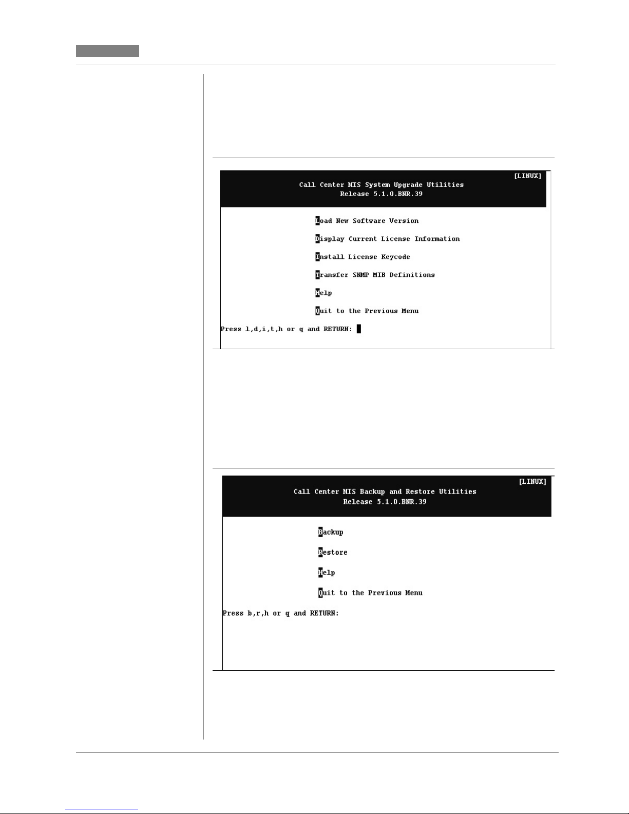
Release 5.2
CC MIS
CC MIS
System upgrade utility menu
The system upgrade utility menu provides access to commands used
for upgrading software versions.
Figure 3.5 System upgrade utility menu
Backup and restore menu
The backup and restore menu provides access to commands used f or
customer backup of data. It provides for the restoration of data in the
event of data corruption.
Figure 3.6 Backup and restore menu
CC MIS Maintenance Guide 3-13
Page 64

CC MIS
t
Release 5.2
Run state utilities menu
The run state utilities menu provides access to commands used for
start-up and shutdown of the CC MIS system and individual partitions,
and contains the update switch configuration data command (formerly available in the Supervisor interface).
Figure 3.7 Run state utilities menu
Diagnostics menu
The diagnostics menu provides access to diagnostic programs for
CC MIS.
Figure 3.8 Diagnostics menu
3-14 297-2671-545
Note:
The File Transfer command is available only and
displayed on this menu if you are logged in through
the maintenance modem. This command is no
available on the PowerPC platform.
Page 65

Release 5.2
4
Section 4: Shutdown, Startup,
and Power down
CC MIS
CC MIS
Shut down CC MIS
Start up CC MIS
Power down CC MIS
Introduction
This chapter contains procedures for the following commands and
functions: shut down, start up, and power down CC MIS.
Shut down CC MIS
CC MIS must be manually shut down before certain functions are performed through the maintenance console. (CC MIS is automatically
shutdown for functions requiring shutdown.) The shutdown command
leaves the operating system and other non-CC MIS software running.
The system is shut down from the Run State Utilities menu.
Figure 4.1 Run state utilities menu
Power up CC MIS
Power failures
CC MIS Maintenance Guide 4-1
Page 66

CC MIS
Release 5.2
Start up CC MIS
Perform a start up of CC MIS if you shutdown CC MIS.
Start up/shut down partitions
Perform start up and shut down of CC MIS partitions from the Run
State Utilities menu. It is also available in Partition Configuration
screen (refer to Chapter 7).
Power down CC MIS
The Power down command is used to remove power to CC MIS. The
power down command is selected from the Run State Utilities menu.
Use the power button to power up CC MIS after a
Note:
power down.
Shut down CC MIS
Using this command shuts down the CC MIS software, leaving the operating system, non-CC MIS programs, and CC MIS maintenance
software running.
If you want to shut down both the CC MIS software
Note:
If you request a maintenance function that can only be performed with
CC MIS shutdown, the maintenance and administration software automatically shuts down CC MIS. The system does not need to be shut
down manually. (The exceptions are the Test All I/O Ports function
and changing the Network Name, both of which require manual shutdown.)
and the UNIX operating system, you must use the
power down command.
Automatic logout
CC MIS supervisor's are automatically logged out
if the CC MIS system is shut down.
4-2 297-2671-545
Page 67

Release 5.2
Step 4-1: Shutting down CC MIS
CC MIS
CC MIS
Perform the steps below to manually shut down CC MIS.
1. Ensure that CC MIS is operating and access the Maintenance and
Administration menu.
CC MIS shutdown
Advise supervisors that you are shutting down the
CC MIS system. Supervisors do not have access to
CC MIS after you have shut down the system.
2. Enter r to display the Run State Utilities menu.
3. From the Run State Utilities menu, enter s to shut down the CC MIS
system. The system displays the following warning:
WARNING!
Proceeding with this operation will bring down all CC MIS software.
Ready? (yes/quit)
4. Enter y.
Note: Enter q to abort the shut down and return to the menu.
The system displays the following message:
CC MIS terminating. . .
CC MIS has been s hutdown.
Use the Start the CC MIS System command to restart it.
Press RETURN to continue.
5. Press <Return>.
The system displays the Run State Utilities menu. The third option has
changed to Start the CC MIS System.
CC MIS Maintenance Guide 4-3
Page 68

CC MIS
e
t-
Step 4-2: Starting CC MIS
Start up CC MIS
This command starts up CC MIS after it has been shut down (not powered down). CC MIS is started after certain maintenance tasks have
been completed, such as automatically testing all configured ports.
Perform the steps below to start CC MIS.
Release 5.2
1. Access the Maintenance and Administration menu.
2. Enter r to display the Run State Utilities menu.
3. From the Run State Utilities menu, enter s to start the CC MIS
system.
Note: CC MIS must be shut down to access the correct option.
The system displays the following messages:
Start the CC MIS system
Is the date and time [date and time] correct? (yes/no/quit)
Note: If the time and date are wrong, enter n. Th e prompt Enter the
correct time and date [mmddHHMMyy]: is displayed. Enter correct time and dat
and press the <Return> key. The syst em displays the following message again:
Is the date and time [date and time] correct? (yes/no/quit)
Note: The time and date for the system are spe ci fied here (not read from the
switch - unless link is synchro nized with switch). If the system experience s “drif
ing time" it will need to be shut down and restarted and the date/time specified
again.
4. Enter y.
Note: Enter q to abort the startup and return to the menu.
The system displays the following messages:
Starting CC MIS. . . .
CC MIS has been started.
Press RETURN to continue.
5. Press <Return>.
The system displays the Run State Utilities menu. The third option has
changed to Shutdown the CC MIS System.
4-4 297-2671-545
Page 69

Release 5.2
Step 4-3: Power down CC MIS
CC MIS
CC MIS
Power down CC MIS
This command powers down both CC MIS and the UNIX operating
system. You power down CC MIS when you want to stop running all
software or remove power from the system in order to service hardware or move the system.
Perform the steps in below to power down CC MIS.
1. Access the Maintenance and Administration menu.
2. Enter r to display the Run State Utilities menu.
3. Enter d to power down the CC MIS system and the UNIX operating
system. The system displays the following warning:
Prepare the system for powering down.
This command shuts down the CC MIS system (if it is currently
running), then shuts down the operating system in preparation for
removing power from the system.
Ready (yes/quit)?
4. Enter y. (To quit and return to the menu, enter q.)
The system displays the following message:
The actual message displayed in Step 4 differs
slightly between platforms.
On the PowerPC platform the actual NOTICE
text is different than the text shown in this example.
CC MIS terminating ...
Beginning operating system shutdown.
SHUTDOWN started
Tues Apr6 14:11:40 CDT 1995
THE SYSTEM IS BEING SHUT DOWN NOW ! ! !
Log off now or risk your files being damaged.
CC MIS shutdown
Advise supervisors t hat you are powering down the
CC MIS system. Supervisors do not have access to
CC MIS after you have powered down the system.
CC MIS Maintenance Guide 4-5
NOTICE: System secured for powering down.
WAIT - corrupted files
After performing step 4, the user must wait for th e message
NOTICE: System secured for powering down
before proceeding to step 5. Failure to wait may result in corrupted files on the disk.
5. After the message NOTICE: System secured for powerin g down is
displayed, turn off power with the power button on the front o f the VME.
6. Unplug power cord from the wall outlet or UPS. (Recommended)
Page 70

CC MIS
t
Step 4-4: Powering up CC MIS
Release 5.2
Power up the CC MIS system
The steps are used to power up both CC MIS and the UNIX operating
system. Power up CC MIS after it has been powered down using the
power down command. Perform the steps below to start CC MIS.
Perform only step 1 if the system was running bu
Note:
1. Turn on power with the power button on th e VME.
was powered down. Perform all of the steps if the
system was shutdown prior to power down.
2. After the system has completed start up, the system displays the
following prompt:
Console login:
Note: System start up may take several minutes.
3. Enter maint The system displays the following prompt:
Password:
4. Enter the password. The Maintenance and Administration menu is
displayed.
5. Select the Run State Utilities option. The Run State Utilities menu is
displayed.
6. Enter s to start the CC MIS System. If the CC MIS was running before
the system was powered down, it will automatically be restarted.
The system displays the following messages:
Start the CC MIS system
Time:
Date:
Ready? (yes/quit)
7. Enter y. (Enter q to abort the startup and return to the Maintenance and
Administration menu.) The system displays the following messages:
4-6 297-2671-545
Starting CC MIS. . . .
CC MIS has been started.
Press RETURN to return to the Main Menu.
8. Press <Return>
The system displays the Run State Utilities menu. The third option of
the menu has changed to “Shutdown the CC MIS System" because th e
CC MIS is operating.
Page 71

Release 5.2
Step 4-5: Recovering from a power fail-
CC MIS
CC MIS
Power failures
The CC MIS system uses a Uninterruptable power supply (UPS) to retain power during power failures. If a power failure exceeds the UPS
capability, then the CC MIS system must be powered down.
Note: When a power failure occurs, the user receives console messages stating that the system will shutdown in “xx" minutes. These messages appear every two minutes until the count is down to zero
minutes. Afterwards, the system begins the shutdown process.
CC MIS was not running
If CC MIS was not running when the power failure occurred, perform
the steps in Step 4-4 (on the previous page) to power up CC MIS.
CC MIS was running
If CC MIS was running when the power failure occurred, perform the
step below to recover from the power failure.
ure
1. Turn on power with the power button on th e VME.
2. CC MIS will automatically restart.
CC MIS Maintenance Guide 4-7
Page 72

CC MIS
Release 5.2
4-8 297-2671-545
Page 73

Release 5.2
5
Section 5: Backing up and
Restoring data
CC MIS
CC MIS
Accessing the backup and restore func tions
Using a DATs tape and drive
Backing up custom er data
Restoring customer data
Introduction
The Backup and Restore Utilities allows the following functions to be
performed
• backup customer data to tape
• restore customer data from tape
These functions are accessed through the Backup and Restore Utilities
menu, as shown in the figure below.
Figure 5.1 Backup and restore menu
CC MIS Maintenance Guide 5-1
Page 74

CC MIS
Step 5-1: Accessing the backup and re-
Release 5.2
The restore functions must be performed when the affected partitions
are stopped, while the backup functions can be performed when the affected partitions are running or stopped. CC MIS must be running in
order for backup or restore functions to be performed.
Perform the step below to access the backup and restore utilities.
store menu
1. Enter b to access the backup and restore utilities menu.
The system displays the Backup and Restore Utilities menu.
Using the DAT drive for backups
The DAT tape drive is used to backup customer data and to install and
upgrade new software versions.
Figure 5.2 DAT drive unit
The system can be configured to perform an automatic backup each
evening. If your system is configured for backups, be sur e to leave a
tape in the drive to record the backup.
Valid current data
5-2 297-2671-545
Rotate backup tapes daily to ensure that you have a
tape with valid current data from which to restore.
Page 75
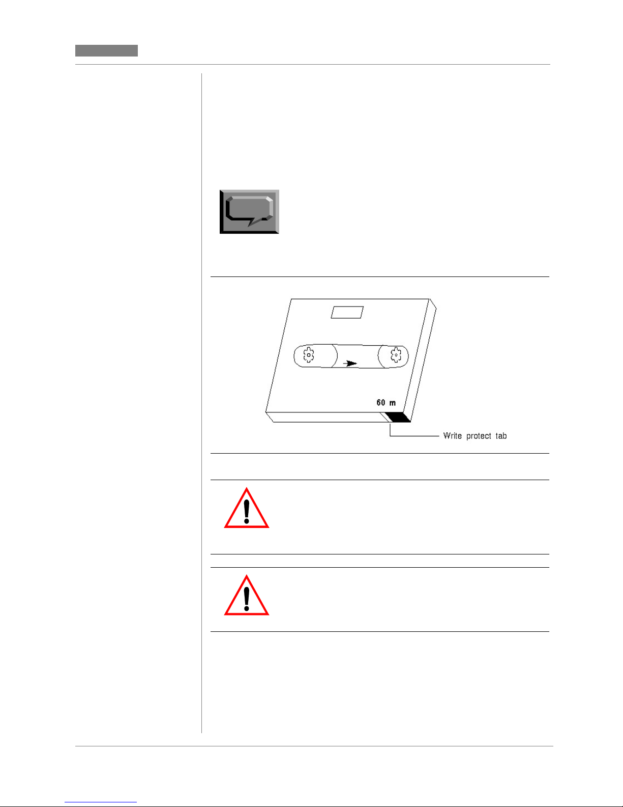
Release 5.2
CC MIS
CC MIS
Write-protecting your DAT
After backing up data, you may want to protect the tape from being
written over. A write protect setting exists on the DAT, illustrated in
Figure 5-3. To protect the contents of the tape, use your fingernail to
move the white tab to the left. The figure below illustrates the setting
for a write protected tape. To allow da ta to be written on a t ape, move
the white tab to the right.
Note:
Figure 5.3 Digital audio tape
The white tab must be all the way to the right in
order to record data on a backup tape.
Use correct tape drive
for backups
On systems with both a DAT drive and a cartridge
tape drive, the DAT must be used backups. Do not
use the cartridge tape drive for backups.
CC MIS Maintenance Guide 5-3
Damage to tape drive
Do not unload the backup tape from the tape drive
during a backup. Unloading the tape may cause
damage to the tape drive.
Page 76

CC MIS
Step 5-2: Inserting a DAT tape into the
Step 5-3: Ejecting a DAT tape from the
Release 5.2
Perform the steps below when inserting a DAT in the drive. Refer
to steps in this chapter to back up data.
tape drive
1. If the tape is for a backup or database upgrade, ensure the t a pe is
not write protected. Otherwise, the tape should be write protected.
2. Hold the tape so that the write protect mechanism is on the right,
and the tape label is up.
3. Insert the tape in the drive.
The system readies the tape, and the ready light glows green.
Use the steps below to eject a DAT from the drive.
tape drive
1. Press the eject button (when amber light is off).
The system ejects the tape.
Backing up customer data
The Backup command stores information from the CC MIS databases
to tape. For systems equipped with a DAT drive and a cartridge tape
drive, data is stored using the DAT drive. For systems equipped with
a cartridge tape drive only, data is stored using the cartridge tape drive.
You can only back up customer data when the CC MIS system is operating. Backing up customer data records the following information:
• definitions database for selected partitions
• data database for selected partitions
• configuration database
5-4 297-2671-545
Page 77

Release 5.2
Note: Systems that store more
than 2 GBytes of data may not
be able to perform an unattended nightly back up. The
information being backed up
may not fit on a sing le DAT
tape.
CC MIS
CC MIS
Automatic backups
The CC MIS system automatically performs backups every 24 hours,
if the "Nightly Backups" is enabled for the partition. It will backup every partition for which this option is enabled (see partitions options in
Chapter 7). To verify that your daily databa se backup has been successful, view the error log and look for one of the following messages:
Nightly Backup was successful, or Nightly Backup failed. To keep
one week of data as a backup, use a total of seven tapes for the daily
backup. Change the tape each day, storing the tape from the previous
day. Reuse the tapes in a seven day cycle. (Do not exceed the tape
manufacturer's recommended usage.)
The number of days, weeks, or months that data is stored is determined
by the parameters set through the storage calculator. The specified duration identifies the period of time data is saved before being automatically purged from the database.
Manual backups
Manual backups provide additional control over what is backed up.
The manual selections for BACKUP and RESTORE are as follows:
• For configuration only backup and restore - This backs up and
restores the information defined through the maintenance configuration screens.
• For partition/definition database only - This backs up and restores
the information defined through admin, reports, displays, config
screens, and so on. That includes all definitions that were created
by the supervisor.
• For partition/data database only - This backs up only historical
statistics. This is the data used in the cus tom and standard reports.
This is NOT data shown on real-time displays. (Not applicable
for NAPs.)
CC MIS Maintenance Guide 5-5
Page 78

CC MIS
Release 5.2
If the system crashed and you need to restore all data, you restore the
configuration data first, then you restore both the partition/system database and partition/data database to restore all data for all partitions.
Note:
Figure 5.4 Backup screen
The Backup screen is shown with a sample ad hoc backup set.
The default "Backup?" value will be "yes" for the configuration database.
There is no difference between manual and nightly
backups when all options are selected during a
manual backup.
The default "Backup?" value for each partition is "yes" if the nightly
backup for the partition is enabled (see Partition Options in
Chapter 7).
The default for NAPs is “yes” for Definition Database only.
The lower portion of the screen displays information about the current
backup. Messages such as "Insert new tape" are displayed in this area.
The tape number and item being backed up are also displayed.
Backup screen commands
The following commands are accessed on the Backup screen by pressing the F1 soft-key.
5-6 297-2671-545
Page 79

Release 5.2
CC MIS
CC MIS
Table 5-1: Backup screen commands
Command Function
Exit Exits the current screen.
Start backup Initiates an ad hoc backup.
Continue backup Used to continue backup when end-
of-tape is reached or some other
recoverable error has occurred.
Cancel backup Cancels the current backup (after con-
firmation).
View backup log Allows the user to view the backup log
without having to go through the Logs
screen.
Constraints
This procedure only backs up CC MIS data; it does not store information from the ACD database tables on the DMS-ACD.
Note:
You can back up customer data only when the CC
MIS system is operating.
Damage to tape drive
Do not unload the backup tape from the tape drive
during a backup. Unloading the tape may cause
damage to the tape drive.
Use correct tape drive
If your system has both the DAT drive and the cartridge tape drive, you must use the DAT drive to
back up customer data.
CC MIS Maintenance Guide 5-7
Page 80

CC MIS
.
Step 5-4: Backing up customer data
Release 5.2
Guidelines
Use the steps below to back up customer data.
1. Access the Backup and Restore Utilities menu.
2. Enter b to back up customer data.
The system displays the Backup screen.
3. Move cursor to the backup field for the partition and press the Options
function key for the Options menu. Select the de sired setting [1 . No, 2. Yes, 3
Yes (Definition Only), or 4. Yes (Data Only)].
4. Press the Commands function key to display the commands menu .
5. Select the Start Backup command (item 2).
6. A pop-up dialog box appears with the following message:
Insert a blank tape and wait until the tape drive is ready. Press "y"
when ready, "q" to quit.
Ready? (y/q)
7. Enter y to begin the backup.
8. During the backup process, view the Backup Inf ormation area of the
Backup screen for important information and messages regarding the
progress of the backup.
Note: A message will be displayed when a new tape needs to be
inserted. This area will also display the tape number and the name
of the item being backed up.
9. When prompted, remove the tape from the cartridge tape drive by
moving the eject latch from the right to the left or by pressing the eject
button.
10. To exit the Backup screen, press the Commands function key and
select the Exit option.
The Backup and Restore Utilities menu is displayed.
5-8 297-2671-545
Page 81

Release 5.2
)
CC MIS
CC MIS
Restoring customer data from tape
The Restore command can be used to restore customer data from a
backup tape in the event of a disk crash or other data corruption. This
process loads backup copies of the CC MIS database from a tape and
replaces existing databases.
Therefore, this procedure should be performed only if the existing data
has been corrupted or is no longer valid.
This procedure restores the following information from tape:
• definitions database for selected partitions
• data database for selected partitions (not applicable for NAPs)
• configuration database
Constraints
You can restore data from a backup tape only when the CC MIS software is operating.
Release 4.1 / 5.0
The system will not allow a
backup tape created on
another CC MIS release to be
restored onto the 5.0
system.
Note:
Corrupted data
Be sure that the softwar e release of CC MIS used to
create your backup tape matches the software release of CC MIS that restores the data. Data will be
corrupted and the system may not function as designed if the releases do not match.
Improper database size
When restoring a database from a backup tape, the
size of each partition's historical database on the
backup tape must be the same size or smaller than
the configured storage limit.
Restoring a backup that was performed prior to
hardware changes (for example, removing a disk
may result in configuration problems.
CC MIS Maintenance Guide 5-9
Page 82

CC MIS
.
Release 5.2
Figure 5.5 Restore screen
The Restore screen is shown with a sample ad hoc backup set. The
lower portion of the screen displays information about the current restoration. Messages such as "Insert tape" are displayed in this area. The
tape number and item being restored are also displayed.
Note:
The Restore process for the configuration database
cannot be performed if any partitions are running
Restoration of a partition also requires that partition
be stopped.
5-10 297-2671-545
Page 83

Release 5.2
Step 5-5: Restoring customer data
Perform the steps below to restore customer data from tape.
1. Access the Backup and Restore Utilities menu.
2. Enter r to restore c ustomer data. The system displays the Restore
screen.
Note: The Restore process for the configur ation database cann ot be
performed if any partitions are running. Restoration of a partition also
requires that partition be stopped. A prompt is displayed to shut
down the partition(s), as needed.
3. On the restore screen, identify the configuration database or partition
data to be restored. (Use the Options function key to display the Options
menu.)
4. Press the Commands function key to display the commands menu.
5. Select the Start Restore command. A pop-up dialog box a ppears that
may include the following messages:
CC MIS
CC MIS
Warning: the existing contents of each database being
restored will be removed immediately before
the database is restored from tape.
Warning: restoring the configuration database with a different
hardware configuration than the current system may
have undesirable results.
Warning: restoring the configuration database will shutdown
ALL partitions.
Are you sure? (y/q)
6. Enter y to continue.
Note: Enter q to abort the restore process.
If you enter y, the following message appears:
Insert the tape and wait until the tape drive is ready. Press "y"
when ready, "q" to quit.
Ready? (y/q)
Note: Use the cartridge tape drive or the DAT drive, depending on your
system configuration and available disk size.
7. Enter y to restore data from tape. Enter q to abort the restore process.
CC MIS Maintenance Guide 5-11
Continued on next
page ...
Page 84

CC MIS
Release 5.2
(continued)
8. During the restore process, view the Restore Information area of the
Restore screen for important information and messages regarding
the progress of the backup.
Note: A message will be displa yed when a new tape needs to be
inserted. This area will also display the tape number and the name of
the item being backed up.
9. When prompted , remove the tape from the cartridge tape drive by
moving the eject latch from the right to the left or by pressing the eject
button.
10.To exit the Backup screen, press the Commands function key and
select the Exit option.
The Backup and Restore Utilities menu is displayed.
Note: Partitions stopped by the Restore process must be manually
restarted.
5-12 297-2671-545
Page 85

Release 5.2
6
Section 6: Configuring the
CC MIS system
CC MIS
CC MIS
System configuration screen
Port Allocation screen
Switch link configuration
Networked
CC MIS
If you are using the
networking feature,
refer to the information in
Chapter 8.
Terminal server configuration screen
SNMP configuration screen
System configuration reports
Introduction
Through the Configuration main menu, you access submenus that allow you to define or alter parameters related to CC MIS system configuration. The procedure for establishing a CC MIS system is as
follows:
• System configuration screen - specify system name, LAN param-
eters, and maintenance printer.
• Switch link configuration - select link type and specify link infor-
mation.
• T erminal server configuration - specify LAN-based terminal serv-
ers available for CC MIS.
CC MIS Maintenance Guide 6-1
• Partition configuration - add a partition, then specify the follow-
ing:
- connection parameters
- partition options
- storage calculator
- disk allocation
- serial terminals
- static LAN terminals
- printers
- wallboards
- master privilege definition
You access the Configuration main menu, as shown in Figure 6-1,
from the Maintenance and Administration menu.
Page 86

CC MIS
Step 6-1: Accessing the Configuration
Release 5.2
Figure 6.1 Configuration main menu
Note: The Physical network Configuration option is only displayed on
a networked node.
Accessing the Configuration main menu
You access all configuration functions from the Configuration main
menu. CC MIS must be running to perform configuration.
Guidelines
Perform the steps below to access the Configuration main menu.
1. Access the Maintenance and Administration menu.
2. Select c to access the Configuration main menu.
The system displays the Configuration main menu .
menu
6-2 297-2671-545
Page 87

Release 5.2
CC MIS
CC MIS
System Configuration
The system configuration screen contains system-wide data. This is
the first screen accessed when setting up a new system. Information
contained in this screen includes system name, network parameters,
and the maintenance printer setup.
Figure 6.2 System configuration screen
PowerPC platform version
88K-based platform version
CC MIS Maintenance Guide 6-3
Page 88

CC MIS
Step 6-2: Accessing the System Configu-
Release 5.2
Guidelines
Perform the steps below to access the System Configuration screen.
ration screen
1. Access the Maintenance and Administration menu.
2. Select Configuratio n to access the Configuration main menu.
The system displays the Configuration main menu.
3. Select System Configuration to access the System Configuration
screen.
Field descriptions
The system configuration screen fields are described in Table 6-1.
Table 6-1: System configuration field descriptions
Field Description
System Name The system name will appear on con-
Network Hostname This name can be up to 15 characters
Network Address This is the network IP address that
Netmask Used by routers to determine which
figuration reports. This name can be
up to 16 characters in length.
in length. This is the name that appears when the "uname - n" comman d
is executed o n the sys tem at th e UNIX
prompt.
uniquely identifies the system on the
LAN.
bits of an IP address is the network address.
6-4 297-2671-545
Default Gateway Address of the gateway to the network
on which CC MIS is located.
Page 89

Release 5.2
Table 6-1: System configuration field descriptions
Field Description
CC MIS
CC MIS
Maintenance Printer
(187 or 197 platforms)
Unix Printer
(PowerPC platforms)
Printer where the maintenance reports
and logs are spooled. This is a directconnect, hard-wired printer. The
maintenance printer can be added to
any port which is not currently in use
by a partition.
Press the Options menu to select ports,
modem, baud rate, and printer models.
(Up to 25 characters can be entered for
the printer name.) Use the port allocation key to view port allocations.
Note 1: The maintenance (system)
printer can be connected to the VME
using the parallel port.
Note 2: Graphical reports cannot be
printed on the Maintenance Printer.
Designated (unix-defined) printer
where the maintenance reports and
logs are spooled.
Printers on the PowerPC m ust first be
configured using the Add a Unix
Printer command in the Operating
System Configuration menu before
they can be configured into CC MIS.
CC MIS Maintenance Guide 6-5
Page 90

CC MIS
s
Release 5.2
Port Allocation
The Port allocation screen is a view-only screen. It allows you to view
a list of ports on the system and identifies the partition to which they
are allocated. To change the port allocations, you must access the Port
Configuration screen (described in Chapter 7).
Figure 6.3 Port Allocation screen
Constraints
Port console is configured as a console device, and port contty is always configured as a dialup maintenance device for system maintenance. You cannot change these port assignments. These ports, along
with the Maintenance printer, belong to the base partition.
Ports contty02 and contty03 are located on the main processor board.
Configuring devices on these ports requires more processor time than
if you use the other available ports. If you use these ports to connect
an ASCII (dumb) terminal, you need to use line drivers or null modems.
Note:
Port lp0 is the parallel printer port located on the processor board.
There are no modem or baud rate fields associated with this port.
These ports are not recommended for Window
PCs.
6-6 297-2671-545
Page 91

Release 5.2
Step 6-3: Accessing the Port Allocation
CC MIS
CC MIS
Guidelines
Perform the steps below to view the port allocation screen.
screen
1. Access the Port Allocation screen by p r essing the Port Allocation
function key from the System Configuration screen.
2. Select Exit to return to the Main Menu.
CC MIS Maintenance Guide 6-7
Page 92

CC MIS
Step 6-4: Accessing the Switch Link
Release 5.2
Switch link configuration
The switch link configuration screen allows you to create multiple link
definitions. Links can be live or simulated. This function provides a
means of defining logical links that can be used by a partition. Ther e
can be up to six link definitions in the switch link configuration screen
- four live and two simulated. (Note that on a PowerPC there c an be
12 live links.)
Upon entering the switch link configuration, the screen appears as
shown in Figure 6-4.
Figure 6.4 Switch link configuration screen - Initial
Guidelines
Perform the steps below to access the Switch Link Configuration
screen.
1. Access the Maintenance and Administration menu.
6-8 297-2671-545
2. Select Configuratio n to access the Configuration main menu.
The system displays the Configuration main menu.
3. Select Switch Link Configuration to access the Switch Link
Configuration screen.
Configuration screen
Page 93

Release 5.2
CC MIS
CC MIS
Command menu options
The Switch Link Configuration screen has the following commands
on the commands menu:
• Exit
• Clear the form
• Read an existing link definition
• Save link definition
• Delete an existing link definition
Live link
If live is chosen as the link type, the remainder of the fields are displayed on the screen. The switch link configuration screen for a live
link appears as shown in Figure 6-5.
Live link definitions are specified to obtain a live connection to the
DMS/MSL-100.
Switch Codes
The Switch Code field allows
three additional digits to be
prepended to all direct ory
numbers (DNs) received from
the switch. This field is normally
left blank. Thi s field should be
used if you are using the CC MIS
networking feature in a private
network where duplicate DNs
appear on more than one switch.
Using a unique switch code for
each switch in the private
network, CC MIS can make the
duplicated DNs unique, thereby
allowing the CC MIS
networking feature to operate
properly.
Figure 6.5 Switch link configuration screen - live link
The Reinit Time field is used to specify a time (in 24-hour format) that
the system will request re-initialization from the switch. This field is
left blank when no daily re-initialization is required.
CC MIS Maintenance Guide 6-9
The secondary link field is available only if the link redundancy option
is enabled on the load tape. It can be left blank if link redundancy is
not desired for this live link definition.
Time for the system is set and timezone differences are adjusted using
the Synchronize to Switch Time and Timezone Adjustment fields.
Page 94

CC MIS
-
Release 5.2
Note: In Release 5.1, partitions on a single node can have different
time zones than the rest of the system. This feature is set using the
Partition Options screen.
On the PowerPC, the DTE/DCE setup for a port is dete rmined by the
hardware and cannot be changed. This setting can be changed on 88Kbased platforms.
Simulator link
If simula tor is chosen as the li nk type, the Simulator Configuration
field is displayed on the screen. The Switch Link Configuration screen
for a simulator link appears as shown in Figure 6-6.
Simulator link definitions are specified to set aside a link number to
specify that a partition should be connected to the simulator.
Figure 6.6 Switch link configuration screen - Simulator link
6-10 297-2671-545
Note:
The configuration information is explained in the
Help text. Select the text and press the Help func
tion key to view the Help text.
Page 95

Release 5.2
Step 6-5: Accessing the Terminal Server
CC MIS
CC MIS
Terminal Server Configuration
The Terminal Server screen allows you to specify LAN-based terminal servers that are available for CC MIS.
Figure 6.7 Terminal Server screen
Guidelines
Perform the steps below to access the Terminal Server Configuration
screen.
screen
1. Access the Maintenance and Administration menu.
2. Select Configuratio n to access the Configuration main menu.
The system displays the Configuration main menu.
3. Select Terminal Server Configur at ion to access the Terminal Server
Configuration screen.
CC MIS Maintenance Guide 6-11
Page 96

CC MIS
Release 5.2
Adding a Terminal Server
To add a new terminal server, press the Add function key. The dialog
(shown in the figure below) appears on the screen. Enter the IP address
and press the <Return> key.
Figure 6.8 Adding a Terminal Server
Configuring a Terminal Server
To configure a terminal server, press the Configure function key. The
dialog (shown in the figure below) appears on the scre en. Follow the
instructions on the screen to enter and configure the terminal server.
Figure 6.9 Configuring a Terminal Server
6-12 297-2671-545
Page 97

Release 5.2
CC MIS
CC MIS
Editing a field
To edit the fields of a terminal server listed on the Terminal Server
screen, press the Edit Field function key.
Figure 6.10 Editing a field on the Terminal Server screen
CC MIS Maintenance Guide 6-13
Page 98

CC MIS
,
s
Release 5.2
SNMP configuration
The SNMP configuration screen displays information concerning the
three CC MIS SNMP communities: Read-only, Read-wri te, and Trap.
These communities consists of:
• community name
• access mode
• set of IP addresses (of SNMP managers)
Due to the technical nature of the SNMP capabil ity
Note:
The SNMP configuration screen is used to define Network Management Systems (NMS) that may have access to the system-wide information defined by the Management Information Bases (MIBs). The
two types of MIBs are:
a background in network management and the
SNMP protocol is recommended for administrator
and users of this feature.
• CC MIS System MIB
• MIB-2 (standard MIB)
The SNMP configuration screen is shown in the figure below.
Figure 6.11 SNMP configuration
6-14 297-2671-545
Page 99

Release 5.2
CC MIS
CC MIS
Field descriptions
The SNMP configuration screen fields are described in the table
below.
Table 6-2 : SNMP field descriptions
Field Description
Community The communities are as follows:
Read-only - Lists the IP addresses of
SNMP managers who may query MIB
variables.
Read-write - Lists the IP addresses of
SNMP managers who may both query
and set MIB variables.
Trap - Lists the IP addresses of SNMP
managers who are to receive traps
generated by the system MIBs.
Name This name can be 1 to 15 charac ters in
length. Any character except the vertical bar can be used. The Read-only
and Read-write communities can have
the same name, However it is not recommended. When they both have the
same name, the Read-write community member list is searched first.
Members This area lists the IP addresses of
SNMP managers that have access to
the community. An entry of 0.0.0.0 is
used to indicate that all SNMP mangers are considered part of that community.
Note: The 0.0.0.0 cannot be used in
the Trap community because CC MIS
needs an explicit list t o which traps are
to be sent.
CC MIS Maintenance Guide 6-15
Page 100

CC MIS
Step 6-6: Accessing the SNMP Configu-
Release 5.2
Guidelines
Perform the steps below to access the SNMP Configuration screen.
ration screen
1. Access the Maintenance and Administration menu.
2. Select Configuratio n to access the Configuration main menu.
The system displays the Configuration main menu.
3. Select SNMP Configuration to access the SNMP Configuration screen.
6-16 297-2671-545
 Loading...