

Page 1

Nortel CallPilot
201iServerHardwareInstallation
Clicking on a PDF hyperlink takes you to the appropriate page. If necessary,
scroll up or down the page to see the beginning of the referenced section.
NN44200-301
.
ATTENTION
Page 2

Document status: Standard
Document version: 01.01
Document date: 15 February 2007
Copyright © 2007, Nortel Networks
All Rights Reserved.
Sourced in Canada
The information in this document is subject to change without notice. The statements, configurations, technical
data, and recommendations in this document are believed to be accurate and reliable, but are presented without
express or implied warranty. Users must take full responsibility for their applications of any products specified in this
document. The information in this document is proprietary to Nortel Networks.
The process of transmitting data and call messaging between the CallPilot server and the switch or system is
proprietary to Nortel Networks. Any other use of the data and the transmission process is a violation of the user
license unless specifically authorized in writing by Nortel Networks prior to such use. Violations of the license by
alternative usage of any portion of this process or the related hardware constitutes grounds for an immediate
termination of the license and Nortel Networks reserves the right to seek all allowable remedies for such breach.
Trademarks
*Nortel, the Nortel logo, the Globemark, and Unified Networks, BNR, CallPilot, DMS, DMS-100, DMS-250,
DMS-MTX, DMS-SCP, DPN, Dualmode, Helmsman, IVR, MAP, Meridian, Meridian 1, Meridian Link, Meridian
Mail, Norstar, SL-1, SL-100, Communication Server 1000, Supernode, Contact Center, Telesis, and Unity are
trademarks of Nortel Networks.
3COM is a trademark of 3Com Corporation.
ADOBE is a trademark of Adobe Systems Incorporated.
ATLAS is a trademark of Quantum Corporation.
BLACKBERRY is a trademark of Research in Motion Limited.
CRYSTAL REPORTS is a trademark of Seagate Software Inc.
EUDORA and QUALCOMM are trademarks of Qualcomm, Inc.
ETRUST and INOCULATEIT are trademarks of Computer Associates Think Inc.
DIRECTX, EXCHANGE.NET, FRONTPAGE, INTERNET EXPLORER, LINKEXCHANGE, MICROSOFT,
MICROSOFT EXCHANGE SERVER, MS-DOS, NETMEETING, OUTLOOK, POWERPOINT, VISUAL STUDIO,
WINDOWS, WINDOWS MEDIA, WINDOWS NT, and WINDOWS SERVER are trademarks of Microsoft Corporation.
GROUPWISE and NOVELL are trademarks of Novell Inc.
INTEL is a trademark of Intel Corporation.
LOGITECH is a trademark of Logitech, Inc.
MACAFEE and NETSHIELD are trademarks of McAfee Associates, Inc.
MYLEX is a trademark of Mylex Corporation.
NETSCAPE COMMUNICATOR is a trademark of Netscape Communications Corporation.
NOTES is a trademark of Lotus Development Corporation.
NORTON ANTIVIRUS and PCANYWHERE are trademarks of Symantec Corporation.
Page 3

QUICKTIME is a trademark of Apple Computer, Inc.
RADISYS is a trademark of Radisys Corporation.
ROLM is a trademark of Siemens ROLM Communications Inc.
SLR4, SLR5, and TANDBERG are trademarks of Tandberg Data ASA.
SONY is a trademark of Sony Corporation.
SYBASE is a trademark of Sybase, Inc.
TEAC is a trademark of TEAC Corporation.
US ROBOTICS, the US ROBOTICS logo, and SPORTSTER are trademarks of US Robotics.
WINZIP is a trademark of Nico Mark Computing, Inc.
XEON is a trademark of Intel, Inc.
All other trademarks and registered trademarks are the property of their respective owners.
Information for Japan
Japan VCCI Statement
The following applies to server models 1005r, 703t, 201i, and 1002rp:
This is a Class A product based on the standard of the Voluntary Control Council for Interference by Information
Technology Equipment (VCCI). If this equipment is used in a domestic environment, radio disturbance may occur, in
which case, the user may be required to take corrective action.
Page 4

Page 5

Publication History
February 2007
CallPilot 5.0, Standard 01.01 of the CallPilot 201i Server Hardware
Installation guide is issued for general release.
5
201i Server Hardware Installation
NN44200-301 01.01 Standard
Copyright © 2007, Nortel Networks Nortel Networks Confidential
.
Nortel CallPilot
5.0 15 February 2007
Page 6

6 Publication History
201i Server Hardware Installation
Nortel CallPilot
NN44200-301 01.01 Standard
Copyright © 2007, Nortel Networks Nortel Networks Confidential
.
5.0 15 February 2007
Page 7

Contents
Chapter 1 How to get help 9
Chapter 2 About the 201i server 11
201i server description 11
Network connectivity 18
Peripheral connectivity 22
Chapter 3 Preparing for installation 27
Installation overview 27
Unpacking and inspecting the 201i server 31
Switch and network requirements 33
Chapter 4 Installing the 201i server in a large Meridian 1
Overview 37
Repositioning the secondary backplane connector 39
Installing the 201i server in the large Meridian 1 switch 42
Removing the backplane (tip and ring) cables 43
Installing the NTRH3501 backplane cable 47
Installing the SCSI cables for Meridian 1 49
7
Reference Documents 11
system 37
Chapter 5 Installing the 201i server in an Option 11C or Option
11C Mini 55
Installing the 201i server in the Option 11C or Option 11C Mini switch 55
Section A: Installing Option 11C cables 58
Installing the intermediate SCSI cable for Option 11C 58
Section B: Installing Option 11C Mini cables 63
Installing the NTRH3502 SCSI cable for Option 11C Mini 63
Installing cables on the back of the Option 11C Mini cabinet 68
Chapter 6 Installing the 201i server in the Communication Server
1000 system 71
Communication Server 1000 description 71
Removing the Media Gateway or Media Gateway Expansion cover 75
Installing the 201i server 77
201i Server Hardware Installation
NN44200-301 01.01 Standard
Copyright © 2007, Nortel Networks Nortel Networks Confidential
.
Nortel CallPilot
5.0 15 February 2007
Page 8

8 Contents
Installing the NTRH3502 SCSI cable for Communication Server 1000 80
Replacing the Media Gateway or Media Gateway Expansion cover 82
Connecting cables to the Communication Server 1000 system 85
Chapter 7 Preparing peripheral devices 89
Overview 89
Setting the modem DIP switches 90
Setting the CD-ROM drive SCSI ID and DIP switches 92
Setting the tape drive SCSI ID 94
Setting SCSI device termination 95
Chapter 8 Connecting peripheral devices to the 201i server 99
Overview 99
Installing the MPCs 102
Installing the monitor, keyboard, and mouse 104
Connecting the CD-ROM and tape drives 105
Connecting the 201i server to the switch, ELAN subnet , and Nortel server
subnet 113
Connecting the modem 116
Completing the installation 118
Index 120
201i Server Hardware Installation
NN44200-301 01.01 Standard
Copyright © 2007, Nortel Networks Nortel Networks Confidential
.
Nortel CallPilot
5.0 15 February 2007
Page 9

Chapter 1
How to get help
This section explains how to get help for Nortel products and services.
Getting help from the Nortel Web site
The best way to get technical support for Nortel products is from the Nortel
Technical Support Web site:
h
ttp://www.nortel.com/support
This site provides quick access to software, documentation, bulletins, and
tools to address issues with Nortel products. More specifically, the site
enables you to:
•
download software, documentation, and product bulletins
• search the Technical Support Web site and the Nortel Knowledge Base
for answers to technical issues
9
•
sign up for automatic notification of new software and documentation
for Nortel equipment
•
open and manage technical support cases
Getting help over the phone from a Nortel Solutions Center
If you don’t find the information you require on the Nortel Technical Support
Web site, and have a Nortel support contract, you can also get help over the
phone from a Nortel Solutions Center.
In North America, call 1-800-4NORTEL (1-800-466-7835).
Outside North America, go to the following Web site to obtain the phone
number for your region:
h
ttp://www.nortel.com/callus
201i Server Hardware Installation
NN44200-301 01.01 Standard
Copyright © 2007, Nortel Networks Nortel Networks Confidential
.
Nortel CallPilot
5.0 15 February 2007
Page 10

10 Chapter 1 How to get help
Getting help from a specialist by using an Express Routing Code
Toaccess some Nortel Technical Solutions Centers, you can use an Express
Routing Code (ERC) to quickly route your call to a specialist in your Nortel
product or service. To locate the ERC for your product or service, go to:
h
ttp://www.nortel.com/erc
Getting help through a Nortel distributor or reseller
If you purchased a service contract for your Nortel product from a distributor
or authorized reseller, contact the technical support staff for that distributor
or reseller.
201i Server Hardware Installation
NN44200-301 01.01 Standard
Copyright © 2007, Nortel Networks Nortel Networks Confidential
.
Nortel CallPilot
5.0 15 February 2007
Page 11

Chapter 2
About the 201i server
In this chapter
"201i server description" (page 11)
"Network connectivity" (page 18)
"Peripheral connectivity" (page 22)
201i server description
Introduction
The 201i server is a flexible multimedia telephony server designed to
integrate with Nortel Meridian 1* and Communication Server*1000 products.
11
The 201i server occupies two slots of a Meridian 1 shelf or Communication
Server 1000 Media Gateway or Media Gateway Expansion. When the
server is locked into position, its connectors attach to the backplane, which
provides power and communications links.
Reference Documents
For a list of all CallPilot documents, see the following Customer
Documentation Map.
201i Server Hardware Installation
NN44200-301 01.01 Standard
Copyright © 2007, Nortel Networks Nortel Networks Confidential
.
Nortel CallPilot
5.0 15 February 2007
Page 12
12 Chapter 2 About the 201i server
201i Server Hardware Installation
Nortel CallPilot
NN44200-301 01.01 Standard
Copyright © 2007, Nortel Networks Nortel Networks Confidential
.
5.0 15 February 2007
Page 13

Primary components
The 201i server motherboard houses the interfaces needed:
•
to communicate with the Meridian 1 switch or Communication Server
1000 system.
•
to facilitate data communications on Ethernet networks.
Two Ethernet controllers on the 201i server motherboard provide Ethernet
capability. These controllers provide the network interfaces for both the
ELAN subnet and the Nortel server subnet. The connections to these
subnets are established by using the multi I/O cable described on "Multi I/O
cable description" (page 21).
Note: The secondary backplane connector connects the 201i server
to the second slot on the shelf, thereby providing access to the voice
channels provided by that slot.
The 201i server is shipped ready for installation into an Option 11C or Option 11C
Mini switch or Communication Server 1000 system. Before you install the 201i
server in a larger Meridian 1 switch (for example, Option 51C), you must move
the secondary backplane (DS30X) connector to the correct position. For more
information, see "Repositioning the secondary backplane connector" (page 39).
201i server description 13
ATTENTION
The following diagram shows the 201i server components:.
201i Server Hardware Installation
NN44200-301 01.01 Standard
Copyright © 2007, Nortel Networks Nortel Networks Confidential
.
Nortel CallPilot
5.0 15 February 2007
Page 14
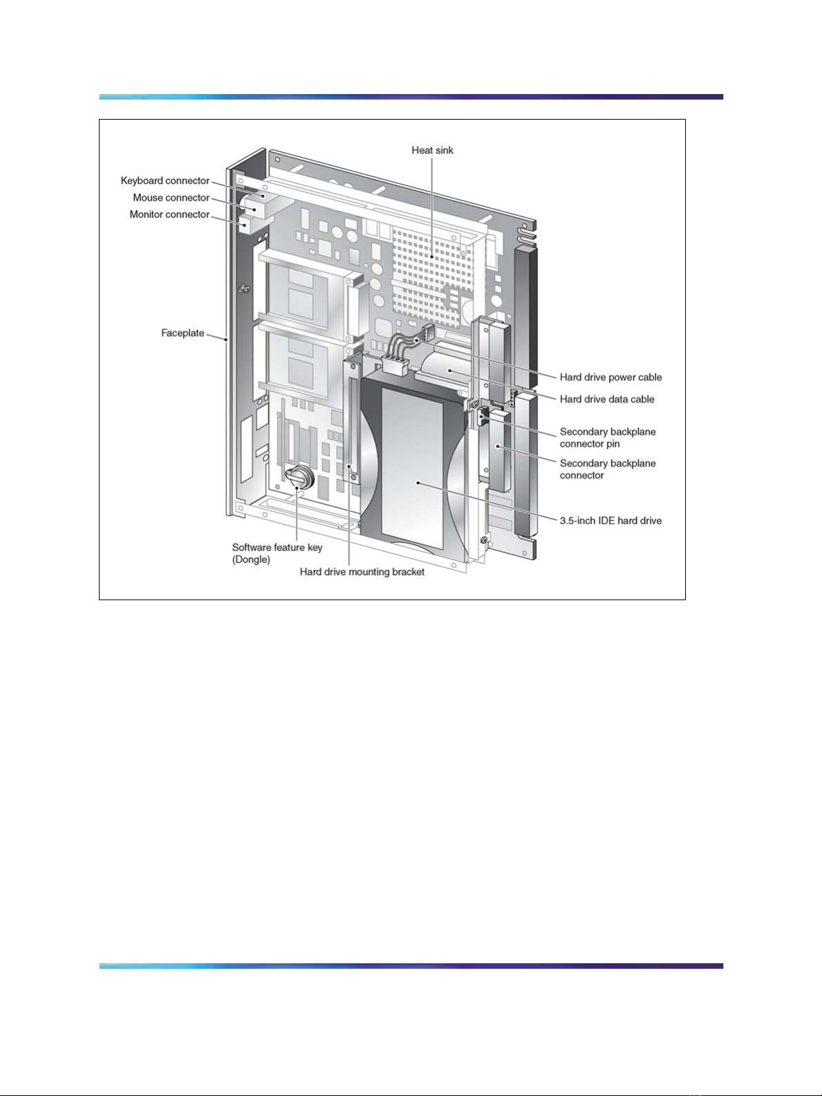
14 Chapter 2 About the 201i server
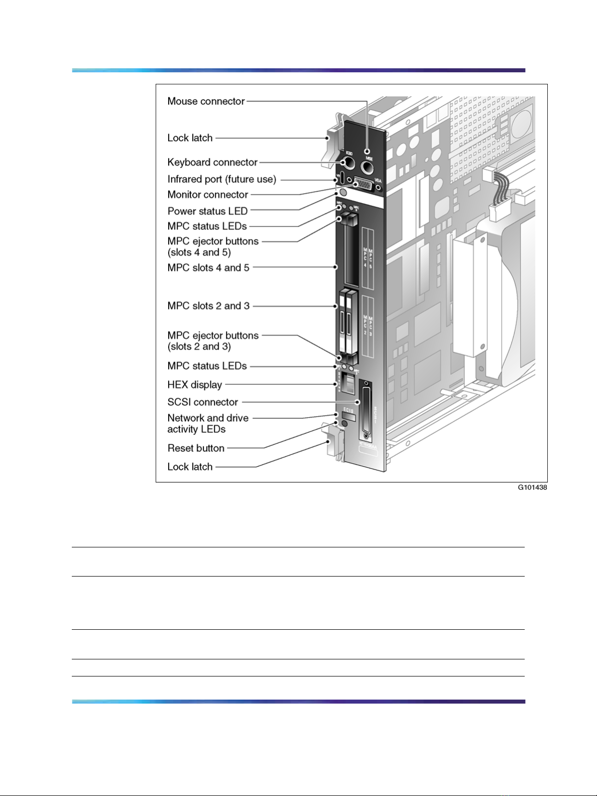
Faceplate
The following diagram shows the 201i server faceplate. The faceplate
provides LEDs, MPC card slots, and connectors for peripheral devices:
201i Server Hardware Installation
NN44200-301 01.01 Standard
Copyright © 2007, Nortel Networks Nortel Networks Confidential
.
Nortel CallPilot
5.0 15 February 2007
Page 15
201i server description 15
The following table describes each faceplate feature:
Faceplate feature Description
Mouse connector The mouse connector is a standard PS/2 connector and is
hot-pluggable.
Lock latches Lock latches at the top and bottom of the faceplate secure the server
to the backplane of the Meridian 1 switch or the backplane of the
Communication Server 1000 Media Gateway or Media Gateway
Expansion.
Keyboard connector The keyboard connector is a standard PS/2 connector and is
hot-pluggable.
Infrared port For future use.
201i Server Hardware Installation
NN44200-301 01.01 Standard
Copyright © 2007, Nortel Networks Nortel Networks Confidential
.
Nortel CallPilot
5.0 15 February 2007
Page 16

16 Chapter 2 About the 201i server
Faceplate feature Description
Monitor connector The monitor connector is a standard, high-density, 15-pin female
connector.
Power status LED The LED indicates two server states:
•
the completion of self-test diagnostics
•
when it is safe to remove the server from the Meridian 1 switch
or Communication Server 1000 Media Gateway or Media
Gateway Expansion
MPC card status
LEDs
MPC card ejector
buttons
There is an LED for each MPC card slot. The following list describes
each LED status:
•
Off: The MPC card is not receiving power. It is safe to remove
the card.
•
On: The MPC card is in use. It is
not safe to remove the card.
• Off, then on: The MPC card has been recognized by the 201i
server software and has been powered up.
• On, then off: The MPC card has been successfully powered
down. It is safe to remove the card.
Note: For instructions on powering up or powering down the MPC
card, see "Starting and stopping components" in the CallPilot* <server
model> Server Maintenance and Diagnostics guide for your server.
There is one ejector button for each MPC card slot. When you insert
the card, the associated ejector button pops out.
Press the button to eject the card from its slot.
201i Server Hardware Installation
NN44200-301 01.01 Standard
Copyright © 2007, Nortel Networks Nortel Networks Confidential
.
Nortel CallPilot
5.0 15 February 2007
Page 17

201i server description 17
Faceplate feature Description
MPC card slots MPCs house DSP units and are used for multimedia telephony
processing. You can install up to four MPCs on the 201i server.
The 201i is shipped with two MPC-8 cards installed. All slots are
faceplate-accessible.
The MPCs are numbered as follows:
•
top row of slots: MPC cards 4 and 5
•
bottom row of slots: MPC cards 2 and 3
Note: MPC 1 is embedded on the motherboard.
Hexadecimal (HEX)
display
The four-digit LED-based display provides feedback on the current
status of the server, including fault conditions.
SCSI connector This connector connects SCSI devices to the 201i server (for
example, a CD-ROM or tape drive).
Press the button latches to lock or unlock a cable from the connector.
Network and drive activity
LEDs (labeled as E, C, I,
and S)
The E and C LEDs indicate the presence of network activity for both
the ELAN and CLAN interfaces (respectively). When they are lit, they
indicate that the interfaces are properly attached to their respective
hubs. When the LEDs are blinking, there is network activity.
When the I and S LEDs are lit, it means that the IDE hard drive and
SCSI device are being accessed.
Reset button
The reset button allows you to manually restart the 201i server
without disconnecting it from the backplane.
ATTENTION
Before you press the reset button, you must shut down the
operating system. Press the reset button while the operating
system is running only when you cannot shut down the
operating system normally.
201i Server Hardware Installation
NN44200-301 01.01 Standard
Copyright © 2007, Nortel Networks Nortel Networks Confidential
.
Nortel CallPilot
5.0 15 February 2007
Page 18
18 Chapter 2 About the 201i server
Environmental specifications
Temperatures
Recommended temperature 15C (59F) to 30C (86F)
Absolute temperature
10
C (50F) to 45C (113F)
Long-term storage
temperature
Short-term storage
temperature
Change rate temperature
Relative humidity
Recommended relative
humidity (RH)
Absolute RH 20% to 80% RH (noncondensing)
Long-term storage RH
Network connectivity
Introduction
This section shows how CallPilot and the Meridian 1 or Communication
Server 1000 system are integrated into your network. It also describes what
is required in the network for correct CallPilot operation.
To secure the CallPilot server from unauthorized access, ensure that the CallPilot
network is inside your organization’s firewall.
-20
C (-4F) to 60C (140F)
-40
C (-40F) to 70C (158F) (less than 72
hours)
C (34
Less than 1
F) per 3 minutes
20% to 55% RH (noncondensing)
5% to 95% RH [at -40
(158
F) respectively] (noncondensing)
C (-40
ATTENTION
F) to 70C
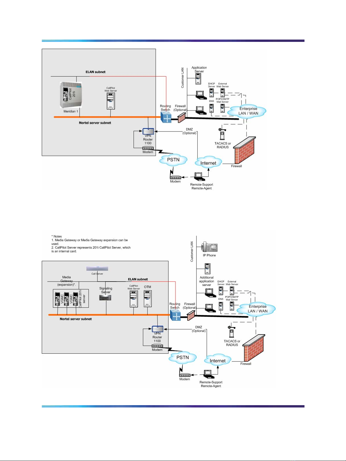
Sample network setup: Meridian 1 switch
The following diagram shows how the 201i server is integrated into your
network with the following Meridian 1 switches:
•
large systems, such as Option 51C
•
Option 11C
• Option 11C Mini
201i Server Hardware Installation
NN44200-301 01.01 Standard
Copyright © 2007, Nortel Networks Nortel Networks Confidential
.
Nortel CallPilot
5.0 15 February 2007
Page 19
Network connectivity 19
Sample network setup: Communication Server 1000
The following diagram shows an example of how the 201i server can be
integrated with the Communication Server 1000 system in your network:
201i Server Hardware Installation
NN44200-301 01.01 Standard
Copyright © 2007, Nortel Networks Nortel Networks Confidential
.
Nortel CallPilot
5.0 15 February 2007
Page 20

20 Chapter 2 About the 201i server
In the illustration on "Sample network setup: Communication Server 1000"
(page 19), the telephony LAN (TLAN) provides IP connectivity between the
Communication Server 1000 system and the i2004 Internet telephones.
The connection between the Call Server and Media Gateway can be
point-to-point, or it can be through the LAN, if the system is installed in
a distributed data network.
For information about the Communication Server 1000 system and i2004
Internet telephone bandwidth and network requirements, refer to the
Communication Server 1000 Planning and Installation Guide
For a description of each Communication Server 1000 system component,
see "Communication Server 1000 description" (page 71).
CallPilot Nortel server subnet and ELAN subnet setup
The 201i server supports the following network protocols:
• CLAN: 10/100Base-T Ethernet
A built-in Ethernet controller on the 201i server motherboard provides
Ethernet connectivity to the Nortel server subnet. The Nortel server
subnet provides data connectivity between desktop and web messaging
clients, administrative PCs, and the CallPilot server.
•
ELAN: 10Base-T Ethernet
A built-in Ethernet controller on the 201i server motherboard provides
Ethernet connectivity to the ELAN subnet. The ELAN subnet carries call
processing traffic between the CallPilot server and the Meridian 1 switch
or Communication Server 1000 system.
Note: For more information about the ELAN subnet, see the
CallPilot Installation and Configuration Task List.
You use the 201i server multi I/O cable to establish the connections to the
ELAN subnet and the Nortel server subnet. For more information, see "Multi
I/O cable description" (page 21).
Network requirements
Appropriate networking equipment must be available for both the Nortel
server subnet and ELAN subnet.
The Nortel server subnet and ELAN subnet must be properly configured
for correct CallPilot operation. To ensure correct configuration, Nortel
recommends that you consult a network specialist.
For important considerations about using the ELAN subnet in your network, see
the CallPilot Installation and Configuration Task List.
ATTENTION
201i Server Hardware Installation
NN44200-301 01.01 Standard
Copyright © 2007, Nortel Networks Nortel Networks Confidential
.
Nortel CallPilot
5.0 15 February 2007
Page 21
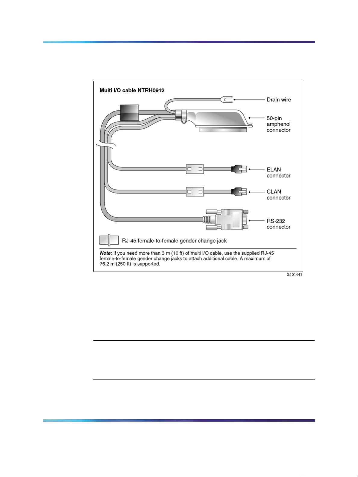
Multi I/O cable description
The multi I/O cable contains four connectors, and is approximately 3 m (10
ft) in length. See the following diagram:
Network connectivity 21
The following table identifies the purpose of each connector on the
NTRH0912 multi I/O cable.
Note: Labels on the RJ-45 cables distinguish the CLAN and ELAN
connectors.
Connector type
50-pin amphenol This connector establishes the connection between
201i Server Hardware Installation
NN44200-301 01.01 Standard
Copyright © 2007, Nortel Networks Nortel Networks Confidential
.
Purpose
the Meridian 1 or Communication Server 1000 Media
Gateway or Media Gateway Expansion backplane,
ELAN and CLAN Ethernet hubs or switches, and
modem.
Nortel CallPilot
5.0 15 February 2007
Page 22

22 Chapter 2 About the 201i server
Connector type
Purpose
10Base-T (RJ-45) This connector provides a 10 Mbit/s Ethernet connection
between the 201i server and the Meridian 1 switch or
Communication Server 1000 system. This connection
allows the exchange of call control information between
the server and the Meridian 1 switch or Communication
Server 1000 system.
For more information about the ELAN subnet, see the
CallPilot Installation and Configuration Task List.
10/100Base-T
(RJ-45)
This connector provides a network connection for
• user desktop computers, to enable use of the
unified messaging and fax messaging features
• LAN-based server administration
ATTENTION
If you need Ethernet 100Base-T operation at 100
Mbit/s on large Meridian 1 systems (such as Option
51), you must install the NTRH3501 backplane (tip
and ring) cable. For more information, see Chapter
4 "Installing the 201i server in a large Meridian 1
system" (page 37).
RS-232 COM1
(male DB-9)
This connector provides the connection to an external
modem. The modem allows administrators and
technical support personnel to administer the 201i
server from a remote location.
Peripheral connectivity
Introduction
Peripheral equipment is attached to the 201i server on the server faceplate.
201i Server Hardware Installation
NN44200-301 01.01 Standard
Copyright © 2007, Nortel Networks Nortel Networks Confidential
.
Nortel CallPilot
5.0 15 February 2007
Page 23

Faceplate connections
Connections made to the faceplate (with the exceptions noted below) are
temporary only, because you must remove the cabinet cover to make these
connections. The system does not meet specifications for radiated EMI if you
remove the cabinet cover.
The following peripheral devices connect to the 201i server faceplate:
•
monitor (SVGA)
•
keyboard
•
mouse
•
MPC card (permanent connection)
•
SCSI cable (permanent connection)
Monitor, keyboard, and mouse
You must connect a monitor, keyboard, and mouse to run the Configuration
Wizard or to install the operating system on the 201i server as part of
a recovery process.
Peripheral connectivity 23
ATTENTION
All three peripheral components are hot-pluggable.
MPC-8 card
The MPC-8 card looks like a Type II PC card, and supports the multimedia
telephony services on the 201i server. Four specially-designed card slots
are available for the MPC-8. All are located on the 201i server faceplate.
ATTENTION
You cannot insert MPC-8 cards in Type II PC card slots, or Type II PC cards into
MPC-8 card slots. They are not compatible.
SCSI connections
The SCSI connection is the only permanent faceplate connection. A
low-profile right-angle connector on the SCSI cable allows the cable to be
attached with the cabinet covers on. For more information about how the
201i server and SCSI device connections are achieved, see:
•
large Meridian 1 systems (for example, Option 51C): "Installing the SCSI
cables for Meridian 1" (page 49).
•
Option 11C or Option 11C Mini: "Installing the NTRH3502 SCSI cable
for Option 11C Mini" (page 63).
•
Communication Server 1000: "Installing the NTRH3502 SCSI cable for
Communication Server 1000" (page 80).
201i Server Hardware Installation
NN44200-301 01.01 Standard
Copyright © 2007, Nortel Networks Nortel Networks Confidential
.
Nortel CallPilot
5.0 15 February 2007
Page 24

24 Chapter 2 About the 201i server
Supported peripheral devices
CD-ROM drive (NTRH9037)
An external CD-ROM drive is used to install and upgrade the server. The
drive connects to the server with an intermediate SCSI cable that connects
to the SCSI connector on the faceplate.
Because the CD-ROM drive is an external device, it requires an AC power
source.
Set the SCSI ID for the CD-ROM drive to 3. If you are connecting more
than one SCSI device to the server (such as a tape drive), you must daisy
chain those devices.
Note: The CD-ROM drive is not hot-pluggable. You must power off the
server to connect or disconnect the drive.
Tape drive (NTRH9038)
An external SCSI tape drive is used to back up and restore data. The device
connects to the server by an intermediate SCSI cable that connects to the
SCSI connector on the faceplate.
Since the tape drive is an external device, it requires an AC power source.
Set the SCSI ID for the tape drive to 5. If you are connecting more than
one SCSI device to the server (such as a CD-ROM drive), you must daisy
chain those devices.
Note: The tape drive is not hot-pluggable. You must power off the
server to connect or disconnect the drive.
Modem
An external modem provides remote access to the 201i server. The modem
connects to the RS-232 COM1 connector on the multi I/O cable.
Since the modem is an external device, it requires its own AC power source.
The supported modem is the 56 Kbps modem (NTRH9078).
10Base-T Ethernet hub or switch
The 10Base-T Ethernet hub provides the ELAN subnet connection between
the 201i server and the Meridian 1 switch or Communication Server 1000
system.
Since the hub or switch is an external device, it requires an AC power source.
201i Server Hardware Installation
NN44200-301 01.01 Standard
Copyright © 2007, Nortel Networks Nortel Networks Confidential
.
Nortel CallPilot
5.0 15 February 2007
Page 25

Peripheral connectivity 25
Monitor, keyboard, and mouse
•
15 in. monitor: NTRH9011 or N0038380 LCD monitor
Since the monitor is an external device, it requires an AC power source.
• Keyboard: NTRH9013
•
Mouse: NTRH9014
Note: The mouse connector on the 201i faceplate is a PS/2 connector.
If you plan to use a USB mouse with USB-to-PS/2 converter, you
must also use the Nortel-supplied 101 mm (4-in) PS/2 extension
cable (A0855616). Without the extension cable, the monitor connector
partially blocks the mouse connector.
201i Server Hardware Installation
NN44200-301 01.01 Standard
Copyright © 2007, Nortel Networks Nortel Networks Confidential
.
Nortel CallPilot
5.0 15 February 2007
Page 26

26 Chapter 2 About the 201i server
201i Server Hardware Installation
Nortel CallPilot
NN44200-301 01.01 Standard
Copyright © 2007, Nortel Networks Nortel Networks Confidential
.
5.0 15 February 2007
Page 27

Chapter 3
Preparing for installation
In this chapter
"Installation overview" (page 27)
"Unpacking and inspecting the 201i server" (page 31)
"Switch and network requirements" (page 33)
Installation overview
Introduction
This section provides a high-level overview of the requirements and
procedure for installing the 201i server.
27
Before you begin
Ensure that proper power and grounding are available for all the power
outlets serving the CallPilot server and its associated peripherals. Power
for these devices must be wired and fused independently of all other
receptacles and referenced to the same ground as the PBX system.
A qualified electrician must implement the single-point ground reference as
required between the power outlets of the CallPilot server and the power
outlets of the switch.
Provide a sufficient number of properly grounded power outlets or power
bars for all equipment.
For more information, refer to Chapter 2, "Grounding and power
requirements", in the CallPilot Planning and Engineering Guide.
201i Server Hardware Installation
NN44200-301 01.01 Standard
Copyright © 2007, Nortel Networks Nortel Networks Confidential
.
Nortel CallPilot
5.0 15 February 2007
Page 28

28 Chapter 3 Preparing for installation
Installation checklist
The following checklist identifies the steps required to install the 201i server
and peripheral devices. For more details, see Chapter 8 "Connecting
peripheral devices to the 201i server" (page 99).
WARNING
Risk of personal injury and hardware failure
The power outlets used by the CallPilot server and its peripheral
devices must be connected to the same ground reference as the
one used by the Meridian 1 switch or Communication Server 1000
system with MGate cards (NTRB18CA) connected to the CallPilot
server. If this requirement is not met, power transients can cause
personal injury and hardware failure.
Step
1
Description
Ensure that you have reviewed the "Installing CallPilot" section in
the CallPilot Installation and Configuration Task List and completed
stage 1 of the "Installation checklist."
This includes the following tasks:
•
Unpack the server, and ensure you have all the items you need
(see "Unpacking and inspecting the 201i server" (page 31)).
Complete the following checklists that are provided in the
CallPilot Installation and Configuration Task List:
— "CallPilot software media and documentation checklist"
— "CallPilot server hardware checklist"
•
Inspect the server for any damage that might have occurred
during shipping (see "Unpacking and inspecting the 201i server"
(page 31)).
Check
2
Familiarize yourself with the "Switch and network requirements"
(page 33) of this guide.
201i Server Hardware Installation
NN44200-301 01.01 Standard
Copyright © 2007, Nortel Networks Nortel Networks Confidential
.
Nortel CallPilot
5.0 15 February 2007
Page 29

Installation overview 29
Step
3
4
Description
If you are installing the 201i server into a Meridian 1 tiered system,
do the following:
•
Change the location of the secondary backplane (DS30X)
connector on the 201i server (see "Repositioning the secondary
backplane connector" (page 39)).
•
Replace the existing backplane (tip and ring) cable on
the Meridian 1 with the one supplied with the 201i server
(NTRH3501) (see pages "Removing the backplane (tip and ring)
cables" (page 43)-"What is next?" (page 49)).
Install the intermediate SCSI cable. This cable connects the external
CD-ROM or tape drive.
•
For Meridian 1, you require two cables to complete the
connection between the 201i server and the SCSI device:
NTRH1408 and NTRH1410. See "Installing the SCSI cables for
Meridian 1" (page 49).
•
For Option 11C, you require two cables to complete the
connection between the 201i server and the SCSI device:
NTRH1407 and NTRH3502. See "Installing the intermediate
SCSI cable for Option 11C" (page 58).
Check
•
For Option 11C Mini or Communication Server 1000, you require
one cable to complete the connection between the 201i server
and the SCSI device: the NTRH3502 cable that is provided in
the CD-ROM and tape drive kits. See the following:
— Option 11C Mini: "Installing the NTRH3502 SCSI cable for
Option 11C Mini" (page 63)
— Communication Server 1000: "Installing the NTRH3502
SCSI cable for Communication Server 1000" (page 80)
5
Set the DIP switches on the modem (see "Setting the modem DIP
switches" (page 90)).
201i Server Hardware Installation
NN44200-301 01.01 Standard
Copyright © 2007, Nortel Networks Nortel Networks Confidential
.
Nortel CallPilot
5.0 15 February 2007
Page 30

30 Chapter 3 Preparing for installation
Step
6
7
Description
Set the following:
•
SCSI IDs on the CD-ROM and tape drives (see pages "Setting
the CD-ROM drive SCSI ID and DIP switches" (page 92) and
"Setting the tape drive SCSI ID" (page 94))
•
DIP switches on the CD-ROM drive (see "Setting the CD-ROM
drive SCSI ID and DIP switches" (page 92))
•
device termination on the CD-ROM and tape drives (see "Setting
SCSI device termination" (page 95))
Insert the 201i server into two consecutive slots inside the switch.
For instructions, see:
•
large Meridian 1 systems, such as Option 51C (see "Installing
the 201i server in the large Meridian 1 switch" (page 42))
•
Option 11C or Option 11C Mini (see "Installing the 201i server in
the Option 11C or Option 11C Mini switch" (page 55))
• Communication Server 1000 (see "Installing the 201i server"
(page 77))
Check
8
Install the MPC cards, if required (see "Installing the MPCs" (page
102)).
9
Connect the 201i server and devices as follows:
•
Connect the monitor, keyboard, and mouse to the 201i server
faceplate (see "Installing the monitor, keyboard, and mouse"
(page 104)).
•
Connect the CD-ROM and tape drives to the intermediate SCSI
cable (see "Connecting the CD-ROM and tape drives" (page
105)).
•
Connect the multi I/O cable to the ELAN and CLAN Ethernet
hubs or switches (see "Connecting the 201i server to the switch,
ELAN subnet , and Nortel server subnet" (page 113)).
Note: If more than 3 m (10 ft) of multi I/O cable is required, use
the supplied RJ-45 female-to-female gender change jacks to attach
additional cable. Up to 76.2 m (250 ft) of cable length is supported.
201i Server Hardware Installation
NN44200-301 01.01 Standard
Copyright © 2007, Nortel Networks Nortel Networks Confidential
.
Nortel CallPilot
5.0 15 February 2007
Page 31

Unpacking and inspecting the 201i server 31
Step
10
Description
•
Connect the modem to the multi I/O cable (maximum length 15
m (50 ft) (see "Connecting the modem" (page 116)).
•
Connect the power cords for all devices, and then power them
up.
Complete the installation of the 201i server as follows:
•
Connect the intermediate SCSI cable to the 201i server
faceplate.
•
Close the lock latches on the 201i server.
•
Boot the 201i server to the operating system.
See "Completing the installation" (page 118).
Check
11
Continue with the CallPilot <switch model> and CallPilot Server
Configuration guide for your switch and server.
Unpacking and inspecting the 201i server
Introduction
This section describes how to:
•
unpack the 201i server and peripherals
•
inspect the 201i server for damage
It also describes what to do if you determine that the 201i server is faulty.
201i Server Hardware Installation
NN44200-301 01.01 Standard
Copyright © 2007, Nortel Networks Nortel Networks Confidential
.
Nortel CallPilot
5.0 15 February 2007
Page 32

32 Chapter 3 Preparing for installation
To unpack the 201i server
Step Action
As you unpack each item, check it off against the packing list, as well as the
following checklists provided in the CallPilot Installation and Configuration Task
List:
•
"CallPilot software media and documentation checklist"
•
"CallPilot server hardware checklist"
ATTENTION
1
2
3
Remove the 201i server from the carton and its antistatic bag.
Place the 201i server on an antistatic surface.
Carefully open the cartons containing the monitor, keyboard, mouse,
modem, and ELAN hub (if supplied), and set the peripherals aside.
4
5
Put all manuals and CD-ROMs in a safe place.
Save all packing materials and cartons in case you must return any
equipment to the carrier.
6
Review "201i server description" (page 11), and perform a visual
inspection as described in "To inspect the 201i server for shipping
damage" (page 32).
—End—
To inspect the 201i server for shipping damage
Before proceeding with the installation, visually inspect the 201i server for
any damage that might have occurred during shipping. Ensure also that the
items in the following checklists are secure:
Item Yes No
Are all cables securely seated?
•
hard drive power cable
•
hard drive data cable
201i Server Hardware Installation
NN44200-301 01.01 Standard
Copyright © 2007, Nortel Networks Nortel Networks Confidential
.
Nortel CallPilot
5.0 15 February 2007
Page 33

Switch and network requirements 33
Item Yes No
See items 2 and 3 in the diagram on page 15.
Is the hard drive and bracket interface secure? See items 6
and 7 in the diagram on page 15.
Is the software feature key (dongle) securely seated in its
bracket?
See 201i server components diagram on page 15.
What to do if components are missing or damaged
IF THEN
you observe any damage contact your Nortel technical support
representative.
components have become loose secure them.
you are satisfied that the 201i
server has arrived at your site
undamaged
What is next?
Review the "Switch and network requirements" (page 33).
Switch and network requirements
Introduction
The information in this section will help you plan your 201i serverinstallation.
Meridian 1 or Communication Server 1000 slot requirements
The 201i server occupies two physical and electrical slots.
If necessary, refer to the procedures
in the CallPilot <server model> Server
Maintenance and Diagnostics guide for
your server.
you are ready to proceed with installation.
Note: You can place the unit in Slot 9 of an Option11C as the unit can
function from slots 9 and 10. Do not place the unit in slot 10. Even
201i Server Hardware Installation
NN44200-301 01.01 Standard
Copyright © 2007, Nortel Networks Nortel Networks Confidential
.
Nortel CallPilot
5.0 15 February 2007
Page 34

34 Chapter 3 Preparing for installation
though the unit can physically fit, there is no electrical connection on
the backplane to slot 11.
You must install the 201i server in two peripheral equipment slots as follows:
Switch Slots
Meridian 1 tiered
systems
Option 11C 1 through 9 in any Option 11C cabinet
Option 11C Mini A pair of consecutive slots in any cabinet
Communication
Server 1000
0 through 14
Ensure that both slots have electrical backplane
connectivity.
Note: You cannot install the 201i server in slots 0 or 4
because these slots are dedicated to other cards. For
more information about cards and slots, refer to the
Option 11C Mini documentation.
A pair of consecutive slots in any Media Gateway or
Media Gateway Expansion.
Note: The 201i server cannot be installed in slots 0 or
4, because these slots are dedicated to other cards.
For more information about cards and slots, refer to the
Communication Server 1000 Planning and Installation
Guide
Meridian 1 I/O panel connections
On large Meridian 1 systems (such as Option 51C), the 201i server requires
two connections from the slots to the I/O panel on the rear of the switch, as
follows:
•
One connection is for the multi I/O cable.
This connection corresponds to the left slot (when viewing the front
of the Meridian 1 switch).
•
The other connection is for the external SCSI device.
This connection corresponds to the right slot (when viewing the front
of the Meridian 1 switch).
201i Server Hardware Installation
NN44200-301 01.01 Standard
Copyright © 2007, Nortel Networks Nortel Networks Confidential
.
Nortel CallPilot
5.0 15 February 2007
Page 35

Switch and network requirements 35
For information about slot and rear bulkhead wiring, refer to the Meridian 1
System Installation and Maintenance Guide
Nortel server subnet and ELAN subnet requirements
The ELAN subnet and the Nortel server subnet must be configured and the
appropriate networking equipment must be available.
If the Nortel server subnet is to be part of the customer LAN, you need a
network specialist to ensure proper configuration.
ATTENTION
For important considerations about using the ELAN in your network, see
theCallPilot Installation and Configuration Task List.
What is next?
Install the 201i server in the Meridian 1 switch or Communication Server
1000 system. For instructions, see one of the following:
To install the 201i server in
a large Meridian 1 switch (for example,
Option 51C)
an Option 11C or Option 11C Mini
switch
the Communication Server 1000
system
See
Chapter 4 "Installing the 201i server in
a large Meridian 1 system" (page 37)
Chapter 5 "Installing the 201i server
in an Option 11C or Option 11C Mini"
(page 55)
Chapter 6 "Installing the 201i server
in the Communication Server 1000
system" (page 71)
201i Server Hardware Installation
NN44200-301 01.01 Standard
Copyright © 2007, Nortel Networks Nortel Networks Confidential
.
Nortel CallPilot
5.0 15 February 2007
Page 36

36 Chapter 3 Preparing for installation
201i Server Hardware Installation
Nortel CallPilot
NN44200-301 01.01 Standard
Copyright © 2007, Nortel Networks Nortel Networks Confidential
.
5.0 15 February 2007
Page 37

Chapter 4
Installing the 201i server in a large
Meridian 1 system
in this chapter
"Overview" (page 37)
"Repositioning the secondary backplane connector" (page 39)
"Installing the 201i server in the large Meridian 1 switch" (page 42)
"Removing the backplane (tip and ring) cables" (page 43)
"Installing the NTRH3501 backplane cable" (page 47)
37
"Installing the SCSI cables for Meridian 1" (page 49)
Overview
Introduction
This section describes how to install the 201i server in a Meridian 1 switch.
ATTENTION
To install the 201i server in an Option 11C, go to "Installing the 201i server in
the large Meridian 1 switch" (page 42). For Option 11C Mini, go to "Section B:
Installing Option 11C Mini cables" (page 63). For Communication Server 1000,
go to Chapter 6 "Installing the 201i server in the Communication Server 1000
system" (page 71).
Meridian 1 I/O panel connections
On the Meridian 1, the 201i server requires two connections from the slots
to the I/O panel on the rear of the switch, as follows:
• One connection is for the multi I/O cable.
201i Server Hardware Installation
NN44200-301 01.01 Standard
Copyright © 2007, Nortel Networks Nortel Networks Confidential
.
Nortel CallPilot
5.0 15 February 2007
Page 38

38 Chapter 4 Installing the 201i server in a large Meridian 1 system
This connection corresponds to the left slot (when viewing the front
of the Meridian 1 switch).
•
The other connection is for the external SCSI device.
This connection corresponds to the right slot (when viewing the front
of the Meridian 1 switch).
For information about slot and rear bulkhead wiring, refer to the Meridian 1
System Installation and Maintenance Guide
Secondary backplane connector
The secondary backplane (DS30X) connector on the 201i server connects
the server to the second slot on the shelf, thereby providing access to the
voice channels provided by that slot.
CAUTION
Risk of equipment damage
The 201i server is shipped ready for installation into an Option
11C switch. Before you install the 201i server in a larger Meridian
1 switch (for example, Option 51C), you must move the secondary
backplane (DS30X) connector to the correct position.
A yellow warning label over the top lock latch on the 201i server prevents you
from securing the 201i server in a slot. This label serves as a reminder to move
the secondary backplane connector to the Meridian 1 position, if required, before
installing the 201i server into the slot.
Backplane (tip and ring) cable
The backplane (tip and ring) cable supplied with the 201i server(NTRH3501)
provides 100Base-T Ethernet operation for the Nortel server subnet. This
cable offers more network throughput than the cable that is already installed
on the Meridian 1.
When installed, this cable completes the connection between the left slot,
the I/O panel on the rear of the switch, and the multi I/O cable on the 201i
server.
SCSI cables
Before you can connect a CD-ROM or tape drive to the 201i server, you
must install the SCSI cables. You require two cables. These cables route
the SCSI connection away from the 201i server faceplate so that an external
SCSI device can remain permanently connected.
ATTENTION
201i Server Hardware Installation
NN44200-301 01.01 Standard
Copyright © 2007, Nortel Networks Nortel Networks Confidential
.
Nortel CallPilot
5.0 15 February 2007
Page 39

Repositioning the secondary backplane connector 39
Repositioning the secondary backplane connector
Introduction
The secondary backplane (DS30X) connector on the 201i server connects
the server to the second slot on the shelf, thereby providing access to the
voice channels provided by that slot.
CAUTION
Risk of equipment damage
The 201i server ships ready for installation into an Option 11C
or Option 11C Mini switch. Before you install the 201i server in
a larger Meridian 1 switch (for example, Option 51C), you must
move the secondary backplane (DS30X) connector to the correct
position.
Why you must move the connector
There is an approximate difference of 2 mm (0.08 in) between slots on a
Meridian 1 tiered system and an Option 11C or Option 11C Mini system. As
a result, you must install the secondary backplane (DS30X) connector on
the 201i server in the correct position before a successful connection with
the switch backplane can be established.
ATTENTION
A yellow warning label over the top lock latch on the 201i server prevents you
from securing the 201i server in a slot. This label serves as a reminder to move
the secondary backplane connector to the Meridian 1 position, if required, before
installing the 201i server into the slot.
Secondary backplane connector description
The secondary backplane connector is attached to the backplane edge of
the 201i server. It consists of the following items:
•
connector
•
screws
• pin connector (with four pins)
Two pairs of screw holes are provided for connecting the secondary
backplane connector to the 201i server stiffening cage. The outside pair
provides the Meridian 1 spacing. The inside pair provides the Option 11C or
Option 11C Mini spacing.
See the following diagram:
201i Server Hardware Installation
NN44200-301 01.01 Standard
Copyright © 2007, Nortel Networks Nortel Networks Confidential
.
Nortel CallPilot
5.0 15 February 2007
Page 40

40 Chapter 4 Installing the 201i server in a large Meridian 1 system
Required equipment
To move the secondary backplane connector, you need a Phillips No. 1
screwdriver. A pair of needle-nosed pliers can also be helpful for removing
the pin connector.
To prepare the 201i server for installation in a Meridian 1 switch
Step Action
1
2
3
4
Copyright © 2007, Nortel Networks Nortel Networks Confidential
.
Remove the secondary backplane pin connector.
The pin connector has four pins. If necessary, use needle-nosed
pliers to remove it.
Remove the top and bottom screws that hold the secondary
backplane connector in place on the stiffening cage.
Loosen the middle screw, and then align the outside pair of screw
holes on the bracket with the matching pair on the stiffening cage.
Replace and alternately tighten all screws until the connector is
evenly and securely fastened.
Nortel CallPilot
201i Server Hardware Installation
NN44200-301 01.01 Standard
5.0 15 February 2007
Page 41

Repositioning the secondary backplane connector 41
See the following diagram:
5
Replace the pin connector so the pins protrude through both
connectors.
Ensure that the connectors are correctly aligned as shown in the
diagram below.
201i Server Hardware Installation
NN44200-301 01.01 Standard
Copyright © 2007, Nortel Networks Nortel Networks Confidential
.
Nortel CallPilot
5.0 15 February 2007
Page 42

42 Chapter 4 Installing the 201i server in a large Meridian 1 system
CAUTION
Risk of equipment damage
6
Gently press the pin connector into the socket until it is fully seated.
7 Remove the yellow backplane warning label from the top lock latch
on the 201i server.
—End—
What is next?
Continue with "Installing the 201i server in the large Meridian 1 switch"
(page 42).
Installing the 201i server in the large Meridian 1 switch
Introduction
The 201i server occupies two slots. You can install the 201i server in slots 0
through 14. Ensure that both slots have electrical backplane connectivity.
201i Server Hardware Installation
NN44200-301 01.01 Standard
Copyright © 2007, Nortel Networks Nortel Networks Confidential
.
Nortel CallPilot
5.0 15 February 2007
Page 43

Removing the backplane (tip and ring) cables 43
To position the 201i server on the switch shelf
Step Action
1
Ensure that no cables are connected to the slots in which you are
installing the 201i server.
2
Open the lock latches at the top and bottom of the 201i server
faceplate.
Note: When you open the top lock latch, you break the yellow
backplane warning label, if it has not been removed. You must
move the secondary backplane connector before you install
the 201i server. For details, see "Repositioning the secondary
backplane connector" (page 39).
3
Slide the 201i server into an unoccupied pair of slots.
Ensure that the 201i server is positioned correctly between the slots.
ATTENTION
Do not push the 201i server into place against the backplane until you are
ready to observe the startup cycle.
The 201i server receives power and starts as soon as the 201i server
makes contact with the switch backplane.
4
Connect the low-profile right-angle SCSI cable connector to the
SCSI connector on the 201i server faceplate.
—End—
What is next?
Continue with "Removing the backplane (tip and ring) cables" (page 43).
Removing the backplane (tip and ring) cables
Introduction
You must remove the Meridian 1 backplane (tip and ring) cables that are
associated with the slots occupied by the 201i server so that you can install
the following cables:
•
NTRH3501 backplane (tip and ring) cable
The NTRH3501 cable offers more network throughput than the cable
that is already installed on the Meridian 1. This cable is connected to
the backplane connectors and I/O panel slot associated with the left slot.
• NTRH1408 intermediate SCSI cable
201i Server Hardware Installation
NN44200-301 01.01 Standard
Copyright © 2007, Nortel Networks Nortel Networks Confidential
.
Nortel CallPilot
5.0 15 February 2007
Page 44

44 Chapter 4 Installing the 201i server in a large Meridian 1 system
The NTRH1408 intermediate SCSI cable routes the SCSI device
connection away from the 201i server faceplate so that an external SCSI
device can remain permanently connected. This cable is connected to
the I/O panel only. The backplane connectors associated with the right
slot are left vacant.
These cables are supplied with the 201i server.
Before you begin
DANGER
Risk of electrical shock
Ensure that the shelf is powered off before you remove the
backplane cables.
Note: For information about slot and rear bulkhead wiring and powering
off the shelf, refer to the Meridian 1 System Installation and Maintenance
Guide
To remove the backplane cables
Step Action
1
2
Remove the I/O panel cover from the rear of the Meridian 1 switch.
Remove the protective plate from the rear of the Meridian 1 switch.
201i Server Hardware Installation
NN44200-301 01.01 Standard
Copyright © 2007, Nortel Networks Nortel Networks Confidential
.
Nortel CallPilot
5.0 15 February 2007
Page 45

Removing the backplane (tip and ring) cables 45
3
Remove the existing backplane cable, including the I/O filter
assembly (NT8D81xx) and mounting hardware for the left slot as
follows:
a. Remove the external cable attached to the outside of the I/O
panel.
b. For each of the UP 1, UP 2, and UP 3 cable connectors, push
the lock tab outwards to unlock the cable connection, and then
pull the connector off.
ATTENTION
If you attempt to pull the connector off without pressing the lock tab,
you can pull the connector shroud off the backplane. If this happens,
refer to the adjacent connectors for correct key positioning, and then
replace the connector shroud.
Remove the tie wraps where applicable to free the cable.
c. Remove the connector, I/O filter assembly, and all mounting
hardware from the inside of the I/O panel so the slot is completely
vacated.
Retain the mounting hardware (that is, screws, tie wrap base,
standoffs, and so on). You will reuse this hardware to fasten the
NTRH3501 cable.
201i Server Hardware Installation
NN44200-301 01.01 Standard
Copyright © 2007, Nortel Networks Nortel Networks Confidential
.
Nortel CallPilot
5.0 15 February 2007
Page 46

46 Chapter 4 Installing the 201i server in a large Meridian 1 system
4
Repeat step 3 to remove the existing backplane cable for the right
slot.
Store the cable, I/O filter assembly, and mounting hardware for this
cable with your Meridian 1 spares. You will not use them with the
201i server.
The following diagram shows an example using slots 3 and 4:
—End—
What is next?
Continue with "Installing the NTRH3501 backplane cable" (page 47).
201i Server Hardware Installation
NN44200-301 01.01 Standard
Copyright © 2007, Nortel Networks Nortel Networks Confidential
.
Nortel CallPilot
5.0 15 February 2007
Page 47

Installing the NTRH3501 backplane cable 47
Installing the NTRH3501 backplane cable
Introduction
You must connect the backplane (tip and ring) cable supplied with the 201i
server (NTRH3501) for 100Base-T Ethernet operation to the Nortel server
subnet. This cable offers more network throughput than the cable you just
removed from the Meridian 1.
When installed, this cable completes the connection between the left slot,
the I/O panel on the rear of the switch, and the multi I/O cable on the 201i
server.
Backplane (tip and ring) cable
The following diagram shows the NTRH3501 backplane (tip and ring) cable:
Before you begin
Before you can install the NTRH3501 cable, you must remove the existing
backplane cable from the back of the switch. See "Removing the backplane
(tip and ring) cables" (page 43).
201i Server Hardware Installation
NN44200-301 01.01 Standard
Copyright © 2007, Nortel Networks Nortel Networks Confidential
.
Nortel CallPilot
5.0 15 February 2007
Page 48

48 Chapter 4 Installing the 201i server in a large Meridian 1 system
To install the NTRH3501 backplane cable
Step Action
1
Install and connect the NTRH3501 cable to the multi I/O cable as
follows:
a. Attach the backplane connector of the NTRH3501 cable to the
inside of the I/O panel slot associated with the 201i server left
slot.
Insert the original screw into the tie wrap base and fasten the
screw into the lower position of the I/O panel slot.
b. Attach the three inner cables to the backplane connectors
associated with the left slot as follows:
•
UP 1 cable to the top position
•
UP 2 cable to the middle position
• UP 3 cable to the lower position
ATTENTION
The connectors are keyed; you can insert them in one position only.
Use tie wraps to secure the cables in their original positions.
c. Connect the 50-pin amphenol connector on the multi I/O cable
(NTRH0912) to the NTRH3501 backplane cable connector on
the I/O panel.
—End—
See the following diagram:
201i Server Hardware Installation
NN44200-301 01.01 Standard
Copyright © 2007, Nortel Networks Nortel Networks Confidential
.
Nortel CallPilot
5.0 15 February 2007
Page 49

Installing the SCSI cables for Meridian 1 49
What is next?
Continue with "Installing the SCSI cables for Meridian 1" (page 49).
Installing the SCSI cables for Meridian 1
Introduction
Before you can connect a CD-ROM or tape drive to the 201i server, you
must install the SCSI cables. The SCSI cables route the SCSI connection
away from the 201i server faceplate so that an external SCSI device can
remain permanently connected.
CAUTION
Risk of equipment damage
You must power off the 201i server before connecting or
disconnecting SCSI cables.
201i Server Hardware Installation
NN44200-301 01.01 Standard
Copyright © 2007, Nortel Networks Nortel Networks Confidential
.
Nortel CallPilot
5.0 15 February 2007
Page 50

50 Chapter 4 Installing the 201i server in a large Meridian 1 system
Cables you need
You require the following cables:
•
NTRH1408 (for connecting the 201i server to the Meridian 1 I/O panel)
The connector on the intermediate SCSI cable that attaches to the 201i
server faceplate is a low-profile right-angle connector. This allows the
cable to be attached with the Meridian 1 cabinet cover on.
•
NTRH1410 (for connecting an external SCSI device to the NTRH1408
connector on the Meridian 1 I/O panel)
The total length of the cable from the I/O panel is 4.1 m (13.3 ft).
What the completed installation looks like
The following diagram shows how the intermediate SCSI cable, CD-ROM
drive, and tape drive are connected to the Meridian 1.
In this diagram, the CD-ROM drive is the first device. The tape drive is
the last device.
201i Server Hardware Installation
NN44200-301 01.01 Standard
Copyright © 2007, Nortel Networks Nortel Networks Confidential
.
Nortel CallPilot
5.0 15 February 2007
Page 51

Installing the SCSI cables for Meridian 1 51
Note: Alternate SCSI device connection scenarios are supported, but
are not depicted in this guide. If you want to use a connection scenario
that is not described in this guide, ensure that you use appropriate
cabling for each device.
Before you begin
Before you install the SCSI devices in a daisy chain, you must configure the
SCSI device IDs and DIP switches. For instructions, refer to Chapter 7
"Preparing peripheral devices" (page 89).
To install the SCSI cables for Meridian 1
Step Action
1 Thread the SCSI connector end of the NTRH1408 cable from the
front of the Meridian 1 along the bottom of the shelf to either the
left or the right access channel.
2
Leave the low-profile right-angle SCSI connector hanging for now.
You will connect it later to the 201i server faceplate.
Note: The following diagram shows what the connection looks
like after the cable is connected:
201i Server Hardware Installation
NN44200-301 01.01 Standard
Copyright © 2007, Nortel Networks Nortel Networks Confidential
.
Nortel CallPilot
5.0 15 February 2007
Page 52

52 Chapter 4 Installing the 201i server in a large Meridian 1 system
3
Thread the cable through the access channel to the back of the
Meridian 1.
4
Attach the NTRH1408 cable to the inside of the I/O panel slot
associated with the 201i server right slot.
5
Connect the NTRH1410 cable to the NTRH1408 cable connector on
the I/O panel.
See the following diagram:
201i Server Hardware Installation
NN44200-301 01.01 Standard
Copyright © 2007, Nortel Networks Nortel Networks Confidential
.
Nortel CallPilot
5.0 15 February 2007
Page 53

Installing the SCSI cables for Meridian 1 53
Note: The backplane connectors for the right slot are not
required and, therefore, are left vacant.
6
Thread the NTRH1410 cable through the shelves below and out
through the bottom of the Meridian 1 tower.
7
8
9
Replace the protective plate.
Replace the I/O panel cover.
Power up the shelf.
—End—
What is next?
Prepare the modem, CD-ROM drive, and tape drive for connection to the
201i server. For instructions, see Chapter 7 "Preparing peripheral devices"
(page 89).
201i Server Hardware Installation
NN44200-301 01.01 Standard
Copyright © 2007, Nortel Networks Nortel Networks Confidential
.
Nortel CallPilot
5.0 15 February 2007
Page 54

54 Chapter 4 Installing the 201i server in a large Meridian 1 system
201i Server Hardware Installation
Nortel CallPilot
NN44200-301 01.01 Standard
Copyright © 2007, Nortel Networks Nortel Networks Confidential
.
5.0 15 February 2007
Page 55

Chapter 5
Installing the 201i server in an Option
11C or Option 11C Mini
In this chapter
"Installing the 201i server in the Option 11C or Option 11C Mini switch"
(page 55)
"Section A: Installing Option 11C cables" (page 58)
"Installing the intermediate SCSI cable for Option 11C" (page 58)
"Section B: Installing Option 11C Mini cables" (page 63)
"Installing the NTRH3502 SCSI cable for Option 11C Mini" (page 63)
55
"Installing cables on the back of the Option 11C Mini cabinet" (page 68)
Installing the 201i server in the Option 11C or Option 11C Mini switch
Introduction
The 201i server occupies physical and electrical slots. The 201i server must
be installed in two peripheral equipment slots as follows:
Switch
Option 11C Slots 1 through 9 in any cabinet
Option 11C Mini A pair of consecutive slots in any cabinet
201i Server Hardware Installation
NN44200-301 01.01 Standard
Copyright © 2007, Nortel Networks Nortel Networks Confidential
.
Nortel CallPilot
5.0 15 February 2007
Eligible slots
Note: You cannot install the 201i server in
slots 0 or 4, because these slots are dedicated
to other cards. For more information about
cards and slots, refer to the Option 11C Mini
documentation.
Page 56

56 Chapter 5 Installing the 201i server in an Option 11C or Option 11C Mini
To position the 201i server on the switch shelf
Step Action
1
Remove the front panel of the switch.
Note: On the Option 11C Mini, do the following:
a. Loosen the spring-loaded clips.
b. Slide the cover to the left.
c. Pull the cover up to remove it from the cabinet.
See the following diagram:
2
Ensure that no cables are connected to the slots in which you are
installing the 201i server.
3
Open the lock latches at the top and bottom of the 201i server
faceplate.
201i Server Hardware Installation
NN44200-301 01.01 Standard
Copyright © 2007, Nortel Networks Nortel Networks Confidential
.
Nortel CallPilot
5.0 15 February 2007
Page 57

Installing the 201i server in the Option 11C or Option 11C Mini switch 57
Note: When you open the top lock latch, it breaks the yellow
backplane warning label, if the label has not been removed. The
label is not relevant for Option 11C or Option 11C Mini. Remove
the label and continue with this procedure.
4
Slide the 201i server into an unoccupied pair of slots.
Ensure that the 201i server is positioned correctly between the slots.
Note: When correctly inserted in the Option 11C Mini, the top of
the 201i server is on the left. See the following diagram:
ATTENTION
Do not push the 201i server into place against the backplane until you are
ready to observe the startup cycle.
The 201i server receives power and starts as soon as the 201i server
makes contact with the switch
backplane.
201i Server Hardware Installation
NN44200-301 01.01 Standard
Copyright © 2007, Nortel Networks Nortel Networks Confidential
.
Nortel CallPilot
5.0 15 February 2007
Page 58

58 Chapter 5 Installing the 201i server in an Option 11C or Option 11C Mini
—End—
What is next?
Continue with installing the cables. Refer to one of the following:
•
"Section A: Installing Option 11C cables" (page 58)
•
"Section B: Installing Option 11C Mini cables" (page 63)
Section A: Installing Option 11C cables
In this section
"Installing the intermediate SCSI cable for Option 11C" (page 58)
Installing the intermediate SCSI cable for Option 11C
Introduction
Before you can connect an external CD-ROM or tape drive to the 201i
server, Option 11C requires an intermediate SCSI cable (NTRH1407).
Note: If you are installing the 201i server in an Option 11C Mini, go to
"Installing the NTRH3502 SCSI cable for Option 11C Mini" (page 63).
Cable description
The connector on the NTRH1407 cable that attaches to the 201i server
faceplate is a low-profile right-angle connector. This allows the SCSI device
to be permanently connected to the 201i server with the Option 11C cabinet
cover on.
The SCSI device connector end is equipped with a bracket assembly.
This bracket assembly attaches to the Option 11C below the card cage.
The CD-ROM or tape drive connects to this bracket assembly with the
NTRH3502 cable that is provided with the device.
201i Server Hardware Installation
NN44200-301 01.01 Standard
Copyright © 2007, Nortel Networks Nortel Networks Confidential
.
Nortel CallPilot
5.0 15 February 2007
Page 59

Installing the intermediate SCSI cable for Option 11C 59
What the completed installation looks like
The following diagram shows how the intermediate SCSI cable, CD-ROM
drive, and tape drive are connected to the Option 11C. The CD-ROM drive
is the first device. The tape drive is the last device.
201i Server Hardware Installation
NN44200-301 01.01 Standard
Copyright © 2007, Nortel Networks Nortel Networks Confidential
.
Nortel CallPilot
5.0 15 February 2007
Page 60

60 Chapter 5 Installing the 201i server in an Option 11C or Option 11C Mini
Note: Alternate SCSI device connection scenarios are supported, but
are not depicted in this guide. If you want to use a connection scenario
that is not described in this guide, ensure that you use appropriate
cabling for each device.
Before you begin
Before you install the SCSI devices in a daisy chain, you must configure
the SCSI device IDs and DIP switches. For instructions, see Chapter 7
"Preparing peripheral devices" (page 89).
To install the cable
Step Action
1
Attach the bracket assembly and cable as follows:
a. Below the card cage, temporarily remove the hardware that
CAUTION
Risk of equipment damage
You must power off the 201i server before connecting or
disconnecting SCSI cables.
secures cable connections to the Option 11C.
201i Server Hardware Installation
NN44200-301 01.01 Standard
Copyright © 2007, Nortel Networks Nortel Networks Confidential
.
Nortel CallPilot
5.0 15 February 2007
Page 61

Installing the intermediate SCSI cable for Option 11C 61
b. Temporarily remove any cabling that may interfere with the
installation of the intermediate SCSI cable bracket assembly.
ATTENTION
Before you disconnect the cabling, take the telephony equipment
services associated with the cabling out of service.
c. Remove the two screws on the right side of the Option 11C I/O
panel.
d. Attach the intermediate SCSI cable bracket assembly, using the
screws that were removed previously, so that the SCSI connector
appears on the right side of the Option 11C cabinet.
See the following diagram:
2 Thread the cable up through the card cage.
201i Server Hardware Installation
NN44200-301 01.01 Standard
Copyright © 2007, Nortel Networks Nortel Networks Confidential
.
Nortel CallPilot
5.0 15 February 2007
Page 62

62 Chapter 5 Installing the 201i server in an Option 11C or Option 11C Mini
Note: When routing the SCSI cable through the card cage,
ensure the second cable ferrite is placed halfway through the
opening.
3
Connect the grounding braid on the intermediate SCSI cable to the
card cage, and tighten the screw.
4
Leave the low-profile right-angle SCSI connector loose for now. You
will connect it later to the 201i server faceplate.
Note: The following diagram shows what the connection looks
like after the cable is connected:
5
6
Replace all cabling and hardware that you removed in Step 1.
Restore any services that you took out of service in Step 1.
—End—
201i Server Hardware Installation
NN44200-301 01.01 Standard
Copyright © 2007, Nortel Networks Nortel Networks Confidential
.
Nortel CallPilot
5.0 15 February 2007
Page 63

Installing the NTRH3502 SCSI cable for Option 11C Mini 63
What is next?
Prepare the modem, CD-ROM drive, and tape drive for connection to the
201i server. For instructions, see Chapter 7 "Preparing peripheral devices"
(page 89).
Section B: Installing Option 11C Mini cables
In this section
"Installing the NTRH3502 SCSI cable for Option 11C Mini" (page 63)
"Installing cables on the back of the Option 11C Mini cabinet" (page 68)
Installing the NTRH3502 SCSI cable for Option 11C Mini
Introduction
Before you can connect a CD-ROM or tape drive to the 201i server, you
must install the NTRH3502 SCSI cable. The NTRH3502 SCSI cable routes
the SCSI connection away from the 201i server faceplate so that an external
SCSI device can remain permanently connected.
If the Option 11C Mini is equipped with a Fiber Routing Guide (consisting of
a spool and mounting bracket), you must remove it before you can install the
NTRH3502 SCSI cable, and then reinstall it when you are finished.
For detailed instructions on removing and installing the Fiber Routing Guide,
refer to the Option 11C and Option 11C Mini Expansion Guide
What the completed installation looks like
The following diagram shows how the intermediate SCSI cable, CD-ROM
drive, and tape drive are connected to the Option 11C Mini. In the diagram,
the CD-ROM drive is the first device. The tape drive is the last device.
201i Server Hardware Installation
NN44200-301 01.01 Standard
Copyright © 2007, Nortel Networks Nortel Networks Confidential
.
Nortel CallPilot
5.0 15 February 2007
Page 64

64 Chapter 5 Installing the 201i server in an Option 11C or Option 11C Mini
Note: Alternate SCSI device connection scenarios are supported, but
are not depicted in this guide. If you want to use a connection scenario
that is not described in this guide, ensure that you use appropriate
cabling for each SCSI device.
Before you begin
1. Before you install the SCSI devices in a daisy chain, you must configure
the SCSI device IDs and DIP switches.
Forinstructions, see Chapter 7 "Preparing peripheral devices" (page 89).
To install the NTRH3502 SCSI cable
Step Action
1
If your Option 11C Mini is equipped with a Fiber Routing Guide,
temporarily remove it.
CAUTION
Risk of equipment damage
You must power off the 201i server before connecting or
disconnecting SCSI cables.
Note: For detailed instructions, refer to the Option 11C and
Option 11C Mini Expansion Guide
201i Server Hardware Installation
NN44200-301 01.01 Standard
Copyright © 2007, Nortel Networks Nortel Networks Confidential
.
Nortel CallPilot
5.0 15 February 2007
Page 65

Installing the NTRH3502 SCSI cable for Option 11C Mini 65
See the following diagram:
2
Remove the inner SCSI bracket from the inside of the cabinet.
See the following diagram:
201i Server Hardware Installation
NN44200-301 01.01 Standard
Copyright © 2007, Nortel Networks Nortel Networks Confidential
.
Nortel CallPilot
5.0 15 February 2007
Page 66

66 Chapter 5 Installing the 201i server in an Option 11C or Option 11C Mini
3
Refasten the inner SCSI bracket screws in their original locations
inside the cabinet.
You will use the top screw later to fasten the NTRH3502 SCSI cable
drain wire.
4
Connect the low-profile right-angle SCSI connector on the
NTRH3502 cable to the SCSI connector on the 201i serverfaceplate.
5
Fasten the SCSI cable drain wire to the top screw that previously
held the inner SCSI bracket in place.
201i Server Hardware Installation
NN44200-301 01.01 Standard
Copyright © 2007, Nortel Networks Nortel Networks Confidential
.
Nortel CallPilot
5.0 15 February 2007
Page 67

Installing the NTRH3502 SCSI cable for Option 11C Mini 67
SCSI cable installation to accommodate the Fiber Routing Guide
6
If required, reinstall the Fiber Routing Guide.
Note: For detailed instructions, refer to the Option 11C and
Option 11C Mini Expansion Guide
See the following diagram:
201i Server Hardware Installation
NN44200-301 01.01 Standard
Copyright © 2007, Nortel Networks Nortel Networks Confidential
.
Nortel CallPilot
5.0 15 February 2007
Page 68

68 Chapter 5 Installing the 201i server in an Option 11C or Option 11C Mini
7
Replace the cabinet cover.
—End—
What is next?
Continue with "Installing cables on the back of the Option 11C Mini cabinet"
(page 68).
Installing cables on the back of the Option 11C Mini cabinet
Introduction
The following items connect to the back of the Option 11C Mini cabinet:
•
multi I/O cable (NTRH0912)
•
Option 11C Mini power cord with two ferrites
You must connect the multi I/O cable first before connecting the power cord,
because the power cord routes over the multi I/O cable connection.
201i Server Hardware Installation
NN44200-301 01.01 Standard
Copyright © 2007, Nortel Networks Nortel Networks Confidential
.
Nortel CallPilot
5.0 15 February 2007
Page 69

Installing cables on the back of the Option 11C Mini cabinet 69
To connect the cables
Step Action
1
On the rear of the Option 11C Mini cabinet, locate the connector
associated with the first slot occupied by the 201i server.
2
Connect the NTRH0912 multi I/O cable as follows:
a. Loosen the connector’s Velcro fastening strap.
b. Connect the amphenol connector on the NTRH0912 multi I/O
cable to the connector on the back of the Option 11C Mini
cabinet.
c. Secure the connection by tightening the retaining screw and
Velcro fastening strap of the connector.
The following diagram shows how to secure the multi I/O cable
connection:
3
Attach the multi I/O cable drain wire to a screw on the cabinet.
See the diagram in step 4.
4
Connect the power cord to the Option 11C Mini cabinet.
See the following diagram:
201i Server Hardware Installation
NN44200-301 01.01 Standard
Copyright © 2007, Nortel Networks Nortel Networks Confidential
.
Nortel CallPilot
5.0 15 February 2007
Page 70

70 Chapter 5 Installing the 201i server in an Option 11C or Option 11C Mini
—End—
What is next?
Prepare the modem, CD-ROM drive, and tape drive for connection to the
201i server. For instructions, see Chapter 7 "Preparing peripheral devices"
(page 89).
201i Server Hardware Installation
NN44200-301 01.01 Standard
Copyright © 2007, Nortel Networks Nortel Networks Confidential
.
Nortel CallPilot
5.0 15 February 2007
Page 71

Chapter 6
Installing the 201i server in the
Communication Server 1000 system
In this chapter
"Communication Server 1000 description" (page 71)
"Removing the Media Gateway or Media Gateway Expansion cover" (page
75)
"Installing the 201i server" (page 77)
"Installing the NTRH3502 SCSI cable for Communication Server 1000"
(page 80)
71
"Replacing the Media Gateway or Media Gateway Expansion cover" (page
82)
"Connecting cables to the Communication Server 1000 system" (page 85)
Communication Server 1000 description
Introduction
The Communication Server 1000 system is an IP PBX that provides
telephony and data capabilities over an IP network. The Communication
Server 1000 system consists of the following major components:
•
Call Server
•
Media Gateway
• Media Gateway Expansion
Call Server
The Call Server provides telephony services and call processing.
201i Server Hardware Installation
NN44200-301 01.01 Standard
Copyright © 2007, Nortel Networks Nortel Networks Confidential
.
Nortel CallPilot
5.0 15 February 2007
Page 72

72 Chapter 6 Installing the 201i server in the Communication Server 1000 system
It supports up to four Media Gateways and four Media Gateway Expansions
when the Small System Controller (SSC) card inside the unit is fully
populated with two dual-port 100BaseT daughterboards.
The following connectors are located on the back of the Call Server:
•
four 100Base-T connectors for connecting Media Gateways using one
of the following:
— for connections over the LAN customer-supplied standard
100Base-T CAT5 Ethernet cables
— for point-to-point connections (Nortel-supplied crossover Ethernet
cables)
•
one 10Base-T Ethernet connector that
— provides the ELAN subnet interface to management software
applications, such as Optivity Telephony Manager and CallPilot
— accepts an industry-standard Medium Access Unit (MAU)
•
one SDI connector that interfaces with three TTY ports using a
three-port SDI cable
• one AC power cord connector and On/Off switch
The following diagram shows the Call Server:
Media Gateway and Media Gateway Expansion
The Media Gateway and Media Gateway Expansion provide the interface
for analog or digital trunks, i2004 Internet telephones, analog telephones,
and applications such as CallPilot.
201i Server Hardware Installation
NN44200-301 01.01 Standard
Copyright © 2007, Nortel Networks Nortel Networks Confidential
.
Nortel CallPilot
5.0 15 February 2007
Page 73

Unit
Communication Server 1000 description 73
A Media Gateway Expansion can be connected to the Media Gateway to
increase system capacity.
Card slots
The 201i server occupies physical and electrical slots. You must install the
201i server in a pair of consecutive slots in the Media Gateway or Media
Gateway Expansion.
The following table identifies the Media Gateway and Media Gateway
Expansion slots into which you can install the CallPilot 201i server:
The 201i server
can be installed in Ineligible slots
Media Gateway Slots 1 and 2
Slots 2 and 3
Slots 3 and 4
Media Gateway Expansion Slots 7 and 8
Slots 8 and 9
Slots 9 and 10
For more information about cards and slots, refer to the Communication
Server 1000 Planning and Installation Guide
Back panel connectors
The following table describes the connectors that are located on the back of
each Media Gateway and Media Gateway Expansion, and how they relate
to CallPilot:
Slot 0 is dedicated to the SSC card.
Slot 10 is a double-wide slot. The
second half of this slot does not have
a backplane connector.
Media
Media
Connector
Four 50-pin amphenol connectors that interface with the
cross-connect terminal.
The CallPilot 201i server multi I/O cable must be connected
to the connector that is associated with the first slot that the
201i server occupies. This is described in "Connecting cables
to the Communication Server 1000 system" (page 85).
201i Server Hardware Installation
NN44200-301 01.01 Standard
Copyright © 2007, Nortel Networks Nortel Networks Confidential
.
Nortel CallPilot
5.0 15 February 2007
Gateway
yes yes
Gateway
Expansion
Page 74

74 Chapter 6 Installing the 201i server in the Communication Server 1000 system
Media
Connector
Gateway
Media
Gateway
Expansion
One auxiliary (AUX) connector
One SDI connector
One 10Base-T Ethernet connector that
•
provides the ELAN subnet interface to management
software applications such as Optivity Telephony
Manager and CallPilot
•
accepts an industry-standard Medium Access Unit (MAU)
DS30X and CE-MUX connectors for connecting the Media
Gateway and Media Gateway Expansions together
Power connector
The following diagram shows the Media Gateway:
yes no
yes no
yes no
yes yes
yes yes
Note: Except for the back panel connectors, the Media Gateway
Expansion is similar in external appearance to the Media Gateway.
201i Server Hardware Installation
NN44200-301 01.01 Standard
Copyright © 2007, Nortel Networks Nortel Networks Confidential
.
Nortel CallPilot
5.0 15 February 2007
Page 75

Removing the Media Gateway or Media Gateway Expansion cover 75
Communication Server 1000 software
For the 201i server, the Communication Server 1000 system must be
running Communication Server Release 3.00 (or later) software.
The Media Gateways and Media Gateway Expansions are centrally
configured from the Call Server. This allows for a single point of
management. Configuration required for correct CallPilot operation is,
therefore, performed on the Call Server.
Administration software
The Communication Server 1000 system interfaces with Optivity Telephony
Manager Release 1.1 (or later). Optivity Telephony Manager is an integrated
suite of system management tools. You can use Optivity Telephony
Manager to configure, control, and manage your Communication Server
1000 system. Optivity Telephony Manager operates on a platform that is
compatible with a standard Windows PC.
Refer to the Optivity Telephony Manager documentation for information
about the Optivity Telephony Manager application, its requirements, and
how to install it.
Communication Server 1000 documentation
If you need to refer to the following Communication Server 1000 technical
documents, they are stored on the Customer Documentation Library
CD-ROM (NTLH80BA), provided with your Communication Server 1000
system:
•
Communication Server 1000 Planning and Installation Guide
Note: This guide is also provided in printed format with your
Communication Server 1000 system.
•
Communication Server 1000 Input/Output X21 Administration
•
Communication Server 1000 Input/Output X21 Maintenance
You can search the entire suite of documentation online, or you can print
part or all of a guide.
Removing the Media Gateway or Media Gateway Expansion cover
Introduction
To access the interior of the Media Gateway or Media Gateway Expansion,
you must remove the front bezel and inside front cover plate.
201i Server Hardware Installation
NN44200-301 01.01 Standard
Copyright © 2007, Nortel Networks Nortel Networks Confidential
.
Nortel CallPilot
5.0 15 February 2007
Page 76

76 Chapter 6 Installing the 201i server in the Communication Server 1000 system
To remove the front bezel and inside front cover plate
Step Action
WARNING
Risk of eye injury
Nortel recommends that you operate the Media Gateway and
Media Gateway Expansion with their front bezels installed. When
the blue LEDs inside these units are lit, they are very bright.
1
Remove the front bezel from the Media Gateway or Media Gateway
Expansion as shown in the diagram on the next page.
a. Use a slot screwdriver to gently pry off the label.
b. Insert the screwdriver approximately 2 cm (0.75 in.) into the open
slot, and then gently lift the screwdriver handle, thus applying
downward pressure on the tab inside the bezel.
At the same time, gently pull the bezel away from the chassis
(approximately 2 cm [0.75 in.]) until the inside tab has cleared
the catch.
201i Server Hardware Installation
NN44200-301 01.01 Standard
Copyright © 2007, Nortel Networks Nortel Networks Confidential
.
Nortel CallPilot
5.0 15 February 2007
Page 77

Installing the 201i server 77
c. Grasp the bezel by both sides and carefully pull it straight away
from the Media Gateway or Media Gateway Expansion.
2
Remove the inside front cover plate as follows:
a. Use a screwdriver to loosen each screw on the top of the inside
front cover plate by three turns.
ATTENTION
Do not remove the screws.
b. Apply pressure and slide the inside front cover plate upward to
the left until the screw holes are aligned with the screw heads.
c. Pull the inside front cover plate away from the Media Gateway
or Media Gateway Expansion.
—End—
What is next?
Continue with "Installing the 201i server" (page 77).
Installing the 201i server
Introduction
This section describes how to install the 201i server inside the Media
Gateway or Media Gateway Expansion.
201i Server Hardware Installation
NN44200-301 01.01 Standard
Copyright © 2007, Nortel Networks Nortel Networks Confidential
.
Nortel CallPilot
5.0 15 February 2007
Page 78

78 Chapter 6 Installing the 201i server in the Communication Server 1000 system
Before you begin
Determine which pair of consecutive slots are to contain the 201i server.
The following table identifies the Media Gateway and Media Gateway
Expansion slots into which the CallPilot 201i server can be installed:
The 201i server
Unit
can be installed in Ineligible slots
Media Gateway Slots 1 and 2
Slots 2 and 3
Media Gateway Expansion Slots 7 and 8
Slots 8 and 9
Slots 9 and 10
Note: The 201i server will not function properly when installed in slots
3 and 4.
For more information about card slots, refer to the Communication Server
1000 Planning and Installation Guide
For the logical slot numbers that you must use when you configure the
Communication Server 1000 system, see "Card slots" (page 73).
Slot 0 is dedicated to the SSC card.
Slot 4 (includes slots 5 and 6) is not
used.
Slot 10 is a double-wide slot. The
second half of this slot does not have
a backplane connector.
To install the 201i server inside the Media Gateway or Media
Gateway Expansion
Step Action
1
2
3
Copyright © 2007, Nortel Networks Nortel Networks Confidential
.
Ensure that no cables are connected to the slots in which you are
installing the 201i server.
Open the lock latches at the top and bottom of the 201i server
faceplate.
Note: When you open the top lock latch, it breaks the yellow
backplane warning label if it has not been removed. The label is
not relevant for Communication Server 1000. Remove the label
and continue with this procedure.
Slide the 201i server into an unoccupied pair of slots.
Ensure that the 201i server is positioned correctly between the slots.
Nortel CallPilot
201i Server Hardware Installation
NN44200-301 01.01 Standard
5.0 15 February 2007
Page 79

Installing the 201i server 79
When correctly inserted, the top of the 201i server is on the left.
See the following diagram:
ATTENTION
Do not push the 201i server into place against the backplane until you are
ready to observe the startup cycle.
If the Media Gateway or Media Gateway Expansion is connected to
a power source, the 201i server receives power as soon as it makes
contact with the backplane.
—End—
What is next?
Continue with "Installing the NTRH3502 SCSI cable for Communication
Server 1000" (page 80).
201i Server Hardware Installation
NN44200-301 01.01 Standard
Copyright © 2007, Nortel Networks Nortel Networks Confidential
.
Nortel CallPilot
5.0 15 February 2007
Page 80

80 Chapter 6 Installing the 201i server in the Communication Server 1000 system
Installing the NTRH3502 SCSI cable for Communication Server 1000
Introduction
Before you can connect a CD-ROM or tape drive to the 201i server, you
must install the NTRH3502 SCSI cable. The NTRH3502 SCSI cable has
a low profile right-angle connector that allows the cable to be connected
to the 201i server faceplate when the Media Gateway or Media Gateway
Expansion cover is installed. This allows the external SCSI device to remain
permanently connected to the 201i server.
CD-ROM and tape drive cabling diagram
The following diagram shows how the intermediate SCSI cable, CD-ROM
drive, and tape drive are connected to the 201i server. The CD-ROM drive
is the first device. The tape drive is the last device:
Note: Alternate connection scenarios are supported, but are not
depicted in this guide. If you want to use a connection scenario that is
not described in this guide, ensure that you use appropriate cabling
for each device.
Before you begin
1. Before you install the SCSI devices in a daisy chain, you must configure
the SCSI device IDs and DIP switches. For instructions, see Chapter 7
"Preparing peripheral devices" (page 89).
201i Server Hardware Installation
NN44200-301 01.01 Standard
Copyright © 2007, Nortel Networks Nortel Networks Confidential
.
Nortel CallPilot
5.0 15 February 2007
Page 81

Installing the NTRH3502 SCSI cable for Communication Server 1000 81
To install the NTRH3502 cable
Step Action
CAUTION
Risk of equipment damage
You must power off the 201i server before connecting or
disconnecting SCSI cables.
1
Remove the inner SCSI bracket from the inside of the Media
Gateway or Media Gateway Expansion.
See following diagram.
2
Refasten the inner SCSI bracket screws in their original locations
inside the Media Gateway or Media Gateway Expansion.
You will use one of the screws later to fasten the NTRH3502 SCSI
cable drain wire.
201i Server Hardware Installation
NN44200-301 01.01 Standard
Copyright © 2007, Nortel Networks Nortel Networks Confidential
.
Nortel CallPilot
5.0 15 February 2007
Page 82

82 Chapter 6 Installing the 201i server in the Communication Server 1000 system
3
Connect the low profile right-angle SCSI connector on the
NTRH3502 cable to the SCSI connector on the 201i serverfaceplate.
4
Fastenthe SCSI cable drain wire to one of the screws that previously
held the inner SCSI bracket in place.
Notes:
•
Use the screw that is the most convenient.
•
Press firmly on the drain wire Y-connector until it snaps into
place around the screw post.
5 Replace the inside front cover plate.
For instructions, see "To replace the inside front cover plate" (page
82).
ATTENTION
Ensure that the tabs on the bottom and right side of the inside front
cover plate are positioned inside the Media Gateway or Media Gateway
Expansion.
6
Replace the front bezel.
For instructions, see "To replace the front bezel" (page 83).
—End—
What is next?
Continue with "Connecting cables to the Communication Server 1000
system" (page 85).
Replacing the Media Gateway or Media Gateway Expansion cover
Introduction
This section describes how to replace the front bezel and inside front cover
plate on the Media Gateway or Media Gateway Expansion.
To replace the inside front cover plate
The following diagram provides an overview of how to install the inside
front cover plate:
201i Server Hardware Installation
NN44200-301 01.01 Standard
Copyright © 2007, Nortel Networks Nortel Networks Confidential
.
Nortel CallPilot
5.0 15 February 2007
Page 83

Replacing the Media Gateway or Media Gateway Expansion cover 83
Step Action
1
2
Insert the bottom tabs of the front cover plate inside the bottom rail.
Align the screw holes on the front cover plate over the screw heads
on the Media Gateway or Media Gateway Expansion.
3
Slide the front cover plate downward to the right, ensuring that the
side tabs slide behind the side rail.
4
5
Tighten the screws to secure the front cover plate.
Continue with ""To replace the front bezel" (page 83)," below.
—End—
To replace the front bezel
201i Server Hardware Installation
NN44200-301 01.01 Standard
Copyright © 2007, Nortel Networks Nortel Networks Confidential
.
Nortel CallPilot
5.0 15 February 2007
Page 84

84 Chapter 6 Installing the 201i server in the Communication Server 1000 system
Step Action
WARNING
Risk of eye injury
Nortel recommends that you operate the Media Gateway and
Media Gateway Expansion with their front bezels installed. When
the blue LEDs inside these units are lit, they are very bright.
1
Align the two posts and the locking tab on the rear of the front bezel
with the slots on the inside front cover plate.
2
Push the bezel toward the Media Gateway or Media Gateway
Expansion until it snaps into place.
3
Replace the label.
—End—
What is next?
Continue with "Connecting cables to the Communication Server 1000
system" (page 85).
201i Server Hardware Installation
NN44200-301 01.01 Standard
Copyright © 2007, Nortel Networks Nortel Networks Confidential
.
Nortel CallPilot
5.0 15 February 2007
Page 85

Connecting cables to the Communication Server 1000 system 85
Connecting cables to the Communication Server 1000 system
Introduction
The following items are connected to the back of the Media Gateway or
Media Gateway Expansion:
•
multi I/O cable (NTRH0912)
This cable establishes the connection to the modem, ELAN subnet ,
and Nortel server subnet.
•
Media Gateway or Media Gateway Expansion power cord with two
ferrites
You must connect the multi I/O cable first before connecting the power cord,
because the power cord routes above the multi I/O cable connection.
To connect the cables
Step Action
1
On the rear of the Media Gateway or Media Gateway Expansion,
locate the connector associated with the first slot occupied by the
201i server.
2
Connect the NTRH0912 multi I/O cable as follows:
a. Loosen the connector’s Velcro fastening strap.
b. Connect the amphenol connector on the NTRH0912 multi I/O
cable to the connector on the back of the Media Gateway or
Media Gateway Expansion.
c. Secure the connection by tightening the retaining screw and
Velcro fastening strap of the conductor.
The following diagram shows how to secure the multi I/O cable
connection:
201i Server Hardware Installation
NN44200-301 01.01 Standard
Copyright © 2007, Nortel Networks Nortel Networks Confidential
.
Nortel CallPilot
5.0 15 February 2007
Page 86

86 Chapter 6 Installing the 201i server in the Communication Server 1000 system
3
Attach the multi I/O cable drain wire to a screw on the Media
Gateway or Media Gateway Expansion.
See the diagram in step 4.
4
Connect the power cord to the Media Gateway or Media Gateway
Expansion.
201i Server Hardware Installation
NN44200-301 01.01 Standard
Copyright © 2007, Nortel Networks Nortel Networks Confidential
.
Nortel CallPilot
5.0 15 February 2007
Page 87

Connecting cables to the Communication Server 1000 system 87
—End—
What is next?
Prepare the modem, CD-ROM drive, and tape drive for connection to the
201i server. For instructions, see Chapter 7 "Preparing peripheral devices"
(page 89).
201i Server Hardware Installation
NN44200-301 01.01 Standard
Copyright © 2007, Nortel Networks Nortel Networks Confidential
.
Nortel CallPilot
5.0 15 February 2007
Page 88

88 Chapter 6 Installing the 201i server in the Communication Server 1000 system
201i Server Hardware Installation
Nortel CallPilot
NN44200-301 01.01 Standard
Copyright © 2007, Nortel Networks Nortel Networks Confidential
.
5.0 15 February 2007
Page 89

Chapter 7
Preparing peripheral devices
In this chapter
"Overview" (page 89)
"Setting the modem DIP switches" (page 90)
"Setting the CD-ROM drive SCSI ID and DIP switches" (page 92)
"Setting the tape drive SCSI ID" (page 94)
"Setting SCSI device termination" (page 95)
Overview
Introduction
You can connect a modem and one or more SCSI devices to the 201i server.
89
The modem is connected to the 201i server multi I/O cable.
The SCSI devices are connected to the 201i server intermediate SCSI
cable. If there is more than one SCSI device, the devices are daisy chained
together. Each device on the SCSI bus must have a unique SCSI ID, and
only the last device in the chain is terminated.
Supported SCSI devices
You need an external CD-ROM drive to upgrade, reinstall, and configure
the 201i server. Since the CD-ROM drive is an external device, it requires
its own AC power source.
You can use an external SCSI tape drive to back up and restore data. Since
the tape drive is an external device, it also requires its own AC power source.
201i Server Hardware Installation
NN44200-301 01.01 Standard
Copyright © 2007, Nortel Networks Nortel Networks Confidential
.
Nortel CallPilot
5.0 15 February 2007
Page 90

90 Chapter 7 Preparing peripheral devices
CAUTION
Risk of equipment damage
The CD-ROM and tape drives are not hot-pluggable. You must
power off the 201i server before you connect or disconnect either
drive.
Note: You can optionally use the hard drive on an administration PC
instead of a tape drive to perform and store backups.
This section discusses the following drives:
•
CD-ROM (NTRH9037): external SCSI CD-ROM drive
•
tape drive (NTRH9038): Tandberg SLR5 tape drive
Note: This is currently the only supported tape drive.
DIP switches, SCSI ID, and SCSI device termination settings
For correct operation with the 201i server, you must set the following:
•
DIP switches on the modem and CD-ROM drive
• SCSI ID and device termination on the CD-ROM and tape drives
Setting the modem DIP switches
Introduction
Set the modem DIP switches to their default settings. This section describes
how to set the modem DIP switches if they have been changed from the
default settings.
To set the modem DIP switches
Ensure that the DIP switches are set as described in the following table.
Use a pair of tweezers or small screwdriver to set the DIP switches.
Note: The DIP switches are located on the back of the modem. ON
is down. OFF is up.
DIP Default
Function
201i Server Hardware Installation
NN44200-301 01.01 Standard
Copyright © 2007, Nortel Networks Nortel Networks Confidential
.
Nortel CallPilot
5.0 15 February 2007
Page 91

Setting the modem DIP switches 91
DIP
switch
Default
setting Function
switch setting
1
2
3
OFF Data Terminal Ready (DTR) override
OFF Verbal/numeric result codes
ON Result code display
•
OFF: Normal DTR operations (The computer must
provide a DTR signal for the modem to accept
commands. When DTR is dropped, the call is
terminated.)
•
ON: Modem ignores DTR (override)
•
OFF: Displays verbal (word) results
•
ON: Displays numeric results
•
OFF: Suppresses result codes
•
ON: Enables result codes
4
OFF Command mode local echo suppression
•
OFF: Displays keyboard commands
• ON: Suppresses echo
5
ON Auto answer suppression
•
OFF: Modem answers on first ring, or higher if
specified in NVRAM
•
ON: Disables auto answer
201i Server Hardware Installation
NN44200-301 01.01 Standard
Copyright © 2007, Nortel Networks Nortel Networks Confidential
.
Nortel CallPilot
5.0 15 February 2007
Page 92

92 Chapter 7 Preparing peripheral devices
DIP
switch
6
7
8
Default
setting Function
OFF Carrier Detect (CD) override
•
OFF: Modem sends CD signal when it connects with
another modem; drops CD on disconnect
•
ON: CD is always ON (override)
OFF Power-on and ATZ reset software defaults
• OFF: Loads Y or Y1 configuration from user-defined
nonvolatile memory (NVRAM)
•
ON: Loads &F0-Generic template from read-only
memory (ROM)
ON AT command set recognition
•
OFF: Disables command recognition (dumb mode)
•
ON: Enables recognition (smart mode)
Setting the CD-ROM drive SCSI ID and DIP switches
Introduction
This section describes how to set the CD-ROM drive SCSI ID and DIP
switches.
ATTENTION
You must power down the CD-ROM drive before changing the SCSI ID and DIP
switches.
Note: The CD-ROM drive discussed in this section is the external SCSI
CD-ROM drive (NTRH9037).
To set the CD-ROM drive SCSI ID
The SCSI ID setting is located on the back of the CD-ROM drive. (See the
diagram that follows.)
To change the SCSI ID, use the blade of a screwdriver to rotate the SCSI ID
dial arrow to 3.
201i Server Hardware Installation
NN44200-301 01.01 Standard
Copyright © 2007, Nortel Networks Nortel Networks Confidential
.
Nortel CallPilot
5.0 15 February 2007
Page 93

Setting the CD-ROM drive SCSI ID and DIP switches 93
To set the CD-ROM drive DIP switches
Set the CD-ROM drive DIP switches as described in the following table:
DIP switch Description
1
2
3
Parity ON
Termination Note: For more information about
Test OFF (for factory use only)
Setting
daisy chaining SCSI devices, see
"Setting SCSI device termination"
(page 95).
If the CD-ROM drive is the first and
only device, set this switch to ON.
If the CD-ROM drive is the first device
and daisy chained with the tape drive,
set this switch to OFF.
201i Server Hardware Installation
NN44200-301 01.01 Standard
Copyright © 2007, Nortel Networks Nortel Networks Confidential
.
Nortel CallPilot
5.0 15 February 2007
Page 94

94 Chapter 7 Preparing peripheral devices
DIP switch Description
4
5
Block OFF
Eject OFF
What is next?
If you are also installing a tape drive, set the tape drive SCSI ID (see
"Setting the tape drive SCSI ID" (page 94)); otherwise, set the CD-ROM
drive device termination (see "Setting SCSI device termination" (page 95)).
Setting the tape drive SCSI ID
Introduction
This section describes how to set the tape drive SCSI ID.
Setting
Note: If this switch is set to ON, the
eject button on the CD-ROM drive is
disabled. To eject the CD-ROM from
the drive, a software eject command
must be sent over the SCSI bus.
You must power down the tape drive before changing the SCSI ID.
Note: The tape drive discussed in this section is the Tandberg SLR5
tape drive (NTRH9038). This is currently the only supported tape drive.
To set the tape drive SCSI ID
The SCSI ID setting is located on the back of the tape drive. See the
following diagram.
Note: The appearance and size of the tape drive cabinet is subject to
change. The diagram is an example of the key components.
To change the SCSI ID, use the blade of a screwdriver to press either the
plus (+) or minus (-) button on the SCSI ID switch. Set the SCSI ID to 5.
ATTENTION
201i Server Hardware Installation
NN44200-301 01.01 Standard
Copyright © 2007, Nortel Networks Nortel Networks Confidential
.
Nortel CallPilot
5.0 15 February 2007
Page 95

Setting SCSI device termination
Introduction
If you want to connect SCSI devices in a daisy chain, the last device in the
daisy chain must be terminated. This section describes how to terminate
the SCSI devices.
Setting SCSI device termination 95
ATTENTION
Ensure that the CD-ROM and tape drives are powered down before changing
the device termination.
Supported daisy chain connection scenarios
The first device in a SCSI device daisy chain can be either the tape drive
or the CD-ROM drive. However, because the Tandberg SLR5 tape drive is
already internally terminated at the factory, Nortel recommends that you
connect the tape drive as the last device.
The following diagrams show the supported daisy chain and SCSI cable
connections for your switch. The CD-ROM drive is the first device in the
daisy chain. The tape drive is the last device.
Meridian 1
For more information about the cabling requirements, see "Installing the
SCSI cables for Meridian 1" (page 49).
201i Server Hardware Installation
NN44200-301 01.01 Standard
Copyright © 2007, Nortel Networks Nortel Networks Confidential
.
Nortel CallPilot
5.0 15 February 2007
Page 96

96 Chapter 7 Preparing peripheral devices
Option 11C, Option 11C Mini
For more information about the cabling requirements, see one of the
following:
•
"Installing the intermediate SCSI cable for Option 11C" (page 58)
•
"Installing the NTRH3502 SCSI cable for Option 11C Mini" (page 63)
201i Server Hardware Installation
NN44200-301 01.01 Standard
Copyright © 2007, Nortel Networks Nortel Networks Confidential
.
Nortel CallPilot
5.0 15 February 2007
Page 97

Setting SCSI device termination 97
Communication Server 1000
For more information about the cabling requirements, see "Installing the
NTRH3502 SCSI cable for Communication Server 1000" (page 80).
201i Server Hardware Installation
NN44200-301 01.01 Standard
Copyright © 2007, Nortel Networks Nortel Networks Confidential
.
Nortel CallPilot
5.0 15 February 2007
Page 98

98 Chapter 7 Preparing peripheral devices
To set device termination
Terminate the SCSI devices as described in the following table:
IF you are connecting THEN
a CD-ROM drive only set DIP switch 2 on the back of the
a tape drive only do nothing.
CD-ROM drive to ON. This terminates the
drive.
External termination is not required
because the drive is already internally
terminated. This is indicated by a label on
the back or front of the tape drive.
both a CD-ROM drive and a tape
drive (the tape drive is the last
device)
What is next?
Complete the 201i server installation in the switch. See Chapter 8
"Connecting peripheral devices to the 201i server" (page 99).
set DIP switch 2 on the back of the
CD-ROM drive to OFF.
The tape drive is internally terminated.
External termination is not required.
201i Server Hardware Installation
NN44200-301 01.01 Standard
Copyright © 2007, Nortel Networks Nortel Networks Confidential
.
Nortel CallPilot
5.0 15 February 2007
Page 99

Chapter 8
Connecting peripheral devices to the
201i server
In this chapter
"Overview" (page 99)
"Installing the MPCs" (page 102)
"Installing the monitor, keyboard, and mouse" (page 104)
"Connecting the CD-ROM and tape drives" (page 105)
"Connecting the 201i server to the switch, ELAN subnet , and Nortel server
subnet" (page 113)
99
"Connecting the modem" (page 116)
"Completing the installation" (page 118)
Overview
Introduction
This section describes installing the 201i server in the switch, connecting
peripheral devices, and starting the 201i server.
Connecting the 201i server to the network
The switch, ELAN subnet , Nortel server subnet, and modem connections
are established by using the 201i server multi I/O cable.
The switch connector is a 50-pin amphenol connector.
The RJ-45 CLAN and ELAN connectors support the following network
protocols:
•
ELAN: 10Base-T Ethernet
201i Server Hardware Installation
NN44200-301 01.01 Standard
Copyright © 2007, Nortel Networks Nortel Networks Confidential
.
Nortel CallPilot
5.0 15 February 2007
Page 100

100 Chapter 8 Connecting peripheral devices to the 201i server
•
CLAN: 10/100Base-T Ethernet
The modem connector is a 9-pin male RS-232 connector. To connect this
cable to the modem, you also need a 25-pin male to 9-pin female shielded
serial cable (A0601464, supplied with the modem).
Connecting peripheral devices
MPC cards
Two MPC-8 cards are preinstalled at the factory. This section describes how
to install additional cards, if required.
CD-ROM and tape drives
Before you connect CD-ROM and tape drives, ensure that you have set
the SCSI ID, termination, and DIP switches as described in Chapter 7
"Preparing peripheral devices" (page 89).
Monitor, keyboard, and mouse
Connect the monitor, keyboard, and mouse to the 201i server faceplate
so that you can:
•
observe the 201i server startup process.
•
run the Configuration Wizard.
• perform initial administration after installation.
The 201i server is not intended to operate with permanent monitor,
keyboard, and mouse connections. Once you have successfully started and
configured the 201i server, remove the monitor, keyboard, and mouse. For
day-to-day administration, use a web browser on a PC that is connected to
the ELAN subnet or Nortel server subnet.
Modem
The modem must be connected to the 201i server if:
• you want to administer the 201i server from a remote location that does
not have access to the Nortel server subnet.
•
you need assistance from Nortel technical support.
201i server faceplate and peripheral device connectors
The following diagram identifies the peripheral device connectors and slots
on the 201i server faceplate:
201i Server Hardware Installation
NN44200-301 01.01 Standard
Copyright © 2007, Nortel Networks Nortel Networks Confidential
.
Nortel CallPilot
5.0 15 February 2007
 Loading...