

Nortel 50, BES50 Quick Install Manual
Steps 1 3
Before you
start
Steps 4 10
Mounting Options
Steps 11 13
Powering up
Steps 14 21
Initial Access and
Configuration
!
Perform steps 11 and
12 in the order listed.
BES50
Business Ethernet Switch 50 Series
Quick Install Guide
You can download all documents
referenced in this Quick Install guide at
www.nortel.com.
12
11
10
8
9
1
3
4
5
6
2
7
13
14
15
16
17
18
19
20
21
2. Confirm that you have the tools and
package contents as follows:
Tools Required:
a. Phillips or flathead screwdriver, depending
on the type of screws used.
Package contents:
b. BES50FE-12/24T PWR or
BES50GE-12/24T PWR switch
c. Adhesive foot pads (4)
d. AC power adapter
3. Check your cables; when you install
the switch into a network make sure you
use the following required cables:
• Category 3 UTP or STP cables with an RJ-45 connector
(for 10BASE-T ports).
• Category 5 UTP or STP cables with an RJ-45 connector
(for 100BASE-TX ports).
• Category 5, 5e, or 6 UTP or STP cables with an RJ-45
connector (for 1000BASE-T ports).
4. If you mount a BES50 unit on a desktop or shelf,
attach the supplied rubber feet to the bottom of the
unit. If the BES50 system includes additional units,
you can set the additional units beside, or stack
them on top of, the first unit.
The BES50FE12/24T and BES50GE12/24T switch units can be
mounted horizontally on a flat surface and stacked with a BCM50.
1. Download the Business Element
Manager 1.0 Installer to a
computer on your network. You
install the Element Manager in
Step 16.
5. If you are mounting the additional units
beside the first unit, attach the supplied
rubber feet to the bottom of each unit.
6. If you are stacking the additional units on top of
the first unit, mount each unit into the tabs on top
of another unit.
8. To install a BCM50 unit on top of a BES50 unit, place
the BCM50 unit on top of the BES50.
a. Set the device on a flat surface near an AC power source, making
sure there are at least two inches of space on all sides for proper air flow.
b. If you install multiple switches, attach four adhesive feet to each one.
Place each device squarely on top of the one below, in any order.
9. Make sure the feet of the BES50 are in the slots
on the top of the BCM50 unit and in front of the slots
10. Slide the unit back until it clicks in place on
the slots.
12. Plug the other end
of the power adapter
into a grounded, 3-pin
socket, AC power
source.
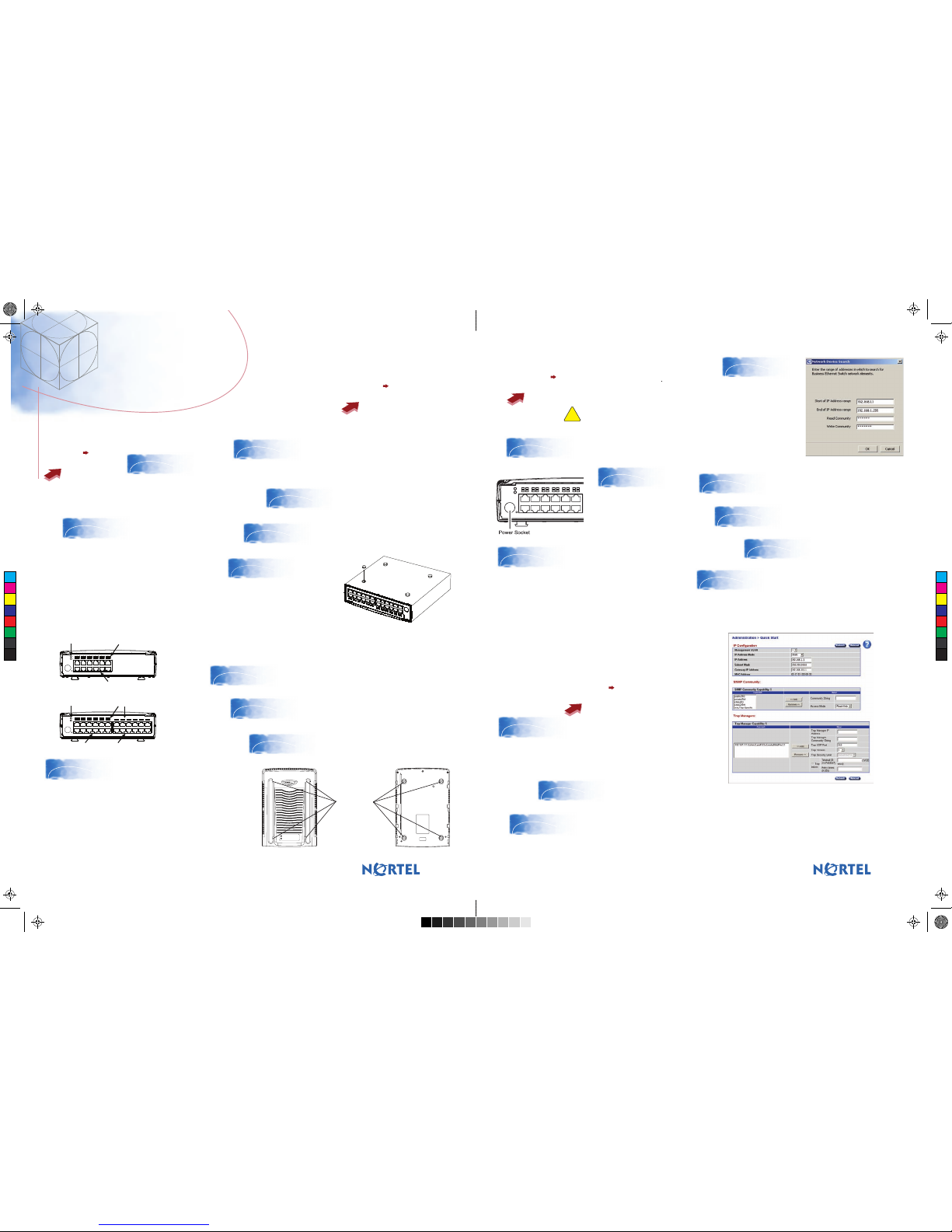
11. Insert the power adapter
into the DC power socket in the
front of the switch.
14. To access the BES50, first install the Business Element
Manager 1.0. Refer to Element Manager documentation at
www.nortel.com for instructions.
15. Start the Element Manager.
16. From the Element Manager
menu, choose Network > Find
Network Elements > Business
Ethernet Switch.
17. Enter the range
192.168.1.1 to
192.168.1.255 and then
click OK.
Note: By default the
Read Community is
“PlsChgMe!RO” and the
Write Community is
“PlsChgMe!RW”.
18. Select the BES device from the list of
network elements on the Element Manager
tree.
19. Click the Web Page button on the
Element Manager menu.
20. Enter the default username
(nnadmin) and password
(PlsChgMe!) to log on to the
BES50.
21. From the main menu, choose Administration > Quick Start. The
Quick Start screen appears showing the IP address and other items that
you can optionally configure. If you want to manually assign IP addresses,
refer to Using the Nortel Business Ethernet Switch 50 at www.nortel.com.
13. Check the front-panel LEDs as the device
powers on to confirm that the PWR LED is green.
If not, check that the power cable is correctly
plugged in.
Refer to Using the Nortel Business Ethernet Switch 50
at www.nortel.com for detailed installation
instructions.When you connect a PC directly to the
BES50, use the default IP address 192.168.1.128
You are now ready to use the BES50 series switch in
your network installation.
N0128198
BES50-FE/GE-24T PWR switch
BES50-FE/GE-12T PWR switch
RJ-45 Ports with PoE
The BES50 series switch performs a short self-test
as soon as you connect the switch to the power
supply. The status LED will flash green during the
self-test, then solid green when finished. If the
Status LED turns off, the device is not working
correctly. When the self-test finishes, the BES50
starts switching data.
7. If you mount the switch on a
desktop or flat surface, attach the
four adhesive feet to the device as
indicated.
RJ-45 Ports with PoE
System Indicators
Port/PoE Status Indicators
System Indicators
Port/PoE Status Indicators
RJ-45 Ports
Slots Feet
C
M
Y
CM
MY
CY
CMY
K
BES50_QuickInstallGuide4.pdf 9/13/2006 3:12:23 PM
 Loading...