

Nortel SRG50, BCM50, BCM50 3.0 Configuration Manual

SRG50 Configuration Guide
BCM50 3.0
Survivable Remote Gateway
Document Status: Standard
Document Number: NN40140-500
Document Version: 02.03
Date: June 2008

Copyright © 2006–2008 Nortel Networks, All Rights Reserved
All rights reserved.
The information in this document is subject to change without notice. The statements, configurations, technical data, and
recommendations in this document are believed to be accurate and reliable, but are presented without express or implied
warranty. Users must take full responsibility for their applications of any products specified in this document. The
information in this document is proprietary to Nortel Networks.
Trademarks
Nortel, the Nortel logo, and the Globemark are trademarks of Nortel Networks.
Microsoft, MS, MS-DOS, Windows, and Windows NT are trademarks of Microsoft Corporation.
All other trademarks and registered trademarks are the property of their respective owners.

Task List
Getting started . . . . . . . . . . . . . . . . . . . . . . . . . . . . . . . . . . . . . . . . . . . . . . . . .9
SRG50 overview . . . . . . . . . . . . . . . . . . . . . . . . . . . . . . . . . . . . . . . . . . . . . . .15
To activate the SRG keycode........................................................................................17
To reboot the system .....................................................................................................18
To verify that the SRG has been successfully created.................................................. 18
Task summary . . . . . . . . . . . . . . . . . . . . . . . . . . . . . . . . . . . . . . . . . . . . . . . .27
CS 1000 considerations . . . . . . . . . . . . . . . . . . . . . . . . . . . . . . . . . . . . . . . . .33
To configure SRG for NBWM and ADBWM ..................................................................40
To configure Alternative Call Routing with attendant service ........................................40
To configure Alternative Call Routing with DID trunks................................................... 41
To configure Emergency Services Access ....................................................................43
To configure on-site notification.....................................................................................43
To datafill the S1000 Main Office Settings panel...........................................................46
To enter the MOTN and BUID .......................................................................................49
To redirect the telephone to the main office call server .................................................49
3
IP telephones setup and configuration . . . . . . . . . . . . . . . . . . . . . . . . . . . .53
To set the IP telephone registration password ..............................................................53
To change local mode indication ...................................................................................55
To enter codec and jitter settings for IP telephones in local mode ................................55
To configure DN records for redirected IP telephones ..................................................56
To map received numbers to the DN.............................................................................59
To configure DHCP settings for SRG operation ............................................................60
To activate Test Local Mode .........................................................................................61
To exit Test Local Mode (and return to Normal Mode) ..................................................62
Setting up the private VoIP network . . . . . . . . . . . . . . . . . . . . . . . . . . . . . . .65
To enable MCDN TAT ................................................................................................... 69
To enter the QoS settings for VoIP trunks.....................................................................71
To enable fallback .........................................................................................................72
To configure gatekeeper settings for H323 trunks.........................................................73
To configure routing for outgoing calls ..........................................................................74
To configure remote access packages ..........................................................................76
To configure destination codes for the PSTN................................................................ 77
PSTN access and analog devices . . . . . . . . . . . . . . . . . . . . . . . . . . . . . . . .79
To configure the DNs for analog devices ......................................................................80
Troubleshooting . . . . . . . . . . . . . . . . . . . . . . . . . . . . . . . . . . . . . . . . . . . . . . .83
To manually redirect an IP telephone to the main office ...............................................86
Telephone features in normal and local mode . . . . . . . . . . . . . . . . . . . . . .89
Glossary . . . . . . . . . . . . . . . . . . . . . . . . . . . . . . . . . . . . . . . . . . . . . . . . . . . . .97
SRG50 Configuration Guide

4
NN40140-500NN40140-500

Contents
Getting started . . . . . . . . . . . . . . . . . . . . . . . . . . . . . . . . . . . . . . . . . . . . . . . . . 9
About this guide . . . . . . . . . . . . . . . . . . . . . . . . . . . . . . . . . . . . . . . . . . . . . . . . . . . . . . . 9
Audience . . . . . . . . . . . . . . . . . . . . . . . . . . . . . . . . . . . . . . . . . . . . . . . . . . . . . . . . . . . . 9
Acronyms . . . . . . . . . . . . . . . . . . . . . . . . . . . . . . . . . . . . . . . . . . . . . . . . . . . . . . . . . . . . 9
Symbols and conventions used in this guide . . . . . . . . . . . . . . . . . . . . . . . . . . . . . . . . 11
Related publications . . . . . . . . . . . . . . . . . . . . . . . . . . . . . . . . . . . . . . . . . . . . . . . . . . 12
How to get help . . . . . . . . . . . . . . . . . . . . . . . . . . . . . . . . . . . . . . . . . . . . . . . . . . . . . . 13
SRG50 overview . . . . . . . . . . . . . . . . . . . . . . . . . . . . . . . . . . . . . . . . . . . . . . . 15
SRG50 creation . . . . . . . . . . . . . . . . . . . . . . . . . . . . . . . . . . . . . . . . . . . . . . . . . . . . . . 16
SRG50 keycode activation . . . . . . . . . . . . . . . . . . . . . . . . . . . . . . . . . . . . . . . . . . . . . 17
SRG50 and BCM50 features comparison . . . . . . . . . . . . . . . . . . . . . . . . . . . . . . . . . . 18
Supported devices . . . . . . . . . . . . . . . . . . . . . . . . . . . . . . . . . . . . . . . . . . . . . . . . . . . . 19
SRG50 terminology . . . . . . . . . . . . . . . . . . . . . . . . . . . . . . . . . . . . . . . . . . . . . . . . . . . 20
Coordination with the main office call server . . . . . . . . . . . . . . . . . . . . . . . . . . . . . . . . 21
SRG operating modes . . . . . . . . . . . . . . . . . . . . . . . . . . . . . . . . . . . . . . . . . . . . . . . . . 21
Normal mode . . . . . . . . . . . . . . . . . . . . . . . . . . . . . . . . . . . . . . . . . . . . . . . . . . . . . 21
Local mode . . . . . . . . . . . . . . . . . . . . . . . . . . . . . . . . . . . . . . . . . . . . . . . . . . . . . . 23
SRG installation and configuration summary . . . . . . . . . . . . . . . . . . . . . . . . . . . . . . . 24
Process map for installing and configuring an SRG . . . . . . . . . . . . . . . . . . . . . . . . . . 26
Task summary . . . . . . . . . . . . . . . . . . . . . . . . . . . . . . . . . . . . . . . . . . . . . . . . 27
5
Foundation configuration . . . . . . . . . . . . . . . . . . . . . . . . . . . . . . . . . . . . . . . . . . . . . . . 27
IP telephone configuration . . . . . . . . . . . . . . . . . . . . . . . . . . . . . . . . . . . . . . . . . . . . . . 28
Dialing plan configuration . . . . . . . . . . . . . . . . . . . . . . . . . . . . . . . . . . . . . . . . . . . . . . 29
VoIP trunk configuration . . . . . . . . . . . . . . . . . . . . . . . . . . . . . . . . . . . . . . . . . . . . . . . 29
Call routing configuration . . . . . . . . . . . . . . . . . . . . . . . . . . . . . . . . . . . . . . . . . . . . . . . 31
Redirection and call forward configuration . . . . . . . . . . . . . . . . . . . . . . . . . . . . . . . . . 31
CS 1000 considerations. . . . . . . . . . . . . . . . . . . . . . . . . . . . . . . . . . . . . . . . . 33
CS 1000 and SRG terminology comparison . . . . . . . . . . . . . . . . . . . . . . . . . . . . . . . . 33
Normal and local mode overview . . . . . . . . . . . . . . . . . . . . . . . . . . . . . . . . . . . . . . . . 35
Normal mode . . . . . . . . . . . . . . . . . . . . . . . . . . . . . . . . . . . . . . . . . . . . . . . . . . . . . 35
Local mode . . . . . . . . . . . . . . . . . . . . . . . . . . . . . . . . . . . . . . . . . . . . . . . . . . . . . . 35
Survivability . . . . . . . . . . . . . . . . . . . . . . . . . . . . . . . . . . . . . . . . . . . . . . . . . . . . . . 36
Recovery to normal mode . . . . . . . . . . . . . . . . . . . . . . . . . . . . . . . . . . . . . . . . . . . 37
Testing the telephone in local mode . . . . . . . . . . . . . . . . . . . . . . . . . . . . . . . . . . . 37
Virtual trunk capacity . . . . . . . . . . . . . . . . . . . . . . . . . . . . . . . . . . . . . . . . . . . . . . . . . . 38
Vacant Number Routing (VNR) . . . . . . . . . . . . . . . . . . . . . . . . . . . . . . . . . . . . . . . . . . 38
Bandwidth management . . . . . . . . . . . . . . . . . . . . . . . . . . . . . . . . . . . . . . . . . . . . . . . 38
SRG50 Configuration Guide

6
Network Bandwidth Management (NBWM) . . . . . . . . . . . . . . . . . . . . . . . . . . . . . 39
Adaptive Network Bandwidth Management (ADBWM) . . . . . . . . . . . . . . . . . . . . . 39
Alternative Call Routing (ACR) . . . . . . . . . . . . . . . . . . . . . . . . . . . . . . . . . . . . . . . 39
Bandwidth management configuration: NBWM, ADBWM, and ACR . . . . . . . . . . . . . 40
Emergency Services Access (ESA) configuration . . . . . . . . . . . . . . . . . . . . . . . . . . . . 42
CS 1000 information for the SRG . . . . . . . . . . . . . . . . . . . . . . . . . . . . . . . . . . . . . . . . 44
S1000 Main Office Settings panel . . . . . . . . . . . . . . . . . . . . . . . . . . . . . . . . . . . . . 44
IP telephones redirection . . . . . . . . . . . . . . . . . . . . . . . . . . . . . . . . . . . . . . . . . . . . . . . 47
IP telephones numbers and models . . . . . . . . . . . . . . . . . . . . . . . . . . . . . . . . . . . 47
S1000 IP Terminal Details panel . . . . . . . . . . . . . . . . . . . . . . . . . . . . . . . . . . . . . . 48
IP telephone settings . . . . . . . . . . . . . . . . . . . . . . . . . . . . . . . . . . . . . . . . . . . . . . . 50
Firmware upgrade . . . . . . . . . . . . . . . . . . . . . . . . . . . . . . . . . . . . . . . . . . . . . . . . . . . . 51
Supported firmware . . . . . . . . . . . . . . . . . . . . . . . . . . . . . . . . . . . . . . . . . . . . . . . . 51
Firmware upgrade procedure . . . . . . . . . . . . . . . . . . . . . . . . . . . . . . . . . . . . . . . . 51
IP telephones setup and configuration . . . . . . . . . . . . . . . . . . . . . . . . . . . . 53
Registration password . . . . . . . . . . . . . . . . . . . . . . . . . . . . . . . . . . . . . . . . . . . . . . . . . 53
Local mode indication . . . . . . . . . . . . . . . . . . . . . . . . . . . . . . . . . . . . . . . . . . . . . . . . . 55
IP telephone codec and jitter settings . . . . . . . . . . . . . . . . . . . . . . . . . . . . . . . . . . . . . 55
Telephone (DN) records configuration . . . . . . . . . . . . . . . . . . . . . . . . . . . . . . . . . . . . 56
Received numbers configuration . . . . . . . . . . . . . . . . . . . . . . . . . . . . . . . . . . . . . . . . . 59
DHCP settings configuration . . . . . . . . . . . . . . . . . . . . . . . . . . . . . . . . . . . . . . . . . . . . 60
Call forwarding options . . . . . . . . . . . . . . . . . . . . . . . . . . . . . . . . . . . . . . . . . . . . . . . . 60
Configuration settings for redirected phones . . . . . . . . . . . . . . . . . . . . . . . . . . . . . . . . 61
Test Local Mode . . . . . . . . . . . . . . . . . . . . . . . . . . . . . . . . . . . . . . . . . . . . . . . . . . . . . 61
Features in local mode . . . . . . . . . . . . . . . . . . . . . . . . . . . . . . . . . . . . . . . . . . . . . . . . 62
911 Emergency Services Support . . . . . . . . . . . . . . . . . . . . . . . . . . . . . . . . . . . . . . . . 63
Setting up the private VoIP network. . . . . . . . . . . . . . . . . . . . . . . . . . . . . . . 65
Basic parameters . . . . . . . . . . . . . . . . . . . . . . . . . . . . . . . . . . . . . . . . . . . . . . . . . . . . . 67
Private dialing plan . . . . . . . . . . . . . . . . . . . . . . . . . . . . . . . . . . . . . . . . . . . . . . . . . . . 68
Meridian Customer Defined Network (MCDN) . . . . . . . . . . . . . . . . . . . . . . . . . . . . . . 69
QoS settings (codec, jitter buffer, and related items) . . . . . . . . . . . . . . . . . . . . . . . . . 70
Network security . . . . . . . . . . . . . . . . . . . . . . . . . . . . . . . . . . . . . . . . . . . . . . . . . . . . . 72
VoIP trunking configuration . . . . . . . . . . . . . . . . . . . . . . . . . . . . . . . . . . . . . . . . . . . . . 72
Fallback configuration . . . . . . . . . . . . . . . . . . . . . . . . . . . . . . . . . . . . . . . . . . . . . . 72
Gatekeeper routing . . . . . . . . . . . . . . . . . . . . . . . . . . . . . . . . . . . . . . . . . . . . . . . . 73
Line pools . . . . . . . . . . . . . . . . . . . . . . . . . . . . . . . . . . . . . . . . . . . . . . . . . . . . . . . . . . 74
Call routing . . . . . . . . . . . . . . . . . . . . . . . . . . . . . . . . . . . . . . . . . . . . . . . . . . . . . . . . . 74
Outgoing calls configuration . . . . . . . . . . . . . . . . . . . . . . . . . . . . . . . . . . . . . . . . . . . . 74
SRG PSTN access . . . . . . . . . . . . . . . . . . . . . . . . . . . . . . . . . . . . . . . . . . . . . . . . . . . 76
Remote Access Package for VoIP trunks . . . . . . . . . . . . . . . . . . . . . . . . . . . . . . . 76
PSTN destination codes configuration . . . . . . . . . . . . . . . . . . . . . . . . . . . . . . . . . 77
NN40140-500NN40140-500

Main office information . . . . . . . . . . . . . . . . . . . . . . . . . . . . . . . . . . . . . . . . . . . . . . . . 78
External attendant support . . . . . . . . . . . . . . . . . . . . . . . . . . . . . . . . . . . . . . . . . . . . . 78
PSTN access and analog devices . . . . . . . . . . . . . . . . . . . . . . . . . . . . . . . . 79
PSTN access considerations . . . . . . . . . . . . . . . . . . . . . . . . . . . . . . . . . . . . . . . . . . . . 79
Analog devices considerations . . . . . . . . . . . . . . . . . . . . . . . . . . . . . . . . . . . . . . . . . . 79
Troubleshooting. . . . . . . . . . . . . . . . . . . . . . . . . . . . . . . . . . . . . . . . . . . . . . . 83
IP telephone troubleshooting . . . . . . . . . . . . . . . . . . . . . . . . . . . . . . . . . . . . . . . . . . . . 83
IP terminal details . . . . . . . . . . . . . . . . . . . . . . . . . . . . . . . . . . . . . . . . . . . . . . . . . . . . 84
Probable causes for redirection failure . . . . . . . . . . . . . . . . . . . . . . . . . . . . . . . . . . . . 85
Troubleshooting fallback to local mode . . . . . . . . . . . . . . . . . . . . . . . . . . . . . . . . . . . . 86
IP telephones manual redirection . . . . . . . . . . . . . . . . . . . . . . . . . . . . . . . . . . . . . . . . 86
Cannot clear alarms using an alarm set . . . . . . . . . . . . . . . . . . . . . . . . . . . . . . . . . . . 87
Telephone features in normal and local mode . . . . . . . . . . . . . . . . . . . . . . 89
Normal mode . . . . . . . . . . . . . . . . . . . . . . . . . . . . . . . . . . . . . . . . . . . . . . . . . . . . . . . . 89
Local mode . . . . . . . . . . . . . . . . . . . . . . . . . . . . . . . . . . . . . . . . . . . . . . . . . . . . . . . . . 89
IP Phone 1110 in Local mode . . . . . . . . . . . . . . . . . . . . . . . . . . . . . . . . . . . . . . . . 90
IP Phone 1120E in Local mode . . . . . . . . . . . . . . . . . . . . . . . . . . . . . . . . . . . . . . . 91
IP Phone 1140E in Local mode . . . . . . . . . . . . . . . . . . . . . . . . . . . . . . . . . . . . . . . 91
IP Phone 2001 in Local mode . . . . . . . . . . . . . . . . . . . . . . . . . . . . . . . . . . . . . . . . 92
IP Phone 2002 in Local mode . . . . . . . . . . . . . . . . . . . . . . . . . . . . . . . . . . . . . . . . 92
IP Phone 2004 in Local mode . . . . . . . . . . . . . . . . . . . . . . . . . . . . . . . . . . . . . . . . 93
IP Phone 2007 in Local mode . . . . . . . . . . . . . . . . . . . . . . . . . . . . . . . . . . . . . . . . 93
IP Phone 2033 in Local mode . . . . . . . . . . . . . . . . . . . . . . . . . . . . . . . . . . . . . . . . 94
IP 2050 Softphone in Local Mode . . . . . . . . . . . . . . . . . . . . . . . . . . . . . . . . . . . . . 95
ATA extension features . . . . . . . . . . . . . . . . . . . . . . . . . . . . . . . . . . . . . . . . . . . . . . . . 95
Glossary . . . . . . . . . . . . . . . . . . . . . . . . . . . . . . . . . . . . . . . . . . . . . . . . . . . . . 97
7
SRG50 Configuration Guide

8
NN40140-500NN40140-500

Chapter 1
Getting started
About this guide
The SRG50 Configuration Guide describes how to install, configure, and maintain the Survivable
Remote Gateway (SRG) 50 Release 3.0.
The SRG50 is positioned as a cost-effective Small IP Branch Office solution for CS 1000 Main
office systems. The SRG50 offers business continuity and public switched telephone network
(PSTN) failover for voice over IP (VoIP) networks. An SRG provides transparent operation,
feature and application parity with a main office call server while in normal operating mode. If
connectivity with the call server or wide area network (WAN) is lost, the normal mode sets revert
back to local mode. The SRG takes ownership of call control for the local sets automatically and
provides internal communications as well as external connectivity to the PSTN.
SRG50 supports H323 and SIP Trunking and up to 80 survivable IP users with a single SRG
application authorization code. It is provided as a cost-effective VoIP business continuity solution
for small branch offices. The SRG50 supports CS 1000 Release 4.0, 4.5, 5.0, and 5.5.
9
Audience
The SRG50 Configuration Guide is intended for two audiences:
• the individuals responsible for engineering the SRG50 site and installing the BCM50,
configuring it for operation as an SRG50, and connecting it to the network
• the individuals responsible for post-installation system administration and
maintenance.
The SRG50 site engineer and installer must be familiar with BCM50 hardware and software, and
IP telephony and VoIP trunk configuration on the BCM50.
Acronyms
The following is a list of acronyms used in this guide.
Table 1 Acronyms used in this guide (Sheet 1 of 2)
Acronym Description
ACR Alternative call routing
ANBWM Adaptive network bandwidth management
ASM Analog station module
ATA Analog terminal adapter
SRG50 Configuration Guide

10 Chapter 1 Getting started
Table 1 Acronyms used in this guide (Sheet 2 of 2)
Acronym Description
BARS Basic alternate route selection
BUID Branch user ID
CDP Coordinated dialing plan
DDIM Digital drop and insert mux
DN Directory number
DSC Distant steering codes
DSM Digital station module
DTM Digital trunk module
ESA Emergency services access
ESDN Emergency services DN
FRL Facility restriction level
GATM Global analog trunk module
KEM Key expansion module
KRS Keycode retrieval system
LAN Local area network
LSC Local steering codes
MCDN Meridian customer defined network
MOTN Main office terminal number
MVC Mobile voice client
NARS Network alternate route selection
NBWM Network bandwidth management
NCS Network connection server
NRS Network routing service
PSTN Public switched telephone network
QoS Quality of service
SPN Special number
SRG Survivable remote gateway
TAT Trunk anti-tromboning
TRO Trunk route optimization
TSC Trunk steering codes
UDP Uniform dialing plan
VNR Vacant number routing
VoIP Voice over internet protocol
VPN Virtual private network
VPNI Virtual private network ID
WAN Wide area network
ZDP Zone digit prefix
NN40140-500NN40140-500
Symbols and conventions used in this guide
These symbols highlight critical information for the SRG system.
Caution: Alerts you to conditions where you can damage the equipment.
Danger: Alerts you to conditions where you can get an electrical shock.
Warning: Alerts you to conditions where you can cause the system to fail or
work improperly.
Note: Alerts you to important information.
Chapter 1 Getting started 11
Tip: Alerts you to additional information that can help you perform a task.
Security Note: Indicates a point of system security where you can change a
default or where the administrator must decide on the level of security required
!
for the system.
Warning: Alerts you to ground yourself with an antistatic grounding strap
before performing the maintenance procedure.
Warning: Alerts you to remove the main unit and expansion unit power cords
from the AC outlet before performing any maintenance procedure.
These conventions and symbols represent the Business Series Terminal display and dialpad.
Convention Example Used for
Word in a special font (shown in
the top line of the display)
Pswd:
Command line prompts on display telephones.
SRG50 Configuration Guide

12 Chapter 1 Getting started
Convention Example Used for
Underlined word in capital letters
(shown in the bottom line of a
two-line display telephone)
Dialpad buttons
PLAY
£
Display options on two-line display telephones.
Press the button directly below the option on the
display to proceed.
Buttons you press on the dialpad to select a
particular option.
These text conventions are used in this guide to indicate the information described.
Convention Description
bold Courier
text
Indicates command names, options, and text that you must enter.
Example: Use the
Example: Enter
info command.
show ip {alerts|routes}.
italic text Indicates book titles.
plain Courier
text
FEATURE
HOLD
Indicates command syntax and system output (for example, prompts
and system messages).
Example:
Set Trap Monitor Filters
Indicates that you press the button with the corresponding icon on the
set you are using.
RELEASE
Related publications
This section provides a list of additional documents referred to in this guide.
Administration Guide (NN40020-600)
Device Configuration Guide (NN40020-300)
Installation Checklist and Quick Start Guide (NN40020-308)
Installation and Maintenance Guide (NN40020-302)
Main Office Configuration Guide for SRG50 (NN43001-307)
Networking Configuration Guide (NN40020-603)
Telephony Device Installation Guide (NN40020-309)
NN40140-500NN40140-500

How to get help
This section explains how to get help for Nortel products and services.
Getting Help from the Nortel Web site
The best way to get technical support for Nortel products is from the Nortel Technical Support
Web site:
http://www.nortel.com/support
This site provides quick access to software, documentation, bulletins, and tools to address issues
with Nortel products. More specifically, the site enables you to:
• download software, documentation, and product bulletins
• search the Technical Support Web site and the Nortel Knowledge Base for answers to
technical issues
• sign up for automatic notification of new software and documentation for Nortel
equipment
• open and manage technical support cases
Chapter 1 Getting started 13
Getting Help over the phone from a Nortel Solutions Center
If you don’t find the information you require on the Nortel Technical Support Web site, and have a
Nortel support contract, you can also get help over the phone from a Nortel Solutions Center.
In North America, call 1-800-4NORTEL (1-800-466-7835).
Outside North America, go to the following Web site to obtain the phone number for your region:
http://www.nortel.com/callus
Getting Help from a specialist by using an Express Routing Code
To access some Nortel Technical Solutions Centers, you can use an Express Routing Code (ERC)
to quickly route your call to a specialist in your Nortel product or service. To locate the ERC for
your product or service, go to:
http://www.nortel.com/erc
Getting Help through a Nortel distributor or reseller
If you purchased a service contract for your Nortel product from a distributor or authorized
reseller, contact the technical support staff for that distributor or reseller.
SRG50 Configuration Guide

14 Chapter 1 Getting started
NN40140-500NN40140-500

Chapter 2
SRG50 overview
The SRG50 is a software application that leverages the BCM50 platform. It is optimized to
provide feature transparency to the main office call server and to act as a survival remote gateway
in a CS 1000 IP branch office environment.
SRG50 supports up to 80 survivable IP users with a single SRG application authorization code.
SRG50 Release 3.0 operates with CS 1000 running Release 4.0, 4.5, 5.0, and 5.5.
Configure SRG50 with Business Element Manager (Element Manager) or Network Configuration
Manager (NCM). For detailed information about managing SRG50 with NCM, see your NCM
documentation.
For a summary of differences between SRG versions, see the following table.
Table 2 Summary of supported features on the different SRG versions (Sheet 1 of 2)
15
Features SRG 1.5 on BCM 200/
Platform Available on BCM 200/
Call Servers CS1000 Release 3.0,
Trunking H323 is supported. H323 is supported. When CS1000 is
IP clients IP Phones 2001, 2002
Number of IP
clients
supported
NetIQ Not supported Not supported Supported Supported
PVQM Not supported Not applicable Supported Supported
400
400 hardware.
SRG 1.5 is not
available on BCM1000
hardware.
4.0, and 4.5
(phase 1 and 2), 2004
(phase 1 and 2), 2007.
IP KEM, IP Phone
2050 series.
IP Phone 1110, 1120,
1140, IP Phone 2033
(polycom), WLAN
2210/2211/2212.
90 32 80 80
SRG50 1.0 SRG50 2.0 SRG50 3.0
Available on standard
BCM50 hardware.
SRG50 1.0 is not
available on BCM50a
or BCM50e hardware.
CS1000 Release 3.0,
4.0, and 4.5
IP Phones 2001, 2002
(phase 1 and 2), 2004
(phase 1 and 2), 2007.
IP KEM, IP Phone
2050 (v1).
IP Phone 2033
(polycom), 2122
Available on standard
BCM50 and BCM50b
hardware only.
SRG50 2.0 is not
available on BCM50a,
BCM50ba, BCM50e,
and BCM50be
hardware.
CS1000 Release 4.0,
4.5, and 5.0
supported by SRG,
both H323 and SIP
trunks are supported
between them.
IP Phones 2001, 2002
(phase 1 and 2), 2004
(phase 1 and 2), 2007.
IP KEM, IP Phone
2050 series.
IP Phone 1120, 1140,
IP Phone 2033
(polycom), WLAN
2210/2211/2212.
Available on standard
BCM50 and BCM50b
hardware only.
SRG50 3.0 is not
available on BCM50a,
BCM50ba, BCM50e,
and BCM50be
hardware.
CS1000 Release
4.0,4.5, and 5.0
H323 and SIP trunking
are supported.
IP Phones 2001, 2002
(phase 1 and 2), 2004
(phase 1 and 2), 2007.
IP KEM, IP Phone
2050 series.
IP Phone 1110, 1120,
1140, IP Phone 2033
(polycom), WLAN
2210/2211/2212.
SRG50 Configuration Guide

16 Chapter 2 SRG50 overview
Table 2 Summary of supported features on the different SRG versions (Sheet 2 of 2)
Features SRG 1.5 on BCM 200/
ESA Supported Supported Supported Supported.
Vo911 Supported Supported Supported Supported.
Enhanced
firmware
download
Analog station
support
400
Supported Supported Supported Supported
The number supported
depends on the
hardware.
For BCM200: two
analog station modules
are supported.
number of analog
nodes= 2*8 =16.
For BCM400: Four
analog station modules
are supported.
number of analog
nodes= 4*8 =32)
SRG50 1.0 SRG50 2.0 SRG50 3.0
On Site Notification
(OSN) of E911 alarms
supported for local
users through a third
party tool.
Two analog station
modules are
supported.
number of analog
nodes= 2*8 =16)
Two analog station
modules are
supported.
number of analog
nodes= 2*8 =16)
Two analog station
modules are
supported.
number of analog
nodes= 2*8 =16)
SRG50 creation
An SRG50 is created by applying the appropriate SRG keycode to a functional BCM50 system.
SRG50 is only supported on the BCM50 and BCM50b main units. Integrated router versions of
the BCM50 (BCM50a, BCM50e, BCM50ba, and BCM50be) do not support the SRG50
application.
The Installation Checklist and Quick Start Guide is provided on the SRG50 Documentation CD
that is shipped with your SRG50 system. Instructions in that guide are referenced in the following
procedures. Also, the relevant BCM50 default IP addresses, user names, and passwords are
excerpted from that guide and provided for your reference in the table BCM50 default IP addresses
on page 16 and the table BCM50 default user names and passwords on page 17.
Table 3 BCM50 default IP addresses
Port IP address Subnet mask
OAM port (see Note) 10.10.11.1 255.255.255.252
BCM50 LAN (no router) 192.168.1.2 255.255.255.0
Note: DHCP is enabled on the OAM port and assigns the following IP address: 10.10.11.2
NN40140-500NN40140-500

Table 4 BCM50 default user names and passwords
Tool User ID| User Name Password
Element Manager nnadmin PlsChgMe!
Onbox main web page
(http:// [IP address]
nnadmin PlsChgMe!
SRG50 keycode activation
To create an SRG50, use Element Manager to activate the SRG keycode on a BCM50 system
(BCM50 or BCM50b main unit).
To activate the SRG keycode
1 Locate the SRG authorization codes supplied with your product.
2 Open Element Manager. For information about installing and opening Element Manager, see
the Installation Checklist and Quick Start Guide (NN40020-308).
3 With Element Manager, connect to the BCM system that you want to convert to an SRG. For
information about connecting to a BCM system, see the Installation Checklist and Quick Start
Guide (NN40020-308).
Chapter 2 SRG50 overview 17
4 Navigate to the Keycodes panel (Configuration > System > Keycodes).
5 Click Connect to Nortel Keycode Retrieval system to obtain the keycode file for your
system from the Nortel Keycode Retrieval System (KRS).
For more information about keycodes, see the Keycode Installation Guide (NN40010-301).
6 In the KRS, generate the keycode file for your system and save it on your management
computer.
Make sure the SRG feature is included in your keycode as well as any other features you
require for your system. To use the on-site notification for Emergency Services, you need to
include a LAN CTE port in your keycode.
7 In Element Manager, return to the keycodes panel.
8 Click Load File.
9 Browse to the location on your management computer containing the keycode file for this
system.
10 Select the keycode file, and then click Open.
The keycode file is applied.
11 Reboot your system to complete the creation of the SRG.
SRG50 Configuration Guide

18 Chapter 2 SRG50 overview
To reboot the system
1 In Element Manager, navigate to the Reset panel (Administration > Utilities > Reset).
2 Click Reboot BCM50 System.
To verify that the SRG has been successfully created
1 In Element Manager, navigate to the Keycodes panel (Configuration > System > Keycodes).
In the Feature licenses table, verify that the status of the SRG keycode is ACTIVE.
2 Open the Resources folder (Configuration > Resources).
Verify that there is a Survivable Remote Gateway panel.
SRG50 and BCM50 features comparison
The table Comparison of BCM50 and SRG50 on page 18 compares SRG50 and BCM50 features.
Table 5 Comparison of BCM50 and SRG50 (Sheet 1 of 2)
Item BCM50 SRG50
MBMs See the
Installation and
Maintenance
Guide
(NN40020-302)
Digital telephone sets Yes No
FCAPS Yes Yes, extended to include SRG-specific
Network Configuration Manager Yes Yes
Telset Administration Yes No
CS 1000 Geographic Redundancy N/A Yes
CS 1000 Network Bandwidth Management N/A Yes
Recommended:
ASM8+ (8 port Analog Station Module); DTM
(Digital Trunk Module - 24 lines on either T1
or E1 or PRI); BRI (4 line BRI S/T Module);
GATM4 (Global Analog Trunk MBM - 4 port);
GATM8 (Global Analog Trunk MBM - 8 port)
ADID4 (4 analog lines)
ADID8 (8 analog lines)
G4x16 (16 digital ports and 4 analog trunks);
G8x16 (16 digital ports and 8 analog trunks)
Supported for ATA connections:
DSM16 (Digital Station Module - 16 ports);
DSM32 (Digital Station Module - 32 ports);
4x16 Combo (16 digital ports, 4 analog
trunks and 1 analog station);
Does not support:
DDIM (Digital Drop and Insert Mux)
FEM (Fiber Expansion Module)
DECT (Digital Enhanced Cordless
Telecommunications)
alarms and keycodes
NN40140-500NN40140-500

Chapter 2 SRG50 overview 19
Table 5 Comparison of BCM50 and SRG50 (Sheet 2 of 2)
Item BCM50 SRG50
CS 1000 Adaptive Network Bandwidth Management N/A Yes
CS 1000 Alternative Call Routing N/A Yes
CS 1000 Emergency Services Access N/A Yes
Firmware Download from main office call server N/A Yes (CS 1000 Release 4.0, 4.5, 5.0, and 5.5)
(CS 1000 Release 4.0 requires patch
MPLR22418)
SRG-specific features for interaction with a main
office call server, including: Heartbeat detection of
WAN recovery; IP telephone redirection to main
office in Normal Mode; Local Mode IP telephone
interface; H.323 Gateway to PSTN under control of
main office call server
N/A Yes
Supported devices
The SRG50 Release 3.0 supports:
• IP Phones 1110, 1120E, and 1140E
• IP Phone 2001, 2002, 2004, 2007, and 2033
• IP Phone Key Expansion Module (KEM) – The IP Phone KEM is supported on an
SRG with normal mode IP Phones. It does not function with local mode or test local
mode IP Phones.
• IP Softphone 2050 v1/v2 and Mobile Voice Client (MVC) 2050
• WLAN Handsets 2210, 2211, and 2212
• WLAN Handsets 6120 and 6140
• WLAN Handsets 1210, 1220, and 1230
• Analog (500/2500 type) telephones
• Analog devices such as fax machines
Note: Throughout this document, the IP Phones in this list are referred to collectively as
IP Phones.
The SRG50 is positioned primarily to support IP telephones and clients. However, analog devices
can be supported using analog station modules (ASM), or by using an analog terminal adapter
(ATA2) in conjunction with a digital station module (DSM). The SRG50 does not support digital
or ISDN telephones.
SRG50 Configuration Guide

20 Chapter 2 SRG50 overview
SRG50 terminology
The table SRG50 terminology on page 20 identifies SRG terms that may be unfamiliar to main
office installers. They are provided to facilitate communications between SRG and main office
personnel. In the table, the Element Manager path where the term appears is provided for reference
and may not represent every appearance of the term.
Table 6 SRG50 terminology (Sheet 1 of 2)
Term Description
Port For telephony configuration (Configuration > Telephony), a port is an internal number that
identifies a physical termination point for a telephone set or a physical trunk.
For the configuration of resources (Configuration > Resources) and data services
(Configuration > Data Services), port is used in the context of the TCP/IP protocol suite.
IP Terminal IP telephone
Configuration > Resources > Telephony Resources > IP & App Sets
Sets Can refer to actual telephones, or to the directory number (DN) assigned to the port to
which a particular telephone is connected.
Telephone
Configuration > Resources > Telephony Resources > IP & App Sets
Mapping DN to Telephone
Configuration > Telephony > Sets
DN
Configuration > Telephony > Lines > Target Lines > Target Lines table > Control Set and
Prime Set columns
Trunks Trunks refer to external facilities that are connected to the SRG and provide incoming and
Loop trunk An analog loop (FXO) that connects to the PSTN: a POTS line.
Lines A line is the generic term used for all communication paths, both internal and external.
Physical Lines Physical trunks.
VoIP Lines VoIP trunks.
outgoing communication paths. Paths can be physical (examples: loop; PRI; T1) or virtual
(VoIP trunks).
Configuration > Resources
Configuration > Telephony > Lines
Configuration > Telephony > Lines > Active Physical Lines
(Lines 061 to 124)
Configuration > Telephony > Lines > Active VoIP Lines
(Lines 001 to 024)
NN40140-500NN40140-500

Chapter 2 SRG50 overview 21
Table 6 SRG50 terminology (Sheet 2 of 2)
Term Description
Target Lines Target lines are internal, virtual paths between trunks and telephones for incoming calls
(only). They provide flexibility in the way trunks and telephones can be associated: target
lines can be used to direct an incoming call to one or more telephones, direct one or
more trunks to one phone, or direct several trunks (in a line pool) to one or more phones.
Target lines are assigned to DNs. A target line triggers ringing voltage to the telephone(s)
connected to the port(s) associated with the DN(s) that the target line is assigned to. (For
example, if a unique target line is assigned to each DN, only one telephone rings when
the DN is called. If several DNs are assigned to one target line, calling any of the DNs
ring all of the associated phones.)
Target lines are required for auto-answer trunks. Because VoIP lines are set internally to
auto-answer, target lines are required for SRG operation.
Element Manager provides two methods for assigning target lines to DNs.
1) Configuration > Telephony > Sets > All DNs > All DNs table > Details for DN subpanel
> Line Assignment tab
or
2) Configuration > Telephony > Lines > Target Lines > Target Lines table > Details for
Line subpanel > Assigned DNs tab
The first method provides a convenient way to assign the target line to the DN when the
DN record is configured. The second method provides fields that allow incoming digit
strings to be mapped to the DN.
(Lines 125 to 268)
For more information about target lines, see the Networking Configuration Guide
(NN40020-603).
Line pool Several of the same type of trunk configured as one group: a trunk group.
Coordination with the main office call server
Configuration of the SRG branch office requires datafill at both the SRG and the main office call
server. Main office configuration drives SRG configuration, and Nortel recommends that the main
office activities be concluded before undertaking SRG configuration.
For information, see CS 1000 considerations on page 33.
SRG operating modes
The SRG has two operating modes:
• Normal mode
• Local mode
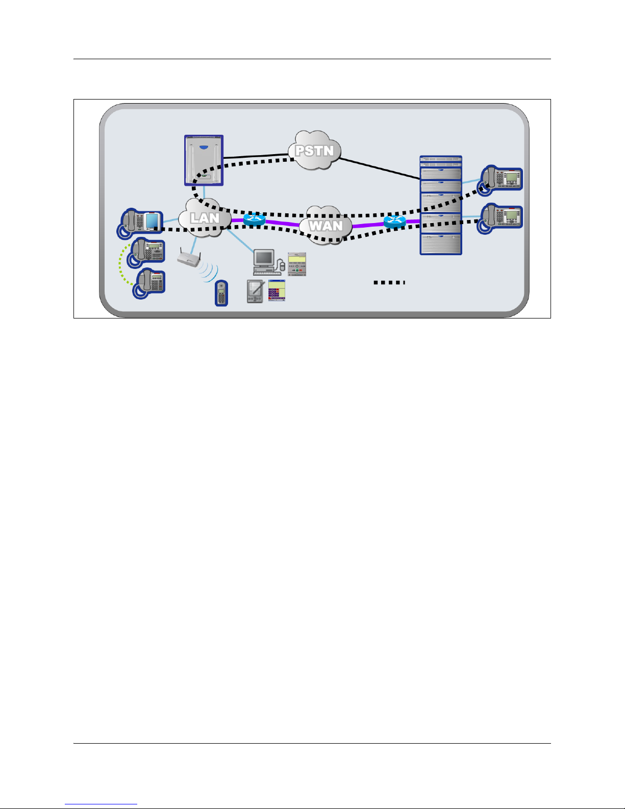
Normal mode
In normal mode (see the figure Normal mode on page 22), the SRG is connected to the main office
call server over a WAN using VoIP trunks. From the perspective of the main office, the SRG is a
branch office.
SRG50 Configuration Guide
22 Chapter 2 SRG50 overview
Figure 1 Normal mode
Branch office
IP phones
WLAN
handsets
SRG
Software
phones
VoIP connection over WAN
Main office
IP phones
Normal mode
IP telephones connected at the SRG are registered with the main office call server and are under
main office control. They operate as branch user sets and have access to all telephony services and
features that the call server offers to IP telephones connected directly to the main office.
When a branch user set initiates a local PSTN call, the main office sets up the call using the VoIP
trunks, which establishes a local media path. Emergency Services Access calls are similarly routed
to the SRG PSTN. The telephone is redirected to local mode and the SRG initiates a local PSTN
call to 911. For main office callers, the SRG acts as a VoIP-PSTN gateway during normal mode.
When call forwarding has been configured, incoming PSTN calls to the branch user set are
forwarded over VoIP trunks (either H.323 or SIP) to the main office, which terminates the call at
the branch user. Similarly, calls from analog telephones connected to the SRG to the branch user
set are forwarded to the main office over VoIP trunks, which then terminates the call at the branch
user. Calls from the branch user set to the analog telephones at the SRG are routed over the VoIP
trunks to terminate at the analog telephone. In all these call scenarios, only signaling messages go
through the VoIP trunk. The media path is set up directly between the branch user set and the voice
gateway at the SRG. This means that these calls do not use any WAN bandwidth between the main
office and the branch office after calls are established.
When a branch user IP telephone calls a main office IP telephone and vice versa, the call is a
simple station-to-station call within the main office call server. Since the branch user IP telephone
is physically remote from the call server, the media path goes through the WAN connection
between the main office and the SRG, and thus uses WAN bandwidth, as demanded by the codec
used in the call.
NN40140-500NN40140-500
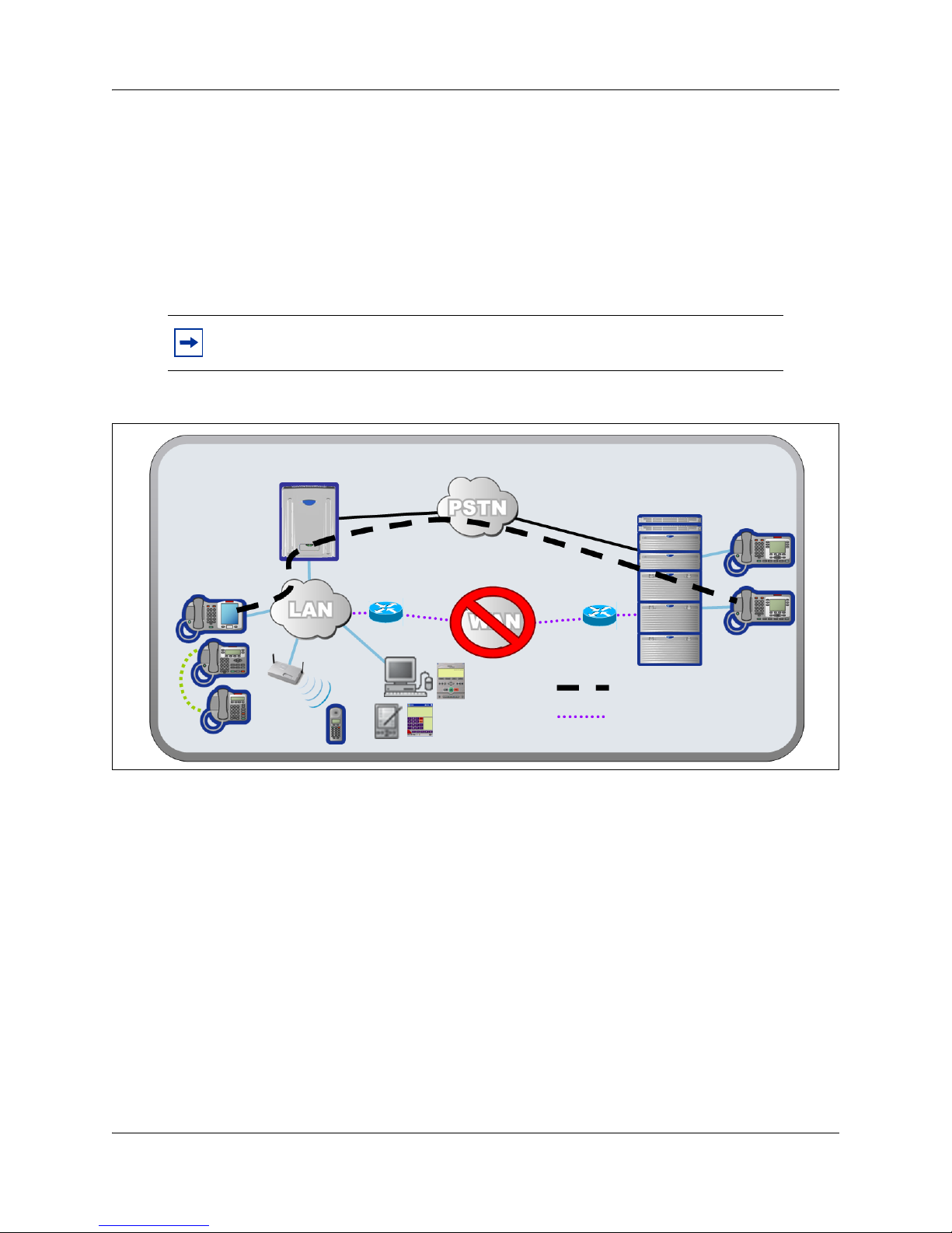
Local mode
In the event of a WAN failure or the call server at the main office becomes unavailable, the
IP Phones in normal mode revert to local mode automatically. In local mode, the IP users
connected to the SRG are under the control of the SRG. When in local mode, main office call
features are not available to users attached to the SRG. The SRG offers a set of basic features for
the IP telephones, including access to the local PSTN, dialing emergency service numbers, and
calling local extensions. For a complete list of local mode features, see Features in local mode on
page 62. Local mode is illustrated in the figure Local mode on page 23.
Note: The IP Phone KEM is supported on an SRG with normal mode IP Phones.
It does not function with local mode or test local mode IP Phones.
Figure 2 Local mode
Chapter 2 SRG50 overview 23
Branch office
IP phones
WLAN
handsets
SRG
Software
phones
WAN connectivity lost,
PSTN provides fallback
SRG
Main office
IP phones
polling
Local mode
The SRG handles all call processing. Calls between two IP telephones at the SRG are handled
locally as a simple station-to-station call. When an IP telephone initiates a local PSTN call, the
SRG routes the call to a trunk that is connected to the local PSTN. Incoming DID calls are also
handled by the SRG and terminated on the appropriate IP telephone set.
In local mode, the IP telephones do not have access to the main office network over the VoIP
trunks. If alternate routes are configured, then calls can be made to the main office or other branch
offices using the available PSTN trunks.
Several situations, described below, can cause the IP phone to be in local mode.
Initial registration
When the IP telephone is installed, it first registers with the SRG, and is in local mode. When the
SRG configuration at the main office and the SRG is complete the IP telephone is redirected to the
main office, where it registers as a branch user and changes from local mode to normal mode.
SRG50 Configuration Guide

24 Chapter 2 SRG50 overview
Automatic registration with the main office
When configured as a branch office user set, an IP telephone at the SRG automatically attempts to
register with the main office when:
• The phone is in local mode because of loss of connectivity with the main office, and
the SRG is redirecting it back to the main office because connectivity has been
reestablished (see Loss of WAN or VoIP connectivity on page 24).
• The phone is in local mode because Test Local Mode was invoked and the timer has
expired or the Exit button is pressed.
• The phone is in local mode, the main office is a CS 1000, and this is the first time that
the phone has been redirected to the main office.
The IP telephone can fail to register with the main office for several reasons. These are detailed in
Probable causes for redirection failure on page 85.
Loss of WAN or VoIP connectivity
The WAN or VoIP connectivity between the main office and the SRG can become unavailable if,
for example, router failure occurs, the main office becomes unavailable, a WAN failure occurs, or
the VoIP trunks reach capacity. When VoIP connectivity is lost, each IP telephone loses its
connection with the main office terminal proxy server. The IP telephones reboot and reregister at
the SRG, placing them in local mode. If enabled, call forwarding to the main office is
automatically cancelled.
The IP telephones remain under the control of the SRG until VoIP connectivity is confirmed.
When confirmation is received, the IP telephones are automatically redirected to the main office;
redirection requires no user intervention. If the telephone is busy at the time that connectivity is
reestablished, the SRG redirects the phone when it is free.
Test Local Mode
Test Local Mode is a facility that allows the IP telephone to be redirected back to the SRG when it
is in normal mode. This forces the IP telephone to go into local mode and allows the telephone
user or system administrator to test local mode operation without taking down the VoIP trunks to
the main office. Implementation of Test Local Mode depends on the main office call server. For
more information, see CS 1000 considerations on page 33.
SRG installation and configuration summary
The SRG50 Configuration Guide provides information specific to configuring a BCM50 as an
SRG. Information pertaining to generic BCM50 practices and procedures is provided in the
BCM50 documentation suite.
Generally, SRG50 activities leverage an installer’s general knowledge of BCM50 activities.
However, Nortel recommends that the BCM50/SRG50 site engineer and installer familiarize
themselves with SRG-specific requirements before starting any installation activities.
NN40140-500NN40140-500

Chapter 2 SRG50 overview 25
The figure Process map for installing and configuring an SRG on page 26 provides a process map
for installing and configuring an SRG50. The procedures in this document assume that the
following activities have been completed:
• The BCM50, including media bay modules, cabling, telephones, and peripherals, have
been installed.
• BCM50 administration has been set up.
• The basic parameters of the BCM50 have been configured.
• CS1000 main office system has been installed and configured to support SRG.
• The SRG has been connected to the LAN (as required) and WAN (to the main office).
• System functionality has been tested to this point.
• Attached devices have been installed and configured (for information about
configuring IP Phones, see IP telephones setup and configuration on page 53).
• Non-SRG-specific networking and device configuration has been completed (for
information about configuring the network, see Setting up the private VoIP network on
page 65).
SRG50 Configuration Guide
26 Chapter 2 SRG50 overview
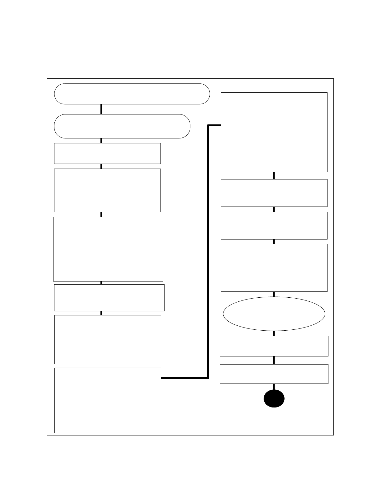
Process map for installing and configuring an SRG
Figure 3 Process map for installing and configuring an SRG
The main office is installed and running and the
information to support SRG has been configured.
You have reviewed the SRG and BCM50
system requirements and documentation.
Locate the BCM50 that will be
converted to the SRG.
Install the physical components,
including media bay modules,
cabling, telephones, and
peripherals, as per the Installation
and Maintenance Guide.
Install and configure attached
devices. See IP telephones setup
and configuration on page 53 when
configuring the IP telephones. See
PSTN access and analog devices on
page 79 when setting up analog
trunks and devices.
Set up the IP telephones for SRG
operation, as per IP telephones
setup and configuration on page 53.
Configure the basic parameters of the
BCM50 as per the Installation
Checklist and Quick Start Guide. (see
the Installation and Maintenance
Guide (NN40020-302) and the
Administration Guide (NN40020-600)).
Create the SRG (see SRG50 creation
on page 16).
Complete the initial installation,
connect the SRG to the LAN (as
required) and WAN (to main office),
and test the SRG system, as per the
Installation and Maintenance Guide
(NN40020-302).
Set up SRG administration, and
carry out non-SRG-specific
networking and device configuration
as per the Administration Guide
(NN40020-600), the Networking
Configuration Guide (NN40020-603),
and the Device Configuration
Guide (NN40020-300).
Set up the private VoIP network, as
per Setting up the private VoIP
network on page 65.
Configure the server-specific data for
the main office call server (see the
documentation for your call server).
Register each telephone
with the main office and the
SRG.
Troubleshoot any registration issues
(Troubleshooting on page 83).
Test the telephones and analog
equipment in normal mode.
Familiarize users with the services for
local mode. (Telephone features in
normal and local mode on page 89)
NN40140-500NN40140-500

Chapter 3
Task summary
The task summary offers a high level, chronological review of the tasks required to configure the
SRG50. The paths (Xxxx > Yyyy > Zzzz) direct you to the appropriate Business Element Manager
(Element Manager) panels.
Foundation configuration
Foundation configuration refers to configuration that is done as part of BCM50 foundation
activities. The items identified here are significant for SRG operation and main office planning
and installation.
1 Configure the SRG IP address, net mask, and gateway.
Configuration >System > IP Subsystem
External Reference: Installation and Maintenance Guide (NN40020-302)
27
2 Confirm the number of IP sets and VoIP trunks.
Configuration > Resources > Application Resources
The Licence column indicates the number of resources available.
External Reference: Keycode Installation Guide (NN40010-301)
3 Verify the global telephony settings.
Configuration > Telephony > Global Settings
External Reference: Device Configuration Guide (NN40020-300)
4 Configure the Start DN (determined by the dialing plan).
Administration > Utilities > Reset > Cold Reset Telephony Services button > Cold Reset
Telephony dialog box > Start DN field
Internal Reference: Basic parameters on page 67
External Reference: Installation and Maintenance Guide (NN40020-302)
5 Verify the DN length.
i) For local calls between telephones on the SRG.
Configuration > Telephony > Dialing Plan > General > Dialing Plan - General panel >
Global Settings subpanel > DN length (intercom) field
ii) For incoming calls from the PSTN
Configuration > Telephony > Dialing Plan > Public Network > Dialing Plan - Public
Network panel> Public Network Settings subpanel > Public Received number length
field
SRG50 Configuration Guide

28 Chapter 3 Task summary
iii) For calls coming in from the private network
Configuration > Telephony > Dialing Plan > Private Network > Dialing Plan - Private
Network panel > Private Network Settings subpanel > Private Received number length
field
and
Configuration > Telephony > Dialing Plan > Private Network > Dialing Plan - Private
Network panel > Private Network Settings subpanel > Private DN length field
(Private DN length is used for DPNSS applications only. See the Networking Configuration
Guide (NN40020-603).)
Internal Reference: Basic parameters on page 67
External Reference: Networking Configuration Guide (NN40020-603)
6 Verify the line pool assignment of VoIP trunks.
In the default configuration, the VoIP trunks are assigned to line pool BlocA. Instructions in
the SRG50 Configuration Guide assume that the default configuration has been maintained.
Configuration > Telephony > Lines > Active VoIP Lines > Active VoIP Lines table > Line
Type column > Line Type field
External Reference: Networking Configuration Guide (NN40020-603)
7 The SRG supports four analog loop trunks on the main unit*. Verify the line pool assignment
of these trunks.
In the default configuration, these trunks are assigned to line pool A. Instructions in the
SRG50 Configuration Guide assume that the default configuration has been maintained.
Configuration > Telephony > Lines > Active Physical Lines > Active Physical Lines table
> Line Type column > Line Type field
External Reference: Networking Configuration Guide (NN40020-603)
* Category 1 countries
IP telephone configuration
1 Configure the registration password.
Configuration > Resources > Telephony Resources > IP Sets row > Details for Module
subpanel > IP Terminal Global Settings tab
Internal Reference: Registration password on page 53
2 Configure the local mode indication (Advertisement/Logo).
Configuration > Resources > Telephony Resources > IP Sets row > Details for Module
subpanel > IP Terminal Global Settings tab
Internal Reference: Local mode indication on page 55
NN40140-500NN40140-500

Chapter 3 Task summary 29
3 Configure the IP telephone codec and jitter settings.
Configuration > Resources > Telephony Resources > IP Sets row > Details for Module
subpanel > IP Terminal Global Settings tab
Internal Reference: IP telephone codec and jitter settings on page 55
4 Configure the telephone (DN) records.
Configuration > Telephony > Sets > All DNs
Internal References: Telephone (DN) records configuration on page 56
5 Configure the received numbers.
Configuration > Telephony > Lines > Target Lines
Internal Reference: Received numbers configuration on page 59
External Reference: Networking Configuration Guide (NN40020-603)
6 Decide on the call forwarding option.
Internal Reference: Call forwarding options on page 60
7 Configure the IP telephones.
Internal Reference: Configuration settings for redirected phones on page 61
Dialing plan configuration
1 Configure the private network type (CDP or UDP).
Configuration > Telephony > Dialing Plan > Private Network > Dialing Plan - Private
Network panel > Private Network Settings subpanel > Private network type
Internal Reference: Private dialing plan on page 68
External Reference: Networking Configuration Guide (NN40020-603)
2 Enable MCDN TAT.
Configuration > Telephony > Dialing Plan > Private Network > Dialing Plan - Private
Network panel > MCDN subpanel
Internal Reference: Meridian Customer Defined Network (MCDN) on page 69
External Reference: Networking Configuration Guide (NN40020-603)
VoIP trunk configuration
Your SRG VoIP trunks are either H323 trunks, SIP trunks, or a combination of both types.
1 Configure routing table.
Configuration > Resources > Telephony Resources > Modules panel > IP Trunks row >
Routing Table.
External Reference: Networking Configuration Guide (NN40020-603)
SRG50 Configuration Guide

30 Chapter 3 Task summary
2 Configure VoIP trunk QoS settings.
Configuration > Resources > Telephony Resources > Modules panel > IP Trunks row >
H323 Media Parameters tab or SIP Media Parameters tab
Internal Reference: QoS settings (codec, jitter buffer, and related items) on page 70
External Reference: Networking Configuration Guide (NN40020-603)
3 Enable or disable fallback.
Configuration > Resources > Telephony Resources > Modules panel > IP Trunks row >
H323 Settings tab or SIP Settings tab
Internal References:
Fallback configuration on page 72
SRG PSTN access on page 76
External Reference: Networking Configuration Guide (NN40020-603)
4 Configure H323 settings.
Configuration > Resources > Telephony Resources > Modules panel > IP Trunks row >
H323 Settings tab
Internal Reference: Gatekeeper routing on page 73
External Reference: Networking Configuration Guide (NN40020-603)
5 Configure SIP settings.
Configuration > Resources > Telephony Resources > Modules panel > IP Trunks row >
SIP Settings tab
External Reference: Networking Configuration Guide (NN40020-603)
6 Assign VoIP trunks to a line pool (if default configuration has not been maintained).
Configuration > Telephony > Lines > Active VoIP Lines
Internal Reference:Line pools on page 74
External Reference: Networking Configuration Guide (NN40020-603)
Note: In configuring SIP trunks, the SRG BCM shall register itself with the configured H323ID with NRS
in CS1000. It is with this ID, the SRG will get MOTPS IP address from NCS.
7 Assign PSTN trunks to a line pool (if default configuration has not been maintained).
Configuration > Telephony > Lines > Active Physical Lines
Internal Reference:Line pools on page 74
External Reference: Networking Configuration Guide (NN40020-603)
8 Assign remote access packages to the VoIP trunks.
Configuration > Telephony > Call Security > Remote Access Packages
Internal Reference: SRG PSTN access on page 76
External Reference: Networking Configuration Guide (NN40020-603)
NN40140-500NN40140-500
 Loading...