


BCM200/400 4.0 Installation and
Maintenance Guide
BCM 4.0
Business Communications Manager
Document Status: Standard
Document Version: 02.6
Part Code: N0060612
Date:
October 2008
4

Copyright © 2006–2008 Nortel Networks. All Rights Reserved.
The information in this document is subject to change without notice. The statements, configurations, technical data, and
recommendations in this document are believed to be accurate and reliable, but are presented without express or implied
warranty. Users must take full responsibility for their applications of any products specified in this document. The
information in this document is proprietary to Nortel Networks.
Trademarks
Nortel, the Nortel logo, and the Globemark are trademarks of Nortel Networks.
Microsoft, MS, MS-DOS, Windows, and Windows NT are trademarks of Microsoft Corporation.
All other trademarks and registered trademarks are the property of their respective owners.

SOFTWARE LICENSE
NORTEL NETWORKS INC. (“NORTEL NETWORKS”) TELECOMMUNICATION PRODUCTS
THIS LEGAL DOCUMENT IS A LICENSE AGREEMENT ("License") BETWEEN YOU, THE END-USER
("CUSTOMER") AND NORTEL NETWORKS. PLEASE READ THIS LICENSE CAREFULLY BEFORE USING
THE SOFTWARE. BY USING THIS SOFTWARE, YOU, THE CUSTOMER, ARE AGREEING TO BE BOUND BY
THE TERMS OF THIS LICENSE. IF YOU DO NOT AGREE TO THE TERMS OF THIS LICENSE, RETURN THE
UNUSED SOFTWARE AND THE ASSOCIATED DOCUMENTATION TO NORTEL NETWORKS THROUGH A
NORTEL NETWORKS AUTHORIZED DISTRIBUTOR WITHIN FIVE (5) DAYS OF YOUR ACQUISITION OF
THE SOFTWARE FOR A REFUND.
3
Subject to the terms hereinafter set forth, NORTEL NETWORKS grants
to CUSTOMER and/or its representatives, with a "need to know," a
personal, non-exclusive license (1) to use the licensed software,
proprietary to NORTEL NETWORKS or its suppliers and (2) to use the
associated documentation. CUSTOMER is granted no title or ownership
rights, in or to the licensed software, in whole or in part, and CUSTOMER
acknowledges that title to and all copyrights, patents, trade secrets and/or
any other intellectual property rights to and in all such licensed software
and associated documentation are and shall remain the property of
NORTEL NETWORKS and/or NORTEL NETWORKS’ suppliers. The
right to use licensed software may be restricted by a measure of usage of
applications based upon number of lines, number of ports, number of
terminal numbers assigned, number of users, or some similar measure.
Expansion beyond the specified usage level may require payment of an
incremental charge or another license fee.
NORTEL NETWORKS considers the licensed software to contain "trade
secrets" of NORTEL NETWORKS and/or its suppliers. Such "trade
secrets" include, without limitation thereto, the specific design, structure
and logic of individual licensed software programs, their interactions with
other portions of licensed software, both internal and external, and the
programming techniques employed therein. In order to maintain the "trade
secret" status of the information contained within the licensed software,
the licensed software is being delivered to CUSTOMER in object code
form only.
NORTEL NETWORKS or any of its suppliers holding any intellectual
property rights in any licensed software, and/or any third party owning
any intellectual property rights in software from which the licensed
software was derived, are intended third party beneficiaries of the License.
All grants of rights to use intellectual property intended to be
accomplished by this License are explicitly stated. No other grants of such
rights shall be inferred or shall arise by implication.
CUSTOMER warrants to NORTEL NETWORKS that CUSTOMER is
not purchasing the rights granted by this License in anticipation of
reselling those rights.
CUSTOMER shall:
• Hold the licensed software in confidence for the benefit of NORTEL
NETWORKS and/or NORTEL NETWORKS’ suppliers using no
less a degree of care than it uses to protect its own most confidential
and valuable information; and
• Keep a current record of the location of each copy of licensed
software made by it; and
• Affix to each copy of licensed software made by it, in the same form
and location, a reproduction of the copyright notices, trademarks, and
all other proprietary legends and/or logos of NORTEL NETWORKS
and/or NORTEL NETWORKS’ suppliers, appearing on the original
copy of such licensed software delivered to CUSTOMER; and retain
the same without alteration on all original copies; and
• Issue instructions to each of its authorized employees, agents and/or
representatives to whom licensed software is disclosed, advising
them of the confidential nature of such licensed software and to
provide them with a summary of the requirements of this License; and
• Return the licensed software and all copies through an Authorized
Distributor to NORTEL NETWORKS at such time as the
CUSTOMER chooses to permanently cease using it.
CUSTOMER shall not:
• Use licensed software (i) for any purpose other than CUSTOMER’s
own internal business purposes and (ii) other than as provided by this
License; or
• Allow anyone other than CUSTOMER’s employees, agents and/or
representatives with a "need to know" to have physical access to
licensed software; or
• Make any copies of licensed software except such limited number of
object code copies in machine readable form only, as may be
reasonably necessary for execution or archival purposes only; or
• Make any modifications, enhancements, adaptations, or translations
to or of licensed software, except as may result from those
CUSTOMER interactions with the licensed software associated with
normal use and explained in the associated documentation; or
• Attempt to reverse engineer, disassemble, reverse translate,
decompile, or in any other manner decode licensed software, in order
to derive the source code form or for any other reason; or
• Make full or partial copies of any documentation or other similar
printed or machine-readable matter provided with licensed software
unless the same has been supplied in a form by NORTEL
NETWORKS intended for periodic reproduction of partial copies; or
• Export or re-export licensed software and/or associated
documentation by downloading or otherwise from the fifty states of
the United States and the District of Columbia.
• Install and use each copy of licensed software only on a single CPU
at a time (for this purpose, single CPU shall include systems with
redundant processing units); and
PLEASE REFER TO THE NEXT PAGE
BCM200/400 4.0 Installation and Maintenance Guide

4
Except for Java Product (as defined herein below), CUSTOMER may
assign collectively its rights under this License to any subsequent owner
of the associated hardware, but not otherwise, subject to the payment of
the then current license fee for new users, if any. No such assignment shall
be valid until CUSOMTER (1) has delegated all of its obligations under
this License to the assignee; and (2) has obtained from the assignee an
unconditional written assumption of all such obligations; and (3) has
provided NORTEL NETWORKS a copy of such assignment, delegation
and assumption; and (4) has transferred physical possession of all licensed
software and all associated documentation to the assignee and destroyed
all archival copies. Except as provided, neither this License nor any rights
acquired by CUSTOMER through this License are assignable. Any
attempted assignment of rights and/or transfer of licensed software not
specifically allowed shall be void and conclusively presumed a material
breach of this License.
If NORTEL NETWORKS (i) claims a material breach of this License, and
(ii) provides written notice of such claimed material breach to
CUSTOMER and (iii) observes that such claimed material breach remains
uncorrected and/or unmitigated more than thirty (30) days following
CUSTOMER’s receipt of written notice specifying in reasonable detail
the nature of the claimed material breach, then CUSTOMER
acknowledges that this License may be immediately terminated by
NORTEL NETWORKS and CUSTOMER further acknowledges that any
such termination shall be without prejudice to any other rights and
remedies that NORTEL NETWORKS may have at law or in equity.
EXPRESS LIMITED WARRANTIES FOR ANY ITEM OF LICENSED
SOFTWARE, IF ANY, WILL BE SOLELY THOSE GRANTED
DIRECTLY TO CUSTOMER BY DISTRIBUTOR. OTHER THAN AS
SET FORTH THEREIN, THIS LICENSE DOES NOT CONFER ANY
WARRANTY TO CUSTOMER FROM OR BY NORTEL NETWORKS.
The rights and obligations arising under this License shall be construed in
accordance with the laws of the State of Tennessee. If for any reason a
court of competent jurisdiction finds any provision of this License or
portion thereof to be unenforceable, that provision of the License shall be
enforced to the maximum extent permissible so as to effect the intent of
the parties and the remainder of this License shall continue in full force
and effect.
This License constitutes the entire agreement between the parties with
respect to the use of the licensed software and the associated
documentation, and supersedes all prior or contemporaneous
understandings or agreements, written or oral, regarding such subject
matter. No amendment to or modification of this License will be binding
unless in writing and signed by a duly authorized representative of
NORTEL NETWORKS.
THE LICENSED SOFTWARE IS PROVIDED BY NORTEL
NETWORKS "AS IS" AND WITHOUT WARRANTY OF ANY KIND
OR NATURE, WRITTEN OR ORAL, EXPRESS OR IMPLIED,
INCLUDING (WITHOUT LIMITATION) THE IMPLIED
WARRANTIES OF MERCHANTABILITY AND OF FITNESS FOR A
PARTICULAR PURPOSE.
THIS LIMITATION OF WARRNATIES WAS A MATERIAL
FACTOR IN THE ESTABLISHMENT OF THE LICENSE FEE
CHARGED FOR EACH SPECIFIC ITEM OF SOFTWARE
LICENSED.
IN NO EVENT WILL NORTEL NETWORKS AND/OR NORTEL
NETWORKS’ SUPPLIERS AND THEIR DIRECTORS, OFFICERS,
EMPLOYEES OR AGENTS BE LIABLE TO OR THROUGH
CUSTOMER FOR INCIDENTAL, INDIRECT, SPECIAL,
CONSEQUENTIAL, PUNITIVE, OR EXEMPLARY DAMAGES OF
ANY KIND, INCLUDING LOST PROFITS, LOSS OF BUSINESS OR
BUSINESS INFORMATION, BUSINESS INTERRUPTION, OR
OTHER ECONOMIC DAMAGE, AND FURTHER INCLUDING
INJURY TO PROPERTY, AS A RESULT OF USE OR INABILITY TO
USE THE LICENSED SOFTWARE OR BREACH OF ANY
WARRANTY OR OTHER TERM OF THIS LICENSE, REGARDLESS
OF WHETHER NORTEL NETWORKS AND/OR NORTEL
NETWORKS’ SUPPLIERS WERE ADVISED, HAD OTHER REASON
TO KNOW, OR IN FACT KNEW OF THE POSSIBILITY THEREOF.
Restricted Rights. Use, duplication or disclosure by the United States
government is subject to the restrictions as set forth in the Right in
Technical Data and Computer Software Clauses in DFARS
252.227-7013(c) (1) (ii) and FAR 52.227-19(c) (2) as applicable.
N0060612

Task List
Regulatory information . . . . . . . . . . . . . . . . . . . . . . . . . . . . . . . . . . . . . . . . . 19
Getting started . . . . . . . . . . . . . . . . . . . . . . . . . . . . . . . . . . . . . . . . . . . . . . . . 27
Introducing the BCM hardware . . . . . . . . . . . . . . . . . . . . . . . . . . . . . . . . . . 33
Viewing the BCM system LEDs . . . . . . . . . . . . . . . . . . . . . . . . . . . . . . . . . . 79
Installation overview . . . . . . . . . . . . . . . . . . . . . . . . . . . . . . . . . . . . . . . . . . . 85
Checking the installation prerequisites . . . . . . . . . . . . . . . . . . . . . . . . . . . 89
Installing the BCM main unit . . . . . . . . . . . . . . . . . . . . . . . . . . . . . . . . . . . . 93
To attach the rack-mount brackets ................................................................................95
To mount the main unit in an equipment rack ...............................................................96
To install the main unit on the wall ................................................................................98
To install the BCM main unit on a table or shelf ..........................................................101
Task List 5
Installing an expansion unit . . . . . . . . . . . . . . . . . . . . . . . . . . . . . . . . . . . . 103
To connect the expansion unit to the main unit ...........................................................106
Installing a media bay module (MBM) . . . . . . . . . . . . . . . . . . . . . . . . . . . . 107
To select trunk MBMs..................................................................................................108
To select station MBMs ...............................................................................................110
To determine bus requirements...................................................................................115
To determine MBM DIP switch settings.......................................................................118
To set MBM DIP switches ...........................................................................................123
To install an MBM in the BCM main unit or expansion unit .........................................143
Connecting the cables . . . . . . . . . . . . . . . . . . . . . . . . . . . . . . . . . . . . . . . . 145
To connect power and wiring.......................................................................................146
To check system power and status .............................................................................147
To connect DTM, CTM, CTM8, BRIM S/T, or 4x16 MBMs..........................................150
To connect the GATM, G4x16, or G8x16 ....................................................................151
To connect the DSM16+, DSM32+, ASM8, GASM8, 8x16, or 4x16 MBMs ................153
To connect the fiber cables .........................................................................................156
To connect the BCM system to the WAN ....................................................................166
To connect the modem ................................................................................................166
Installing telephones and peripherals . . . . . . . . . . . . . . . . . . . . . . . . . . . . 169
To install the emergency telephone.............................................................................173
Installing the analog terminal adapter . . . . . . . . . . . . . . . . . . . . . . . . . . . 175
To connect the ATA2 ...................................................................................................177
To mount the ATA2 on a wall ......................................................................................178
To measure the insertion loss from the CO to the analog device................................179
To measure the insertion loss from the analog device to the CO................................179
BCM200/400 4.0 Installation and Maintenance Guide

6 Task List
Installing optional telephony equipment . . . . . . . . . . . . . . . . . . . . . . . . . 181
To install an auxiliary ringer.........................................................................................181
To install an external paging system ...........................................................................182
To connect an external music source ..........................................................................184
Initializing the system . . . . . . . . . . . . . . . . . . . . . . . . . . . . . . . . . . . . . . . . . 185
To connect the Ethernet crossover cable ....................................................................186
To configure your computer ........................................................................................187
To display the configuration menus.............................................................................188
Configuring the BCM system . . . . . . . . . . . . . . . . . . . . . . . . . . . . . . . . . . . 191
Using Telset Administration to set the basic parameters . . . . . . . . . . . . 195
To enter the keycodes .................................................................................................196
To configure the IP address ........................................................................................196
To configure the modem..............................................................................................197
To select the region .....................................................................................................197
To select the telephony startup template and start DN ...............................................198
To initialize voice mail..................................................................................................198
To create Telset user accounts ...................................................................................198
Using Element Manager to set the basic parameters . . . . . . . . . . . . . . . 201
To access the BCM web page.....................................................................................202
To download and install BCM Element Manager ........................................................202
To connect to the BCM system ...................................................................................203
To enter a keycode ......................................................................................................203
To configure the LAN IP address ................................................................................204
To configure the modem..............................................................................................204
To configure the startup template for telephony services ...........................................205
To initialize voice mail..................................................................................................205
To enter a name for your system.................................................................................206
To configure the date and time settings ......................................................................206
To configure DHCP server settings .............................................................................207
To configure IP Phones ...............................................................................................208
To configure SNMP settings ........................................................................................209
To configure SNMP community strings .......................................................................210
To configure the SNMP manager list...........................................................................210
To create user accounts ..............................................................................................211
Using the Startup Profile to configure parameters . . . . . . . . . . . . . . . . . 213
To download the Startup Profile template ...................................................................214
To customize a Startup Profile for your system .........................................................215
To load the Startup Profile data onto the BCM system ...............................................216
Completing the initial installation (optional) . . . . . . . . . . . . . . . . . . . . . . 219
To configure the MBM .................................................................................................220
System monitoring and troubleshooting . . . . . . . . . . . . . . . . . . . . . . . . . 223
To view the system LEDs with Element Manager .......................................................225
To resolve an alarm condition .....................................................................................225
To monitor hard disk status .........................................................................................227
N0060612N0060612

Task List 7
To determine RAID status ...........................................................................................228
To access disk mirroring..............................................................................................231
To monitor RAID disk mirror operational status...........................................................233
To access the RAID status report................................................................................233
To monitor disk mirroring .............................................................................................234
To troubleshoot the emergency telephone on the system...........................................235
To troubleshoot the emergency telephone connected to a CTM.................................235
To troubleshoot the ATA2............................................................................................235
To check the ATA 2 wiring...........................................................................................236
To check for dial tone at the ATA 2 .............................................................................236
To check for trunk line dial tone to the ATA 2..............................................................236
Preparing hardware for maintenance or upgrades . . . . . . . . . . . . . . . . . 237
To shut down the system software ..............................................................................239
To shut down the system hardware ............................................................................240
To restore the system to operation..............................................................................240
To remove the base function tray ................................................................................243
To install the base function tray ...................................................................................244
To remove the base function tray bezel ......................................................................245
To install the base function tray bezel .........................................................................246
To remove the advanced function tray ........................................................................249
To install the advanced function tray ...........................................................................251
To remove the main unit top cover ..............................................................................253
To install the main unit top cover .................................................................................254
Replacing a media bay module . . . . . . . . . . . . . . . . . . . . . . . . . . . . . . . . . 257
To remove an MBM .....................................................................................................258
To install an MBM........................................................................................................260
Replacing the hard disk . . . . . . . . . . . . . . . . . . . . . . . . . . . . . . . . . . . . . . . 261
To install a RAID system .............................................................................................263
To replace a RAID configuration hard disk..................................................................265
To remove a hard disk cage from a BCM200 main unit ..............................................267
To remove a hard disk cage from a BCM400 main unit ..............................................268
To install a hard disk cage...........................................................................................270
To install a hard disk cage...........................................................................................271
To remove a hard disk from a standard configuration hard disk cage.........................274
To remove a primary hard disk from a RAID hard disk cage.......................................275
To remove a mirror hard disk from a RAID hard disk cage .........................................276
To install a hard disk into a standard configuration hard disk cage.............................277
To install a primary hard disk into a RAID hard disk cage ...........................................278
To install a mirror hard disk into a RAID hard disk cage .............................................280
To initialize the hard disk in a single disk configuration ...............................................281
Replacing or upgrading a power supply . . . . . . . . . . . . . . . . . . . . . . . . . . 283
To remove the BCM200 power supply ........................................................................284
To install a BCM200 standard power supply ...............................................................286
To remove a BCM400 standard power supply ............................................................290
To install a BCM400 standard power supply ...............................................................292
To remove the PSU status connector jumper..............................................................296
To install a redundant power supply cage (BCM400 only) ..........................................297
To remove a BCM400 redundant power supply cage .................................................301
BCM200/400 4.0 Installation and Maintenance Guide

8 Task List
To install a power supply module ................................................................................303
To remove a power supply module .............................................................................305
Replacing data cards and processing hardware . . . . . . . . . . . . . . . . . . . 307
To remove the WAN card ............................................................................................309
To install a replacement WAN card .............................................................................311
To remove the media services card (MSC) .................................................................312
To install the media services card (MSC) .................................................................314
To remove the modem card .......................................................................................315
To install a modem card ..............................................................................................317
To remove the processor expansion card (PEC) .......................................................321
To install a PEC...........................................................................................................323
To remove a DIMM card ..............................................................................................325
To install a DIMM card.................................................................................................326
To remove the clock/calendar battery .........................................................................327
To install a new clock/calendar battery........................................................................329
Replacing or installing a cooling fan . . . . . . . . . . . . . . . . . . . . . . . . . . . . 331
To remove a BCM400 cooling fan ...............................................................................332
To install a BCM400 cooling fan ..................................................................................334
To remove a BCM200 cooling fan ...............................................................................337
To install a BCM200 cooling fan ..................................................................................339
To remove an expansion unit fan ................................................................................340
To install an expansion unit fan ...................................................................................342
4x16 wiring charts . . . . . . . . . . . . . . . . . . . . . . . . . . . . . . . . . . . . . . . . . . . . 343
ADID wiring chart . . . . . . . . . . . . . . . . . . . . . . . . . . . . . . . . . . . . . . . . . . . . 347
BRIM wiring chart . . . . . . . . . . . . . . . . . . . . . . . . . . . . . . . . . . . . . . . . . . . . 349
ASM8, ASM8+, and GASM8 wiring chart . . . . . . . . . . . . . . . . . . . . . . . . . 351
DSM16 and DSM32 wiring charts . . . . . . . . . . . . . . . . . . . . . . . . . . . . . . . 353
DTM wiring chart . . . . . . . . . . . . . . . . . . . . . . . . . . . . . . . . . . . . . . . . . . . . . 355
GATM wiring chart . . . . . . . . . . . . . . . . . . . . . . . . . . . . . . . . . . . . . . . . . . . 357
Market profile attributes . . . . . . . . . . . . . . . . . . . . . . . . . . . . . . . . . . . . . . . 361
N0060612N0060612

Contents
Regulatory information . . . . . . . . . . . . . . . . . . . . . . . . . . . . . . . . . . . . . . . . . 19
North American regulatory information . . . . . . . . . . . . . . . . . . . . . . . . . . . . . . . . . . . . 19
Canadian Notice . . . . . . . . . . . . . . . . . . . . . . . . . . . . . . . . . . . . . . . . . . . . . . . . . . 19
Federal Communications Commission (FCC) Notice . . . . . . . . . . . . . . . . . . . . . . 20
Ringer Equivalence Number (REN) . . . . . . . . . . . . . . . . . . . . . . . . . . . . . . . . . . . 20
EMI/EMC (FCC Part 15) . . . . . . . . . . . . . . . . . . . . . . . . . . . . . . . . . . . . . . . . . . . . 20
Important safety instructions . . . . . . . . . . . . . . . . . . . . . . . . . . . . . . . . . . . . . . . . . 21
Safety . . . . . . . . . . . . . . . . . . . . . . . . . . . . . . . . . . . . . . . . . . . . . . . . . . . . . . . . . . 22
Enhanced 911 configuration . . . . . . . . . . . . . . . . . . . . . . . . . . . . . . . . . . . . . . . . . 23
Radio-frequency interference . . . . . . . . . . . . . . . . . . . . . . . . . . . . . . . . . . . . . . . . 23
Telecommunication registration . . . . . . . . . . . . . . . . . . . . . . . . . . . . . . . . . . . . . . 23
International regulatory information . . . . . . . . . . . . . . . . . . . . . . . . . . . . . . . . . . . . . . . 24
Safety . . . . . . . . . . . . . . . . . . . . . . . . . . . . . . . . . . . . . . . . . . . . . . . . . . . . . . . . . . 25
Additional safety information . . . . . . . . . . . . . . . . . . . . . . . . . . . . . . . . . . . . . . . . . 25
ITU standardization compliance . . . . . . . . . . . . . . . . . . . . . . . . . . . . . . . . . . . . . . 26
Contents 9
Chapter 1
Getting started . . . . . . . . . . . . . . . . . . . . . . . . . . . . . . . . . . . . . . . . . . . . . . . . 27
About this guide . . . . . . . . . . . . . . . . . . . . . . . . . . . . . . . . . . . . . . . . . . . . . . . . . . . . . . 27
Audience . . . . . . . . . . . . . . . . . . . . . . . . . . . . . . . . . . . . . . . . . . . . . . . . . . . . . . . . . . . 27
Acronyms . . . . . . . . . . . . . . . . . . . . . . . . . . . . . . . . . . . . . . . . . . . . . . . . . . . . . . . . . . . 27
Symbols and conventions used in this guide . . . . . . . . . . . . . . . . . . . . . . . . . . . . . . . . 29
Related publications . . . . . . . . . . . . . . . . . . . . . . . . . . . . . . . . . . . . . . . . . . . . . . . . . . 31
How to get help . . . . . . . . . . . . . . . . . . . . . . . . . . . . . . . . . . . . . . . . . . . . . . . . . . . . . . 32
Chapter 2
Introducing the BCM hardware. . . . . . . . . . . . . . . . . . . . . . . . . . . . . . . . . . . 33
Main units . . . . . . . . . . . . . . . . . . . . . . . . . . . . . . . . . . . . . . . . . . . . . . . . . . . . . . . . . . 33
BCM200 main unit . . . . . . . . . . . . . . . . . . . . . . . . . . . . . . . . . . . . . . . . . . . . . . . . . 34
BCM400 main unit . . . . . . . . . . . . . . . . . . . . . . . . . . . . . . . . . . . . . . . . . . . . . . . . . 36
BCM400 advanced function tray . . . . . . . . . . . . . . . . . . . . . . . . . . . . . . . . . . . . . . . . . 39
BCM400 advanced function tray RAID Status LEDs . . . . . . . . . . . . . . . . . . . . . . 40
Base function tray component hardware . . . . . . . . . . . . . . . . . . . . . . . . . . . . . . . . . . . 41
Base function tray faceplate components . . . . . . . . . . . . . . . . . . . . . . . . . . . . . . . 41
Base function tray internal components . . . . . . . . . . . . . . . . . . . . . . . . . . . . . . . . 42
Main card . . . . . . . . . . . . . . . . . . . . . . . . . . . . . . . . . . . . . . . . . . . . . . . . . . . . . . . 45
Data networking components . . . . . . . . . . . . . . . . . . . . . . . . . . . . . . . . . . . . . . . . 48
I/O interface card . . . . . . . . . . . . . . . . . . . . . . . . . . . . . . . . . . . . . . . . . . . . . . . . . . 50
BCM expansion unit (BCM400 only) . . . . . . . . . . . . . . . . . . . . . . . . . . . . . . . . . . . . . . 51
BCM200/400 4.0 Installation and Maintenance Guide

10 Contents
MBM bays and backplane . . . . . . . . . . . . . . . . . . . . . . . . . . . . . . . . . . . . . . . . . . . . . . 52
Media bay modules (MBMs) . . . . . . . . . . . . . . . . . . . . . . . . . . . . . . . . . . . . . . . . . . . . 53
Trunk media bay modules (MBMs) . . . . . . . . . . . . . . . . . . . . . . . . . . . . . . . . . . . . 55
Station media bay modules (MBMs) . . . . . . . . . . . . . . . . . . . . . . . . . . . . . . . . . . . 59
Specialized media bay modules (MBMs) . . . . . . . . . . . . . . . . . . . . . . . . . . . . . . . 64
BCM400 expansion gateway . . . . . . . . . . . . . . . . . . . . . . . . . . . . . . . . . . . . . . . . . . . . 65
BCM components . . . . . . . . . . . . . . . . . . . . . . . . . . . . . . . . . . . . . . . . . . . . . . . . . . . . 66
BCM power supply . . . . . . . . . . . . . . . . . . . . . . . . . . . . . . . . . . . . . . . . . . . . . . . . 66
BCM400 redundant power supply . . . . . . . . . . . . . . . . . . . . . . . . . . . . . . . . . . . . . 67
Power supply adapter cord (international users) . . . . . . . . . . . . . . . . . . . . . . . . . . 69
Uninterruptable power supply . . . . . . . . . . . . . . . . . . . . . . . . . . . . . . . . . . . . . . . . 69
Hard disk . . . . . . . . . . . . . . . . . . . . . . . . . . . . . . . . . . . . . . . . . . . . . . . . . . . . . . . . 69
RAID upgrade kit . . . . . . . . . . . . . . . . . . . . . . . . . . . . . . . . . . . . . . . . . . . . . . . . . . 70
Cooling fan . . . . . . . . . . . . . . . . . . . . . . . . . . . . . . . . . . . . . . . . . . . . . . . . . . . . . . 71
Field replaceable units (FRU) . . . . . . . . . . . . . . . . . . . . . . . . . . . . . . . . . . . . . . . . . . . 72
Telephones and adapters . . . . . . . . . . . . . . . . . . . . . . . . . . . . . . . . . . . . . . . . . . . . . . 75
Chapter 3
Viewing the BCM system LEDs . . . . . . . . . . . . . . . . . . . . . . . . . . . . . . . . . . 79
Base function tray system status display LEDs . . . . . . . . . . . . . . . . . . . . . . . . . . . . . . 79
Media bay module LEDs . . . . . . . . . . . . . . . . . . . . . . . . . . . . . . . . . . . . . . . . . . . . . . . 81
DTM LEDs . . . . . . . . . . . . . . . . . . . . . . . . . . . . . . . . . . . . . . . . . . . . . . . . . . . . . . . 82
BRIM LEDs . . . . . . . . . . . . . . . . . . . . . . . . . . . . . . . . . . . . . . . . . . . . . . . . . . . . . . 84
Chapter 4
Installation overview . . . . . . . . . . . . . . . . . . . . . . . . . . . . . . . . . . . . . . . . . . . 85
Chapter 5
Checking the installation prerequisites . . . . . . . . . . . . . . . . . . . . . . . . . . . . 89
General requirements . . . . . . . . . . . . . . . . . . . . . . . . . . . . . . . . . . . . . . . . . . . . . . . . . 89
Environmental requirements . . . . . . . . . . . . . . . . . . . . . . . . . . . . . . . . . . . . . . . . . . . . 89
Electrical requirements . . . . . . . . . . . . . . . . . . . . . . . . . . . . . . . . . . . . . . . . . . . . . . . . 90
Site telephony wiring requirements . . . . . . . . . . . . . . . . . . . . . . . . . . . . . . . . . . . . . . . 90
Digital loop . . . . . . . . . . . . . . . . . . . . . . . . . . . . . . . . . . . . . . . . . . . . . . . . . . . . . . 90
Analog loop . . . . . . . . . . . . . . . . . . . . . . . . . . . . . . . . . . . . . . . . . . . . . . . . . . . . . . 91
System equipment, supplies, and tools . . . . . . . . . . . . . . . . . . . . . . . . . . . . . . . . . . . . 91
Basic hardware . . . . . . . . . . . . . . . . . . . . . . . . . . . . . . . . . . . . . . . . . . . . . . . . . . . 91
Optional equipment . . . . . . . . . . . . . . . . . . . . . . . . . . . . . . . . . . . . . . . . . . . . . . . . 91
Other hardware and tools . . . . . . . . . . . . . . . . . . . . . . . . . . . . . . . . . . . . . . . . . . . 92
Chapter 6
Installing the BCM main unit. . . . . . . . . . . . . . . . . . . . . . . . . . . . . . . . . . . . . 93
Unpacking the main unit . . . . . . . . . . . . . . . . . . . . . . . . . . . . . . . . . . . . . . . . . . . . . . . 94
N0060612N0060612

Contents 11
Installing the main unit in an equipment rack . . . . . . . . . . . . . . . . . . . . . . . . . . . . . . . 94
Installing the main unit on the wall . . . . . . . . . . . . . . . . . . . . . . . . . . . . . . . . . . . . . . . . 98
Installing the main unit on a flat surface . . . . . . . . . . . . . . . . . . . . . . . . . . . . . . . . . . 100
Chapter 7
Installing an expansion unit . . . . . . . . . . . . . . . . . . . . . . . . . . . . . . . . . . . . 103
Unpacking the expansion unit . . . . . . . . . . . . . . . . . . . . . . . . . . . . . . . . . . . . . . . . . . 104
Installing the expansion unit . . . . . . . . . . . . . . . . . . . . . . . . . . . . . . . . . . . . . . . . . . . 104
Connecting the BCM expansion unit to the BCM main unit . . . . . . . . . . . . . . . . . . . . 105
Chapter 8
Installing a media bay module (MBM) . . . . . . . . . . . . . . . . . . . . . . . . . . . . 107
Selecting MBMs for your BCM system . . . . . . . . . . . . . . . . . . . . . . . . . . . . . . . . . . . 107
Selecting trunk MBMs . . . . . . . . . . . . . . . . . . . . . . . . . . . . . . . . . . . . . . . . . . . . . 108
Selecting station MBMs . . . . . . . . . . . . . . . . . . . . . . . . . . . . . . . . . . . . . . . . . . . . 110
Selecting a fiber expansion module (FEM) . . . . . . . . . . . . . . . . . . . . . . . . . . . . . 111
Determining system capacity . . . . . . . . . . . . . . . . . . . . . . . . . . . . . . . . . . . . . . . . . . . 111
Understanding DS30 numbers . . . . . . . . . . . . . . . . . . . . . . . . . . . . . . . . . . . . . . 111
Setting offsets . . . . . . . . . . . . . . . . . . . . . . . . . . . . . . . . . . . . . . . . . . . . . . . . . . . 112
Determining bus requirements . . . . . . . . . . . . . . . . . . . . . . . . . . . . . . . . . . . . . . 113
Assigning DS30 resources . . . . . . . . . . . . . . . . . . . . . . . . . . . . . . . . . . . . . . . . . . . . 116
Choosing the assigned order for MBMs . . . . . . . . . . . . . . . . . . . . . . . . . . . . . . . 117
Determining MBM DIP switch settings . . . . . . . . . . . . . . . . . . . . . . . . . . . . . . . . . . . 118
Setting MBM DIP switches . . . . . . . . . . . . . . . . . . . . . . . . . . . . . . . . . . . . . . . . . . . . 123
Assigning line and extension numbers . . . . . . . . . . . . . . . . . . . . . . . . . . . . . . . . . . . 124
DTM switch settings . . . . . . . . . . . . . . . . . . . . . . . . . . . . . . . . . . . . . . . . . . . . . . 124
DDIM switch settings . . . . . . . . . . . . . . . . . . . . . . . . . . . . . . . . . . . . . . . . . . . . . . 125
BRI switch settings . . . . . . . . . . . . . . . . . . . . . . . . . . . . . . . . . . . . . . . . . . . . . . . 126
CTM switch settings . . . . . . . . . . . . . . . . . . . . . . . . . . . . . . . . . . . . . . . . . . . . . . 126
GATM switch settings . . . . . . . . . . . . . . . . . . . . . . . . . . . . . . . . . . . . . . . . . . . . . 128
4x16 switch settings . . . . . . . . . . . . . . . . . . . . . . . . . . . . . . . . . . . . . . . . . . . . . . 130
G4X16 switch settings . . . . . . . . . . . . . . . . . . . . . . . . . . . . . . . . . . . . . . . . . . . . . 131
G8X16 switch settings . . . . . . . . . . . . . . . . . . . . . . . . . . . . . . . . . . . . . . . . . . . . . 133
ASM 8 and GASM8 switch settings . . . . . . . . . . . . . . . . . . . . . . . . . . . . . . . . . . 135
DSM switch settings . . . . . . . . . . . . . . . . . . . . . . . . . . . . . . . . . . . . . . . . . . . . . . 137
FEM switch settings . . . . . . . . . . . . . . . . . . . . . . . . . . . . . . . . . . . . . . . . . . . . . . 140
BCM400 expansion gateway MBMs . . . . . . . . . . . . . . . . . . . . . . . . . . . . . . . . . . 141
Installing an MBM . . . . . . . . . . . . . . . . . . . . . . . . . . . . . . . . . . . . . . . . . . . . . . . . . . . 142
Chapter 9
Connecting the cables. . . . . . . . . . . . . . . . . . . . . . . . . . . . . . . . . . . . . . . . . 145
Connecting power to the BCM system . . . . . . . . . . . . . . . . . . . . . . . . . . . . . . . . . . . 146
Checking system power and status . . . . . . . . . . . . . . . . . . . . . . . . . . . . . . . . . . . . . . 147
BCM200/400 4.0 Installation and Maintenance Guide

12 Contents
Wiring the MBMs . . . . . . . . . . . . . . . . . . . . . . . . . . . . . . . . . . . . . . . . . . . . . . . . . . . . 148
Connect the MBMs to service providers . . . . . . . . . . . . . . . . . . . . . . . . . . . . . . . 150
Wiring MBMs to internal connections . . . . . . . . . . . . . . . . . . . . . . . . . . . . . . . . . 152
Wiring the FEM . . . . . . . . . . . . . . . . . . . . . . . . . . . . . . . . . . . . . . . . . . . . . . . . . . 156
Setting DNs and port numbers . . . . . . . . . . . . . . . . . . . . . . . . . . . . . . . . . . . . . . . . . 158
MBM combinations . . . . . . . . . . . . . . . . . . . . . . . . . . . . . . . . . . . . . . . . . . . . . . . . . . 159
Combining CTM/GATMs, 8x16s, and 4x16s . . . . . . . . . . . . . . . . . . . . . . . . . . . . 159
Fully-loaded setup . . . . . . . . . . . . . . . . . . . . . . . . . . . . . . . . . . . . . . . . . . . . . . . . 161
DECT combinations . . . . . . . . . . . . . . . . . . . . . . . . . . . . . . . . . . . . . . . . . . . . . . 163
Changing configurations . . . . . . . . . . . . . . . . . . . . . . . . . . . . . . . . . . . . . . . . . . . . . . 164
System setup . . . . . . . . . . . . . . . . . . . . . . . . . . . . . . . . . . . . . . . . . . . . . . . . . . . . . . . 164
Connecting the data networking hardware . . . . . . . . . . . . . . . . . . . . . . . . . . . . . . . . 165
Connecting the cards . . . . . . . . . . . . . . . . . . . . . . . . . . . . . . . . . . . . . . . . . . . . . 165
Installing the cards . . . . . . . . . . . . . . . . . . . . . . . . . . . . . . . . . . . . . . . . . . . . . . . 168
Chapter 10
Installing telephones and peripherals . . . . . . . . . . . . . . . . . . . . . . . . . . . . 169
System telephones . . . . . . . . . . . . . . . . . . . . . . . . . . . . . . . . . . . . . . . . . . . . . . . . . . 169
Analog terminal adapter 2 . . . . . . . . . . . . . . . . . . . . . . . . . . . . . . . . . . . . . . . . . . 169
Central Answering Position (CAP/eCAP) . . . . . . . . . . . . . . . . . . . . . . . . . . . . . . 170
Telephone port and DN cross-reference . . . . . . . . . . . . . . . . . . . . . . . . . . . . . . . . . . 170
Installing an emergency telephone . . . . . . . . . . . . . . . . . . . . . . . . . . . . . . . . . . . . . . 173
Installing IP Phones . . . . . . . . . . . . . . . . . . . . . . . . . . . . . . . . . . . . . . . . . . . . . . . . . . 173
Installing the mobility systems . . . . . . . . . . . . . . . . . . . . . . . . . . . . . . . . . . . . . . . . . . 173
Installing T7406 cordless systems . . . . . . . . . . . . . . . . . . . . . . . . . . . . . . . . . . . . . . . 173
Moving telephones . . . . . . . . . . . . . . . . . . . . . . . . . . . . . . . . . . . . . . . . . . . . . . . . . . 174
Chapter 11
Installing the analog terminal adapter . . . . . . . . . . . . . . . . . . . . . . . . . . . . 175
Configuration overview . . . . . . . . . . . . . . . . . . . . . . . . . . . . . . . . . . . . . . . . . . . . . . . 175
Installing the ATA2 . . . . . . . . . . . . . . . . . . . . . . . . . . . . . . . . . . . . . . . . . . . . . . . . . . 176
Configuring the ATA2 . . . . . . . . . . . . . . . . . . . . . . . . . . . . . . . . . . . . . . . . . . . . . . . . 180
Chapter 12
Installing optional telephony equipment . . . . . . . . . . . . . . . . . . . . . . . . . . 181
Installing an auxiliary ringer . . . . . . . . . . . . . . . . . . . . . . . . . . . . . . . . . . . . . . . . . . . . 181
Connecting the external paging system . . . . . . . . . . . . . . . . . . . . . . . . . . . . . . . . . . 182
N0060612N0060612
Analog telephone . . . . . . . . . . . . . . . . . . . . . . . . . . . . . . . . . . . . . . . . . . . . . . . . 175
Analog data device . . . . . . . . . . . . . . . . . . . . . . . . . . . . . . . . . . . . . . . . . . . . . . . 176
Connecting the ATA2 . . . . . . . . . . . . . . . . . . . . . . . . . . . . . . . . . . . . . . . . . . . . . 176
Mounting the ATA2 . . . . . . . . . . . . . . . . . . . . . . . . . . . . . . . . . . . . . . . . . . . . . . . 177
Test insertion loss measurement . . . . . . . . . . . . . . . . . . . . . . . . . . . . . . . . . . . . 178
Activating auxiliary ringer programming . . . . . . . . . . . . . . . . . . . . . . . . . . . . . . . 182

Contents 13
Connecting an external music source . . . . . . . . . . . . . . . . . . . . . . . . . . . . . . . . . . . . 183
Music-on-hold specifications . . . . . . . . . . . . . . . . . . . . . . . . . . . . . . . . . . . . . . . . 183
Chapter 13
Initializing the system . . . . . . . . . . . . . . . . . . . . . . . . . . . . . . . . . . . . . . . . . 185
Data parameter requirements . . . . . . . . . . . . . . . . . . . . . . . . . . . . . . . . . . . . . . . . . . 185
Using the default BCM system IP address . . . . . . . . . . . . . . . . . . . . . . . . . . . . . . . . 185
Using the Ethernet crossover cable . . . . . . . . . . . . . . . . . . . . . . . . . . . . . . . . . . . . . . 186
Setting the crossover connections . . . . . . . . . . . . . . . . . . . . . . . . . . . . . . . . . . . 186
Connecting through Ethernet crossover cable . . . . . . . . . . . . . . . . . . . . . . . . . . 186
Connecting through the serial port . . . . . . . . . . . . . . . . . . . . . . . . . . . . . . . . . . . . . . 187
Null modem cable setup . . . . . . . . . . . . . . . . . . . . . . . . . . . . . . . . . . . . . . . . . . . 188
Software keycode . . . . . . . . . . . . . . . . . . . . . . . . . . . . . . . . . . . . . . . . . . . . . . . . . . . 189
Regenerating a keycode after system replacement . . . . . . . . . . . . . . . . . . . . . . 190
Chapter 14
Configuring the BCM system . . . . . . . . . . . . . . . . . . . . . . . . . . . . . . . . . . . 191
Initial parameters overview . . . . . . . . . . . . . . . . . . . . . . . . . . . . . . . . . . . . . . . . . . . . 192
Startup parameters overview . . . . . . . . . . . . . . . . . . . . . . . . . . . . . . . . . . . . . . . . . . . 193
Chapter 15
Using Telset Administration to set the basic parameters . . . . . . . . . . . . 195
Configuring the initial parameters . . . . . . . . . . . . . . . . . . . . . . . . . . . . . . . . . . . . . . . 196
Chapter 16
Using Element Manager to set the basic parameters. . . . . . . . . . . . . . . . 201
Prerequisites . . . . . . . . . . . . . . . . . . . . . . . . . . . . . . . . . . . . . . . . . . . . . . . . . . . . . . . 202
Accessing the BCM system . . . . . . . . . . . . . . . . . . . . . . . . . . . . . . . . . . . . . . . . . . . . 202
Configuring the initial parameters . . . . . . . . . . . . . . . . . . . . . . . . . . . . . . . . . . . . . . . 203
Configuring the startup parameters . . . . . . . . . . . . . . . . . . . . . . . . . . . . . . . . . . . . . . 206
Chapter 17
Using the Startup Profile to configure parameters. . . . . . . . . . . . . . . . . . 213
Startup Profile requirements . . . . . . . . . . . . . . . . . . . . . . . . . . . . . . . . . . . . . . . . . . . 214
Configuring basic parameters . . . . . . . . . . . . . . . . . . . . . . . . . . . . . . . . . . . . . . . . . . 215
Startup Profile times and LED sequence . . . . . . . . . . . . . . . . . . . . . . . . . . . . . . 217
Chapter 18
Completing the initial installation (optional) . . . . . . . . . . . . . . . . . . . . . . . 219
Configuring the media bay module . . . . . . . . . . . . . . . . . . . . . . . . . . . . . . . . . . . . . . 220
Configuring modem settings . . . . . . . . . . . . . . . . . . . . . . . . . . . . . . . . . . . . . . . . . . . 221
Checking for software updates . . . . . . . . . . . . . . . . . . . . . . . . . . . . . . . . . . . . . . . . . 221
Configuring voice mail . . . . . . . . . . . . . . . . . . . . . . . . . . . . . . . . . . . . . . . . . . . . . . . . 221
BCM200/400 4.0 Installation and Maintenance Guide

14 Contents
Customizing security policies . . . . . . . . . . . . . . . . . . . . . . . . . . . . . . . . . . . . . . . . . . 221
Performing a backup . . . . . . . . . . . . . . . . . . . . . . . . . . . . . . . . . . . . . . . . . . . . . . . . . 222
Chapter 19
System monitoring and troubleshooting. . . . . . . . . . . . . . . . . . . . . . . . . . 223
System status display LEDs . . . . . . . . . . . . . . . . . . . . . . . . . . . . . . . . . . . . . . . . . . . 224
Resolving alarm conditions . . . . . . . . . . . . . . . . . . . . . . . . . . . . . . . . . . . . . . . . . . . . 225
Monitoring media bay module LEDs . . . . . . . . . . . . . . . . . . . . . . . . . . . . . . . . . . . . . 226
Monitoring standard configuration hard disk status using Element Manager . . . 227
Monitoring the RAID LEDs . . . . . . . . . . . . . . . . . . . . . . . . . . . . . . . . . . . . . . . . . . . . 228
RAID disk mirroring . . . . . . . . . . . . . . . . . . . . . . . . . . . . . . . . . . . . . . . . . . . . . . . . . . 230
Monitoring or configuring disk mirror settings using Element Manager . . . . . . . . . . . 230
Accessing disk mirroring through Element Manager . . . . . . . . . . . . . . . . . . . . . . 231
Monitoring RAID disk mirror operational status using Element Manager . . . . . . 232
Accessing the RAID status report using Element Manager . . . . . . . . . . . . . . . . 233
Monitoring disk mirroring using Element Manager . . . . . . . . . . . . . . . . . . . . . . . 234
BCM system does not function . . . . . . . . . . . . . . . . . . . . . . . . . . . . . . . . . . . . . . . . . 235
Emergency telephone does not function . . . . . . . . . . . . . . . . . . . . . . . . . . . . . . . . . . 235
ATA2 does not function . . . . . . . . . . . . . . . . . . . . . . . . . . . . . . . . . . . . . . . . . . . . . . . 235
Chapter 20
Preparing hardware for maintenance or upgrades. . . . . . . . . . . . . . . . . . 237
Precautions . . . . . . . . . . . . . . . . . . . . . . . . . . . . . . . . . . . . . . . . . . . . . . . . . . . . . . . . 237
Special tools . . . . . . . . . . . . . . . . . . . . . . . . . . . . . . . . . . . . . . . . . . . . . . . . . . . . . . . 239
Performing a system shutdown . . . . . . . . . . . . . . . . . . . . . . . . . . . . . . . . . . . . . . . . . 239
Restarting the system after maintenance . . . . . . . . . . . . . . . . . . . . . . . . . . . . . . . . . 240
Base function tray maintenance procedures . . . . . . . . . . . . . . . . . . . . . . . . . . . . . . . 241
Removing the base function tray . . . . . . . . . . . . . . . . . . . . . . . . . . . . . . . . . . . . . 242
Advanced function tray maintenance procedures . . . . . . . . . . . . . . . . . . . . . . . . . . . 247
Removing and installing the main unit top cover . . . . . . . . . . . . . . . . . . . . . . . . . . . . 252
Removing the main unit top cover . . . . . . . . . . . . . . . . . . . . . . . . . . . . . . . . . . . . 252
Installing the main unit top cover . . . . . . . . . . . . . . . . . . . . . . . . . . . . . . . . . . . . . 254
Using the backup and restore utility . . . . . . . . . . . . . . . . . . . . . . . . . . . . . . . . . . . . . 256
Chapter 21
Replacing a media bay module. . . . . . . . . . . . . . . . . . . . . . . . . . . . . . . . . . 257
Removing an MBM . . . . . . . . . . . . . . . . . . . . . . . . . . . . . . . . . . . . . . . . . . . . . . . . . . 258
Installing an MBM . . . . . . . . . . . . . . . . . . . . . . . . . . . . . . . . . . . . . . . . . . . . . . . . . . . 260
Returning the system to operation . . . . . . . . . . . . . . . . . . . . . . . . . . . . . . . . . . . . . . . 260
Chapter 22
Replacing the hard disk. . . . . . . . . . . . . . . . . . . . . . . . . . . . . . . . . . . . . . . . 261
Installing a RAID system . . . . . . . . . . . . . . . . . . . . . . . . . . . . . . . . . . . . . . . . . . . . . . 263
N0060612N0060612

Contents 15
Replacing a RAID configuration hard disk . . . . . . . . . . . . . . . . . . . . . . . . . . . . . . . . . 265
Removing a hard disk cage . . . . . . . . . . . . . . . . . . . . . . . . . . . . . . . . . . . . . . . . . . . . 266
Removing a hard disk cage from a BCM200 main unit . . . . . . . . . . . . . . . . . . . . 266
Removing a hard disk cage from a BCM400 advanced function tray . . . . . . . . . 268
Installing a hard disk cage . . . . . . . . . . . . . . . . . . . . . . . . . . . . . . . . . . . . . . . . . . . . . 269
Installing a hard disk cage in a BCM200 main unit . . . . . . . . . . . . . . . . . . . . . . . 270
Installing a hard disk cage in a BCM400 main unit . . . . . . . . . . . . . . . . . . . . . . . 271
Replacing a hard disk in the hard disk cage . . . . . . . . . . . . . . . . . . . . . . . . . . . . . . . 273
Removing a hard disk from a standard configuration hard disk cage . . . . . . . . . 273
Removing a primary hard disk from a RAID hard disk cage . . . . . . . . . . . . . . . . 274
Removing a mirror hard disk from a RAID hard disk cage . . . . . . . . . . . . . . . . . 275
Installing a hard disk into a standard configuration hard disk cage . . . . . . . . . . . 276
Installing a primary hard disk into a RAID hard disk cage . . . . . . . . . . . . . . . . . . 277
Installing a mirror hard disk into a RAID hard disk cage . . . . . . . . . . . . . . . . . . . 279
Initializing the hard disk in a single-disk configuration . . . . . . . . . . . . . . . . . . . . . . . . 281
Initializing the hard disk in a RAID configuration . . . . . . . . . . . . . . . . . . . . . . . . . . . . 281
Chapter 23
Replacing or upgrading a power supply . . . . . . . . . . . . . . . . . . . . . . . . . . 283
Replacing a standard power supply . . . . . . . . . . . . . . . . . . . . . . . . . . . . . . . . . . . . . 283
Removing a BCM200 power supply . . . . . . . . . . . . . . . . . . . . . . . . . . . . . . . . . . 284
Installing a BCM200 standard power supply . . . . . . . . . . . . . . . . . . . . . . . . . . . . 286
Removing a BCM400 standard power supply . . . . . . . . . . . . . . . . . . . . . . . . . . . 290
Installing a BCM400 standard power supply . . . . . . . . . . . . . . . . . . . . . . . . . . . . 292
Upgrading to a redundant power supply . . . . . . . . . . . . . . . . . . . . . . . . . . . . . . . . . . 294
Removing the PSU status connector jumper . . . . . . . . . . . . . . . . . . . . . . . . . . . 295
Installing a redundant power supply cage (BCM400 only) . . . . . . . . . . . . . . . . . 296
Removing a BCM400 redundant power supply cage . . . . . . . . . . . . . . . . . . . . . 301
Installing a power supply module . . . . . . . . . . . . . . . . . . . . . . . . . . . . . . . . . . . . 303
Removing a power supply module . . . . . . . . . . . . . . . . . . . . . . . . . . . . . . . . . . . 305
Chapter 24
Replacing data cards and processing hardware . . . . . . . . . . . . . . . . . . . 307
Replacing cards . . . . . . . . . . . . . . . . . . . . . . . . . . . . . . . . . . . . . . . . . . . . . . . . . . . . . 307
Installing the WAN card . . . . . . . . . . . . . . . . . . . . . . . . . . . . . . . . . . . . . . . . . . . . 310
Installing the modem card . . . . . . . . . . . . . . . . . . . . . . . . . . . . . . . . . . . . . . . . . . 317
Replacing the processor expansion card (PEC) . . . . . . . . . . . . . . . . . . . . . . . . . . . . 319
Installing a processor expansion card (PEC) . . . . . . . . . . . . . . . . . . . . . . . . . . . 322
Replacing memory . . . . . . . . . . . . . . . . . . . . . . . . . . . . . . . . . . . . . . . . . . . . . . . . . . . 323
Increasing the amount of memory . . . . . . . . . . . . . . . . . . . . . . . . . . . . . . . . . . . . 324
Removing the dual in-line memory module (DIMM) card . . . . . . . . . . . . . . . . . . 324
Replacing the clock/calendar battery . . . . . . . . . . . . . . . . . . . . . . . . . . . . . . . . . . . . . 326
BCM200/400 4.0 Installation and Maintenance Guide

16 Contents
Chapter 25
Replacing or installing a cooling fan . . . . . . . . . . . . . . . . . . . . . . . . . . . . . 331
Replacing a cooling fan . . . . . . . . . . . . . . . . . . . . . . . . . . . . . . . . . . . . . . . . . . . . . . . 331
Removing a BCM400 cooling fan . . . . . . . . . . . . . . . . . . . . . . . . . . . . . . . . . . . . 332
Installing a BCM400 cooling fan . . . . . . . . . . . . . . . . . . . . . . . . . . . . . . . . . . . . . 334
Removing a BCM200 cooling fan . . . . . . . . . . . . . . . . . . . . . . . . . . . . . . . . . . . . 337
Installing the BCM200 cooling fan . . . . . . . . . . . . . . . . . . . . . . . . . . . . . . . . . . . . 339
Removing an expansion unit fan . . . . . . . . . . . . . . . . . . . . . . . . . . . . . . . . . . . . . 340
Installing an expansion unit fan . . . . . . . . . . . . . . . . . . . . . . . . . . . . . . . . . . . . . . 342
Troubleshooting cooling fans . . . . . . . . . . . . . . . . . . . . . . . . . . . . . . . . . . . . . . . . . . . 342
Appendix A
4x16 wiring charts . . . . . . . . . . . . . . . . . . . . . . . . . . . . . . . . . . . . . . . . . . . . 343
Appendix B
ADID wiring chart . . . . . . . . . . . . . . . . . . . . . . . . . . . . . . . . . . . . . . . . . . . . . 347
Appendix C
BRIM wiring chart. . . . . . . . . . . . . . . . . . . . . . . . . . . . . . . . . . . . . . . . . . . . . 349
Appendix D
ASM8, ASM8+, and GASM8 wiring chart . . . . . . . . . . . . . . . . . . . . . . . . . . 351
Appendix E
DSM16 and DSM32 wiring charts . . . . . . . . . . . . . . . . . . . . . . . . . . . . . . . . 353
Appendix F
DTM wiring chart . . . . . . . . . . . . . . . . . . . . . . . . . . . . . . . . . . . . . . . . . . . . . 355
Appendix G
GATM wiring chart . . . . . . . . . . . . . . . . . . . . . . . . . . . . . . . . . . . . . . . . . . . . 357
Appendix H
Market profile attributes . . . . . . . . . . . . . . . . . . . . . . . . . . . . . . . . . . . . . . . 361
Media bay module availability . . . . . . . . . . . . . . . . . . . . . . . . . . . . . . . . . . . . . . . . . . 361
FEM MBM–Norstar trunk cartridge combinations . . . . . . . . . . . . . . . . . . . . . . . . . . . 362
Time zones and language information . . . . . . . . . . . . . . . . . . . . . . . . . . . . . . . . . . . 363
Time and date format based on language . . . . . . . . . . . . . . . . . . . . . . . . . . . . . 363
Language support for South America and Central America . . . . . . . . . . . . . . . . 364
Caller ID display formats . . . . . . . . . . . . . . . . . . . . . . . . . . . . . . . . . . . . . . . . . . . 365
Core parameters for market profiles . . . . . . . . . . . . . . . . . . . . . . . . . . . . . . . . . . . . . 365
Global analog trunk parameters . . . . . . . . . . . . . . . . . . . . . . . . . . . . . . . . . . . . . . . . 378
GASM8 parameters . . . . . . . . . . . . . . . . . . . . . . . . . . . . . . . . . . . . . . . . . . . . . . . . . . 381
ISDN line services . . . . . . . . . . . . . . . . . . . . . . . . . . . . . . . . . . . . . . . . . . . . . . . . . . . 384
Analog and digital trunk types . . . . . . . . . . . . . . . . . . . . . . . . . . . . . . . . . . . . . . . . . . 385
N0060612N0060612

Contents 17
Index . . . . . . . . . . . . . . . . . . . . . . . . . . . . . . . . . . . . . . . . . . . . . . . . . . . . . . . 387
BCM200/400 4.0 Installation and Maintenance Guide

18 Contents
N0060612N0060612

Regulatory information
Refer to the following sections for regulatory information on the BCM system:
• “North American regulatory information”
• “International regulatory information” on page 24
North American regulatory information
This Class A device complies with Part 68 & Part 15 of the FCC Rules and ICES-003 Class A
Canadian EMI requirements. Operation is subject to the following two conditions (1) This device
may not cause harmful interference and (2) this device must accept any interference received,
including interference that may cause undesired operation.
Repairs to certified equipment should be coordinated by a representative designated by the
supplier. Any repairs or alterations made by the user to this equipment, or equipment
malfunctions, may give the telecommunications company cause to request the user to disconnect
the equipment. Users should ensure for their own protection that the electrical ground connections
of the power utility, telephone lines and internal metallic water pipe system, if present, are
connected together. This precaution may be particularly important in rural areas.
19
Caution: Users should not attempt to make such connections themselves, but
should contact the appropriate electric inspection authority, or electrician, as
appropriate.
Do not attempt to repair this equipment. If you experience trouble, write for warranty and repair
information:
USA Canada
Nortel
640 Massman Drive
Nashville, TN, USA
37210
Nortel Repair Service Centre 30
30 Norelco Drive
Weston Ontario, Canada
M9L 2X6
For warranty and repair service outside the USA or Canada, please contact your distributor.
Canadian Notice
The Industry Canada designation identifies certified equipment. This certification means that the
equipment meets telecommunications network protective, operational and safety requirements as
prescribed in the appropriate Terminal Equipment Technical Requirements document(s). The
Department does not guarantee the equipment will operate to the user's satisfaction.
BCM200/400 4.0 Installation and Maintenance Guide

20 Regulatory information
Federal Communications Commission (FCC) Notice
FCC registration number: This telephone equipment complies with Part 68, Rules and
Regulations, of the FCC for connection to the Public Switched Telephone Network.
Your connection to the Public Switched Telephone Network must comply with these FCC rules:
• Before installing this equipment, users should ensure that it is permissible to be connected to
the facilities of the local telecommunications company. The equipment must also be installed
using an acceptable method of connection. The customer should be aware that compliance
with the above conditions may not prevent degradation of service in some situations. See
installation instructions for details.
• Use only an FCC Part 68-compliant Universal Service Order Code (USOC) network interface
jack, as specified in the installation instructions, to connect to the Public Switched Telephone
Network.
• If the equipment causes harm to the telephone network, the telephone company will notify you
in advance that temporary discontinuance of the product may be required. But if advance
notice isn’t practical, the telephone company will notify you as soon as possible. You will also
be advised of your right to file a complaint with the FCC, if you believe it is necessary.
Ringer Equivalence Number (REN)
The REN provides an indication of the maximum number of terminals allowed to be connected to
a telephone interface. The termination on an interface may consist of any combination of devices
subject only to the requirement that the sum of the RENs of all the devices does not exceed 5.
EMI/EMC (FCC Part 15)
This equipment has been tested and found to comply with the limits for a Class A digital device,
pursuant to Part 15 of the FCC Rules. These limits are designed to provide reasonable protection
against harmful interference in a residential installation. This equipment generates, uses and can
radiate radio frequency energy and, if not installed and used in accordance with the instructions,
may cause harmful interference to radio communications. However, there is no guarantee that
interference will not occur in a particular installation. If this equipment does cause harmful
interference to radio or television reception, which can be determined by turning the equipment off
and on, the user is encouraged to try to correct the interference by one or more of the following
measures:
• Reorient or relocate the receiving antenna.
• Increase the separation between the equipment and receiver.
• Connect the equipment into an outlet on a circuit different from that to which the receiver is
connected.
• Consult the dealer or an experienced radio/TV technician for help.
Changes or modifications not expressly approved by the party responsible for compliance could
void the user’s authority to operate the equipment.
N0060612N0060612

Regulatory information 21
Important safety instructions
The following safety instructions cover the installation and use of the Product. Read carefully and
retain for future reference.
Installation
Warning: To avoid electrical shock hazard to personnel or equipment damage
observe the following precautions when installing telephone equipment:
• Never install telephone wiring during a lightning storm.
• Never install telephone jacks in wet locations unless the jack is
specifically designed for wet locations.
• Never touch uninsulated telephone wires or terminals unless the
telephone line has been disconnected at the network interface.
Use caution when installing or modifying telephone lines. The exclamation
point within an equilateral triangle is intended to alert the user to the
presence of important operating and maintenance (servicing) instructions
in the literature accompanying the product.
Use
When using your telephone equipment, basic safety precautions should always be followed to
reduce risk of fire, electric shock and injury to persons, including the following:
1 Read and understand all instructions.
2 Follow the instructions marked on the product.
3 Unplug this product (or host equipment) from the wall outlet before cleaning. Do not use
liquid cleaners or aerosol cleaners. Use a damp cloth for cleaning.
4 Do not use this product near water, for example, near a bath tub, wash bowl, kitchen sink, or
laundry tub, in a wet basement, or near a swimming pool.
5 Do not place this product on an unstable cart, stand or table. The product may fall, causing
serious damage to the product.
6 This product should never be placed near or over a radiator or heat register. This product
should not be placed in a built-in installation unless proper ventilation is provided.
7 Do not allow anything to rest on the power cord. Do not locate this product where the cord will
be abused by persons walking on it.
8 Do not overload wall outlets and extension cords as this can result in the risk of fire or electric
shock.
9 Never spill liquid of any kind on the product.
10 To reduce the risk of electric shock do not disassemble this product, but have it sent to a
qualified service person when some service or repair work is required.
BCM200/400 4.0 Installation and Maintenance Guide

22 Regulatory information
11 Unplug this product (or host equipment) from the wall outlet and refer servicing to qualified
service personnel under the following conditions:
a When the power supply cord or plug is damaged or frayed.
b If the product has been exposed to rain, water or liquid has been spilled on the product,
disconnect and allow the product to dry out to see if it still operates; but do not open up the
product.
c If the product housing has been damaged.
d If the product exhibits a distinct change in performance.
Caution: To eliminate the possibility of accidental damage to cords, plugs, jacks,
and the telephone, do not use sharp instruments during the assembly procedures.
Warning: Do not insert the plug at the free end of the handset cord directly into a
wall or baseboard jack. Such misuse can result in unsafe sound levels or possible
damage to the handset.
12 Save these instructions.
Use of a music source
In accordance with U.S. Copyright Law, a license may be required from the American Society of
Composers, Authors and Publishers, or similar organization if Radio or TV broadcasts are
transmitted through the music-on-hold or Background Music features of this telecommunication
system.
Nortel hereby disclaims any liability arising out of the failure to obtain such a license.
Safety
Business Communications Manager (BCM) equipment meets all applicable requirements of both
the CSA C22.2 No.60950 and UL 60950 Edition 3.
Danger: Risk of shock.
Read and follow installation instructions carefully.
Ensure the BCM system is not powered and that all telephone/data cables are removed
prior to opening the BCM unit in the field.
If installation of additional hardware and /or servicing is required, disconnect all telephone
cable connections prior to unplugging the BCM modules.
Ensure the BCM system is connected to a wall outlet with a third-wire protective earth
connection prior to connecting any telecommunications cables to the BCM main unit or
expansion units.
N0060612N0060612

Caution: Only qualified persons should service the system.
The installation and service of this hardware is to be performed only by service personnel
having appropriate training and experience necessary to be aware of hazards to which they
are exposed in performing a task and of measures to minimize the danger to themselves or
other persons.
Electrical shock hazards from the telecommunication network and AC mains are possible
with this equipment. To minimize risk to service personnel and users, the BCM system
must be connected to an outlet with a third-wire ground.
Service personnel must be alert to the possibility of high leakage currents becoming
available on metal system surfaces during power line fault events near network lines.
These leakage currents normally safely flow to Protective Earth ground through the power
cord. Therefore, it is mandatory that connection to an earthed outlet is performed first and
removed last when cabling to the unit. Specifically, operations requiring the unit to be
powered down must have the network connections (central office lines) removed first.
Enhanced 911 configuration
Warning:
Local, state and federal requirements for Emergency 911 services support by Customer
Premises Equipment vary. Consult your telecommunication service provider regarding
compliance with applicable laws and regulations.
Regulatory information 23
Radio-frequency interference
Warning: Equipment generates RF energy.
This equipment generates, uses, and can radiate radio-frequency energy. If not installed
and used in accordance with the installation manual, it may cause interference to radio
communications. It has been tested and found to comply with the limits for a Class A
computing device pursuant to Part 15 of the FCC Rules and with ICES.003, CLASS A
Canadian EMI Requirements. Operation of this equipment in a residential area is likely to
cause interference, in which case the user, at his or her own expense, will be required to
take whatever measures may be required to correct the interference.
Telecommunication registration
BCM equipment meets all applicable requirements of both Industry Canada CS-03 and US Federal
Communications Commission (FCC) Part 68 and has been registered under files Industry Canada
332D-5980A and FCC US: AB6KF15B20705 (key system), US: AB6MF15B20706 (hybrid
system), and US: AB6PF15B23740 (PBX system). Connection of the BCM telephone system to
the nationwide telecommunications network is made through a standard network interface jack
that you can order from your local telecommunications company. This type of customer-provided
equipment cannot be used on party lines or coin lines.
BCM200/400 4.0 Installation and Maintenance Guide

24 Regulatory information
Before installing this equipment, users should ensure that it is permissible to be connected to the
facilities of the local telecommunications company. The equipment must also be installed using an
acceptable method of connection. The customer should be aware that compliance with the above
conditions may not prevent degradation of service in some situations.
Repairs to certified equipment should be made by an authorized maintenance facility designated
by the supplier. Any repairs or alterations made by the user to this equipment, or equipment
malfunctions, may give the telecommunications company cause to request the user to disconnect
the equipment. Users should ensure for their own protection that the electrical ground connections
of the power utility, telephone lines and internal metallic water pipe system, if present, are
connected together. This precaution may be particularly important in rural areas.
Caution: Users should not attempt to make such connections themselves, but should
contact the appropriate electric inspection authority, or electrician.
International regulatory information
The CE Marking on this equipment indicates compliance with the following:
This device conforms to Directive 1999/5/EC on Radio Equipment and
Telecommunications Terminal Equipment as adopted by the European
Parliament And Of The Council.
This is a class A product. In a domestic environment this product may cause radio interference in
which case the user may be required to take adequate measures.
Hereby, Nortel declares that BCM units, with Model No. NT9T61XX, NT9T62XX, NT9T64XX,
and NT9T65XX, are in compliance with the essential requirements and other relevant provisions
of Directive 1999/5/EC.
Information is subject to change without notice. Nortel reserves the right to make changes in
design or components as progress in engineering and manufacturing may warrant. This equipment
has been tested and found to comply with the European Safety requirements EN 60950 and EMC
requirements EN 55022 (Class A) and EN 55024. These EMC limits are designed to provide
reasonable protection against harmful interference when the equipment is operated in a
commercial and light industrial environment.
Warning:
This is a class A product. In a domestic environment this product may cause radio
interference in which case the user may be required to take adequate measures. The
above warning is inserted for regulatory reasons. If any customer believes that they have
an interference problem, either because their Nortel product seems to cause interference
or suffers from interference, they should contact their distributor immediately. The
distributor will assist with a remedy for any problems and, if necessary, will have full
support from Nortel.
N0060612N0060612

Safety
Regulatory information 25
Warning:
Only qualified service personnel may install this equipment. The instructions in this
manual are intended for use by qualified service personnel only.
Warning: Risk of shock.
Ensure the BCM is unplugged from the power socket and that any telephone or network
cables are unplugged before opening the BCM main unit or expansion unit.
Read and follow installation instructions carefully
Warning: Only qualified persons should service the system.
The installation and service of this hardware is to be performed only by service
personnel having appropriate training and experience necessary to be aware of hazards
to which they are exposed in performing a task and of measures to minimize the danger
to themselves or other persons.
Electrical shock hazards from the telecommunication network and AC mains are
possible with this equipment. To minimize risk to service personnel and users, the BCM
system must be connected to an outlet with a third-wire Earth.
Service personnel must be alert to the possibility of high leakage currents becoming
available on metal system surfaces during power line fault events near network lines.
These leakage currents normally safely flow to Protective Earth through the power cord.
Therefore, it is mandatory that connection to an earthed outlet is performed first and
removed last when cabling to the unit. Specifically, operations requiring the unit to be
powered down must have the network connections (exchange lines) removed first.
Additional safety information
The following interfaces (TNV) can be connected to the Public Switched Telephone Network in
accordance with Nortel and the local carriers installation requirements:
• BCM, CSC GATi Ports
• BCM, CSC ADSL Port option
• Expansion Unit, Digital Trunk Module (T1/E1/ISDN)
• Expansion Unit, Global Analog Trunk Module 4 and 8 Port (Loop Start)
• Expansion Unit, CTM4/8 (Loop Start)
• Expansion Unit, 4x16 (Loop Start)
• Expansion Unit, BRIM (ST configuration)
BCM200/400 4.0 Installation and Maintenance Guide

26 Regulatory information
The following interfaces are designated as Safety Extra Low Voltage (SELV) and cannot be
connected to unprotected plant wiring.
• BCM, CSC Page Port
• BCM, CSC Auxiliary Ringer Port
• BCM, CSC Music On-Hold Port.
• BCM, CSC Relay Port
• BCM, CSC USB Port
• BCM, CSC Ethernet Port including optional Ethernet Hub Ports
ITU standardization compliance
The following list provides voice/data applications and telephony support for BCM 4.0:
• G.711 and G.729AB codecs
• V.27ter, V.29, and V.17 data modem modulation supported (T.38 fax control gateway)
•G3 fax
• T512.1 (Type 1 Receiver DTMF)
•G.168
•H.323
•Q.931
N0060612N0060612

Chapter 1
Getting started
About this guide
The BCM200/400 4.0 Installation and Maintenance Guide describes how to install, configure, and
maintain the BCM200 and BCM400 hardware running Business Communications Manager
(BCM) 4.0 software.
The concepts, operations, and tasks described in this guide relate to the hardware of the BCM
system. This guide provides task-based information on how to install the hardware components
and perform basic configuration tasks.
Use Element Manager, Startup Profile, and Telset Administration to configure various BCM
parameters.
In brief, the information in this guide explains:
• Installing hardware components
• Starting and initializing the system hardware
• Replacing components
• Testing the system
27
Audience
The BCM200/400 4.0 Installation and Maintenance Guide is directed to installers responsible for
installing, configuring, and maintaining BCM 4.0 systems.
To use this guide, you must:
• be an authorized BCM 4.0 installer or administrator within your organization
• know basic Nortel BCM terminology
• be knowledgeable about telephony and IP networking technology
Acronyms
The following is a list of acronyms used in this guide.
Table 1 Acronyms (Sheet 1 of 3)
Acronym Description
ACU Audio conference unit
AIS Alarm indication system
APC American Power Conversion
BCM200/400 4.0 Installation and Maintenance Guide

28 Chapter 1 Getting started
Table 1 Acronyms (Sheet 2 of 3)
Acronym Description
ASM Analog station module (analog station media bay module)
ATA Analog terminal adapter
BCM Business Communications Manager
BRIM Basic rate interface module (basic rate interface media bay module)
CAP Central answering position
CFA Carrier failure alarm
CLID Calling line identification
CO Central office
CSU Channel service unit
CTM Caller ID trunk module (caller ID trunk media bay module)
DDIM Digital drop and insert MUX
DIMM Dual in-line memory module
DMC Digital mobility controller
DSM Digital station module (digital station media bay module)
DSP Digital signal processor
DSU Data service unit
DTE Data terminal equipment
DTM Digital trunk module (digital trunk media bay module)
FEM Fiber expansion module
FRU Field replaceable unit
GASM Global analog station module (global analog station media bay module)
GATM Global analog trunk module (global analog trunk media bay module)
KEM Key expansion module
KIM Key indicator module
KRS Keycode retrieval system (Nortel keycode retrieval system)
LAN Local area network
LIU Line isolation unit
MBM Media bay module
MSC Media services card
MWI Message waiting indication
NIC Network interface card
ONS on-premise station
OSI Open switch interval
PCI Peripheral component interface
PEC Processor expansion card
PSTN Public switched telephone network
PSU Power supply unit
N0060612N0060612
Table 1 Acronyms (Sheet 3 of 3)
Acronym Description
QoS Quality of service
RAI Remote alarm indication
RAID Redundant array of independent disks
REN Ringer equivalence number
RFO Redundant feature option
RPS Redundant power supply
SAPS Station auxiliary power supply
SELV Safety extra low voltage
SSD System status display
UPS Uninterruptable power supply
USB Universal serial bus
VMWI Visual message waiting indicator
VOIP Voice over Internet protocol
WAN Wide area network
Chapter 1 Getting started 29
Symbols and conventions used in this guide
These symbols are used to highlight critical information for the BCM system.
Caution: Alerts you to conditions where you can damage the equipment.
Danger: Alerts you to conditions where you can get an electrical shock.
Warning: Alerts you to conditions where you can cause the system to fail or work
improperly.
Note: Alerts you to important information.
Tip: Alerts you to additional information that can help you perform a task.
BCM200/400 4.0 Installation and Maintenance Guide

30 Chapter 1 Getting started
Security Note: Indicates a point of system security where a default should be
changed, or where the administrator needs to make a decision about the level of
!
security required for the system.
Warning: Alerts you to ground yourself with an antistatic grounding strap
before performing the maintenance procedure.
Warning: Alerts you to remove the BCM main unit and expansion unit power
cords from the AC outlet before performing any maintenance procedure.
These conventions and symbols are used to represent the Business Series Terminal display and
dialpad.
Convention Example Used for
Word in a special font (shown in
the top line of the display)
Underlined word in capital letters
(shown in the bottom line of a
two-line display telephone)
Dialpad buttons
Pswd:
PLAY
£
Command line prompts on display telephones.
Display option. Available on two-line display
telephones
option on the display to proceed.
Buttons you press on the dialpad to select a
particular option.
. Press the button directly below the
These text conventions are used in this guide to indicate the information described:
Convention Description
bold Courier
text
Indicates command names and options and text that you must enter.
Example: Use the
Example: Enter
info command.
show ip {alerts|routes}.
italic text Indicates book titles.
plain Courier
text
FEATURE
HOLD
Indicates command syntax and system output (for example, prompts
and system messages).
Example:
Set Trap Monitor Filters
Indicates that you press the button with the coordinating icon on
whichever set you are using.
RELEASE
N0060612N0060612

Related publications
This section provides a list of additional documents referred to in this guide. There are two types
of publication: Technical Documents on page 31 and User Guides on page 31.
Technical Documents
System Installation
Upgrade Guide (N0060597)
BCM 4.0 Installation Checklist and Quick Start Guide (N0060602)
BCM1000 BCM 3.7 Installation and Maintenance Guide (N0008587 01)
BCM 4.0 for BCM1000 Installation and Maintenance Guide Addendum (N0060603)
Keycode Installation Guide (N0060625)
System Programming
BCM 4.0 Administration Guide (N0060598)
Chapter 1 Getting started 31
BCM 4.0 Device Configuration Guide (N0060600)
BCM 4.0 Networking Configuration Guide (N0060606)
BCM 4.0 Telset Administration Guide (N0060610)
Telephones and Peripherals
BCM 4.0 Telephony Device Installation Guide (N0060609)
Digital Mobility
Digital Mobility System Installation and Configuration Guide (N0000623)
T7406 Cordless Handset Installation Guide (P0606142)
IP Telephony
WLAN IP Telephony Installation and Configuration Guide (N0060634)
Call Pilot
CallPilot Manager Set Up and Operation Guide (N0027247)
CallPilot Telephone Administration Guide (N0060618)
User Guides
There are no references to specific user guides.
BCM200/400 4.0 Installation and Maintenance Guide

32 Chapter 1 Getting started
How to get help
This section explains how to get help for Nortel products and services.
Getting Help from the Nortel Web site
The best way to get technical support for Nortel products is from the Nortel Technical Support
Web site:
http://www.nortel.com/support
This site provides quick access to software, documentation, bulletins, and tools to address issues
with Nortel products. More specifically, the site enables you to:
• download software, documentation, and product bulletins
• search the Technical Support Web site and the Nortel Knowledge Base for answers to
technical issues
• sign up for automatic notification of new software and documentation for Nortel equipment
• open and manage technical support cases
Getting Help over the phone from a Nortel Solutions Center
If you don’t find the information you require on the Nortel Technical Support Web site, and have a
Nortel support contract, you can also get help over the phone from a Nortel Solutions Center.
In North America, call 1-800-4NORTEL (1-800-466-7835).
Outside North America, go to the following Web site to obtain the phone number for your region:
http://www.nortel.com/callus
Getting Help from a specialist by using an Express Routing Code
To access some Nortel Technical Solutions Centers, you can use an Express Routing Code (ERC)
to quickly route your call to a specialist in your Nortel product or service. To locate the ERC for
your product or service, go to:
http://www.nortel.com/erc
Getting Help through a Nortel distributor or reseller
If you purchased a service contract for your Nortel product from a distributor or authorized
reseller, contact the technical support staff for that distributor or reseller.
N0060612N0060612

Chapter 2
Introducing the BCM hardware
The Nortel Business Communications Manager (BCM) system provides private network and
telephony management capability to small and medium-sized businesses. The BCM system
integrates voice and data capabilities, voice over Internet protocol (VoIP) gateway functions, and
quality of service (QoS) data-routing features into a single telephony system. The BCM system is
a compact system that enables you to create and provide telephony applications for use in a
business environment.
Refer to the following sections for information on the BCM hardware components:
• “Main units”
• “BCM400 advanced function tray” on page 39
• “Base function tray component hardware” on page 41
• “BCM expansion unit (BCM400 only)” on page 51
• “MBM bays and backplane” on page 52
• “Media bay modules (MBMs)” on page 53
• “BCM400 expansion gateway” on page 65
• “BCM components” on page 66
• “Field replaceable units (FRU)” on page 72
• “Telephones and adapters” on page 75
33
Main units
The primary hardware component in the BCM system is the main unit:
• BCM200 main unit (see “BCM200 main unit”)
• BCM400 main unit (see “BCM400 main unit” on page 36)
Note: Some of the components described in this document are not available in all areas.
Ask your Nortel sales agent for information about availability.
Warning: External equipment connected to the auxiliary ringer, page relay, page
output, and music-on-hold interfaces must use safety extra low voltage (SELV).
All four interfaces are SELV, and the external equipment connected to these
interfaces must be SELV. If these interfaces are not SELV, you must use external
line isolation units (LIU).
BCM200/400 4.0 Installation and Maintenance Guide

34 Chapter 2 Introducing the BCM hardware
BCM200 main unit
Figure 1 illustrates the BCM200 main unit, and Table 1 describes the main unit components.
Figure 1 BCM200 main unit components
Base function tray
MBM bays
Tray latch
Tray latch
MBM
ejectors
Table 1 BCM200 main unit component descriptions
Component Description
Base function tray The sliding base function tray provides call processing functions and interface
connections. See “Base function tray component hardware” on page 41.
Tray latch The tray latch enables you to remove the base function tray.
Media bay module (MBM)
bays
MBM ejectors The MBM ejector enables you to remove an MBM from the MBM bay.
The MBM bay is a slot into which you install an MBM. The BCM200 main unit has two
MBM bays. See “Media bay modules (MBMs)” on page 53.
Figure 2 shows the location of the BCM200 main unit internal components. Table 2 describes the
internal components.
N0060612N0060612

Figure 2 BCM200 main unit internal components
Chapter 2 Introducing the BCM hardware 35
Front view
Rear view
MBM backplane
connectors
Power supply bay
Fan
Hard disk
I/O card
Removable cover
Power supply
MBM backplane
Fan exhaust
Hard disk bay (removable panel)
Rack-mount adapter
anchor points
Table 2 BCM200 main unit internal component descriptions
Component Description
Hard disk The programmed hard disk (or field redundancy upgrade) provides an additional hard
Power supply The auto-sensing power supply (standard) provides power to the main unit (see “BCM
Cooling fan The system cooling fan forces warm air out of the main unit (see “Cooling fan” on
I/O card The I/O interface card provides a signal junction between the base function tray, hard
MBM backplane The MBM backplane provides the MBM component interface to the power supply and
Removable cover The removable cover provides access to internal components.
disk and redundant array of independent disks (RAID) controller card. See “Hard disk”
on page 69
power supply” on page 66).
page 71).
disk, power supply, and cooling system (see “I/O interface card” on page 50).
main card (see “MBM bays and backplane” on page 52).
.
BCM200/400 4.0 Installation and Maintenance Guide

36 Chapter 2 Introducing the BCM hardware
BCM400 main unit
The BCM400 main unit is available either in a standard or redundant feature option (RFO)
configuration.
Figure 3 illustrates the BCM400 main unit, and Table 3 describes the main unit components.
These components are the same for the standard and RFO configurations.
Figure 3 BCM400 main unit components
Advanced function tray
Tray latch
PrimaryMirror
Tray latch
Alarm Reset
Status
Base function tray
MBM bays
MBM ejector
Table 3 BCM400 main unit component descriptions
Component Description
Base function tray The sliding base function tray provides call processing functions and interface
connections. See “Base function tray component hardware” on page 41.
Advanced function tray The sliding advanced function tray contains a hard disk and a bay for future use. See
Tray latch The tray latch enables you to remove the base function tray or the advanced function
Media bay module (MBM)
bay
MBM ejector The MBM ejector enables you to remove an MBM from the MBM bay.
“BCM400 advanced function tray” on page 39.
tray.
The MBM bay is a slot into which you install an MBM. See “Media bay modules
(MBMs)” on page 53.
Figure 4 shows the BCM400 main unit standard configuration internal components, while Figure 5
shows the BCM400 main unit RFO internal components. Table 4 describes the internal
components.
N0060612N0060612

Chapter 2 Introducing the BCM hardware 37
Figure 4 BCM400 main unit internal components (standard configuration)
Front view
Advanced
function tray
Base function
tray
Rear view
Removable cover
Power supply
Fan
MBM backplane
Rack-mount bracket
MBM backplane
connectors
Fan access panel
Fan exhaust
Power supply
support bracket
mount
BCM200/400 4.0 Installation and Maintenance Guide

38 Chapter 2 Introducing the BCM hardware
Figure 5 BCM400 main unit internal components (RFO configuration)
Front view
Advanced
function tray
Base function
tray
Rear view
MBM backplane
connectors
Power supply
Hard disks &
RAID
Rack-mount bracket
Removable cover
Fans
MBM backplane
Fan exhausts
N0060612N0060612
Fan access
panel
Power supply
support bracket
mount

Chapter 2 Introducing the BCM hardware 39
Table 4 BCM400 main unit internal component descriptions (standard and RFO configurations)
Component Description
Front view
Removable cover The removable cover provides access to internal components.
Power supply Standard: The auto-sensing power supply (standard) provides power to the main unit
(see “BCM power supply” on page 66).
RFO: The two redundant, hot-swappable power supply modules provide power to the
main unit (see “BCM power supply” on page 66).
Cooling fan Standard: The system cooling fan forces warm air out of the main unit (see “Cooling
fan” on page 71).
RFO: The two system cooling fans force warm air out of the main unit (see “Cooling
fan” on page 71).
MBM backplane The MBM backplane provides the MBM component interface to the power supply and
Rack-mount bracket The rack-mount bracket is required to install the main unit in an equipment rack.
Hard disk and RAID The two hard disks and RAID controller card.
Rear view
main card (see “MBM bays and backplane” on page 52).
MBM backplane connector The MBM backplane connector connects to the MSC and power supply.
Fan access panel The fan access panel provides access to the fans for maintenance purposes.
Fan exhausts The fan exhausts allow the fans to move warm air outside the main unit.
Power supply support bracket
mount
The power supply support bracket stabilizes the power supply when mounted in the
main unit.
BCM400 advanced function tray
The advanced function tray houses the hard disk assembly and an extra, unpopulated bay. The
standard configuration contains a single hard disk and has no redundant array of independent disks
(RAID) LED display.
The advanced function tray in the RFO configuration contains two hard disks and a RAID
controller card, and has an LED display to monitor RAID status. The extra, unpopulated bay is
reserved for future development. The advanced function tray mounts in the upper BCM400 main
unit bay. The advanced function tray slides out and away from the front of the main unit for hard
disk maintenance, RAID upgrade, or exchange purposes.
Figure 6 illustrates the advanced function tray and faceplate interfaces for the BCM400 standard
and RFO configurations.
BCM200/400 4.0 Installation and Maintenance Guide
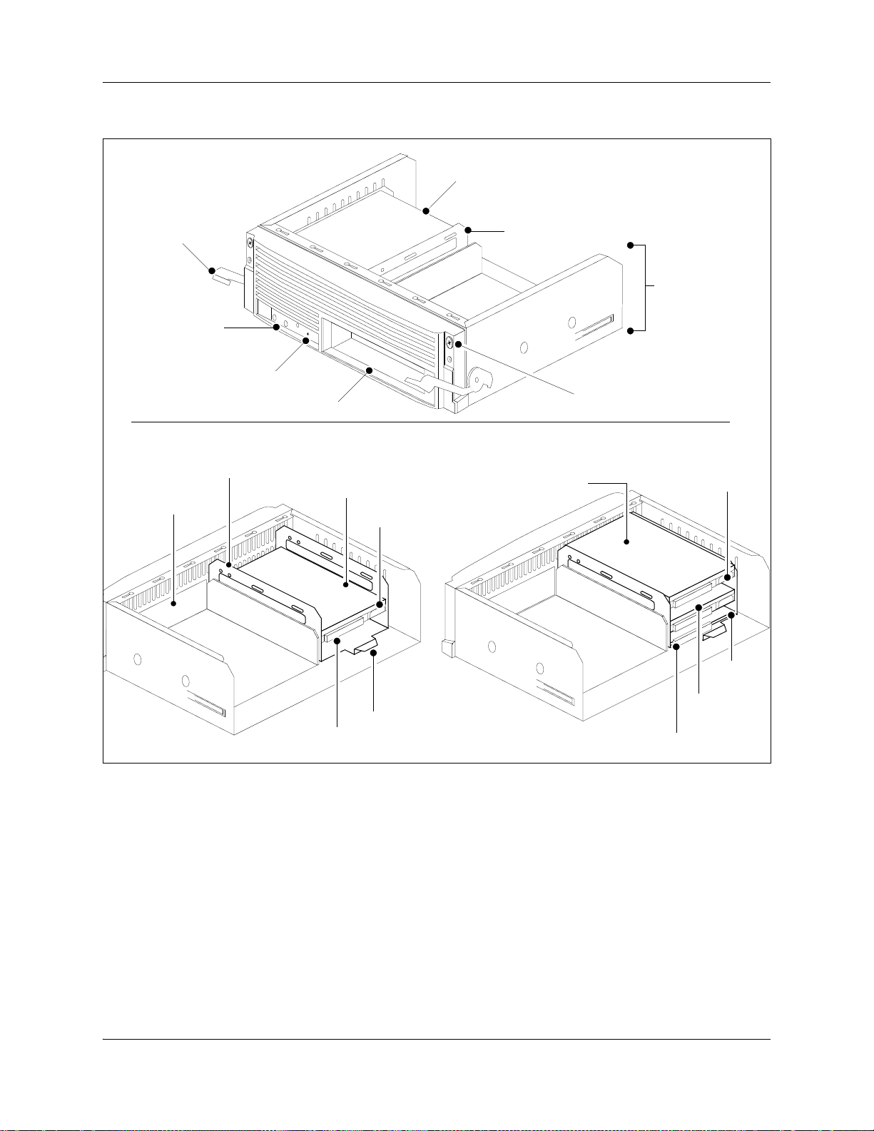
40 Chapter 2 Introducing the BCM hardware
Figure 6 Advanced function tray
Hard disk
Advanced function
tray latch
Status LEDs
(RAID only)
Buzzer reset button
(RAID only)
Reserved bay
Advanced function tray face with single hard disk
Hard disk cage
Hard disk
Reserved bay
Power supply
connector
Hard disk cage
Advanced function
tray chassis
Bezel screw
Advanced function tray RAID configuration
Primary disk
Power supply
connector
Hard disk
IDE connector
cage lift tab
BCM400 advanced function tray RAID Status LEDs
Three LEDs are located on the bezel face of the advanced function tray (see Figure 7). The LEDs
show the current state of redundant array of independent disks (RAID) hardware components.
The RAID Status LEDs indicate monitoring of the following:
• Primary hard disk activity
• Mirror hard disk activity
• RAID card status activity
N0060612N0060612
RAID
card
Mirror
disk
IDE connector

Figure 7 Advanced function tray RAID Status LEDs
Chapter 2 Introducing the BCM hardware 41
Primary Mirror
Status
Base function tray component hardware
This section describes the following base function tray components:
• “Base function tray faceplate components” on page 41
• “Base function tray internal components” on page 42
• “Main card” on page 45
• “Data networking components” on page 48
• “I/O interface card” on page 50
Base function tray faceplate components
Figure 8 illustrates the base function tray faceplate components. Table 5 describes the faceplate
components.
Alarm Reset
Figure 8 Base function tray faceplate components
System Status LEDs
Modem port
COM port
(serial port)
Reset button
Ethernet
port 2
WAN c a rd
MSC
USB port
Ethernet
port 1
BCM200/400 4.0 Installation and Maintenance Guide

42 Chapter 2 Introducing the BCM hardware
Table 5 Base function tray faceplate component descriptions
Component Description
System Status LEDs The system status display LEDs indicate the current status of the hardware
components (see “Base function tray system status display LEDs” on page 79).
Reset button The reset button restarts the BCM system.
WAN card The WAN card (field upgrade) connects the BCM system to the wide area network
(WAN). See “WAN interface card” on page 48.
Media services card (MSC) The MSC performs call processing and media processing of the voice channels for
the BCM system. See “Media services card (MSC)” on page 43.
USB (universal serial bus)
port
Modem port The modem port provides PSTN dial-up access to the BCM system.
COM port (or serial port) The COM port provides a serial connection to a laptop for maintenance purposes.
Ethernet port 2 Ethernet port 2 provides access to the internal local area network.
Ethernet port 1 Ethernet port 1 provides access to the external local area network.
The two USB ports connect USB-compatible peripherals to the BCM system.
See “Connecting through the serial port” on page 187.
Base function tray internal components
The base function tray installs in the main unit and houses the main card with the system
interfaces.
Figure 9 illustrates the base function tray layout (BCM200 configuration shown). Table 6
describes the internal components.
Figure 9 Base function tray internal components
DS256 interface
System Status LEDs
MSC
MSC mounting
screws
PEC III
slots
N0060612N0060612

Chapter 2 Introducing the BCM hardware 43
Table 6 Base function tray internal component descriptions
Component Description
System Status LEDs The system status display LEDs indicate the current status of the hardware
components (see “Base function tray system status display LEDs” on page 79).
DS256 interface The DS256 interface connects to MBM backplane DS30 connectors.
PEC III slots The PEC III slots provide connections for installing PECs.
Media services card (MSC) The MSC performs call processing and media processing of the voice channels for
MSC mounting screws These screws are used to mount the MSC in the main unit.
the BCM system. See “Media services card (MSC)” on page 43.
Media services card (MSC)
The media services card (MSC) is a peripheral component interface (PCI) card that performs call
processing and media processing of the voice channels for the BCM system, including VoIP
trunks. The MSC also offers connections for auxiliary features, including external
customer-supplied hardware for paging and music-on-hold.
Figure 10 shows the BCM200 MSC components. Figure 11 shows the BCM400 MSC
components. Table 7 describes the MSC faceplate optional connectors.
Figure 10 BCM200 MSC components
PEC III (2 slots)
DS256 interface (connect
to MBM backplane DS30
connectors)
Bracket press plate
Auxiliary ringer
Page relay
Page output
Mounting
screw
holes
PCI connector
Lanclet tab
Music-on-hold input
BCM200/400 4.0 Installation and Maintenance Guide

44 Chapter 2 Introducing the BCM hardware
Figure 11 BCM400 MSC components
PEC III (4 slots)
DS256 interface (connect
to MBM backplane DS30
connectors)
Bracket press plate
DS256 (to expansion unit)
Auxiliary ringer
Page relay
Page output
Mounting
screw
holes
PCI connector
Lanclet tab
Music-on-hold input
Table 7 MSC faceplate optional connectors
Connectors Description
DS256 connector (BCM400) The BCM expansion unit connects to the BCM main unit through the DS256 jack on
the MSC faceplate. The DS256 cable to make this connection is provided with the
purchase of a BCM expansion unit.
Auxiliary ringer jack The BCM system uses the auxiliary ringer jack to control the cadence of an auxiliary
ringer (customer supplied). You must use this output in a low current, low voltage
application only. Do not use this output for switching the auxiliary ringer directly.
Page relay jack When you use the page signal output jack to connect an external paging amplifier,
you also use the page relay jack. The page relay jack connects a floating relay contact
pair. The BCM system uses this jack to control the external paging amplifier.
Page output jack The BCM system uses the page output to connect an internally generated voice
paging signal to an external paging amplifier (customer supplied).
Music-on-hold jack The BCM system uses the music-on-hold input to connect an external music source
For directions on setting up these features, refer to “Installing optional telephony equipment” on page 181.
that supplies a signal to held lines (music-on-hold) or telephone speakers
(background music). The input source can be any available radio or music source
approved for connection to the network.
Warning: External equipment connected to the auxiliary ringer, page relay, page output,
and music-on-hold interfaces must use safety extra low voltage (SELV). All four
interfaces are (SELV) and the external equipment connected to these interfaces must be
SELV. If these interfaces are not SELV, you must use external line isolation units (LIU).
N0060612N0060612

Chapter 2 Introducing the BCM hardware 45
MSC IP call processing hardware
If your system requires a high volume of IP telephones or more IP trunks than the standard eight
trunks, you can switch a DS30 bus setting on the MSC from providing service for an MBM, to
providing digital processing service for additional IP telephones and trunks. To ensure adequate
data flow from the system, you can increase the number of PEC III cards (BCM200 can have
maximum of two cards; BCM400 can have a maximum of four).
• DS30 buses: DS30 buses contain internal communication paths. Each DS30 bus provides up
to 32 signaling channels and 32 media channels.
— Two DS30 buses are exclusively dedicated to MSC data resources. Five paths within these
buses have hard-coded applications. The other paths can be assigned to various data
applications, such as voice mail, dialup ISDN WAN, VoIP trunks, or IP telephony.
— Five DS30 buses are exclusively reserved for the MBMs.
— One DS30 bus can be switched to accommodate MBMs or more channels for IP
telephones or VoIP trunks. You control the use of this bus by using either a 2/6 or 3/5
DS30 bus split. This is set when you configure the system.
• PEC IIIs: PEC IIIs increase the digital signal processing capacity for voice mail, call center,
fax, VoIP trunks, IP telephony, and dial-up ISDN WAN features. The BCM200 system uses
one PEC III card (expandable to two). The BCM400 system uses two PEC IIIs (expandable to
four) to accommodate increased requirements for media processing.
Main card
The main card contains several field replaceable units (FRUs), such as the RAM, modem card, and
CMOS battery. A riser card, set at right angles to the main card, provides connections for the MSC
and a field-installed wide area network card (WAN). Figure 12 shows the layout of the main card
as installed in the base function tray.
BCM200/400 4.0 Installation and Maintenance Guide

46 Chapter 2 Introducing the BCM hardware
Figure 12 Main card connectors (installed in the base function tray)
PCI riser card
connectors
Modem
card
CMOS
battery
DIMM
connectors
I/O card
connector
Main card
Main card connections
The main card provides peripheral and telephony processing control for the BCM system. The
main card connects to the I/O card, system status display (SSD) card, and modem interface card.
Figure 13 shows the main card and I/O card connectors.
N0060612N0060612

Figure 13 Card connections
Chapter 2 Introducing the BCM hardware 47
Front Rear
SSD board
connector
SSD connector
Modem card
Modem card
connector
Lower PCI riser
connection to MSC
Main card
Upper PCI riser
connection to
WAN c a rd
DIMM connectors
Connect to HDD for BCM400
Main card
and I/O card
connector
I/O Card
Connect to
HDD for
BCM200
Connect to
power supply
(PSU AUX)
Connect to
redundant
fan
Connect to
single fan
Connect to
power supply
(20 pin)
Connect to
redundant power
supply status
PCI riser card
The peripheral component interface (PCI) riser card extends upward, and at a right angle, from the
main card. The PCI riser card provides a PCI for the MSC and field-installed WAN cards. Figure
14 shows the PCI riser card installed in the base function tray.
Figure 15 shows the PCI connectors without the MSC or WAN cards. Two screws at the top of the
PCI riser card attach the card to the side of the base function tray.
Figure 14 PCI riser card (installed in base function tray)
MSC
WAN c a rd
(field installable)
WAN d aug h ter car ds
PCI riser card
WAN PCI connector
MSC PCI connector
Main card/PCI riser
card connector
Main card
BCM200/400 4.0 Installation and Maintenance Guide

48 Chapter 2 Introducing the BCM hardware
Figure 15 PCI riser card connectors
WAN PCI connector
MSC PCI connector
PCI riser card
PCI riser/main card connector
Main card
Data networking components
PCI riser card mounting screws
Base
function
tray - front
The data networking components connect the BCM system to the WAN.
WAN interface card
The network interface card (NIC) uses a T1 interface and sync port that connects the BCM system
to the WAN. The WAN card is available as a field replaceable unit. For further information on
removal, installation, and initialization, refer to “Replacing cards” on page 307.
The international WAN card version (Europe, Middle East, Africa [EMEA]) connects to a
channelized T1 TDM circuit with an X.21 or V.35 interface (see Figure 16 on page 49).
The dual V.35 WAN card version connects to channelized T1 TDM circuits using two V.35
interfaces (North America) (see Figure 17 on page 49).
The North American WAN card version connects to a channelized T1 TDM circuit with an
integrated T1 DSU/CSU or a V.35 interface, or both (see Figure 18 on page 49).
N0060612N0060612

Figure 16 WAN interface card (international version)
Daughter cards
PCI clamp
press plate
X.21 DB25 female
connector (WAN1)
V.35 DB25 female connector (WAN2)
Figure 17 Dual V.35 WAN interface card
Daughter cards
PCI clamp
press plate
Chapter 2 Introducing the BCM hardware 49
WAN c ar d
PCI connector
WAN c a rd
PCI connector
V.35 DB25 female connector (WAN1)
V.35 DB25 female connector (WAN2)
Figure 18 WAN interface card (North American version)
Daughter cards
PCI clamp
press plate
T1 CSU connector (WAN1)
V.35 DB25 female connector (WAN2)
WAN c a rd
PCI connector
BCM200/400 4.0 Installation and Maintenance Guide

50 Chapter 2 Introducing the BCM hardware
Modem card
The V.92 (or V.90) modem connects the BCM system to the public switched telephone network
(PSTN), enabling the BCM system to send and receive data. The modem card is standard on North
American systems, while it is optional for APAC and EMEA. The modem kit consists of a modem
card, RJ-11 interface, and connector cable. For further information on installation and removal, see
“To install a modem card” on page 317 and “To remove the modem card” on page 315.
Figure 19 shows the modem components.
Use the modem connection to:
• manage the BCM system from a different location
• provide dial-up backup for a WAN card
Figure 19 Modem card and interface
Modem card RJ-11 card interface
To main card modem
socket connector
Modem card
pin guide
RJ-11 connector
(exposed on base
function tray face)
2-pin connector
Main card connector
Base function tray
mount points
I/O interface card
The I/O interface card provides a signal junction between the base function tray, hard disk, power
supply, and cooling system. Figure 20 shows the I/O interface card and connections.
N0060612N0060612

Figure 20 I/O interface card connectors
PSU status - RPS output
signalling connector
BCM200 MSC guide bracket
Primary IDE
controller (IDE0)
Base function
tray connector
Chapter 2 Introducing the BCM hardware 51
Fan 2 connector
Fan 1 connector
20-pin power
supply connector
I/O Card
PSU AUX connector
BCM expansion unit (BCM400 only)
In addition to a main unit, the BCM400 system can have one expansion unit. The expansion unit is
not compatible with the BCM200 system. The BCM expansion unit contains six additional bays
for MBMs.
The supplied DS256 cable is 5 m (16 ft.) long and connects into a DS256 port on the MSC of the
main unit, and into a DS256 port on the center panel of the expansion unit (see Figure 21). Use of
any other cable is not supported. See “Installing an expansion unit” on page 103 for more
information on installing a expansion unit.
Note: The number of MBMs that you can install is determined by the number of DS30
buses required by the MBMs and the number of buses available.
Refer to Chapter 8, “Installing a media bay module (MBM),” on page 107.
Secondary IDE
controller (IDE1)
BCM200/400 4.0 Installation and Maintenance Guide

52 Chapter 2 Introducing the BCM hardware
Figure 21 BCM expansion unit connected to BCM400 main unit
BCM400 main unit
DS256 port
BCM expansion unit
NEEd
DS256 port
MBM bays and backplane
The number and configuration of the MBMs depend on the number of bays available in the main
unit and DS30 system resources. The BCM200 main unit provides two MBM bays. The BCM400
main unit provides four MBM bays.
All MBM bays must contain either an MBM or an MBM filler blanking plate. Fill unpopulated
MBM bay openings in the main unit with the MBM filler blanking plates (see Figure 22).
Figure 22 MBM filler blanking plate
Filler blanking plate
face
Locking clip
The MBMs slide into the MBM bays and lock into place. Pull on the MBM ejector to release the
MBM or filler blanking plate. The MBM or filler blanking plate partially ejects from the bay. Slide
the MBM out of the bay to remove it from the main unit.
N0060612N0060612

Chapter 2 Introducing the BCM hardware 53
The MBM backplane provides the MBM component interface to the power supply and main card.
The MBM backplane mounts at the rear of the MBM bays and is a non-replaceable component.
Figure 23 illustrates the BCM200 MBM backplane and connectors.
Figure 23 BCM200 MBM backplane
Front view Rear view
MBM backplane
connectors
Figure 24 illustrates the BCM400 MBM backplane and connectors.
Figure 24 BCM400 MBM backplane
MBM backplane
connector to MSC
MBM backplane
connector to power
supply
Front view
MBM backplane
connectors
Media bay modules (MBMs)
The BCM system is modular. You can increase the capacity of the system by adding more media
bay modules (MBMs). Each BCM allocates a maximum of six DS30 buses to the MBMs. The
number of MBMs that can be added to your system is determined by the number of media bays
that are open, combined with the number of DS30 buses each component uses.
Rear view
MBM backplane
connector to MSC
MBM backplane
connector to power
supply
BCM200/400 4.0 Installation and Maintenance Guide

54 Chapter 2 Introducing the BCM hardware
If your system requires many IP lines or trunks, you can reduce the number of DS30 buses that are
assigned to MBMs and increase the number of buses available to IP telephones. This is known as a
3/5 DS30 bus split. In this case, you only have five DS30 buses available for use by the MBMs.
Refer to “Understanding DS30 numbers” on page 111 for more information.
Warning: Changing the DS30 bus split
If you change the bus split from 2/6 (default) to 3/5 after the system is initialized, any
module set to DS30 bus 7 or requiring the use of bus 7 becomes inoperable.
If you change the bus split from a 3/5 split to a 2/6 split after the system is initialized, all
data is lost, and all optional applications must be reinstalled and reconfigured.
Bus 7 must be
enabled prior to converting from a 2/6 to 3/5 split.
Figure 25 Telephony hardware components
Refer to “Media bay module availability” on page 361
and “FEM MBM–Norstar trunk cartridge
combinations” on page 362 to determine which MBMs
and which types of trunk lines are available in your
location.
The MBMs connect with external devices to implement various types of voice trunks and
extensions. Install the MBMs in the MBM bays in the BCM200 or BCM400 main units and the
BCM expansion unit.
CTM 4
1Aux 2 3 4
1234 1234
StatusPower
“Telephones and adapters”
on page 75
DSM 16+
“Trunk media bay modules
(MBMs)” on page 55
“Station media bay modules
(MBMs)” on page 59
“Specialized media bay
modules (MBMs)” on page
MBMs have LEDs on the faceplate. For information on MBM LEDs, see “Viewing the BCM
system LEDs” on page 79.
The back of the MBM has a single connector that provides signaling channels, media channels,
and power to the MBM. This connector plugs into the MBM backplane in the main unit or
expansion unit. Some MBMs also have a cooling fan that runs off the MBM power source. Figure
26 shows the rear views of the two types of MBMs.
N0060612N0060612
Note: Refer to “Media bay module availability” on page 361 to determine which
MBMs and which types of trunk lines are available in your location.

Figure 26 MBM connectors (rear view)
Chapter 2 Introducing the BCM hardware 55
Signaling, media, and
power connector
Signaling, media, and
power connector
Cooling fan
This section provides information on the following telephony MBMs:
• “Trunk media bay modules (MBMs)” on page 55
• “Station media bay modules (MBMs)” on page 59
• “Specialized media bay modules (MBMs)” on page 64
Trunk media bay modules (MBMs)
You install the trunk MBMs in the BCM main unit or the BCM expansion unit. Trunk MBMs
connect telecommunications lines to the BCM system.
The type of MBM you install is determined by:
• which lines are available from your telephone service provider
• what lines you require for the types of telephones you want to use
• budget considerations
Table 8 lists the types of trunk MBMs that are available for the BCM system.
Table 8 Trunk MBMs (Sheet 1 of 2)
MBM What it does Special notes
DTM
(see “Digital trunk media bay
module” on page 56)
CTM4/CTM8
(see “Caller ID trunk media bay
module” on page 57)
Connects digital public switched
telephone lines to the BCM system.
Connects a maximum of four (CTM4) or
eight (CTM8) analog public switched
telephone lines to the BCM system.
BCM200/400 4.0 Installation and Maintenance Guide
Install in the BCM main unit only.
DTMs do not function if installed in the
BCM expansion unit.

56 Chapter 2 Introducing the BCM hardware
Table 8 Trunk MBMs (Sheet 2 of 2)
MBM What it does Special notes
ISDN BRI
(see “Basic rate interface media
bay module” on page 58)
GATM4/GATM8
(see “Global analog trunk media
bay module” on page 58)
ADID4/ADID8
(see Analog direct inward dialing
media bay module on page 59)
Note: Refer to “Market profile attributes” on page 361 for supported market profiles.
Connects a maximum of four ISDN BRI
S/T interfaces.
Connects either four (GATM4) or eight
(GATM8) analog public switched
telephone lines to the BCM system.
Connects either four (ADID4) or eight
(ADID8) analog DID interfaces.
Digital trunk media bay module
The digital trunk media bay module (DTM) connects to a standard digital PSTN T1/fT1, E1/fE1,
or PRI ISDN line using either a digital or PRI line. The DTM also supports DASS2, DPN22,
Q.SIG, and MCDN over ISDN:
• On North American BCM systems, the DTM connects a T1 or PRI circuit to the BCM system;
T1 circuits provide 24 digital channels to the PSTN, while PRI circuits provide 23 digital
channels to the PSTN.
• On International BCM systems, the DTM connects an ETSI ISDN (E1) or PRI (EI) circuit to
the BCM system, providing a maximum of 30 digital channels to the PSTN.
Warning: Install DTMs in the BCM main unit only. DTMs do not function if
installed in the BCM expansion unit.
If there are no empty MBM bays in the BCM main unit, move MBMs to the
expansion unit to provide space for the DTMs.
The front bezel of the DTM has an RJ-48C connector that connects the DTM to the service
provider connection point. The faceplate also has a set of monitor jacks you can use to monitor the
span.
There are six additional LEDs on the front of the DTM. For information about these additional
LEDs, refer to “DTM LEDs” on page 82.
Figure 27 shows the DTM module interfaces.
N0060612N0060612

Chapter 2 Introducing the BCM hardware 57
Figure 27 DTM faceplate
Monitor jacks RJ-48C digital
Tip: You can install a maximum of three DTM modules in the BCM main unit, depending
on the available buses.
Caller ID trunk media bay module
There are two Caller ID trunk media bay modules (CTM):
telephone line
connector
• CTM4
The CTM4 connects a maximum of four analog calling line ID (CLID) interfaces to the BCM
system through four RJ-11 jacks on the MBM faceplate. These jacks are labeled Line 1,
Auxiliary, Line 2, Line 3, and Line 4. The auxiliary jack connects to Line 1.
• CTM8
The CTM8 provides eight analog CLID interfaces to the BCM system through eight RJ-11
jacks on the MBM faceplate. Each jack also supports disconnect supervision. There are two
auxiliary jacks on this MBM which connect to Line 1 and Line 5.
The auxiliary ports enable you to connect to a V.92 or V.90 modem, fax machine, or analog
telephone. When the auxiliary device is active, the BCM system disables the associated line.
Conversely, when the line is active, the auxiliary port line is disabled. When you connect an
analog telephone to the auxiliary port, you can use it as an emergency telephone because this line
remains active during a power outage.
Figure 28 shows the front of the CTM4 and CTM8.
BCM200/400 4.0 Installation and Maintenance Guide

58 Chapter 2 Introducing the BCM hardware
Figure 28 CTM4 and CTM8 module faceplate LEDS and connectors
CTM 4
Power LED
Status LED
Line 1
Aux
Line 2
Line 3
Line 4
Basic rate interface media bay module
The basic rate interface media bay module (BRIM) connects a maximum of four BRI ISDN loops
to the BCM system. The BRIM only recognizes the T-interface used in European networks. To use
the BRIM with the U-interface, typical in North American networks, you require an external NT1
box to convert the U-interface to a T-interface.
1Aux 2 3 4
CTM4
Front View
Line 1
Auxiliary port
Auxiliary port
Line 5
CTM 8
87 6Aux5
1Aux 2 3 4
CTM8
Each BRI ISDN loop you connect adds two telephone lines to the BCM system. Therefore, each
BRIM adds a maximum of eight lines to the BCM system through the four RJ-48C jacks on the
faceplate. The LEDs beside each RJ-48C jack are on when the ISDN line is active. Figure 29 on
page 58 shows the BRIM faceplate LEDs and connections.
Figure 29 BRIM faceplate
Global analog trunk media bay module
The global analog trunk media bay module (GATM) provides an interface for four or eight analog
public switched telephone network (PSTN) lines. The GATM supports both pulse and tone
dialing, as well as caller ID and disconnect supervision in selected markets throughout the world.
The GATM uses an RJ-21 connector as the trunk interface. Figure 30 shows the GATM faceplate
LEDs and RJ-21 connector. The GATM is available either in four-port (GATM4) or eight-port
(GATM8) configurations.
N0060612N0060612

Chapter 2 Introducing the BCM hardware 59
Figure 30 GATM faceplate
Analog direct inward dialing media bay module
The analog direct inward dialing (ADID) MBM provides an interface for four or eight analog
public switched telephone network (PSTN) lines. The ADID MBM supports both pulse and tone
dialing as well as disconnect supervision, and direct inward dialing call progress signaling as
described in standard TIA-464C.
The ADID MBM uses an RJ-21 connector for trunk connections. The figure ADID faceplate on
page 59 shows the ADID faceplate LEDs and connectors. The ADID is available either in
four-port (ADID4) or eight-port (ADID8) configurations.
Figure 31 ADID faceplate
Station media bay modules (MBMs)
Station (MBM) connect telephones and analog telecommunication devices to the BCM system.
Table 9 lists the available station MBMs.
Table 9 Station MBMs (Sheet 1 of 2)
MBM What it does Special notes
DSM16(+)/DSM32(+)
(see “Digital station media bay module”
on page 60)
4x16
Combination of a CTM4 and a DSM16
(see “4x16 media bay module” on page
61)
ASM/ASM8
(see “Analog station media bay modules”
on page 61)
Connects a maximum of 16 (DSM16+) or
32 (DSM32+) digital telephones to the
BCM system.
Connects a maximum of four analog
public switched telephone lines to the
BCM system.
Also connects a maximum of 16 digital
telephones to the BCM system.
Connects a maximum of eight analog
devices to the BCM system.
BCM200/400 4.0 Installation and Maintenance Guide

60 Chapter 2 Introducing the BCM hardware
Table 9 Station MBMs (Sheet 2 of 2)
MBM What it does Special notes
ASM8+/GASM
(see “Analog station media bay modules”
on page 61)
Note: Refer to “Market profile attributes” on page 361 for supported regions.
Connects a maximum of eight analog
devices to the BCM system.
The GASM provides the following
additional services: caller ID, pass
through, message waiting indication, and
disconnect supervision at the telephone.
The GASM also allows you to download
new firmware.
Digital station media bay module
The digital station media bay modules (DSM) support digital telephones on the BCM system. This
section describes the DSM16(+) and DSM32(+) MBMs (see Figure 32).
The DSMs have the following characteristics:
• DSM16(+) — supports 16 digital telephones through one RJ-21 connector. Set the double
density switch to enable the DSM to carry 16 extensions over a half DS30 bus. If required,
install a second DSM16(+) and set the double density switch to occupy the second half of the
DS30 bus to expand the number of extensions to 32.
• DSM32(+) — supports 32 digital telephones through two RJ-21 connectors. A DSM32(+)
operating in single-density mode occupies two DS30 buses. Set the double density switch to
enable the DSM to carry 32 extensions over a single DS30 bus.
Note: Devices that share a DS30 bus must be similar. Use two DSM16(+) module
in double density mode on a single DS30 bus. Do not mix a DSM16(+) module
with a DSM32(+) module over a single DS30 bus.
Figure 32 DSM faceplate LEDs and connectors
DSM 16(+)
DSM 32(+)
N0060612N0060612

Chapter 2 Introducing the BCM hardware 61
4x16 media bay module
The 4x16 media bay module (MBM) provides both analog trunk connections and connections to
digital telephones. The 4x16 MBM provides connections for four analog trunk lines and 16 digital
telephones. Each of the four analog trunk lines support caller ID and disconnect supervision. An
auxiliary port next to the Line 1 port enables you to use an analog telephony device, such as a
modem, fax, or telephone, to share the trunk.
Figure 33 shows the 4x16 MBM. The 4x16 MBM has one RJ-21 connector and five RJ-11
connectors on the faceplate.
Figure 33 4x16 faceplate LEDS and connectors
Analog station media bay modules
The analog station media bay modules (ASM, ASM8, ASM8+, and GASM8) can connect to a
maximum of eight analog telecommunication devices. These devices are standard analog
telephones, cordless telephones, fax machines, answering machines, or modems. The maximum
speed for a modem connection is 28.8 kbit/s.
In addition to ASM8 features, the ASM8+ and GASM8 offer the following features:
• Visual Message Waiting Indicator (VMWI) — LED indicates to the end user that a message is
waiting.
• Disconnect supervision (Open Switch Interval [OSI] as per EIA/TIA 464) — indicates to the
attached device, in an established communication, that the connected device should release the
call (see disconnect supervision note).
• Caller ID — provides the name, phone number, and other information about the caller to the
end user at the start of the call.
• Firmware downloading capability — allows the system to upgrade the ASM8+ and GASM8
firmware at customer sites.
• Enhanced ringing capability — ASM8+ and GASM8 provide a ringing voltage of 2 REN/65 V
rms per port.
• Calling line identification (CLID)
• The GASM8 is designated as an ONS (on-premise station) port.
BCM200/400 4.0 Installation and Maintenance Guide

62 Chapter 2 Introducing the BCM hardware
Disconnect supervision note: The central office disconnects the call after the
ASM8+ provides an open switch interval (OSI) to the off-hook station of 850 ms
(TIA/EIA 464 section 5.4.10.2.4; minimum is 600 ms) as a disconnect signal. If
the station remains on-hook after the disconnect signal, the ASM8+ disconnects
the station equipment from the network without returning a tone to it (TIA/EIA
464 section 5.4.10.2.5[1]). After the station equipment goes on-hook, the ASM8+
station interface is restored to on-hook (idle).
It is important to ensure that the device, application, or interface card connected to
an ASM8+ station interface conform to these on-hook and off-hook conditions.
The ASM, ASM8, ASM8+, and GASM8 each have one RJ-21 connector on the faceplate. Figure
34 on page 62 shows the GASM8.
Figure 34 GASM8 faceplate LEDs and connectors
The ringer equivalency number (REN) per port for ASM8 is 1; the REN for ASM8+ and GASM8
is 2.
Note: The termination of the analog interface can consist of any combination of devices,
subject only to the requirement that the sum of the RENs of all the devices does not exceed
the REN of the interface to which the device is connected.
Table 10 shows the specifications for ATA2, ASM8, ASM8+, GASM8, and global analog station
interface (GASI).
Table 10 ATA2, ASM8, ASM8+, GASM, and GASI analog device specifications (Sheet 1 of 2)
Specification ATA2 ASM8 ASM8+ GASM8 GASI
Ringing frequency
(North America)
Ringing frequency
(Europe)
Ringing voltage (North
America)
Ringing voltage
(Europe)
20 Hz ± 1 Hz 20 Hz ± 1 Hz 20 Hz ±1 Hz 20 Hz ±1 Hz 20 Hz ±1 Hz
± 1 Hz 25 Hz ± 1 Hz 25 Hz ± 1 Hz 25 Hz ± 1 Hz 25 Hz ± 1 Hz
25 Hz
80 V rms
75 V rms +/10%
± 10% 55 V rms ± 10% 65 V rms ± 10% 65 V rms ± 10% 65 V rms ± 10%
N/A 65 V rms
± 10% 65 V rms ± 10% 65 V rms ± 10%
N0060612N0060612

Chapter 2 Introducing the BCM hardware 63
Table 10 ATA2, ASM8, ASM8+, GASM, and GASI analog device specifications (Sheet 2 of 2)
Specification ATA2 ASM8 ASM8+ GASM8 GASI
Loop current 20 mA minimum 20 mA minimum 20 mA minimum 20 mA minimum 20 mA minimum
Battery feed voltage -48 V dc
FIC code OL13ABC N/A N/A N/A N/A
Ringer equivalency
number
ATA2 to BCM loop
resistance (cable only)
Analog loop resistance
on terminal side for
voice applications
(cable only)
Analog loop resistance
on terminal side for
data applications
(cable only)
Input impedance at tip
and ring
Return loss > 20 dB for 200
Insertion loss on an
internal call
Insertion loss on an
external call
31222
135 ohms
(800 m of
0.5-mm wire or
2600 ft of 24
AWG wire)
1300 ohms
(7200 m of
0.5-mm wire or
26000 ft of 24
AWG wire)
200 ohms (1231
m of 0.5-mm
wire or 4000 ft of
24 AWG wire)
600 ohms 600 ohms 600 ohms 600 ohms 600 ohms
to 3400 Hz
(when
terminated with
600 ohms)
ATA2 to BCM
loss 3.0 dB
dB
ATA2 to BCM
loss 2.2 dB +/-
1.0 dB; BCM to
ATA2 loss 0.5 dB
± 1.0 dB
MWI type (see Note) Stutter tone Stutter tone Stutter tone/
Disconnect
supervision types
Note: The MWI type depends on the country profile, and the MWI voltage shown is a maximum value.
N/A N/A OSI EIA/TIA 464
± 10% -48 V dc ± 10% -29 V dc ± 10% -48 V dc ± 10% -48 V dc ± 10%
N/A N/A N/A N/A
250 ohms (1538
m of 0.5-mm
wire or 5000 ft of
24 AWG wire)
250 ohms (1538
m of 0.5-mm
wire or 5000 ft of
24 AWG wire)
> 20 dB for 200
to 3400 Hz
(when
terminated with
600 ohms)
ATA2 to BCM
loss 3.0 dB
± 0.5
dB
ASM to BCM
loss 3.0 dB +/-
1.0 dB; BCM to
ASM loss 0.5 dB
± 1.0 dB
200 ohms (1231
m of 0.5-mm
wire or 4000 ft of
24 AWG wire)
200 ohms (1231
m of 0.5-mm
wire or 4000 ft of
24 AWG wire)
> 20 dB for 200
to 3400 Hz
(when
terminated with
600 ohms)
ATA2 to BCM
loss 3.0 dB
± 0.5
dB
ASM to BCM
loss 3.0 dB +/-
1.0 dB; BCM to
ASM loss 0.5 dB
± 1.0 dB
/ Voltage MWI
(CO: 120 V)
section
4.5.10.2.4/
4.5.10.2.5.1
200 ohms (1231
m of 0.5-mm
wire or 4000 ft of
24 AWG wire)
200 ohms (1231
m of 0.5-mm
wire or 4000 ft of
24 AWG wire)
> 20 dB for 200
to 3400 Hz
(when
terminated with
600 ohms)
ATA2 to BCM
loss 3.0 dB
± 0.5
dB
ASM to BCM
loss 3.0 dB +/-
1.0 dB; BCM to
ASM loss 0.5 dB
± 1.0 dB
Stutter tone/
Reverse polarity/
Voltage MWI
(CO: 120 V)
OSI EIA/TIA 464
section
4.5.10.2.4/
4.5.10.2.5.1
200 ohms (1231
m of 0.5-mm
wire or 4000 ft of
24 AWG wire)
200 ohms (1231
m of 0.5-mm
wire or 4000 ft of
24 AWG wire)
> 20 dB for 200
to 3400 Hz
(when
terminated with
600 ohms)
ATA2 to BCM
loss 3.0 dB
± 0.5
dB
ASM to BCM
loss 3.0 dB +/-
1.0 dB; BCM to
ASM loss 0.5 dB
± 1.0 dB
Stutter Tone/
Reverse polarity/
Voltage MWI
(PBX: 90 V)
N/A
± 0.5
BCM200/400 4.0 Installation and Maintenance Guide

64 Chapter 2 Introducing the BCM hardware
Specialized media bay modules (MBMs)
This section describes the MBMs that perform a specific job outside of the trunk and station MBM
descriptions (see Table 11).
Table 11 Specialized MBMs
Module type What it does Special notes
FEM
(see “Fiber expansion
media bay module” on
page 64)
DDIM
(see “Digital drop and
insert MUX” on page
64)
Connects a maximum of six Norstar expansion
units.
Enables a BCM system to share its connection to a
universal T1 network with a LAN.
Fiber expansion media bay module
The fiber expansion media bay module (FEM) connects a maximum of six Norstar MBMs to the
BCM system. These connections provide a quick way to upgrade a Norstar system to a BCM
system.
The front bezel of the FEM has six connectors. These connections are made using fiber cables
between the FEM module and the Norstar expansion unit.
Figure 35 shows the front of the FEM module. Each enabled port consumes one DS30 bus.
Figure 35 FEM faceplate LEDs and connectors
FEM
4
5
6
The switches on the FEM are used to
turn fiber ports on and off. The FEM
does not work correctly if you set these
switches using the rules used for other
MBMs.
Digital drop and insert MUX
The digital drop and insert MUX media bay module (DDIM) enables a BCM system to share its
connection to a universal T1 network with a local area network (LAN) to provide a combination of
voice and data channels.
The DDIM:
N0060612N0060612
Port 4
Power LED
Status LED
Port 1
Port 5
Port 2
Port 6
Port 3
321
Front view

• provides the functionality of a DTM (T1 digital lines only)
• splits the incoming T1 line so that some of the lines are used for voice traffic and some of the
lines are used for data traffic
• provides either the channel service unit (CSU) or data service unit (DSU) functionality to
support connections to data terminal equipment (DTE), such as a router or a bridge
• connects to network devices that support V.35 interfaces
• provides end-to-end transparent bit service
• supports loopbacks between the BCM system and the internal BCM components, and between
the BCM system and digital terminal equipment
Figure 36 shows the DDIM faceplate LEDs and connectors.
Figure 36 DDIM faceplate LEDs and connectors
Chapter 2 Introducing the BCM hardware 65
Data module serial port
Power LED
Status LED
In Service LED
Loopback test LED
Continuity loopback
Receive LEDs
Tra n sm i t LEDs
BCM400 expansion gateway
The BCM400 expansion gateway is available in standard and redundant configurations for
BCM400 systems only.
The BCM400 expansion gateway kit (North America only) consists of a BCM400 main unit and
enough VoIP gateway trunk authorization codes to enable 48 ports of VoIP trunks. The BCM400
expansion gateway, combined with the BCM400 host system, provides a maximum of 192 TDM
sets, instead of 160, while communicating to the PSTN through TDM trunks on the expansion
gateway. The VoIP trunks connect the two systems and allow the BCM400 expansion gateway to
tandem from IP trunks to the PSTN/TDM trunks (see Figure 37 on page 66).
RxDTxD RTS CTS DCD DSR TM10101
Loopback
RJ-48C digital telephone line
connector
The addition of a second BCM400 expansion gateway provides up to two T1 PSTN trunks. This
releases enough system resources on the host BCM400 main unit for the addition of 64 digital
telephones.
BCM200/400 4.0 Installation and Maintenance Guide

66 Chapter 2 Introducing the BCM hardware
Figure 37 BCM400 expansion gateway configuration
Pr MMAla
Host:
BCM main unit
and
expansion unit
All stations are
connected to
the Host
IP trunk
BCM400 expansion
gateway
BCM components
Refer to the following sections for descriptions of the BCM components:
• “BCM power supply”
• “BCM400 redundant power supply”
• “Power supply adapter cord (international users)”
• “Uninterruptable power supply”
• “Hard disk”
• “RAID upgrade kit”
• “Cooling fan”
BCM power supply
The BCM200 main unit and the BCM400 main unit (standard) use a switched power supply.
Internal cabling routes to the I/O card, media bay backplane, and hard disk. External cabling
extends to the line power supply outlet (see Figure 38 and Figure 39).
Pr MMAla
PSTN
Two PSTN trunks
on expansion
gateway
Figure 38 BCM200 and BCM400 (standard) power supply (rear view)
Rear view
Fan
N0060612N0060612
On/off switch
AC power connector

Figure 39 Standard power supply connectors
Connector Configuration for
Standard Sparkle Power Supply New Lengths
525mm MBM Back plane
Chapter 2 Introducing the BCM hardware 67
Purpose and Notes
525mm
500mm to first,
+50mm to next,
+100mm to last
(total 650mm)
tie wrapped
every 5cm
430mm to first
(right angle) ,
+150mm to
next (total
580mm)
480mm
480mm
MBM Back plane for BCM400, not required for BCM200
Hard disk cage, extra connectors to be tucked under the
hard disk
Reserved for future use
I/O Card
I/O Card
BCM400 redundant power supply
The BCM400 redundant power supply (RPS) is available as a field replaceable unit (FRU) or as
part of the BCM400 RFO. The redundant power supply consists of two power supply modules and
a power supply unit (see Figure 40 and Figure 41). The power supply modules are interchangeable
and can be exchanged one at a time during power-on conditions.
BCM200/400 4.0 Installation and Maintenance Guide

68 Chapter 2 Introducing the BCM hardware
Figure 40 BCM400 redundant power supply and modules
Power supply module
removed from the redundant
power supply unit
Figure 41 BCM400 redundant power supply connectors
Conne ct or Configura ti on f or
Redunda nt Spa rkle Power Supply
Cable Le ngths and
Markings
550mm (P2)
550mm (P3)
325mm to first
(P4), +50mm to
next (P5),
+100mm to last
(P6) (total 475mm)
340mm to first
(P7)(right a ngle) ,
+1 5 0mm to nex t
(P8) (total 490mm)
Route to Media bay backplane 1: Tie any slack at
the connector (behind the MBM).
Route to Media bay backplane 2: Tie any slack at
the connector (behind the MBM).
To hard disk: Tie any slack at the power supply. Tuck
any loose connectors under the hard disk cage.
Unused. Tie to the center of the hard disk cage.
Route to the I/O card.
Power supply module
inserted in the
redundant power
supply unit
Purpose and Notes
In addition, international (non-North American) users require a power supply adapter cord for
each main unit and expansion unit.
N0060612N0060612
515mm (P1)
Route to the I/O card.
515mm (P9)
Route to the I/O card.
515mm (PA)
Unused
300mm (PB)

Chapter 2 Introducing the BCM hardware 69
Power supply adapter cord (international users)
The power supply adapter cord is for international (non-North American) BCM users. It connects
to the power supply on one end and to the (C-14) BCM power bar on the other end.
You require one power supply adapter cord for each power supply you want to connect to the
power bar.
Uninterruptable power supply
An uninterruptable power supply (UPS) is an optional device that maintains continuous operation
during power interruption or failure conditions. The UPS provides power source monitoring and
battery backup activation so that critical BCM functionality is maintained.
In a power failure situation, the UPS provides sufficient time to either correct the problem or
activate a contingency plan to sustain services. The UPS is configured to perform a graceful
shutdown of the BCM 2 minutes before the UPS battery power is drained.
The BCM system supports American Power Conversion (APC) UPS devices that use a USB
control interface. These include the APC UPS-Smart family (for example, UPS-Smart 750,
UPS-Smart 1000) and UPS-Back family (for example, UPS-Back 500 ES, UPS-Back 350 ES).
The UPS control software enables the configuration of various operational settings.
Note: For the UPS to function correctly, connect the UPS before the BCM system
is powered up. If you connect a UPS to a running system, the UPS will not
function.
In BCM 4.0 the serial interface is not supported for UPS connectivity. Only the
USB interface supports UPS connectivity.
On BCM systems with more than one unit, the power supplies for all of the units must be
connected to a single UPS.
The UPS feature is supported in all markets (110~120V and 220~240V power standards).
Hard disk
The BCM200 main unit and the BCM400 main unit (standard) contain a single hard disk and hard
disk bracket (see Figure 42 and Figure 43).
BCM200/400 4.0 Installation and Maintenance Guide

70 Chapter 2 Introducing the BCM hardware
Figure 42 BCM200 main unit hard disk and bracket
Front view
Hard disk bracket
Hard disk
Connector
Figure 43 BCM400 main unit hard disk and bracket
Front view
Hard disk bracket
Hard disk
Rear view
Hard disk bracket lift tab
Rear view
RAID upgrade kit
The BCM200 main unit and the BCM400 main unit (standard) can contain a redundant array of
independent disks (RAID). The RAID upgrade kits have a single hard disk (mirror) and RAID
controller card. Use your current hard disk (from the single disk system) as the primary hard disk.
When the RAID upgrade is installed, the data from the primary hard disk is written to the mirror
hard disk. The dual hard disk configuration provides one-fault tolerance capability.
N0060612N0060612
Hard disk bracket lift tab

Chapter 2 Introducing the BCM hardware 71
The RAID card has three ribbon cable connectors. The hard disk connectors are mounted on the
right and left sides of the RAID controller card. The third ribbon cable connection, mounted at the
rear of the card, connects to the primary IDE connector on the I/O card (see Figure 44).
Figure 44 RAID upgrade kit (BCM400 main unit standard installation shown)
Front view
Primary hard disk
Mirror hard disk
RAID controller card
Rear view
Note: Reverse RAID
bracket installation
for BCM200. Lift tab
is on opposite end.
RAID card
Status LEDs
Primary hard disk
RAID connector
Mirror hard disk
RAID connector
RAID bracket
Mirror hard disk ribbon
cable connector (primary
hard disk connector on
opposite side)
Reset button
Primary hard disk
ribbon cable connector
IDE connector
Hard disk
bracket lift tab
Power supply
connectors
Cooling fan
The BCM200 main unit and BCM400 main unit (standard) have a single cooling fan, while the
BCM400 main unit RFO configuration has two fans. Figure 45 illustrates a cooling fan and
connectors.
The cooling fan mounts in the back of the BCM200 main unit. The cooling fans mount on a
removable panel in the back of the BCM400 main unit.
BCM200/400 4.0 Installation and Maintenance Guide

72 Chapter 2 Introducing the BCM hardware
Figure 45 Cooling fan
Field replaceable units (FRU)
Use Table 12 to Table 17 as a reference when you need to order, replace, or install component
hardware. The tables provide references to the component description and installation procedures.
Mount holes
I/O card fan
connector
Note: The product engineering code can change over time; consult the catalog for
the latest information.
Table 12 Card field replaceable units
Component description FRU description Installation procedure
Modem card “Modem card” on page 50 “To install a modem card” on page
317
Media services card “Media services card (MSC)” on page 43“To install the media services card
Media services PEC III “MSC IP call processing hardware”
on page 45
WAN interface card with CSU/V.35
(North America only)
Dual V.35 WAN interface card “WAN interface card” on page 48 “Installing the WAN card” on page
WAN interface card with CSU/V.35/
X.21 (International only)
256MB memory module “Main card” on page 45 “To install a DIMM card” on page 326
“WAN interface card” on page 48 “Installing the WAN card” on page
“WAN interface card” on page 48 “Installing the WAN card” on page
(MSC)” on page 314
“To install a PEC” on page 323
310
310
310
N0060612N0060612

Chapter 2 Introducing the BCM hardware 73
Table 13 Chassis field replaceable units
Component description FRU description Installation procedure
Base function tray “Base function tray component
hardware” on page 41
Wall-mount kit N/A “Installing the main unit on the wall”
BCM field redundancy upgrade kit “BCM400 main unit” on page 36 “Upgrading to a redundant power
“To install the base function tray” on
page 244
on page 98
supply” on page 294
“Replacing the hard disk” on page
261
“Replacing or installing a cooling fan”
on page 331
Table 14 Hard drive field replaceable units
Component description FRU description Installation procedure
BCM hard disk, programmed (20GB) “Hard disk” on page 69 “Replacing the hard disk” on page
261
BCM RAID upgrade kit “RAID upgrade kit” on page 70 “Replacing the hard disk” on page
BCM replacement blank hard drive “Hard disk” on page 69 “Replacing the hard disk” on page
261
261
Table 15 Power supply field replaceable units
Component description FRU description Installation procedure
BCM uninterruptable power supply “BCM power supply” on page 66 “Replacing a standard power supply”
BCM400 redundant power supply
module (single)
“BCM400 redundant power supply”
on page 67
on page 283
“Upgrading to a redundant power
supply” on page 294
Table 16 Cooling fan field replaceable units
Component description FRU description Installation procedure
BCM400 cooling fan (4-wire base
unit)
BCM expansion unit cooling fan “Cooling fan” on page 71 “Installing an expansion unit fan” on
BCM200 cooling fan “Cooling fan” on page 71 “Installing the BCM200 cooling fan”
“Cooling fan” on page 71 “Installing a BCM400 cooling fan” on
page 334
page 342
on page 339
BCM200/400 4.0 Installation and Maintenance Guide

74 Chapter 2 Introducing the BCM hardware
Table 17 MBM
Component description FRU description Installation procedure
MBM bay filler blanking plate “MBM bays and backplane” on page 52“Installing a media bay module
(MBM)” on page 107
DTM MBM “Digital trunk media bay module” on
page 56
CTM4 CLID trunk MBM “Caller ID trunk media bay module”
on page 57
CTM8 CLID MBM “Caller ID trunk media bay module”
on page 57
BRI S/T MBM “Basic rate interface media bay
module” on page 58
DSM16(+) MBM “Digital station media bay module” on
page 60
DSM32(+) MBM “Digital station media bay module” on
page 60
4x16 MBM “4x16 media bay module” on page 61 “Installing a media bay module
ASM8+ MBM “Analog station media bay modules”
on page 61
GASM8 MBM “Analog station media bay modules”
on page 61
FEM MBM “Fiber expansion media bay module”
on page 64
DDIM MBM “Digital drop and insert MUX” on
page 64
GATM MBM “Global analog trunk media bay
module” on page 58
“Installing a media bay module
(MBM)” on page 107
“Installing a media bay module
(MBM)” on page 107
“Installing a media bay module
(MBM)” on page 107
“Installing a media bay module
(MBM)” on page 107
“Installing a media bay module
(MBM)” on page 107
“Installing a media bay module
(MBM)” on page 107
(MBM)” on page 107
“Installing a media bay module
(MBM)” on page 107
“Installing a media bay module
(MBM)” on page 107
“Installing a media bay module
(MBM)” on page 107
“Installing a media bay module
(MBM)” on page 107
“Installing a media bay module
(MBM)” on page 107
N0060612N0060612

Telephones and adapters
The following telephones and devices can be used with the BCM system:
Digital Phone 7100 — one-line display, one memory button
without indicator.
Digital Phone 7000 (not shown) (International only) — four
memory buttons, without display or indicators.
Digital Phone 7208 — one-line display, eight memory buttons
with indicators.
Chapter 2 Introducing the BCM hardware 75
Digital Phone 7316 — two-line display, three display
buttons, 16 memory buttons with indicators, eight
memory buttons without indicators. Supports a separate
mute key and a headset key under the dialpad.
Digital Phone 7316E — two-line display, three display
buttons, 16 memory buttons with indicators, eight
memory buttons without indicators. Handsfree, mute,
and headset buttons are located under the dialpad. The
default button assignment for the 7316E is different from
the 7316.
BCM200/400 4.0 Installation and Maintenance Guide

76 Chapter 2 Introducing the BCM hardware
Digital Phone 7316E + Key Indicator Module
(KIM) — all the features of the 7316E plus 24
extra memory buttons with indicators, per KIM.
Can be configured as an enhanced central
answering position (CAP) that supports line and
Hunt group appearances (the eKIMs), or as an
ordinary KIM that only supports memory button
programming (the OKIMs). Supports a maximum
of four eKIMs and up to nine OKIMS.
Digital Phone 7406 cordless telephone system — provides cordless mobility in a
small office environment. Each base station supports three telephones. Function is
based on the 7316 telephone. The base station connects to a DSM on the system.
Provides six memory buttons with indicators and a two-line display with three
display buttons.
For installation instructions, refer to the T7406 Cordless Telephone Installation
Guide.
ABC DEF
1 2 3
GHI JKL MNO
4 5 6
PQRS TUV WXYZ
7 8 9
0
#
IP Phone 1120E (not shown) — The Nortel IP Phone 1120E
brings voice and data to the desktop by connecting directly to a
Local Area Network (LAN) through an Ethernet connection.
The IP Phone 1120E has a graphical, high-resolution LCD display,
backlit, with adjustable contrast. It also has four user defined feature
keys and four soft keys.
IP Phone 1140E — The Nortel IP Phone 1140E brings voice and
data to the desktop by connecting directly to a Local Area Network
(LAN) through an Ethernet connection.
The IP Phone 1140E has a graphical, high-resolution LCD display, backlit, with adjustable
contrast. It also has six user defined feature keys and four soft keys.
N0060612N0060612

Chapter 2 Introducing the BCM hardware 77
IP Phone 2001 (not shown) — connects through an IP link to the BCM system. It has a
single-line text display with a row of display keys on the second display line. The IP Phone 2001
can be used to call through any type of BCM line.
IP Phone 2002 (not shown) — connects through an IP link to the BCM system. It has a two-line
text display with a row of display keys on the third display line, and four memory keys with
indicators. The IP Phone 2002 can be used to call through any type of BCM line.
IP Phone 2004 — connects through an IP link to the BCM
system. It has a six-line text display with a row of display keys
on the eighth display line, and six memory keys with
indicators. The IP Phone 2004 can be used to call through any
type of BCM line.
IP Phone 2007 (not shown) — connects to a LAN through an
Ethernet connection. The IP Phone 2007 supports call
processing features, and can work with an External
Application Server to display web-based and interactive
applications on the large, color LCD touch screen.
i2050 software phone (not shown) — installs on a customer
PC to provide Voice over IP (VoIP) services using a telephony
server and your company’s local area network (LAN).
Nortel IP Audio Conferencing Unit (ACU) 2033 — provides audio
conferencing. The keypad provides many of the set features of the basic
Business Series telephones without display or memory buttons. The audio
conference phone comes with three microphones. Installation instructions
are provided with the audio conference phone.
Wireless LAN handsets 2210, 2211, and 2212 — Provides telephony access over the LAN or
WAN through an 802.11-compatible access point. An SVP server provides communication
between the handsets and the BCM IP functions. These handsets emulate the function of the IP
Phone 2004. They have a three-line truncated display, with display keys. There are no navigation
keys, so core-system features requiring navigation are not supported. There are no line keys, but
the telephone uses a line key menu on which lines, intercom keys, and button features can be
programmed.
Refer to the WLAN IP Telephony Installation and Configuration Guide for details.
Digital mobility system — Provides mobile coverage for your office. The handsets
communicate through a stationary base station, which is wired to a digital mobility controller
(DMC). In turn, the DMC is wired to a digital module on the BCM200 main unit, the BCM400
main unit, or the BCM expansion unit. Depending on the mobility configuration, you can have up
to 64 sets assigned to your system. These handsets have a two-line display with display keys that
allow user interaction with system prompts. Otherwise, their function emulates the 7100 digital
phones.
Refer to the Nortel Digital Mobility System Installation and Configuration Guide for details.
BCM200/400 4.0 Installation and Maintenance Guide

78 Chapter 2 Introducing the BCM hardware
Note: Nortel provides limited support for legacy Norstar telephones.
Accessories
The following accessories can be used with the BCM system:
Station auxiliary power supply (SAPS) — provides power for the OKIMs when the 7316E is
connected to five or more KIMs. It can also be used to extend the loop length between a telephone
or terminal and the BCM system from 1000 to 2600 feet. You must use a dedicated cable to
connect the two locations.
Analog Terminal Adapter 2 (ATA2) — converts digital signals to analog signals to allow
communication with analog devices, such as fax machines, modems, and answering machines.
The ATA2 supports a maximum transmission rate of 28.8 kbit/s. With a single-line telephone, the
ATA2 supports a long-loop configuration.
N0060612N0060612

Chapter 3 Viewing the BCM system LEDs 79
Chapter 3
Viewing the BCM system LEDs
Refer to the following sections for information on the BCM system LEDs:
• “Base function tray system status display LEDs”
• “Media bay module LEDs” on page 81
Base function tray system status display LEDs
A line of 10 LEDs displays on the base function tray faceplate of the BCM main unit (see Figure
46 and Table 18). The LEDs show the current state of various hardware components. Element
Manager contains a monitoring tool that allows you to determine the current condition of the LEDs
from your computer.
Figure 46 BCM base function tray system Status LEDs
Red or Green
Power StatusDisk Temp FanMSC
WAN
Modem
LAN 1
LAN 2
Table 18 summarizes the possible operating states of the LEDs on the front of the base function
tray. The BCM expansion unit has both a power and a Status LED, which provide the same
indicators as for the base function tray.
Table 18 Base function tray system Status LED states (Sheet 1 of 3)
LED Description LED states
Power Indicates the status of all power components.
The Power LED is used with the Status LED to show
startup conditions (see Ta bl e 1 9
An LED that monitors a component will also show a
fault in combination with the Power LED.
Disk Indicates access to the system hard disk. Green ON – hard disk activity detected
).
Green ON – normal operation
Red ON – critical or major alarm. See “Resolving
alarm conditions” on page 225.
This LED lights when the HDD is accessed. If the
systems does not need to read or write to the HDD
the LED is off.
BCM200/400 4.0 Installation and Maintenance Guide

80 Chapter 3 Viewing the BCM system LEDs
Table 18 Base function tray system Status LED states (Sheet 2 of 3)
LED Description LED states
Status Indicates the system status.
Six non-blinking LEDs in the center indicate
monitoring software is not active.
MSC PCI Device/MSC Green ON – device is present and operating
WAN PCI Device/WAN1 + WAN2 Green ON – device is present and operating
Modem PCI Device/Modem Green ON – device is present and operating
Green ON – all monitored services are functioning
Green FLASH – failure in one or more telephony
services
Green OFF – not all services are working
properly
Green FLASH – driver is not running
Green OFF – device is defective or not present
properly
Green FLASH – driver is not running
Green OFF – device is defective or not present
properly
Green FLASH – driver is not running
Green OFF – device is defective or not present
LAN 1 PCI Device/LAN 1 Green ON – device is present and operating
properly
Green FLASH – driver is not running
Green OFF – device is defective or not present
LAN 2 PCI Device/LAN 2 Green ON – device is present and operating
properly
Green FLASH – driver is not running
Green OFF – device is defective or not present
N0060612N0060612

Chapter 3 Viewing the BCM system LEDs 81
Table 18 Base function tray system Status LED states (Sheet 3 of 3)
LED Description LED states
Temp Monitors the main unit and CPU temperature. Green ON – normal
Red ON – sensor is non-operational or temperature
is out of range.
Note: Red LED indicates a possible fan failure.
Fan Monitors the status of the fans. Green ON – all installed fans are working
Red ON – sensor failure or there is a problem with at
least one fan
During system startup, the Power LED and the Status LED indicate the status of the system.
Table 19 describes the various states of the Power and Status LEDs, and the corresponding alarm
conditions during system startup.
Table 19 Power and Status LED states and descriptions during system startup
Power LED Status LED Description
Solid Green Solid Green Non alarm condition - Normal operation
Solid Red Solid Green Alarm condition - Normal operation
Solid Green Off Alarm condition - Startup profile
Solid Red Off LED state 5
Alarm 10906: System Startup - Operating system and alarm subsystem
available
Solid Red Blinking Green LED state 6
Alarm 10907: System Startup - Telephony and voice mail active
Solid Green Blinking Green LED state 7
Alarm 10908: System Startup - Element Manager is available
Solid Green Solid Green LED state 8
Alarm 10909: System Startup - Startup complete. Service Manager and
Scheduling Services available
Media bay module LEDs
The two media bay module (MBM) LEDs show the power and status of the MBM. Figure 47
shows the location of the
LEDs are located in the same place on all MBMs.
(Power) and (Status) LEDs on an MBM. The Power and Status
BCM200/400 4.0 Installation and Maintenance Guide

82 Chapter 3 Viewing the BCM system LEDs
Figure 47 MBM LEDs
Power Status
Table 20 describes the possible MBM LED states.
Table 20 MBM LED descriptions
Power Status Description
Off Off The MBM does not have power, or there is a failure of the MBM power converter.
On Off BCM to expansion unit failure or system initialization.
On Blinking Hardware is working, but there is an operational problem such as:
• no link to main unit is detected
• frame alignment is lost on messages from the main unit
• bandwidth not allocated
• MBM is in maintenance state
• MBM is in download state (GASM, GATM4/GATM8)
Blinking Blinking The MBM has power, but there is a hardware problem such as:
• partial failure of power converter
• thermal overload
• fan failure
On On The MBM is ready to operate.
The following MBMs have additional LEDs:
• “DTM LEDs” on page 82
• “BRIM LEDs” on page 84
DTM LEDs
The DTM has additional LEDs that are not on most other MBMs. Figure 48 shows the location of
the DTM LEDs.
N0060612N0060612

Chapter 3 Viewing the BCM system LEDs 83
Figure 48 DTM LEDs
Power LED
Status LED
In service LED
Loopback test LED
Receive LEDs
Transmit LEDs
Table 21 describes the functions of the DTM LEDs.
Table 21 DTM LED functions
LED Status Descriptions
Power – Refer to “Media bay module LEDs” for details.
Status – Refer to “Media bay module LEDs” for details.
In service Flashing The T1, ETSI, or PRI trunks are out of service because a loopback test is
running or the DTM is initializing.
Loopback test On A continuity loopback test is running.
Receive alarm On A problem with the received digital transmission. This half-duplex link does
not work.
Receive error On A small error as a result of degraded digital transmission. Possible causes are
an ohmic connection, water ingress, or too long a loop.
Transmit alarm On The DTM cannot transmit. The DTM sends an alarm indication signal (AIS) to
Transmit error On The DTM is sending a remote alarm indication (RAI) carrier failure alarm
All LEDs Flashing The DTM is initializing.
the terminating switch. This half-duplex link does not work.
(CFA) to the terminating switch. If the transmit alarm is not on, this error
indicates a far-end or cable problem.
Tip: You can install a maximum of three DTM modules in the BCM main unit, depending
on the available buses.
BCM200/400 4.0 Installation and Maintenance Guide

84 Chapter 3 Viewing the BCM system LEDs
BRIM LEDs
The BRIM has one additional LED beside each RJ-48C jack. Figure 49 shows the location of the
LEDs on a BRIM.
Figure 49 BRIM LEDs
Power LED
Status LED
Table 22 describes the functions of the BRIM LEDs.
Table 22 BRIM LED functions
LED Status Descriptions
Power – Refer to “Media bay module LEDs” for details.
Status – Refer to “Media bay module LEDs” for details.
ISDN line ON The ISDN line associated with the LED is active.
N0060612N0060612

Chapter 4
Installation overview
To install a BCM system, you install a BCM main unit, a BCM expansion unit (optional), and the
telephony components. Figure 50 and Table 23 provide an overview of the installation process.
Figure 50 BCM system installation overview
Chapter 4 Installation overview 85
BCM200/400 4.0 Installation and Maintenance Guide

86 Chapter 4 Installation overview
Table 23 BCM system installation overview (Sheet 1 of 2)
Tasks Description Link to
Prepare for installation Verify these requirements:
• environmental
• electrical
• site telephony wiring
Get required equipment
and tools
Check required
prerequisites
Install the main unit Mount the main unit using these options:
Install an expansion unit
(optional)
Install a media bay
module (MBM)
Connect the cables Connect the cables between these items:
Install telephones and
peripherals
Install an ATA2 Perform the steps to install an ATA2:
Install optional telephony
equipment
Ensure you have these items:
• basic hardware
• optional equipment
• other hardware and tools
Verify environmental, electrical, and general requirements. “Checking the installation
• in an equipment rack with a rack-mount shelf
• on a wall with a wall-mount bracket
• on a desktop
Mount the expansion unit using the same options as the
main unit:
• in an equipment rack with a rack-mount shelf
• on a wall with a wall-mount bracket
• on a desktop
Follow these steps to install an MBM:
• set the MBM DIP switches
• insert the MBM into the main unit or expansion unit
• power supply to units
• lines and extensions to the MBMs
• data networking hardware
These telephones can be installed:
• System telephones
• Emergency telephone
• IP Phones
• T7406 cordless system
• connect the ATA2
• mount the ATA2
• test insertion loss measurement
• configure the ATA2
Perform the steps to install:
• auxiliary ringer
• external paging system
• external music source
“Checking the installation
prerequisites” on page 89
“System equipment,
supplies, and tools” on
page 91
prerequisites” on page 89
“Installing the BCM main
unit” on page 93
“Installing the expansion
unit” on page 104
“Installing a media bay
module (MBM)” on page
107
“Connecting the cables”
on page 145
“Installing telephones and
peripherals” on page 169
“Installing the analog
terminal adapter” on page
175
“Installing optional
telephony equipment” on
page 181
N0060612N0060612

Chapter 4 Installation overview 87
Table 23 BCM system installation overview (Sheet 2 of 2)
Tasks Description Link to
Initialize the system Begin the configuring process for your system. “Initializing the system” on
page 185
Set up the system and set
configuration
Perform the basic system configuration using Element
Manager, Startup Profile, or Telset Administration.
“Configuring the BCM
system” on page 191
BCM200/400 4.0 Installation and Maintenance Guide

88 Chapter 4 Installation overview
N0060612N0060612

Chapter 6
Installing the BCM main unit
This section describes how to install the BCM main unit. You can install the main unit in an
equipment rack, on a wall, or on a desktop.
Figure 51 shows the steps required to install the main unit.
Figure 51 Overview of installing the main unit
93
BCM200/400 4.0 Installation and Maintenance Guide

94 Chapter 6 Installing the BCM main unit
Refer to the following sections for information on installing the main unit:
• “Unpacking the main unit”
• “Installing the main unit in an equipment rack” on page 94
• “Installing the main unit on the wall” on page 98
• “Installing the main unit on a flat surface” on page 100
Unpacking the main unit
Open the main unit box and check that you have all of the components listed below:
• one main unit
• one power supply cable
• four rubber feet
• one set of rack-mount brackets
• a documentation CD
•the BCM 4.0 Installation Checklist and Quick Start Guide
Visually inspect the components for any damage that may have occurred during shipping. If you
find any damage, contact your Nortel sales representative.
Note: You must supply cable management tools or techniques depending on the
type of BCM system installation.
Installing the main unit in an equipment rack
You can install a BCM main unit in a standard 19-inch equipment rack along with your other
networking and telecommunications equipment. The BCM expansion unit installs in a similar
manner to the main units.
Caution: When installing the main unit in a rack, do not stack units directly on top
of one another in the rack.
Fasten each unit to the rack with the appropriate mounting brackets. Mounting
brackets cannot support multiple units.
For desk-mount installations, do not place anything directly on top of the BCM
main unit.
Refer to “Environmental requirements” on page 89 for acceptable environmental
conditions before selecting a location for the BCM main unit.
Use the following procedures to install a BCM unit in a rack:
• “To attach the rack-mount brackets” on page 95
• “To mount the main unit in an equipment rack” on page 96
N0060612N0060612

Chapter 6 Installing the BCM main unit 95
To attach the rack-mount brackets
1 Place the BCM main unit on a flat, clean surface.
2 Align the screw holes between the BCM main unit and the right rack-mount bracket.
3 Fasten the bracket to the BCM main unit using four screws.
Caution: Use only the screws supplied with the rack-mount bracket. Do not replace
the screws. Other screws can damage the unit.
4 Align the screw holes between the BCM main unit and the left rack-mount bracket.
5 Fasten the bracket to the main unit using four screws. Refer to Figure 52, Figure 53, or Figure
54.
Note: Rack-mount bracket
The expansion unit rack-mount bracket has an additional set of holes that allows you
to install the brackets so that the expansion unit sits flush with the BCM main unit in
an equipment rack.
Figure 52 Attach the rack-mount bracket to the BCM200 main unit
Install rack-mount
bracket screws
BCM200/400 4.0 Installation and Maintenance Guide

96 Chapter 6 Installing the BCM main unit
Figure 53 Attach the rack-mount bracket to the BCM400 main unit
Figure 54 Attach the mounting bracket to the expansion unit
Install rack-mount
bracket screws
To mount the main unit in an equipment rack
1 Determine the location in the rack where you want to install the main unit.
2 Position the main unit in the rack. Have an assistant hold the main unit.
3 Align the holes in the rack-mount bracket with the holes in the equipment rack rails.
4 Fasten the rack-mount brackets to the rack using the four supplied screws (see Figure 55,
N0060612N0060612
Figure 56, or Figure 57).

Chapter 6 Installing the BCM main unit 97
Figure 55 Fasten the BCM200 main unit to an equipment rack
Figure 56 Fasten the BCM400 main unit to an equipment rack
BCM200/400 4.0 Installation and Maintenance Guide

98 Chapter 6 Installing the BCM main unit
Figure 57 Fasten the expansion unit to the equipment rack
Installing the main unit on the wall
This procedure describes how to mount the BCM200 or BCM400 main unit to a wall.
To mount the main unit on the wall, you need:
• a wall-mount bracket kit NTAB3422
• four #10 x 2.5 cm (#10 x 1 in.) round-head wood screws
• a plywood backboard 2 cm (3/4 in.) thick
To mount the expansion unit on the wall, you need:
• a wall-mount bracket (supplied with the unit)
• two #10 x 2.5 cm (#10 x 1 in.) round-head wood screws
• a plywood backboard 2 cm (3/4 in.) thick
Caution: Refer to “Environmental requirements” on page 89 for acceptable
environmental conditions before selecting a location for the BCM main unit.
Note: Nortel does not recommended use of the rack-mount brackets for wall-mount
applications.
To install the main unit on the wall
1 Mark the location of the plywood backboard on the wall using a pencil. Use a ruler and
2 Mount the plywood backboard securely to the wall.
N0060612N0060612
bubble-level to check that the plywood backboard is level with respect to the wall.

Chapter 6 Installing the BCM main unit 99
Note: If the backboard for the BCM main unit has enough room for the
expansion unit, you do not require a second backboard.
3 Choose a location on the backboard that is level and leaves enough space on the sides (23 cm
or 9 in.) to insert and remove the media bay modules (MBMs).
4 Mark the location of the wall-mount bracket holes on the plywood backboard.
a Use the wall-mount bracket as a template.
b Use a bubble-level to check that the wall-mount bracket is level with respect to the
plywood backboard.
5 Install four #10 x 2.5 cm (#10 x 1 in.) round-head wood screws in the backboard.
a Do not tighten the screw heads against the backboard. Leave approximately 0.5 cm (0.25
in.) of the screw exposed from the backboard.
b Perform a trial installation of the wall-mount bracket on the plywood backboard. Ensure
the wood screw heads seat in the wall-mount bracket slots. If the wood screws are too
tight, loosen until the screw heads fit fully in the slots.
c Ensure that the wall-mount bracket is level with respect to the plywood backboard.
d Remove the wall-mount bracket.
6 Align the screw holes on one side of the BCM main unit with the wall-mount bracket.
Note: The bracket suspends the BCM main unit on the wall. Consider the direction you
want the media bay modules to face, left or right, when you choose the side on which to
install the bracket.
7 Fasten the wall-mount brackets securely to the BCM main unit using the screws provided.
Refer to Figure 58 or Figure 59.
Caution: Use only the screws supplied with the wall-mount bracket kit (NTAB3422).
Do not replace the screws. Other screws can damage the unit.
BCM200/400 4.0 Installation and Maintenance Guide

100 Chapter 6 Installing the BCM main unit
Figure 58 Attach the wall-mount brackets to the BCM200 main unit
Figure 59 Attach the wall-mount brackets to the BCM400 main unit
Install wall-mount
bracket screws
8 Hang the BCM main unit on the backboard screws. Make sure the main unit is level. Ensure
the wood screw heads seat fully into the wall-mount bracket slots.
9 Tighten the wood screws against the wall-mount bracket.
Installing the main unit on a flat surface
Use this procedure to install the BCM main unit on any flat surface that can safely support the
weight of the unit.
Caution: Refer to “Environmental requirements” on page 89 for acceptable
environmental conditions before selecting a location for the BCM main unit.
Install wall-mount
bracket screws
N0060612N0060612

Chapter 6 Installing the BCM main unit 101
Caution: Do not place anything directly on top of the BCM main unit or expansion unit.
To install the BCM main unit on a table or shelf
1 Attach four rubber feet to the corners on the bottom of the main unit.
2 Position the main unit on the table or shelf.
3 Make sure you leave enough space around the unit for ventilation and access to the cables and
media bay modules.
Next step
If you are installing an expansion unit, proceed to “Installing an expansion unit” on page 103.
Otherwise, proceed to “Installing a media bay module (MBM)” on page 107.
BCM200/400 4.0 Installation and Maintenance Guide

102 Chapter 6 Installing the BCM main unit
N0060612N0060612

Chapter 5 Checking the installation prerequisites 89
Chapter 5
Checking the installation prerequisites
Refer to the following sections for information on BCM system installation prerequisites:
• “General requirements”
• “Environmental requirements”
• “Electrical requirements”
• “Site telephony wiring requirements” on page 90
• “System equipment, supplies, and tools” on page 91
General requirements
Before you install the BCM main unit or expansion unit, complete the following actions:
• Determine the location for the BCM main unit (or expansion unit), telephones, and other
equipment based on spacing and electrical requirements.
• Order the required trunks from the central office.
• Ensure that you have all the equipment and supplies you need to install the system.
Environmental requirements
Ensure you meet the installation environmental requirements. The installation area must be:
• a minimum of 4 m (13 ft.) from equipment such as photocopiers, electrical motors, and other
equipment that produces electromagnetic, radio frequency, and electrostatic interference
• within 1.5 m (5 ft.) of a three-wire grounded electrical outlet
• clean, free of traffic and excess dust, dry, and well ventilated
• within the temperature ranges of 10°C and 40°C (50°F and 104°F)
• between 20% and 80% non-condensing relative humidity
• structurally strong enough and with enough space to support the BCM units
• a minimum of 46 cm (18 in.) from the floor
Note: The installation area must be of sufficient height from the floor to prevent water
damage.
BCM200/400 4.0 Installation and Maintenance Guide

90 Chapter 5 Checking the installation prerequisites
Electrical requirements
Ensure you meet the following electrical requirements:
• Power must be supplied from a non-switched, unobstructed outlet within 1.5 m (5 ft.) of the
BCM units.
• The supplied power must be 100/240 V AC, 50/60 Hz, and 10 A minimum service with a
third-wire safety ground. The third-wire safety ground provides shock protection and prevents
electromagnetic interference.
Danger: Risk of electric shock
The safety of this product requires connection to an outlet with a third-wire ground. Use
only with the supplied BCM power supply and a three-wire power outlet.
Caution: Check ground connections
Ensure that the electrical ground connections of the power utility, telephone lines, and
internal metal water pipe system, if present, are connected together. If these ground
connections are not connected together, contact the appropriate electrical inspection
authority. Do not try to make the connections yourself.
• You can connect the power supply to a power bar. The total length of the power cables from
the power supply to the electrical outlet (including power bar) should not exceed 2 m (6.5 ft.).
You must use a power bar approved by an appropriate National Test Body, with a third-wire
ground. Nortel recommends not to use an extension cord between the power supply and the
power bar, or between the power bar and the electrical outlet.
Site telephony wiring requirements
This section describes the requirements for wiring digital telephony devices (digital loop) and
analog telephony devices (analog loop) to the BCM system.
Refer to the following sections for information on the parameters for digital and analog loops:
• “Digital loop”
• “Analog loop” on page 91
Digital loop
The following parameters must be met for a digital loop:
• one, two, or three twisted-pair cables per telephone
• DC loop resistance of less than 64 Ω
• cable length (0.5 mm or 24 AWG) less than 300 m (975 ft.)
N0060612N0060612
 Loading...