

Page 1

Part No. P0607659 02
September 17, 2003
Business Communications
Manager
BCM1000
Installation and Maintenance
Guide
• Changes for version 3.5 software (new hardware)
• Changes for version 3.0.1 software (initialization)
• Changes for version 3.0 software
• Installation and Maintenance for version 2.5 software
Page 2

2
Copyright © 2003 Nortel Networks
All rights reserved. October , 2003.
The information in this document is subject to change without noti ce. The statements, configurati ons, technical data, and
recommendations in this document are believed to be accurate and reliable, but are presented without express or implied
warranty. Users must take full responsibility for their applications of any products specified in this document. The
information in this document is proprietary to Nortel Networks NA Inc.
Trademarks
NORTEL NETWORKS and Business Communications Manager, are trademarks of N ortel Networ ks N A Inc.
Microsoft, MS, MS-DOS, Windows, and W indows NT are re gistered tr ademarks of Mi crosoft Corporation.
Symbol, Spe ctrum24, and NetVision are re gistered trademarks of Sym bol Technologie s, Inc.
All other trademarks and registered trademarks are the property of th eir respective owners.
P0607659 02
Page 3

North American Regulatory Information
Safety
Business Communications Mana ger equipment meets all applica ble requir ements of both the CSA
C22.2 No. 950-95 and UL-1950 Edition 3.
Danger: Risk of shock.
Read and follow installation instructions carefully.
Ensure the Business Communicat ions Manager base unit and Business Communications
Manager expansion unit are unpl ugged from the power socket and that any telephone or
network cables are unplugg ed before opening the Business Communications Manag er
base unit or Business Communicati ons Manager expansion unit.
If installa tion of addi tiona l hardwa re and /o r servic ing is r equir ed, disc onnect all tele phone
cable connections prior to unplugging the Business Communications Manag er.
Ensure the switch located on the back of the housing, on the power supply, is set to the
correct input volta ge (115 or 230).
3
Ensure the Business Communicat ions Manager base unit and Business Communications
Manager expansion unit are plug ged into the wall socket using a three-prong power cabl e
before any telephone cabl es are con nected.
Caution: Only qualified persons should service the system.
The installation and servicing of this hardware is to be performed only by service
personnel having appr opriate training and experienc e necessa ry to be aware of hazards to
which they are exposed in performi ng a task and of measure s to minimize the danger to
themselves or other persons.
Electrical shoc k hazards f rom the telecommunication network and AC mains are possi ble
with this equipment. To minimize risk to service personnel and users, the Business
Communications Mana ger syste m must be connecte d to a n out let wit h a thi rd-wire ground.
Service personnel must be alert to the possibility of high leakage currents becoming
available on metal system surfaces during power line fault events near network lines.
These leakage current s norma lly safely flow to Protective Earth ground via the power
cord. Therefore, it is mandatory that connection to an earthed outle t is performed first and
removed last when cabling to the unit. Specifically, operati ons requiring the unit to be
powered down must have the network connections (central office lines) removed first.
Installation and Maintenance Guide
Page 4

4
Enhanced 911 Configuration
Caution: Warning
Loca l , s tate an d f edera l requir eme n ts f o r Emerg ency 911 s e rvices support e d by C us t omer
Premises Equipment vary. Consult your telecommunication service provider regarding
compliance with applicable laws and regulations.
Note: For information about 911 configuratio n, refer to the Enhanced 911 (E911)
Configuration se c t io n in the Business Communications Manager 2.5 Programming
Operations Guide.
Radio-frequency Interference
Warning: Equipment generates RF energy.
This equipment generate s, use s, and can radiate radio-frequen cy energy. If not installed
and used in accordance with the installation manual, it may cause interference to radio
communications. It has been tested and found to comply with the limits for a Class A
computing device pursuant to Par t 15 of the FCC Rules and with ICES. 003, CLASS A
Canadian EMI Require ments. Operation of this equipment in a residential area is li kely to
cause interference, in which case the user, at his or her own expense, will be required to
take whatever measures may be required to correct the interference.
Telecommunic ation regis tration
Business Communications Manager equipm en t meets all applicable requirements of both Industry
Canada CS-03 and US Federal Commission FCC Part 68 and has been registe red under files
Industry Canada 332-5980 A and FCC AB6CAN-20705-KF-E (key system),
AB6CAN-20706-MF-E (hybrid syste m), a nd AB6CAN-23740-PF-E (PBX system). Connection
of the Business Communications Mana ger te lephone system to the nationwide
telecommunications network is made through a standar d network interface jack that you can order
from your local telecommunic at ions company. This type of customer-provided equipment cannot
be used on party lines or coin lines.
Before installing this equipment, users should ensure that it is permissible to be connected to the
facilities of the local telecommuni cations compan y. The equipment must also be installed using an
acceptable method of connection. The customer should be aware that compliance with the above
conditions may not prevent degradation of service in some situations.
Repairs to certifi ed equipment should be made by an authorized Canadian maintenance fac ility
designated by the supplier. Any repai rs or alterations made by the user to this equipment , or
equipment malfunctions, may give the telecommunications compan y cause to request the user to
disconnect the equipment. Users should ensure for their own protect ion that the electrical ground
connections of the power uti lity, t eleph one lines a nd internal metall ic wat er pipe system , if present,
are connected together. This pr ecaution may be particularly important in rural areas.
P0607659 02
Page 5

Caution: Users should not a ttempt to make such connections themselves , but
should contact the appro priate electric inspection authority, or an electrician.
Network Connection
Canada and US
Table 1 Interface harmonized standards
Interface Harmonized St andard Description
CTM Industry Canada CS03, FCC Part 68 Analog terminal device
DTM Industry Canada CS03, FCC Part 68 T1 and Primary Rate ISDN
BRI Industry Canada CS03, FCC Part 68 Basic Rate ISDN
WAN Industry Canada CS03, FCC Part 68 T1
Hearing Aid Compatibility
5
Business Communications Manag er telephones are hearing-aid compatible, as defined in Section
68.316 of Part 68 FCC Rules.
Electromagnetic Compatibility
Business Communications Manag er equipment meets all FCC Part 15, Class A radiated and
conducted emissions requirements.
Business Communications Mana ger does not excee d the Class A limit s for radiat ed and conducted
emissions from digital apparatus as set out in the Radio Interference Regulations of Industry
Canada.
Telephone Company Registration
It is usually not necessary to call the telecommunications company with inf ormation on the
equipment before connecting the Business Communications Manager system to the telephone
network. If the telecommunications company requires this information, provide the following:
• telephone number(s) to which the system will be connected
• FCC registration number (on label affixed to Business Communications Manager)
• universal servic e order code (USOC)
• service order code (SOC)
• facility interf ace code (FIC)
Installation and Maintenance Guide
Page 6

6
Use of a Music Source
In accordance with U.S. Copyrig ht Law, a licen se may be required from the American Society of
Composers, Authors and Publishers, or similar organization if Radio or TV broadcasts are
transmitted through the Music On Hold or Backgro und Music features of this telecommunicat ion
system.
Nortel Networks hereby disc laims any liability arising out of the failure to obtain such a license.
Rights of the Telecommunications Company
If the Business Communicatio ns Manager system is causing harm to the telephone network, the
telecommunications c ompany may discontinue service temporar ily. If possible, the
telecommunications company will notify you in advance. If advance notice is not practical, the
user will be notified as soon as possible. The user will be given the opportunity to correct the
situation and will be inform ed of the right to f ile a complaint to the FCC.
The telecommunications company may make changes in its facilities, equipment, operations or
procedures that could affect the proper functioning of the system. If this happens, the
telecommunications c ompany will g ive you advance not ice in order f or you to mak e any necess ary
modifications to maint ain uninterrupted service .
Repairs
In the event of equipment malfunction, all repairs to certified equipment will be performed by an
authorized suppli er.
Canadian Regulations - please read carefully
Notice
The Industry Canada label identifies certified equipment. This certification means tha t the
equipment meets telecommunic ations network protective , ope rational and safety requirements as
prescribed in the approp ri ate Terminal Equipment Technical Requir ements document(s). The
Department does not guarante e the equi pment will operate to the user's satisfa ction. Before
installing this equipment, users should ensure th at it is permissible to be connected to the facilities
of the local telecommunications company. The equipment must also be installed using an
acceptable method of connection. The customer should be aware that compliance with the above
conditions may not prevent degradation of service in some situations. Repairs to certified
equipment should be coordinate d by a repre sentative designated by the suppli er. Any repa irs or
alterations made by the user to this equipment, or equipment malfunctions, may give the
P0607659 02
Page 7

telecommunications c ompany cause to request the user to disconnect t he equipment. Users should
ensure for their own protect ion that the electrical ground conne ctions of the power utility,
telephone lines and inte rnal metallic water pipe system, if prese nt, are connected together. This
precaution may be particul arly important in rural areas.
Caution: Users should not a ttempt to make such connections themselves , but should
contact the appropriate electric inspection authority, or an electrician, as appropriate.
Notice
The Ringer Equi valence Num ber (REN) assign ed to eac h termin al de vice pr ovides a n indic ation of
the maximum number of terminals allowed to be connected to a telephone interface. The
termination on an interf ace may consist of any combination of devices subject only to the
requirement that the sum of the RENs of all the devices does not exceed 5.
This Class A device complies with Part 68 & Part 15 of the FCC Rules and ICES-003 Class A
Canadian EMI requirements . Operation is subject to the following two conditions (1) This device
may not cause harmful interference and (2) this device must accept any interference received,
including interf erence that may cause undesired operation.
7
Do not attempt to repair this equipment. If you experience trouble, write for warranty and repair
information:
Nortel Networks
30 Norelco Drive, Weston, Onta rio
M9L 2X6 Canada
US Regulations - please read carefully
Federal Communications Commission (FCC) Notice
FCC registration number: This telephone equipment complies with Part 68, Rules and
Regulations, of the FCC for direct connection to the Public Switched Telephone Network. (The
FCC registration number appe ars on a sti cker affixed to the bottom of the teleph one. )
Your connec tion to the telephone line must comply with these FCC rules:
• An FCC compliant telephone cord and modular plug is provided with this equipment. This
equipment is designed to be connected to the telephone network premises wiring using a
compatible modular jack which is Part 68 compliant. See installation instructions for details.
• Use only an FCC Part 68-c ompliant Universal Service Order Code (USOC) network i nterface
jack, as specified in the insta llation instructions, to connect this telephone to the telephone
line. (To connect the phone, press the small plastic tab on the plug at the end of the phone’s
line cord. Insert into a wall or baseboard jack until it clicks. To disconnect, press the tab and
pull out.) See installation instructions for details.
Installation and Maintenance Guide
Page 8

8
• If the terminal equipment causes harm to the telephone network, the telephone company will
notify you in advance that temporary discontinuance of the product may be required. But if
advance notice isn’t practical, the telephone company will notify you as soon as possible. You
will also be advised of your right to fi le a complai nt with the FCC, if you believe it is
necessary.
• If a network interface jack is not already installed in your location, you can order one from
your telephone company. Order the appropriate USOC Network interfac e jack, as specified in
the install ation instructions, for wall-mounted telephones or f or desk/table use. In some states,
customers are permitt ed to install their own jacks.
• Your telephone may not be connected to a party line or coin telephone line. Connection to
Party Line Service is subject to stat e tariffs. (Conta ct the sta te public utility commission,
public service commissi on or corp oration commission for information.)
• It is no longer necessary to noti fy the Telephone Company of your phone’s Registration and
REN numbers. However, you must provide this information to the telephone company if they
request it. The telephone company may make changes in its facilities, equipment, operation or
procedures that could affect the operation of the equipme nt. I f this happens the telephone
company will provide advance notice in order for you to make necessary modifications to
maintain uninterr upted service.
• Do not attempt to repair this equipment. If you experience trouble, write for warranty and
repair information:
Nortel Networks
640 Massman Dri ve,
Nashville, TN, 37210, USA
Ringer Equivalence Number
The FCC Registration label (on bottom of phone), includes a Ringer Equival ence Number (REN),
which is used t o determine the nu mber of devic es you may conne ct t o your phon e line . A high t ota l
REN may prevent p hones fr om ring ing in r esponse to a n incoming c all a nd may m ake pl acing call s
difficult. In most areas, a total REN of 5 should permit normal phone operation. To determine the
total REN allowed on your telephone li ne, consult your local telephone company.
Hearing Aids
This phone is compatible with hearing aids equipped with an appropriate telecoil option.
Programming Emergency Numbers
When programming emergenc y numbers and/or making test calls to emerge ncy numbers:
1 Remain on the line and briefly explain to the dispatcher the reason for calling before hanging
up.
2 Perform such activities in the off -peak hours, such as early mornings or late evenings.
P0607659 02
Page 9

EMI/EMC (FCC Part 15)
Note: This equipment has been tested and found to comply with the limits for a
Class A digital device, pursuant to Part 15 of the FCC Rules. These limits are
designed to provide reasona ble protection against harmful interference in a
residential installation. This equipment generates, uses and can radiate radio
frequency ener gy and, if not installed and used in accordance with the
instructions , may cause harmful interference to radio communications. However ,
there is no guarantee that interference will not occur in a par ticular installati on. I f
this equipment does cause harmful interference to radio or television reception,
which can be determined by turning the equi pment off and on, the user is
encouraged to try to correct the interference by one or more of the following
measures:
• Reorient or relocate the receiving antenna.
• Increase the separation between the equipment and receiver.
• Connect the equipment into an outl et on a circu it different from that to which the receiver is
connected.
• Consult the dealer or an experie nced radio/TV technician for help.
9
Changes or modifications not expressly approved by the party responsible for compliance could
void the user’s authority to operate the equipment.
Important Safety Instructions
The following safety instructions cover the installation and use of the Produ ct. Read carefully and
retain for future reference.
Installation
Warning: T o avoid electrical shock hazard to personnel or equipment damage, observe
the following precautions when installing telephone equipment:
1 Never install telephone wiring during a lightning storm.
2 Never install telephone jacks in wet locations unless the jack is specifically designed for wet
locations.
3 Never touch uninsulated telephone wires or terminals unless the telephone line has been
disconnected at the networ k interface.
4 Use caution when installing or modifying telephone lines. The exclamation point with in an
equilateral triangle is intended to alert the user to the presence of important operating and
maintenance (servic ing) instructions in the literature accompanying the product.
This symbol on the product is used to identi fy the following important information: Use only
with a CSA or UL certified CLASS 2 level C power supply, as specified in the user guide.
Installation and Maintenance Guide
Page 10

10
Use
When using your telephone equipment , ba sic safety precautions should al ways be followed to
reduce risk of fire, electr ic shock and injury to persons, including the following:
1 Read and understand all instructions.
2 Follow the instructions marked on the product.
3 Unplug this product from the wall outlet before clean ing. Do not use liquid cle aners or aerosol
cleaners. Use a damp cloth for cleani ng.
4 Do not use this product near water, for ex ample, near a bath tub, wash bowl, kitchen sink, or
laundry tub, in a wet basement, or near a swimming pool .
5 Do not place this product on an unstable cart, stand or table. The product may fall, causing
serious damage to the product.
6 This product should never be placed near or over a radiator or heat register. This product
should not be placed in a built-in installation unless proper ventilation is provided.
7 Do not allow anything to r est on the power c ord. Do n ot loca te thi s product whe re t he cord wi ll
be abused by persons walking on it.
8 Do not overload wall outlets and extension cords as thi s can result in the risk of fire or electric
shock.
9 Never spill liquid of any kind on the product.
10 To reduce the risk of electric shock do not disassemble this product, but have it sent to a
qualified servic e person when some service or repair work is required.
11 Unplug this product from the wall outlet and refer servicing to qualified service perso nnel
under the following conditions:
a When the power supply cord or plug is damaged or frayed.
b If the product has been exposed to rain, water or liquid has been spilled on the product,
disconnect and allo w the pro duct to dr y out to se e if it sti ll ope rates ; but do not open up th e
product.
c If the product housing has been damaged.
d If the product exhibits a distinct change in performance.
12 Avoid using a telephone during a n elec trical storm. There may be a remote risk of electric
shock from lightning.
13 Do not use the telephone to report a gas leak in the vicinity of the leak.
14 Caution: To eliminate the possibil ity of acci den t al dam ag e to cord s, p lugs , jacks , and the
telephone, do not use sharp instruments during the assembly procedure s.
15 Warning: Do not insert the plug at the free end of the handset cord directly into a wall or
baseboard jack. Such misuse can result in unsafe sound levels or possible damage to the
handset.
16 Save these instructions.
P0607659 02
Page 11

Internat iona l Re gulatory Infor ma tion
The CE Marking on this equipment indicates compliance with
the following:
This device conforms to Directive 1999/5/EC on Radio
Equipment and Telecommunications Terminal Equipment as
adopted by the European Parliament And Of The Council.
This is a class A product. In a domestic environment this product may cause radio interference in
which case the user may be required to take adequate measures.
Hereby, Nortel Networks declar es that Enterprise Edge/Business Communications Manager
Model No. NT7B10xxxx, is in compliance with the essential requirements and other rele vant
provisions of Directive 1999/5/EC.
Information is subject to change without notice. Nortel Networks reserves the right to make
changes in de sign or components as progress in engineering an d manufacturing may wa rrant. This
equipment has bee n tested and found to c omply with the European Safety requireme nts EN 60950
and EMC requirements EN 55022 (Class A) and EN 55024. These EMC limits are designed to
provide reasonable protection against harmful interference when the equipment is operated in a
commercial and light indus trial environment.
11
Safety
WARNING
This is a class A product. In a domestic environment this product may cause radio
interference in which case the user may be required to take adequate measures. The
above warning is inserted for regulatory reasons. If any customer believes that they have
an interference problem, either because their Nortel Networks product seems to cause
interference or suffers from interference, they should contact their distributor immediately.
The distributor will assist with a remedy for any problems and, if necessary, will have full
support from Nortel Networks.
WARNING!
Only qualified service personnel may install this equipment. The instructions in this
manual are intended for use by qualified service personnel only.
Risk of shock.
Ensure the Business Communications Manager base unit is unplugged from the power
socket and that any telephone or network cables are unplugged before opening the
Business Communications Manager base unit.
Read and follow installation instructions carefully
Installation and Maintenance Guide
Page 12

12
Only qualified persons should service the system.
The installation and service of this hardware is to be performed only by service personnel
having appropriate training and experience necessary to be aware of hazards to which
they are exposed in performing a task and of measures to minimize the danger to
themselves or other persons.
Electrical shock hazards from the telecommunication network and AC mains are possible
with this equipment. To minimize risk to service personnel and users, the Business
Communications Manager system must be connected to an outlet with a third-wire Earth.
Service personnel must be alert to the possibility of high leakage currents becoming
available on metal system surfaces during power line fault events near network lines.
These leakage currents normally safely flow to Protective Earth via the power cord.
Therefore, it is mandatory that connection to an earthed outlet is performed first and
removed last when cabling to the unit. Specifically, operations requiring the unit to be
powered down must have the network connections (exchange lines) removed first.
P0607659 02
Page 13

13
Additional Safety Information
The following interfaces are classified as Telecommunication Network Voltage (TNV) circuits,
and may be connected to exposed plant:
• DTM inte rfac e
• WAN interface
• TCM Isolator
The following interfaces are classified as Safety Extra Low Voltage (SELV) circuits, and shall not
be connected to exposed plant:
•BRIM Interface
• TCM extensions
• external music sources ( MSCX)
• auxiliary ringer (AUX)
• paging system relay (PAGE)
• serial port
• LAN interface
The following interfaces are classified as Telecommunication Network Voltage (TNV) circuits,
and shall NOT be connected to exposed plant:
•ATA II
Limited Warranty
Nortel Networks warrants this product against defects and malfunctions during a one (1) year
period from the date of original purchase. If there is a defect or malfunction, Nortel Networks
shall, at its option, an d as the exclusive remedy, either repair or repla ce the telephone set at no
charge, if returned within the warranty period.
If replacement parts are used in making repairs, these parts may be refurbished, or may contain
refurbished materia ls. If it is necessary to replace the tel ephone set, it may be replaced with a
refurbished tel ephone of the same design and color . If it should become necessary to repair or
replace a defective or malfunctioning telephone set under this warr anty, the provisions of this
warranty shall apply to the repaired or replaced telephone set until the expiration of ninety (90)
days from the date of pick up, or the date of shipment to you, of the repaired or replacement set, or
until the end of the original warra nty period, whiche ver is late r. Proof of the original purchase date
is to be provided with all telepho ne sets returned for warranty repairs.
Exclusions
Nortel Networks does not warrant its telephone sets to be compatible with the equipment of any
particular te lephone compa ny. This warranty does not extend to damage to produ cts resul ting fr om
improper installation or operation, alteration, accident, neglect, abuse, misuse, fire or natural
causes such as storms or floods, aft er the telephone is in your possession.
Installation and Maintenance Guide
Page 14

14
Nortel Networks shall not be lia ble for a ny incidenta l or con sequentia l damages, inc luding, but not
limited to, loss, damage or expense directly or indirectly arising from the customers use of or
inability to use this telephone, either separately or in combination with other equipment. This
paragraph, however, shall not apply to consequential damages for injury to the person in the case
of telephones used or bought for use primarily for personal, family or household purposes.
This warranty sets forth the entire liability and obligations of Nortel Networks with respect to
breach of warranty, and the warranties set forth or limited herein are the sole warranties and are in
lieu of all other warrantie s, expressed or implied, includi ng warr anties or fitness for particula r
purpose and merchantability.
Warranty Repair Services
Should the set fail during the warr ant y period:
In North America, please call 1-800-574-1611 for fur ther information.
Outside No rth Ame ri ca , contact your sales representative for return instructions. You will be
responsible for shipping charges, if any. When you return this telephone for warranty service, you
must present proof of purchase.
After Warranty Service
Nortel Networks off ers ongoing r epai r and support for this product. This servi ce provide s repair or
replacement of your Nortel Networks product, at Nortel Networks option, for a fixed charge. You
are responsible for all shipping charges. For further information and shipping instruc tions:
In North America, contact our service information number: 1-800-574-1611.
Outside No rth Ame ri ca , contact your sales representative.
Repairs to this product may be made only by the manufacturer and its authorized agents, or by
others who are legally authorized. This restriction applies during and after the warranty period.
Unauthorized repair will void the warranty.
P0607659 02
Page 15

Business Communications Manager 3.5
changes affecting the BCM1000
BCM 3.5 program updates
This document provides supplemental information for the BCM 3.5 software release
for systems using BCM1000 hardware that has been upgraded from earlier versions of
the Business Communications Manager software.
This includes:
• Security chan ges on page 15
• New hardware on page 16
• Market profile changes on page 23
Security changes
Business Communications Manager 3.5 introduces a number of security
enhancements with the ad dition of a s ec urity layer to the programing. One change that
particularly affect s maintenance proc edure s is the shift from the Telnet interface to
using a secure interface (SSH-based) to access the text-based Unified Manager menus
from a computer connecting to the Business Communications Manager over a LAN,
for instance when you want to initialize a new hard disk. Connecting to the BCM1000
through a serial or crossover cable configuration is not affected by this change.
If your company wishes to continue using Te lnet over the LAN or if you have DECT
equipment, the Telnet service can be manually enabled through the Unified Manager,
under Services. If you have DECT equipment, Telnet is required to run the DECT
programming.
The client SSH application is called PuTTY. A link to download this application to
your desktop can be found under the Install Clients button on the first page of the
Unified Manager. The application installs on your computer, not on the Business
Communications Manager. Therefore, if you want to use a LAN to connect to the
Business Communications Manager hardware during maintenance procedures, you
must install PuTTY on your computer before beginning any procedures that require
you to access the text-based interface.
As well, the connection to the Unified Manager is now through an https// link rather
than
http//. To log on to the Unified Manager you enter: https//<BCM IP address> on your
browser . Any existing bookmarks will automatically convert to https// during the
connection process.
Functional changes, 3.5 software
Page 16

16 BCM1000, BCM 3.5 addendum
New hardware
This section describes the new hardware that was r eleas ed in conjunction with the BCM 3.5 software
release.
This includes:
• Global Analog Trunk Module (GATM) on page 16
Auxiliary equipment on page 21
•
Global Analog Trunk Module (GATM)
The following table demonstrates who the GAT M fits into the Business Communications Manager trunk
module suite.
Table 1 Global Analog Trunk Module notes
Trunk module type What it do e s Special notes
DTM
Digital Trunk media bay
module on page 94
CTM
Caller ID Trunk media bay
module on page 95
CTM8
Caller ID Trunk media bay
module on page 95
BRI
Basic Rate Interface medi a
bay module on page 96
GATM (Global Analog Trunk
Module
Connects digital public switched
telephone lines to the Business
Communications Manager system.
Connects a maximum of four analog
public switched telephone lines to the
Business Communications Manager
system.
Connects a maximum of eight analog
public switched telephone lines to the
Business Communications Manager
system.
Connects a maximum of four ISDN BRI
interfaces
Connects either four (GATM4) or eight
(GATM8) analog public switched
telephone lines to the Business
Communications Manager system.
Can connect to four types of lines: TI,
NA PRI, ETSI (in UK only), and Euro PRI.
Only available for North American systems.
See also
page 99.
Note: The DECT module contains the
equivalent of a BRI module and does not
require a separate module for trunk line
functions.
Only North America, Taiwan, UK and
Australia are supported. Modules installed
in BCM 3.5 systems can be set to
automatically download firmware from the
Business Communications Manager. This
allows for firmware updates, as required.
4X16 media bay module on
The Global Analog Trunk Module (GATM) provides an interface to the telephone company analog lines
for the Business Communication Manager. The module supports both pulse and tone dialing, Caller ID,
and Supervision Disconnect in various markets.
UK profile configuration note: The GATM does not support Earth Calling even though the option appears
in the Unified Manager Lines record. Only a FEM connected to a Norstar analog trunk module supports
this feature.
BCM1000 Installation and Maintenance Guide P0607659 02
Page 17
BCM1000, BCM 3.5 addendum 17
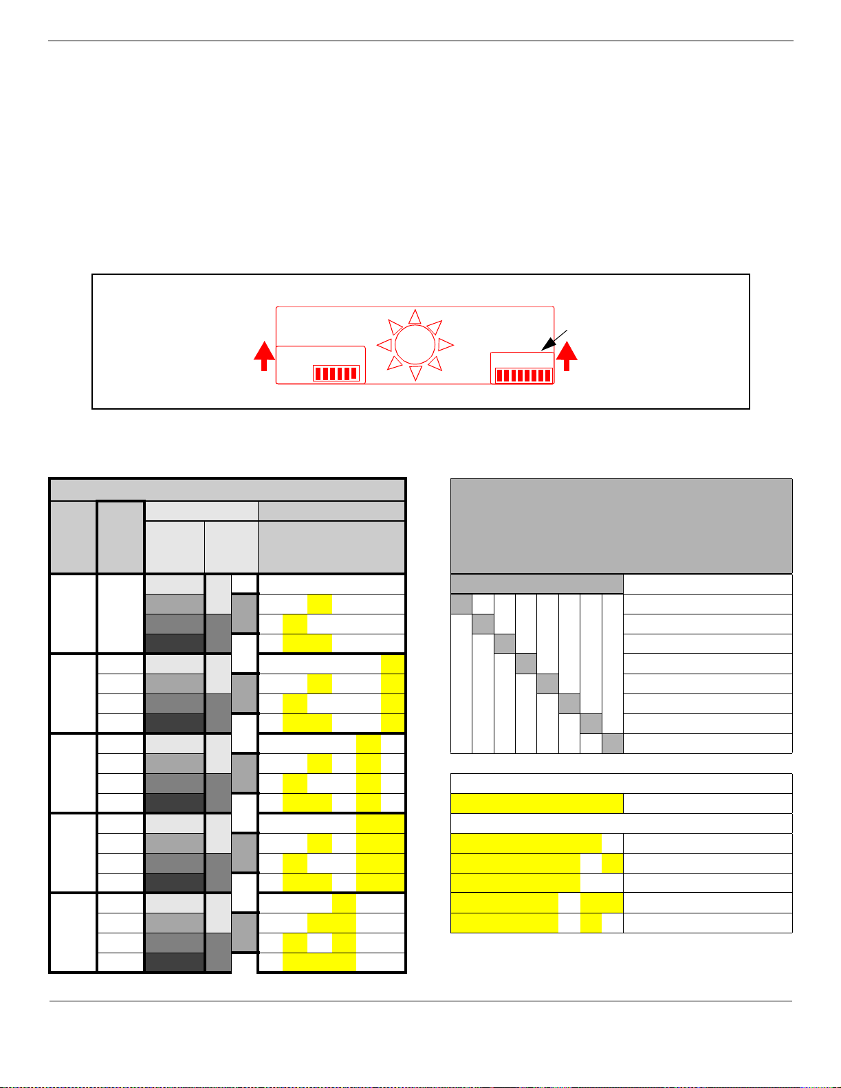
The figure below shows the front of the GATM module. Note that both the GA TM4 and the GATM8 have
only one amphenol connector. The firmware differentiates how many lines the connector supports.
Power LED
Status LED
Amphenol
connector
There are two models of GATM:
GATM 4: The GATM4 provides connections for four analog calling line identification (CLID) or
Supervision Disconnect PSTN lines. Each voice line uses one line in the DS30 bus offset. Since each
DS30 channel has four lines per offset, you can assign a maximu m of four GATM4s to a single DS30 bus
by making the offset switch settings different for each module.
GATM 8: The GATM 8 provides connections for eight analog calling line identification (CLID) or
Supervision Disconnect PSTN lines. Each line uses one line in the DS30 bus offset. Since each DS30 bus
has four lines per offset, you require two offsets for each GATM8. You can assign a maximum of two
GATM8s to a DS30 bus, by making the offset switch settings different for each module. You can also
combine a GATM 8 with a 4X16 module on the same DS30 number. When you choose an offset number
for the GATM 8, the system automatically adds the next offset number . You cannot assign offset 3 to the
GATM 8 module, because this does not allow the module to assign the second set of lines.
The following figure graphically shows how you can allocate the GATM modules over a DS30 bus.
One DS30 Bus/
offset 0, 1, 2, or 3
4 GATMs
per DS30
channel
One DS30 Bus/
offset set to 0, 1, or 2
GATM8s
max. of
2 offsets
per DS30
channel
(a maximum of
two GATM8s per bus)
Combined allocation
over one DS30 Bus
2 GATM4s
(offset 0 and 1)
1 GATM8
(offset 2)
Combined allocation with 4X16
using two DS30 buses
1 GATM8 (offset 0)
(offset 2 is empty)
1 4X16 module
(offset 3 on the
first DS30 bus)
P0607659 02 BCM1000 Installation and Maintenance Guide
Page 18
18 BCM1000, BCM 3.5 addendum
Rear of GA TM
GATM switch settings
There are two sets of DIP switches located on the rear of the GATM module. The left set allows you to
determine the DS30 bus and offset for the module.
The right set of switches allows you to manually configure a country profile operation, which is required
for earlier versions of software. However, BCM 3.5 software supports downloadable firmware for the
module for the North America, Taiwan, UK and Australia telephone profiles. To allow the GATM to
download the parameters for these countries and to allow for firmware upgrades, set all the country DIP
switches to 0 (zero/off) (factory default). The MSC telephony profile you choose must support the
appropriate country setting to ensure that the correct firmware installs.
For BCM 3.5 software,
ensure all switches
are off
ON
Mode select
The table below lists the possible DIP switch settings for the Mode and Country DIP switches.
Table 2 Global Analog Trunk Module DIP switch settings
Mode select DIP switch settings
DS30
bus #
Offsets Offset positions DIP switch settings
GATM4
Offsets
0, 1, 2, 3
0 0 0 on on on on on on
2
3
4
5
6
1 1 1 on on off on on on Reserved
2 2 2 on off on on on on Reserved
3 3 on off off on on on Reserved
0 0 0 on on on on on off Reserved
1 1 1 on on off on on off Reserved
2 2 2 on off on on on off Country 3
3 3 on off off on on off Country 2
0 0 0 on on on on off on Country 1
1 1 1 on on off on off on
2 2 2 on off on on off on Setting for automatic downloads (all countries)
3 3 on off off on off on off off off off off off off off Download based on profile
0 0 0 on on on on off off Manual settings (pre-BCM 3.5 systems)
1 1 1 on on off on off off off off off off off off off on North America (600 ohms)
2 2 2 on off on on off off off off off off off off on off Taiwan
3 3 on off off on off off off off off off off off on on Australia
0 0 0 on on on off on on off off off off off on off off United Kingdom
1 1 1 on on off off on on off off off off off on off on North America (900 ohms)
2 2 2 on off on off on on
3 3 on off off off on on
GATM8
Offsets
0, 1, 2
12 3
(offset)
1 2 3 4 5 6
45 6
(DS30 #)
1 2 3 4 5 6 7 8
ON
Country select
Country select DIP switch settings
12 3 456 7 8
Switch Function
BCM1000 Installation and Maintenance Guide P0607659 02
Page 19
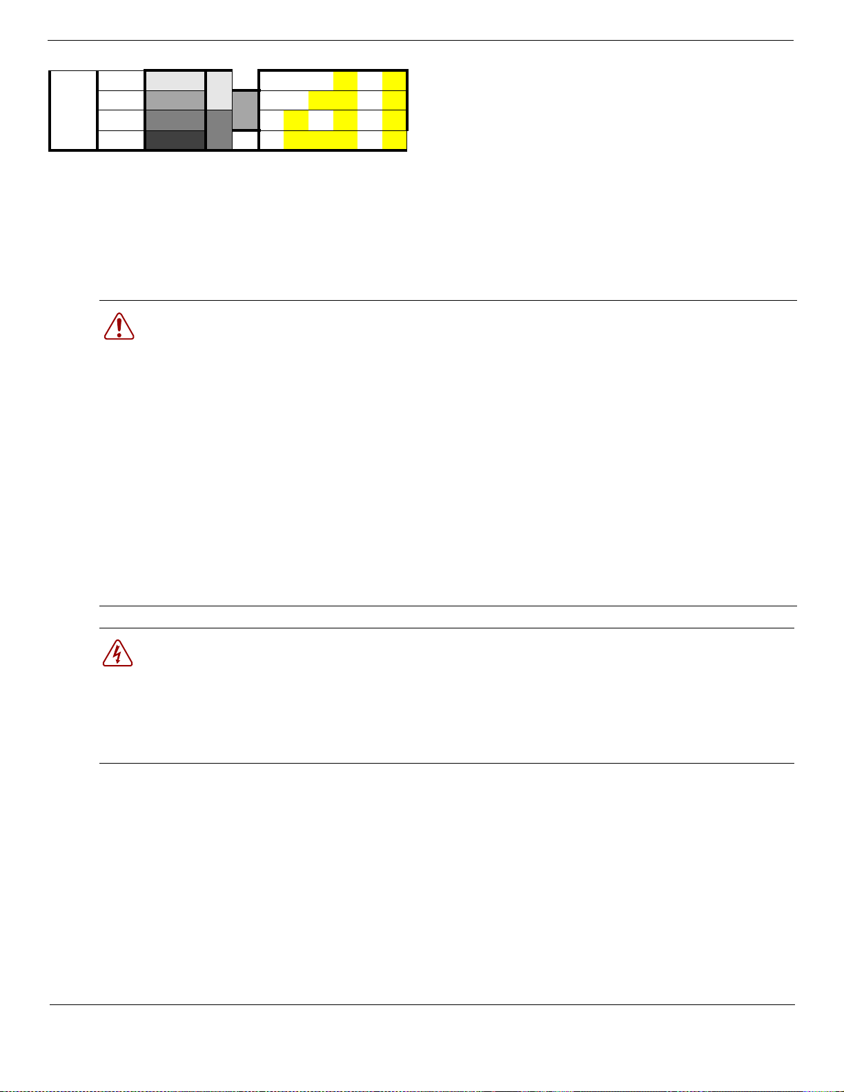
Table 2 Global Analog Trunk Module DIP switch settings
0 0 0 on on on off on off
7
1 1 1 on on off off on off
2 2 2 on off on off on off
3
3onoff off off on off
Wiring the GATM
The other trunk media bay modules are connected using RJ-type jacks. The GATM, however, uses an
amphenol connector. These cables can be supplied by qualified technical personnel to ensure the correct
pin-out.
War ning: Use only qualified persons to service the syst em.
The installation and service of this unit must be performed by service personnel with the appropriate
training and experience. Service personnel must be aware of the hazards of working with telephony
equipment and wiring. They must have experience in techniques that minimize any danger of shock or
equipment damage.
Warning: Leakage currents
Service personnel must be alert to the possibility of high leakage currents becoming available on metal
system surfaces during power line fault events on network lines. These leakage currents normally safely
flow to Protective Earth ground via the power cord. However, if the ac power is unplugged prior to
disconnecting the cables from the front of the base unit, this hazard can occur.
BCM1000, BCM 3.5 addendum 19
System shutdown: You must disconnect the media bay module cables from the system before
disconnecting the power cord from a grounded outlet.
System startup: You must reconnect the power cords to an grounded outlet before reconnecting the
cables to the media bay modules.
Danger: Electrical shock hazards
Electrical shock hazards from the telecommunications network and ac mains are possible with this
equipment. To minimize risk to service personnel and users, the Business Communications Manager
system must be connected to an outlet with a third wire ground.
In addition, all unused slots must have blank faceplates installed. The covers on all units must be in
place at the completion of any servicing.
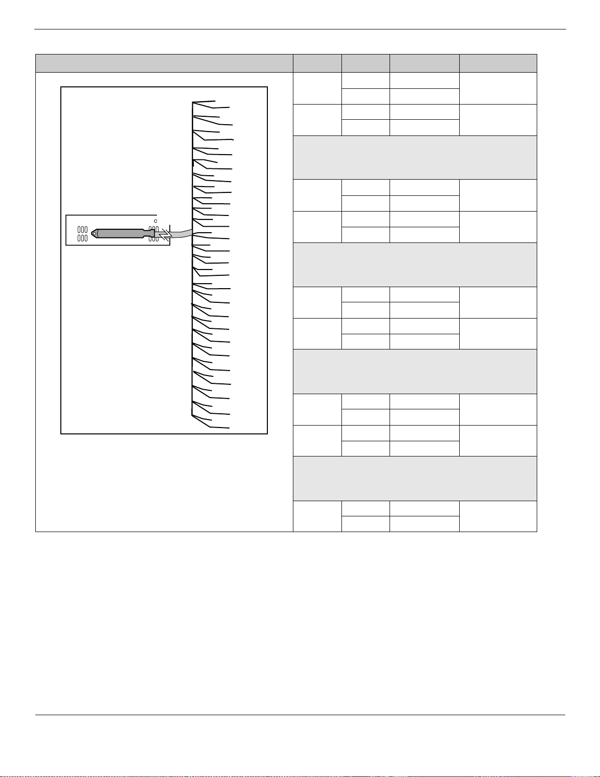
To connect the Global analog trunk module (GATM) to the network, follow these steps:
1. On the front of the module, locate the amphenol connector.
2 Wire one end of the cable to the telco demarcation blocks of the building.
3 Wire the other end of the cable to the analog lines. Refer to the figure and table on the next page.
P0607659 02 BCM1000 Installation and Maintenance Guide
Page 20
20 BCM1000, BCM 3.5 addendum
The following figure and table show the wiring pin outs for a GATM to connect to a service provider .
Connector pinout Line Pin Wire color GATM module
Line 1
Line 2
Line 3
Line 4
Line 5
Line 6
Line 7
Line 8
*AUX
6R
7R
8R
9R
10R
11R
12R
13R
14R
15R
16R
17R
18R
19R
20R
21R
22R
23R
24R
25R
1 R
2R
3R
4R
5R
26 T
27T
28T
29T
30T
31T
32T
33T
34T
35T
36T
37T
38T
39T
40T
41T
42T
43T
44T
45T
46T
47T
48T
49T
50T
1 26 White-Blue Both
1 Blue-White
2 27 White-Orange Both
2 Orange-White
No
connectio
28/3
29/4
n
3 30 White-Slate Both
5 Slate-White
4 31 Red-Blue Both
6 Blue-Red
No
connectio
32/7
33/8
n
5 34 Red-Brown GATM8
9Brown-Red
6 35 Red-Slate GATM8
10 Slate-Red
No
connectio
36/11
37/12
n
7 38 Black-Green GATM8
13 Green-Black
8 39 Black-Brown GATM8
14 Brown-Black
No
connectio
40/15 to
49/24
n
Aux 50 Violet-Slate Both
25 Slate-Violet
* Auxiliary port function: In download mode, the auxiliary port function for all profiles operates as a true Auxiliary
port. This means that when the power comes back on, and if the Aux Port is in-use, that line will show on the
system telephones as being in-use (LCD indicator lit) until the Aux Call is cleared.
In dipswitch mode, the North American and Taiwan auxiliary ports also act as true auxiliary ports.
However, the UK and Australia profile auxiliary port function is different. In these profiles, when the power is
restored, the Aux Port call is terminated and the line is available to system telephones.
BCM1000 Installation and Maintenance Guide P0607659 02
Page 21
Auxiliary equipment
The BCM 3.5 software release also introduces support for some auxiliary equipment:
• A new telephone and add-on module are being introduced to replace the M7324/CAP module as a Central
Answering Position ( CAP). A T7316E tele phone conne cted to one or more Key In dicator Module s (KIMs) is still
referred to as a CAP. When it becomes an enhanced CAP (eCAP), the KIMs support line appearances, multip le
appearances of the same target line, and hunt group appearances. Ref er to
and KIMs below.
• The BST Doorphone is installe d outside exterior doors. The device provides ringing at one or more system
telephones and/or an ale rting tone through the paging feature.
Verbal communication can be initiated to the doorphone by dialing the doorphone DN from any system
telephone. Communication can be initiated from the doorphone by pressi ng the Call button to create a ring or an
alert at the assigned internal telephone. The voic e path is c reated when the user at the internal telephone answers
the call, either by picking up the handset or pressing the Handsfree butt on.
With the addition of Door Ope ning Controll er ( DOC) hardware, the user can also open the door usin g a telephon e
display key or r elease digi t on th e telephon e dial pad. Refe r to the BST Doorphon e Inst allation and Conf iguration
Guide for details about conf iguring the system and installing the hardware .
• This release of fi rmware also introduces support for a Univer sal Power Supply (UPS). This third-party hardware
provides short-term power backup in case of a main power failure on your Business Communications Manager.
The UPS has separate installation and configuration documentation specific to Business Communications
applications. Also, the unit comes with manufacturer instructions.
BCM1000, BCM 3.5 addendum 21
T7316E Business Series Terminal
T7316E Business Series Terminal and KIMs
The T7316E BST telephone has a two-line display, three display keys, 16 memory keys with indicators,
eight memory buttons without indicators. This telephone has handsfree ability, accessed from a button
located under the dial pad. Also under the dial pad are a mute button that mutes for all features, and a
headset button which allows the user to attach a headset and direct the call to the headset or the handset
without needing to disconnect the headset. In progr amming, the handsfree feature must be set to Auto for
these features to work correctly.
T7316E
Mute
Handsfree
Headset
On this telephone model, the current incoming call on this telephone defaults to the voice path last used.
For example, if you answered the previous call using your headset, the next call will come in over your
headset.
P0607659 02 BCM1000 Installation and Maintenance Guide
Page 22

22 BCM1000, BCM 3.5 addendum
The T7316E can be used alone or you can expand feature and line button capacity by adding one or more
Key Indicator Modules (KIMs). Each KIM has 24 buttons with indicator displays. A combination of
T7316E+KIMs is still referred to as a Central Answering Position (CAP).
A KIM connected to a T7316E that is configured under CAP/KIM assignment as an enhanced CAP
(eCAP) supports line appearances, multiple appearances of a target line and/or hunt group appearances.
In this configuration, the KIM is referred to as an eKIM. A T7316E supports a maximum of four eKIMs.
The Business Communications Manager can support a maximum of 12 eCAPs.
T7316E with KIM
A T7316E+KIM that is not configured in system programming does not support line appearances, target
line appearances, or hunt group appearances. For this configuration, the KIM is referred to as an OKIM.
A T7316E can support a maximum of nine OKIMs. You need to add a system auxiliary power supply
(SAPS) if you install five or more OKIMs on a T7316E. The system can support as many
T7316E+OKIM combinations as required.
You can configure the KIM buttons for features and autodial numbers under User Pref erences,
CAP/KIM button p r ogramming. The user can also configure memory button features at the telephone.
The user can move lines from the T7316E to an eKIM, or from eKIM to eKIM, but initial line assignment
and hunt group appearance assignment occurs in system programming.
The T7316E telephone displays a set of icons in place of flashing arrows when it is connected to a
system with BCM 3.5 software. If you connect a T7316E telephone to a system that is running previous
versions, the standard line indicators display. The KIM also displays these icons. KIMs are only
supported by BCM 3.5 and later software.
Table 3 T7316E and KIM display icons
Active call The line is active and/or you are connected to this telephone.
,
Ringing A call is coming into this line.
Hold The call on this line is on Hold at this telephone.
Call forward The call on this line has been forwarded.
Active button The feature assigned to this button is active. Also used by Do Not Disturb.
Refer to the Business Communications Manager 3.5 Programming Operations Guide for details about
programming the T7316E and CAPs.
BCM1000 Installation and Maintenance Guide P0607659 02
Page 23

The KIM hardware and T7316E both come with installation and initial setup user cards. Refer to the CAP
User Card for details about using the T7316E+KIM as part of your telephony system.
Market profile changes
A new market profile for Brazil is available in BCM 3.5 software.
The following table shows the core software available to each region.
Table 4 Core software, defined by region and carrier profile
Core Software
(Carrier s/w ID) T1 CT2 Plus
BCM1000, BCM 3.5 addendum 23
T1 Etiquette E1 Euro E1 Global E1 CALA
Region
South American and Central American countries are assigned to regions in the following way:
• Caribbean includes Antigua, Bahamas, Barbados, Bermuda, Cayman Islands, Dominican Republic, Jamaica,
USVI, Puerto Rico, and Trinidad
• CALA refers to all other Caribbean and Latin American countries with European-based standards.
Brazil
Caribbean
Hong Kong
North
American
Taiwan
Caribbean
Hong Kong
North
American
Taiwan
Denmark
France
Germany
Holland
Italy
Norway
Spain
Sweden
Switzerland
United Kingdom
The following table lists the languages available for each telephony region and the order in which the
languages are set as default.
Table 5 Telephony region Languages
Region Language Region Language
CALA
Caribbean
Hong Kong
North American
PRC
Taiwan
NA English, NA French, NA Spanish France Euro French, NA English
Germany German, NA English
Global NA English, NA French, NA Spanish,
Turkish
Holland Dutch, Euro French, NA English
Italy Italian, NA English
Norway Norwegian, Swedish, Danish, NA English
Australia
CALA
Global
PRC
Australia
CALA
Global
PRC
Australia
United
Kingdom
Brazil Portuguese Switzerland German, Euro French, Italian, NA English
Denmark Danish, Norwegian, Swedish, NA
P0607659 02 BCM1000 Installation and Maintenance Guide
UK English
English
Spain Euro Spanish, NA English, Portuguese
Sweden Swedish, Norwegian, Danish, NA English
France Euro French, NA English
Page 24

24 BCM1000, BCM 3.5 addendum
CallPilot profiles: The following table lists the default prime language for the countries (regions) where
the voice mail application is supported.
Table 6 CallPilot region default voice mail languages by country
Country Default language Country Default language
North America
Australia
Caribbean
Global
Hong Kong
UK
Europe
Denmark Danish
Holland Dutch
Sweden Swedish
NA English
UK English
The following table shows the companding law used for each region.
Table 7 Companding laws and profiles
Companding Law
mu-law
Caribbean
Hong Kong
North American
Taiwan
A-law
Australia
Brazil
CALA
Denmark
France
Germany
Global
Holland
Italy
Norway
PRC
Spain
Sweden
Switzerland
United Kingdom
France Euro French
Germany
Switzerland
CALA LA Spanish
Italy Italian
Norway Norwegian
Spain Spanish
PRC
Taiwan
Brazil Portuguese
German
Mandarin (Taiwan)
BCM1000 Installation and Maintenance Guide P0607659 02
Page 25

BCM1000, BCM 3.5 addendum 25
The following table shows the Mobility se rvic es that are supported by the Busine ss Communicati ons Manager, and
the regions that can use each type.
Table 8 Mobility services, by region
Available
Mobility service
Region
Companion
(CT2-Plus, Etiquette)
Caribbean
Hong Kong
North American
PRC
Compani o n (CT2-Pl u s )
CALA
Brazil
Companion (CT2-Plus,
Etiquette), DECT
DECT
Taiwan Australia
Denmark
France
Germany
Global
Holland
Italy
Norway
Spain
Sweden
Switzerland
United Kingdom
Some of the media bay modules are customized for a specific type of line and are not available to all
regions. The following table lists a cross-reference between regions and modules.
Table 9 Module availability, by profile
Region DSM ASM CTM 4X16 GATM BRI DTM DECT
Australia X X XXX
Brazil X X X X X
Caribbean XXX XX
CALA X X X X X
Denmark X XXX
France X X X X
Germany X XXX
Global X X X X X X
Holland X XXX
Hong Kong X X X X X X
Italy X XXX
North American X X X X X X X
Norway X XXX
PRC X X X X X
Spain X XXX
Sweden X X X X
Switzerland X XXX
Taiwan X X X X X X X
United Kingdom X X XXX
P0607659 02 BCM1000 Installation and Maintenance Guide
Page 26

26 BCM1000, BCM 3.5 addendum
Table 10 PRI line protocol supported, by region
Region BRI T side BRI S side PRI T1
Australia ISDN ETSI 300
403
Brazil
CALA
Caribbean
North American
Hong Kong
Taiwan
Denmark
France
Germany
Global
Holland
Norway
PRC
Spain
Sweden
Switzerland
Italy ISDN ETSI 300
United Kingdom ETSI QSIG 300
ISDN ETSI 300
403, ETSI QSIG
300 239
NI-2 NI-2 NI-2
ITU-T ITU-T ITU-T Loop
ETSI QSIG 300
239, ISDN ETSI
300 403
102 ETSI QSIG
300 239
239, ISDN ETSI
300 403
ISDN ETSI 300 102 DASS2
DPNSS
MCDN
ISDN ETSI 300 403,
ETSI QSIG 300 239,
ISDN ETSI 300 102 ETSI QSIG 300 239,
ISDN ETSI 300 403,
MCDN
4ESS
DMS100
DMS250
MCDN
ISDN ETSI 300 102 DASS2
DPNSS
MCDN
ETSI QSIG 300 239
ISDN ETSI 300 403
ISDN ETSI 300 102 DASS2
DPNSS
MCDN
ETSI QSIG 300 239
ISDN ETSI 300 102
ISDN ETSI 300 102 DASS2
DPNSS
MCDN
ETSI QSIG 300 239
ISDN ETSI 300 403
Loop
E&M
DID
Ground
Fixed trunk types
E&M
DID
Ground
Fixed trunk types
Product and documentation updates
For the latest information about Business Communications Manager product and documentation updates, access
the Nortel Networks web site at the following URL:
http://www.nortelnetworks.com/support
BCM1000 Installation and Maintenance Guide P0607659 02
Page 27

Business Commu nications Manager 3.0.1
functional changes for BCM1000
BCM 3.0.1 program updates
This document provides supplemental information about release 3.0 for systems using
BCM1000s that has been upgraded from Business Communications Manager, software
version 3.0 to version 3.0.1 (maintenance release).
Initializing the hard disk (single-disk system)
The BCM1000 is normally initiali zed at the factory. However, if you have to replace the hard
drive in a single-disk BCM1000 running BCM versi on 3.0.1 (3.0 maintenance release), you
must re-initializ e the Business Communications Manager.
After you replace the hard disk and the system has booted up, perform the initialization as
follows:
1. Ensure the Status LED on the Business Communications Manager is lit. The
Status LED indicates that all services have started and the Business
Communications Manager is operating correctly.
2 Attach a configuration computer to the base function tray serial port
(recommended method). Continue to the next step in this procedure when
complete.
Note: When you replace a hard disk, IP configuration data is lost. The
Business Communications Manager IP address defaults to: 10.10.10.1
You can access the Business Communications Manager through your local area
network, using the IP address 10.10.10.1. However, if another network
terminal uses this IP address, conflicts and network problems can arise.
3 Access the Business Communications Manager from the configuration terminal
using the terminal emulation program. Use the Business Communications
Manager default IP address (10.10.10.1).
4 Enter the terminal emulation program, as described in Finding the configuration
menus on page 170. The Main Menu should display (Figure 1).
Functional changes, 3.0.1 software
Page 28
28 BCM1000, BCM 3.0.1 addendum
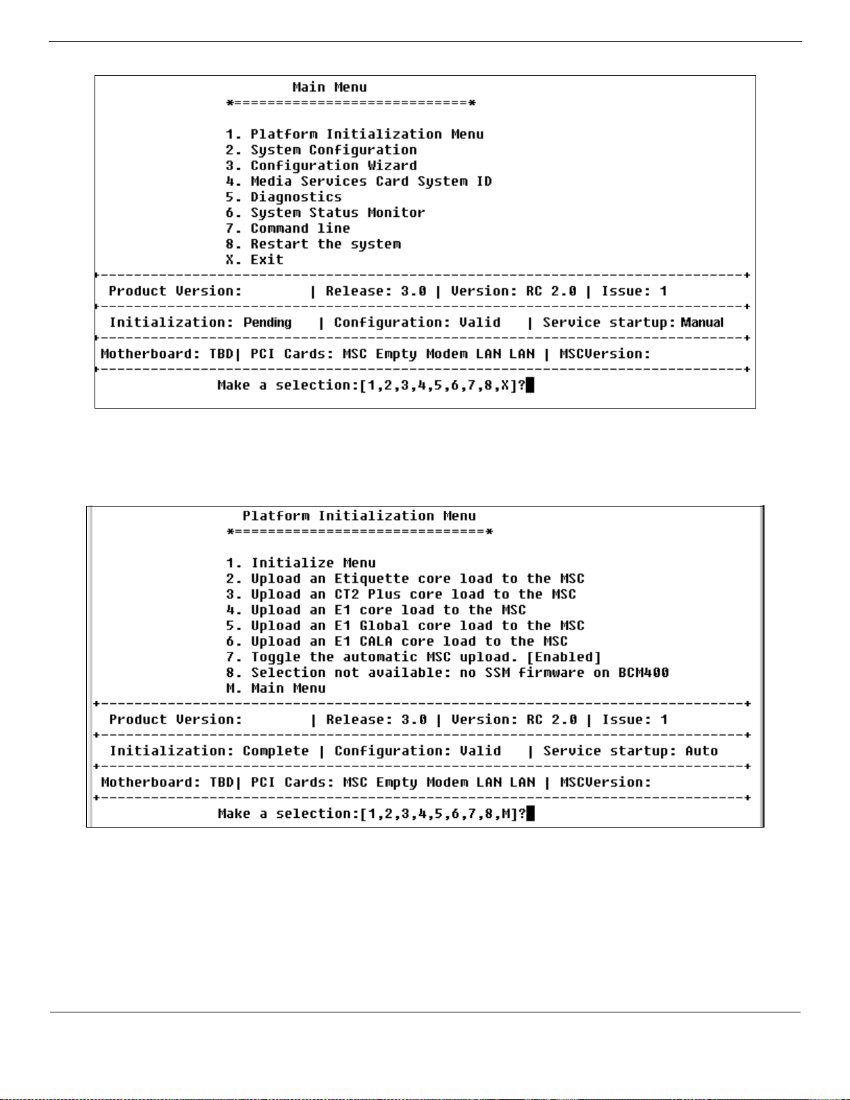
Figure 1 Main Menu screen
BCM1000
5. Select1 (Platform Initialization Menu) and press <ENTER>.
The screen shown in Figure 2 appears.
Figure 2 Platform Initialization Menu screen
BCM1000
6. Select 1 (Initialize Menu) and press <ENTER>.
The Initialize Menu appears. Refer to Figure 3.
BCM1000 Installation and Maintenance Guide P0607659 02
Page 29
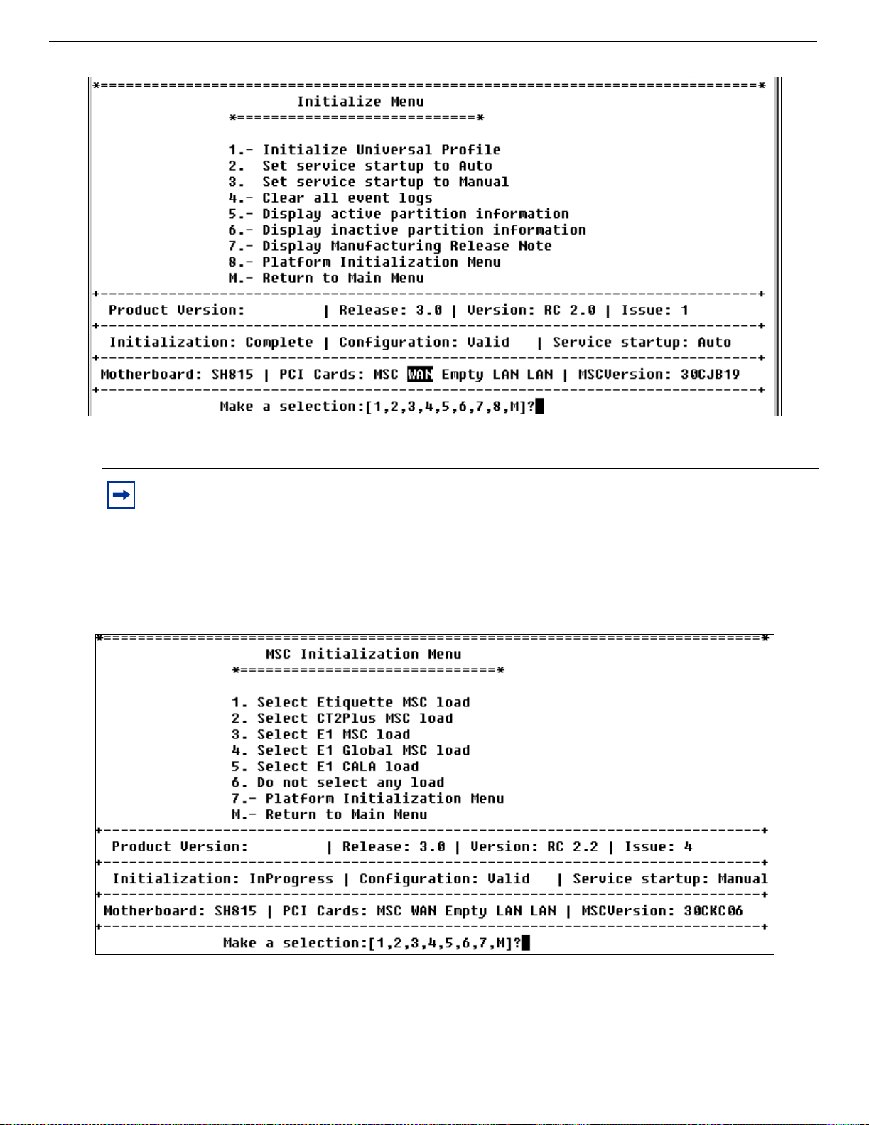
Figure 3 Initialization Menu screen
BCM1000
BCM1000, BCM 3.0.1 addendum 29
7. Select 1 (Initialize Universal Profile) and press <ENTER>.
Note: If the initialization process detects a core s oftware loa d mismatch be tween the MSC and the
hard disk, the system displays a menu screen that prompts you to enter the most appropriate core
load (Figure 4). The load on the MSC is the most recent load (if you replaced the hard disk).
Select menu option 6 “Do not select any load” to by-pass the core upload and continue with the
initialization process.
Figure 4 MSC Initialization Menu screen
BCM1000
P0607659 02 BCM1000 Installation and Maintenance Guide
Page 30

30 BCM1000, BCM 3.0.1 addendum
Note: The initialization process is automatic and takes approximately 40 minutes. The system
automatically reboots a number of times as part of the initialization process. When the first
reboot occurs, the telnet session disconnects.
8. When the initialization process is complete, restart a telnet session with the Business
Communications Manager.
9 At the main menu, select 2 (System configuration) and press <ENTER>.
The System Configuration login prompt appears.
10 Enter the default login UserID and password.
The System Configuration Start Page screen appears (see Figure 5).
Figure 5 System configuration start page
11 Enter q (Quick Start Page 1) and press <ENTER>.
The Quick Start Page screen appears (Figure 6)
BCM1000 Installation and Maintenance Guide P0607659 02
Page 31

BCM1000, BCM 3.0.1 addendum 31
Figure 6 Quick start page
12 Enter the correct informatio n fo r LAN1 (a), LAN2 (i), Subnet masks (m and j), Default next hop
router (r ) and Sys tem name (s ) , as required. Enter p after each change to apply it.
13 Enter b (go back) to return to the System Configuration Start Page screen after all network IP
addresses are configured.
14 Enter r to reboot the system and to apply the network IP address changes
15. Do one of the following:
• Run the Quick Start Wizard and manually reconfigure your system.
• Run the Quick Start Wizard to create the system parameters and defaults. Then restore your system
data from your backup disk.
• Restore system and data information from your backup disk.
War ning: You can only perform a restore from a current backup disk that was backed up from the
same software version as your system is currently running. In this case, if you do not have a backup
that was run on a version 3.0.1, you need to manually reenter your data.
16 Test your system for correct operations.
P0607659 02 BCM1000 Installation and Maintenance Guide
Page 32

32 BCM1000, BCM 3.0.1 addendum
Product and documentation updates
For the latest information about Business Communications Manager product and documentation updates, access
the Nortel Networks web site at the following URL:
http://www.nortelnetworks.com/support
BCM1000 Installation and Maintenance Guide P0607659 02
Page 33

Business Communications Manager 3.0
functional changes for BCM1000
BCM 3.0 program updates
This document provides supplemental information about release 3.0 for systems using
BCM1000s that has been upgraded from BCM 2.5 software.
This information includes:
• Platform compatibility
• Explaining Double Density
• Setting module DIP switches for double density on page 35
• Upgrading from a standard system on page 39
• Initializing the hard disk (single-disk system) on page 40
Platform compatibility
Business Communications Manager 3.0 is Windows XP compatible, therefore, any references
in the main document about required computer platforms can include computers running
Windows XP.
Explaining Double Density
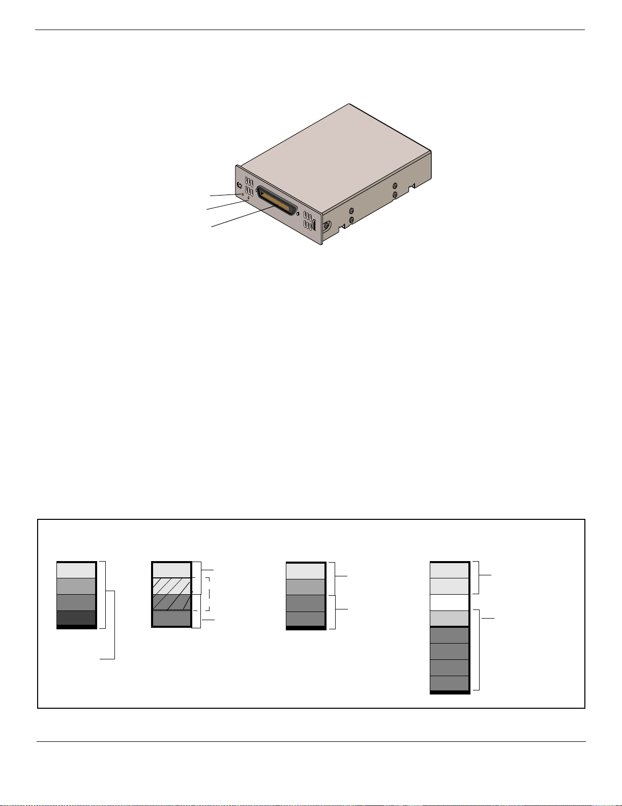
Business Communications Manager 3.0 soft ware now utilizes the B2 channels on DS30 buses
02 to 07 for digital telephones, thereby, doubling telephone capacity. The following figure
shows a DS30 bus broken down into four offset groups of four (single density) or eight (double
density) lines each.
Figure 11 Offsets are part of DS30 bus line groups
Offsets
have
four lines (single density)
8 lines (double density)
The default 3.0 system is a Partial Double Density (PDD) system, in that it maintains DS30 06
and 07 in the original configuration of 16 lines per bus. This accommodates those systems
which use Companion. If you choose to set your system to Full Double Density (FDD),
DS30 06 and 07 become FDD and are no longer available for Companion operation.
To take advantage of the double density functionality, you require DSM16+ or DSM32+
modules. The existing ASM8 modules can also utilize FDD.
Offset 0
Offset 1
Offset 2
Offset 3
1 DS30 bus
16 lines/32 time slots (single density)
32 lines/32 time slots (double density)
Functional changes, 3.0 software
Note: Devices that share a DS30 channel must be identical. Use two DSM 16+ modules in
full double density mode on a single DS30 channel. Likewise , use two DSM 32+ modules
in full double density mode on a single DS30 channel.
Page 34

34 BCM1000, BCM 3.0 addendum
Full double density means that instead of a DSM16 module occupying a full DS30 bus, the DSM16+ can be set
to double density, so that it occupies only half the bus, allowing you to install a second DSM16+ set to double
density with offset 1. This doubles the available telephone lines from 16 to 32. Similarly, where the DSM 32
required two DS30s, if the DSM32+ is set to double density, the module only requires one DS30 bus to support
all 32 lines. The ASM8 requires no special settings to take advantage of double density. You can simply install
four modules on one DS30 bus, with the dip switches set to the four offsets. The exception is for DS30 06 and 07
if they are set to PDD. In that instance, you can still only install two ASM8s per bus.
Figure 12 shows how much of a DS30 bus each station module requires.
Figure 12 Space requirements for station media bay modules, on a per-DS30 configuration
2 DS30 buses/
offset set to 0
Single-density mode
1 DS30 bus/
offset set to 0
1 DSM 32
per 2 DS30s
PDD note: If DS30 6 and 7 are in
partial double density mode, you can
only install modules set to single
density. This also means that only two
ASM8s could be installed on each
DS30 bus.
1 DSM 16
per DS30
1 DS30 bus
Double-density mode
1 DS30 bus
2 DD
DSM 16+
per DS30
1 DS30 bus/
4 DD ASM8s
per DS30
1 DD
DSM 32+
per DS30
The following diagram provides a system view of what double density looks like from a system perspective. Note
that this example is based on the default setting, which provides partial double density to DS30 06 and 07.
Installation and Maintenance Guide P0607659 02
Page 35

Figure 13 Assigning double density modules to the DS30 bus hierarchy
BCM1000, BCM 3.0 addendum 35
Example of
Double-density example
North Americanbased setup
(system configured as PDD)
Partial density
Systems configured with Partial double density (PDD), allow
Companion telephones on DS30 06 and 07 (if the system is
set to a 2/6 split). In this configuration, DS30 06 and 07 only
allow single-density modules. DS30 02 to 05 are set to allow
double density modules.
Double density
Systems configured with Full double density (FDD), do not
allow Companion telephones. All DS30s are set to allow
double density modules.
3/5 channel split
If your system is set to a 3/5 split, DS30 07 is not available to
any media bay modules.
DD DSM 32+
DD DSM 16+
DD DSM 16+
CTM
CTM
CTM
4X16
DS30 5 supports
the station module
part of the 4X16
SD DSM 32
DS30
buses
02
03
04
05
06
Example of a
European- based
setup
DD DSM 32+
DD DSM 32+
DD DSM 32+
BRI
BRI
Companion
DECT
07*
Setting module DIP sw itches for double dens ity
Doubling the available telephone lines also requires additional DN records to accommodate the additional
telephones. The following charts show the DIP switch settings for single and double-density. Note that the ASM8s
do not have special double-density/single-density settings, whereas DSM16 and DSM32 modules must be set to
one mode or the other.
Note that the second set of 16 lines are not consecutively numbered from the first set. This was done to
accommodate existing installations.
ASM 8 switch settings
In a single density configuration, such as for DS30 06 or 07 when they are set to the default PDD, only offset 1
and 2 are available to ASM8s. In a double-density configuration, you can install four ASM8s per DS30 bus. Table
1 shows the switch settings for each DS30 bus and the dialing numbers (DNs) assigned to each DS30.
P0607659 02 Installation and Maintenance Guide
Page 36

36 BCM1000, BCM 3.0 addendum
Table 1 ASM8 settings for 2.5 systems upgraded to 3.0 software
Select
1
2
3
4
Select
bus
offset
2.5 system upgraded to 3.0 2.5 system upgraded to 3.0
0
02
03
04
1
2
3
0
1
2
3
0
1
2
3
Enter these switch
settings
123456 123456
on on on on on on 221-228
on on offononon228-236
on offonononon377-384
on off offononon385-392
on on on on on off 237-244
on on off on on off 245-252
on offonononoff 393-400
on off off on on off 401-408
on on on on off on 253-260
on on off on off on 261-268
on off on on off on 409-416
on off off on off on 417-424
T o assign
these
1
DNs
Select
bus
05
06
2
07
Select
offset
0
1
2
3
0
1
3
2
3
3
0
1
4
2
4
3
Enter these switch
settings
on on on on off on 269-276
on on off on off on 277-284
on off on on off on 425-432
on off off on off on 433-440
on on on on off off 285-292
on on off on off off 293-300
on off on on off off 441-448
on off off on off off 449-456
on on on off on on 381-388
on on off off on on 389-396
on off on off on on 457-464
on off off off on on 465-472
To
assign
these
DNs
The extensions listed are based on a three-digit DN with a Start DN of 221. If your system has longer DNs or a different
Start DN, enter the range in the blank column.
If your system is configured with a 3/5 channel split, DS30 07 is not available.
Available only on systems set to FDD.
Available only on systems set to FDD, with a 2/6 DS30 split.
1
Custom DN
range
DSM16/DSM 32 single density switch settings (upgraded system)
The following table shows the switch settings for DSM modules deployed as single density on a system that has
been upgraded from Business Communications Manager version 2.5 to version 3.0. All your current modules are
probably single-d ensity modules. If you intend to continue to use them, you do not have to change any settings.
They will continue to function in the same manner as before.
DSM16+ and DSM32+ modules can be set to either density. To set them for single density, refer to the following
table. To set them to double density, refer to the table under
DSM16+ and DSM 32+ double density switch
settings (upgraded system) on page 37.
Note that Companion sets can only be assign ed on DS30 06 and 07, which have single-density DSM modules.
Companion handsets have a different set of default DNs than the digital sets. Also, Companion can only be
deployed on systems that remain at Part Double Density (PDD), the default condition of 3. 0 systems.
Table 2 DSM 16/DSM 16+ and DSM 32/DSM32+ single density switch settings for 2.5 systems upgraded to 3.0
1
Select
DS30
bus
Enter these switch
settings
1 2 3 456
02 on on on on on on 221-236 221-252 (DS30 02 and 03)
03 on on on on on off 237-252 237-268 (DS30 03 and 04)
04 on on on on off on 253-268 253-284) (DS30 04 and 05)
05 on on on on off off 269-284 269-300 (DS30 05 and 06)
06 on on on off on on 285-300 285-316 (DS30 06 and 07)
2
07 on on on off on off 301-316 N/A
To assign
these DNs
to
DSM16 or
DSM 16+
To assign these DNs to DSM 32 or
DSM 32+
4
To assign these DNs
to Companion
N/A
3
565-580 (PDD only)
3
581-596 (PDD only)
Installation and Maintenance Guide P0607659 02
Page 37

BCM1000, BCM 3.0 addendum 37
Table 2 DSM 16/DSM 16+ and DSM 32/DSM32+ single density switch settings for 2.5 systems upgraded to 3.0
1
The extensions listed are based on a three-digit DN with a Start DN of 221. If your system has longer DNs or a different
Start DN, enter the range in the blank column.
2
If your system is configured with a 3/5 DS30 split, you cannot use DS30 07 for the DSM 16 module. You cannot
configure the DSM32 module for DS30 06 because the second set of DNs cannot be accessed.
3
If you need more DNs for Companion sets, use the range that starts at 597 (ISDN or DECT) and change the
DN type to NA Portable.
4
If you system is set to Full Double Density (FDD), Companion telephones are not supported.
DSM16+ and DSM 32+ double density switch settings (upgraded system)
The following table shows the switch settings for DSM-plus modules deployed as double density on a system that
has been upgraded from 2.5 to 3.0.
Note: DSM modules deployed with 2.5 sys tems are all single density and cannot be set to double density.
The DSM 16+ and DSM32+ modules can be set to either density.
Table 3 DSM 16+ and DSM32+ double density switch settings for 2.5 systems upgraded to 3.0
Select
DS30
bus
02
03
04
05
06
***07
Enter these switch settings
123456
offonononononA 221-236 A 377-392
off on off on on on B 377-392 B 221-236
offononononoff A 237-252 A 393-408
off on off on on off B 393-408 B 237-252
offonononoff on A 253-268 A 409-424
off on off on off on B 409-424 B 253-268
offonononoff off A 269-284 A 425-440
off on off on off off B 425-440 B 269-284
off on on off on on A 285-300 A 441-456****
off on off off on on B 441-456**** B 285-300
off on on off on off A 301-316 A 457-472*****
off on off off on off B 457-472***** B 301-316*****
**To assign these DNs to DSM
16+:
(A= DSM1, B=DSM2)
To assign these DNs to DSM 32+
(connectors: A=top,
B = bottom)
**The extensions listed are based on a three-digit DN with a Start DN of 221. If your system has longer DNs or a different
Start DN, enter the range in the blank column.
***If your system is configured with a 3/5 split, you cannot use DS30 07 for the DSM 16 module.
****Available only on systems set to FDD. Modules cannot be set to double density on systems set to PDD. Refer to the
previous chart for the switch settings for single density and PDD.
*****Available only on systems set to FDD, with a 2/6 DS30 split. Modules cannot be set to double density on systems set
to PDD. Refer to the previous chart for the switch settings for single density and PDD.
P0607659 02 Installation and Maintenance Guide
Page 38

38 BCM1000, BCM 3.0 addendum
CTM, CTM8 and 4X16 (CTM/DSM) switch settings
Select
bus
2 0
3 0
4 0
5 0
6 0
7 0
Select
offset
1
2
3
1
2
3
1
2
3
1
2
3
1
2
3
1
2
3
Enter these switch
settings
123456 Lower (Lines 1-4)/
T o assign
these
lines to a
CTM
T o assign these
lines
to a CTM8
Upper (lines 5-8)
T o assign
these
lines to a
4X16
CTM
portion
on on on on on on 211-214 211-214 / 219-222 211-214
on on off on on on 219-222 219-222 / 227-230 219-222
on offonononon 227-230 227-230 / 235-238 227-230
on off off on on on 235-238 N/A N/A 235-238
on on on on on off 181-184 181-184 / 189-192 181-184
on on off on on off 189-192 189-192 / 197-200 189-192
on offonononoff 197-200 197-200 / 205-208 197-200
on off off on on off 205-208 N/A N/A 205-208
on on on on off on 151-154 151-154 / 159-162 151-154
on on off on off on 159-162 159-162 / 167-170 159-162
on off on on off on 167-170 167-170 / 175-178 167-170
on off off on off on 175-178 N/A N/A 175-178
on on on on off off 121-124 121-124 / 129-132 121-124
on on off on off off 129-132 129-132 / 137-140 129-132
on off on on off off 137-140 137-140 / 145-148 137-140
on off off on off off 145-148 N/A N/A 145-148
on on on off on on 91-94 91-94 / 99-102 91-94
on on off off on on 99-102 99-102 / 107-110 99-102
on off on off on on 107-110 107-110 / 115-118 107-110
on off off off on on 115-118 N/A N/A 115-118
on on on off on off 61-64 61-64 / 69-72
on on off off on off 69-72 69-72 / 77-80
on off on off on off 77-80 77-80 / 85-88
on off off off on off 85-88 N/A N/A
And this DS30
channel and
DNs
DSM portion
CH 3
upgraded 2.5:
237-252
CH 4
upgraded 2.5:
253-268
CH 5
upgraded 2.5:
269-284
CH 6
upgraded 2.5:
285-300
CH 7
upgraded 2.5:
301-316
N/A
Custom
DN range
for 4X16
1 The extensions listed are based on a three-digit DN with a Start DN of 221. If your system has longer DNs or a
different Start DN, enter the range in the blank column.
1
Installation and Maintenance Guide P0607659 02
Page 39

Upgrading from a standard system
When you upgrade your BCM1000 from a single power supp ly and fan to a redundant system, you need to remove
the jumper from the connectors on the System Status Monitor board to allow the cables from the redundant
equipment to be connected.
The diagram below notes the locati on of the connec tors for the redundant power supply and for the redun dant fan.
Figure 7 System Status Monitor internal connectors
BCM1000, BCM 3.0 addendum 39
Mother board
Redundant power supply
monitoring cable
Redundant/primary fans
J6
J7
Mother board (J10)
Board power
CPU fan
Remote temperature
sensor
SSM board
Note: Chassis has all PCI
cards removed, for clarity
P0607659 02 Installation and Maintenance Guide
Page 40

40 BCM1000, BCM 3.0 addendum
Initializing the hard disk (single-disk system)
The BCM1000 is norm ally initialized at the factory. However, if you h ave to replace t he hard drive in a single-disk
BCM1000, you must re-initialize the Business Communications Manager.
After you replace the hard disk and the system has booted up, perform the initialization as follows:
1. Enter the terminal emulation program, as described in Finding the configuration menus on page 170.
The Platform Initialization Menu appears. Refer to Figure 8.
Figure 8 Platform Initialization Menu screen
2. Enter 1 (Initialize Menu) and press <ENTER>.
The Initialize Menu appears. Refer to Figure 9.
1-800-4 NORTEL
www.nortelnetworks.com
Installation and Maintenance Guide P0607659 02
P0993298 02
Page 41

Figure 9 Platform Initialization Menu screen
BCM1000, BCM 3.0 addendum 41
3. Enter 1 (Initialize Universal Profile) and press <ENTER>.
The MSC Initialization menu screen appears after about a minute. Refer to Figure 10.
Figure 10 MSC Initialization Menu screen
4. Enter the number beside the upload for the software you want to install. If you do not know which
software to upload, refer to Core software and regions on page 295.
5. The system automatically reboots as part of the initialization process. When the system reboots, the
telnet session disconnects.
Note: If there is a modem, the system reboots four times. If there is no modem, the system only reboots
twice.
P0607659 02 Installation and Maintenance Guide
Page 42

42 BCM1000, BCM 3.0 addendum
6. Do one of the following:
• Run the Quick Start Wizard to create the system parameters and defaults. Then restore your system data
from your backup disk.
• Res tore system and data information from your backup dis k.
17 Test your system for correct operations.
Product and documentation updates
For the latest information about Business Communications Manager product and documentation updates, access
the Nortel Networks web site at the following URL:
http://www.nortelnetworks.com/support
Installation and Maintenance Guide P0607659 02
Page 43

Contents
North American Regulatory Information . . . . . . . . . . . . . . . . . . . . . . . . . . . . 3
Safety . . . . . . . . . . . . . . . . . . . . . . . . . . . . . . . . . . . . . . . . . . . . . . . . . . . . . . . . . . . . . . . 3
Enhanced 911 Configuration . . . . . . . . . . . . . . . . . . . . . . . . . . . . . . . . . . . . . . . . . . . . 4
Radio-frequency Interference . . . . . . . . . . . . . . . . . . . . . . . . . . . . . . . . . . . . . . . . . . . . 4
Telecommunication registration . . . . . . . . . . . . . . . . . . . . . . . . . . . . . . . . . . . . . . . . . . . 4
Network Connection . . . . . . . . . . . . . . . . . . . . . . . . . . . . . . . . . . . . . . . . . . . . . . . . . . . 5
Canada and US . . . . . . . . . . . . . . . . . . . . . . . . . . . . . . . . . . . . . . . . . . . . . . . . . . . . 5
Hearing Aid Compatibility . . . . . . . . . . . . . . . . . . . . . . . . . . . . . . . . . . . . . . . . . . . . . . . 5
Electromagnetic Compatibility . . . . . . . . . . . . . . . . . . . . . . . . . . . . . . . . . . . . . . . . . . . . 5
Telephone Company Registration . . . . . . . . . . . . . . . . . . . . . . . . . . . . . . . . . . . . . . . . . 5
Use of a Music Source . . . . . . . . . . . . . . . . . . . . . . . . . . . . . . . . . . . . . . . . . . . . . . . . . 6
Rights of the Telecommunications Company . . . . . . . . . . . . . . . . . . . . . . . . . . . . . . . . . 6
Repairs . . . . . . . . . . . . . . . . . . . . . . . . . . . . . . . . . . . . . . . . . . . . . . . . . . . . . . . . . . . . . 6
Canadian Regulations - please read carefully . . . . . . . . . . . . . . . . . . . . . . . . . . . . . . . . 6
US Regulations - please read carefully . . . . . . . . . . . . . . . . . . . . . . . . . . . . . . . . . . 7
International Regulatory Information . . . . . . . . . . . . . . . . . . . . . . . . . . . . . . . . . . . . . . 11
Safety . . . . . . . . . . . . . . . . . . . . . . . . . . . . . . . . . . . . . . . . . . . . . . . . . . . . . . . . . . 11
Additional Safety Information . . . . . . . . . . . . . . . . . . . . . . . . . . . . . . . . . . . . . . . . 13
Limited Warranty . . . . . . . . . . . . . . . . . . . . . . . . . . . . . . . . . . . . . . . . . . . . . . . . . . . . . 13
Exclusions . . . . . . . . . . . . . . . . . . . . . . . . . . . . . . . . . . . . . . . . . . . . . . . . . . . . . . . 13
Warranty Repair Services . . . . . . . . . . . . . . . . . . . . . . . . . . . . . . . . . . . . . . . . . . . 14
After Warranty Service . . . . . . . . . . . . . . . . . . . . . . . . . . . . . . . . . . . . . . . . . . . . . 14
BCM 3.5 program updates. . . . . . . . . . . . . . . . . . . . . . . . . . . . . . . . . . . . . . . 15
Security changes . . . . . . . . . . . . . . . . . . . . . . . . . . . . . . . . . . . . . . . . . . . . . . . . . . . . . 15
New hardware . . . . . . . . . . . . . . . . . . . . . . . . . . . . . . . . . . . . . . . . . . . . . . . . . . . . . . . 16
Global Analog Trunk Module (GATM) . . . . . . . . . . . . . . . . . . . . . . . . . . . . . . . . . . 16
Auxiliary equipment . . . . . . . . . . . . . . . . . . . . . . . . . . . . . . . . . . . . . . . . . . . . . . . . 21
Market profile changes . . . . . . . . . . . . . . . . . . . . . . . . . . . . . . . . . . . . . . . . . . . . . . . . 23
Product and documentation updates . . . . . . . . . . . . . . . . . . . . . . . . . . . . . . . . . . . . . . 26
BCM 3.0.1 program updates . . . . . . . . . . . . . . . . . . . . . . . . . . . . . . . . . . . . . 27
Initializing the hard disk (single-disk system) . . . . . . . . . . . . . . . . . . . . . . . . . . . . . . . 27
Product and documentation updates . . . . . . . . . . . . . . . . . . . . . . . . . . . . . . . . . . . . . . 32
43
Federal Communications Commission (FCC) Notice . . . . . . . . . . . . . . . . . . . . 7
EMI/EMC (FCC Part 15) . . . . . . . . . . . . . . . . . . . . . . . . . . . . . . . . . . . . . . . . . 9
Important Safety Instructions . . . . . . . . . . . . . . . . . . . . . . . . . . . . . . . . . . . . . . 9
GATM switch settings . . . . . . . . . . . . . . . . . . . . . . . . . . . . . . . . . . . . . . . . . . . 18
Wiring the GATM . . . . . . . . . . . . . . . . . . . . . . . . . . . . . . . . . . . . . . . . . . . . . . 19
T7316E Business Series Terminal and KIMs . . . . . . . . . . . . . . . . . . . . . . . . . 21
Installation and Maintenance Guide
Page 44

44 Contents
BCM 3.0 program updates. . . . . . . . . . . . . . . . . . . . . . . . . . . . . . . . . . . . . . . 33
Platform compatibility . . . . . . . . . . . . . . . . . . . . . . . . . . . . . . . . . . . . . . . . . . . . . . . . . 33
Explaining Double Density . . . . . . . . . . . . . . . . . . . . . . . . . . . . . . . . . . . . . . . . . . . . . . 33
Setting module DIP switches for double density . . . . . . . . . . . . . . . . . . . . . . . . . . 35
Upgrading from a standard system . . . . . . . . . . . . . . . . . . . . . . . . . . . . . . . . . . . . . . . 39
Initializing the hard disk (single-disk system) . . . . . . . . . . . . . . . . . . . . . . . . . . . . . . . 40
Product and documentation updates . . . . . . . . . . . . . . . . . . . . . . . . . . . . . . . . . . . . . . 42
Preface . . . . . . . . . . . . . . . . . . . . . . . . . . . . . . . . . . . . . . . . . . . . . . . . . . . . . . 59
Symbols used in this guide . . . . . . . . . . . . . . . . . . . . . . . . . . . . . . . . . . . . . . . . . . . . . 59
Text conventions . . . . . . . . . . . . . . . . . . . . . . . . . . . . . . . . . . . . . . . . . . . . . . . . . . . . . 60
Acronyms . . . . . . . . . . . . . . . . . . . . . . . . . . . . . . . . . . . . . . . . . . . . . . . . . . . . . . . . . . . 61
Related publications . . . . . . . . . . . . . . . . . . . . . . . . . . . . . . . . . . . . . . . . . . . . . . . . . . 63
System documentation map . . . . . . . . . . . . . . . . . . . . . . . . . . . . . . . . . . . . . . . . . . . . 63
Installation documentation . . . . . . . . . . . . . . . . . . . . . . . . . . . . . . . . . . . . . . . . . . 64
Operations documentation . . . . . . . . . . . . . . . . . . . . . . . . . . . . . . . . . . . . . . . . . . 65
Call Management documentation . . . . . . . . . . . . . . . . . . . . . . . . . . . . . . . . . . . . . 66
Unified Manager and hardware maintenance documentation . . . . . . . . . . . . . . . . 67
How to get help . . . . . . . . . . . . . . . . . . . . . . . . . . . . . . . . . . . . . . . . . . . . . . . . . . . . . . 67
ASM 8 switch settings . . . . . . . . . . . . . . . . . . . . . . . . . . . . . . . . . . . . . . . . . . . 35
DSM16/DSM 32 single density switch settings (upgraded system) . . . . . . . . 36
DSM16+ and DSM 32+ double density switch settings (upgraded system) . . 37
CTM, CTM8 and 4X16 (CTM/DSM) switch settings . . . . . . . . . . . . . . . . . . . . 38
Presales Support (CSAN) . . . . . . . . . . . . . . . . . . . . . . . . . . . . . . . . . . . . . . . . 67
Chapter 1
Introducing the Business Communications Manager . . . . . . . . . . . . . . . . 69
Business Communications Manager system components . . . . . . . . . . . . . . . . . . . . . 69
Computer components . . . . . . . . . . . . . . . . . . . . . . . . . . . . . . . . . . . . . . . . . . . . . 70
Hardware components . . . . . . . . . . . . . . . . . . . . . . . . . . . . . . . . . . . . . . . . . . . . . 70
Telephony components . . . . . . . . . . . . . . . . . . . . . . . . . . . . . . . . . . . . . . . . . . . . . 74
Data networking components . . . . . . . . . . . . . . . . . . . . . . . . . . . . . . . . . . . . . . . . 75
Media Services Card . . . . . . . . . . . . . . . . . . . . . . . . . . . . . . . . . . . . . . . . . . . . . . . 76
Connection ports . . . . . . . . . . . . . . . . . . . . . . . . . . . . . . . . . . . . . . . . . . . . . . . . . . 78
BCM1000 LEDs . . . . . . . . . . . . . . . . . . . . . . . . . . . . . . . . . . . . . . . . . . . . . . . . . . 79
System options . . . . . . . . . . . . . . . . . . . . . . . . . . . . . . . . . . . . . . . . . . . . . . . . . . . . . . 80
Telephony features and options . . . . . . . . . . . . . . . . . . . . . . . . . . . . . . . . . . . . . . 80
Data features . . . . . . . . . . . . . . . . . . . . . . . . . . . . . . . . . . . . . . . . . . . . . . . . . . . . . 83
Business Communications Manager expansion unit . . . . . . . . . . . . . . . . . . . . . . . . . . 85
Installation process overview . . . . . . . . . . . . . . . . . . . . . . . . . . . . . . . . . . . . . . . . . . . . 86
P0607659 02
MSC IP call processing hardware . . . . . . . . . . . . . . . . . . . . . . . . . . . . . . . . . . 77
Page 45

Contents 45
Chapter 2
Telephony hardware . . . . . . . . . . . . . . . . . . . . . . . . . . . . . . . . . . . . . . . . . . . 89
Media bay module common features . . . . . . . . . . . . . . . . . . . . . . . . . . . . . . . . . . . . . . 90
LEDs . . . . . . . . . . . . . . . . . . . . . . . . . . . . . . . . . . . . . . . . . . . . . . . . . . . . . . . . . . . 90
Power connections . . . . . . . . . . . . . . . . . . . . . . . . . . . . . . . . . . . . . . . . . . . . . . . . 91
DIP switches . . . . . . . . . . . . . . . . . . . . . . . . . . . . . . . . . . . . . . . . . . . . . . . . . . . . . 92
Trunk media bay modules . . . . . . . . . . . . . . . . . . . . . . . . . . . . . . . . . . . . . . . . . . . . . . 93
Digital Trunk media bay module . . . . . . . . . . . . . . . . . . . . . . . . . . . . . . . . . . . . . . 94
Caller ID Trunk media bay module . . . . . . . . . . . . . . . . . . . . . . . . . . . . . . . . . . . . 95
Basic Rate Interface media bay module . . . . . . . . . . . . . . . . . . . . . . . . . . . . . . . . 96
Station media bay modules . . . . . . . . . . . . . . . . . . . . . . . . . . . . . . . . . . . . . . . . . . . . . 97
Digital Station media bay module . . . . . . . . . . . . . . . . . . . . . . . . . . . . . . . . . . . . . 98
4X16 media bay module . . . . . . . . . . . . . . . . . . . . . . . . . . . . . . . . . . . . . . . . . . . . 99
Analog Station media bay module . . . . . . . . . . . . . . . . . . . . . . . . . . . . . . . . . . . 100
Specialized media bay modules . . . . . . . . . . . . . . . . . . . . . . . . . . . . . . . . . . . . . . . . 100
DECT media bay module . . . . . . . . . . . . . . . . . . . . . . . . . . . . . . . . . . . . . . . . . . 101
Fiber Expansion media bay module . . . . . . . . . . . . . . . . . . . . . . . . . . . . . . . . . . 102
Telephones and adapters . . . . . . . . . . . . . . . . . . . . . . . . . . . . . . . . . . . . . . . . . . . . . 103
Portable systems . . . . . . . . . . . . . . . . . . . . . . . . . . . . . . . . . . . . . . . . . . . . . . . . . 105
Companion system components . . . . . . . . . . . . . . . . . . . . . . . . . . . . . . . . . 105
DECT system components . . . . . . . . . . . . . . . . . . . . . . . . . . . . . . . . . . . . . . 106
T7406 system components . . . . . . . . . . . . . . . . . . . . . . . . . . . . . . . . . . . . . 106
NetVision system components . . . . . . . . . . . . . . . . . . . . . . . . . . . . . . . . . . . 106
Chapter 3
Auxiliary requirements . . . . . . . . . . . . . . . . . . . . . . . . . . . . . . . . . . . . . . . . 109
Computer specifications . . . . . . . . . . . . . . . . . . . . . . . . . . . . . . . . . . . . . . . . . . . . . . 109
Browser requirements . . . . . . . . . . . . . . . . . . . . . . . . . . . . . . . . . . . . . . . . . . . . . . . . 109
Preloading Java class files on your workstation . . . . . . . . . . . . . . . . . . . . . . . . . 110
Optimizing Unified Manager speed . . . . . . . . . . . . . . . . . . . . . . . . . . . . . . . . . . . 110
Chapter 4
Selecting the media bay modules for your system . . . . . . . . . . . . . . . . . 111
Selecting the trunk media bay modules . . . . . . . . . . . . . . . . . . . . . . . . . . . . . . . . . . . 112
Selecting the station media bay modules . . . . . . . . . . . . . . . . . . . . . . . . . . . . . . . . . 113
Upgrading from an existing Norstar system . . . . . . . . . . . . . . . . . . . . . . . . . . . . . . . . 114
Determining system capacity . . . . . . . . . . . . . . . . . . . . . . . . . . . . . . . . . . . . . . . . . . . 114
Understanding DS30 channel numbers . . . . . . . . . . . . . . . . . . . . . . . . . . . . . . . 114
Setting Offsets . . . . . . . . . . . . . . . . . . . . . . . . . . . . . . . . . . . . . . . . . . . . . . . . . . . 116
Determining module channel requirements . . . . . . . . . . . . . . . . . . . . . . . . . . . . 117
Installation and Maintenance Guide
Page 46

46 Contents
Chapter 5
Installing the BCM1000 . . . . . . . . . . . . . . . . . . . . . . . . . . . . . . . . . . . . . . . . 119
Preparation checklist . . . . . . . . . . . . . . . . . . . . . . . . . . . . . . . . . . . . . . . . . . . . . . . . . 119
Environment checklist . . . . . . . . . . . . . . . . . . . . . . . . . . . . . . . . . . . . . . . . . . . . . 119
Electrical requirements . . . . . . . . . . . . . . . . . . . . . . . . . . . . . . . . . . . . . . . . . . . . 120
Internal wiring requirements . . . . . . . . . . . . . . . . . . . . . . . . . . . . . . . . . . . . . . . . 120
System equipment and supplies . . . . . . . . . . . . . . . . . . . . . . . . . . . . . . . . . . . . . . . . 121
Basic hardware . . . . . . . . . . . . . . . . . . . . . . . . . . . . . . . . . . . . . . . . . . . . . . . . . . 121
Optional equipment . . . . . . . . . . . . . . . . . . . . . . . . . . . . . . . . . . . . . . . . . . . . . . . 121
Equipment for Installing the BCM1000 . . . . . . . . . . . . . . . . . . . . . . . . . . . . . . . . 122
Installing the BCM1000 in a rack . . . . . . . . . . . . . . . . . . . . . . . . . . . . . . . . . . . . . . . . 123
Attaching the rack mounting brackets . . . . . . . . . . . . . . . . . . . . . . . . . . . . . . . . . 123
Installing the BCM1000 into the rack . . . . . . . . . . . . . . . . . . . . . . . . . . . . . . . . . 124
Installing the BCM1000 on the wall . . . . . . . . . . . . . . . . . . . . . . . . . . . . . . . . . . . . . . 125
Installing the BCM1000 on a flat surface . . . . . . . . . . . . . . . . . . . . . . . . . . . . . . . . . . 128
Replacing your BCM1000 hardware . . . . . . . . . . . . . . . . . . . . . . . . . . . . . . . . . . . . . 128
Digital loop . . . . . . . . . . . . . . . . . . . . . . . . . . . . . . . . . . . . . . . . . . . . . . . . . . 120
Analog loop . . . . . . . . . . . . . . . . . . . . . . . . . . . . . . . . . . . . . . . . . . . . . . . . . . 121
Companion equipment . . . . . . . . . . . . . . . . . . . . . . . . . . . . . . . . . . . . . . . . . 122
Other cordless systems . . . . . . . . . . . . . . . . . . . . . . . . . . . . . . . . . . . . . . . . 122
Chapter 6
Installing the BCM1000e (expansion unit). . . . . . . . . . . . . . . . . . . . . . . . . 129
Installing the BCM1000e into a rack . . . . . . . . . . . . . . . . . . . . . . . . . . . . . . . . . . . . . 129
Attaching the mounting brackets . . . . . . . . . . . . . . . . . . . . . . . . . . . . . . . . . . . . . 129
Attaching the BCM1000e to the rack . . . . . . . . . . . . . . . . . . . . . . . . . . . . . . . . . 130
Installing the BCM1000e on the wall . . . . . . . . . . . . . . . . . . . . . . . . . . . . . . . . . . . . . 131
Installing the BCM1000e on a flat surface . . . . . . . . . . . . . . . . . . . . . . . . . . . . . . . . . 132
Connecting the BCM1000e to the BCM1000 . . . . . . . . . . . . . . . . . . . . . . . . . . . . . . 132
Chapter 7
Setting media bay module DIP switches . . . . . . . . . . . . . . . . . . . . . . . . . . 135
Rules for assigning DS30 channels . . . . . . . . . . . . . . . . . . . . . . . . . . . . . . . . . . . . . . 135
Notes about assigning modules . . . . . . . . . . . . . . . . . . . . . . . . . . . . . . . . . . . . . 135
Choosing the assigned order for modules . . . . . . . . . . . . . . . . . . . . . . . . . . . . . 136
Determining module DIP switch settings . . . . . . . . . . . . . . . . . . . . . . . . . . . . . . . . . . 138
Setting the DIP switches on the modules . . . . . . . . . . . . . . . . . . . . . . . . . . . . . . . . . 140
Line and extension numbers for specific modules . . . . . . . . . . . . . . . . . . . . . . . . . . . 141
DTM switch settings . . . . . . . . . . . . . . . . . . . . . . . . . . . . . . . . . . . . . . . . . . . . . . 141
BRI switch settings . . . . . . . . . . . . . . . . . . . . . . . . . . . . . . . . . . . . . . . . . . . . . . . 142
CTM switch settings . . . . . . . . . . . . . . . . . . . . . . . . . . . . . . . . . . . . . . . . . . . . . . 143
4X16 switch settings . . . . . . . . . . . . . . . . . . . . . . . . . . . . . . . . . . . . . . . . . . . . . . 145
P0607659 02
Page 47

Contents 47
ASM 8 switch settings . . . . . . . . . . . . . . . . . . . . . . . . . . . . . . . . . . . . . . . . . . . . . 147
DSM switch settings . . . . . . . . . . . . . . . . . . . . . . . . . . . . . . . . . . . . . . . . . . . . . . 148
DECT switch settings . . . . . . . . . . . . . . . . . . . . . . . . . . . . . . . . . . . . . . . . . . . . . 149
FEM switch settings . . . . . . . . . . . . . . . . . . . . . . . . . . . . . . . . . . . . . . . . . . . . . . 150
Chapter 8
Installing media bay modules. . . . . . . . . . . . . . . . . . . . . . . . . . . . . . . . . . . 151
Shutting down the system . . . . . . . . . . . . . . . . . . . . . . . . . . . . . . . . . . . . . . . . . . . . . 152
Installing a media bay module . . . . . . . . . . . . . . . . . . . . . . . . . . . . . . . . . . . . . . . . . . 153
Reconnecting the equipment . . . . . . . . . . . . . . . . . . . . . . . . . . . . . . . . . . . . . . . . . . . 155
Replacing media bay modules . . . . . . . . . . . . . . . . . . . . . . . . . . . . . . . . . . . . . . . . . . 156
Installation/replacement troubleshooting . . . . . . . . . . . . . . . . . . . . . . . . . . . . . . . . . . 157
Chapter 9
Starting the system . . . . . . . . . . . . . . . . . . . . . . . . . . . . . . . . . . . . . . . . . . . 159
Checking power and wiring . . . . . . . . . . . . . . . . . . . . . . . . . . . . . . . . . . . . . . . . . . . . 160
Checking system power and status . . . . . . . . . . . . . . . . . . . . . . . . . . . . . . . . . . . 161
Connecting the data networking hardware . . . . . . . . . . . . . . . . . . . . . . . . . . . . . . . . 163
Connecting the cards . . . . . . . . . . . . . . . . . . . . . . . . . . . . . . . . . . . . . . . . . . . . . 163
Connecting wiring to the LAN card . . . . . . . . . . . . . . . . . . . . . . . . . . . . . . . . 164
Connect wiring to the WAN card . . . . . . . . . . . . . . . . . . . . . . . . . . . . . . . . . . 164
Connect wiring to the modem card . . . . . . . . . . . . . . . . . . . . . . . . . . . . . . . . 165
Replacing the cards . . . . . . . . . . . . . . . . . . . . . . . . . . . . . . . . . . . . . . . . . . . . . . 167
Setting initial system configurations . . . . . . . . . . . . . . . . . . . . . . . . . . . . . . . . . . . . . 168
Required data parameters . . . . . . . . . . . . . . . . . . . . . . . . . . . . . . . . . . . . . . . . . 168
Default IP settings . . . . . . . . . . . . . . . . . . . . . . . . . . . . . . . . . . . . . . . . . . . . . . . . 168
Connecting when there is an IP address conflict . . . . . . . . . . . . . . . . . . . . . . . . 169
Using a null modem serial cable . . . . . . . . . . . . . . . . . . . . . . . . . . . . . . . . . . 169
Using an Ethernet crossover cable . . . . . . . . . . . . . . . . . . . . . . . . . . . . . . . . 172
Entering the software keycodes . . . . . . . . . . . . . . . . . . . . . . . . . . . . . . . . . . . . . . . . . 173
Regenerating keys after system replacement . . . . . . . . . . . . . . . . . . . . . . . . . . . 173
Chapter 10
Wiring the modules . . . . . . . . . . . . . . . . . . . . . . . . . . . . . . . . . . . . . . . . . . . 175
Module wiring warnings . . . . . . . . . . . . . . . . . . . . . . . . . . . . . . . . . . . . . . . . . . . . . . . 176
Connecting media bay modules to Service Providers . . . . . . . . . . . . . . . . . . . . . . . . 177
Wiring media bay modules to internal connections . . . . . . . . . . . . . . . . . . . . . . . . . . 179
FEM wiring . . . . . . . . . . . . . . . . . . . . . . . . . . . . . . . . . . . . . . . . . . . . . . . . . . . . . . . . . 182
Connecting the fiber cables . . . . . . . . . . . . . . . . . . . . . . . . . . . . . . . . . . . . . . . . . 183
Installation and Maintenance Guide
Page 48

48 Contents
Chapter 1 1
Installing telephones and peripherals . . . . . . . . . . . . . . . . . . . . . . . . . . . . 185
System telephones . . . . . . . . . . . . . . . . . . . . . . . . . . . . . . . . . . . . . . . . . . . . . . . . . . 185
Analog terminal adapter . . . . . . . . . . . . . . . . . . . . . . . . . . . . . . . . . . . . . . . . . . . . . . 185
Central Answering Position (CAP) . . . . . . . . . . . . . . . . . . . . . . . . . . . . . . . . . . . . . . . 186
Telephone port and DN cross-reference . . . . . . . . . . . . . . . . . . . . . . . . . . . . . . . . . . 186
Installing an emergency telephone . . . . . . . . . . . . . . . . . . . . . . . . . . . . . . . . . . . . . . 187
Installing IP telephones . . . . . . . . . . . . . . . . . . . . . . . . . . . . . . . . . . . . . . . . . . . . . . . 188
Installing radio-based portable systems . . . . . . . . . . . . . . . . . . . . . . . . . . . . . . . . . . 188
Companion portable system . . . . . . . . . . . . . . . . . . . . . . . . . . . . . . . . . . . . . . . . 188
DECT Systems . . . . . . . . . . . . . . . . . . . . . . . . . . . . . . . . . . . . . . . . . . . . . . . . . . 189
T7406 cordless systems . . . . . . . . . . . . . . . . . . . . . . . . . . . . . . . . . . . . . . . . . . . 190
Moving telephones . . . . . . . . . . . . . . . . . . . . . . . . . . . . . . . . . . . . . . . . . . . . . . . . . . 190
Chapter 12
Installing the Companion system. . . . . . . . . . . . . . . . . . . . . . . . . . . . . . . . 191
The Companion cordless system . . . . . . . . . . . . . . . . . . . . . . . . . . . . . . . . . . . . . . . 191
Companion components . . . . . . . . . . . . . . . . . . . . . . . . . . . . . . . . . . . . . . . . . . . 192
Installing the Companion hardware . . . . . . . . . . . . . . . . . . . . . . . . . . . . . . . . . . . . . . 193
Installing a RPI for the base stations . . . . . . . . . . . . . . . . . . . . . . . . . . . . . . . . . . 193
Installing Companion base stations . . . . . . . . . . . . . . . . . . . . . . . . . . . . . . . . . . 203
Registering Companion telephones . . . . . . . . . . . . . . . . . . . . . . . . . . . . . . . . . . 206
Restarting the system . . . . . . . . . . . . . . . . . . . . . . . . . . . . . . . . . . . . . . . . . . . . . 206
Installing external antennas and lightning surge protection . . . . . . . . . . . . . . . . 207
Mounting the RPI unit . . . . . . . . . . . . . . . . . . . . . . . . . . . . . . . . . . . . . . . . . . 194
Wiring the and connecting the RPI . . . . . . . . . . . . . . . . . . . . . . . . . . . . . . . . 197
Positioning a Companion base station . . . . . . . . . . . . . . . . . . . . . . . . . . . . . 203
Attaching a Companion base station . . . . . . . . . . . . . . . . . . . . . . . . . . . . . . 204
Read before you install equipment . . . . . . . . . . . . . . . . . . . . . . . . . . . . . . . . 207
Installing antennas (United States of America) . . . . . . . . . . . . . . . . . . . . . . 208
Installing a lightning surge protector (USA) . . . . . . . . . . . . . . . . . . . . . . . . . 209
Installing antennas (Canada) . . . . . . . . . . . . . . . . . . . . . . . . . . . . . . . . . . . . 211
Chapter 13
Installing Analog Terminal Adapters . . . . . . . . . . . . . . . . . . . . . . . . . . . . . 217
Before installation . . . . . . . . . . . . . . . . . . . . . . . . . . . . . . . . . . . . . . . . . . . . . . . . . . . 217
Environmental requirements . . . . . . . . . . . . . . . . . . . . . . . . . . . . . . . . . . . . . . . . 217
Operating requirements . . . . . . . . . . . . . . . . . . . . . . . . . . . . . . . . . . . . . . . . . . . 217
Connecting the ATA 2 . . . . . . . . . . . . . . . . . . . . . . . . . . . . . . . . . . . . . . . . . . . . . . . . 220
Mounting the ATA 2 . . . . . . . . . . . . . . . . . . . . . . . . . . . . . . . . . . . . . . . . . . . . . . . . . . 221
Determining the ATA 2 extension number . . . . . . . . . . . . . . . . . . . . . . . . . . . . . . 222
P0607659 02
Analog transmission parameters . . . . . . . . . . . . . . . . . . . . . . . . . . . . . . . . . 218
Page 49

Contents 49
Configuring the ATA 2 . . . . . . . . . . . . . . . . . . . . . . . . . . . . . . . . . . . . . . . . . . . . . 223
Testing the ATA 2 . . . . . . . . . . . . . . . . . . . . . . . . . . . . . . . . . . . . . . . . . . . . . 223
ATA 2 data communication . . . . . . . . . . . . . . . . . . . . . . . . . . . . . . . . . . . . . . . . . . . . 224
Data transmission requirements . . . . . . . . . . . . . . . . . . . . . . . . . . . . . . . . . . . . . 224
FAX and modem transmission compatibility . . . . . . . . . . . . . . . . . . . . . . . . . . . . 224
Installing a data communication device . . . . . . . . . . . . . . . . . . . . . . . . . . . . . . . . . . . 225
Chapter 14
Installing optional telephony equipment . . . . . . . . . . . . . . . . . . . . . . . . . . 227
Auxiliary ringer . . . . . . . . . . . . . . . . . . . . . . . . . . . . . . . . . . . . . . . . . . . . . . . . . . . . . . 227
Auxiliary ringer programming . . . . . . . . . . . . . . . . . . . . . . . . . . . . . . . . . . . . . . . 227
External paging system . . . . . . . . . . . . . . . . . . . . . . . . . . . . . . . . . . . . . . . . . . . . . . . 228
Connecting the paging system . . . . . . . . . . . . . . . . . . . . . . . . . . . . . . . . . . . . . . 228
External music source . . . . . . . . . . . . . . . . . . . . . . . . . . . . . . . . . . . . . . . . . . . . . . . . 229
Music on hold specifications . . . . . . . . . . . . . . . . . . . . . . . . . . . . . . . . . . . . . . . . 229
Connecting the external music source . . . . . . . . . . . . . . . . . . . . . . . . . . . . . . . . 230
External music source programming . . . . . . . . . . . . . . . . . . . . . . . . . . . . . . . . . . 230
Chapter 15
Troubleshooting. . . . . . . . . . . . . . . . . . . . . . . . . . . . . . . . . . . . . . . . . . . . . . 231
Using the System Status Monitor to monitor LEDs . . . . . . . . . . . . . . . . . . . . . . . . . . 232
Emergency telephone does not function . . . . . . . . . . . . . . . . . . . . . . . . . . . . . . . . . . 234
ATA 2 does not function . . . . . . . . . . . . . . . . . . . . . . . . . . . . . . . . . . . . . . . . . . . . . . . 235
Checking the wiring . . . . . . . . . . . . . . . . . . . . . . . . . . . . . . . . . . . . . . . . . . . . . . . 235
Checking for dial tone at the ATA 2 . . . . . . . . . . . . . . . . . . . . . . . . . . . . . . . . . . . 236
Checking for trunk line dial tone to the ATA 2 . . . . . . . . . . . . . . . . . . . . . . . . . . . 236
Chapter 16
Preparing hardware for maintenance or upgrades. . . . . . . . . . . . . . . . . . 237
Special tools . . . . . . . . . . . . . . . . . . . . . . . . . . . . . . . . . . . . . . . . . . . . . . . . . . . . . . . 237
Shutting down the system software . . . . . . . . . . . . . . . . . . . . . . . . . . . . . . . . . . . . . . 238
Shutting down the system hardware . . . . . . . . . . . . . . . . . . . . . . . . . . . . . . . . . . . . . 239
Removing the top cover from the unit . . . . . . . . . . . . . . . . . . . . . . . . . . . . . . . . . 239
Removing the front bezel . . . . . . . . . . . . . . . . . . . . . . . . . . . . . . . . . . . . . . . . . . 240
Restarting the system . . . . . . . . . . . . . . . . . . . . . . . . . . . . . . . . . . . . . . . . . . . . . . . . 240
Restoring the system to operation . . . . . . . . . . . . . . . . . . . . . . . . . . . . . . . . . . . 240
Software restart . . . . . . . . . . . . . . . . . . . . . . . . . . . . . . . . . . . . . . . . . . . . . . . . . . 241
Chapter 17
Replacing the hard disk. . . . . . . . . . . . . . . . . . . . . . . . . . . . . . . . . . . . . . . . 243
Removing the hard disk . . . . . . . . . . . . . . . . . . . . . . . . . . . . . . . . . . . . . . . . . . . . . . . 244
Installing a new hard disk . . . . . . . . . . . . . . . . . . . . . . . . . . . . . . . . . . . . . . . . . . . . . 247
Initializing the hard disk (single-disk system) . . . . . . . . . . . . . . . . . . . . . . . . . . . . . . 249
Installation and Maintenance Guide
Page 50

50 Contents
Installing the mirrored disk controller . . . . . . . . . . . . . . . . . . . . . . . . . . . . . . . . . . . . . 252
Installing the RAID board . . . . . . . . . . . . . . . . . . . . . . . . . . . . . . . . . . . . . . . . . . 253
Connecting the RAID board . . . . . . . . . . . . . . . . . . . . . . . . . . . . . . . . . . . . . . . . 254
Routing power for mirrored systems . . . . . . . . . . . . . . . . . . . . . . . . . . . . . . . . . . 256
RAID board LEDs . . . . . . . . . . . . . . . . . . . . . . . . . . . . . . . . . . . . . . . . . . . . . . . . 258
Controlling and monitoring mirroring operations . . . . . . . . . . . . . . . . . . . . . . . . . 259
Chapter 18
Adding or replacing a cooling fan . . . . . . . . . . . . . . . . . . . . . . . . . . . . . . . 261
Troubleshooting fan operation . . . . . . . . . . . . . . . . . . . . . . . . . . . . . . . . . . . . . . . . . . 262
Removing a fan from the BCM1000 . . . . . . . . . . . . . . . . . . . . . . . . . . . . . . . . . . . . . 262
Replacing the cooling fan . . . . . . . . . . . . . . . . . . . . . . . . . . . . . . . . . . . . . . . . . . 265
Removing a fan from the BCM1000e . . . . . . . . . . . . . . . . . . . . . . . . . . . . . . . . . . . . 266
Replacing a fan into the BCM1000e . . . . . . . . . . . . . . . . . . . . . . . . . . . . . . . . . . 268
Chapter 19
Connecting RAID board ribbon cables . . . . . . . . . . . . . . . . . . . . . . . . . . . . . 255
Power routing for 2.5 hardware . . . . . . . . . . . . . . . . . . . . . . . . . . . . . . . . . . . 256
Power routing for 2.0 hardware . . . . . . . . . . . . . . . . . . . . . . . . . . . . . . . . . . . 257
Replacing a power supply. . . . . . . . . . . . . . . . . . . . . . . . . . . . . . . . . . . . . . 269
Replacing a standard power supply . . . . . . . . . . . . . . . . . . . . . . . . . . . . . . . . . . . . . . 269
Removing the standard power supply . . . . . . . . . . . . . . . . . . . . . . . . . . . . . . . . . 270
Installing a standard power supply . . . . . . . . . . . . . . . . . . . . . . . . . . . . . . . . . . . 271
Upgrading to a redundant power supply . . . . . . . . . . . . . . . . . . . . . . . . . . . . . . . . . . 272
Setting up the base unit . . . . . . . . . . . . . . . . . . . . . . . . . . . . . . . . . . . . . . . . . . . 273
Installing the redundant power supply . . . . . . . . . . . . . . . . . . . . . . . . . . . . . . . . . 274
Replacing a redundant power supply module . . . . . . . . . . . . . . . . . . . . . . . . . . . . . . 277
Replacing a power supply in an BCM1000e . . . . . . . . . . . . . . . . . . . . . . . . . . . . . . . 278
Chapter 20
Replacing data cards and processing hardware . . . . . . . . . . . . . . . . . . . 281
Replacing data cards . . . . . . . . . . . . . . . . . . . . . . . . . . . . . . . . . . . . . . . . . . . . . . . . . 281
Removing a data card . . . . . . . . . . . . . . . . . . . . . . . . . . . . . . . . . . . . . . . . . . . . . 282
Installing the card . . . . . . . . . . . . . . . . . . . . . . . . . . . . . . . . . . . . . . . . . . . . . . . . 283
Replacing PECs . . . . . . . . . . . . . . . . . . . . . . . . . . . . . . . . . . . . . . . . . . . . . . . . . . . . 284
Removing PECs . . . . . . . . . . . . . . . . . . . . . . . . . . . . . . . . . . . . . . . . . . . . . . . . . 285
Installing a PEC . . . . . . . . . . . . . . . . . . . . . . . . . . . . . . . . . . . . . . . . . . . . . . . . . . 286
Replacing memory . . . . . . . . . . . . . . . . . . . . . . . . . . . . . . . . . . . . . . . . . . . . . . . . . . . 287
Replacing memory DIMM chips . . . . . . . . . . . . . . . . . . . . . . . . . . . . . . . . . . . . . 288
Replacing the clock/calendar battery . . . . . . . . . . . . . . . . . . . . . . . . . . . . . . . . . . . . . 289
Removing the clock/calendar battery . . . . . . . . . . . . . . . . . . . . . . . . . . . . . . . . . 290
Installing the new battery . . . . . . . . . . . . . . . . . . . . . . . . . . . . . . . . . . . . . . . . . . 291
P0607659 02
Page 51

Contents 51
Chapter 21
Replacing telephones . . . . . . . . . . . . . . . . . . . . . . . . . . . . . . . . . . . . . . . . . 293
Determining the status of a telephone . . . . . . . . . . . . . . . . . . . . . . . . . . . . . . . . . . . . 293
Replacing telephones with different models . . . . . . . . . . . . . . . . . . . . . . . . . . . . . . . 294
Status of the replaced telephone . . . . . . . . . . . . . . . . . . . . . . . . . . . . . . . . . . . . 294
Appendix A
System region attributes. . . . . . . . . . . . . . . . . . . . . . . . . . . . . . . . . . . . . . . 295
Core software and regions . . . . . . . . . . . . . . . . . . . . . . . . . . . . . . . . . . . . . . . . . . . . . 295
Languages . . . . . . . . . . . . . . . . . . . . . . . . . . . . . . . . . . . . . . . . . . . . . . . . . . . . . . . . . 296
Caller ID displays . . . . . . . . . . . . . . . . . . . . . . . . . . . . . . . . . . . . . . . . . . . . . . . . . . . . 297
Companding law by region . . . . . . . . . . . . . . . . . . . . . . . . . . . . . . . . . . . . . . . . . . . . 297
ISDN line services . . . . . . . . . . . . . . . . . . . . . . . . . . . . . . . . . . . . . . . . . . . . . . . . . . . 298
Mobility services by region . . . . . . . . . . . . . . . . . . . . . . . . . . . . . . . . . . . . . . . . . . . . 299
Media bay module availability by region . . . . . . . . . . . . . . . . . . . . . . . . . . . . . . . . . . 299
Trunk availability by region . . . . . . . . . . . . . . . . . . . . . . . . . . . . . . . . . . . . . . . . . . . . . 300
BRI and PRI line types . . . . . . . . . . . . . . . . . . . . . . . . . . . . . . . . . . . . . . . . . . . . 302
Defining time zones by country and language . . . . . . . . . . . . . . . . . . . . . . . . . . . . . . 304
System defaults . . . . . . . . . . . . . . . . . . . . . . . . . . . . . . . . . . . . . . . . . . . . . . . . . . . . . 304
Appendix B
Media bay module combinations . . . . . . . . . . . . . . . . . . . . . . . . . . . . . . . . 309
Combining CTMs and 4X16s . . . . . . . . . . . . . . . . . . . . . . . . . . . . . . . . . . . . . . . . . . . 309
Fully-loaded setup . . . . . . . . . . . . . . . . . . . . . . . . . . . . . . . . . . . . . . . . . . . . . . . . . . . 310
DECT combinations . . . . . . . . . . . . . . . . . . . . . . . . . . . . . . . . . . . . . . . . . . . . . . . . . . 311
Changing configurations . . . . . . . . . . . . . . . . . . . . . . . . . . . . . . . . . . . . . . . . . . . . . . 312
System setup . . . . . . . . . . . . . . . . . . . . . . . . . . . . . . . . . . . . . . . . . . . . . . . . . . . . . . . 312
Set DNs and port numbers . . . . . . . . . . . . . . . . . . . . . . . . . . . . . . . . . . . . . . . . . . . . 313
Glossary . . . . . . . . . . . . . . . . . . . . . . . . . . . . . . . . . . . . . . . . . . . . . . . . . . . . 315
Index . . . . . . . . . . . . . . . . . . . . . . . . . . . . . . . . . . . . . . . . . . . . . . . . . . . . . . . 331
Installation and Maintenance Guide
Page 52

52 Contents
P0607659 02
Page 53

Figures
Figure 11 Offsets are part of DS30 bus line groups . . . . . . . . . . . . . . . . . . . . . . . . . 33
Figure 12 Space requirements for station media bay modules, on a per-DS30 configuration 34
Figure 13 Assigning double density modules to the DS30 bus hierarchy . . . . . . . . . 35
Figure 14 Business Communications Manager core system components . . . . . . . . 69
Figure 15 External functional hardware, BCM1000 . . . . . . . . . . . . . . . . . . . . . . . . . 70
Figure 16 BCM1000 interior components for standard system (pre-2.5) . . . . . . . . . 71
Figure 17 BCM1000 interior components with a standard power supply system (2.5) 72
Figure 18 BCM1000 interior components, redundant system with mirrored hard disks (2.5) 72
Figure 19 MSC optional equipment ports . . . . . . . . . . . . . . . . . . . . . . . . . . . . . . . . . 76
Figure 20 BCM1000 external points of connection . . . . . . . . . . . . . . . . . . . . . . . . . 78
Figure 21 BCM1000 operational LEDs . . . . . . . . . . . . . . . . . . . . . . . . . . . . . . . . . . . 79
Figure 22 DS256 connector on a BCM1000 and a BCM1000e . . . . . . . . . . . . . . . . 85
Figure 23 Installation and initialization overview . . . . . . . . . . . . . . . . . . . . . . . . . . . 86
Figure 24 Telephony hardware components. . . . . . . . . . . . . . . . . . . . . . . . . . . . . . . 89
Figure 25 Module LED locations . . . . . . . . . . . . . . . . . . . . . . . . . . . . . . . . . . . . . . . 90
Figure 26 Rear of modules showing DS256 channel and power connectors . . . . . . 91
Figure 27 DIP switch positions on the modules . . . . . . . . . . . . . . . . . . . . . . . . . . . . 92
Figure 28 DTM module LEDs and connectors, front view . . . . . . . . . . . . . . . . . . . . 94
Figure 29 CTM and CTM8 LEDs and jacks . . . . . . . . . . . . . . . . . . . . . . . . . . . . . . . 96
Figure 30 BRI LEDs and jacks . . . . . . . . . . . . . . . . . . . . . . . . . . . . . . . . . . . . . . . . . 96
Figure 31 Faceplates of DSM 16 and DSM 32 . . . . . . . . . . . . . . . . . . . . . . . . . . . . . 98
Figure 32 Faceplate of 4X16 module LEDS, connectors, and jacks . . . . . . . . . . . . 99
Figure 33 ASM 8 front view . . . . . . . . . . . . . . . . . . . . . . . . . . . . . . . . . . . . . . . . . . 100
Figure 34 DECT faceplate with eight RJ45 connectors . . . . . . . . . . . . . . . . . . . . . 101
Figure 35 FEM LEDs . . . . . . . . . . . . . . . . . . . . . . . . . . . . . . . . . . . . . . . . . . . . . . . 102
Figure 36 Process for determining modules . . . . . . . . . . . . . . . . . . . . . . . . . . . . . . 111
Figure 37 DS30 channel model . . . . . . . . . . . . . . . . . . . . . . . . . . . . . . . . . . . . . . . 115
Figure 38 Offsets are part of DS30 channel line groups . . . . . . . . . . . . . . . . . . . . 116
Figure 39 Space requirements for media bay modules . . . . . . . . . . . . . . . . . . . . . 117
Figure 40 Attaching the rack mounting bracket to the BCM1000 . . . . . . . . . . . . . . 123
Figure 41 Fasten the BCM1000 to the equipment rack . . . . . . . . . . . . . . . . . . . . . 124
Figure 42 Attaching the mounting brackets to the BCM1000 . . . . . . . . . . . . . . . . . 126
Figure 43 Mount the BCM1000 on the wall . . . . . . . . . . . . . . . . . . . . . . . . . . . . . . 127
Figure 44 Attach the rack mounting bracket to the BCM1000e . . . . . . . . . . . . . . . 129
Figure 45 Fasten the BCM1000e to the equipment rack . . . . . . . . . . . . . . . . . . . . 130
Figure 46 Attaching the wall mounting bracket to the BCM1000e . . . . . . . . . . . . . 131
Figure 47 DS256 connector on the BCM1000e . . . . . . . . . . . . . . . . . . . . . . . . . . . 132
Figure 48 BCM1000 DS258 connector . . . . . . . . . . . . . . . . . . . . . . . . . . . . . . . . . 133
Figure 49 Assigning the modules to the DS30 channel hierarchy . . . . . . . . . . . . . 137
Figure 50 How to use the configuration map . . . . . . . . . . . . . . . . . . . . . . . . . . . . . 138
53
Installation and Maintenance Guide
Page 54

54 Figures
Figure 51 Switches on the media bay module . . . . . . . . . . . . . . . . . . . . . . . . . . . . 140
Figure 52 Process map: Installing a media bay module . . . . . . . . . . . . . . . . . . . . . 151
Figure 53 Removing the front bezel . . . . . . . . . . . . . . . . . . . . . . . . . . . . . . . . . . . . 153
Figure 54 Identifying the media bay module latches . . . . . . . . . . . . . . . . . . . . . . . 153
Figure 55 Warning of possible shorting issue on media bay modules . . . . . . . . . . 154
Figure 56 Process map: Replacing a media bay module . . . . . . . . . . . . . . . . . . . . 156
Figure 57 LEDs confirm that BCM1000 is active . . . . . . . . . . . . . . . . . . . . . . . . . . 161
Figure 58 Locating the data cards on the BCM1000 . . . . . . . . . . . . . . . . . . . . . . . 163
Figure 59 Serial pinout . . . . . . . . . . . . . . . . . . . . . . . . . . . . . . . . . . . . . . . . . . . . . . 169
Figure 60 Main Menu . . . . . . . . . . . . . . . . . . . . . . . . . . . . . . . . . . . . . . . . . . . . . . . 171
Figure 61 Ethernet crossover cable . . . . . . . . . . . . . . . . . . . . . . . . . . . . . . . . . . . . 172
Figure 62 Process map: Trunk and station wiring process map . . . . . . . . . . . . . . . 176
Figure 63 DTM RJ48C wiring array . . . . . . . . . . . . . . . . . . . . . . . . . . . . . . . . . . . . 177
Figure 64 CTM RJ11 wiring array . . . . . . . . . . . . . . . . . . . . . . . . . . . . . . . . . . . . . . 177
Figure 65 BRI RJ45 wiring array . . . . . . . . . . . . . . . . . . . . . . . . . . . . . . . . . . . . . . 178
Figure 66 Wiring for DSM 16, 4X16, and DSM 32 . . . . . . . . . . . . . . . . . . . . . . . . . 180
Figure 67 Wiring for an ASM 8 . . . . . . . . . . . . . . . . . . . . . . . . . . . . . . . . . . . . . . . . 181
Figure 68 Process map: Installing a Companion system . . . . . . . . . . . . . . . . . . . . 191
Figure 69 RPI unit . . . . . . . . . . . . . . . . . . . . . . . . . . . . . . . . . . . . . . . . . . . . . . . . . 193
Figure 70 RPI mounting holes . . . . . . . . . . . . . . . . . . . . . . . . . . . . . . . . . . . . . . . . 195
Figure 71 Opening the RPI cover . . . . . . . . . . . . . . . . . . . . . . . . . . . . . . . . . . . . . . 195
Figure 72 RPI components . . . . . . . . . . . . . . . . . . . . . . . . . . . . . . . . . . . . . . . . . . . 196
Figure 73 RPI connector printed-circuit board . . . . . . . . . . . . . . . . . . . . . . . . . . . . 197
Figure 74 Output connector pinout . . . . . . . . . . . . . . . . . . . . . . . . . . . . . . . . . . . . . 198
Figure 75 Input connector pinout . . . . . . . . . . . . . . . . . . . . . . . . . . . . . . . . . . . . . . 198
Figure 76 Bracket termination board . . . . . . . . . . . . . . . . . . . . . . . . . . . . . . . . . . . 204
Figure 77 Slide the cover on bracket . . . . . . . . . . . . . . . . . . . . . . . . . . . . . . . . . . . 205
Figure 78 Installed antenna and lightning surge protectors (USA) . . . . . . . . . . . . 208
Figure 79 Antenna with antenna bracket (USA) . . . . . . . . . . . . . . . . . . . . . . . . . . . 209
Figure 80 Lightning surge protector and bracket (USA) . . . . . . . . . . . . . . . . . . . . . 210
Figure 81 Indoor directional external antenna (Canada) . . . . . . . . . . . . . . . . . . . . 212
Figure 82 Indoor omnidirectional external antenna (Canada) . . . . . . . . . . . . . . . . 213
Figure 83 Install the outdoor omnidirectional external antenna (Canada) . . . . . . . 214
Figure 84 Install the lightning surge protector (Canada) . . . . . . . . . . . . . . . . . . . . 215
Figure 85 Insertion loss from the CO to the single-line telephone . . . . . . . . . . . . . 218
Figure 86 Single line telephone installation overview . . . . . . . . . . . . . . . . . . . . . . . 220
Figure 87 ATA 2 pin outs . . . . . . . . . . . . . . . . . . . . . . . . . . . . . . . . . . . . . . . . . . . . 220
Figure 88 ATA 2 top view . . . . . . . . . . . . . . . . . . . . . . . . . . . . . . . . . . . . . . . . . . . . 221
Figure 89 ATA 2 back view . . . . . . . . . . . . . . . . . . . . . . . . . . . . . . . . . . . . . . . . . . . 222
Figure 90 Data communication device installation overview . . . . . . . . . . . . . . . . . 225
Figure 91 Auxiliary ringer jack . . . . . . . . . . . . . . . . . . . . . . . . . . . . . . . . . . . . . . . . 227
Figure 92 Audio input jack . . . . . . . . . . . . . . . . . . . . . . . . . . . . . . . . . . . . . . . . . . . 228
P0607659 02
Page 55

Figures 55
Figure 93 Page relay jack . . . . . . . . . . . . . . . . . . . . . . . . . . . . . . . . . . . . . . . . . . . . 229
Figure 94 Music-on-hold jack . . . . . . . . . . . . . . . . . . . . . . . . . . . . . . . . . . . . . . . . . 230
Figure 95 SSM board connections . . . . . . . . . . . . . . . . . . . . . . . . . . . . . . . . . . . . . 232
Figure 96 LED locations on the face of the BCM1000 . . . . . . . . . . . . . . . . . . . . . . 233
Figure 97 System Status Monitor LED Display screen . . . . . . . . . . . . . . . . . . . . . . 233
Figure 98 System Status Monitor LED Settings record . . . . . . . . . . . . . . . . . . . . . 234
Figure 99 Process Map: Preparing the units for maintenance . . . . . . . . . . . . . . . . 237
Figure 100 Remove the top cover . . . . . . . . . . . . . . . . . . . . . . . . . . . . . . . . . . . . . . 239
Figure 101 Removing the front bezel . . . . . . . . . . . . . . . . . . . . . . . . . . . . . . . . . . . . 240
Figure 102 Process map: Hard disk replacement . . . . . . . . . . . . . . . . . . . . . . . . . . 243
Figure 103 Hard disk wiring (single disk) and screw locations (2.0 hardware) . . . . . 245
Figure 104 Hard disk and screw locations (2.5 version hardware) . . . . . . . . . . . . . . 245
Figure 105 Remove the brackets from the hard disk . . . . . . . . . . . . . . . . . . . . . . . . 246
Figure 106 Connect the brackets to the hard disk (single-disk system) . . . . . . . . . . 247
Figure 107 Installing two hard disks for a mirrored disk system . . . . . . . . . . . . . . . . 247
Figure 108 Cabling the RAID board to the hard disks . . . . . . . . . . . . . . . . . . . . . . . 248
Figure 109 Main Menu screen . . . . . . . . . . . . . . . . . . . . . . . . . . . . . . . . . . . . . . . . . 249
Figure 110 Platform Initialization Menu screen . . . . . . . . . . . . . . . . . . . . . . . . . . . . 250
Figure 111 Profile screen . . . . . . . . . . . . . . . . . . . . . . . . . . . . . . . . . . . . . . . . . . . . . 251
Figure 112 Base unit with RAID board, plus redundant power and fans . . . . . . . . . 252
Figure 113 Clip the RAID board onto the media bay module housing . . . . . . . . . . . 253
Figure 114 RAID board LEDs on face of base unit . . . . . . . . . . . . . . . . . . . . . . . . . 254
Figure 115 RAID Board . . . . . . . . . . . . . . . . . . . . . . . . . . . . . . . . . . . . . . . . . . . . . . 255
Figure 116 Connecting the power cables for mirrored disks, 2.5 version of BCM1000 256
Figure 117 Connecting the power cables for mirrored disks, 2.0 version of BCM1000 257
Figure 118 RAID board LEDs . . . . . . . . . . . . . . . . . . . . . . . . . . . . . . . . . . . . . . . . . . 258
Figure 119 Process Map: Replacing a cooling fan . . . . . . . . . . . . . . . . . . . . . . . . . . 261
Figure 120 Business Communications Manager operational LEDs . . . . . . . . . . . . . 262
Figure 121 Remove the fan cable from motherboard (pre-2.5 chassis) . . . . . . . . . . 263
Figure 122 Remove the fan cables from SSM board (2.5 models) . . . . . . . . . . . . . . 263
Figure 123 Removing the fan (BCM1000 version 2.5 single-fan model) . . . . . . . . . 264
Figure 124 Screw attachments beside fan holes (BCM1000 version 2.5 redundant model) 264
Figure 125 Installing piggy-backed fans . . . . . . . . . . . . . . . . . . . . . . . . . . . . . . . . . . 265
Figure 126 Connect the redundant fan cable to the adapter . . . . . . . . . . . . . . . . . . 266
Figure 127 Fan screws location in BCM1000e, 2.0 models. . . . . . . . . . . . . . . . . . . 267
Figure 128 Fan screws location in BCM1000e, 2.5 redundancy models. . . . . . . . . . 267
Figure 129 Process Map: Replacing a standard power supply . . . . . . . . . . . . . . . . 269
Figure 130 Removing power supply bracket (single-power supply models) . . . . . . . 270
Figure 131 Remove the power supply screws . . . . . . . . . . . . . . . . . . . . . . . . . . . . . 271
Figure 132 Process Map: Upgrading to a redundant power supply . . . . . . . . . . . . . 272
Figure 133 Remove the knockout . . . . . . . . . . . . . . . . . . . . . . . . . . . . . . . . . . . . . . . 273
Figure 134 Attach the redundant power supply housing . . . . . . . . . . . . . . . . . . . . . 274
Installation and Maintenance Guide
Page 56

56 Figures
Figure 135 Securing the power supply bracket . . . . . . . . . . . . . . . . . . . . . . . . . . . . 275
Figure 136 Insert and attach the modules . . . . . . . . . . . . . . . . . . . . . . . . . . . . . . . . 276
Figure 137 Removing the power module . . . . . . . . . . . . . . . . . . . . . . . . . . . . . . . . . 277
Figure 138 BCM1000e, standard power supply interior connections . . . . . . . . . . . . 278
Figure 139 BCM1000e, redundant power supply interior connections . . . . . . . . . . . 279
Figure 140 Installing the power module in a redundant BCM1000e . . . . . . . . . . . . . 279
Figure 141 Process Map: Data card replacement . . . . . . . . . . . . . . . . . . . . . . . . . . 281
Figure 142 BCM1000 LAN card LEDs . . . . . . . . . . . . . . . . . . . . . . . . . . . . . . . . . . . 282
Figure 143 Install the LAN card . . . . . . . . . . . . . . . . . . . . . . . . . . . . . . . . . . . . . . . . 283
Figure 144 Process Map: PEC replacement . . . . . . . . . . . . . . . . . . . . . . . . . . . . . . 284
Figure 145 Removing or replacing a PEC . . . . . . . . . . . . . . . . . . . . . . . . . . . . . . . . 285
Figure 146 Process Map: Memory replacement . . . . . . . . . . . . . . . . . . . . . . . . . . . 287
Figure 147 Removing and replacing the DIMMs . . . . . . . . . . . . . . . . . . . . . . . . . . . 288
Figure 148 Process Map: Battery replacement overview . . . . . . . . . . . . . . . . . . . . . 289
Figure 149 Removing the clock/calendar battery . . . . . . . . . . . . . . . . . . . . . . . . . . . 290
P0607659 02
Page 57

Tables
Table 1 Interface harmonized standards . . . . . . . . . . . . . . . . . . . . . . . . . . . . . . . . . 5
Table 1 Global Analog Trunk Module notes . . . . . . . . . . . . . . . . . . . . . . . . . . . . . 16
Table 2 Global Analog Trunk Module DIP switch settings . . . . . . . . . . . . . . . . . . . 18
Table 3 T7316E and KIM display icons . . . . . . . . . . . . . . . . . . . . . . . . . . . . . . . . . 22
Table 4 Core software, defined by region and carrier profile . . . . . . . . . . . . . . . . 23
Table 5 Telephony region Languages . . . . . . . . . . . . . . . . . . . . . . . . . . . . . . . . . . 23
Table 6 CallPilot region default voice mail languages by country . . . . . . . . . . . . . 24
Table 7 Companding laws and profiles . . . . . . . . . . . . . . . . . . . . . . . . . . . . . . . . . 24
Table 8 Mobility services, by region . . . . . . . . . . . . . . . . . . . . . . . . . . . . . . . . . . . 25
Table 9 Module availability, by profile . . . . . . . . . . . . . . . . . . . . . . . . . . . . . . . . . . 25
Table 10 PRI line protocol supported, by region . . . . . . . . . . . . . . . . . . . . . . . . . . . 26
Table 1 ASM8 settings for 2.5 systems upgraded to 3.0 software . . . . . . . . . . . . 36
Table 2 DSM 16/DSM 16+ and DSM 32/DSM32+ single density switch settings for 2.5
Table 3 DSM 16+ and DSM32+ double density switch settings for 2.5 systems upgraded to 3.0
Table 4 Basic BCM1000 base unit specifications . . . . . . . . . . . . . . . . . . . . . . . . 71
Table 5 Module Power and Status LED states . . . . . . . . . . . . . . . . . . . . . . . . . . . 90
Table 6 Trunk media bay modules . . . . . . . . . . . . . . . . . . . . . . . . . . . . . . . . . . . . 93
Table 7 DTM LED functions . . . . . . . . . . . . . . . . . . . . . . . . . . . . . . . . . . . . . . . . . 94
Table 8 Station modules . . . . . . . . . . . . . . . . . . . . . . . . . . . . . . . . . . . . . . . . . . . . 97
Table 9 Specialized modules . . . . . . . . . . . . . . . . . . . . . . . . . . . . . . . . . . . . . . . 101
Table 10 Determining trunk module requirements . . . . . . . . . . . . . . . . . . . . . . . . 112
Table 11 Station media bay modules required . . . . . . . . . . . . . . . . . . . . . . . . . . . 113
Table 12 Matching modules to DS30 channel capacity . . . . . . . . . . . . . . . . . . . . 118
Table 14 Possible media bay module DIP switch settings . . . . . . . . . . . . . . . . . . 139
Table 15 DTM switch settings (T1) . . . . . . . . . . . . . . . . . . . . . . . . . . . . . . . . . . . . 141
Table 16 DTM switch settings (North American PRI) . . . . . . . . . . . . . . . . . . . . . . 141
Table 17 DTM switch settings (E1 and UK PRI) . . . . . . . . . . . . . . . . . . . . . . . . . . 142
Table 18 BRIM S/T switch settings . . . . . . . . . . . . . . . . . . . . . . . . . . . . . . . . . . . . 142
Table 19 CTM and CTM8 switch settings, DS30 channels 2-5 . . . . . . . . . . . . . . . 143
Table 20 4X16 switch settings . . . . . . . . . . . . . . . . . . . . . . . . . . . . . . . . . . . . . . . . 145
Table 21 ASM 8 switch settings . . . . . . . . . . . . . . . . . . . . . . . . . . . . . . . . . . . . . . 147
Table 22 DSM 16 and DSM 32 switch settings . . . . . . . . . . . . . . . . . . . . . . . . . . . 148
Table 23 DECT module settings . . . . . . . . . . . . . . . . . . . . . . . . . . . . . . . . . . . . . . 149
Table 24 FEM switch settings . . . . . . . . . . . . . . . . . . . . . . . . . . . . . . . . . . . . . . . . 150
Table 25 BCM1000 LED states . . . . . . . . . . . . . . . . . . . . . . . . . . . . . . . . . . . . . . . 161
Table 26 DB25 adapter cable . . . . . . . . . . . . . . . . . . . . . . . . . . . . . . . . . . . . . . . . 165
Table 27 RS-422/EIA 530 adapter cable . . . . . . . . . . . . . . . . . . . . . . . . . . . . . . . 166
Table 28 V.35 Adapter Cable . . . . . . . . . . . . . . . . . . . . . . . . . . . . . . . . . . . . . . . . 166
57
systems upgraded to 3.0 36
37
Installation and Maintenance Guide
Page 58

58 Tables
Table 29 DB15 X.21 adapter cable . . . . . . . . . . . . . . . . . . . . . . . . . . . . . . . . . . . . 167
Table 30 Serial port pinout . . . . . . . . . . . . . . . . . . . . . . . . . . . . . . . . . . . . . . . . . . 169
Table 31 DSM wiring chart . . . . . . . . . . . . . . . . . . . . . . . . . . . . . . . . . . . . . . . . . . 180
Table 32 ASM wiring chart . . . . . . . . . . . . . . . . . . . . . . . . . . . . . . . . . . . . . . . . . . 181
Table 33 Extension comparison chart . . . . . . . . . . . . . . . . . . . . . . . . . . . . . . . . . . 183
Table 34 Cross referencing ports and DNs . . . . . . . . . . . . . . . . . . . . . . . . . . . . . . 186
Table 35 RPI Requirements . . . . . . . . . . . . . . . . . . . . . . . . . . . . . . . . . . . . . . . . . 194
Table 36 Cable distances . . . . . . . . . . . . . . . . . . . . . . . . . . . . . . . . . . . . . . . . . . . 197
Table 37 Input wiring . . . . . . . . . . . . . . . . . . . . . . . . . . . . . . . . . . . . . . . . . . . . . . . 199
Table 38 RPI-8 BIX wiring chart . . . . . . . . . . . . . . . . . . . . . . . . . . . . . . . . . . . . . . 199
Table 39 RPI-16 BIX wiring chart . . . . . . . . . . . . . . . . . . . . . . . . . . . . . . . . . . . . . 201
Table 40 Minimum distance between office areas and base stations . . . . . . . . . . 204
Table 41 Clearance for the base stations . . . . . . . . . . . . . . . . . . . . . . . . . . . . . . . 204
Table 42 UTAM messages . . . . . . . . . . . . . . . . . . . . . . . . . . . . . . . . . . . . . . . . . . 206
Table 43 LED Display screen settings . . . . . . . . . . . . . . . . . . . . . . . . . . . . . . . . . 234
Table 44 RAID board LED states . . . . . . . . . . . . . . . . . . . . . . . . . . . . . . . . . . . . . 258
Table 45 HDD Mirror Settings . . . . . . . . . . . . . . . . . . . . . . . . . . . . . . . . . . . . . . . . 259
Table 46 Fan and temperature LEDs on the server . . . . . . . . . . . . . . . . . . . . . . . 262
Table 47 Power supply LED . . . . . . . . . . . . . . . . . . . . . . . . . . . . . . . . . . . . . . . . . 272
Table 48 BCM1000 PCI LED states . . . . . . . . . . . . . . . . . . . . . . . . . . . . . . . . . . . 282
Table 49 Core software, defined by region and carrier profile . . . . . . . . . . . . . . . 295
Table 50 Languages . . . . . . . . . . . . . . . . . . . . . . . . . . . . . . . . . . . . . . . . . . . . . . . 296
Table 51 South/Central America language breakout . . . . . . . . . . . . . . . . . . . . . . 296
Table 52 Companding law . . . . . . . . . . . . . . . . . . . . . . . . . . . . . . . . . . . . . . . . . . 297
Table 53 ISDN line services . . . . . . . . . . . . . . . . . . . . . . . . . . . . . . . . . . . . . . . . 298
Table 54 ISDN services, by Protocol . . . . . . . . . . . . . . . . . . . . . . . . . . . . . . . . . . 298
Table 55 Mobility services, by region . . . . . . . . . . . . . . . . . . . . . . . . . . . . . . . . . . 299
Table 56 Module availability, by region . . . . . . . . . . . . . . . . . . . . . . . . . . . . . . . . . 299
Table 57 Trunk availability, by region . . . . . . . . . . . . . . . . . . . . . . . . . . . . . . . . . . . 300
Table 58 PRI line protocol supported, by region . . . . . . . . . . . . . . . . . . . . . . . . . . 301
Table 59 BRI and PRI line types (DTM and BRI modules) . . . . . . . . . . . . . . . . . . 302
Table 60 Time/date formats based on language . . . . . . . . . . . . . . . . . . . . . . . . . . 304
Table 61 Region defaults . . . . . . . . . . . . . . . . . . . . . . . . . . . . . . . . . . . . . . . . . . . 305
Table 62 CTMs combined with 4X16 modules . . . . . . . . . . . . . . . . . . . . . . . . . . . 309
Table 63 DSM combined with 2 DTMs and 2 ASMs . . . . . . . . . . . . . . . . . . . . . . . 310
Table 64 Three BRI modules, two DSM 32s and 1 DECT module . . . . . . . . . . . . 311
Table 65 Cross referencing ports and DNs . . . . . . . . . . . . . . . . . . . . . . . . . . . . . . 313
P0607659 02
Page 59

Preface
This guide describes how to install, initialize and maintain the Business Communications
Manager 1000 (BCM1000) hardware for the Business Communications Manager 2.5 system.
This issue of the document also reflects the added functionality built into the Business
Communications Manager 2.5 Feature Pack 1 release. The new hardware described in this and
other documentation requires the Feature Pack 1 release of the Business Communications
Manager firmware. Compatibility between Unified Manager versions will be rectified during the
upgrade procedure, which is described in a separate document.
Information in these chapte r s explains how to:
• set up the system hardware
• start and initial ize the system hardware
• troubleshoot and maintain the hardwa re
59
Warning: Ensure that you make a complete backup of your data before attempting to
upgrade your system. Upgrade instructions are delivered with the upgrade firmware.
All core system operation al conf iguration is described in the Business Communications Manager
Progr amming Operations Guide.
To use this guide, you must:
• be a Nortel Networks installe r with Business Communications Manager certification
• know basic Nortel Networks terminology
Symbols used in this guide
This guide uses symbols to draw your atten tion to important information. The following symbols
appear in this guide:
Caution: Caution Symbol
Alerts you to conditions where you can damage the equipment.
Danger: Electrical Shock Hazar d Symbol
Alerts you to conditions where you can get an elect rical shock.
Warning: W arning Symbol
Alerts you to conditions where you can cause the syste m to work improperly or to fail.
Installation and Maintenance Guide
Page 60

60 Preface
Note: Note Symbol
Alerts you to important info rmation.
Tip: Tip Symbol
Alerts you to additional information that can help you perform a task.
Warning: Grounding Symbol.
Alerts you to ground yourself with an antistatic gro unding stra p before perform ing the
maintenance procedur e.
Warning: Disconnect Symbol
Alerts you to remove the BCM1000 and Business Communicat ions Manager
expansion unit (BCM1000e) power cords from the AC outlet before performing any
maintenance procedur e.
Text conventions
This guide uses the following text conventions:
bold Courier text
italic text Indicates file and directory names, new terms, book titles, Web
bold t ext Indic ate s command names , scre en titl es, op tions and text f or a graphic al
angle brackets (< >) Indicates a keyboard key press or simultaneous key presses, i.e.
Indicates command n ames and optio ns and te xt that you n eed to enter i n
a command- lin e interface.
Example: Use the
Example: Enter show ip {alerts|routes}.
addresses, and variables in command syntax descriptions.
user interfac e (G U I).
<ENTER> or <CTRL j>
or when part of a command string, indicates that a variable is to be
entered.
Example: <IP address>, where the information to be entered at that
point is the specific information for the required field, in this case, a
specific IP addre ss.
dinfo command.
P0607659 02
Page 61

Acronyms
These are the acronyms used in this document.
ANSI American National St andards Institute
ASM Analog station module
A WG American wire gauge
BIOS Basic input output system
BPS Bits per second
BRI Basic rate interface module
CAP Central answering position
CIR Committed information rate
CLID Calling line identific ation
CSMA/ CD Carri er sens e mul tipl e acc es s /co lli sion det ect
CSU Channel service unit
Preface 61
CTM Calling line trunk module
DECT Digital enhanced cordless te lecommunications
DIMM Dual in-line memory module
DLCI Data link connection indentifier
DN Directory number
DNS Domain name server
DPNSS Digital private network signalling system
DRT Delayed ring transfer to prime
DSM Digital station module
DTM Digital Trunk media bay module
DTMF Dual tone multifrequency.
FEM Fiber expansion module
HTTP Hypertext transfer protocol
Hz Hertz
I/C Intercom
IP Internet protocol
ISDN Integrated servic es dig ital network
Kbyte Kilobyte
LAN Local area network
MCDN Meridian customer -defined network protocol
MHz Megahertz
Installation and Maintenance Guide
Page 62

62 Preface
MSC Media services card
NIC Net w ork interface card
OPX Off premises extension
PBX Private branch exchange
PCI Peripheral component interconnect
PEC III Processor expansion card, version III
PRI Primary rate interface
PSTN Public switched telephone network
QoS Quality of service
QSIG Q reference point signalling
RAID Redundant array of inexpensive disks
RAM Random access memory
ROM Read only memory
SAPS Station auxiliar y power supply
T API Telephony application progr am interface
TCP/IP Transmission control protocol/internet protocol
UTAM UTAM Inc.
VoIP Voice over IP
WA N Wide area netwo r k
P0607659 02
Page 63

Related publications
The following documents provi de further information about the BCM1000 and relate d media bay
modules, extension equipment, and the applications and software on the system:
•The Progra mming Operati ons Guide de scr ibes how to program the Busine ss Communicati ons
Manager equipment.
• Telephone Features Programming Guide provides feature descriptions and programming for
the numerous telephone features available to users through the buttons on the digital
telephones support ed by the Business Communications Manager.
• If you are not an experienced telephone installer, the BIX Box Wiring Guide provides
illustrati ons for correctly wiring interna l cable connections to telephones.
• All optional Business Communicat ions Manager applications ha ve installation and user guide s
specific to t hat application. For an overview of what these guides contain, refe r to “Telephony
features and options ” on page 80.
— Attendant Console Setup and Operation Guide and Attendant Console User Guide
— Call Center Agent Guide and Call Center Supervisor Guide
— Call Center Reporting Set Up and Operation Guide
— Call Center Set Up and Operation Guide
— Call Detail Recording System Administration Guide
— CallPilot Unified Messaging Installation and Maintenance Guide and CallPilot Desktop
(Unified) Messaging Quick Reference Guide
— CallPilot Fax Set up & Operation Guide and CallPilot Fax User Guide
— CallPilot Manager Set Up and Operation Guide and CallPilot Programming Record
— CallPilot Message Networking Setup and Operation Guide and CallPilot Message
Networking User Guide
— CallPilot Reference Guide
— IP Telephony Configuration Guide
— LAN CTE Configurati on Guide
— Multimedia Call Center Setup and Operation Guide and Multimedia Ca ll Center Web
Develope rs Gu ide
— Personal Call Manager User Guide
— T7406 Cordless Telephone Installation Guide
Preface 63
System documentation map
The following four pages p rov ide a map of t he Busines s Communic ations Man ager documenta ti on
CD. The map shows the overall task process of the system, and indicates which documentation
deals with each section. All the documents describes are included on the documentation CD that
came with your sys tem.
Installation and Maintenance Guide
Page 64

64 Preface
Installation documentation
Remove your Business
Communications Manager
components from the box
Documentation CD
Voice Mail and
Call Management
Applications
Operations
BCM1000 and BCM1000e hardware
installation
Data cards
Setting up media bay modules
Analog telephones
Portable handsets
(Region-specific)
Installation
manuals come
with telephones
Companion
DECT
T7406
Installation and
Maintenance Guide
ATA 2
installation
DECT Deployment Tool
and Provisioning Guide
DECT Installation and
Maintenance Guide
T7406 Cordless Telephone
Installation Guide
IP Telephones
Digital telephony
P0607659 02
Nortel Networks
IP telephones
Symbol NetVision
wireless IP telephones
Installing lines
Nortel Networks
digital telephones
Three-port Switch
Installation Guide
IP Telephony
Configuration Guide
Bix Block Wiring Guide
Installation
manuals come
with telephones
Page 65

Operations documentation
Documentation CD
Preface 65
Voice Mail and
Call Management
Applications
Hardware
Installation
Telephony Configuration
Using the telephones
and equipment
T7100 User Card
T7208 User Card
T7316 User Card
T7406 User Card
M7324 User Card
i2004 User Card
i2002 User Card
NetVision Feature Card
Central Answering
Position (CAP) User Card
Prime Telephone User Card
Telephone Feature Card
Hospitality Features Card
ATA User Gui de
Operations
Quick Start Wizard
Setting up Lines,
Routes and
Access Codes
Controlling calls
Setting up
Tel eph on e r ec or ds
and features
Data Configurations
Telep hon y N etw orki ng
Programming Operations Guide
Software Ke ycode
Installation Guide
Land
VoIP
CallPilot Quick
Reference card,
NVM interface
CallPilot Quick
Reference card,
CP interface
Using the telephones
and equipment
Registering Telephones
IP Telephones
Companion
DECT
Programming and Using
Tele phon e Fe at ure s
IP Telephony
Configuration Guide
Programming
Operations Guide
DECT Installation and
Maintenance Guide
Telephone Feature
Programming Guide
Installation and Maintenance Guide
Page 66

66 Preface
Call Management documentation
Voice Mail and Call Management Applications
Documentation CD
Hunt Groups
Hospitality Services
Programming
Operations Guide
User
cards
Keycoded Applications
Software Keycode
Installation Guide
CDR
CallPilot
CallPilot Message
Networking
CallPilot Fax
CallPilot Desktop
(Unified) Messaging
Call Center
Professional Call
Center
Call Detail Recording
System Administration Guide
Call Pilot Manager Set Up
and Operation Guide
CallPilot Message Networking
Set Up and Operation Guide
CallPilot Fax Set Up and
Operations Guide
CallPilot Unified Messaging
Installation and Maintenance
Call Center Set Up
and Operation Guide
Reporting Set Up and
Operation Guide
Reference
Guide
Programming
Record
User Guide
User Guide
User Guide
Supervisor and
Agent Guides
Multimedia Call
Center Web
Developer Guide
LAN CTE
P0607659 02
Multimedia Call Center
Personal Call Manager
Attendant Console
Multimedia Call Center
Set Up and Operation Guide
LAN CTE Configuration Guide
Personal Call Manager User Guide
Attendant Console Set Up
and Operations Guide
User Guide
Page 67

Unified Manager and hardware maintenance documentation
Hardware Installation
Preface 67
Operations
Voice Mail and
Call Management
How to ge t h e lp
Documentation CD
System Management and Maintenance
User Administration
Backup and Restore
Maintenance and Troubleshooting
Programming
Operations Guide
Installation and
Maintenance Guide
USA and Canada
Authorized Distributors - ITAS Technical Support
Telephone:
1-800-4NORTEL (1-800-466-7835)
If you already have a PIN Code, you can enter Express Routing Code (ERC) 196#.
If you do not yet have a PIN Code, or for general questions and fir st line support, you can enter
ERC 338#.
Website:
http://www.nortelnetworks.com/support
Presales Support (CSAN)
Telephone:
1-800-4NORTEL (1-800-466-7835)
Use Express Routing Code (ERC) 1063#
Installation and Maintenance Guide
Page 68

68 Preface
EMEA (Europe, Middle East, Africa)
Technical Support - CTAS
Telephone:
00800 800 89009
Fax:
44-191-555-7980
email:
emeahelp@nortelnetworks.com
CALA (Caribbean & Latin America)
Technical Support - CTAS
Telephone:
1-954-858-7777
email:
csrmgmt@nortelnetworks.com
APAC (Asia Pacific)
Technical Support - CTAS
Telephone:
+61 388664627
Fax:
+61 388664644
email:
asia_support@nortelnetworks.com
P0607659 02
Page 69

Chapter 1
Introducing the Business Communications Manager
This chapter describe s the Business Communications Manager hardware required to create the
system.
The Business Communications Manager system provides private network and telephony
management to small to medium-sized businesses. With this system, you can create a telephony
system that suits your speci al business requirements. This compact system allows you to set up
access to the public networ k. As well, you can cre ate private networks between remote si tes which
also have Business Communicati ons Systems or Meridian 1 equipment. Private networks can be
created using dedicat ed central office (CO) line s or through a LAN or WAN internet connection
using voice over IP (VoIP) trunks. You control your own system from your desktop using the
Unified Manager and CallPilot a pplications.
The system supports a variety of Nortel Networks telephones which support many user and call
features. These features can be programmed by the system manager during the initial installation
of the telephone. Some features can also be programmed by the users through their telephones.
CallPilot voice mail and Auto Attenda nt applications are part of the basic Business
Communications Manager syst em. If you require more extensive coverage, suc h as more voice
mail boxes or the call center application, additional features are easily activated using software
keycodes.
69
Business Communications Manager system components
The Business Communications Manager system includes software and hardware components that
provide data networkin g, te lephony service, and voice messaging and serv ice applications.
Figure 14 provides an overview of the core Business Communications Manager system. The page
locations, where the information about each part can be found, are also indicated.
Figure 14 Business Communications Manager core system components
Internal sets
“Telephones and adapters”
on page 103
“Business Communications
Manager expansion unit” on
page 85
BCM1000 base unit
“Telephony components” on page 74
“Data networking components” on page 75
Business Communications
Manager features
“System options” on page 80
LAN/WAN network
“Data networking
components” on page 75
PSTN
External sets
Installation and Maintenance Guide
Page 70

70 Chapter 1 Introducing the Business Communications Manager
Note: Some of the components described in this document are not available in all
countries. Ask your Business Communications Manager sales agent for information about
availability.
Computer components
The BCM1000 computing functions are supported by the following hardware:
• memory: 256 MB SDRAM; 128 MB SDRAM added for 2.0 upgrades.
•hard disk: 20 GB hard disk(2.5 hardware); 8. 4 GB hard disk (2.0 ha rdware)
• four PCI slots containing one MSC and four possible combinations of WAN, LAN, and/or
modem cards
• four PEC slots on the MSC, each of which can contain one Processor expansion card (PEC) I
or PEC III (2.5) (ba sic 2 .5 sys tems are delivere d wit h tw o PEC III card s)
Hardware components
The main component of the Business Communications Manager system is the BCM1000. This
hardware controls a ll data and telephony tasks, such as call processing, voice messaging, and data
routing.
Figure 15 shows the funct ional hardware as seen from the front of the BCM1000.
Figure 15 External functional hardware, BCM1000
Media bay modules
RAID board
(Mirrored disk systems)
WAN car d
This is an example of one of four possible profiles
Modem card
MSC
LAN card
P0607659 02
Page 71

Chapter 1 Introducing the Business Communications Manager 71
Table 4 provides a table of weights and measurements of the base unit.
Table 4 Basic BCM1000 base unit specifications
Size • depth: 18.28 inches (with bezel in place)
• width: 17.51 inches
• height: 7.05 inches
Weight • no PCI cards or modules: approx 23 lbs.
• loaded system: approx. 31 lbs. (varies, depending on power supply)
Figure 16 shows the locat ion of the hardware components in the BCM1000 2.0 versions. Nortel
Networks recommends that you know the locat ion of the different components be fore working
with th e syst em.
Figure 17 on page 72 a nd Figure 18 o n page 72 s how two possible conf igurations of the BCM 1000
hardware.
Figure 16 BCM1000 interior components for standard system (pre-2.5)
Clock/
calendar
battery
DIMM slots
Power supply
Fan
PCI card slots
Hard disk
Media bay module cabinet
Installation and Maintenance Guide
Page 72

72 Chapter 1 Introducing the Business Communications Manager
Figure 17 BCM1000 interior components with a standard power supply system (2.5)
Clock/calendar
battery
DIMM slots
PCI card slots
Power supply
Fan
Hard disk
Media bay
module cabinet
Figure 18 BCM1000 interior components, redundant system with mirrored hard disks (2.5)
Primary and Mirrored hard disksRedundant power supply Redundant fans
RAID disk controller board
Clock/
calendar
battery
DIMM slots
Media bay module
PCI card slots
cabinet
P0607659 02
Page 73

Chapter 1 Introducing the Business Communications Manager 73
Power supply — The BCM1000 can have a single (standard) power supply module or a redundant
power supply module. Single power supply Business Communications Manager equipment can
also be upgraded to redundant Busine ss Communications Manager system by install ing a
redundant power supply in place of the standard power supply.
Note: Power supplies for the BCM1000 are auto-switching power supplies.
The power supply on an original 2.0 system has a voltag e switch that must be set to the
correct voltage.
Cooling fan — The BCM1000 can have a single cooling fan or a redundant set of fans. Units with
redundant power supplie s always have two cooling fans.
• BCM1000 systems upgraded from 2.0 hardware to redundant power supply systems use a
piggy-back fan configur ation.
• The BCM1000 2.5 hardware has side-by-side fan ports.
Hard disk — The BCM1000 can have either a single hard disk or a mirrored disk configuration
(RAID 1). Units delivered with the mirrored disk configuration can als o have redundant power
supply and fan assemblies installed, although redundant power supplies and fans are not a
requirement for running disk mirroring.
The Business Communications Manager supports the RAID 1 disk mirroring protocol. This
protocol creates an exact data duplicate of the system hard disk on a second, co-locate d hard disk
within the BCM1000. If one of the hard disks becomes inoperable , the system continues with
normal operation on the remaining disk. You can then schedule disk replacement during normal
maintenance peri ods. This process does not replace your BRU backup disks, which should still be
run on a regular schedule and should be kept offsite . The data backup and recovery process (BRU)
are discussed in the Business Communications Manager Programming Operations Guide.
Installation and Maintenance Guide
Page 74

74 Chapter 1 Introducing the Business Communications Manager
Telephony components
The telephony components perfor m call processing by connecting the tel ephones or peripheral
telephony equipment, such as fax machines, to the Public Switched Telephone Network (PSTN)
lines. They also process telephony information that has been received through an IP link.
• MSC — The Media Services Card (MSC) is a PCI card which performs call processing and
media processing of the voice channels. The BCM100 MSC contains two PEC IIIs that
provide voice channel proce ssing for the MSC. You can upgrade your system with two
additional PEC IIIs. Refer to “Media Services Card” on page 76.
Note: You can upgrade the PEC Is on your 2.0 BCM1000 to PEC IIIs.
You cannot mix PEC Is with PEC IIIs. You must be running Business Communications
Manager 2.5 software or greater to allow this.
• CTM (North American systems only) — The Calling line iden tification (CLID) T runk media
bay module (CTM) connects to four analog CLID PSTN lines.
• CTM 8 (North American systems only) — This CLID Trunk media bay module (CTM)
connects to eight analog CLID PSTN lines.
• 4X16 (North American systems only) — This module combines a four-line CLID Trunk
media bay module (CTM) with a 16-line Digital Station media bay module.
• DTM — The Digital Trunk media bay module (DTM) connects to standard digital PSTN T1,
E1 or PRI lines.
• BRI — The Basic Rate Interface media bay module (BRI) connects to four BRI S/T ISDN
lines. (NT1 required. S interface for European profiles; T interface for North American-based
profiles)
• ASM 8 (North American systems only) — The Analog Station media bay module (ASM 8)
connects to eight analog telephone s or other analog equipment such as fax machines.
• DSM 16 — The 16-port Digital St ation media bay module (DSM 16) connects to a maxi mum
of 16 digital telephones.
• DSM 32 — The 32-port Digital St ation media bay module (DSM 32) connects to a maxi mum
of 32 digital telephones.
• DECT — This module allows radio-based cordless handsets to access systems that are
configured t o accept the Digital Enhanced Cordless Telecommunications (DECT) profi le. The
module connects to radio base sta tions, which receive and transmit signals to the handsets.
Refer to “Mobility services by region” on page 299 to determine the profiles that can use the
DECT protocol. DECT base station installation information is provided in a separate
document, the DECT Installation and Operations Guide.
• FEM — The Fiber Expansion Media Bay Module (FEM) provides an easy upgrade from a
Norstar system to a Business Communications Manager system by connecting a maximum of
six Norstar expansion modul es to a FEM installed in the BCM1000.
P0607659 02
Page 75

Chapter 1 Introducing the Business Communications Manager 75
• BCM1000e — a separate cabinet with six additional bays for media bay modules. It connects
to the BCM1000 through an DS256 RJ45 connector. A Business Communications Manager
five-meter DS256 cable is included with the BCM1000e (expansion cabinet).
• Telephones and adapters — Business tele phones and adapters connect to the media bay
modules installe d in the BCM1000. Business Communica tions Manager supports Nors tar and
Business Series Terminal telephones, as well as IP-based Nortel Networks telephones.
The Nortel Networks i2002 and i2004 IP tele phones and the Nortel Networks i2050 Software
Phone have separate installation and operations documentation. Refer to the main index on
your system CD.
The system also s upports four ty pes of cordless t elephone system s: Companion, DECT, T7406
Business Series Terminal (BST), and the Symbol NetVisi on and NetVision Data telephones.
Companion installation information is included in this guide and in the Programming
Operations Guide. Installation documentation for the other three systems is provided in
separate documentation for each system. Refer to “Telephones and adapters” on page 103 for
information about the handsets and the hardware they use to connect to the system.
Data networking components
The data networking components connect the Business Communications Manager syste m to the
local area network (LAN) and/or the wide area network (WAN). These components are install ed at
the factory.
• Modem card (North American systems only) — a V.90 modem that sends and receives data
using the public telephone system.
This c o n nection can be us ed to :
— manage the Business Communicati ons Manager system from a different location
— provide dialup backup for a WAN card
• LAN interface card — a 10/100 BaseT Ethernet network interface card that connects the
Business Communications Manager system to the local area network.
• WAN interface card — a network interface card with a T1 interface and sync port that
connects the Business Communications Manager system to the wide area network (WAN).
The WAN card connects to a T1 PSTN line with an integrate d T1 DSU/CSUs (North
American). The WAN card can also connect to a T1 PSTN line with an X.21 or V.35 interface
(Europe, Mi ddl e Eas t , Africa (E M E A )) .
Installation and Maintenance Guide
Page 76

76 Chapter 1 Introducing the Business Communications Manager
Media Services Card
The Media Services Card (MSC), a PCI card, performs call processing and media processing of
the voice channels for the Business Communications Manager system, including the VoIP trunks
and IP-based telephones. This card also offers connections for auxiliary feature s, inc luding
external, customer-supplied hardware for paging and music-on-hold.
Figure 19 shows the locat ion of the MSC on the BCM1000.
Figure 19 MSC optional equipment ports
BCM1000
MSC faceplate details
DS256 jack
Auxiliary ringer
Page relay
Page output
Music on hold input
Warning: External equipment connected to the auxiliary ringer , page relay, page output
and music on hold interfaces must use safe ty extra low voltage (SELV).
All four interfaces are (SELV) and the external equipment connected to these interfac es
must be SELV. If these interfaces are not SELV, you must use external line isolation units
(LIU).
The MSC faceplate offer s the following optional connections.
• DS256 connector— The BCM1000e connects to the BCM1000 base unit through the DS256
jack on the MSC faceplate.
The DS256 cable to make this connection is provided with the purc has e of a Business
Communications Manager e1000.
• Auxiliary ringer jack — The BCM1000 uses the auxiliary ringer jack to control the cadence
of an auxiliary ringer (cu stomer supplied). You must use this output in a low current, low
voltage application only. Do not use this output for switching the auxiliary ringer directly.
• Page relay jack — When you use the page signal output jack to connect an external paging
amplifier, you also use the page relay jack. The page relay ja ck connects a floating relay
contact pair. The BCM1000 uses this jack to control the externa l paging amplifier.
• Page output jack — The BCM1000 uses the page output to connect an internally-generated
voice paging signal to an exter nal paging amplifier (customer supplied) .
P0607659 02
Page 77

Chapter 1 Introducing the Business Communications Manager 77
• Music on ho ld ja ck — The BCM1000 uses the Music on hold input to connect an external
music source that supplies a signal to held lines (music on hold) or telephone speakers
(background music ). The input source c an be any ava ilable radio or music s ource appr oved for
connection to the network.
For directions on setting up these features, refer to Chapter 14, “Installing optional tele phony
equipment,” on page 227. For regulatory information about hooking up an external music source,
refer to “Use of a Music Source” on page 6.
MSC IP call processing hardware
If your system requires a high volume of IP telephones and/or more VoIP trunks you can adjust
your system to accommodate them. You have the option to switch DS30 channel 7 on the MSC.
By switching t he channel f rom servici ng a media ba y module (th e defa ult), the sy stem provi des the
increased digital processing service to support your IP requirements.
• DS30 channels are internal communication paths controlled by the MSC. Each DS30 channel
provides a possible 32 signaling channels and 32 media channels.
— Two DS30 channels are exclusively dedicated to MSC resources. Five paths within these
channels have hard-coded applications. The other paths can be assigned to various
applications suc h as voice mail, dialup ISDN WAN, VoIP trunks, or IP telephony.
— Five DS30 channels are exclusively reserved for the media bay modules
— The sixth DS30 channel can be switched to accommodate media bay modules or more
channels for IP telephone s or VoIP trunks. You control the use of the channel by your
choice of using either a 2/6 or 3/5 DS30 channel split. This is set when you run the Quick
Start Wizard at the initial startup of the system.
For more details about deciding which DS30 channel configuration you want for your
system, refer to “Determining module channel requirements” on page 117 and to the
chapter on configuring MSC Resourc es in the Business Communications Manager
Progr amming Operations Guide.
• PEC IIIs — The BCM1000 uses PEC IIIs to deliver increased capacity for digital signal
processing for v oice mai l, call c enter , FAX, VoIP trunks, IP telephony , and dia lup ISDN WAN.
The basic system comes with two PEC IIIs. Two more can be added to accommodate
increased requir ement s for media processing. Refer to the chapter on configuring MSC
Resources in the Business Communications Manager Programming Operations Guide.
Installation and Maintenance Guide
Page 78

78 Chapter 1 Introducing the Business Communications Manager
Connection po r ts
You can connect to the BCM1000 through your computer via the serial port or a LAN card
connection to perform s etup and mainte nanc e procedur es. Refer t o Figur e 20. This guide lea ds you
through the process of making eithe r of these connections. Refer to “Using a null modem serial
cable” on page 169 and “Connecting the Ethernet crossover cable” on page 173.
Programming procedures using the Unified Manager, are explained in the Programming
Operations Guide.
Figure 20 BCM1000 external points of connection
Serial port
Note: On some new systems, the serial and video ports are
swapped. The serial cable connector will only fit on the correct port.
LAN
P0607659 02
Page 79

Chapter 1 Introducing the Business Communications Manager 79
BCM1000 LEDs
A line of 10 operational LEDs display on the face of the BCM1000. Refer to Figure 21. These
LEDs show the current state of various hardware components.
Figure 21 BCM1000 operational LEDs
1
Operational LEDs
These LED s moni t or:
• power ( )
• dis k drive ( )
•system status ( )
• five PCI power indicators
Note: These LEDs correspond to the cards, not to the PCI slots.
For example, a WAN card uses only one PCI slot, but has the capacity for two
connections. In this case, both LEDs stay lit as long as a WAN card is present.
PCI devices
FanTem peraturPCI DevicesStatusDiskPower Temperature
• temperat ure ( )
•fans ( )
The LED states are described in Table 25 on page 161.
The Unified Manager contains a monitoring tool, that allows you to determine the current
condition of the LEDs from your computer . R efer to “Usi ng the System Status Moni tor to monitor
LEDs” on page 232.
Installation and Maintenance Guide
Page 80

80 Chapter 1 Introducing the Business Communications Manager
System options
The Business Communications Manager system provides a number of software applications that
enhance basic functio nality .
Some of these applications wor k immediately after you install the BCM1000, this is considered
core software. Other applications are enabled when you enter software keycodes, which you
generate when you buy one of these appl ications. Refer to the Business Communications Manager
Software Keycode Installation Guide for specific directions about ente ring a code.
Telephony features and options
The telephony feature s and options have individual install ation and features guides. This section
lists the applicat ion guides and provides a brief descript ion of the app lication function.
• Programming Oper ations Guide and Telephone Features Programming Guide
These guides provide programming for core telephony features and user features, such as:
— Voice telephony configuration for digital, IP, ISDN, and radio-based telephones and
equipment over analog, digital, ISDN, and voice over IP (VoIP) trunks.
— How to use and program user telephony features at the telephone
— Companion Applic ation Server sof tware that c ontrols the inte rface between t he BCM1000
and the Comp ani on w irel ess sys tem (av a ilab l e for se lect ed regi o ns)
— Networking DPNSS (upgrade) (requires keycode) provides private voice networking for
the UK Market.
— Networking MCDN and ETSI Q.SIG Voice Networking (requires keycode) allows you to
network your Business Communicat ions Manager system, or a number of Business
Communications Managers to a Meridi an system. This allows the network to use a
common numbering plan, as well as common voice messaging and auto attendant syste ms
connected t o the Meridian.
— Data s etup a pplicati ons and pr otocols to configur e t he Bus iness Communication s Manage r
to be part of a LAN or WAN network. Refer to the next section for specific s.
• Attendant Console Setup and Operation Guide and Attendant Co nsole User Guide
Attendant Console (requires keycode) provides centralized call management and call activity
reporting to a business. The three components of this application create a system that
communicates with the Business Communi cations Manager, provides call management
options, and reports how incoming calls are handled wit hin a business. This application is run
on a separate computer from the one you use to manage the Business Communications
Manager system.
• Call Center Agent Guide and Call Center Supervisor Guide
Nortel Networks Call Center Agents (requires keycode) allows the addit ion of a specific
number of call center agents to your system. Comes in versions f or one, four , eigh t, 16, 32 and
64-seat authoriz ation codes.
P0607659 02
Page 81

Chapter 1 Introducing the Business Communications Manager 81
• Call Center Set Up and Operation Guide
— Nortel Networks Call Center (requires keycode)— this Automatic Call Distribution
(ACD) system provides tools for han dling inc oming calls to an agent network. The
application also provides administration, supervision, and reporting tool s.
— Nortel Networks Professional Call Center (upgra de ) (requires keycode)— this is an
expanded version of the basic Call Center application.
• Call Center Reporting Set Up and Operation Guide
Nortel Networks Call Center Reporting (requires keycode) monitors the statistics of a call
center. This application is al so compatible wi th IP wal l boa rd s from Itel and SY M O N.
• Call Detail Recor ding System Administration Guide
Call Detail Recording (no ke ycode required) records and reports call activity from the Business
Communications Manager. You can create reports from this information to help you manage
system usage effectively.
• CallPilot Reference Guide
CallPilot is a core Business Communicat ions Manager application. It works with the telephone
system to provide automated receptionist service by answering incoming calls and routing
them to telephones or mailboxes on the syste m. This guide explains how to use the CallPilot
application.
• CallPilot Manager Set Up and Operation Guide and CallPilot Programming Record
— CallPilot Manager is the web-based application that you use to set up and administer
CallPilot.
— Automated Attendant is the CallPilot answering service that answers incoming calls with a
Company Greeting, plays a list of options to a caller, and performs call routing fu nctions
in response to caller selections.
— CallPilot (requires keycodes for addit ional voice mailboxes) provides a voice mail
application as part of the core Business Communications Manager programming.
CallPilot provides voice messaging, Automated Attendant, and Custom Call Routing
features for Business Communi cations Manager telephony service s.
— Voice Mailbox Expansion (requires keycode) allows you to add extra mailboxes to your
voice messaging system. The application comes with a keycode that defines how many
extra mailboxes are allowed.
• CallPilot Fax Set up & Operation Guide and CallPilot Fax User Guide
Fax Suite (requires keycode), a CallPilot optional feat ure, delivers fax messages to CallPilot
mailboxes. Users can use the applic ation to send and retrieve fax messages as easi ly as they
send and retrieve voice messages.
Installation and Maintenance Guide
Page 82

82 Chapter 1 Introducing the Business Communications Manager
• CallPilot Message Networking Setup and Operat ion Guide and CallPilot Message Networ king
User Guide
Message Networking (requires keycode to add extra mailboxes) links the Call Pilot system
with other voicemail syst ems and allows the exchange of voice messages between users at
different sites. CallPilot supports digital networking using Voice Profile for Internet
Messaging (VPIM) standard, and Audio Messaging Interchange Specifi cation (AMIS)
networking.
• CallPilot Desktop Messag ing Installation and Maintenance Guide and CallPilot Desktop
(Unified) Messaging Quick Reference Guide
Desktop Message Networking (requires keycode) provides a multimedia messaging
application that works with an e-mail client to provide a single graphical user interface for
CallPilot voice, fax, and text messages, as well as e-mail messages.
• DECT Installation and Maintenance Guide (region-specifi c )
The DECT radio-based system allows you to conf igure up to 32 cordless handsets that
communicate through radio ba se stations deployed around a site. The handsets can be
configured as stand-a lone sets, or they can be twinned with stationary sets.
• IP Telephony Conf iguration Guide
— i2002 and i2004 I P telephon es and the Ne tVisi on and NetVision Da ta teleph ones requir e a
combination of data and telephony settings to work with the Business Communications
Manager. These telephones can make or rec eive calls through either VoIP or PBX lines.
— Nortel Networks i2050 Software Phone turns your PC into a telephone interface which
provides standard te lephony operating features such as Voice Mail, Caller ID, and
multiple telephone line s or line appearances. This application requires Windows 2000, a
full duplex sound card, and a computer-telephony headset. This document describes what
settings are require d to use this application with the Business Communications Manager.
The i2050 Software Phone Installation Guide provides specific installation information.
— VoIP Gateway (req uir es keyc ode ) co nve rt s th e voice i n a call int o a pack et fo rm at and
sends the call using an intrane t trunk. With Business Communications Manager VoIP
Gateway, you can make calls over any intranet c onnected to the Business
Communications Manager syst em.
• LAN CTE Configuration Guide
— LAN CTE (introduced in 2.5 to repla ce TSP) (requires keycode) provides a n inte rface
— TSP (version 2.0 systems only) (requires keycode) supplies the interface between the
P0607659 02
between a Personal Computer (PC), a telephone, and the Business Communications
Manager server that allows third-party software to function on PCs on the same network
as the Busines s Com m u nica t ions Man ager. This allow s cus tom i zed sol u tion s for such
applications as hotel/motel packages or text messaging programs.
Business Communications Manag er system and Microsoft TAPI. This interface all ows
you to use TAPI applications on the Business Communi cations Manager system.
Page 83

Chapter 1 Introducing the Business Communications Manager 83
• Multimedia Call Center Setup and Operation Guide and Multimedia Call Center Web
Develope rs Gu ide
Nortel Networks Multimedia Call Center (requires keycode) allows call agents and users to
interact through ei ther or both a telephone connection and an IP connection. This allows the
conversation to occur ove r the voic e connection or through text chatting . Furthe r, this
application all ows exchange and viewing of web pages, and allows the attendant to show the
client screen capt ur es.
• Personal Call Manager User Guide
Personal Call Manager, a TAPI-based application, provides a graphical interface that allows
you to use your computer to manage your calls and address book, while still using your
telephone for voice communica tion. Note: This application also requires a LAN CTE client
licence.
• T7406 Cordless Telephone Installation Guide
This guide describes the installation of the T7406 base station, which connects to a DSM on
the Business Communication s Manager. The book also describes how to register the T7406
handsets to the base station and to the Business Communications Manager.
Data features
The Business Communications Manager also offers the following data features. These features are
described and configured in the Business Communications Manager Programming Operations
Guide.
• Integrated QoS Routing controls the router i nterface between t he BCM1000 and the local a rea
network, wide area network, and internet.
• DHCP (Dynamic Host Configuration Protoco l ) — Business Communications Manager 2.5
provides DHCP service to branch off ice clients. Thi s servi ce dynamically a ssi gns IP address es
to branch offic e PCs, so you do not manually assign an IP address to each PC. The Business
Communications Manager can also be set to use this appli cation as a relay agent to an external
DHCP server on the network.
• DNS (Domain Name Syste m) — BCM1000 functions as a DNS proxy for your ne twork. The
DNS service allows cli ents to e nter a domain name, suc h as www.no rtelnet works.com, inst ead
of an IP address when using web browsers.
• IP Routing — Business Communciations Manage r softwa re s uppor ts t he following IP r outing
protocols:
— stati c r o u ting
— RIP (Routing Information Protocol)
— OSPF (Open Shortest Path First)
Installation and Maintenance Guide
Page 84

84 Chapter 1 Introducing the Business Communications Manager
• IPX Routing — Business Communications Manager 2.5 supports the following IPX Routing
protocols in a NetWare environment:
— stati c r o u ting
— RIP (Routing Information Protocol)
— SAP (Service Advertising Protocol)
• NAT (Network Address Translation) — Business Communications Manager 2.5 supports
both static and dynamic NAT for a number of packet types and protocols. NAT is a network
security fea ture tha t transla tes th e IP a ddresse s us ed withi n your privat e networ k to dif fere nt IP
addresses known to internet users outside your private network.
• Policy Management — Business Communications Manager 2.5 allows you to implement
classes of service and assign priority levels to different types of traffic using the DiffServ
network architectur e. You can configure policies that monitor the charac teristics of traf fic, for
example, its source, destination, and protocol, and perform a controlling action on the traffic
when certain user-defined characteristics are matched.
• VPN (Virtual Private Networks) — Business Communications Manager 2.5 uses the PPTP
(point to point tunneling protoc ol) and IPSec (IP se curity) tunneling protocols to c reate secure
extranets. These secur e extranets provide safe transpor t of data to and from the Business
Communications Manager using the public data network (PDN).
P0607659 02
Page 85

Chapter 1 Introducing the Business Communications Manager 85
Business Communications Manager expansion unit
The BCM1000e houses a maximum of six additional media bay modules. The cable that comes
with the expansion unit connec ts into a DS256 port on the MSC of the BCM1000, and into a
DS256 port on the center panel of the BCM1000e. Refer to Figure 22.
This cable, called a Category 5, DS256 or RJ45 cable, must be 5 m (16 ft.) long.
Note: The number of modules that actually can be installed is determined by the number
of DS30 channels required by the modules and the number of channels available.
Refer to Chapter 5, “Installin g the BCM1000,” on page 119.
Figure 22 DS256 connector on a BCM1000 and a BCM1000e
BCM1000 base unit
DS256 port
BCM1000e
NEEd
DS256 port
Power LED Status LED
Installation and Maintenance Guide
Page 86

86 Chapter 1 Introducing the Business Communications Manager
Installation process overview
Figure 23 provid es an overview of the installation process de scribed in this book.
Figure 23 Installation and initialization overview
Select the
media bay
modules you
require
Install
BCM1000
and (optional)
BCM1000e
Set the
media bay
module
switches
Install the
media bay
modules
The number of telephone lines and extensions you need determines the number and
type of media bay modules you need. For instructions about how to select the media
bay modules, refer to Chapter 4, “Selecting the media bay modules for your system,”
on page 111.
The BCM1000 performs the main computing tasks. It contains the telephony and
data networking components. For instructions about how to install the base unit,
refer to Chapter 5, “Installing the BCM1000,” on page 119.
If your system requires more than three media bay modules, you must install a
BCM1000e. For instructions about how to install the BCM1000e, refer to Chapter 6,
“Installing the BCM1000e (expansion unit),” on page 129.
Before you install the media bay modules, you must set the switches on the back of
the modules to select the DS30 channel the modules will use to access lines and
extensions (DNs). For instructions about how to set the switches, refer to Chapter 7,
“Setting media bay module DIP switches,” on page 135.
After you have set the switches, install the media bay modules into the BCM1000 or
the BCM1000e. For instructions about how to install the media bay modules, refer to
Chapter 8, “Installing media bay modules,” on page 151.
Power up
the BCM1000
and
BCM1000e
P0607659 02
When you have the main hardware connected, start the system to ensure the first
level of hardware and software is working. For instructions about how to correctly
start the units, refer to Chapter 9, “Starting the system,” on page 159.
Continued on next page . . .
Page 87

Chapter 1 Introducing the Business Communications Manager 87
Installa t ion overview, continued . . .
Connect
data
networking
equipment
Initialize
the system
Connect the
telephony
components
Install
optional
mobile
equipment
Set up
system
and set
configurations
The data networking components of the BCM1000 provide network connection to
your local area network (LAN) and/or your wide area network (WAN). For
instructions about how to install the data networking components, refer to
“Connecting the data networking hardware” on page 163.
Systems are shipped with a default IP and subnet mask. You must change these
settings to suit your system. Refer to “Setting initial system configurations” on page
168, which also describes how to set up your computer to access the Quick Start
Wizard, which you use to perform system configuration. Refer to the Business
Communications Manager Programming Operations Guide for details about the
Quick Start Wizard.
The telephony components of the Business Communications Manager system
provide call processing and connection to the public telephone system. For
instructions about how to install telephones and components, refer to Chapter 10,
“Wiring the modules,” on page 175, Chapter 11, “Installing telephones and
peripherals,” on page 185, and Chapter 13, “Installing Analog Terminal Adapters,”
on page 217.
The Business Communications Manager supports a number of cordless handset
systems, including Companion, DECT, T7406, and Symbol NetVision handsets.
Companion and DECT have region-based deployment. Refer to “Mobility services
by region” on page 299.
For instructions about installing a Companion system, refer to Chapter 12,
“Installing the Companion system,” on page 191. The DECT and T7406 systems
have separate installation and maintenance guides. The IP Telephony
Configuration Guide describes how to register the NetVision handsets to the
Business Communications Manager.
Refer to the Business Communications Manager Prog ramming Operations Guide
to set up basic telephony and data configurations.
Refer to the separate application guides to set up optional applications such as
CallPilot or VoIP functions.
Installation and Maintenance Guide
Page 88

88 Chapter 1 Introducing the Business Communications Manager
P0607659 02
Page 89

Chapter 2
Telephony hardware
The BCM1000 is a modular system. You can increase the capacity of your Busi ness
Communications Manager by adding more tele phony hardware components known as media bay
modules.
The BCM1000 accommodates three media bay modules. The BCM1000e accommoda tes an
additional six modules . The number of media bay modules that can be added to your system is
determined by the number of media bays that are open, combined with the number of DS30
channels each component occupies. Each Business Communications Manager system has a
maximum of six DS30 channels available to media bay modules.
If your system r equires many IP lines or trunks, you can reduce the number of DS30 channels that
are assigned to modules and increase the number of channels available to IP teleph ones. This is
called a 3/5 DS30 c hannel split. I n this case, you only have five DS30 channels available to media
bay modules. Refer to “Understanding DS30 channel numbers” on pa ge 114 for more information.
Warning: Changing the DS30 channel split
89
If you change the channel split fr om 2/6 (default) to 3/5 after the system is initialized, any
module set to DS30 channel 7 or requiring the use of channel 7 becomes inoperable.
If you change the channel split from a 3/5 s plit to a 2/6 split after the system is initialized,
all data is lost and all optional applications must be reinstalled and reconfigured.
Refer to Chapter 4, “Selecting the media bay modules for your system,” on page 111 for details
about determining how many media bay modules can be installed in a system.
As well, this chapter describes the various types of telephone equipment that can be used with the
Business Communications Manag er system. Figure 24 provides pointers to the sections that
describe the modules and telephones that can be installed into the BCM1000.
Figure 24 Telephony hardware components.
“Trunk media bay modules”
on page 93
“Station media bay modules”
on page 97
“Specialized media bay
modules” on page 100
Refer to “Media bay module availability by region” on
page 299 and “Trunk availability by region” on page
300 to determine which media bay modules and which
types of trunk lines are available in your location.
“Telephones and adapters”
on page 103
Installation and Maintenance Guide
Page 90

90 Chapter 2 Telephony hardware
Media bay module common features
Media bay modules are designed within a common casing, which includes the following common
features:
LEDs
All media bay modules have power and status LEDS.
Figure 25 shows the locat ion of the (Power) and (Status) on a CTM. Thes e LEDs are
located in the same place on all modules. Table 5 describes the co m mo n L ED stat es.
Table 5 Module Power and Status LED states
Figure 25 Module LED locations
CTM
Power LED
Status LED
LED state
Green LED
On Normal operation All monitored services
Flashing
Off Module is not
*Red LED
On Power converter
Flashing
* Not all modules have red LEDs
Power
Indicates state of
module power
N/A KSU startup (slow flash)
powered
failure. Power to
telephones may not
be within spec.
(check base unit
LEDs for possible
power issue or
replace module)
N/A Loss of DS256 clock, or
Status
Indicates condition of
module status
are working.
or (fast flash) there may
be a problem with the
DS256 cable or the
DS256 clock
Module not powered
(reseat module) OR
hardware fault (replace
module)
N/A
DS256 cable may be
disconnected.
P0607659 02
Page 91

Chapter 2 Telephony hardware 91
Power connections
The back of the modules have a single connector that provides a DS256 channel and power to the
module. These connectors plug into the back of the media bay on the BCM1000 or BCM1000e.
Some modules also have a cooling fan that runs off the module power source. Figure 26 shows the
rear views of the two types of modules.
Figure 26 Rear of modules showing DS256 channel and power connectors
Cooling fan
DS256 and
power connector
Module wires are vulnerable to breakage.
See Warning below.
Warning: Media bay module wire shorts
The wires that connect the media bay module daughter board to the module can become
pinched between the module and the BCM1000 media bay if you insert the modules off
the straight or with to o much f orce. This will c ause a sh ort in the eq uipment and could st op
the Business Communication s Manager from restarting.
Note: Some of the new modules, such as the DECT module, do not have this wiring
configuration . However, inserting the module carefully and correctly is still important to
securely connect the power connector on the module to the backplane of the media bay.
DS256 and power
connector
Installation and Maintenance Guide
Page 92

92 Chapter 2 Telephony hardware
DIP switches
The six DIP switches that you use to set the DS30 channels and offsets are found either on the
bottom of the module or on the rear, behind the power connector. Figure 27 shows the possible
locations of the DIP switches on the modules.
For more information about setting DIP switches, refer to Chapter 8, “Installing media bay
modules,” on page 151.
Figure 27 DIP switch positions on the modules
Underside of module
DIP switches
Rear of module
Top of module
P0607659 02
Page 93

Chapter 2 Telephony hardware 93
Trunk media bay modules
You install the trunk media bay modules in the BCM1000 or the BCM1000e. Trunk media bay
modules connect teleco mmunications lines to the Business Communicat ions Manager hardware.
These are determ i n ed by:
• which lines are availabl e fro m your telephone service provider
• what lines you require for the type s of tele phones you want to use
• budget considerations
Table 6 lists the types of trunk media bay modules that are available for the Business
Communications Manager syst em:
Table 6 Trunk media bay modules
Module type What it does Special notes
DTM
“Digital Trunk media bay module”
CTM
“Caller ID Trunk media bay
module”
CTM8
“Caller ID Trunk media bay
module”
BRI
“Basic Rate Interface media bay
module”
Connects digital public switched
telephone lines to the Business
Communications Manager system.
Connects a maximum of four analog
public switched telephone lines to the
Business Communications Manager
system.
Connects a maximum of eight analog
public switched telephone lines to the
Business Communications Manager
system.
Connects a maximum of four ISDN
BRI interfaces
Can connect to four types of lines: TI,
NA PRI, ETSI (in UK only), and Euro
PRI.
Only available for North American
systems.
See also “4X16 media bay module” on
page 99.
Note: The DECT module contains the
equivalent of a BRI module and does
not require a separate module for trunk
line functions.
Installation and Maintenance Guide
Page 94

94 Chapter 2 Telephony hardware
Digital Trunk media bay module
The Digital T r unk medi a bay modul e (DTM) connects a standa rd digi tal P STN line to the Busine ss
Communications Manager using either a digital or PRI line.
• On North American Business Communications Manager systems, the DTM connects to a T1
or PRI line. With a T1 line, you can add a maximum of 24 digital telephone lines. With a PRI
line, you can add a maximum of 23 digital telephone line s.
• On International Busi ness Communications Manager systems, the DTM connects to an ETSI
or PRI digital line. With an ETSI or PRI line, you can add a maximum of 30 digital telephone
lines.
The front bezel o f the DTM has a RJ48C connector that c onnects the DTM to the service provider
connection point. The faceplate also has a s et of loopback connectors you c an use to run loopback
tests. For details on loopback tests, refer to the Business Communications Manager Programming
Operations Guide. Figure 28 shows the front of the module.
Figure 28 DTM module LEDs and connectors, front view
Power LED
Status LED
In Service LED
Loopback Test LED
Continuity Loopback
Receive LEDs
Transmit LE Ds
Loopback
RJ48C digital telephone line connector
Front view
Table 7 provides a description of the funct ion for each DTM LEDs.
Table 7 DTM LED functions
LED label Function
(Power) On indicates that the DTM is receiving +5 volts.
(Status) On indicates there is data communication between the DTM and the MSC card.
In Service Flashing indicates that the T1, ETSI or PRI trunks are out of service because a
loopback test is running or the DTM is initializing.
Loopback On indicates a continuity loopback test is running.
Receive Alarm On indicates a problem with the received digital transmission. This half-duplex link
does not work.
Receive Error On indicates a small error as a result of degraded digital transmission. Possible
causes are an ohmic connection, water ingress, or too long a loop.
P0607659 02
Page 95

Table 7 DTM LED functions (Continued)
LED label Function
Chapter 2 Telephony hardware 95
Transmit Alarm On indicates the DTM cannot transmit. The DTM sends an Alarm indication signal
Trans m i t E r ro r On indicates the DTM is sending a remote alarm indication (RAI) carrier failure
All LEDS flashing All LEDs flashing continuously indicates that the DTM is initializing.
(AIS) to the terminating switch. This half-duplex link does not work.
alarm (CFA) to the terminating switch. If the Transmit Alarm is not on, this error
indicates a far-end or cable problem.
TIP: You can install a maximum of three DTMs in the BCM1000 system, depending on
the available channels.
These modules must be installed in the BCM1000. If you already have three modules
installed in the BCM1000, move one of those modules to the expansion unit to provide
space for the DTM
Caller ID Trunk media bay module
(North American systems only)
The CTM and CTM 8 have the same functions.
• The Caller ID Trunk media bay module (CTM) connects a maximum of four analog calling
line ID (CLID ) interfaces to the Busin ess Co mm u ni cat io ns Ma n ag er sy stem via fo ur RJ 11
jacks on the module face. These jacks are labeled: Line 1, Auxiliary, Line 2, Line 3, and Line
4. The auxiliary jack connects to Line 1.
• The CTM8 provides eight analog CLID interfaces to the Business Communications Manager
via eight RJ11 ja cks on the module face. Each jacks also supports disconne ct supervision.
There are two auxilia ry jacks on this module whic h connect to Li ne 1 and Line 5. Not e that t he
top line of jacks is numbered in reverse order.
The auxiliary ports permit you to connect a V.90 modem, FAX machine, or single-line analog
telephone. When the auxiliary device is active, the Business Communications Manager system
blocks the associated line. Conversely, when the line is active, the auxiliary port line is blocked.
When you connect a single line analog tel ephone to the auxiliary port, you can use it as an
emergency tele phone because this line remains active if a power outage occur s.
Figure 29 provid es a view of the front of the CTM and CTM8.
Installation and Maintenance Guide
Page 96

96 Chapter 2 Telephony hardware
Figure 29 CTM and CTM8 LEDs and jacks
CTM
CTM8
Power LED
Status LED
Line 1
Aux
Line 2
Line 3
Line 4
Line 1
Auxiliary port
Auxiliary port
Line 5
Basic Rate Interface media bay module
The Basic Rate I nterfac e media bay module (BRI) module connects a maximum of four BRI I SDN
lines to the Business Communications Manager system.
European systems use an S interface. North American-based systems use a T interface with an
external NT I line.
Each BRI ISDN line you connect adds two telephone lines to the Business Communications
Manager system. Therefore, each BRI adds a maximum of eight telephone lines to the Business
Communications Manager system via the four RJ48C jacks on the faceplate. You can also use this
module for dial backup or dial-on -demand services for WAN connections.
Figure 30 shows a front view of the BRI.
The LEDs beside each RJ-48C jack are on when the ISDN line is active.
Figure 30 BRI LEDs and jacks
P0607659 02
Front view
Power LED
Status LED
Line 1
Line 2
Line 3
Line 4
Page 97

Station media bay modules
You install the station media bay modules in the BCM1000 or the BCM1000e. Station media bay
modules connect telephone s and ana log telecommunication devices to the Busine ss
Communications Manager syst em.
Table 8 provides a list of the stat ion modules that can be used on the Business Communications
Manager system:
Table 8 Station modules
Module type What it do e s Availability
Chapter 2 Telephony hardware 97
DSM 16
“Digital Station media bay module”
DSM 32
“Digital Station media bay module”
4X16
Combination 4-line CTM and
DSM16 (4x16) Media Bay Module
“4X16 media bay module”
ASM8
“Analog Station media bay
module”
Connects a maximum of 16 digital
telephones
Connects a maximum of 32 digital
telephones to the Business
Communications Manager system.
Connects a maximum of four CLID lines
for a maximum of 16 digital telephones
Connects a maximum of eight analog
devices to the Business Communications
Manager system.
Only available for North American
systems. This module can be
combined with CTMs on the same
DS30 channel. Also refer to “Caller
ID Trunk media bay module” on page
95.
Only available for North American
systems. You can add a maximum of
two ASMs to your system.
Installation and Maintenance Guide
Page 98

98 Chapter 2 Telephony hardware
Digital Station media bay module
Three types of media bay modules support digital telephones on the Business Communications
Manager. Each module has a minimum of one amphenol connector on the faceplate.
This section describes the two DSM modules. Refer to Figure 31.
• Digital Station media bay modules (DSM 16) support 16 digital telephones
• Digital Station media bay modules (DSM 32) support 32 digital telephones through two
amphenol connectors
• 4X16 supports 16 digital telephones and does not require a separate trunk module.
Refer to “4X16 media bay module” on page 99.
Figure 31 Faceplates of DSM 16 and DSM 32
DSM16
Power LED
Status LED
Amphenol
connector
DSM32
Power LED
Status LED
Amphenol
connectors
P0607659 02
Page 99

Chapter 2 Telephony hardware 99
4X16 media bay module
(North American systems only)
The 4X16 provides both analog trunk connections and connections to digital telephones. The
module is a combination of a CTM media bay module, with four analog lines, and a DSM
16-digital tele phone media bay module. Each of the four ports supports Caller ID and disc onnect
supervision. An auxiliary port beside Line 1 allows you to use an analog telep hony device, such as
a modem, fax or telephone, to share the trunk. Fi gure 32 shows a diagram of the 4X16.
The 4X16 has one amphenol connector and five RJ11 connectors on the faceplate. For details on
the 4X16 wiring, refer to Chapter 13, “Installing Analog Terminal Adapters, ” on page 217.
Figure 32 Faceplate of 4X16 module LEDS, connectors, and jacks
DSM16 amphenol
connector
Power LED
Status LED
Line 1
Aux
Line 2
Line 3
Line 4
Installation and Maintenance Guide
Page 100

100 Chapter 2 Telephony hardware
Analog Station media bay module
(North American systems only)
The Analog Station media bay module (ASM 8) connects to eight analog telecommunication
devices. These devices can be standa rd analog telephones, cordless telephones, FAX machines,
answering machines, or modems. The maximum speed for a modem connection is 28.8 kbit/s.
Figure 33 shows a diagram of the ASM 8.
The ASM 8 has one amphenol connector on the faceplate. For deta ils about wiring the ASM 8,
refer to Chapter 13, “Installing Analog Terminal Adapters,” on page 217.
Figure 33 ASM 8 front view
Power LED
Status LED
Amphenol connector
Specialized media bay modules
This section describes the modules that perform a specific job outside of the trunk and station
description. Refer to Tab le 9.
• The DECT (Digital Enhanced Cordless Telecommunications) module allows you to add
radio-based cordle ss communication devices to your Business Communicat i ons Mana ger in
areas where the DECT technology is available.
• The Fiber Expansion module (FEM), provides a fast way of upgrading from an existing
Norstar system simply by pluggi ng in Norstar expansion modules to the FEM box.
P0607659 02
 Loading...