

Page 1

Part No. 206901-A
November 1999
4401 Great America Parkway
Santa Clara, CA 95054
Installation and Reference for
the BayStack 820 ISDN Router
Page 2

Copyright © 1999 Nortel Networks
All rights reserved. Printed Nov ember 1999.
The information in this document is subject to change withou t notice. The statements, configurations, technical d ata,
and recommendations in thi s document are believed to be ac curat e and reliable, but are presented without express or
implied warranty. Users must take full responsibility for their applications of any products specified in this document.
The information in this document is proprietary to Nortel Networks NA Inc.
Trademarks
NORTEL NETWORKS is a trademark of Nortel Networks Corporation.
BayStack is a trademark of Nortel Networks NA Inc.
Microsoft,Windows 95, Windows 98, and Windows NT are registered trademarks of Microsoft Corporation.
All other trademarks and registered trademarks are the property of their respecti ve owners.
Restricted Rights Legend
Use, duplication, or disclosu re by the United States Government is subject to restrictions as set forth in subparag raph
(c)(1)(ii) of th e Rights in Technical Data and Computer Software clause at DFARS 252.227-7013.
Notwithstanding any other license agreement that may pert ai n to, or accompany the delivery of , thi s computer
software, the rights of the United States Government regarding its use, reproduction, and disclosure are as set forth in
the Commercial Computer Software-Restr icted Rights clause at FAR 52.227-19.
Statement of Conditions
In the interest of imp rov in g inte rn al d esi gn , ope ratio na l fun c tion, and/or reliability, Nortel Networks NA Inc. re serves
the right to make changes to the products described in this document without notice.
Nortel Networks NA Inc. does not assume any liability that may occur due to the use or application of the product(s)
or circuit layout(s) described her ein.
Federal Communications Commission (FCC) Compliance Notice: Radio Frequency Notice
Note: This equipment has been tested and found to comply with the limits for a Class A digital device, pursuant
to Part 15 of the FCC rules. These limits are designed to provide reasonable protection against harmful interference
when the equipment is operated in a commercial environm ent. This equipment generates, uses, and can radiate radio
frequency energy. If it is not installed and used in accordance with the instruct ion manual, it may cause harmful
interference to radio communications. Operation of this equipment in a residential area is likely to cause harmful
interference, in which case users will b e required to take whatever measures may be necessary to correct the
interference at their own expense.
ii
206901-A
Page 3

Federal Communications Commission (FCC) Compliance Notice: Radio Frequency Notice
This device complies with Part 15 of the FCC Rules. Operation is subject to the following two conditions:
• This device may not cause harmful interference.
• This device must accept any interference received, including interference that may cause undesired
operation.
Note: This equipment has been tested and found to comply with the limits for a Class B digital device, pursuant to
Part 15 of the FCC Rules. These li mits are desig ned to pro vide reaso nable protection against h armful inter ference in a
residential installation. This equipment generates, uses and can radiate radio frequency energy and, if not installed and
used in accordance with the instructions, may cause harmful interference to radio communicati ons. However, there is
no guarantee that interference will not occur in a particular installation. If this equipment does cause harmful
interference to radio or te le visio n rece pt ion , wh ic h ca n be d etermin e d by turn in g the equipment off and on, the user is
encouraged to try to correct th e in terference by one or more of the following measures:
• Reorient or relocate the receivin g antenna.
• Increase the separation between the e quipment and receiver.
• Connect the equipment into an outlet on a circuit different from that to which the receiver is connected.
• Consult the dealer or an experi enced radio/TV technician fo r help.
European Requirements Only
EN 55 022 Statement
This is to certify that the Nortel Networks BayStack 820 ISDN Router is shielde d against the generation of radio
interference in accordance with the application of Council Directive 89/336/EEC, Article 4a. Conformity is declared
by the application of EN 55 022 Class A (CISPR 22).
Warning: This is a Class A product. In a domestic environment, this product may cause radio interference, in w hich
case, the user may be required to take appropriate measures.
Achtung: Dieses ist ein Gerät der Funkstörgrenzwertklasse A. In Wohnbereichen können bei Betrieb dieses Gerätes
Rundfunkstörungen auftreten, in welchen Fällen der Benutzer für entsprechende Gegenmaßnahmen verantwortlich
ist.
Attention: Ceci est un produit de Classe A. Dans un e nvironnement domest ique, ce produit risque de créer des
interférences radioélectriques, il appartiendra alors à l’utilisateur de prendre les mesures spécifiques appropriées.
T o main tain comp liance with FCC radio fre quency em ission limit s, shield ed cables a re require d to connec t equip ment
to other Class A certified devices and the use of quadshield, RG-6/U type CATV cable is required for connection to
the CATV system. Any changes or modifications may void the user’s authoriz a tio n to op er ate this equi pm e nt.
EC Declaration of Conformity
This product co nforms (or these prod ucts conform) to the provisions of Council Directive 89/336/EEC and 73/23/
EEC. The Declarat ion of Conformity is available on the Nortel Netw orks World Wide Web site at http://
libra2.corpwest.baynetworks.com/cgi-bin/ndCGI.exe/DocV iew/.
Voluntary Control Council for Interference (VCCI) Statement
206901-A iii
Page 4

Canadian Department of Communications Radio Interference Regulations
This digital apparatus ( BayStack 820 ISDN Rout er) does not ex ceed the C lass A lim its for rad io-noise emissions from
digital apparatus as set out in the Radio Interference Regulations of the Canadian Department of Communications.
Règlement sur le brouillage radioélectrique du ministère des Communications
Cet appareil numérique (BaySta ck 820 ISDN Route r) respecte les limites de bruits radi oélectriques visant les
appareils numériques de classe A prescrites dans le Règlement sur le brouillage radioélectrique du ministère des
Communications du Canada.
Canada CS-03 Rules and Regulations
Notice: The Industry Canada label identifies certified equipment. This certification means that the equipment meets
telecommunications network protective, operational and safety requirements as prescribed in the appropriate T erminal
Equipment Technical Requirements document(s). Th e Department does not guarantee the equipment will operate to
the user ’s satisfaction.
Before installing this equipment, u sers sh ould e n sure th at it is perm issib le to b e conn ecte d to the facilities of the local
telecommunication s company. The equipment must also be installed using an acceptable method of connection. The
customer should be awar e th at compliance with the above conditions may not prevent the degradation of service in
some situations.
Repairs to certified equipment should be coordina ted by a representative designated by the supplier. Any repairs or
alterations made by the user to this equipment, or equipment malfunctions, may give the telecommunications
company cause to request the user to disconnect the equipment.
Users should ensure for their ow n protectio n that the el ectrical grou nd connectio ns of the power u tility, telephone lines
and internal metallic wate r pi pe system, if present, are connected together. This precaution may be particularly
important in rural areas.
Caution: Users should not attempt to make such connect ions themselves, but should con tact the appropriate electric
inspection authority, or electrician, as appropriate.
Notice: For equipment using loopstart lines, please note that the Ringer Equivalence Number (REN) assigned to each
terminal device provides an indication of the maximum number of terminals al lowed to be connected to a telephone
interface. The termination on an interface may consist of any combination of devices subject only to the requirement
that the sum of the Ringer Equivalence Numbers of all the devices does not exceed 5. The REN is located on the
“FCC Rules Part 68” label located on the bracket of the module, or on the back of the unit.
Canada CS-03 -- Règles et règlements
Avis: L'étiquette d'Industrie Canada identifie le matériel homologué. Cette étiquette certifie que le matériel est
conforme aux normes de protection, d'exploitation et de sécurité des réseaux de télécommunications, comme le
prescrivent les documents con cernant les exigences techniques relatives au matériel terminal. Le Ministère n'assure
toutefois pas que le matérie l fonctionnera à la satisfaction de l'utilisateur.
Avant d'installer ce matériel, l'utilisateur doit s'assurer qu'il est permis de le raccorder aux installations de l'entreprise
locale de télécommunication. Le matériel doit également être installé en suivant un e méthode acceptée de
raccordement. L'abonné ne doit pas oublier qu'il est possible que la conformité aux conditions énoncées ci-dessus
n'empêche pas la dégradation du service dans certaines situations.
Les réparations de matériel homologué doivent êtr e coordonnées par un représentant désigné par le fournisseur.
L'entreprise de télécommunications peut demander à l'utilisateur de débrancher un appareil à la suite de réparations ou
de modifications effectuées par l'utilisateur ou à cause de mauvais fonctionnem e nt.
Pour sa propre protection , l'u tilisateur d oit s'assure r que tou s les fils de m ise à la terre de la sour ce d'énergie électrique,
des lignes téléphoniques et des canalisations d'eau métalliques, s'il y en a, sont raccordés ensemble. Cette précaution
est particulièrement importante dans les régions rurales.
iv
206901-A
Page 5

Avertissement: L'utilisateur ne doit p as te nt er d e faire ce s ra cco rd ement s lu i-m ême; il do it avoir recours à un se rv ice
d'inspection des installations électriques, ou à un électricien, selon le cas.
Avis: Veuillez prendre note qu e pou r t out ap pareilla ge suppor tant de s li gnes de typ e “loopstart,” l'indice d'équivalence
de la sonnerie (IES) assigné à chaque dispositif terminal indique le nombre maximal de terminaux qu i peuvent être
raccordés à une interface. La term in aison d' u ne in te rface téléphonique peut consister en une combinaison de quelques
dispositifs, à la seule condition que la somme d'indices d'équivalence de la sonnerie de tous les dispositifs n'excède
pas 5. Le REN figure sur l’étiquette “FCC Rules Part 68” située sur le support du module ou à l’arrière de l’unité.
FCC Part 68 Compliance Statement
This equipment complies with Part 68 of FCC Rules. All direct connections to telephone network lines must be made
using standard plugs and jacks compliant with FCC Part 68. Please note the following:
1. You are required to request service from the telephone company before you connect the unit to a network. When
you request service, you must provide the telephone company with the following data:
• When you reques t ISD N “U” Interface Service, you must provide the telepho ne company with
-- The Facility Interface Code: 02IS5
-- The Service Order Code(s) (SOC): 6.0F
-- The required Universal Service Order Code (USO C) jack: RJ49C
• When you reques t ISD N “S/T” Interface Service, you must provide the telephone company with
-- The Service Order Code(s) (SOC): 6.0P
-- The make, model number, and FCC Registration number of the NT1
Note: ISDN S/T cannot be directl y connected to the network.
2. Your telephone company may make changes to its facilities, equipment, operations, or procedures that could
affect the proper functioning of your equipment. The telephone company will no tify you in advance of such
changes to give you an opportunity to maintain uninterrupted telephone service.
3. If the unit causes harm to the telephone network, the telephone company may temporarily discontinue your
service. If possible, they will notify you in advance, but if advance notice is not practical, you will be notified
as soon as possible and will be informed of your right to file a complaint with the FCC.
4. If you experience trouble with the unit, please contact the Nortel Networks Technical Solutions Center in
your area for service or repairs. Repairs shoul d be performed only by service personnel authorized by
Nortel Networks.
United States 1-800-2LANWAN
Valbonne, France 33-4-92-96-69-68
Sydney, Australia 61-2-9927 - 8800
Tokyo, Japan 81-3-5402-0180
5. You are required to notify the telephone company when you disconnect the unit from the network.
206901-A v
Page 6

Nortel Networks NA Inc. Software License Agreement
NOTICE: Please carefully read this license agreement before copying or using the accompanying software or
installing the hardware un it with pre -e nable d so ftware (each of which is referred to as “Software” in this Agreement).
BY COPYING OR USING THE SOFTWARE, YOU ACCEPT ALL OF THE TERMS AND CONDITIONS OF
THIS LICENSE AGREEMENT. THE TERMS EXPRESSED IN THIS AGREEMENT ARE THE ONLY TERMS
UNDER WHICH NORTEL NETWORKS WILL PERMIT YOU TO USE THE SOFTWARE. If you do not accept
these terms and con ditions, return the product, unused and in the original shipping container, within 30 days of
purchase to obtain a credit for the full purchase price.
1. License Grant. Nortel Networks NA Inc. (“Nortel Networks”) grants the end user of the Software ( “Licensee”) a
personal, nonexclusive , nontran sferable lic ense: a) to use the So ftware e ither on a singl e compu ter or, if applicable, on
a single authorized device identified by ho st ID, for which it was originally acquired; b) to copy the Software solely
for backup purposes in suppor t of authorized use of the Software; and c) to use and copy the associated user manual
solely in support of authori zed use o f the Software by Licensee . This license a pplies to the So ftware on ly and does not
extend to Nortel Networks Agent software or other Nortel Networks soft ware products. Nortel Networks Agent
software or other Nortel Networks software products are licensed for use under the terms of the applicable Nortel
Networks NA Inc. Software License Agreement that accompanies such software and upon payment by the end user of
the applicable license fees for such software.
2. Restrictions on use; reservation of rights. The S oft ware and user manuals are protected under copyright laws.
Nortel Networks and/or its licensors retain all title and ownership in both the Software and user manuals, including
any revisions made by Nortel Networks or it s licensors. The copyright notice must be reproduced and inclu ded with
any copy of any portion of the Software or user manuals. Licensee may not modify, translate, decompile, disassemble,
use for any co m p e ti tive analysis, rever s e engineer, distr i b ute, or create derivati v e works from the Software or us e r
manuals or any copy, in whole or in part. Except as express ly provided in this Agreement, Lic ensee may not copy or
transfer the Softwa r e or user manuals, in whole or in part. The Software and user manuals embody Nortel Networks’
and its licens ors’ con fide n tia l an d pro pr iet ary intellectual property . Li cen see sh a ll n o t su bli cen se, a ssign , or oth e rwise
disclose to any thi rd party the Soft ware, or any information about the operation, design, performance, or
implementation of the Software and user manuals that is confidential to Nortel Networks and its licensors; however,
Licensee may grant permission to its consultants, subcontractors, and agents to use the Software at Licensee’s facility,
provided they have agreed to use the Soft ware only in accordance with the terms of this license.
3. Limited warranty. Nortel Networks warrants each item of Software, as delivered by Nortel Networks and properly
installed and operated on Nortel Networks hardware or other equipment it is originally licensed for, to function
substantially as describ ed in its accompanying user manual during its warranty period, which begi ns on the date
Software is first shipped to Licensee. If any item of Software fails to so function during its warranty period, as the so le
remedy Nortel Networks will at its discretion provide a suitable fix, patch, or workaround for the problem that may be
included in a future Software release. Nortel Networks further warrants to Licensee that the media on which the
Software is provided will be free from defects in materials and workmanship under normal use for a period of 90 days
from the date Software is first shipped to Licensee. Nortel Networks will replace defective media at no charge if it is
returned to Nortel Networks during the warranty period alon g with proof of the date of shipment. Thi s warranty does
not apply if the media ha s been damaged as a result of accident, misuse, or abuse. The Licens ee assumes all
responsibility for selection of the Software to achiev e Licensee ’s intended results and for the in stallation, use, and
results obtained from the Software. Nortel Networks does not warrant a) that the functions contained in the software
will meet the Licensee’s requirements, b) that the Software will ope rate in the ha rdware or softwar e combination s that
the Licensee may select, c) that the operation of the Software will be uninterrupted or error free, or d) that all defects
in the operation of the Software will be corrected. Nortel Networks is not obligated to remedy any Software defect
that cannot be reproduced with the late st Software r elease. Th ese warrantie s do no t apply to the S oftware if it has b een
(i) altered, except by Nortel Networks or in accordance with its instructions; (ii) use d in conjunction with another
vendor’s product, resulting in the defect; or (iii) damaged by impro per env iron m ent, abuse , misuse , acci dent , or
negligence. THE FOREGOING WARRANTIES AND LIMITATIONS ARE EXCLUSIVE REMEDIES AND ARE
IN LIEU OF ALL OTHER WARRANTIES EXPRESS OR IMPLIED, INCLUDING WITHOUT LIMITATION
ANY WARRANTY OF MERCHANTABILITY OR FITNESS FOR A PARTICULAR PURPOSE. Licensee is
responsible for the security of its own data and information and for maintaining adequate procedures apart from the
Software to reconstruct lost or altered files, data, or programs.
vi
206901-A
Page 7

4. Limitation of liability. IN NO EVENT WILL NORTEL NETWORKS OR ITS LICENSORS BE LIABLE FOR
ANY COST OF SUBSTITUTE PROCUREMENT; SPECIAL, INDIRECT, INCIDENTAL, OR CONSEQUENTIAL
DAMAGES; OR ANY DAMAGES RESULTING FROM INACCURATE OR LOST DATA OR LOSS OF USE OR
PROFITS ARISING OUT OF OR IN CONNECTION WITH THE PERFORMANCE OF THE SOFTWARE, EVEN
IF NORTE L NETWORKS HAS BEEN ADVIS ED OF THE POSSIBILITY OF S UCH DAMAGES. IN NO EVENT
SHALL THE LIABILITY OF NORTEL NETWORKS RELATING TO THE SOFTWARE OR T HIS AGREEM ENT
EXCEED THE PRICE PAID TO NORTEL NETWORKS FOR THE SOFTWARE LICENSE.
5. Government Licensee s . This provision applies to all Software and documen tation acquire d directly or indirectly
by or on behalf of the United States Government. The Software and documentation are commercial products, licensed
on the open market at market p rices, and were developed entirely at private expense and wi thout the use of any U.S.
Government funds. The license to the U.S. Gov ernm e nt is gran ted o nly with restric te d rights, and use , du p licat ion , or
disclosure by the U.S. Government is subject to the restrictions set forth in subparagraph (c)(1) of the Commercial
Computer Software––Restricted Rights c lause o f FAR 52.227-19 and the lim it ation s se t o ut in th is lic ense fo r c ivilia n
agencies, and subparagraph (c)(1)(ii) of the Rights in Technical Data and Computer Software clause of DFARS
252.227-7013, for agencies of the Department of Defense or their successors, whichever is applicable.
6. Use of Software in the European Community. This provision applies to all Software acquired for use within the
European Community. If Licensee uses the Software within a country in the European Community, the Software
Directive enacted by the Council of European Communities Directive dated 14 May, 1991, will apply to the
examination of the Software to facilitate interoperability. Licensee agrees to notify Nortel Networks of any such
intended examination of the Soft ware and may procure support and assistance from Nortel Networks.
7. Term and termination. This license is effective until terminated; however, all of the restrictions with respect to
Nortel Networks’ copyright in the Software and user manuals will cease being ef fective at th e date of expiration of the
Nortel Networks copyright; those restric tion s relatin g to use and disclosure of Nortel Netwo rks ’ con fide n tia l
information shall continue in effect. Licensee may terminate this license at any time. The license will automatically
terminate if Licensee fails to comply with any of the terms and conditions of the license. Upon termination for any
reason, Licensee will immediat ely destroy or return to Nortel Networks the Software, user manuals, and all copies.
Nortel Networks is not liable to Licensee for damages in any form solely by reason of the termination of this license.
8. Export and Re-export. Licensee agrees not to export, directly or indirectly, the Software or related technical data
or information without first o btain ing a ny req uir ed e xport li cen ses o r oth er gove rnme nt al ap pro vals. Without limiting
the foregoing, Licensee, on behalf of itself and its subsidiaries and affiliates, agrees that it will not, without first
obtaining all export licenses and approvals required by the U.S. Government: (i) export, re-export, transfer, or divert
any such Software or technical data, or any direct produc t ther e of, to any co un try to which such expo r ts or re- e xp o rts
are restricted or em b argoed under United States export con tr ol laws and regu la tio ns, or to an y na tio na l or r esi d e nt of
such restricted or embargoed countries; or (ii) provide the Software or related technical data or information to any
military end user or for any military end use, including the design, development, or production of any chemical,
nuclear, or biological weapons.
9. General. If any provision of this Agreement is held to be in valid or unenforceable by a court of competent
jurisdiction, the remainder of the provisions of this Agreement shall remain in full force and effect. This Agreement
will be governed by the laws of the state of California.
Should you have any qu estions concerning this Agreement, contact Nortel Networks, 4401 Great America Parkway,
P.O. Box 58185, Santa Clara, California 95054-8185.
LICENSEE ACKNOWLEDGES THAT LICENSEE HAS READ THIS AGREEMENT, UNDERSTANDS IT, AND
AGREES TO BE BOUND BY ITS TERMS AND CONDITIONS. LICENSEE FURTHER AGREES THAT THIS
AGREEMENT IS THE ENTIRE AND EXCLUSIVE AGREEMENT BETWEEN NORTEL NETWORKS AND
LICENSEE, WHICH SUPERSEDES ALL PRIOR ORAL AND WRITTEN AGREEMENTS AND
COMMUNICATIONS BETWEEN THE PARTIES PERTAINING TO THE SUBJECT MATTER OF THIS
AGREEMENT. NO DIFFERENT OR ADDITIONAL TERMS WILL BE ENFORCEABLE AGAINST NORTEL
NETWORKS UNLESS NORTEL NETWORKS GIVES ITS EXPRESS WRITTEN CONSENT, INCLUDING AN
EXPRESS WAIVER OF THE TERMS OF THIS AGREEMENT.
206901-A vii
Page 8

viii
206901-A
Page 9

Contents
Preface
Purpose ........................................................................................................................xxvii
Audience ............... ............. ............. ............. ............. ............. ...... ............. ............. .......xxvii
Text Conventions ......................................................................................................... xxviii
Related Publications ......................................................................................................xxix
Hard-Copy Technical Manual s ..................... ...... ....... ...... ....... ...... ...... ....... ...... ................xxx
How to Get Help ......... ....... ...... ....... ....................................... ...... ...... ....... ...... ....... ...... ... x xx
Chapter 1
Introduction
BayStack 820 ISDN Router Package Contents ..............................................................1-1
BayStack 820 ISDN Router Overview ............................................................................1-2
Key Features ............................................................................................................1-3
ISDN Support ...........................................................................................................1-4
Connectivity Features . ....................................... ....... ...... ....... ...... ...... ....... ...... ....... ......... 1-4
Branch-to-Branch Acce ss ........................... ....... ...... ....... ...... ...... ....... ...... ....... ......... 1-5
Conventional Telephone Calls Over ISDN ...............................................................1-5
Remote Dial-In Access ............. ...... ....... ...... ....... ...... ....... ...... ...... ....... ...... ................1-6
Internet Access ........................................................................................................1-7
Virtual Private Network .............................................................................................1-7
Network Address Translation .................................................................................1-10
Security Features .........................................................................................................1-10
Understanding the Installation Environment .................................................................1-11
Understanding IP Addressing ......................................... ...... ...... ....... ...... ....... ...... .1-11
Understanding Static IP Addresses .................................................................1-12
Understanding DHCP Servers ........................................ ...................................... .1-12
Understanding Gateways and DNS Servers ..........................................................1-13
Understanding How the BayStack 820 ISDN Router Works with Your Existing
DHCP Server .........................................................................................................1-13
206901-A ix
Page 10

Chapter 2
Installing the Router
Getting to Know the BayStack 820 ISDN Router ...........................................................2-1
Front Panel ...............................................................................................................2-2
Back Panel ...............................................................................................................2-4
Preparing for an ISDN Connection .................................................................................2-5
North America Requirements ...................................................... ...... ....... ...... ...2- 5
European Requirements ....................................................................................2-6
Installation Worksheet ..............................................................................................2-7
Choosing IP Addresses ............ ...... ....... ...... ....... ...... ....... ...... ...................................2-7
Connecting the BayStack 820 ISDN Router to the Network ...........................................2-8
Installing the BayStack 820 ISDN Router ... ....... ...... ....... ...... ...... ....... ...... ....... ...... ...2-8
Connecting the BayStack 820 ISDN Router to a Hub ............................................2-11
Configuring a Workstation to Use the Router ...............................................................2-12
Installing TCP/IP on a Workstation ........................................................................2-15
Chapter 3
Getting Started
Using the BayStack 820 ISDN Router Manager Software .............................................3-1
Connecting to the BayStack 820 ISDN Router ........................................................3-2
Customizing the BayStack 820 ISDN Router Manager Interface .............................3-3
Overview of the BayStack 820 ISDN Router Manage r Softwar e .................... ....... ...... ...3-5
Current Status Dialog Box ........................................................................................3-6
Creating a Connection Profile .........................................................................................3-8
Configuring ISDN Port Settings ......................................................................................3-9
Configuring Basic ISDN Port Settings ......................................................................3-9
Setting the System Time ...............................................................................................3-11
Chapter 4
Configuring Remote Office Access
Configuring Remote Office Access by ISDN ..................................................................4-1
Configuring a Remote Office Access Connection Profile .........................................4-2
Configuring Remote Access Profile Advanced Options ...........................................4-5
Configuring Remote Office Access Connection Profile Multilink Options ................4-8
Deleting a Remote Office Access Connection Profile ............................................4-11
x
206901-A
Page 11

Configuring Remote Office Access by VPN .................................................................4-11
Configuring a VPN Tunnel .....................................................................................4-12
Configuring a VPN Connection Profile ...................................................................4-15
Configuring Advanced VPN Connection Profile Options ........................................4-17
Chapter 5
Configuring Dial-In User Access
Configuring a Dial-In User Connection Profile ................................................................5-2
Configuring Advanced Options for a Dial-in User Connection Profile ......................5-4
Configuring Multilink Options for Dial-In Access ......................................................5-6
Deleting a Dial-In Connection Profile ..............................................................................5-8
Chapter 6
Configuring Internet Access
Configuring an Internet Access Connection Profile ........................................................6-1
Configuring ISDN Port Settings ......................................................................................6-2
Configuring Basic ISDN Port Settings ......................................................................6-3
Configuring Advanced ISDN Port Settings ...............................................................6-5
Creating an Internet Access Connection Profile .............................................................6-6
Creating a Quick Internet Access Connection Profile .....................................................6-8
Configuring an Additional Internet Access Connection Profile ...............................6-10
Deleting an Internet Access Connection Profile ...........................................................6-11
Setting Internet Access Time Restrictions ....................................................................6-11
Chapter 7
Using the Voice Adapter
Introducing the Voice Adapter ........................................................................................7-1
ISDN Switch Type Considerations ..................................................................................7-1
North American Switch Type Defaults ............................. ...... ...... ....... ...... ................7-2
All Other Switch Type Defaults .................................................................................7-2
Configuring the Router for Direct Calling ........................................................................7-2
Configuring a Speed Dial Number ..................................................................................7-4
Placing and Receiving Voice Phone Calls ......................................................................7-6
Placing a Voice Call .................................................................................................7-6
Receiving a Voice Call .............................................................................................7-7
206901-A xi
Page 12

Chapter 8
Managing the Router
Viewing the Connection Log ...........................................................................................8-1
Upgrading the Firmware and Software Features ............................................................8-3
Upgrading a Software Feature .................................................................................8-3
Upgrading the Router Firmware ...............................................................................8-4
Saving and Clearing Configur ati on Chang es ........................ ...... ...... ....... ......................8-4
Resetting the Router .......................................................................................................8-5
Resetting the Router to Factory Default Conditions .................................................8-6
Changing the Password .................................................................................................8-8
Configuring General System Settings ............................................................................8-9
Chapter 9
Configuring Advanced Router Options
Configuring Advanced IP Settings ..................................................................................9-1
Private IP Addresses ................................................................................................9-1
Viewing the IP Routing Table ...................................................................................9-4
Changing the Default Route or a Static Route ..................................................9-5
Deleting a Static Route ......................................................................................9-6
Configuring Network Address Translation ......................................................................9-6
Configuring a Static DHCP IP Address Assignment .....................................................9-10
IP Packet Filtering ...... ....... ...... ....... ...... ....... ...... ....................................... ...... ....... ...... .9-1 2
IP Packet Filtering Requirements Examples ...................................................9-13
Adding a Packet Rule .............................................................................................9-13
TCP/IP Port Assignments ................................................................................9-16
Configuring Advanced IPX Settings .............................................................................9-16
Enabling Bridging Learning ..........................................................................................9-17
Chapter 10
Using the Command Line Interface
Using the Command Line Interface ..............................................................................10-1
Connecting to the Router using Telnet ...................................................................10-2
Connecting to the Router Through the Console Port .............................................10-3
General Guidelines .......................................................................................................10-4
Express Mode Compared to Advanced Mode .......................................................10-5
Conventions ...........................................................................................................10-5
xii
206901-A
Page 13

Bridging Commands .....................................................................................................10-7
{enable|disable} bridging <interface_name> ..........................................................10-7
{enable|disable} learning ........................................................................................10-8
show bridging .........................................................................................................10-8
show learning .........................................................................................................10-8
show learning <interface_name> ...........................................................................10-9
Compression Commands ............... ....................................... ...... ...... ....... ...... ....... ...... .10- 9
clear compression statistics <profile_name> .........................................................10-9
disable compression <profile_name> ....................................................................10-9
enable compression <profile_name> ...................................................................10-10
show compression statistics <profile_name> .......................................................10-10
DHCP Commands ......................................................................................................10-10
+add dhcp entry <entry _name> ........... ...... ....... ...... ....... .....................................10 -11
add dns {primary | secondary} <IPaddr> ..............................................................10-11
delete dhcp entry <entry_name> .........................................................................10-12
delete dns {primary | secondary} ..........................................................................10-12
disable dhcp .........................................................................................................10-12
enable dhcp ..........................................................................................................10-12
+set dhcp .............................................................................................................10-13
show dhcp ............................................................................................................10-13
show dhcp table ...................................................................................................10-13
Diagnostic Commands ...............................................................................................10-14
connect profile <profile_n ame > ............. ...... ....... ...... ....... ...... ...... ....... ...... ....... .....10-14
disconnect profile <profile_name> .......................................................................10-14
{enable | disable} trace .........................................................................................10-14
ipxping <remote_network_#> <remote_MACaddr> <repeat_count> ...................10-15
ping <IPaddr> [<n_times> < n_size>] ..................................................................10-15
set log level <1-10> ..............................................................................................10-15
test isdn <directory_number> <56k | 64k> ...........................................................10-15
Dial-In User Commands .............................. ...... ....... ...... ....... ...... ...... .........................10-16
+add user <user_name> ... ....... ....................................... ...... ...... ....... ...... ....... .....10-16
delete user <user_name> ....................................................................................10-18
+set user ..............................................................................................................10-18
show user <user_name> ......................................................................................10-18
206901-A xiii
Page 14

Filter Commands ........................................................................................................10-19
+add filter <1-8> .......... ...... ....... ...... ....... ...... ....... ...... ....... ...... ...... .........................10-20
delete filter <1-8> .................................................................................................10-21
+set filter default ...................................................................................................10-21
show filter .............................................................................................................10-22
show filter <1-8> ...................................................................................................10-22
IP Commands ............. ....... ....................................... ...... ....... ...... ...... ....... ...... ....... .....10 -22
add arp <target_IPaddr> <MACaddr> ..................................................................10-24
add ip route <dest_IPddr> <netmask> <gateway_IPaddr > <hop_count, 1-15> .10-24
add ip route <dest_IPaddr> <netmask> <profile_name> <hop_count, 1-15> ......10-24
+add pat entry <public_port_#> ...........................................................................10-25
+add pat entry default ..........................................................................................10-25
delete arp <target_IPaddr> ..................................................................................10-25
delete ip default route ...........................................................................................10-26
delete ip route <IPaddr> <netmask> ....................................................................10-26
delete ip <interface_name> ..................................................................................10-26
delete pat entry <public _port_#> .........................................................................10-26
delete pat entry default .........................................................................................10-26
{enable | disable} spoofing <interface_name> [iprip] <1-60> ...............................10-26
ping IPaddr [<n_times> < n_size>] .....................................................................10-27
set ip default route <gateway_IPaddr> ................................................................10-27
set ip default route <profile_name> ......................................................................10-27
set ip lan <IPaddr> <netmask> ............................................................................10-27
set ip private <IPaddr> <netmask> ......................................................................10-28
set ip rip <interface_name> {disabled | passive | active} {rip1 | rip2} ...................10-28
set ip <profile_name> ...........................................................................................10-29
set ip <profile_name> <local_IPaddr> <netmask> <remote_IPaddr> ..................10-29
show arp table ......................................................................................................10-30
show icmp statistics .............................................................................................10-31
show ip .................................................................................................................10-31
show ip <interface_name> ...................................................................................10-32
show ip routing table ............................................................................................10-32
show ip statistics ..................................................................................................10-33
xiv
206901-A
Page 15

show pat ...............................................................................................................10-34
show tcp statistics ................................................................................................10-34
show udp statistics ...............................................................................................10-34
IPX Commands ..........................................................................................................10-35
add ipx route <destination_netnumber> <interface_name>
<hop_count, 1-15> ...............................................................................................10-36
add ipx route <destination_netnumber> lan <gateway_MACaddr>
<hop_count, 1-15> ...............................................................................................10-36
+add ipx sap ......... ....... ...... ....... ...... ....... ...... ....... ...................................... ....... .....10 -3 7
+delete ipx sap .....................................................................................................10-37
delete ipx default route .........................................................................................10-38
delete ipx route <destination_netnumber> ...........................................................10-38
delete ipx <interface_name> ................................................................................10-38
disable spoofing <profile_name> [ipxrip | ipxwatchdog] .......................................10-38
enable spoofing <profile_name> [ipxrip] ..............................................................10-38
enable spoofing <profile_name> [ipxwatchdog] <1-60> ......................................10-38
ipxping <remote_network_#> <remote_MACaddr> <repeat_count> ...................10-39
set ipx default route <interface_name> ................................................................10-39
set ipx default route lan <MACaddr> ....................................................................10-39
set ipx rip <interface_name> {disabled | enabled} ...............................................10-39
set ipx <profile_name> .........................................................................................10-39
set ipx <profile_name> <network _#> ....................... ....... ...... ...... .........................10-39
set ipx lan .............................................................................................................10-40
set ipx lan <local_network_#> ..............................................................................10-40
set ipx lan <local_network_#> {802.2 | 802.3 | Ethernet_II/snap} ........................10-40
show ipx <interface_name> .................................................................................10-40
show ipx routing table ..........................................................................................10-41
show ipx sap table ................................................................................................10-41
show ipx statistics ................................................................................................10-43
Multicast Commands ............... ....... ...... ....... ...... ....... ...... ....... ...... ...............................10-43
clear multicast statistics .......................................................................................10-44
disable multicast forwarding .................................................................................10-44
enable multicast forwarding <profile_name> .......................................................10-44
show multicast statistics .......................................................................................10-44
206901-A xv
Page 16

Port Commands ..........................................................................................................10-45
clear port statistics <port_#> ................................................................................10-45
{enable|disable} port <port_#> .............................................................................10-45
+set port <port_#> ................................................................................................10-46
show port ..............................................................................................................10-47
show port <port_#> ..............................................................................................10-48
show port statistics <port_#> ...............................................................................10-48
Connection Profile Commands ...................................................................................10-49
+add profile <profile_name > ....................... ....... ...... ....... ...... ...... .........................10-50
clear profile statistics ............................................................................................10-51
clear profile statistics <profile_name> ..................................................................10-51
connect profile <profile_n ame > ............. ...... ....... ...... ....... ...... ...... ....... ...... ....... .....10-51
delete profile <profile_name> ...............................................................................10-51
disable profile <profile_name> .............................................................................10-51
disconnect profile <profile_name> .......................................................................10-51
enable profile <profile_name> ..............................................................................10-51
show profile ..........................................................................................................10-52
show profile <profile_name> ................................................................................10-52
show profile statistics ...........................................................................................10-52
show profile statistics <profile_name> .................................................................10-53
Security Commands ...................................................................................................10-53
disable encryption <profile_name> ......................................................................10-54
enable encryption <profile_name> <key_hexnumber> ........................................10-54
SNMP Commands ............. ...... ....... ...... ....... ...... ....................................... ...... ....... .....10 -5 4
clear trap manager <1-5> .....................................................................................10-55
{enable|disable} trap ............................................................................................10-55
set community string read <“string”> ....................................................................10-55
set trap manager <1-5> <IPaddr> ........................................................................10-55
show snmp statistics ............................................................................................10-56
show trap manager <1-5> ....................................................................................10-56
Statistics Commands ..................................................................................................10-57
show <interface_name> statistics ........................................................................10-58
xvi
206901-A
Page 17

System Commands .............................. ....... ...... ....... ...... ....... .....................................10 -58
change password .................................................................................................10-60
clear config ...........................................................................................................10-60
clear system feature .............................................................................................10-60
{disable|enable} remote_mgt ...............................................................................10-60
disconnect telnet session <1-5> ...........................................................................10-61
download firmware ...............................................................................................10-61
download config <filename> from <IPaddr> ........................................................10-61
help ......................................................................................................................10-62
logout ...................................................................................................................10-62
reset system .........................................................................................................10-62
save config ...........................................................................................................10-62
set console baud <baudrate> ...............................................................................10-63
set console timeout <1-60> ..................................................................................10-63
set date <mm-dd-yy> ...........................................................................................10-63
+set internet access time .....................................................................................10-64
set log level <1-10> ..............................................................................................10-64
set prompt <“prompt”> .........................................................................................10-64
set system contact <“name”> ... ................................ ................................ ............ 10-65
set system feature <string> ..................................................................................10-65
set system location <“location_information”> ........................ ............................... 10 -65
set system name <“system_name”> ............................... ..................................... 10-66
set time <hh:mm:ss> ............................................................................................10-66
set timezone <-12 - +12> .....................................................................................10-66
show config ..........................................................................................................10-66
show connection log .............................................................................................10-67
show interface list .................................................................................................10-67
show internet access time ....................................................................................10-67
show system ........................................................................................................10-68
show system log ...................................................................................................10-68
show telnet session ..............................................................................................10-69
show time .............................................................................................................10-69
upload config <filename> to <IPaddr> .................................................................10-70
206901-A xvii
Page 18

Voice Adapter Commands ..........................................................................................10-70
+add speeddial number <speeddial_number> .....................................................10-71
delete speeddial number <speeddial_number> ...................................................10-71
+set voice adapter ................................................................................................10-71
+set voice port [A | B] ...........................................................................................10-72
show speeddial number <speeddial_number> ....................................................10-73
show speeddial table ............................................................................................10-73
show voice port ....................................................................................................10-73
VPN Tunnel Commands .............................................................................................10-74
+add tunnel <tunnel_name > ................. ...... ....... ...................................... ....... .....10 -7 5
clear tunnel statistics ............................................................................................10-75
clear tunnel statistics <tunnel_name> ..................................................................10-75
delete tunnel <tunnel_name> ...............................................................................10-75
show tunnel ..........................................................................................................10-75
show tunnel <tunnel_name> ................................................................................10-76
show tunnel statistics ...........................................................................................10-76
show tunnel statistics <tunnel_name> .................................................................10-76
Appendix A
Technical Specifications
Appendix B
System Messages
Glossary
Index
xviii
206901-A
Page 19

Figures
Figure 1-1. Two ISDN Networks Connected with Routers .........................................1-5
Figure 1-2. Conventional Telephone Calls over ISDN ................................................1-6
Figure 1-3. Dial-In Access to a LAN ...........................................................................1-6
Figure 1-4. Internet Access ........................................................................................1-7
Figure 1-5. VPN Tunnel Through the Internet Over ISDN ..........................................1-8
Figure 1-6. Two Private Networks with Internet Access .............................................1-9
Figure 1-7. Network Address Translation Support ...................................................1-10
Figure 2-1. Front Panel of the BayStack 820 ISDN Router ........................................2-2
Figure 2-2. Back Panel of the BayStack 820 ISDN Router ........................................2-4
Figure 2-3. Connecting the Power Cord .....................................................................2-8
Figure 2-4. Connecting the ISDN Cable .....................................................................2-9
Figure 2-5. Connecting a Workstation ........................................................................2-9
Figure 2-6. Turning the Router On ...........................................................................2-10
Figure 2-7. Connecting Devices to the POTS Port ...................................................2-11
Figure 2-8. Connecting to a Hub ..............................................................................2-11
Figure 2-9. Setting the Uplink Port ...........................................................................2-12
Figure 2-10. Windows Network Icon ..........................................................................2-13
Figure 2-11. Network Dialog Box – Configuration Tab ...............................................2-13
Figure 2-12. TCP/IP Properties Dialog Box – Properties Tab ....................................2-14
Figure 2-13. Windows Network Icon ..........................................................................2-15
Figure 2-14. Network Dialog Box – Configuration Tab ...............................................2-16
Figure 2-15. Select Network Component Type Dialog Box ........................................2-16
Figure 2-16. Select Network Protocol Dialog Box ......................................................2-17
Figure 3-1. Login Dialog Box ......................................................................................3-2
Figure 3-2. BayStack 820 ISDN Router Manager Customization Dialog Box ............3-3
Figure 3-3. BayStack 820 ISDN Router Manager Software Main Page .....................3-5
Figure 3-4. Current Status Dialog Box .......................................................................3-7
206901-A xix
Page 20

Figure 3-5. Port Configuration, ISDN Dialog Box .......................................................3-9
Figure 3-6. System Time Setting Dialog Box ...........................................................3-12
Figure 4-1. Connection Profile Summary Dialog Box .................................................4-2
Figure 4-2. Interface Configuration Dialog Box ..........................................................4-2
Figure 4-3. Connection Profile Configuration, Remote Office Access by ISDN
Dialog Box ................................................................................................4-3
Figure 4-4. Connection Profile Configuration, Remote Office Access by ISDN
(Advanced) Dialog Box ............................................................................4-5
Figure 4-5. Connection Profile Configuration, Remote Access by ISDN (Multilink)
Dialog Box ................................................................................................4-9
Figure 4-6. Connection Profile Summary Dialog Box ...............................................4-11
Figure 4-7. VPN Tunnel Summary Dialog Box .........................................................4-12
Figure 4-8. VPN Tunnel Configuration Dialog Box ...................................................4-13
Figure 4-9. Connection Profile Summary Dialog Box ...............................................4-15
Figure 4-10. Interface Configuration Dialog Box ........................................................4-15
Figure 4-11. Connection Profile Configuration, Remote Office Access by VPN
Dialog Box ..............................................................................................4-16
Figure 4-12. Connection Profile Configuration, Remote Office Access by VPN
(Advanced) Dialog Box ..........................................................................4-18
Figure 5-1. Connection Profile Summary Dialog Box .................................................5-2
Figure 5-2. Interface Configuration Dialog Box ..........................................................5-3
Figure 5-3. Connection Profile Configuration, Single User Dial-in by ISDN
Dialog Box ................................................................................................5-3
Figure 5-4. Connection Profile Configuration, Single User Dial-in by ISDN
(Advanced) Dialog Box ............................................................................5-4
Figure 5-5. Connection Profile Configuration, Single User Dial-in by ISDN
(Multilink) Dialog Box ...............................................................................5-6
Figure 5-6. Connection Profile Summary Dialog Box .................................................5-8
Figure 6-1. Port Configuration, ISDN Dialog Box .......................................................6-3
Figure 6-2. Port Configuration, ISDN (Advanced) Dialog Box ....................................6-5
Figure 6-3. Connection Profile Configuration, Internet Access by ISDN
Dialog Box ................................................................................................6-7
xx
206901-A
Page 21

Figure 6-4. Internet Access Configuration, ISDN Dialog Box .....................................6-8
Figure 6-5. Connection Profile Summary Dialog Box ...............................................6-10
Figure 6-6. Connection Profile Summary Dialog Box ...............................................6-11
Figure 6-7. Internet Access Time Configuration Dialog Box ....................................6-12
Figure 7-1. Port Configuration, Voice Adapter Dialog Box .........................................7-3
Figure 7-2. SpeedDial Table Summary Dialog Box ....................................................7-5
Figure 7-3. SpeedDial Table Entry Configuration Dialog Box .....................................7-5
Figure 8-1. Connection Log Window ..........................................................................8-2
Figure 8-2. System Upgrade Dialog Box ....................................................................8-3
Figure 8-3. Configuration Data Options Dialog Box ...................................................8-4
Figure 8-4. Configuration Data Options Message Box ...............................................8-5
Figure 8-5. Reset System Message Box ....................................................................8-6
Figure 8-6. Connecting a Workstation to the Router’s DB-9 Console Port ................8-7
Figure 8-7. Password Configuration Dialog Box ........................................................8-8
Figure 8-8. System Information Dialog Box ... ....... ...... ....................................... ...... ...8- 9
Figure 9-1. System IP Configuration Dialo g Box ............... ...................................... ...9- 2
Figure 9-2. Sample IP Routing Table Dialog Box .......................................................9-4
Figure 9-3. IP Routing Table (Add) Dialog Box ..........................................................9-5
Figure 9-4. IP Address Translation Configuration, Static Address Translation
Table Dialog Box ......................................................................................9-8
Figure 9-5. IP Address Translation Configuration, Add A Static Entry Dialog Box .....9-9
Figure 9-6. DHCP Configuration, Static Assignment Table Dialog Box ....................9-10
Figure 9-7. DHCP Configuration, Add A Static Entry Dialog Box .............................9-11
Figure 9-8. Filtering Configuration Dialog Box .........................................................9-13
Figure 9-9. IP Filter Configuration, Add a New Rule Dialog Box ..............................9-14
Figure 9-10. System IPX Configuration Dialog Box ...................................................9-17
Figure 9-11. System Bridging Configuration Dialog Box ............................................9-18
Figure 10-1. Run Dialog Box ......................................................................................10-2
Figure 10-2. Connecting a Workstation to the Router’s DB-9 Console Port ..............10-3
206901-A xxi
Page 22

xxii
206901-A
Page 23

Tables
Table 1-1. Key Features ...........................................................................................1-3
Table 2-1. Front Panel Components of the BayStack 820 ISDN Router .................2-2
Table 2-2. Front Panel LED Status ..........................................................................2-3
Table 2-3. Back Panel Components of the BayStack 820 ISDN Router ...................2-4
Table 2-4. TCP/IP Properties Settings ....................................................................2-14
Table 3-1. BayStack 820 ISDN Router Manager Interface Customization
Options .......................... ....... ...... ....... ...... ....... ...... ...... ....... ...... ....... .........3-4
Table 3-2. Parts of the BayStack 820 ISDN Router Manager Software Main
Page .............................. ....... ...... ....... ...... ....... ...................................... ...3-6
Table 3-3. Current Status Statistics Fields ...............................................................3-7
Table 3-4. Port Configuration, ISDN Dialog Box Fields .........................................3-10
Table 4-1. Connection Profile Configuration, Remote Office Access by ISDN
Fields ......................................................................................................4-4
Table 4-2. Connection Profile Configuration, Remote Office Access by ISDN
(Advanced) Fields ...................................................................................4-6
Table 4-3. Connection Profile Configuration, Remote Access by ISDN (Multilink)
Fields ....................................................................................................4-10
Table 4-4. VPN Tunnel Configuration Fields ..........................................................4-14
Table 4-5. Connection Profile Configuration, Remote Office Access by VPN
Fields ....................................................................................................4-17
Table 4-6. Connection Profile Configuration, Remote Office Access by VPN
(Advanced) Fields .................................................................................4-19
206901-A xxiii
Page 24

Table 5-1. Connection Profile Configuration, Single User Dial-in by ISDN
Fields 5-4
Table 5-2. Connection Profile Configuration, Single User Dial-in by ISDN
(Advanced) Fields ...................................................................................5-5
Table 5-3. Connection Profile Configuration, Single User Dial-in by ISDN
(Multilink) Fields ......................................................................................5-7
Table 6-1. Port Configuration, ISDN Dialog Box Fields ...........................................6-4
Table 6-2. Port Configuration, ISDN (Advanced) Fields ...........................................6-6
Table 6-3. Connection Profile Configuration, Internet Access by ISDN Fields ........6-7
Table 6-4. Internet Access Configuration, ISDN Fields ............................................6-9
Table 7-1. Port Configuration, Voice Adapter Fields ................................................7-4
Table 7-2. SpeedDial Table Entry Configuration, SpeedDial Telephone
Access Fields ..........................................................................................7-6
Table 8-1. Password Configuratio n Fields .................................. ....... ...... ................8-8
Table 8-2. System Information Fields ......... ....... ...... ....... ...... ...... ....... ...... ....... ...... ...8-9
Table 9-1. System IP Configuration Dialog Box Fields ............................................9-3
Table 9-2. IP Routing Table Fields ...........................................................................9-6
Table 9-3. IP Address Translation Configuration, Add A Static Entry Dialog
Box ................................ ....................................... ................................... 9-9
Table 9-4. DHCP Configuration, Add A Static Entry Fields ....................................9-11
Table 9-5. IP Filter Configuration, Add a New Rule Fields .....................................9-15
Table 9-6. TCP/IP Port Assignments .....................................................................9-16
Table 9-7. System IPX Configuration Fields ............................... ....... ...... ....... ....... 9 -17
Table 10-1. CLI Command Categories .......... ....... ...... ....... ...... ...... ....... ...... ....... ....... 1 0-6
Table 10-2. Bridging Commands .............................................................................10-7
Table 10-3. Compression Commands .......... ....... ...... ....................................... ...... .10- 9
Table 10-4. DHCP Commands ..............................................................................10-11
Table 10-5. Diagnostic Commands ........................................................................10-14
Table 10-6. Dial-In User Commands ............. ....... ...... ....... ...... ...... ....... ...... ....... .....10 -1 6
Table 10-7. Filter Commands .................................................................................10-19
Table 10-8. Filter Conditions ..................................................................................10-20
xxiv
206901-A
Page 25

Table 10-9. IP Commands .....................................................................................10-23
Table 10-10. IP RIP Modes .......................................................................................10-28
Table 10-11. IP Routing Table Flags .........................................................................10-32
Table 10-12. IPX Commands ...................................................................................10-35
Table 10-13. Server Type Associations ....................................................................10-42
Table 10-14. Multicast Commands ........... ...... ....... ...... ....... ...... ...... ....... ...... ....... .....10-44
Table 10-15. Port Commands ..................................................................................10-45
Table 10-16. Connection Profile Commands ...........................................................10-49
Table 10-17. Security Commands ............................................................................10-54
Table 10-18. SNMP Commands ......................................... ...... ...... ....... ...... ....... .....10 -5 5
Table 10-19. Statistics Commands ..........................................................................10-57
Table 10-20. System Commands .............................................. ...... ....... ...... ....... .....10-5 8
Table 10-21. Voice Adapter Commands ..................................................................10-70
Table 10-22. VPN Tunnel Commands .....................................................................10-74
Table A-1. BayStack 820 ISDN Router Technical Specifications ............................ A-1
Table B-1. System Messages ...................... ....................................... ...... ....... ...... .. B-1
Table B-2. Connection Log Messages ................................................................... B-12
Table B-3. Web Browser Messages ....................................................................... B-12
206901-A xxv
Page 26

xxvi
206901-A
Page 27

Purpose
Preface
Congratulations on your purchase of the BayStack 820 ISDN Router.
The BayStack 820 ISDN router provides branch-to-branch intranet, dial-in LAN,
and Internet access.
Audience
This guide describes the features of the BayStack 820 ISDN Router and provides
installation and configuration instructions.
To configure and install the BayStack 820 ISDN Router, you should have the
following background and experience:
• Working knowledge of basic network management concepts and terminology
• Working knowledge of tools and procedures for installing and operating
sensitive electronic equipment
206901-A xxvii
Page 28

Installation and Reference for the BayStack 820 ISDN Router
Text Conventions
This guide uses the following text conventions:
angle brackets (< >) Indicate that you choose the text to enter based on the
description inside the brackets. Do not type the
brackets when entering the command.
Example: If the command syntax is:
ping <IPaddr>, you enter:
ping 192.32.10.12
bold text
Indicates command names and options and text that
you need to enter.
Example: Enter set voice port {A | B}.
Example: Use the enable dhcp command.
braces ({}) Indicate required elements in syntax descriptions
where there is more than one option. You must choose
only one of the options. Do not type the braces when
entering the command.
Example: If the command syntax is:
set voice port {A | B}, you must enter either:
set voice port A or set voice port B, but not both.
brackets ([ ]) Indicate optional elements in syntax descriptions. Do
not type the brackets when entering the command.
Example: If the command syntax is:
show ip interfaces [-alerts], you can enter either:
show ip interfaces or show ip interfaces -alerts.
xxviii 206901-A
Page 29

Preface
italic tex t Indicates file and directory names, new terms, book
titles, and variables in command syntax descriptions.
Where a variable is two or more words, the words are
connected by an underscore.
Example: If the command syntax is:
show profile <profile_name>
screen text Indicates system output, for example, prompts and
separator ( > ) Shows menu paths.
vertical line (
| ) Separates choices for command keywords and
Related Publications
profile_name
is one variable and you substitute one
value for it.
system messages.
Example:
BayStack>
Example: Protocols > IP i denti fies the IP opt io n on the
Protocols menu.
arguments. Enter only one of the choices. Do not type
the vertical line when entering the command.
Example: If the command syntax is:
set voice port {A | B}, you must enter either:
set voice port A or set voice port B, but not both.
For more information about using the BayStack 820 ISDN Router, refer to the
following publicat ions:
• BayStack 820 ISDN Router Installa tion Instructions (part number 206900-A)
This guide provides brief instructions for installing the BayStack 820 ISDN
Router. These instructions are translated into Spanish, Italian, French,
German, and Japanese.
206901-A xxix
Page 30

Installation and Reference for the BayStack 820 ISDN Router
Hard-Copy Technical Manuals
You can print selected technical manuals and release notes free, directly from the
Internet. Go to support.baynetworks.com/library/tpubs/. Find the product for
which you need documentation. Then locate the specific category and model or
version for your hardwa re or so ftware produ ct. Usi ng Ad obe Acr obat Re ader, you
can open the manuals and rel ease notes, sear ch for the sect ions you need, and pri nt
them on most standard printers. You can download Acrobat Reader free from the
Adobe Systems Web site, www.adobe.com.
How to Get Help
If you purchased a service contract for your Nortel Networks product from a
distributor or authorized reseller, contact the technical support staff for that
distributor or reseller for assistance.
If you purchased a Nortel Networks service progr am, contact one of the following
Nortel Networks Technical Solutions Centers:
Technical Solutions Center Telephone Number
Billerica, MA 800-2LANWAN (800-252-6926)
Santa Clara, CA 800-2LANWAN (800-252-6926)
Valbonne, France 33-4-92-96-69-68
Sydney, Australia 61-2-9927-8800
Tokyo, Japan 81-3-5402-7041
xxx 206901-A
Page 31

This chapter describes the features and functions of the BayStack 820 ISDN
Router and provides information about using the router in your network.
BayStack 820 I SDN Rou ter Package Contents
Chapter 1
Introduction
The BayStack 820 ISDN Router package contains:
• BayStack 820 ISDN Router with either a U interface (for use in North
America) or an S/T interface (for use in Europe)
• ISDN connector cable
• RS-232 serial cable (null modem cable for the console port)
• 10BASE-T LAN cable
• AC power adapter
• BayStack 820 ISDN Router documentation, including:
— BayStack 820 ISDN Router Installation Instructions
— Installation and Reference for the BayStack 820 ISDN Router
— Nortel Networks Two-Year Limited Hardware Warranty
— Safety Information for the BayStack Routers
Call the Nortel Networks Technical Solutions Center if any parts are missing or
damaged. Keep the carton, including the original packing m aterials, to repack the
router if you need to return it for repa ir.
206901-A 1-1
Page 32

Installation and Reference for the BayStack 820 ISDN Router
BayStack 820 ISDN Router Overview
The BayStack 820 ISDN Router is a small-sized desktop multi-purpose router fo r
branch-to-branch Intranet access, dial-in local area network (LAN) access, and
Internet access. The router has an ISDN inte rfac e, a fou r -port 10BASE-T repe ater
hub, and two voice adapter ports for connection to analog telephone or facsimile
devices.
You can configure the router in one of three ways. You can:
• Enter the router’s IP address in your Web browser and configure it using
the built-in BayStack 820 ISDN Router Manager software.
• Use the built-in DB-9 console port to connect the router as a serial device to
your workstation’s serial port and configure the router using the command
line interface (CLI) commands. For details, refer to Chapter 10, “
Command Line Interface.”
• Use a Telnet application to access the router and configure the router using
the command line interface (CLI) commands. For details, refer to Chapter 10,
“Using the Command Line Interface.”
Using the
Data come s into the router from the local LAN an d is routed to the remote
network. In addition to routing Internet Protocol (IP) and Internetwork Packet
Exchange (IPX) traf fi c, the router also act s as a bri dge for ot her network protocol s
such as Appletalk and Systems Network Architecture (SNA).
1-2 206901-A
Page 33

Key Features
Table 1-1 describes the key features of the BayStack 820 ISDN Router.
Table 1-1. Key Features
Introduction
Feature Description
ISDN • Standard basic rate interface (BRI) connection
• Bandwidth on demand
Connectivity • Branch-to-branch Intranet access
• Remote dial-in LAN access
• Internet access
• Virtual private networking (VPN) access (optional
feature)
Installation and Management • Web browser-based configuration interface
• Dynamic Host Control Protocol (DHCP) capability
• Auto-detect SPID and switch type features
• Ten sta tus LEDs
Security and Compression • Encryption (optional feature)
• Password protection
• Ca ll back
• Industry-standard compression
Flexible Ports • Four 10BASE-T Ethernet ports, one of which can be
set to Uplink to support a hub
• One ISDN port available with either a U interface for
use in North America or an S/T interface for use in
Europe
• Two analog voice ports that allow connection to
regular telephones and facsimile devices
Protocol Support • IP
• IPX
• Appletalk (through bridging)
• SNA (through bridging)
• NetBEUI (through bridging)
Warranty and Support • Two-year warranty
• Telephone technical support
206901-A 1-3
Page 34

Installation and Reference for the BayStack 820 ISDN Router
ISDN Support
The BayStack 820 ISDN Router is specifically designed to take advantage of
ISDN for transmission of data over digital telephone networ ks. A basic rate
interface (BRI), which is the usual IS DN impleme ntation, consists of two 6 4
kilobits per second (Kb/s) B channels for data and one 16 Kb/s D channel for
control information.
The router supports bandwidth on demand, a feature that minimizes bandwidth
consumption becaus e a conn ect ion is established only if there is data to be sent to
a remote site. The router does no t est ablish a connection until there is a reques t to
do so. For example, when a user on one network tries to access another network
on your private WAN (or tries to access the Internet), the router establishes a B
channel connection to the remote network. As traffic to the remote network
increases and bandwidth demand increases, the router establishes another
connection to the In terne t thr ough the second B channe l and r outes tr af fic throug h
that connection as well. As traffic decreases, the router disconnects the second B
channel. And after a specified period of inactivity, the router disconnects the
remaining B channel.
Connectivity Features
The BayStack 820 ISDN Router supports sever al connec ti vi ty fe at ures, including
branch-to-branch access, placing conventional telephone calls over ISDN lines,
remote dial-in acces s, In ternet access, private server access over publ ic networks,
and virtual private networking (VPN).
1-4 206901-A
Page 35
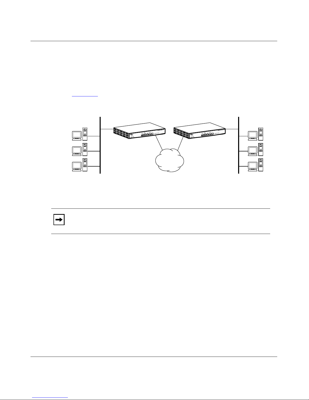
Branch-to-Branch Access
You can create a private wide area network (WAN) using two or more BayStack
820 ISDN Routers and enable two or more remote networks to connect to one
another to share resources.
Introduction
Figure 1-1
illustrates how two BayStack 820 ISDN Routers support a WAN
connection for branch-t o- branch access.
Your LAN #1
BayStack 820 ISDN Router
Figure 1-1. Two ISDN Networks Connected with Routers
BayStack 820 ISDN Router
ISDN
network
Your LAN #2
9394FA
Note: If the remote network uses an ISDN router from another vendor, the
router must support LAN-to-LAN communications.
Conventional Telephone Calls Over ISDN
You can connect telephone or fax dev ice s to t he two voi ce por ts on the router and
place a conventional voice call over a Public Switched Telephone Network
(PSTN) by dialing a regular telephone number. The call is established over a
single ISDN B channel and, if applicable, incurs the same kind of charges as a
regular phone call .
You can also configure convenient speeddial shortcuts to place phone calls in a
seamless manner.
206901-A 1-5
Page 36

Installation and Reference for the BayStack 820 ISDN Router
Figure 1-2 illustrates how a voice call is placed through the router over ISDN.
Phones connected to Router #1
ISDN
network
BayStack 820 ISDN Router
Figure 1-2. Conventional Telephone Calls over ISDN
Remote Dial-In Access
You can configure the BayStack 820 ISDN Router to allow remote users to
connect to your LAN and share resou rces when t hey are away fr om the off ice and
stay productive they are at home or on the road.
Using the call back feature, you can configure the router to allow dial-in access
for remote users while protecting your network against unauthorized users. After
a user dials in and is authenticated, the router disconnects the line and then calls
the user back at a preconfigured telephone number.Figure 1-3
BayStack 820 ISDN Router supports dial-in access by remote users.
Your LAN
PSTN
network
9438FA
illustrates how the
Figure 1-3. Dial-In Access to a LAN
1-6 206901-A
Telephone
network
ISDN
ISDN
BayStack 820 ISDN Router
Dial-in users
9393FA
Page 37

Internet Access
The BayStack 820 ISDN Rou ter provides Interne t access s o that eve ryone on you r
LAN can access the Internet and send and receive e-mail messages and files.
The router uses sin gle IP addr ess te chnolo gy t hat gre atly s implifi es conf igu ration.
When you establish a conn ectio n to the Int ern et, the router au tomati call y acquir es
the necessary I P a ddr ess . You do not need to apply for and assign an IP address to
each workstation or device on your network.
Introduction
Figure 1-4
illustrates how the BayStack 820 ISDN Router supports Internet
access.
Figure 1-4. Internet Access
Virtual Private Network
The BayStack 820 ISDN Router supports virtual private networks (VPNs), a
special type of connection that permits remote LANs to communicate with
another LAN over a publi c networ k, su ch as th e Inter net. When users c onnect this
way, you incur only local toll char ge s to your ISP. As a security measure, the data
can be encrypted before it travels across the VPN to ensure privacy.
BayStack 820
ISDN Router
Your internet
service provider
ISDN
9440EA
Note: Virtual private network ing and encrypt ion are optiona l features. Cont act
your Nortel Networks distributor for more information about purchasing this
feature.
206901-A 1-7
Page 38

Installation and Reference for the BayStack 820 ISDN Router
To create a VPN, a special connection, called a “tunnel,” is first established
between the two sites. Tunnels allow IP, IPX, and bridging traffic to flow across
IP networks, including NetBIOS information (for Windows networking)
encapsulated with in IP or IP X packet s. Through th e VPN tunnel, a ll resou rces and
applications on the remote LAN become available to the local site.
You can specify Data Encryption Standard (DES) encryption for user data
sessions through tunnels to assure privacy. The use of the various levels of
encryption within a router is subject to United States export control regulations.
You configure a VPN tun nel in a similar manner to a conventional telephone line.
Data is transferred only when a user connection is established, therefore
authentication is not required when you establish the tunnel. You must, however,
configure authen ticatio n informatio n for the connec tion profil e that is used for the
user data session flowing through the tunnel. After the tunnel is established, one
or more user data sessions can flow through the tunnel.
When a workstation on the LAN sends data to a resource reachable through a
VPN connection profile, a tunnel to the remote site is established and the VPN
user data session starts, beginning with a PPP authentication exchange.
When a remote site requests that a tunnel be established, the router searches for a
connection profile that matches the connection request. When the tunnel is
established, the remote site initiates a user s es si on to flow through that tunnel and
the router searches for a VPN connection profile that matches the request. When
the router verifies the matching VPN connection profile, the information in the
Profile is used to authe nticate the incoming call, and then data transfer begins.
Figure 1-5
illustrates how the BayStack 820 ISDN Router supports a VPN tunnel
through the Internet over an ISDN network.
Router #1 Router #2
Figure 1-5. VPN Tunnel Through the Internet Over ISDN
Internet
Secure data
VPN tunnel over ISDN
ISPISP
9395EA
1-8 206901-A
Page 39
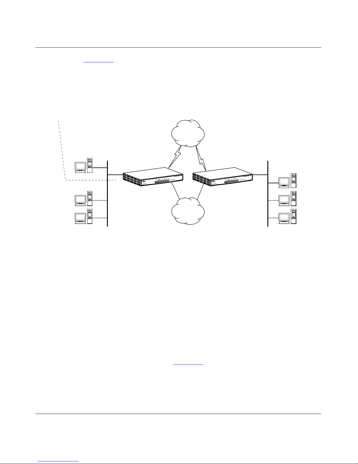
Introduction
Figure 1-6 illustrates how two BayStack 820 ISDN Routers installed in two
different locations su pport a privat e company netwo rk and highlig hts an importan t
feature of the router. Both public and private devices can physically reside on the
same LAN. Both of the routers are connected to the Internet and are also
connected to each other through the ISDN network, forming a private company
network.
Your LAN #1
Web server
Public:
206.112.113.xxx
BayStack 820
ISDN Router
Private:
192.168.168.xxx Private:
192.168.168.230
Public:
206.112.113.6
The
internet
ISDN
ISDN
BayStack 820
ISDN Router
Figure 1-6. Two Private Networks with Internet Access
In this illustration, all devices on both LANs (except for the Web server) are
configured to obtain their IP addresses automatically from the built-in DHCP
server in the BaySta ck 820 ISDN Router. Because these IP addresses are used
only in the local LAN environment, these devices naturally form a private
network with default network IP addresses of 192.168.168.xxx, and cannot be
accessed from the Internet. For a server to be accessible from the Internet, it must
be mapped to a TCP/UDP port in the BayStack 820 ISDN Router Manager
software using Network Addres s Translation.
Your LAN #2
Private:
192.168.170.xxx
Private:
192.168.170.230
9437FA
To enable LAN-to-LAN communications, you need to change the default private
network address (192.168.168.0) for one of the routers (for example, to
192.168.170.0 as illustrated in Figure 1-6
networks is secure because data is sent across the ISDN network through a direct
phone call.
206901-A 1-9
). The traffic between these two
Page 40

Installation and Reference for the BayStack 820 ISDN Router
Network Address Translation
Network Address Translation (NAT) is a powerful and economical way to
allowing Internet access to public servers on your netw ork (for example, an e-mail
server, an FTP server, or a Web server) without applying for or configuring public
IP addresses. NAT not only provides the benefits and administrative simplicity of
a using a single IP address ISP account, it provides the flexibility of a
configurable combination of secure, privately-addressed workstations and port
mapped publicly-accessible applications.
Figure 1-7
illustrate s how the rou t er supports NAT.
Public IP address
Public computers
on your public
Figure 1-7. Network Address Translation Support
Security Features
Internet
(IP address usually assigned by ISP)
LAN
ISDN Interface
LAN Interface
Private IP address
Private
workstations on
your LAN
The BayStack 820 ISDN Router provides severa l security features to help make
your network and data secure:
• Point-to-Point Protocol (PPP) and Password Authenti cation Protocol/
Challenge Handshake Authentication Protocol (PAP/CHAP) authentication
for all dial-in users and LAN-to-LAN communications
• Callback to confirm the identification of dial-in remote users
• ISDN C aller ID for incoming call authentication
1-10 206901-A
Page 41

• Private IP addressing scheme to prevent devices on your LAN from being
access by unauthorized users from outside your network
• Password protection for the console, Telnet, and BayStack 820 ISDN Router
Manager software
• DES encryption support for inter-office, non-VPN connections
• DES encryption support with Point-to-Point Protocol/Encryption Control
Protocol (PPP/ECP) negotiation for VPN connections
• IP packet filtering allows precise control of IP traffic on a per-connection
basis
Understanding the Installation Environment
Before you begin, t he re ar e some things you should understand a nd deci si ons you
need to make to ensure a smooth and successful installation. The information in
this section will help you understand and make those decisions.
Introduction
Understanding IP Addressing
An IP (Internet Protocol) address is a numeric identifier for a workstation or
device on a T ransmissi on Control Pr otocol/Int ernet Protoc ol (TCP/IP) networ k. IP
addresses follow the format nnn.nnn.nnn.nnn where nnn is a number between 0
and 255, for example , 192.168.168. 230 or 10.1.1.1. IP a ddresses enable de vices t o
talk to each ot her a nd both serve rs an d wor kstat ions on a ne twork mus t have an I P
address.
There are two types of IP addresses:
• Dynamic – A dynamic IP address may change. Dynamic IP addresses are
assigned to devices by an IP address server as the device needs it. Usually
there is a particular range (or scope) of IP addresses that your network uses.
With dynamic IP addressing, a device can have a different IP address every
time it connects to the network. Other devices need to know the device’s IP
address so that they can communicate with it and the IP address server
manages the assignment of IP addresses to the devices.
206901-A 1-11
Page 42

Installation and Reference for the BayStack 820 ISDN Router
• Static – A static (or fixed) IP address does not change. It is assigned to a
device permanently. The device has the same IP address every time it
connects to the network and is known to ot her devices on the network by that
IP address. Because the router on your network is also the gateway to other
networks and to the Internet, it must have a static IP address.The router is
shipped with a default IP address of 192.168.168.230 on its own private
network.
Understanding Static IP Addresses
If you are already using static IP addresses for your network workstations, you
have two options. You can:
• Keep using static IP addresses. If you do this, you must assign a static IP
address to the router and inform the workstatio ns that the router is the
gateway to remote networks.
• Change from static IP addresses to dynamic IP addresses by setting up the
router as a DHCP server. This is the recommended configuration. If you do
this, you mu st inform the workstations that they will be getting their IP
addresses assigned by the router.
Understanding DHCP Servers
The IP address server that manages the IP addresses is called a Dynamic Host
Configuration Protocol (DHCP) server. By default, the BayStack 820 ISDN
Router is set up to be your network’s DHCP server and it assigns IP addresses to
the devices on your network as they need them. This is the recommended
configuration for the router.
When you set up the rout er as your network’s DHCP server, you must inform the
workstations that they will be getting their new IP addresses assigned by the
router. To do this, you may need to change the configuration of each workstation
individually.
If you already have a DHCP server, you must inform server that the router is the
default gateway for the workstations.
1-12 206901-A
Page 43

Understanding Gateways and DNS Servers
When you access a remote LAN or Internet We b site through the router, it
functions as the gateway to other networks.
• Gateway – A gateway is a system that links two networks and enables them
to communicate with each other. When you use the router, the router is the
gateway that links your company’s network to another network or to the
Internet. Depending on your configuration, you may need to inform the
workstations that the router is the gateway to remote networks.
• DNS Server – A Domain Name Service (DNS) server translates
human-readable domain names into computer-readable IP addresses. For
example, the domain na me www.nortelnetworks.com for the Nort el Network s
Web site might translate t o t he I P address 134.177.3.28. After a domain name
is translated into an IP address, the workstations on your network can
communicate with the Web site. As a DHCP server, the BayStack 820 ISDN
Router automatically assigns DNS addresses to the workstations.
Introduction
Understanding How the BayStack 820 ISDN Router Works with Your
Existing DHCP Server
You can have only one IP address server on the network—either an existing
DHCP server or the BayStack 820 ISDN Router. If you already have a DHCP
server or do not want to use the router as a DHCP server, you must assign a static
IP address to the router and then let all of your workstations know that the router
is the gateway to remote networks.
After you assign a static IP address to the router, you must do two things on your
DHCP ser ver. You m ust:
• Exclude the static IP address that you reserved for the router from the range
(or scope) of IP addresses on the DHCP server.
• Inform the DHCP server that the router is the gateway and DNS proxy so that
the DHCP server can inform the workstations.
206901-A 1-13
Page 44

Page 45

Chapter 2
Installing the Router
This chapter describes t he ports and LEDs on the BaySt ack 820 ISDN Route r and
provides instructions for connecting the router to your LAN or WAN.
Before you install the route r , make sur e that you ar e famili ar with the physical a nd
environmental s peci fi cations of the BayStack 820 ISDN Router. For de ta il s, refer
to Appendix A, “
Technical Specifications.”
Getting to Know the BayStack 820 ISDN Router
The BayStack 820 ISDN Router does not require a keyboard or monitor for
operation. You can configure the router from the network using a Web browser
and the built-in BayStack 820 ISDN Router Manager software. You can also
Telnet to the router or attach the router to a workstation as a serial device and
configure the router dire ct ly usi ng the Command Line Int er fa ce (CLI ) commands.
206901-A 2-1
Page 46

Installation and Reference for the BayStack 820 ISDN Router
Front Panel
Table 2-1 describes the components on the fr ont panel of the BayStack 820 ISDN
Router (Figure 2-1)
Table 2-1. Front Panel Components of the BayStack 820 ISDN Router
Component Description
ISDN Port The ISDN port connects the router to the ISDN network. The
2 Analog Ports These analog POTS (Plain Old Telephone System) ports
.
port has either a U interface (labeled ISDN U) for use in North
America, or an S/T interface (lab ele d ISDN S/T) for use in t he
rest of the world.
(labeled Phone/Fax A and Phone/Fax B) connect regular
telephones, answering machines, or fax devices to the router.
4 10BASE- T Ethernet
Ports
These Ethernet ports connect individual network devices to
the router. You can also set port 4/Uplink to Uplink and
connect the router to a 10BASE-T Ethernet hub using a
straight-through cable. When this port is set to Normal, you
can connect a devic e to the port. This switch is located on the
bottom of the router.
10 LEDs These LEDs provide feedback on the router’s operation. The
Power LED always glows green when the router is turned on.
Several of the other nine LEDs indicate various activity or
error conditions. For a description of the LEDs, refer to
.
Ethernet ports LEDs
820 ISDN Router
B1 B2 A B 1 2 3 4
Figure 2-1
(with U interface shown)
Power/U Collision
Table 2-2 on page 2-3
illustrates the front panel of the BayStack 820 ISDN Router.
ISDN port
Phone/Fax
ports
ISDN Phone/Fax Ethernet
U A B 1 2 3 4/Uplink
Figure 2-1. Front Panel of the BayStack 820 ISDN Router
2-2 206901-A
9405EB
Page 47

Installing the Router
Table 2-2 describes the possible status of each LED on the front panel of the
router.
Table 2-2. Front Panel LED Status
Label Appearance Description
Power/U or
Power S/T
Collision S olid Green There is a network colli s ion.
B1 Solid Green An ISDN call is active on the B1 channel.
B2 Solid Green An ISDN call is active on the B2 channel.
A Solid Green A POTS call is active on phone/fax line A.
Solid Green and
Flashing Orange
Solid Green The router has synched and is working properly.
Orange The U interface or S/T interface has no line.
Off The router has no power.
Off There are no network colli s ions.
Solid Yellow A FIFO error occurred.
Flashing Green Router is passing data on the B1 channel.
Off There is no call on the B1 channel.
Flashing Green Router is passing data on the B2 channel.
Off There is no call on the B2 channel.
Flashing Green A POTS call is ringing phone/fax line A.
Off There is no activity on phone/fax line A.
The router is synching.
B Solid Green A POTS call is active on phone/fax line B.
Flashing Green A POTS call is ringing phone/fax line B.
Off There is no activity on phone/fax line B.
1, 2, 3, or
4/Uplink
206901-A 2-3
Solid Yellow A device (or hub) is attached to the Ethernet port and
the router is ready to service the client.
Flashing Yellow A packet is transmitting over the Ethernet connection.
Solid Green A polarity reverse error occurred.
Flashing Green A packet is being received over the Ethernet
connection.
Flashing Yellow
and Green
A partition out error occurred.
Page 48

Installation and Reference for the BayStack 820 ISDN Router
Back Panel
Table 2-3 describes the components on the back panel of the BayStack 820 ISDN
Router.
Table 2-3. Back Panel Components of the BayStack 820 ISDN Router
Component Description
DB-9 Auxiliary Connector This connector port connects the router directly to a
workstation (using a null modem cable) for router
configuration.
Power Receptacle The power receptacle connects to the router’s AC power
adapter.
On/Off Switch This switch turns the router on and off.
Figure 2-2
Ground outlet
illustrate s the back panel of the BayStack 820 ISDN Router.
Power receptacle
ON
Figure 2-2. Back Panel of the BayStack 820 ISDN Router
Auxiliary connectorOn/Off switch
AUX
9406EA
2-4 206901-A
Page 49

Preparing for an ISDN Connection
The ISDN communications connection provides the link between the router and
the public switched networ k. Before you conne ct to an ISDN network, be sure you
meet the following requir em en ts.
North America Requirements
For North American services, make sure you:
• Order the appropriate installation and service from your local telephone
company (Telco).
• If you require Caller Line Identification (CL I) for security, y ou order the CLI
option from your local carrier.
• Have an ISDN U connection on the wall outlet.
• Order the appropriate Internet access service from your Internet service
provider (ISP), if you require Internet service.
Installing the Router
• Know the type of switch at your Telco. The router auto-detects the type of
switch. Knowing the swit ch type at your Telco can help you verify that the
router detected the correct switch.
• Know the configuration mode of your ISDN line. You can configure the
router in the standard National ISDN-1 mode or in a manufacturer-specific
mode.
• Know the Service Profile Identifier (SPID) number(s) assigned to your
devices. The router usually automatically detects the associated SPID
numbers, but if it does not, you must provide them.
• Know the directory number(s) assigned to your ISDN line.
206901-A 2-5
Page 50

Installation and Reference for the BayStack 820 ISDN Router
European Requirements
For European services, make sure:
• You have an ISDN S/T connection on the wall outlet.
Caution S/T Interface Only: This product is not intended for direct
connection to t he public switched network or to ot her exposed plant networks.
Always connect this product to such switched or exposed plant networks
through a certified (by the local, regional, or national safety agency and
telecommunicati ons author it y) , isol at ing-type network terminating device
(CSU, DSU, NT1, NCTE, or similar device) that provides overvoltage
protection. This caution applies only to products with an S/T interface.
• Your ISDN circuit conforms to EURO-ISDN (ETSI) standards.
• You know the ISDN number(s) of your ISDN line.
• If you require Caller Line Identification (CL I) for security, y ou order the CLI
option from your local carrier.
2-6 206901-A
Page 51

Installation Worksheet
Internet Service (if required)
ISP User Name:_________________________________________
The user name you enter to log on to your ISP account.
ISP Password:___________________________________________
The password you enter to log on to your ISP account.
ISP Connection Phone Number:____________________________
The primary phone number you dial to access your ISP account.
Telephone Company Information
SPID Number:_____________________________________
SPID Number:_____________________________________
SPID (Service Profile Identifier) numbers are provided by your telephone
company when you install an ISDN line.
Installing the Router
Switch Type:____________________________________________
The switch type is provided by your telephone company when you install an
ISDN line.
Directory Number:_______________________________________
Directory Number:_______________________________________
Directory Number:_______________________________________
Directory Numbers are the phone numbers assigned to the B channels.
Depending on your switch type, you may have 0, 1, 2, or 3 Directory
Numbers.
Choosing IP Addresses
If you are setting up LAN-to-LAN communications, each network must have a
unique range of IP addresses. When you use the router’s built-in DHCP feature,
the router automatically assigns IP addresses to the network workstations.
You can change the pri vat e I P add ress of the router and, consequently, the pool of
addresses from which the DHCP server assigns addresses.
206901-A 2-7
Page 52

Installation and Reference for the BayStack 820 ISDN Router
Connecting the BayStack 820 ISDN Router to the Network
Because the BaySt ack 820 ISDN Router is a DHCP server wi th its own private IP
addressing scheme, you must use a standalone workstation to configure the
BayStack 820 ISDN Ro uter for the first time.
Note: Before you begin, make sure that the workstation you use to set up the
router is not connected to your network. If you do not have a standalone
workstation, temporarily disconnect a workstation from the network. The
workstation you use to configure the router must have TCP/IP loaded and be
configured to obt ain and IP address automatically (DHCP op ti on) . For det ai ls ,
refer to “Configuring a Workstation to Use the Router” on page 2-12
Installing the BayStack 820 ISDN Router
To install the BayStack 820 ISDN Router:
1. Place the router on a flat surface.
.
Caution: Use a Green/Yellow Protected Earth (PE) wire and a star washer to
ground the metal case of t he route r to the nearest PE ter mina l. The router must
remain grounded during normal operation. (Before you connect the PE wire,
use a Phillips-head screwdriver to remove the plastic protector from the
ground outlet on the back of the router.)
2. Connect the power cord to the power adapter.
3. Connect the power adapter to the power receptacle on the back of the
router and connect the power cord to an AC wall outlet (Figure 2-3)
9625FA
Figure 2-3. Connecting the Power Cord
.
2-8 206901-A
Page 53

Installing the Router
Connect one end of the included ISDN cable to the port labeled ISDN/U
4.
(or ISDN S/T) on the front of the router and connect the other end to the
ISDN wall outlet (Figure 2-4)
Figure 2-4. Connecting the ISDN Cable
5.
Connect one end of the included 10BASE-T LAN cable to the Ethernet
.
9626FA
port labeled 1 on the fr ont o f th e r out er and t he othe r end t o th e Ether net
port on the workstat ion (Figure 2-5)
.
Figure 2-5. Connecting a Workstation
206901-A 2-9
9628FA
Page 54

Installation and Reference for the BayStack 820 ISDN Router
6. Turn the router on and verify that the Power LED glows green and then
flashes green and orange indicating that the router is functioning
properly (Figure 2-6)
ON
Figure 2-6. Turning the Router On
Restart the workstation.
7.
.
9627FA
Restarting the workstation enables the router (as a DHCP server) to give the
workstation an IP address from its private network, forming a mini-network
between the router and the workstation.
8. Connect up to four devices to the router.
a. Connect one end of the 10BASE-T LAN cable to an Ethernet port on
the front of the router.
b. If necessary, disconnect the workstation from the network.
c. Connect the other end of the 10BASE-T LAN cable to the Ethernet
port on the workstat ion.
If you want to connect more than four devices to the router, you can connect
an external hub to the 4/Uplink port using a straigh t- thr oug h ca ble and set the
port to Uplink. For details, refer to “
Connecting the BayStack 820 ISDN
Router to a Hub” next.
2-10 206901-A
Page 55

Connect up to two devices to the POTS ports on the front of the router
9.
(Figure 2-7)
.
9629EA
Figure 2-7. Connecting Devices to the POTS Port
Connecting the BayStack 820 ISDN Router to a Hub
Installing the Router
The included 10BASE-T LAN cable is a straight-through cable used to connect a
workstation to an Ethernet port. By default, all four of the Ethernet ports on the
router are set as Normal ports. However, you can set the 4/Uplink port to Uplink
and connect a the router to a hub. When you use a straight-through cable and set
port 4/Uplink to Uplink, you eliminate the need for a crossover cable.
To connect the router to a hub:
1. Connect one end of t h e 10BASE- T LAN c able t o t he 4/Uplink port on the
front of the router and connect the other end to any Normal port on the
hub (Figure 2-8)
.
350T
9630EA
Figure 2-8. Connecting to a Hub
206901-A 2-11
Page 56

Installation and Reference for the BayStack 820 ISDN Router
2. Locate the small r ect angul ar hol e on the bot tom of the r out er and set the
switch to t he Uplink pos ition (Figure 2-9
UPLINK
NORMAL
9624FA
Figure 2-9. Setting the Uplink Port
).
Configuring a Workstation to Use the Router
All workstations on the LAN that communicate with the BayStack 820 ISDN
Router, either to confi gure th e rou ter or to use the rout er for network acc ess, must :
• Have an Ethernet interface properly installed.
• Be connected to the router either directly or through an external hub.
• Have TCP/IP installed.
• Be configured to obtain an IP address from a DHCP server or be configured
with a static IP address.
Note: You can use any workstation configured with TCP/IP to communicate
with or through the router. If you want to configure non-TCP/IP workstations,
refer to the workstation documentation.
2-12 206901-A
Page 57
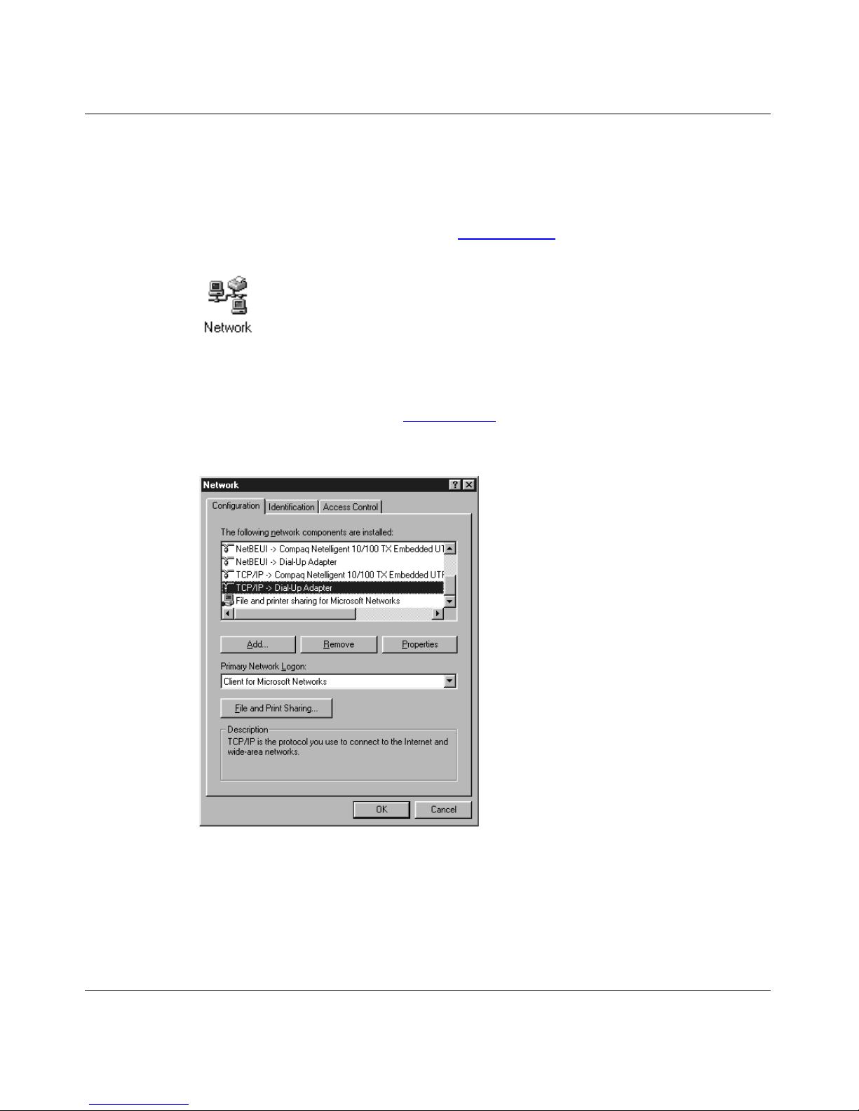
Installing the Router
To configure a Windows 95 or Windows 98 workstation with TCP/IP:
1. From the Windows Start menu, choose Settings > Control Panel.
The Control Panel window opens.
2. Double-click the Network icon (Figure 2-10).
Figure 2-10. Windows Network Icon
The Network dialog box (Figure 2-11) opens and displays the Configuration
tab that shows a list of installed network components.
Figure 2-11. Network Dialog Box – Configuration Tab
206901-A 2-13
Page 58

Installation and Reference for the BayStack 820 ISDN Router
3. Select TCP/IP in the list of instal led network components and the n click
Properties.
The TCP/IP Properties dialog box (Figure 2-12)
opens.
Figure 2-12. TCP/IP Properties Dialog Box – Properties Tab
4.
Click each tab in the TCP/IP Properties dialog box, confirm each setting
as described in Table 2-4
, and then click OK.
Table 2-4. TCP/IP Properties Settings
TCP/IP Properties Tab Setting
IP Address Select the Obtain IP address automatically option.
Bindings Select the Client for Microsoft Networks check box and File
and printer sharing f or Microsoft Networks check box.
Gateway Clear all fields.
DNS Configuration Select the Disable DNS option.
5. With the router connected to the LAN and turned on, reboot the
workstation.
2-14 206901-A
Page 59

Installing TCP/IP on a Workstation
Depending on your existing configuration, you may have to install TCP/IP on
your IP workstations if it is not already installed. If you have trouble with the
following procedure, refer to your operating system documentation.
You may need your Microsoft® Windows 95®, Windows 98®, or Windows NT
CD to complete the installation.
Note: New Windows 98 workstation installations are already co nfi gur ed wi th
TCP/IP. They are also already configured to obtain an IP ad dress automati cally
(DHCP).
To install TCP/IP on a workstation:
1. From the Windows Start menu, choose Settings > Control Panel.
The Control Panel window opens.
Installing the Router
®
2. Double-click the Network icon (Figure 2-13).
Figure 2-13. Windows Network Icon
206901-A 2-15
Page 60

Installation and Reference for the BayStack 820 ISDN Router
The Network dialog box (Figure 2-14) opens and displays the Configuration
tab that shows a list of installed network components.
Figure 2-14. Network Dialog Box – Configuration Tab
Click Add.
3.
The Select Network Component Type dialog box (Figure 2-15)
Figure 2-15. Select Network Component T ype Dialog Box
opens.
2-16 206901-A
Page 61

Select Protocol in the list and then click Add.
4.
Installing the Router
The Select Network Protocol dialog box (Figure 2-16)
Figure 2-16. Select Network Protocol Dialog Box
In the Manufacturers area, select Microsoft.
5.
6. In the Network Protocols area, select TCP/IP.
opens.
7. Click OK and follow the prompts on your screen.
After you install TCP/IP on a workstation, follow the procedures in “
a Workstation to Use the Router” on page 2-12.
Configuring
206901-A 2-17
Page 62

Page 63

Chapter 3
Getting Started
This chapter describes how to use the BayStack 820 ISDN Router Manager
software, configur e the BayStack 820 I SDN Router for basi c ISDN access, a nd set
the router’s system time.
Using the BayS tack 820 ISDN Router Manager Softwar e
The BayStack 820 ISDN Router Manager software is built in to the router to
provide easy configuration and management. To configure your router, you can
use popular Web browsers such as Netscape Navigator version 4.5 or later or
Internet Explorer version 4.01, SP1 (or later) or use a null modem cable or a
Telnet application to issue commands with the command line interface (CLI).
The router comes with a basic feature set installed. If you purchased additional
features from your distributor, you are provided a feature ke y. You can use the
feature key to update your system with the new features. For details, refer
to“Upgrading the Firmware and Software Features” on page 8-3
Before you use the BayS tack 82 0 ISDN Rou ter Manager softwa re, make sure that :
• The Web browser is configured for LAN access.
• The workstation you use t o conf igure the rou ter has an IP a ddress on t he same
network as the router. For details, refer to Chapter 2, “Installing the Router
.
.”
206901-A 3-1
Page 64

Installation and Reference for the BayStack 820 ISDN Router
Connecting to the BayStack 820 ISDN Router
To connect to the BayStack 820 ISDN Router:
1. In the Address or Location box of your Web browser, enter the default
private IP address of the router (192.168.168.230).
The Login dialog box (Figure 3-1)
opens.
Figure 3-1. Login Dialog Box
Enter your password.
2.
If you are logging on for the first time, enter the factory default password
(which is “password”). For security purposes, the password is displayed as a
string of asterisks (*).
The default pass word is al ways ente red in the pas sword field, even i f you set a
new one.
3. Click Log On.
If you are logging in for the first time, the BayStack 820 ISDN Router
Manager customization dialog box opens (Figure 3-2)
customize the user interface. For details, refer to “
where you can
Customizing the BayStack
820 ISDN Router Manager Interface” next.
3-2 206901-A
Page 65

Getting Started
Customizing the BayStack 820 ISDN Router Manager Interface
When you log on to the BayStack 820 ISDN Router for the first time, the
BayStack 820 ISDN Router Manager customization dialog box (Figure 3-2)
opens, which displays options for customizing the BayStack 820 ISDN Router
Manager interface for your specific needs.
The options you select in this dialog box determine the configuration menu items
and buttons displayed in the so ftware. For e xample, if you select only the Basic
Internet Access che ck box, the BayStack 82 0 ISDN Router Manager displa ys only
buttons and dialog boxes related to basic Internet access. You can select multiple
check boxes to configure multiple router settings.
The interface options re ma in in effect until you change them. You can change the
user interface at any time.
To customize or change the user interface:
1. Choose System Tools > Customize User Interface.
The BayStack 820 ISDN Router Manager customization dialog box
(Figure 3-2) opens.
Figure 3-2. BayStack 820 ISDN Router Manager Customization Dialog
Box
206901-A 3-3
Page 66

Installation and Reference for the BayStack 820 ISDN Router
2. Use the information in Table 3-1 to select the interface configuration
options and then click Next.
Table 3-1. BayStack 820 ISDN Router Manager Interface Customization Options
Option Description
Access to/from Remote Site Select this check box if you want to configure connections
to other LAN sites (bran ch- to-branch access), so that users
at each site can sha re re so urc es . For details on configuring
remote access options, refer to Chapter 4, “
Remote Office Access.”
Dial-in Access for Off-Site Users Select this check box if you want to enable remote users
using a stand-alone workstation to dial in and access
resources on your network . For details on con figuring dial-i n
access options, refer to Chapter 5, “
User Access.”
Share Netware (IPX) Resource Select this chec k box if you use Novell servers on your
network and want to allow remote LANs or offices to share
those resources. IPX resources are configured as needed
for individual connection profiles.
Configuring Dial-In
Configuring
Basic Internet Access Select this check bo x i f yo u w a nt to c onfi gure basic Internet
access for all of your LAN users. For details on configuring
Internet access options, refer to Chapter 6, “
Internet Access.”
Internet Access with Advanced Configuration Select this check box if you want to configure advanced
options, for exam ple, chan ge the ro uter’s private IP address
or assign a public IP address. For details on configuring
advanced options, refer to Chapter 6, “Configuring Internet
Access.”
Configuring
3-4 206901-A
Page 67

Getting Started
Overview of the B ayStack 820 ISDN Router Manager
Software
Before you begin configuring the BayStack 820 ISDN Router, take a moment to
familiarize yourself with the BayStack 820 ISDN Router Manager soft ware main
page (Figure 3-3)
Figure 3-3. BayStack 820 ISDN Router Manager Software Main Page
206901-A 3-5
Page 68

Installation and Reference for the BayStack 820 ISDN Router
Table 3-2 describes the parts of the BaySta ck 820 ISDN Router M anager softwar e
main page.
Table 3-2. Parts of the BayStack 820 ISDN Router Manager Software
Main Page
Part Description
Main Menu Click a menu item to display configuration dialog boxes in
the Configuration window. You can configure connection
profiles, protocols, and system monitoring tools.
Configur ation Pane Configur ation dialog boxes are displayed in this area of the
page.
Message Pane The Message Wi ndow is di splayed in this pane. The system
status and error messages provided immediate feedback
on actions you perfo rm. For ex ample, if you con fig ured y our
password incorrectly, an error message is displayed in this
window.
Current Status Dialog Box
The Current Status dialog box (Figure 3-4) displays router statistics and the
current status of all router interfaces. This dialog box opens as a separate Web
browser page from the main BayStack 820 ISDN Router Manager We b browser
page and opens automatically eac h time you st art the BaySt ac k 820 ISDN Router
Manager software or customize the software interface.
Although the BayStack 820 ISDN Router Manager main page times out after a
period of inactivit y, this page does not. It remains operational prov id ing feedback
on the router as long as the window is active. If you close this page, you can
reopen it.
3-6 206901-A
Page 69

Getting Started
To open the Current Status dialog box:
• Choose Monitoring > System Status.
The Current Status dialog box (Figure 3-4)
opens.
.
Figure 3-4. Current Status Dialog Box
Table 3-3 describes each statistic in the Current Status dialog box.
Table 3-3. Current Status Statistics Fields
Field Description
Device Displays a list of all interfaces, including both the physical interface
(LAN port and ISDN port) as well as logical connections that have
been activated (for example, connections to the Internet or remote
offices and active VPN sessions).
Status Displays the current state of the interface.
• For the LAN, Up indicates that the interface is connected and
functioning. Down indicates that the interface is not connected.
• For ISDN, Up indicates that the line is functioning.
• For ISDN B channels, if the interface is active, t he profile name or
voice call is displayed. NoCall indicates that an ISDN B channel
is idle.
• For VPN tunnels, if the interface is active, the profile name is
displayed. If the VPN tunnel is inactive, it is not displayed.
Xmt Pkts Displays the number of packets transmitted by the interface.
Rcv Pkts Displays the number of packets detected on the interface.
Err Pkts Displays the number of error packets received by the interface.
206901-A 3-7
Page 70

Installation and Reference for the BayStack 820 ISDN Router
To disconnect an interface:
• Select the interface in the list and then clic k Disconnect.
Note: You can disconnect only switched connections, for example, ISDN
switched connection profiles or VPN sessions. You cannot disconnect a voice
call.
To reset all calculated values to zero:
• Select the interface in the list and then click Clear.
Creating a Connection Profile
Connection profiles are the foundation of all remote communications. A
connection profi le co nta ins all of th e i nformat ion t hat t he rou ter n eeds t o e stablis h
a connection with any user or net work that co mmunicate s with the r outer. You can
create several types of connection profiles, including:
• Branch-to-branch connection profile to support branch-to-branch remote
access. For details, refer to Chapter 4, “Configuring Remote Office Access
.”
• Dial-in user connection profile to support remote users dialing in to your
network. For details, refer to Chapter 5, “Configuring Dial-In User Access.”
• Internet access connect ion profi le to suppor t basi c Interne t access. Fo r detail s,
refer to Chapter 6, “Configuring Internet Access
.”
• VPN access connection profile to support a virtual private network (optional
feature). For details, refer to Chapter 4, “Co nfiguring R emote Office Access
.”
Profile information includes dial-up phone numbers, authentication information
(the local user name and password and possibly the remote site user name
password). Depending on the type of profile you are creating, other information
may be required.
3-8 206901-A
Page 71

Configuring ISDN Port Settings
Before the router can support remote communications, you need to configure the
router’s ISDN settings. To configure the ISDN settings, you must have the
information in the “Installation Worksheet” on page 2-7
Switches in North America often require Service Profile Identifier (SPID)
numbers. In many such cases, the router can automatically detect both the switch
type and the SPID numbers. Certain types of North American switches can also
detect the ISDN Directory Numbers. Normally, if the router is connected to this
type of switch, all of the required information is automatically detected when t he
ISDN line is initialized. If the router cannot detect a Directory Number, you must
enter it manually. If you select Auto Detect as the ISDN switch type, you must
enter the ISDN Direct ory Numbers.
Note: If you need more detailed information than this section provides, want
to configure advanced ISDN settings, or want to configure only an Internet
access connection profile, refer to Chapter 6, “Configuring Internet Access
Getting Started
.
.”
Configuring Basic ISDN Port Settings
To configure the ISDN interface for remote communications:
1. Choose Configuration > WAN Interfaces > ISDN.
The Port Configuration, ISDN dialog box (Figure 3-5)
Figure 3-5. Port Configuration, ISDN Dialog Box
opens.
206901-A 3-9
Page 72

Installation and Reference for the BayStack 820 ISDN Router
2. Use the information in Table 3-4 to configure the ISDN port settings and
then click APPLY.
Table 3-4. Port Configuration, ISDN Dialog Box Fields
Field Description
ISDN Switch Type The switch type of your ISDN line (sup plied b y your ISDN pr ovi der). Sele ct from the
following:
• Auto Detect (North America ONLY)
• Japan (INS Net)
• Europe (ETSI) - default switch type for an S/T interface
• NT DMS-100
• NI-1 - default switch type for a U interface
• ATT5ESS (Multipoint)
• ATT5ESS (Point-to-Point)
• Taiwan
• OCN
• Permanent 64K
• IDSL/Perm 128K
SPID1
SPID2
Number of Directory
Phone Numbers
Directory Phone
Number 1
Enter the Service Profil e Identifier (SPID) numbers supplied by your ISDN service
provider. Used only in North America, SPID numbers are uni qu e ide ntif ier nu mb ers
provided by your local telephone company when you install an ISDN line. Usually,
two SPID numbers are provided, but sometimes one and even none is provided.
In many cases, both SPID numbe rs are requi red if you w ant to conn ect usin g two B
channels. A SPID number is typically 14 digits long and consists of the 10-digit
telephone number (area code plus phone number), followed by the digits “0101.”
Other variations of this number are possible and your telephone company can
provide you with the c orrect in format ion for y our ISD N line. Th e SPID numb ers ma y
be automatically detect ed an d ente red if you sele ct Auto Dete ct as the ISDN Sw itch
Type.
This field is displ ayed wh en you se lect N T DMS-100 , NI-1, or ATT5ESS (Multipoint)
as the ISDN Switch Type.
Select the number of additional Directory Numbers yo u w a nt t o s pe ci fy. Select from
0, 1, 2, or 3.
This field is displayed when you select Auto Detect, Japan, Europe, NT DMS-100,
NI-1, ATT5ESS, or Taiwan as the ISDN Switch Type.
Enter the first Directory Number.
This field is displayed when you select 1, 2, or 3 as the number of directory phone
numbers.
3-10 206901-A
Page 73

Table 3-4. Port Configuration, ISDN Dialog Box Fields (continued)
Field Description
Getting Started
Directory Phone
Number 2
Directory Phone
Number 3
Enter the second Directory Number.
This field is displayed when you select 2 or 3 as the number of directory phone
numbers.
Enter the third Directory Number.
This field is displayed when you select 3 as the number of directory phone
numbers.
Setting the System Time
The BayStack 820 ISDN Router maintains a real-time clock that is automatically
set to the local time of the management workstation the first time you connect to
the BayStack 820 ISDN Router Manager software.
The time is used to provide time stamps for Connection Log and System Log
entries and to determine Internet access time restrictions (see “
Access Time Restrictions” on page 6-11).
Because the router does not use a backup battery for the real-time clock, the time
is not maintained across system resets or power cycles. Therefore, after a reset or
power cycle, you must connect to the router to reset the clock. The time zone and
daylight savings time indicator are saved across power cycles.
Setting Internet
Note: The System Time menu item is not displayed if you selected only the
Basic Internet Access check box in the BayStack 820 ISDN Router Manager
configuration dialog box. If you want to be able to change the system time,
select any other check box. For details, refer to “
Customizing the BayStack
820 ISDN Router Manager Interface” on page 3-3.
206901-A 3-11
Page 74

Installation and Reference for the BayStack 820 ISDN Router
To view or change the system time settings:
1. Choose Configuration > Advanced > System Time.
The System Time Setting dialog box (Figure 3-6)
Figure 3-6. System Time Setting Dialog Box
Select the route r’s Time Zone from the list.
2.
3. To have the router automatically change it s time according to daylight
opens.
saving time, select the Daylight Saving Time check box.
4. Click Apply.
The Current Router Time and Time Zone are updated and displayed.
3-12 206901-A
Page 75

Configuring Remote Office Access
This chapter describes how to configure remote office access connection profiles
for branch-to-branch access. You can configure remote office access by ISDN or
configure a virtual private network (VPN) if you purchased this optional feature.
Configuring Remote Office Access by ISDN
Chapter 4
To enable your local LAN to access a remote LAN, you must configure a remote
office connection profile for the BayStack 820 ISDN Router at each site (one
profile for the remote router and one for the local router).
The remote site does n ot need to have a BayStack 820 ISDN Router, and may not
be configurable by the local administrator. In either case, make sure that you
configure the router to match the requirements of the remote site.
To configure remote office access, you must select the Access to/from Remote
Site check box in the BayStack 820 ISDN Router Manager customization dialog
box. If you want to configure NetWare resources for remote access connections,
select the Share NetWare (IPX) Resource check box. For details, refer to
“Customizing the BayStack 820 ISDN Router Manager Interface” on page 3-3
Before you configure a remote office connection profile, you need to configure
the ISDN connection. For details, refer to “
page 3-9.
Configuring ISDN Port Settings” on
.
206901-A 4-1
Page 76

Installation and Reference for the BayStack 820 ISDN Router
Configuring a Remote Office Access Connection Profile
To create a remote office access connection profile:
1. Select Configuration > Connection Profiles and then do one of the
following:
• If you configured at least one connection profile, the Connection
Profile Summary dialog box (Figure 4-1)
• If you are configuring a connection profile for the first time, the
Interface Configuration dialog box (Figure 4-2)
Step 3
.
opens. Proceed with Step 2.
opens. Proceed with
Figure 4-1. Connection Profile Summary Dialog Box
Do one of the following:
2.
• To create a new connection profile, select New from the list and then
click NEXT.
• To edit an existing connection profile, select it in the list and then
click NEXT.The Interface Configuration dialog box (Figure 4-2)
opens.
Figure 4-2. Interface Configuration Dialog Box
4-2 206901-A
Page 77

Configuring Remote Office Access
Select ISDN as the interface.
3.
4. Select the Remote Offi ce Acce ss conf igurat ion type and then cli ck NEXT.
The configuration type options displayed in this dialog box depend on the
selections you made in the BayStack 820 ISDN Router Manager
customization dialog box. For details, refer to “
Customiz ing the BayS tack
820 ISDN Router Manager Interface” on page 3-3.
The Connection Profi le Configuratio n, Remote Off ice Access by ISDN di alog
box (Figure 4-3)
opens.
Figure 4-3. Connection Profile Configuration, Remote Office Access by
ISDN Dialog Box
Use the information in Table 4-1 to configure the se ttings and the n do one
5.
of the follo wing:
• If you set the Call Direction to Incoming, click APPLY.
• If you set the Call Direction to Outgoing or Both, click APPLY and
TEST or click ADVANCED for more options.
You must still click APPLY and TEST even if the other end of the
connection has not been configured. When you click APPLY and TEST,
the BayStack 820 ISDN Router attempts to place a call to the remote site
and log in.
206901-A 4-3
Page 78

Installation and Reference for the BayStack 820 ISDN Router
Monitor the Message Window for any progress messages. If the test is
successful, the router disconnects from the remote site. If the test is not
successful, make changes to the configuration based on progress
messages that appear in the Message Window, and then try again.
Table 4-1. Connection Profile Configuration, Remote Office Access by ISDN
Fields
Field Description
Profile Name Enter a unique name for this profile.
Call Direction Select a call direction. Choose from:
• Incoming Only – Select this direction if the remote site will only dial in to the
router.
• Outgoing Only – Select this direction if the router will only dial out to the remote
site.
• Both – Select this direction if the remote site will dial in and the router will dial
out. The default direction is Both.
NOTE: If you set the Call Direction to Incoming, the Remote Phone Number, My
System Name, and My System Password fields are not displayed unless Call Back
is set to Yes. If only incoming calls are allowed with this profile, the APPLY and
TEST button is displayed.
Call Back Select whether to en abl e the call back security featu re. When you enable call back,
the router answers an incoming call, authenticates the dial-in user’s remote system
name and remote password, disc onn ec ts the ca ll, and then dials the remote user’s
call back number to reconnec t.
NOTE: If you set Caller ID Authen. to Yes in the Connection Profile Configuration,
Remote Office Access (advanced) dialog box, the call is not answered and the
router dials the remote user’s call back numbe r to connec t.
This field is displayed when you set Call Direction to Incoming or Both.
Call Back Phone
Number
Remote Phone
Number
My System Name Enter the n ame that the re mo te syste m us es to recog nize your n etwork. This field is
My System Password Enter the password the remote sy ste m uses to authe nti cate your system. This field
Incoming
Authentication
Enter the remote user’s call back phone number.
This field is displayed when you set Call Back to Yes.
Enter the ISDN phone number of the remote router connected to the remote LAN.
case sensitive, so nortel is not the same as Nortel or NORTEL.
is case sensitive, so nortel is not the same as Nortel or NORTEL.
Displays the method used for authentication. The router first uses CHAP to
authenticate the incoming call. If CHAP authentication fails, then PAP is used.
4-4 206901-A
Page 79

Configuring Remote Office Access
Table 4-1. Connection Profile Configuration, Remote Office Access by ISDN
Fields
Field Description
(continued)
Remote System
Name
Remote System
Password
Enter the system name of the remote network that is dialing in. This field is case
sensitive, so nortel is not the same as Nortel or NORTEL.
Enter the password the router uses to authenticate the remote sy stem. This field is
case sensitive, so nortel is not the same as Nortel or NORTEL.
Configuring Remote Access Profile Advanced Options
To configure remote access profile advanced options:
1. In the Connection Profile Configuration, Remote Office Access by ISDN
dialog box (Figure 4-3)
The Connection Profil e Configuration, Remote Office Access by ISDN
(Advanced) dialog box (Figure 4-4)
, click Advanced.
opens.
Figure 4-4. Connection Profile Configuration, Remote Office Access by
206901-A 4-5
ISDN (Advanced) Dialog Box
Page 80

Installation and Reference for the BayStack 820 ISDN Router
2. Use the information in Table 4-2 to configure the advanced settings and
then do one of the following:
• Click OK to save your changes.
• Click Multilink to configure Multilink opt ions. For details, refer to
“
Configuring Remote Office Access Connection Profile Multilink
Options” on page 4-8.
Table 4-2. Connection Profile Configuration, Remote Office Access by ISDN
(Advanced) Fields
Field Description
Data Service Select the type of data service from the list. Select from Data Over Voice Channel,
64K, 56K, or Auto. Select Auto unless you know that the speed required by the
other end of the connection requires either 64K or 56K. Select Data Over Voice
Channel if you want to support data calls over a standard voice port. For more
information on Data over V o ice, refer to “
on page 6-5.
Remote Sub-Address Enter an optional subaddress of the remote server to be used when dialing the
remote router.
Configuring Advanced ISDN Port Settings”
Caller ID Authen. Select whether to enable caller ID authentication for this profile. When you enable
caller ID authentication, the router verifies the incoming caller ID before accepting
the call. This option may require a special service from your ISDN service provider.
Caller ID Number Enter the caller ID phone number to authenticate.
This field is displayed when you set Caller ID Authen. to Yes.
ST AC Compression Select whether to use ST AC com pression. STAC compression allows outgoing data
to be compressed to achieve higher throughput, and compressed incoming data to
be recognized. The ability to use compression depends upon the capabilities of
your ISP.
Idle Timeout Enter the number of seconds of inactivity for the connection before the router
disconnects the call. You can set the idle timeout from 0 to 3600 seconds. The
default setting is 120 seconds. If you set the timeout to 0, the connection never
times out.
Enable IP Select whether to enable IP routing over a connection using this profile. When you
enable IP routing, th e router routes IP data packets to the ap propriate server or h ost
according to entries in the IP routing table.
IP RIP Select whether to enable IP Routing Information Protocol (RIP). When you enable
IP RIP, the router receives RIP broadcast data from other routers, and broadcasts
the routing table and routing table updates as necessary.
IP RIP Version Select the version of IP RIP to use.
This field is displayed when you set IP RIP to Yes.
4-6 206901-A
Page 81

Configuring Remote Office Access
Table 4-2. Connection Profile Configuration, Remote Office Access by ISDN
(Advanced) Fields
Field Description
(continued)
Set as IP Default
Route
Remote IP Address Enter the IP address of a destination workstation on a network reachable through
Remote IP Netmask Enter the IP subnet mask of the remote IP address.
Enable IPX Select whether to enable IPX routing over a conne ction using this profile. When you
IPX RIP/SAP Select whether to enable IPX Routing Information Protocol (RIP) and Service
Set as IPX Default
Route
Select whether to set this connection profile as the IP default route. When you set
this profile as the IP default route, users on your local LAN obtain their Internet
access through a connection to the remote LAN.
NOTE: If you allow Internet access in this manner, make sure you have not
configured any Internet access connection profiles.
this connection profile.
This field is displayed when you set IP Default Route to No.
This field is displayed when you set IP Default Route to No.
enable IPX routing, the router routes IPX data packets to the appropriate server or
host according to entries in the IPX routing table.
This field is displayed when you select Share NetWare (IPX) Resource in the
BayStack 820 ISDN Router Manager customization dialog box.
Advertising Protocol (SAP). Whe n you enabl e IPX RIP/SAP, the router receives RIP
and SAP broadcast data from other routers, and broadcasts the routing table and
routing table updates as necessary.
This field is displayed when you set Enable IPX to Yes.
Select whether to set this connection profile as the IPX default route. When you
enable this profile as the IPX default route, the router uses this connection if no
other route for an IPX packet is found in the routing table.
This field is displayed when you select Share NetWare (IPX) Resource in the
BayStack 820 ISDN Router Manager customization dialog box.
Remote IPX Network
Number
Enable Bridging Select whether to enable bridging to non-IP or non-IPX protocols, for example,
206901-A 4-7
Enter the IPX network number of a network reac hable through this connection. If
you enabled IPX as the default route for this connection, an entry in this field is not
required.
This field is displayed when you set IPX Default Route to No.
SNA, Appletalk, and NetBEUI. You may also need to enable bridging if the remote
connection supports only bridging.
NOTE: If you enabled IP routing or IPX routing, routing takes precedence. For
example, if you enabled both bridging and IP routing, IP data is routed, and all
non-IP data is bridged.
Page 82

Installation and Reference for the BayStack 820 ISDN Router
Table 4-2. Connection Profile Configuration, Remote Office Access by ISDN
(Advanced) Fields
Field Description
Enable Encryption Select whether to enable DES encryption. When you enable encryption the router
encrypts all data before it is sent out to the WAN, and decrypts data when it is
received from the WAN.
This field is displayed when the workstation is connected to the router over a local
LAN.
Encryption Key Enter the DES encryption key to be used by other systems to establish a
connection with your system. You need to enter a must be a hexadecimal number
with either 56 bits (14 digits).
This field is displayed when you set Enable Encryption to DES.
(continued)
Confirm Encryption
Key
Re-enter the DES encryption key to confirm that you entered it correctly.
This field is displayed when you set Enable Encryption to DES.
Configuring Remote Office Access Connection Profile Multilink
Options
The use of multiple B channel s for a si ngle connec tion depends on the capabil ities
of the remote user’s ISDN subscription. Using an additional B chann el may mean
additional cost. If the same phone number is used for both channels, make sure
that the ISDN subscription specifies a hunt group for the two ISDN B channels.
4-8 206901-A
Page 83

Configuring Remote Office Access
To configure remote office access connection profile Multilink options:
1. In the Connection Profile Configuration, Remote Office Access by ISDN
(Advanced) dialog box (Figure 4-4)
, click Multilink.
The Connection Profil e Configuration, Remote Office Access by ISDN
(Multilink) dialog box (Figure 4-5)
opens.
Figure 4-5. Connection Profile Configuration, Remote Access by ISDN
(Multilink) Dialog Box
Use the information in Table 4-3 to configure the Multilink settings and
2.
then click OK.
206901-A 4-9
Page 84

Installation and Reference for the BayStack 820 ISDN Router
Table 4-3. Connection Profile Configuration, Remote Access by ISDN (Multilink)
Fields
Field Description
ISDN Link Usage Select how the router uses the two ISDN B channels. Select from:
• One B Channel Only – Select this option to have the router use only one B
channel, regardless of the traffic.
• Two B Channels Only When Needed – Select this option to have the router
initiate a connecti on with o ne B chann el, and brin g up the oth er B channel only if
the traffic increases beyond the capacity of the first B channel.
• Always two B Channels – Select this option to have the router always us e both
B channels, regardless of traffic.
Upper utilization
threshold %
Lower utilization
threshold %
2nd Channel Remote
Phone Number
2nd Channel Ca ller ID
Number
Enter the percentage of bandwidth tha t must be in use bef ore the rout er initiates the
second B channel call. We recommend that you use the default value of 85%.
This field is displayed when you set ISDN Link Usage to Two B Channels Only
When Needed.
Enter the percentage of bandwidth below which the router disconnects the second
B channel call. We recommend that you use the default value of 45%.
This field is displayed when you set ISDN Link Usage to Two B Channels Only
When Needed.
Enter the remote phone number of the second B channel. If you leave this field
blank, the first remote phone number is used.
Enter the caller ID phone number you want to authenticate for the second Multilink
channel.
This field is displayed when you set Caller ID Authen. to Yes in the previous dialog
box.
4-10 206901-A
Page 85

Configuring Remote Office Access
Deleting a Remote Office Access Connection Profile
To delete a remote office access connection profile:
1. Choose Configuration > Connection Profiles.
The Connection Profil e Summary dialog box (Figure 4-6)
Figure 4-6. Connection Profile Summary Dialog Box
Select the profile in the list and then click DELETE.
2.
Configuring Remote Office Access by VPN
Before you configure a virtual private network (VPN), review the information in
“Virtual Private Network” on page 1-7
that the VPN conne ction (the “tunnel”) emulates a hardware WAN port. After you
set up your VPN tunnel, you can create a VPN connection profile to allow access
to and from a remote site. After you configure the VPN options, a connection is
established automatically as a result of a reference by a LAN user to a resource
reachable through a VPN connection.
. When you set up your VPN, keep in mind
opens.
Before you configure a VPN connection profile, you must first configure an
Internet access connection profile. For details, refer to Chapter 6, “
Internet Access.”
206901-A 4-11
Configuring
Page 86
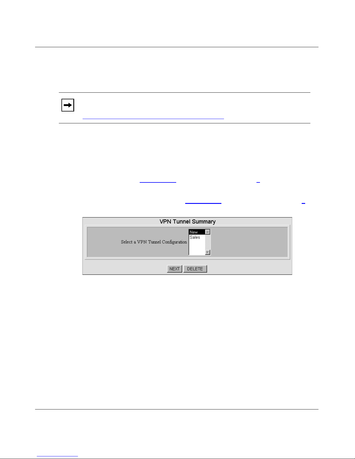
Installation and Reference for the BayStack 820 ISDN Router
Configuring a VPN Tunnel
To set up access to and from a remote site, be sure to configure both ends of the
VPN tunnel—both the remote router and the local router—appropriately.
Note: When communicating with a re mote office, the private IP addresses
must be different on both ends of the connection. For details, refer to
“Configuring Advanced IP Settings” on page 9-1
To configure a VPN tunnel:
1. Choose Configuration > WAN Interfaces > VPN Tunnel.
2. Do one of the following:
• If you configured at least o ne VPN tunnel , th e VPN Tunnel Summary
dialog box (Figure 4-7)
• If you are configuring the first VPN Tunnel, the VPN Tunnel
Configuration dialog box (Figure 4-8) opens. Proceed with Step 4.
opens. Proceed with Step 3.
.
Figure 4-7. VPN Tunnel Summary Dialog Box
4-12 206901-A
Page 87

Configuring Remote Office Access
Do one of the following:
3.
• To create a new VPN tunnel, select New from the list and then click
NEXT.
• To edit an existing VPN t unnel, select it in the list and then click
NEXT.
The VPN Tunnel Configuration dialog box (Figure 4-8)
Figure 4-8. VPN Tunnel Configuration Dialog Box
Use the information in Table 4-4 to configure the VPN settings and then
4.
opens.
click APPLY.
206901-A 4-13
Page 88

Installation and Reference for the BayStack 820 ISDN Router
Table 4-4. VPN Tunnel Configuration Fields
Field Description
Tunnel Name Enter a name for this VPN tunnel.
Call Direction Select the direction of the call in the tunnel. Select from:
• Incoming Only – Select this direction if the remote site will always initiate the
connection to the router.
• Outgoing Only – Select this direction if the router will always initiate the
connection to the remote site.
• Both – Select this direction if both the remote site and the router will initiate the
connection.The default setting is Both.
Remote IP Address Enter the IP address of a destination workstation on a network reachable through
this connection.
This field is displayed when you set Call Direction to Outgoing Only or Both.
My System Name Enter the n ame that the re mo te syste m us es to recog nize your n etwork. This field is
case sensitive, so nortel is not the same as Nortel or NORTEL.
My System Password Enter the password the remote system uses to authenticate your system. If the
remote site does n ot require t unnel auth enticati on, leave this fiel d blank. This field is
case sensitive, so nortel is not the same as Nortel or NORTEL.
NOTE: The remote site must be configured with your System Name (and System
Password, if used).
Remote System
Name
Remote System
Password
Enter the system name of the remote network that is dialing in. This field is case
sensitive, so nortel is not the same as Nortel or NORTEL.
Enter the password the router will use to authenticate the remote system. If your
system does require tunnel authentication, leave this field blank. This field is case
sensitive, so nortel is not the same as Nortel or NORTEL.
4-14 206901-A
Page 89
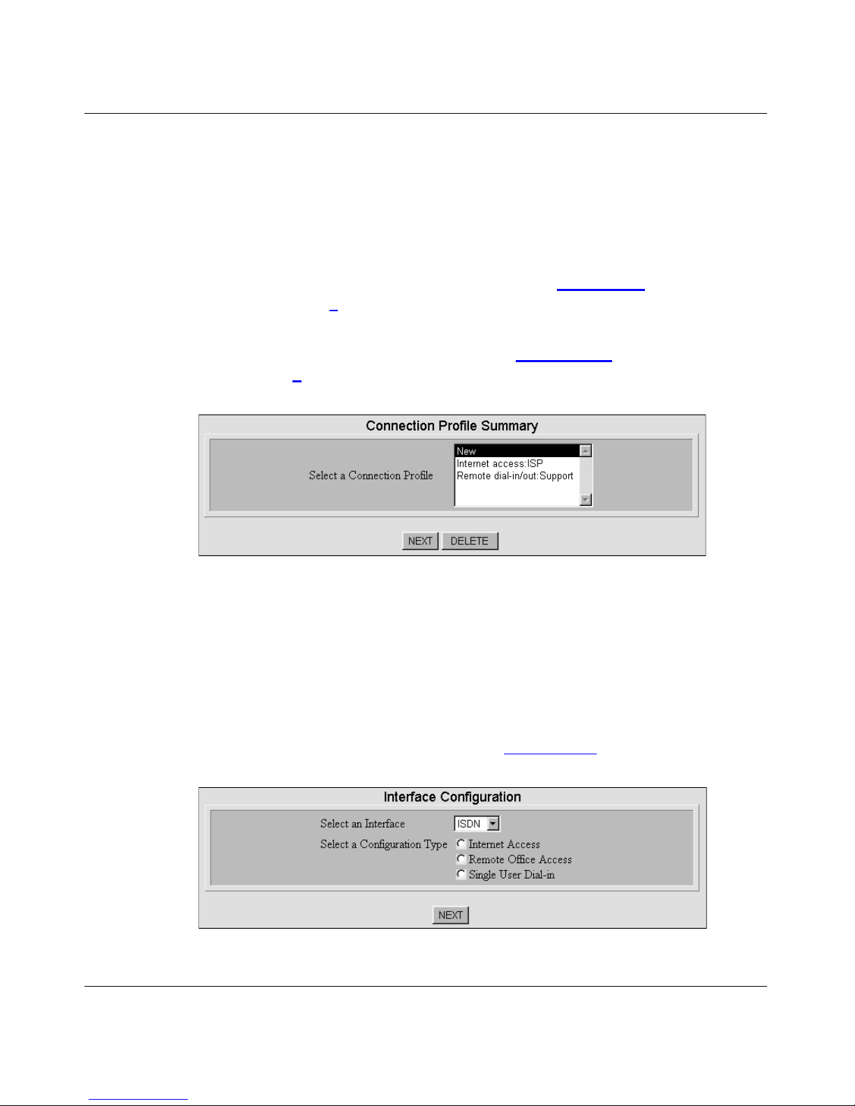
Configuring a VPN Connection Profile
To create a VPN connection profile:
1. Select Configuration > Connection Profiles and then do one of the
following:
• If you have configured at least one Connection Profile, the
Connection Profile Summary dialog box (Figure 4-9)
with Step 2
• If you are configuring a Connection Profile for the first time, the
Interface Configurati on dialog box (Figure 4-10) opens. Proceed with
Step 3
.
.
Configuring Remote Office Access
opens. Proceed
Figure 4-9. Connection Profile Summary Dialog Box
Do one of the following:
2.
• To create a new Connection Profile, se le ct New from the list and then
click NEXT.
• To edit an existing Connection Profile, select it in the list and th en
click NEXT.
The Interface Configuration dialog box (Figure 4-10)
Figure 4-10. Interface Configuration Dialog Box
opens.
206901-A 4-15
Page 90

Installation and Reference for the BayStack 820 ISDN Router
3. Select VPN as the interface.
4. Select Remote Office Access as the configuration type and then click
NEXT.
The configuration type options displayed in this dialog box depend upon the
selections you made in the BayStack 820 ISDN Router Manager
Configuration dial og box. For details, refer to “
820 ISDN Router Manager Interface” on page 3-3.
The Connection Profi le Co nfi gur at io n, Remot e Office Access by VPN dialog
box (Figure 4-11)
opens.
Customiz ing the BayS tack
Figure 4-11. Connection Profile Configuration, Remote Office Access by
VPN Dialog Box
Use the information in Table 4-5 to configure the VPN settings and then
5.
do one of the following :
• If you set the Call Direction to Incoming, click APPLY.
• If you set the Call Direction to Outgoing or Both, click APPLY and
TEST or click ADVANCED for more options.
You must still click APPLY and TEST even if the other end of the connection
has not been configured. When you click APPLY and TEST, the BayStack
820 ISDN R outer attemp ts to place a call to the remote site and lo g in.
4-16 206901-A
Page 91

Configuring Remote Office Access
Monitor the Message Window for any progress messages. If the test is
successful, the router disconnects from the remote site. If the test is not
successful, you can make changes to the configuration based on progress
messages that appear in the Message Window, and then try again.
Table 4-5. Connection Profile Configuration, Remote Office Access by VPN Fields
Field Description
Profile Name Enter a name to identify this VPN profile.
Call Direction Select a call direction. Choose from:
• Incoming – Select this direction if the remote site will dial in to the router.
• Outgoing – Select this direction if the router will dial out to the remote site.
• Both – Select this direction if the remote site will dial in and the router will dial
out. The default direction is Both.
NOTE: If you set the Call Directi on to Inc om ing Only, the My System Name and My
System Password fields are not displayed. If you set Call Direction to Outgoing
Only, the Remote System Name and Remote System Password fields are not
displayed. If only incoming calls are allowed with this profile, the APPLY and TEST
button is not displayed.
My System Name Enter the name that the remo te sy stem uses to recog nize your n etwo rk. Thi s fie ld is
case sensitive, so nortel is not the same as Nortel or NORTEL.
My System
Password
Remote System
Name
Remote System
Password
VPN Tunnel Select the VPN tunnel for this profile. VPN tunnels are configured separately. For
Enter the password the remote system will use to authenticate your system. This
field is case sensitive, so nortel is not the same as Nortel or NORTEL.
NOTE: The VPN connection profile at the remote site must be configured with your
System Name and System Password.
Enter the system name of the remote network that is dialing in. This field is case
sensitive, so nortel is not the same as Nortel or NORTEL.
Enter the password the route r wi ll u se to auth ent ic ate th e rem ote sy ste m. This fie ld
is case sensitive, so nortel is not the same as Nortel or NORTEL.
details, refer to “Config uring a VPN Tunnel” on page 4-12
.
Configuring Advanced VPN Connection Profile Options
The IPX options are displayed in this dialog box only if you selected the Share
NetWare (IPX) Resource check box on the BayStack 820 ISDN Router Manager
Configuration dial og box. For details, refer to “
ISDN Router Manager Interface” on page 3-3.
Customizing the BayStack 820
206901-A 4-17
Page 92

Installation and Reference for the BayStack 820 ISDN Router
To configure advanced VPN connection profile options:
1. In the Connection Profile Configuration, Remote Office Access by VPN
dialog box (Figure 4-11)
, click Advanced.
The Connection Profil e Configuration, Remote Office Access by VPN
(advanced) dialog box (Figure 4-12)
opens.
Figure 4-12. Connection Profile Configuration, Remote Office Access by
VPN (Advanced) Dialog Box
Use the information in Table 4-6 to configure advanced VPN profile
2.
settings and then click OK.
4-18 206901-A
Page 93

Configuring Remote Office Access
Table 4-6. Connection Profile Configuration, Remote Office Access by VPN
(Advanced) Fields
Field Description
Enable IP Select whether to enable IP routing over a connection using this profile. When you
enable IP routing, th e router routes IP data packets to the ap propriate server or h ost
according to entries in the IP routing table.
Remote IP Address Enter the IP address of a destination workstation on a network reachable through
this connection.
Remote IP Netmask Enter the IP subnet mask of the remote IP address.
Enable IPX Select whether to enable IPX routing over a conne ction using this profile. When you
enable IPX routing, the router routes IPX data packets to the appropriate server or
host according to entries in the IPX routing table.
This field is displayed if you sele cted Share NetWare (IPX) Resource in the
BayStack 820 ISDN Router Manager customization dialog box.
IPX RIP/SAP Select whether to enable IPX Routing Information Protocol (RIP) and Service
Advertising Protocol (SAP). Whe n you enabl e IPX RIP/SAP, the router receives RIP
and SAP broadcast data from other routers, and broadcasts the routing table and
routing table updates as necessary.
This field is displayed if you sele cted Share NetWare (IPX) Resource in the
BayStack 820 ISDN Router Manager customization dialog box.
Set as IPX Default
Route
Remote IPX Network
Number
Enable Bridging Select whether to enable bridging to non-IP or non-IPX protocols, for example,
Select whether to se t this profile as the default route. When you enable this profile
as the default route, the router uses this connection if no other route for an IPX
packet is found in the routing table.
This field is displayed if you sele cted Share NetWare (IPX) Resource in the
BayStack 820 ISDN Router Manager customization dialog box.
Enter the IPX network number of a network reac hable through this connection. If
you enabled IPX as the default route for this connection, an entry in this field is not
required.
This field is displayed if you sele cted Share NetWare (IPX) Resource in the
BayStack 820 ISDN Router Manager customization dialog box.
SNA, Appletalk, and NetBEUI. You may also have to enable bridging if the remote
connection supports only bridging.
NOTE: If you enabled IP routing or IPX routing, routing takes precedence. For
example, if you enabled both bridging and IP routing, IP data is routed, and all
non-IP data is bridged.
206901-A 4-19
Page 94

Installation and Reference for the BayStack 820 ISDN Router
Table 4-6. Connection Profile Configuration, Remote Office Access by VPN
(Advanced) Fields
Field Description
Enable Encryption Select whether to enable DES encryption. When you enable encryption the router
encrypts all data before it is sent out to the WAN, and decrypts data when it is
received from over the WAN.
This field is displayed if the workstation is connected to the router over a local LAN
and encryption is enabled.
DES Encryption key Enter the DES encryption key to be used by other systems to establish a
connection with your system. You need to enter a must be a hexadecimal number
with either 40 or 56 bits (10 or 14 digits).
This field is displayed when Enable Encryption is set to Yes.
(continued)
Confirm Encryption
key
Reenter the DES encryption key to confirm that you entered it correctly.
This field is displayed when Enable Encryption is set to Yes.
4-20 206901-A
Page 95

Chapter 5
Configuring Dial-In User Access
This chapter describ es how to configure dia l-in access use r connection prof iles for
remote access.
Standalone remote works tations use a dial-in user connectio n profile to connect to
the router over a switched connection such as over an ISDN line. The connected
workstation effectively becomes a LAN node for the duration of the connection
and its ARP information is proxied by the router.
When a switched call is answered, the router searches the local profile database
for a match with the received name and password. If an appropriate profile is not
found, the call is rejected. If a profile is found, other information in the entry is
used to configure the connection.
To allow dial-in access from remote users, you must select Dial-in Access for
Off-Site Users in the BayStack 820 ISDN Router Manager customization dialog
box. If you want to configure NetWare resources for remote access connections,
select Share NetWare (IPX) Resource. For details, refer to “
BayStack 820 ISDN Router Manager Interface” on page 3-3.
Before you configure a dial-in user connection profile, you need to configure the
ISDN connection. For details, refe r to “
page 3-9.
Configuring ISDN Port Settings” on
Customizing the
206901-A 5-1
Page 96

Installation and Reference for the BayStack 820 ISDN Router
Configuring a Dial-I n User Connection Profile
To configure a dial-in user connection profile:
1. Choose Configuration > Connection Profiles and then do one of the
following:
• If you configured at least one connection profile, the Connection
Profile Summary dialog box (Figure 5-1)
• If you are configuring a connection profile for the first time, the
Interface Configuration dialog box (Figure 5-2)
Step 3
.
opens. Proceed with Step 2.
opens. Proceed with
The Connection Profil e Summary dialog box (Figure 5-1)
Figure 5-1. Connection Profile Summary Dialog Box
Do one of the following:
2.
opens.
• To create a new connection profile, select New from the list and then
click NEXT.
• To edit an existing connection profile, select it in the list and then
click NEXT.
The Interface Configuration dialog box (Figure 5-2)
opens.
5-2 206901-A
Page 97

Configuring Dial-In User Access
Figure 5-2. Interface Configuration Dialog Box
Select ISDN as the interface.
3.
4. Select Single User Dial-in as the configuration type and then click NEXT.
The configuration type options displayed in this dialog box depend upon the
selections you made in the BayStack 820 ISDN Router Manager
Configuration dial og box. For details, refer to “
Customiz ing the BayS tack
820 ISDN Router Manager Interface” on page 3-3.
The Connection Profil e Configuration, Single User Dial-in by ISDN dialog
box (Figure 5-3)
Figure 5-3. Connection Profile Configuration, Single User Dial-in by
5.
Use the information in Table 5-1 to configure the dial-in access settings
opens.
ISDN Dialog Box
and then click APPLY (or click ADVANCED for more options).
206901-A 5-3
Page 98

Installation and Reference for the BayStack 820 ISDN Router
Table 5-1. Connection Profile Configuration, Single User Dial-in by ISDN Fields
Field Description
Profile Name Enter a name to identify this profile.
Call Back Select whether to en abl e the call back security featu re. When you enable call back,
the router answe r s an i nco ming call, authenticates the di al -in us er’s user name and
password, disconnects the call, and then dials the remote user’s call back number
to reconnect.
Call Back Phone
Number
Incoming
Authentication
User Name Enter the remote user’s user name to be used for auth ent ic ati on. Th e use r nam e is
User Password Ente r the remote user’s passwo rd to be used for auth enticatio n. The user pass word
Enter the remote user’s call back phone number.
This field is displayed when you set Call Back to Yes.
Displays the method used for authentication. The router first uses CHAP to
authenticate the incoming call. If CHAP authentication fails, then PAP is used.
case-sensitiv e , so Nortel is not the same as nortel or NORTEL.
is case-sensitive, so Nortel is not the same as nortel or NORTEL.
Configuring Advanced Options for a Dial-in User Connection Profile
To configure advanced options for a dial-in user connection profile:
1. In the Connection Profile Configuration, Single User Dial-in by ISDN
dialog box (Figure 5-3)
The Connection Profil e Configuration, Single User Dial-in by ISDN
(advanced) dialog box (Figure 5-4) opens.
, click Advanced.
Figure 5-4. Connection Profile Configuration, Single User Dial-in by
5-4 206901-A
ISDN (Advanced) Dialog Box
Page 99

Configuring Dial-In User Access
Use the information in Table 5-2 to configure the advanced dial-in
2.
settings and then click OK.
Table 5-2. Connection Profile Configuration, Single User Dial-in by ISDN (Advanced)
Fields
Field Description
Caller ID Authen Select whether to enable caller ID authentication for this profile. When caller ID
authentication is ena bled, the route r verifies the incoming cal ler ID before acce pting
the call. This s erv ic e ma y requ ire a special service from your ISDN service provider.
Caller ID Number Enter the caller ID phone number to authenticate.
This field is displayed when you set Caller ID Authen. to Yes.
ST AC Compression Select whether to use ST AC com pression. STAC compression allows outgoing data
to be compressed to achieve higher throughput, and decompressed incoming data
to be recognized. The ability to use compression depends on the capabilities of
your ISP.
Idle Timeout Enter the number of seconds of inactivity for the connection before the router
disconnects the call. You can set the idle timeout from 0 to 3600 seconds. The
default setting is 120 seconds. If you set the timeout to 0, the connection never
times out.
Enable IP Select whether to enable IP routing over a connection using this profile. When you
enable IP routing, th e router routes IP data packets to the ap propriate server or h ost
according to entries in the IP routing table.
Enable IPX Select whether to enable IPX routing over a conne ction using this profile. When you
enable IPX routing, the router routes IPX data packets to the appropriate server or
host according to entries in the IPX routing table.
This field is displayed if you sele cted Share NetWare (IPX) Resource in the
BayStack 820 ISDN Router Manager customization dialog box.
Remote IPX Network
Number
Enter the IPX network number of a network reac hable through this connection.
This field is displayed when you set Enable IPX to Yes.
206901-A 5-5
Page 100

Installation and Reference for the BayStack 820 ISDN Router
Configuring Multilink Options for Dial-In Access
Configure Multilink options if you require advanced conf iguration for the
operation on the ISDN line and its loadsharing capabilities.
Note: The use of multiple B channels depends on the device and capabilities
of the dial-in user’s ISDN subscription. Using an additional B channel may
mean additional cost . If the same phone number is used for both channels,
make sure that the I SDN subscription specifies a hunt group f or the two ISDN
B channels.
To configure Multilink options for dial-in access:
1. In the Connection Profile Configuration, Single User Dial-in by ISDN
Screen (Advanced) dialog box (Figure 5-4)
The Connection Profil e Configuration, Single User Dial-in by ISDN
(Multilink) dialog box (Figure 5-5)
opens.
, click Multilink.
Figure 5-5. Connection Profile Configuration, Single User Dial-in by
5-6 206901-A
ISDN (Multilink) Dialog Box
 Loading...