

Page 1

Part No. 206375-A
June 1999
4401 Great America Parkway
Santa Clara, CA 95054
Installation and Reference for
the BayStack 70 Series 10/100
Ethernet Switches
*206375-A*
Page 2

Copyright © 1999 Nortel Networks.
All rights reserved. Printed in th e U S A . June 1999.
The information in this document is subject to change without notice. The statements, configurations, technical data,
and recomm endation s in this docum ent are believed to be accurate and reliable, but are presented without express or
implied warra nty. Users must take full responsibility for their applications of any prod ucts specified in this docume nt.
The information in this document is proprietary to Nortel Ne tworks NA Inc.
Trademarks
NORTEL NETWORKS is a trademark of Nortel Networks Corpora ti on.
Bay Netwo rks is a registered trademark and BayStack and the Nortel Networks logo are trademarks of N ortel
Networks NA Inc.
Microsoft is a registered trademark of Microsoft Corpor ation.
All other trademarks and registered trademarks are the property of their re spective owners.
Notice
Note: This equipment has been tested and found to comply with the limits for a Class A digital device, pursuant to
Part 15 of the FCC rule s. These limits are designed to provide reasonable protection against harmful interference
when the equipment is o perated in a commercial environment. Thi s equipment generates, uses, and can radiate radio
frequency energy. If it is not insta lled and used in accorda nce with the instructi on manual, it ma y cause harmful
interference to radio communications. Operation of this equipment in a residential area is likely to cause harmful
interference, in which case users will be required to take whatever measures may be necessary to correct the
interference at their own expense.
EN 55 02 2 Stateme n t
This is to certify that the Nortel Networks BayStack 70 Series 10/100 Ethernet Switches are shielded against the
generation of radi o interference in accordance with the application of Council Directive 89/336/EEC, Article 4a.
Conformity is declared by the applicati on of EN 55 022 Class A (CI SPR 22).
Warning: This is a Class A product. In a domestic environment, this product may cause radio in terference, in which
case, the user may be r equired to take appr opriate measures.
EC Declaration of Conformity
These products confor m to the provisions of Council Direct ive 89/336/EEC and 73/23/EEC.
The Declaration of Conf ormity is a vailable on the Nortel Networks Wo rld Wide Web site at
http:/ /libra2.corpwe st.baynetworks.com/cgi-bin/ndCGI.exe/ D ocView/.
Voluntary Control Council for Interference (VCCI) Statement
ii
206375-A
Page 3

Voluntary Control Council for Interference (VCCI) Statement
This is a Class A product based on the standard of the Voluntary Control Council for Interference by Information
Technology Equipmen t (V CCI). If this equipment is used in a domestic environment, radio disturbance may arise.
When such trouble occurs, the user may be required to take corrective actions.
Canadian Department of Communications Radio Interference Regulations
This digit al appa ra tus (BaySta ck 70 Ser i es 10/10 0 Ethe rn et Swi tches ) do not ex ceed th e Clas s A limi ts for radi o-noi se
emissions from digital apparatus as set out in the Radio Interference Regulations of the Canadian Department of
Communica tions.
Règlement sur le brouillage radioélectrique du ministère des Communications
Cet appareil numérique (BayStack 70 Series 10/100 Ethernet Switches) respecte les limites de bruits radioélectriques
visant le s ap parei ls numér iques de cl ass e A pre scrit es dans le Règ le ment sur le broui ll age ra dio él ectr iqu e du min istè re
des Communications du Canada.
Electrom agne ti c I n ter fer ence (EM I ) Stateme n t
Wichtige Sicherheits hinweis e
1. Bitte les en Sie diese Hinw eise sorgfaltig durch.
2. Heben Sie diese Anleitung fur den spateren Gebrauch auf.
3. Vor jedem Reinigen ist das Gerat vom Stromnetz zu trennen. Verwenden Si e keine Flussigoder A erosolreiniger.
Am besten eignet sich ein angefeuchtetes Tuch zur Reinigung.
4. Um eine Beschadigung des Gerates zu vermeiden sollten Si e nur Zubehorteile v erwenden, die vom Hersteller
zugelassen sind.
5. D a s G e ra t ist vor Feuch tigke it zu sc hutze n .
6. Bei der Aufstellung de s G erates ist auf sicheren Stand zu achten. Ein Kippen oder Fallen ko nnte Verletzungen
hervorrufen. Ver w enden Sie nur sichere Standorte und beachten Sie die Aufste llhinweise des Herstellers.
7. Die Beluftungsoffnungen dienen der Luftzirkulation die das Gerat vor Uberhitzung schutzt. Sorgen Sie dafur,
daB diese Offnungen nicht abgedeckt wer den.
8. Beachten Si e beim AnschluB an das Stromnetz die AnschluBwerte.
9. Die Netzanschlusteckdose muB aus Grunden der elektrischen Sicherheit einen Schutzleiterkontakt haben.
10. Verlegen Sie die Netzan schluBleitung so, daB niemand daruber fallen kann. Es sollte auch nichts auf d er Leitung
abgestellt werden.
11. Alle Hinweise und Warnungen, die sich am Geraten befinden sind zu beachten.
206375-A
iii
Page 4

12. Wird das Gerat uber einen langeren Zeitraum nicht benutzt, sollten Sie es vom Stromnetztrennen. Somit wird im
Falle ei ner Uberspannung eine Beschadigung verm ieden.
13. Durch die Luf tungso f f nungen dur fe n niem a ls Ge gen st ande od er Flu ssi gkei t en in d as Gera t gel angen. Di es ko nnte
einen Brand bzw. elektrische n Schlag auslosen.
14. Offnen sie niemals das Gerat. Das Gerat darf aus Grunden der elektrischen Sicherheit nur von authorisiertem
Servicepersonal geoffnet werden.
15. Wenn folgende Situ ationen auftrete n ist das Gerat vom Stromnetz zu trennen und von einer qua lifizierten
Servicestelle zu uberprufen:
a Netzkabel oder Netzstecker sind beschadigt.
b Flussigkeit is t in das Gerat eingedrungen.
c Das Gerat w ar Feuchtigkeit ausgesetzt.
d Wenn das Gerat nicht der Bedienungsanleitung entsprechend funktioniert oder Sie mit Hilfedieser Anleitung
keine Verbesserung erzielen.
e Das Ger at ist gefallen und /oder das Gehause ist beschadigt.
f Wenn das Gerat deutliche Anzeichen eines Defe ktes aufweist.
16. Bei Reparat uren durfen nur Orgi nalersatzteile bzw. den Orginalteilen entsprechende Teile verwendet wer den.
Der Einsat z von ungeeigneten Ersatzteile n kann eine weitere Beschadigung hervorrufen.
17. Wenden Sie sich mit al len Fragen die Service und Repartur betreffen an Ihren Servicepartner. Somit stellen Sie
die Betriebssicherheit des Gerates sicher.
18. Zum Netzan schluB dieses Gerates ist eine geprufte Lei tung zu verwenden. Fur einen Nennstrom bis 6A und
einem Gerategewicht gr oBer 3kg ist eine Leitung nicht leichter als H05VV-F, 3G, 0.75mm 2 einzusetzen. Der
arbeitsplatzbezogene Schalldruckpegel nach D IN 45 635 Teil 1000 betragt 70dB(A) oder weniger.
Restricted Rights Legend
Use, duplication, or disclosure by the United States Government is subject to restrictions as set forth in sub p aragraph
(c)(1)(ii) of th e Rights in Technical Data and Computer Software clause at DFARS 252.227-7013.
Notwithstanding any other license agreement that may pertain to, or accompany the delivery of, this computer
software, the rights of the Unite d States Governm ent regarding i ts use, reproduction, and disclosure are as set forth in
the Commer cial Computer Software-Restricted Rights clause at FAR 52.227-19.
Statement of Conditions
In the interest of improving internal design, operational function, and/or rel iability, Nortel Networks NA Inc . reserves
the right to make ch anges to the products described in this docum ent without notice.
Nortel Networks NA Inc. doe s not assume an y liability that may occur due to the use or application of the product(s)
or circui t layout(s) described herein.
Portions of the code in this software product are Copyri ght © 1988, Regents of the Uni versity of California. All rights
reserved. Redistribu tion and use in source and binary forms of such portions are permitted, provided that the above
copyrig ht notic e an d th is para grap h ar e dup lica te d in al l such f or ms and th at a n y docum en tati on, adv e rtis in g mat er ials ,
and other mat erial s r elat ed to such di st rib ut ion and use ac kno wled ge t ha t such p or tions of t he soft war e we re d ev el op ed
by the University of Ca lifornia, Berkeley. The name of the University may not be used to end o rse or promote products
derived from such portions of the software without specific prior written permission.
SUCH PORTI ONS OF THE SOFTWARE ARE PROVIDED “AS IS” AND WITHOUT ANY EXPRESS OR
IMPLIED WARRANTIES, INCLUDING, WITHOUT LIMITATION, THE IMPLIED WARRANTIES OF
MERCHANTABILITY AND FITNESS FOR A PARTICULAR PURPOSE.
iv
206375-A
Page 5

Nortel Networks NA Inc. Software License Agreement
NOTICE: Pl ease carefully read this license agreement before copying or using the accom panying software or
installing the hardwa re unit with pre- enabled software (each of which is referred to as “Software” in t his Agreement).
BY COPYING OR USING THE SOFTWARE, YOU ACCEPT ALL OF THE TERMS AND CONDITIONS OF
THIS LICENSE AGREEME N T. THE TERMS EXPRESSED IN THIS AGREEMENT ARE THE ONLY TERMS
UNDER WHICH NORTEL NETW ORKS WI LL PERM IT YOU TO USE THE SOFTWARE. If you do not acc ept
these terms and conditions, return the product, unused and in the original shipping container, within 30 days of
purchase to obtain a cr edit for the f ull purchase price.
1. License Grant. Nortel Networks NA Inc. (“Nortel Networks”) grants t he end user of the Software (“Licensee”) a
personal , none xcl us iv e , non trans fe ra ble li cen se: a) t o use th e Sof tware eit he r on a singl e compu te r or , if appli ca bl e, on
a single author ized device identified by host ID, for which it was originally acquired; b) to copy the Software solely
for backup purposes in support of authorized use of the Software; and c) to use and copy the associated user manual
solely in support of authorized use of the Software by License e. This license appli es to the Soft w are only and does not
extend to Nortel Networks Agent softwa re or other Nortel Networks software products. Nortel Netwo rk s Agent
software or other N ortel Networks software products are licens ed for use under the terms of the applicable Nortel
Networks NA Inc. Software License Agreement that accompa nies such software and upon paym ent by the end user of
the applicable license fees for such software.
2. Restri ctions on use; reservation of rights. The Soft ware and user manuals are protected under copyright laws.
Nortel Networks and/or its licensors retain all title and ownership in both the Software and user manuals, including
any revisions made by Nortel Networks or its li censors. The copyr ight notice must be reproduced and included wit h
any copy of an y por tion of the Soft war e or user man uals. Lic ens ee may not modi fy, translate , dec ompi le, di sa ss emble,
use for any competitive analysis, reverse engineer, distribute, or create derivative works from the Software or user
manuals or any copy, in whole o r in part. Except as expressly p rovided in this Agreement, Licensee may not copy or
transfer the Software or user manuals, in whole or in part. The Software and user manuals embody No rtel Networks’
and its licensors’ confide ntial and proprietary intellectual property. Licensee shall not sublicense , assign, or oth erwise
disclos e to any third party the Software, or any information about the operation, design, performance, or
implementation of the Software and user manuals that is confidential to Nortel Networks and its licensors; however,
Licensee may grant permission t o its consultants, subcontrac tors, and agent s to use the Software a t Licensee’s facility,
provided they have agreed to use the Software only in accordance with th e terms of this license.
3. Limited warranty . N ortel Networks warrants each item of Software, as delivered by Nortel Networks and properly
installed and operated on Nortel Networks hardware or other equipment it is originally licens ed for, to funct ion
substant ially as described in its accompanying user manual during its warranty period, which begins on the date
Softwar e is fir st shippe d to Li censee . I f an y item of Soft wa re f ail s to so functi on duri ng its warr an ty peri od, as th e sole
remedy Nor tel Net wor ks wil l at it s discr et ion provi de a sui tabl e f ix, pat ch , or wo rkaro und fo r the prob lem th at may be
included in a future Software release. Nortel Networks further warra nts to Licensee that t he media on which the
Software is provided will be free from defects in materials and workmanship under normal use for a period of 90 days
from the date Software is first shipped to Licensee. Nortel Networks will replace defective media at no charge if it is
returned to Nortel Networks during the warranty period along with proof of the date of shipment. This warran ty does
not apply i f the media has been damaged as a result of ac cident, misuse, or abuse. The Licensee as sumes all
resp on s i b il ity for se le ct io n of the Softwar e to ac hi eve Li ce nsee ’s inten de d res ul ts and for the inst al lation , use , and
result s obtained from the Softw are. Nortel Networ ks does not warrant a) th at the functions contai ned in the software
will meet the Licensee’s requirements, b) that the Software will operate in the hardware or software combinations that
the Licensee may select, c) that the operation of the Software will be uninterrupted or error free, or d) that all defects
in the ope rat ion of th e Sof tw are will be c orr ec ted. Nort el Net wor ks is n ot o bli g at ed to re me dy an y Sof tw ar e de fect tha t
cannot be reproduced with the latest Software release. These warranties do not apply to the Software if it has been (i)
altered, except by Nortel Netw orks or in accordance wi th its instructions; (ii) used in conjunction with another
vendor’s product, resulting in the defect; or (ii i) damaged by improper environment, abuse, misuse, accident, or
negligence. THE FOREGOING WARRANTIES AND LIMITATI ONS ARE EXCLUSIVE REMEDIES AND ARE
IN LIEU OF ALL OTHER WARRANTIES EXPRESS OR IMPLIED, I NCLUDING WITHOUT LIMITATION ANY
WARRANTY OF MERCHANT ABILI TY OR FITNESS FOR A PARTICULAR PURPOSE. Licensee is responsible
for the security of its ow n data and information and for mai n taining adequate procedures apart from the Software to
reconstruct lost or altered files, data, or program s
.
206375-A
v
Page 6

4. Limitation of liability. IN NO EVENT WILL NORTEL NETWORKS OR ITS LI CENSORS BE LIABLE FOR
ANY COST OF SUBSTITUTE PR OCUREMENT; SPECIAL, INDIRECT, INCIDENTAL, OR CONSEQUENTIAL
DAMAGES; OR ANY DAMAGES RESULTING FR OM INACCURATE OR LOST DAT A OR LOSS OF USE OR
PROFITS ARISI NG OUT OF OR IN CONNECTION WITH THE PERFORMANCE OF THE SOFTWARE, EVEN
IF NOR TEL NETWORKS HAS BEEN ADVISED OF THE POSSIBILITY OF SUCH DAMAGES. IN NO EVENT
SHALL THE LIABILITY OF NORTEL NETWORKS RELATING TO THE SOFTWARE OR THIS AGREEMENT
EXCEED THE PRICE PAID TO NORTEL NETWORKS FOR THE SOFTWARE LICENSE.
5. Government Licensees. This pro visi on a pplie s t o a ll Sof tw ar e and do cume nta ti on acq ui red dire ctl y o r indi r ectl y b y
or on behalf of the United States Go vernment. The Software and documentation are commerci al products, licensed on
the open market at market pri ces, and were developed enti rely at pri vate expense and without the use of any U .S.
Gove rnment funds. The license to the U.S. Gov ernment is granted only with restri cted rights, and use, duplication, or
disclosure by the U.S. Gov ernment is subject to the restrictions set forth in subparagraph (c)(1) of the Commercial
Computer Software––Restricted Rights clause of FAR 52.227-19 and the li m itations set out in this license for civilian
agencies, and subparagraph (c)(1)(ii ) of the Rights in Technical Data and Co mputer Software clause of DFARS
252.227-7013, for agencies of the Departm ent of Defense or their successors, whichever is applica ble.
6. Use of Software in the European Community. This prov is ion appl i es to all Sof tw ar e ac q uired for use wi th in the
European Comm unity. If Licensee uses the Softw are within a country in the European Community, the Softw are
Directive enacted by the Council of European Communities Directive dated 14 May, 1991, will apply to the
examination of the Software to facilitate interoperability. Licensee agrees to notify Nortel Networks of any such
intended exami nation of the Software and may proc ure support and assis tance from Nortel Ne tworks.
7. Term and termination. Thi s license is eff ective until terminated; however, all of the restrictions with respect to
Nortel Networ ks’ copyright in the Softwar e and user manuals will cease being effective at the date of expiration of the
Nortel Networks copyright; those restrictio ns relating to use and di sclosure of Nortel Netw orks’ confidential
information shall continue in effect. Lic ensee may terminat e this license at any time. The license will automatically
terminate if Licensee fails to comply with any of the terms and conditions of the license. Upon termination for any
reason, Licensee w ill immediately destroy or return to Nort el Networ ks the Software, user manuals , and all copies.
Nortel Networks is not liabl e to Licensee for damages in any form solely by reason of the term ination of this lic ense.
8. Export and Re-export. Licensee agrees not to export, di rectly or indirectly, the Software or related technical data
or information without first obtaining any required export licenses or other governm ental approvals. Without limiting
the foregoing, Licensee, on beha lf of itself and its subsidiaries and affiliates, agrees that it will not, w ithout first
obtaini ng all export licenses and approval s required by the U.S. G overnment: (i) export, re-export, tra nsfer, or divert
any such Software or technical data, or any direct product thereof, to any country to which such exports or re-exports
are restricted or embargoed under United States export control laws and regulations, or to any national or resident of
such restricted or embar goed countries; or (ii) provide the Software o r related technica l data or information to any
militar y end user or for any military end use, includ ing the design, development, or produc tion of any chemical,
nuclear, or biologica l w eapons.
9. General. If any provision of this Agreement is held to be invalid or unenforceable by a court of competent
jurisdiction, the remainder of the provisions of this Agreement shall remain in full force and effect. This Agreement
will be governed by the laws of the st ate of California.
Should you have any questi ons concerning this Agreement, contact Nortel N etworks, 4401 Great Americ a Parkway,
P.O. Box 58185, Sant a Clara, California 95054- 8185.
LICENSEE ACKNOWLEDGES THAT LICENSEE HAS READ THIS AGREEMENT, UNDERSTANDS IT, AND
AGREES TO BE BOUND BY ITS TERMS AND CONDITIONS. LICENSEE FURTHER AGREES THAT THIS
AGREEMENT IS THE ENTIRE AND EXCLUSIVE AGREEMENT BETWEEN NORTEL NETWORKS AND
LICENSEE, WHICH SUPERSEDES ALL PRIOR ORAL AND WRITTEN AGREEMENTS AND
COMMUNICATIONS BETWEEN THE PARTI ES PERTAINING TO THE SUBJECT MATTER OF THIS
AGREEMENT. NO DIFFERENT OR ADDITIONAL TERMS WILL BE ENFORCEABLE A GAINST NORTEL
NETWORKS UNLESS NORTEL NETWORKS GIVES ITS EXPRESS WRITTEN CONSENT, INCLUDING AN
EXPRESS WAIVER OF THE TERMS OF THIS AGREEMENT.
vi
206375-A
Page 7

Contents
Preface
Purpose ............................................................................................................................ xi
Audience ...........................................................................................................................xii
Hard-Copy Technical Manuals ................ .. ....... .......... ....... .. .......... ....... .. ....... .......... ....... .. .xii
How to Get Help ..............................................................................................................xiii
Chapter 1
Introduction
BayStack 70 Series 10/100 Ether net Switch Overview ..................................................1-1
Physical Description .......................................................................................................1-2
F r o n t Panel . .............. ................................. ..................................................... ..........1-2
RJ-45 10BASE- T /1 0 0 BASE-TX Ethernet Ports ......................................... ........1-4
MDI/MDI-X Bu tton ......... ................................. ...................................................1-4
LEDs .................................................................................................................. 1-5
Rear Panel ...............................................................................................................1-6
Rear Panel of the BayStack 70-8T 10/100 Ethernet Switch and
BayStack 70-16T 10/100 Ethernet Switch .......................................................1-6
Rear Panel of the BayStack 70-24T 10/100 Ethernet Switch ............................1-7
DC Power Adapter ...................... ................................. .................................. ..........1-8
Cabl e Holde r ....................................................... ................................. ....................1-8
Cooling Fans ............................................................................................................ 1-9
Features ..........................................................................................................................1-9
206375-A
vii
Page 8

Chapter 2
Network Configuration
Benefits of Using Switching Technology ....................................... ....... ....... .. .......... ....... .2-1
Types of Ethernet Switches ......................................................................................2-2
Desktop Switching ............... ................................. .................................................... ......2-3
Segment Switching .........................................................................................................2-4
Extending a Network ...................................................................................................... 2-6
Bridging from 10BASE-T to 100BASE-TX Networ ks ...................................................... 2-7
Power Workgroups .........................................................................................................2-8
Chapter 3
Installation
Package Contents .......................................................................................................... 3-1
Operating Environment ...................................................................................................3-2
Power Specifications .......................................................................................................3-2
Installing the Switch ........................................................................................................3-3
Installing the BayStack 70 Series 10/100 Ethernet Switch on a Flat Surface ..........3-3
Mounting the BayStack 70-24T 10/100 Ethernet Switch in a Rack ..........................3-4
Connecting Devices to the Switch ..................................................................................3-5
Connecting Power ...........................................................................................................3-6
Verifying Install a tion ....................... .................................................... .............................3-7
Checking the Diagnostic Displays ...................................... ..... ....... ....... ....... ..... ....... ......3-8
Chapter 4
Troubleshooting
Using the LED Display ....................................................................................................4-1
Appendix A
Tech ni cal Spec ifications
Product Specifications ................................................................................................... A-1
Appendix B
Cables and Connectors
10BASE-T /1 0 0B ASE- T X U TP Cab le ....................................... ......................................B-1
Straight-Through and Crossover Cables .......................................................................B-2
Index
viii
206375-A
Page 9

Figures
Figure 1 -1. Front Panel of the BayStack 70-8T 10/100 Ethernet Switch ....................1-3
Figure 1 -2. Front Panel of the BayStack 70-16T 10/100 Ethernet Switch ..................1-3
Figure 1 -3. Front Panel of the BayStack 70-24T 10/100 Ethernet Switch ..................1-3
Figure 1 -4. BayStack 70-24T 10/100 Ethernet Switch LEDs .....................................1-5
Figure 1-5. Rear P anel of the BayStack 70-8T 10/100 Ethernet Switch and
BayStack 70-16T 10/100 Ethernet Switch ..........................................1-7
Figure 1 -6. Rear Panel of the BaySt ack 70-24T 10/100 Ethernet Switch .................. 1-7
Figure 1-7. DC Power Adapter ...................................................................................1-8
Figure 2-1. Using a BayStack 70 Series 10/100 Ethernet Switch as a
Desktop Switch ...................................................................................2-3
Figure 2-2. Using a BayStack 70 Series 10/100 Ethernet Switch as a
Segment Switch ..................................................................................2-5
Figure 2-3. Using BayStack 70 Series 10/100 Ethernet Switches for Network
Extension ............................................................................................2-6
Figure 2 -4. Bridging 10 Mb/s Networks to 100 Mb/s Networks ..................................2-7
Figure 2 -5. Power Workgroup Connections ................................................................2-8
Figure 3-1. Installing the Switch in a Ra ck ...... ............ .. ... .. ............ .. ... .. .. ... .. ............ ..3- 5
Figure 3 -2. BayStack 70-24T 10/100 Ethernet Switch LED Display ...........................3-8
Figure B-1. Straight-Through Twisted-Pair Cable ...................................................... B -2
Figure B-2. Crossover Twisted-Pair Cable .................................................................B-2
206375-A
ix
Page 10

x
206375-A
Page 11

Tables
Table 1-1. Description of Switch a nd Port Status LEDs ............................................1-6
Table 1-2. MAC Address Quantities .......................................................................... 1-9
Table 1-3. Buffer Sizes ............................................................................................1-10
Table 1-4. Exter nal Power Adapters .......................................................................1-11
Table 3-1. Description of Switch a nd Port Status LEDs ...........................................3-9
Tabl e A-1. Technica l Spe cifications ................................................ .......................... A-1
Table B-1. RJ-45 Connector Pin Assignm ent s .........................................................B-1
206375-A
xi
Page 12

xii
206375-A
Page 13

Preface
Congratulations on your purchase of a BayStack 70-8T 10/100 Ethernet Switch,
BayStack 70-16T 10/100 Ethernet Switch, or BayStack 70-24T 10/100 Ethernet
Switch. These swi tches pr ovide eigh t, 16, or 24 por ts, r espe cti v ely. Switches in the
BayStack™ 70 Series provide you with low-cost network solutions and let you
easily upgrade your existing 10 m egabit per second (Mb/s) Ethernet networ k to
100 Mb/s Fast Ethernet. The
BayStack 70-16T 10/100 Ethernet Switch
workgroup switches. The
as a deskto p switch as we ll, b ut it also oper ates as a se gment switc h when in stalle d
in a wiring closet.
BayStack 70-8T 10/100 Ethernet Switch
are designed for use as desktop or
BayStack 70-24T 10/100 Ethernet Switch
and
can be used
Purpose
A BayStack 70 Series 10/100 Ethernet Switch is easy to use and maintain, and it
provides seamless plug-and-play installation into your network. All BayStack 70
Series 10/100 Ethernet Switch models are designed to support workgroups
operating at 10 Mb/s and/or 100 Mb/s.
In this guide, the BayStack 70-8T 10/100 Ethernet S witch, BayStack 70-16T 10/
100 Etherne t Switch, and B ayStack 70- 24T 10/100 Ethe rne t Switch are referred to
collectively as the BayStack 70 Series 10/100 Ethernet Switch. Each model is
referred to specifically when features and functions are unique to that particular
model.
This guide provides information about using the features and capabilities of the
BayStack 70 Series 10/100 Ethernet Switch.
206375-A
xiii
Page 14

Installation and Reference for the BayStack 70 Series 10/100 Ethernet Switches
Au d i en ce
This guide is intended for Ethernet local area network (LAN) administrators with
the following background:
• Working knowledge of PC terminology and operation
• Working knowledge of 10BASE-T (Ethernet) and 100BASE-TX (Fast
Ethernet) operations
™
• Nortel Networks
network experience
Hard-Copy Technical Manuals
You can print selected technical manuals and release notes free , dir ectly from the
Internet. Go to support.baynetworks.com/libr ary/tpubs/. Find the product for
which you need documentation. The n locate the specific category and model or
version f or your hardware or software produc t. Using Adobe Acrobat Rea der , you
can open the manuals and release notes, search for the sections you need, and prin t
them on most standard printers. You can download Acrobat Reade r free from the
Adobe Systems Web site, www.adobe.com.
You can purchase selected docu mentation sets, CDs, and technical publications
through the collateral catalog. The catalog is loca ted on the W orld Wide Web at
support.baynetworks.com/catalog.html and is divided into sections arranged
alphabetically:
• The “CD ROMs” section lists available CDs.
• The “Guides/Books” section lists books on technical topics.
• The “Technical Manuals” section lists available printed documentation sets.
xiv
206375-A
Page 15

How to Get Help
If you purchas e d a serv ice co n tract for your Nortel Networks product from a
distributor or author ized reseller, contact the technical support staff for that
distributor or reseller for assistance.
If you pur c hased a Nort el Networks service progra m, contact one of the following
Nortel Networks Technical Solutions Centers:
Technical Solutions Center Tel ephone Num ber
Billerica, MA 800-2LANWAN (800-252-6926)
Santa Clara, CA 800-2LANWAN (800-252-6926)
Valbonne, France 33-4-92-96-69- 68
Sydney, Australia 61-2-9927-8800
Tokyo, Japan 81-3-5402-7041
Preface
206375-A
xv
Page 16

Page 17

Chapter 1
Introduction
This chapter give s you an overview of the three BayStack 70 Series 10/100
Ethernet Switches. The chapt er describes the front and rear panels of each switch
and explains in detail the components on each of the panels. The chapter lists the
key features of the switches.
BayStack 70 Series 10/100 Ethernet Switches Overview
The BayStack 70-8T, 70-16T, and 70-24T 10/100 Ethernet switches are
autosensing 10/100 Mb/s switches. The BayStack 70-8T 10/100 Ethernet Swi tch
and BayStack 70-16T 10/100 Ethernet Switch are intended for use on desktops or
other level surfaces. The BayStack 70-24T 10/100 Ethernet Switch can be used
either as a desktop switch or as a segment switch in a wiring closet environment,
mounted in a standard 19-inch equipment rack.
All ports on a BayStack 70 Series 10/100 Ethernet S witches can autosense their
transmission spe ed to match the best speeds of the connected stations. BayStack
70 Series 10/100 Ethernet Switches ports operate at speeds up to 100 Mb/s. Each
port can autonegotiate with the connected device to operate in full-duplex mode.
If the connected device is operating at half- duple x mode onl y, or does not hav e the
capability to participate in the autonegotiation process, the port will default to
half-duplex mode.
206375-A
1-1
Page 18

Installation and Reference for the BayStack 70 Series 10/100 Ethernet Switches
The BayStack 70 Series 10/100 Ethernet Switches can be used to segment a
10 Mb/s or 100 Mb/s network to enhance the capacity of the network to support
advanced applications. The switch provides a link between traditiona l 10 Mb/s
networks and faster 100 Mb/s networks. By install ing a 10/100 autosensing
switch, a user can connect an y 10 Mb/s or 100 Mb/s device to the switch without
being concerned about the transmission speed of the device. One of the many
benef its pr ovided by the BayStack 70 Series 10/100 Ethernet Switches is that
network use r s can migrate fr om 10 Mb/s switching to 100 Mb/s swit ching using a
single product.
Physical Description
Each BayStack 70 Series 10/100 Etherne t Switches is housed in a sturdy
enclosure wit h a sli m prof ile that mak es it u sable as a des ktop unit. In a ddition, the
BayStack 70-24T 10/100 Ethernet Switch can be mounted in a standard 19-inch
equipment rack, depen ding on the amount of connections your network requir es.
The following sections provi de physical descriptions of the switches and an
ove rv iew of the components on the front and rear panels.
Front Panel
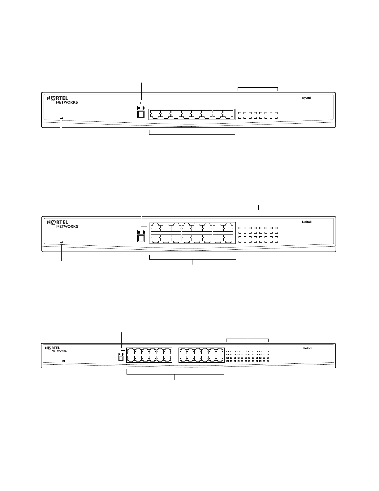
The front panel of each switch contains:
• RJ-45 10BAS E-T/100BASE-TX Ethernet ports
• One Power LED
• One 10/100 Link/Acti vity LED per port
• One half-duplex ( HDX) / full-duplex (FDX) LED per port
• MDI/MDI-X push button to set port 1 to uplink ( MDI) mode
Figure 1-1
, Figure 1-2, and Figure 1-3 illustrate the front panel of the BayStack
70-8T 10/100 Ethernet Switch, BayStack 70-16T 10/100 Ethernet Switch, and
BayStack 70-24T 10/100 Ethernet Switch, respectively.
1-2
206375-A
Page 19
Introduction
LED
Power On
Power LED
MDI/MDI-X button
MDIX/MDI
123456
10BASE-T/100BASE-TX Ports
78
display
1234567
Figure 1-1. Front Panel of the BayStack 70-8T 10/100 Ethernet Switch
LED
display
135791113
2 4 6 8 10 12 14 16
Power On
MDI/MDI-X button
1357911
MDIX/MDI
2 4 6 8 10 12
13 15
14 16
8
15
10/100 Link Activity
HDX/FDX
10/100 Link Activity
HDX/FDX
10/100 Link Activity
HDX/FDX
70-8T Switch
9203EA
70-16T Switch
Power LED
10BASE-T/100BASE-TX Ports
Figure 1-2. Front Panel of the BayStack 70-16T 10/100 Ethernet Switch
LED
display
135791113
2 4 6 8 10 12 14 16
15
17 19 21 23
18 20 22 24
10/100 Link Activity
HDX/FDX
10/100 Link Activity
HDX/FDX
Power On
Power LED
MDI/MDI-X button
1357 57 911911
MDIX/MDI
2 4 6 8 8 8 10 1210 12
10BASE-T/100BASE-TX Ports
13 15
14 16
Figure 1-3. Front Panel of the BayStack 70-24T 10/100 Ethernet Switch
206375-A
9204EA
70-24T Switch
9210EA
1-3
Page 20

Installation and Reference for the BayStack 70 Series 10/100 Ethernet Switches
RJ-45 1 0BASE-T/100 BASE-TX Eth er n et Ports
The RJ-45 10B ASE-T/100B ASE-TX Ethernet ports connect the switch to ne twork
devi ces using standard unshielded twist ed-pair (UTP) cable. The BayStack 70
Series 10/100 Ethernet Switches does not support shielded twisted-pair (STP)
cable. Each port adapts to the correct network speed of 10 Mb/s or 100 Mb/s
through autonegotiation with the network interface card (NIC), hub, or other
switch connected to the BayStack 70 Se ries 10/100 Et he rnet Switche s. By default,
each Ethernet port is wired as an MDI-X port to connect end stations without
using a crossover cable.
MDI/MDI-X Button
The MDI/MDI-X push button con verts port 1 from an MDI-X (normal) port to an
MDI (uplink) port to allow you to connect the switch to another Ethern et switch
without a crosso ver cable.
Note:
Observe sta ndard network ing guidelines when inst alling or connectin g a
BayStack 70 Series 10/100 Etherne t Switches to additional devices.
Refer to Appendix B, “Cables and Connectors,” for more information about
MDI/MDI-X ports and cabling.
1-4
206375-A
Page 21
2 4 6 8 10 12 14 16
135791113
10/100 Link Activity
HDX/FDX
10/100 Link Activity
HDX/FDX
15
18 20 22 24
17 19 21 23
Introduction
LEDs
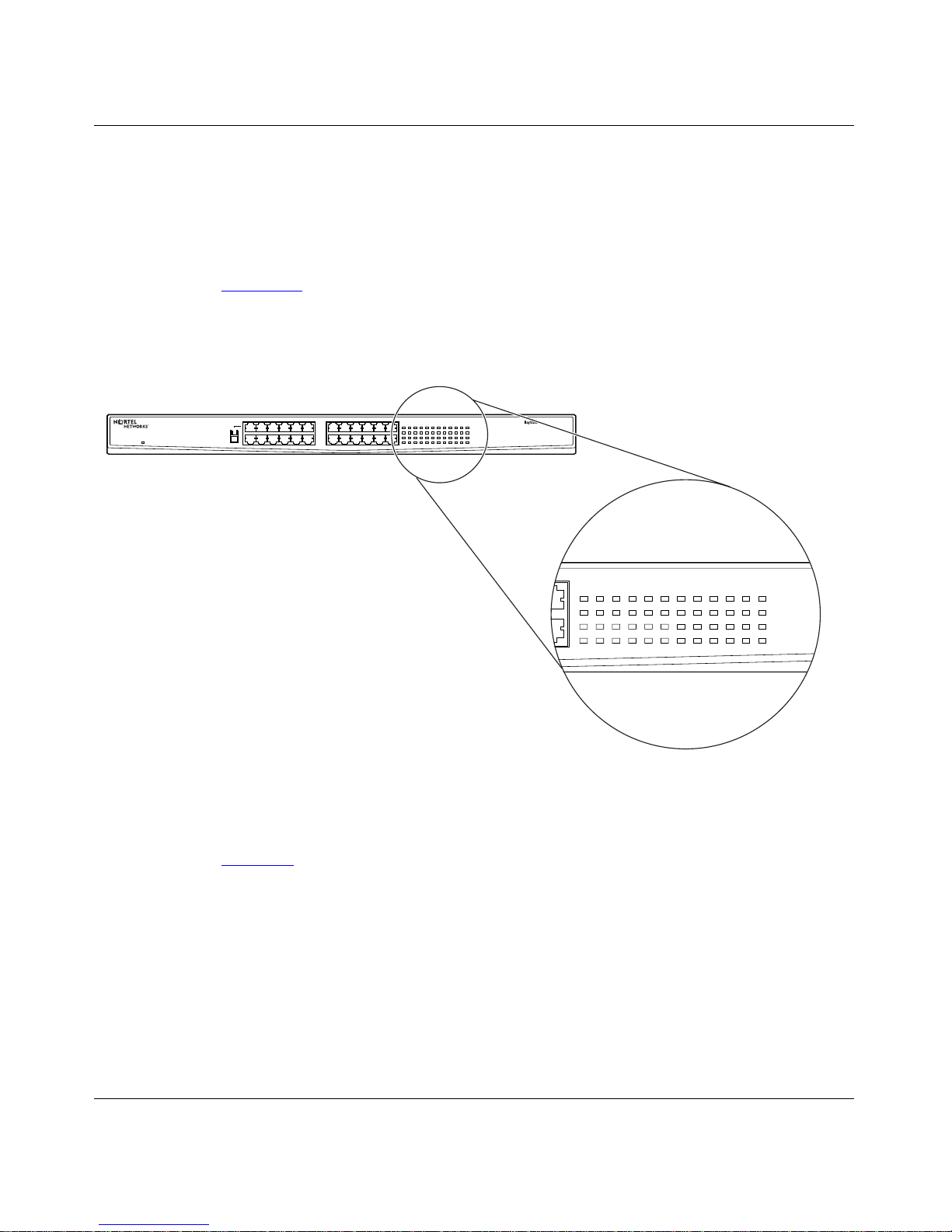
The LEDs on the BayStack 70 Series 10/100 Ethernet Switches allow you to
identify informa tion about the performanc e and status of the switch inclu ding link
activity, data transmission speed, and duplex mode.
Figure 1-4
shows the LEDs on the front panel of the BaySta ck 70-24T 10/100
Ethernet Switch. Front pa nel LEDs for the BayStack 70-8T 10/100 Ethernet
Switch and BayStack 70-16T 10/100 Ethernet S witch are identical.
135757 911911
Power On
MDIX/MDI
2 4 6 8 8 8 10 1210 12
13 15
14 16
135791113
2 4 6 8 10 12 14 16
15
17 19 21 23
18 20 22 24
10/100 Link Activity
HDX/FDX
10/100 Link Activity
HDX/FDX
70-24T Switch
Figure 1-4. BayStack 70-24T 10/100 Ethernet Switch LEDs
206375-A
Table 1- 1 provides descriptions of the LEDs.
9316EA
1-5
Page 22

Installation and Reference for the BayStack 70 Series 10/100 Ethernet Switches
Table 1-1. Description of Switch and Port Status LEDs
Type Label Color Activity Description
Port Status 10/100
Link/Activity
Port Mode HDX/FDX Green On Port is operating in full-duplex mode.
Power Pow er Green On Power is being supp li ed to the switch.
Yellow On Port is connected at 10 Mb/s.
Yellow Blinki ng 10 Mb/s acti vity is occurring on the port.
Green On Port is connected at 100 Mb/s.
Blinking 100 Mb/s acti vity is occurring on the port.
Off No link is established on the port.
Off Port is operating in half-duplex mode.
Off Power is not bei ng supplied to t he switch.
Rear Panel
This section provides rear panel details for the BaySt ack 70-8T 10/100 Ethernet
Switch and BayStack 70-16T 10/100 Ethernet S witch and separate details for the
BayStack 70-24T 10/100 Ethernet Switch.
Rear Panel of the BayStack 70-8T 10/100 Ethernet Switch and
BayStack 70-16T 10/100 Ethernet Switch
1-6
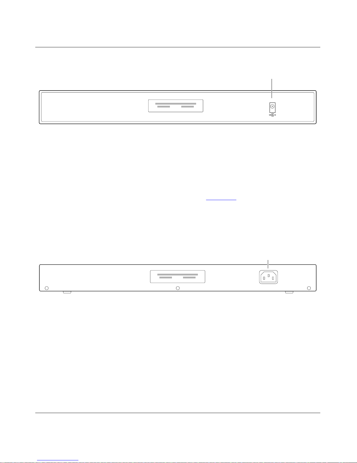
The rear panel of the BayStack 70-8T 10/100 Ethe rnet Switch and BayStack
70-16T 10/100 Ethernet Switch contains a power receptacle for the AC to DC
power adapter that ships with the switch. Refer to “
DC Power Adapter” on
page 1-8 for details regarding the power adapters. A label on the rear panel
displays the date, manufacturing model number, order number, and seria l number
of the switch.
The rear panel of the BayStack 70-8T 10/100 Ethe rnet Switch and rear panel of
the BayStack 70-16T 10/100 Ethernet Switch are identical and are illustrated in
Figure 1-5
.
206375-A
Page 23
DC power
adapter socket
5Vdc
-
Figure 1-5. Rear Panel of the BayStack 70-8T 10/100 Ethernet Switch and
BayStack 70-16T 10/100 Ethernet Switch
Rear Panel of the BayStack 70-24T 10/100 Ethernet Switch
The rear panel of the BayStack 70-24T 10/100 Ethe rnet Switch contains a
standard A C power conne ctor , as shown in Figure 1-6
. A separate power adapter is
not required for the BayStack 70-2 4T 10/100 Ethernet Switch. A label on the rear
panel displays the date, manufacturing model number, order number, and serial
number of the switch.
Introduction
+
9235EA
AC power
connector
Figure 1-6. Rear Panel of the BayStack 70-24T 10/100 Ethernet Switch
AC LINE
100-240 VAC
50-60 Hz
1.2A MAX
9031EB
206375-A
1-7
Page 24
Installation and Reference for the BayStack 70 Series 10/100 Ethernet Switches
DC Power Adapter
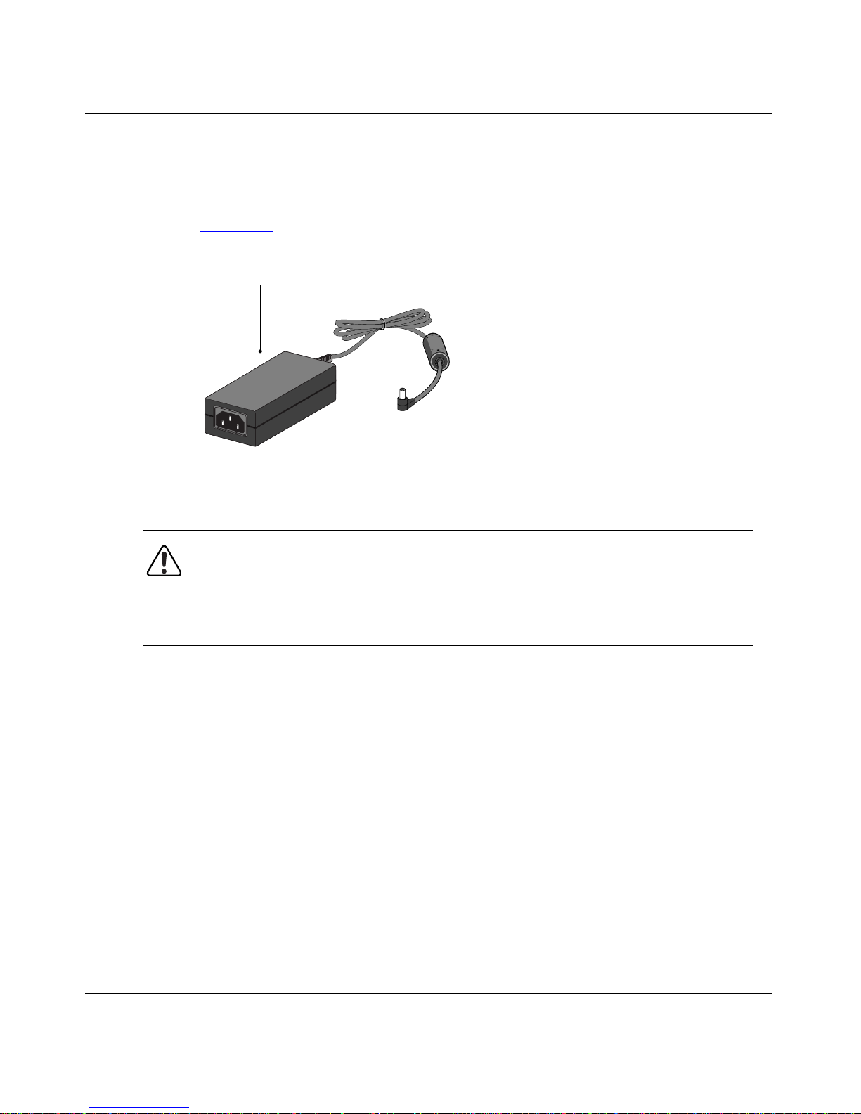
The BayStack 70-8T 10/100 Ethernet Switch and BayStack 70-16T 10/100
Ethernet Switch are shipped with a power adapter and cord, as shown in
Figure 1-7.
Power cord
adapter
9331FA
Figure 1-7. DC Power Adapter
Warning:
supply powe r to that switch. Read the amperage label on the po wer adapte r to
be sure it is the correct adapter for your switch.
Do not use the 8-port adapter (5 V DC/3 Amp) with a 16-port switch.
Do not use the 16-port adapter (5 V DC/4 Amp) with an 8-port switch.
The BayStack 70-8T 10/100 Ethernet Switch is shipped with a 5 V DC/3 Amp
power adapter. Be sure to use this 3 Amp adapter only with the 8-port switch.
The BayStack 70-16T 10/100 Ethernet Switch is shipped with a 5 V DC/4 Amp
power adapter. Be sure to use this 4 Amp adapter only with the 16-port switch.
Cable Holder
A small plastic clip, or hold er, can be screwed into the base of the switch to hold
the power adapter cable in place. The hole for the cable holde r is loca ted on the
bottom of the switch, near the DC power receptacle.
Use only the power adapter that was shipped with your switch to
1-8
206375-A
Page 25

Cooling Fans
Variable-speed cooling fans in the BayStack 70-16T 10/100 Ethernet Switch and
BayStack 70-24T 10/100 Ethernet Switch provide cooling for the internal
components. When you install the switch, be sure to allow enough space on both
sides of the switch for adequate air flow around the switch.
Features
The BayStack 70 Series 10/100 Ethernet S witches has the following key features:
• Eight (BayStack 70-8T 10/100 Ethernet Switch), 16 (BayStack 70-16T 10/
Introduction
100 Ethernet S witch), or 24 (BayStack 70-24T 10/100 Ethernet Switch)
autosensing 10/1 00 Mb/s Ethe rnet port s to pro vide f ast inf ormati on excha nge,
resource sharing, and client or peer-to-peer communication using standard
Category 5 unshielded twisted pair (UTP) cable
• Automatic address learning to build MA C frame forwarding information
tables, as shown in Table 1-2
Table 1-2. MAC Address Quantities
Model MAC Addresses in Information Table
BaySt a ck 70-8 T
10/100 Ethernet
Switch
BaySt a ck 70-1 6T
10/100 Ethernet
Switch
BaySt a ck 70-2 4T
10/100 Ethernet
Switch
Up to 8,000 MAC addresses are supported. Ther efore, the switch
can support networks with up to 8,000 devices.
Up to 12,000 MA C addresses are supp orted. Theref or e, the sw itch
can support networks with 12,000 devices.
Up to 12,000 MA C addresses are supp orted. Theref or e, the sw itch
can support networks with up to 12,000 devices.
206375-A
1-9
Page 26

Installation and Reference for the BayStack 70 Series 10/100 Ethernet Switches
• Filtering and forw arding incoming and outgoing traffic to the appropria te
route without slowing down the traffic
• Store-and-for ward forwarding mode to minimize erro neous packets on the
network
• Autonegotiation on each port with the follo wing four modes:
— 10BASE-T half-duplex
— 10BASE-T full-duple x
— 100 BASE-TX half-duplex
— 100 BASE-TX full-duplex
Note:
In order for ports on a
BayStack 70 Series 10/100 Ethernet Switch
to
operate in full-duplex mode, the switch must be connecte d to a device that
supports autonegotiation in accordance with the IEEE 802.3u specification.
• Back pressure in half-dup lex mode
• Automatic polarity det ection and correction
• Easy plug-and-play installation with no software to configure , whic h sa ves
time and minimizes the potential for configuration errors
• A comprehensive LED indicator panel for monitoring switching condition
and indi vidual port status
• Conformity to the IEEE 802.3u 100BASE-TX Class II standard
• Conformity to the 802.3 10BASE-T standard
• Per port buffer sizes, as shown in Table 1-3
Table 1-3. Buffer Sizes
Model Buffer Size
BayStack 70-8T 10/100 Ethernet Switch 64 kilobytes (KB)
BayStack 70-16T 10/ 100 Ethernet Switch 128 KB
BayStack 70-24T 10/ 100 Ethernet Switch 128 KB
• MDI/MDI-X push button switc h for uplink capability
1-10
206375-A
Page 27

Introduction
• External universal power adapter, as shown in Table 1-4
Table 1-4. External Power Adapters
Model External Power Adapter
BayStack 70-8T 10/100 Ethernet Switch 5V 3A
BayStack 70-16T 10/ 100 Ethernet Switch 5V 4A
BayStack 70-24T 10/100 Ethernet Switch n/a (This model has an internal power
supply and uses a standard power cor d.)
206375-A
1-11
Page 28

Page 29

Chapter 2
Network Configura tion
The BayStack 70 Series 10/100 Ethernet Switch is designed to provide flexibility
in configuring your netw ork connections. Ea ch switch in the se ries can be used as
a standalone device or can be used with 10 Mb/s and/or 100 Mb/s hubs or other
interconnection devices in various configurations. The configuration examples in
this chapter illustrate the integration of the switches in network environments of
all sizes and types. Thes e examples include a network of a few workstations
connected to a printer or a segmented networ k with multiple users or workgroups
and other networking devices.
Benefits of Using Switching Technology
Ethernet switches provide private, dedicated, 10 Mb/s or 100 Mb/s capacity to
each connected PC/server or hub/workgroup segment, which is a significantly
higher capacity than in a shared environment. The higher bandwidth enables the
use of applications such as multimedia, imaging, video, or high-performance
client-server functions among users who are spread out over the network.
This improvement is accomplished very easily, with no change to the desktop
(such as, network interface cards or softwa re and network wiring). As a r esult, the
performance upgrade and the applicatio ns en abled by th e switc h are obta ined v ery
quickly and at a low cost.
Ethernet switches significantly increase network throughput by segmenting
network traffic. Switches check traffic coming in to each port to learn which
network device is located on which segment . Base d on this information, switches
forward c ro ss-segment tra ffic only to the appr opriate se gment. The traffic will not
show up in the other segments because it is filtered out. In this way, ne twork
capacity is fully reserved for traffic destined for that segment only, and other
segments will not be saturated with unnecessary traffic.
206375-A
2-1
Page 30

Installation and Reference for the BayStack 70 Series 10/100 Ethernet Switches
Types of Ethernet Switches
Ethernet switches can be classified as desktop switches or as segment switche s.
A desktop switch is designed to support one or a few PCs per port. It is generally
used when individuals need the full 10 Mb/s network throughput to support their
applications. Often, these switches support only a single MAC (media access
control) address per port, have high-speed 100 Mb/s ports to connect to
high-po we r servers, and are relatively inexpensive c ompared to a segment swi tch.
A segment switch, in contrast, is designed to support an entire workgroup on
each port, with each port having significant memory buffering and supporting
thousands of MAC addresses.
Switches can also be classified by speed. As the name suggests, 10 Mb/s switches
support only 10 Mb/s connections. Simil arly, 100 Mb/s switches support only 100
Mb/s connections. Some types of 10+100 Mb/s switches have primarily 10 Mb/s
ports with one or a few 100 Mb/s ports. Autosensing 10/100 Mb/s switches such
as the BayStack 70 Series 10/100 Etherne t Switch support 10 Mb/s or 100 Mb/s
connections on each port, and offer great versatility and adaptability.
2-2
206375-A
Page 31
Desk t op Switching
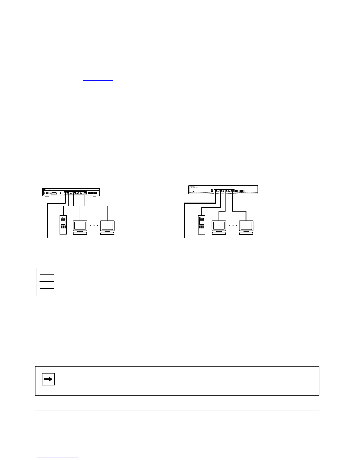
Figure 2-1 illustrates a BayStack 70- 8T 10/100 Ethernet Switch used as a desktop
switch to rebuild a small network that e nables users to have 100 Mb/s access to a
file server or network center. You can use the BayStack 70-16T 10/100 Ethernet
Switch or
similar application, if you have more users or devices to connect.
You can replace your existing 10BASE- T hub with a BayStack 70 Seri es 10/100
Ethernet Switch in order to access devices with various transmissi on speeds or to
connect to a larger num b er of use rs.
Before After
BayStack 70-24T 10/100 Ethernet Switch
Network Configuration
as a desktop switch, in a
10BASE-T hub
Server Up to 6 users
To
Network
Center
Key
10 Mb/s
100 Mb/s
200 Mb/s
- 6 users share 10 Mb/s (10/6 Mb/s per user)
- Server bottleneck (10 Mb/s bandwidth)
- Network center bottleneck (10 Mb/s bandwidth)
Model 810
BayStack 70-8T Switch
Server Up to 6 users
To
Network
Center
- 6 users; each with dedicated 100 Mb/s bandwidth
- Server with dedicated 100 Mb/s bandwidth
- Network center with dedicated 100 Mb/s full-duplex
bandwith (200 Mb/s bidirectional)
70-8T Switch
9305EA
Figure 2-1. Using a BayStack 70 Series 10/100 Ethernet Switch as a Desktop Switch
Note:
If a full-duplex a dapter card is installed in the server or PC, a 200 Mb/s
connection is poss ible on the port where the server or PC is connected.
206375-A
2-3
Page 32

Installation and Reference for the BayStack 70 Series 10/100 Ethernet Switches
Segment Switching
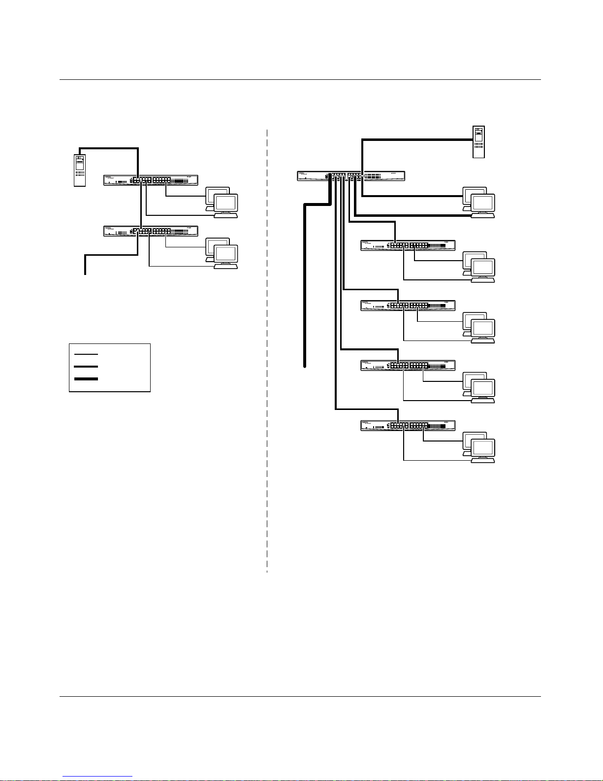
The BayStack 70 Series 10/100 Ethernet Switch can segment a network into
multiple connected pieces, increasing overall bandwidth and throughput.
Figure 2-2
illustrates a
BayStack 70-24T 10/100 Ethernet Switch
segmenting
networks that are built with BayStack 60-24T Ethe r net Hubs. Adding a
70-24T 10/100 Ethe rnet Switch
to hub configurations a llows you to connect more
users and devices and to provide faster throughput across your network.
BayStack
2-4
206375-A
Page 33
Network Configuration
Server
To
Network
Center
Key
10 Mb/s
100 Mb/s
200 Mb/s
Before
BayStack 60-24T
Hub
60-24T Hub
60-24T Hub
Up to
44 users
BayStack 70-24T
Switch
To
Network
Center
After
Server
70-24T Switch
Up to 18
users
Up to 23
60-24T Hub
users
Up to 23
60-24T Hub
users
Up to 23
60-24T Hub
users
Up to 23
60-24T Hub
users
- 44 users share 10 Mb/s (10/44 Mb/s per user)
- Server bottleneck (10 Mb/s bandwidth)
- Network center bottleneck (10 Mb/s bandwidth)
-Total of 44 users
- Four sets of 23 users; each set shares 10 Mb/s
(10/23 Mb/s per user)
- Addition of 18 users; each with dedicated
100 Mb/s bandwidth
- Server with dedicated 100 Mb/s bandwidth
- Network center with dedicated 100 Mb/s full-duplex bandwidth
(200 Mb/s bidirectional)
- Total of 110 users
9303EA
Figure 2-2. Using a BayStack 70 Series 10/100 Ethernet Switch as a Segment Switch
206375-A
2-5
Page 34
Installation and Reference for the BayStack 70 Series 10/100 Ethernet Switches
A
Extending a Network
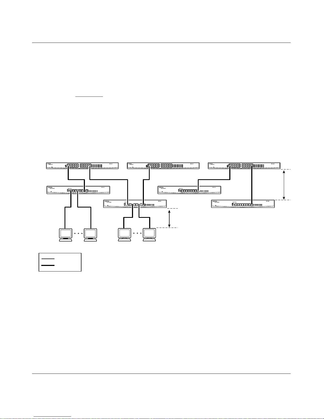
Ethernet specifications limi t the length of cable between hubs and PCs to
100 meters (m) for a total diameter of 200 m. By adding Fast Ethernet switches
between hubs, the netwo rk is e xpand ed by 2 00 m with the additi on of e ach switch .
Figure 2-3
integrated with three
illustrate s a networ k of
BayStack 70-24T 10/100 Ethernet Switch
any combination of the BayStack 70 Series 10/100 Ethernet Switches, depending
on the needs of your network. You can add numerous workstations, printers,
servers, or other hubs and switches to this configuration to include all the end
stations on your extended network.
BayStack 70-8T 10/100 Ethernet Switches
es. You can use
BayStack 70-24T
Switch
70-24T Switch 70-24T Switch 70-24T Switch
70-8T Switch
BayStack 70-8T
Switch
Key
10 Mb/s
100 Mb/s
BayStack 70-24T
Switch
BayStack 70-8T
70-8T Switch
Switches
100 m
BayStack 70-24T
Switch
70-8T Switch
100 m
70-8T Switch
9321E
Figure 2-3. Using BayStack 70 Series 10/100 Ethernet Switches for Network Extension
2-6
206375-A
Page 35
Network Configuration
Bridging from 10BASE-T to 100BASE-TX Networks
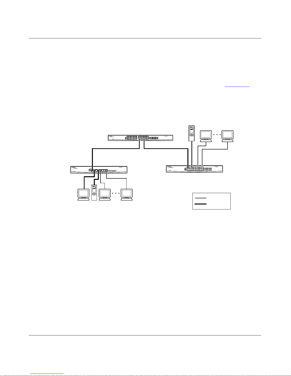
The BayStack 70 Series 10/100 Ethernet Switch can function as a two- port bridge
connecting traditional 10BASE-T Ethernet networks to 100BASE-TX Fast
Ethernet netw orks. User s requi ring incr eased networ k bandwidt h can be upgr aded
to 100 Mb/s while remaining connected to the rest of the network. Figure 2-4
illustrates a BayStack 70-8T 10/100 Ethernet Switch and a BayStack 70-16T 10/
100 Ethernet Switch connected by a
well as attached to se veral other network and end station devices
BayStack 70-24T 10/100 Ethernet Switc h, as
.
Server
70-16T Switch
BayStack 70-16T
Switch
Key
10 Mb/s
100 Mb/s
9323EA
BayStack 70-8T
Switch
70-8T Switch
BayStack 70-24T
Switch
70-24T Switch
Figure 2-4. Bridging 10 Mb/s Networks to 100 Mb/s Networks
206375-A
2-7
Page 36
Installation and Reference for the BayStack 70 Series 10/100 Ethernet Switches
Power Workgroups
The BayStack 70 Series 10/100 Ethernet S witch increases bandwidth for power,
or high-densit y, workgroups and strengthens network throughput.
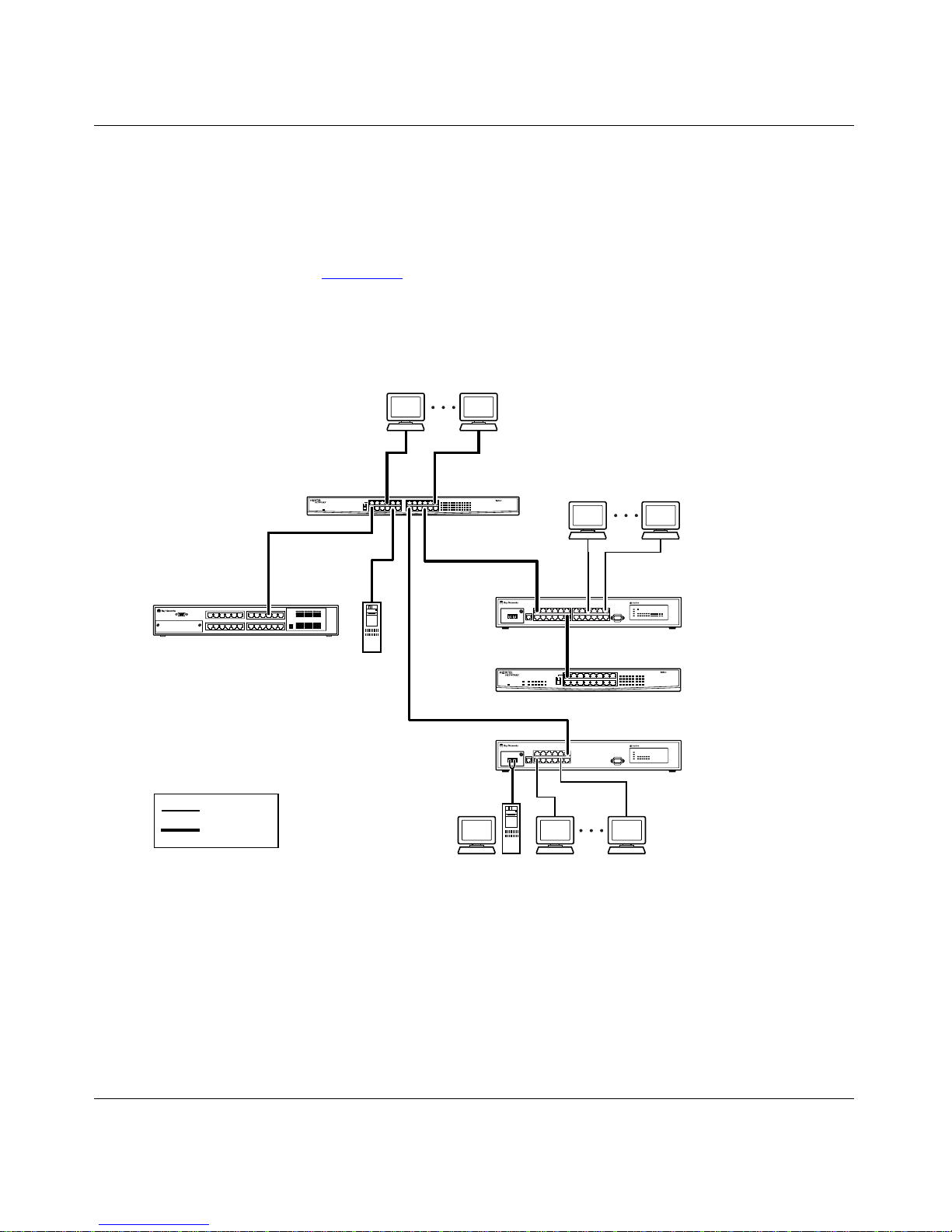
As shown in Figure 2-5
BayStack 70-24T 10/100 Ethernet Switch
, a
connects to
several BayStack switches, as well as high-density end stations and servers. End
users can use 10 Mb/s or 100 Mb/s connections throug hout this network, as
determined b y thei r bandwidth requirements.
BayStack 70-24T
Switch
BayStack 450-24T
Switch
Server
70-24T Switch
303
BayStack 303
Switch
60-16T Hub
BayStack 60-16T
Hub
2-8
Key
10 Mb/s
100 Mb/s
Figure 2-5. Power Workgroup Connections
304
BayStack 304
Switch
9304EB
206375-A
Page 37

This chapte r provides in formation about and procedures for c he cking the package
contents, prepar ing the site, and performing and ver ifying the installat ion of the
BayStack 70 Series 10/100 Ethernet Switch.
Package Contents
Chapter 3
Installation
Unpack the contents of the package and ve rify the items against the following list:
• One of the followi ng BayStack 70 Series 10/100 Ethernet Switches:
— BayStack 70-8T 10/100 Ethernet Switch (8-port 10/100 Mb/s switch)
— BayStack 70-16T 10/100 Ethernet Switch (16-port 10/100 Mb/s switch)
— BayStack 70-24T 10/100 Ethernet Switch (24-port 10/100 Mb/s switch)
• Four self-adhesive rubber feet for pla cing the switch on a flat surface
• Plastic cable holder and metal screw for securing the power cable or power
adapter cord
• Wall Mount Kit, including screws and f asteners (for the BayStack 70-8T 10/
100 Ethernet S witch or BayStack 70-16T 10/100 Ethernet Switch only)
• Rack Mount Kit, including brackets and screws (for the Ba ySt ack 70 -2 4T 10 /
100 Ethernet Switch only)
• One of the followi ng power adapters
— BayStack 70-8T 10/100 Ethernet Switch: 5V 3A DC power adapter
— BayStack 70-16T 10/100 Ethernet Switch: 5V 4A DC power adapter
206375-A
3-1
Page 38

Installation and Reference for the BayStack 70 Series 10/100 Ethernet Switches
• Optional, country-specific power cord, which can be purchased with your
switch
• Warranty card
• Safety Information car d
Operating Environment
Before you begin installing your switch, prepare the installation site . Make sure
the operating environment, as listed in Appendix A, “Te chnical Specifications,”
meets the physical requirements of the switch.
Install your BayStack 70 Series 10/10 0 Ethernet Switch in a vent ilate d area that is
dust free and away from heat vents, warm air exhaust from other equipment, and
direct sunlight. Avoid proximity to large electric moto rs or other electromagnetic
equipment.
Power Specifications
BayStack 70-8T 10/100 Ethernet Switch
The
Ethernet Switch
10/100 Ethernet Switch
power supply. You can purchase a country-specific power cord for any BayStack
70 Series 10/100 Ethernet Switch.
Before connecting the switch to power with any power cord, make sure the power
cord has a plug on the other end that is appropriate for the country where you are
using the switch.
Danger:
Use only power cords with a grounding path. Without a proper
ground, a pers on touching the unit is in d anger of recei vi ng an el ectrica l shock.
Lack of a grounding path to the unit may result in e xcessive conducted or
radiated emissions.
feature an external 5 V DC po wer adapter. The
BayStack 70-16T 10/100
and
BayStack 70-24T
has an internal (100 to 240 V AC, 50 to 60 Hz) universal
3-2
206375-A
Page 39

Installation
Insta lling th e Switch
Before installing the switch:
Unpack th e swi tch .
1.
Choose a location near the devices to be connected and close to an
2.
electrical outlet.
Proceed to “Installing the BayStack 70 Series 10/100 Ethernet Switch on
3.
a Flat Surface” or “Mounting the BayStack 70-24T 10/100 Ethernet
Switch in a Rack.”
Installing the BayStack 70 Series 10/100 Ethernet Switch on a Flat
Surface
BayStack 70 Series 10/100 Ethernet Switc h
The
appropriate flat, level surface that can safely support the weight of a switch and its
attached cables, a s long as there is adequate space around the unit for ve ntilation
and access to cable connectors.
can be mounted onto any
Caution:
When the
BayStack 70 Series 10/100 Ethernet Switch is installed in
a stack on a shelf or tabletop, the accumula ted weight of the port cables
increases with the height of the shelf or tabletop.
To install the sw itch on a desk top or any othe r flat su rface :
Install the self-adhesive rubber pads on the bottom of the switch.
1.
Peel off the protective backing from the rubber pads and apply one at each
marked location on the bottom of the switch.
Set the swit ch on a de sk top or any other flat surfa c e.
2.
For pr ope r ventil ation, make sure that the switch has at least 2 inches (5.1 cm)
of space on each side and 5 inches (12.7 cm) of space at the back.
Caution:
Restricted airflow could cause overheating of the components. Be
sure to provide adequate ventilation space on the sides and rear of the switch.
206375-A
3-3
Page 40

Installation and Reference for the BayStack 70 Series 10/100 Ethernet Switches
Attach any additional devices to the ports in your switch.
3.
For instr uct ions to connect to additional switches or other devices, refer to
Connecting Devices to the Switch” on page 3-5.
“
Mounting the BayStack 70-24T 10/100 Ethernet Switch in a Rack
The BayStack 70-24T 10/100 Ethernet Switch occupies a 1.6 unit (1.6u) rack
space and can be installed in most standa rd 19-inch equipment racks. The rack
must be grounded to the same grounding electrode used by the power service in
the area. The ground path must be permanent a nd must not exc eed 1 ohm of
resistance from the rack to the grounding electrode.
Caution:
When mounting this device in a rack, do not place units directly on
top of one another in the rack. Each unit must be individually secured to the
rack with appropriate mounting brackets. Mounting brackets are not designed
to support multiple units.
To mount the BayStack 70-24T 10/100 Ethernet Switch in a standard 19-inch
equipment rack, you need these tools and materials:
• Two mounting brackets supplied from the Rack Mount Kit
• Eight screws supplied from the Rack Mount Kit to attach the mounting
brackets to the switch
• Four screws and nylon washers supplied from the Rack Mount Kit to attach
the mounting brackets to the rack
• #1 Phillips scre wdrive r
• #2 Phillips scre wdrive r
To install the sw itch in a rack:
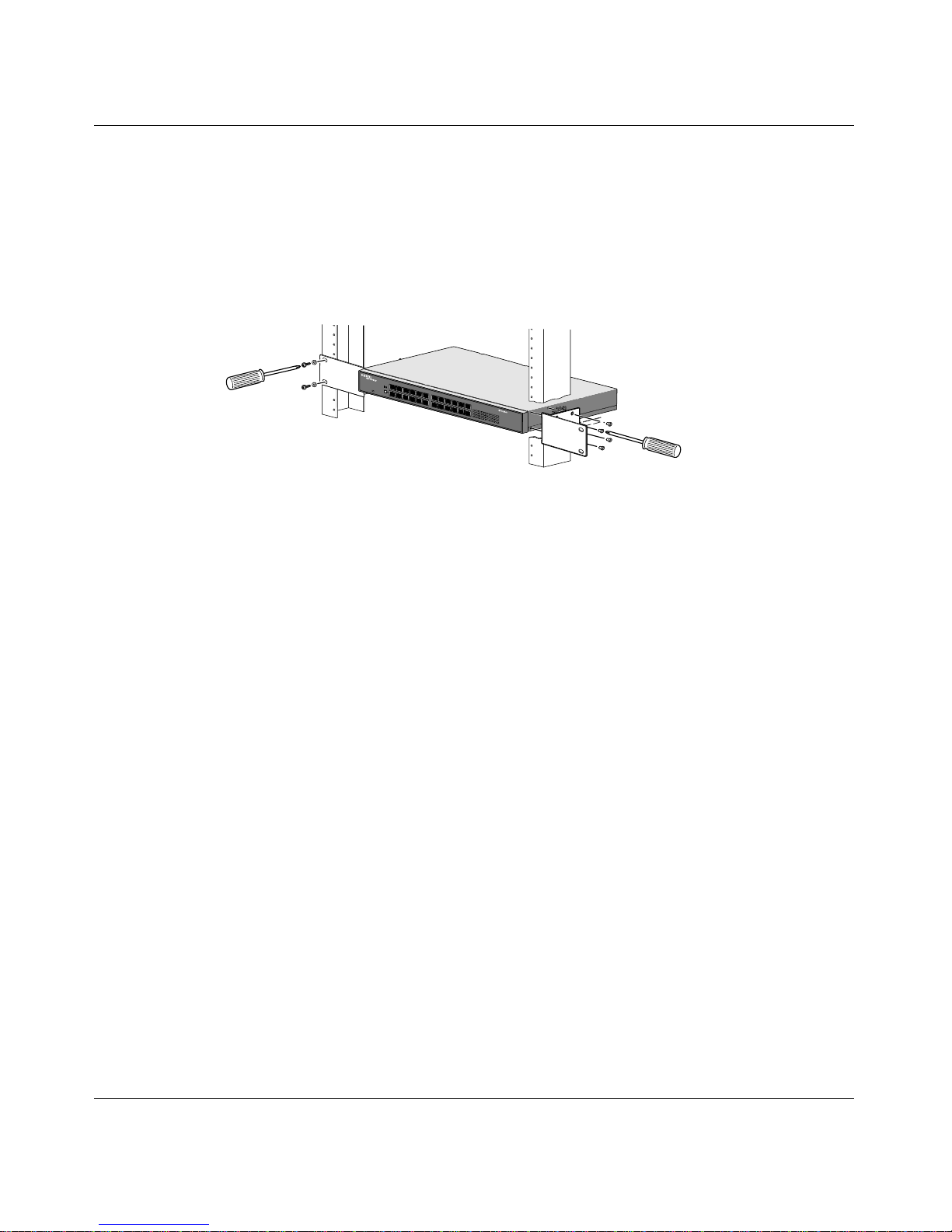
Attach the mounting brackets to the sides of the switch as illustrated in
1.
Figure 3-1.
Hold a mounting bracket against each side of the switch and align the
countersunk screw hole s in the bracket with the bracket mounting holes in the
switch.
Insert the screws provided in the Rack Mount Kit through each bracket
2.
and into the bracket mounting holes in the switch.
3-4
206375-A
Page 41
Installation
Using a #1 Phillips screwdriver, tighten the screws to s ecure each bracket.
3.
Hold the switch with the mounting holes in the bracket s align ed w i th the
4.
holes in the rack.
Insert two screws, a pp ropr iat e for your 19-inch rac k, into ea ch of the
5.
mounting brackets and tighten the screws.
70-24T Switch
9350FA
Figure 3-1. Installing the Switch in a Rack
Connecting De vices to the Switch
You can connect the
that conforms to the IEEE 802.3 Etherne t standard, such as the following devices:
• Ethernet networking devices
• Individual workstations or servers
• Other switches, bridges, or hubs
The HDX/FDX LED on all
panels indicates whether the switch is operating in half- or full-duplex mode.
When the HDX/FDX LED is on, the port is operating in full-duplex mode
(meaning the port is ope rating at either 20 Mb/s or 200 Mb/s, depending on the
connecting device). When the HDX/FDX LED is off, the port is operating in
half-duplex mode, which is 10 Mb/s or 100 Mb/s.
BayStack 70 Series 10/100 Ethernet Switch to any device
BayStack 70 Series 10/100 Ethernet Switch
front
206375-A
3-5
Page 42

Installation and Reference for the BayStack 70 Series 10/100 Ethernet Switches
You can connect to another de vice through any of the ports on the switch. The
MDI/MDI-X button elimina tes the need to use a crossov er twisted pair cable when
connecting similarly wired devices. You can configure port 1 on a BayStack 70
Series 10/100 Ethernet Switch to uplink or normal mode with the MDI/MDI-X
button, using the following guidelines:
• Set the MDI/MDI-X button to the MDI-X (Normal) position and use a
standard straight-through UTP cable if the remote end of the cable is
connected to an MDI wired device such as a PC, a server, or a router.
• Set the MDI/MDI-X button to the MDI (Uplin k) posi tion and use a
straight-through UTP cable if the remote end of the cable is connected to
an MDI-X wired devi ce suc h as a 10 Mb/s or 100 Mb/s hub or repe ater , or
for backbone c onnection to another switch.
By default, the UTP ports without the MDI/MDI-X button are normal
(MDI-X) ports and cannot be configured for uplink (MDI) wiring. I f you are
using an y por t except port 1 t o connect to another normal (MDI-X) port as on
a hub or repeater, you must use a crossove r twisted pair cable to connect the
two ports.
For further cabli ng guideline s, refer to Appendix B, “Cables and Connectors.”
Connecting Power
BayStack 70 Series 10/100 Ethernet Switch doe s not have a power on/off
The
switch. When you connect the AC power cord (or DC power adapter) to a suitable
AC power outlet, the switch powers up immediately.
Warning:
devi ce. The power cord must always be connected in a location that can be
accessed quickly and safely in case of an emergency.
Remov al of the power cord is the only way to turn off power to this
3-6
206375-A
Page 43

Installation
To connect power to the switch:
Connect the power adapter or power cord to the swit ch using one of the
1.
following methods:
— For the BayStack 70-8T 10/100 Ethernet Switch or BayStack 70-16T 10/
100 Ethernet S witch, connect the DC power adapter to the power adapter
receptacle on the rear panel of the switch. Then connect a standard power
cord to the ada pter.
Warning:
Use only the power adapter that was shipped with your switch to
supply powe r to that switch. Read the amperage label on the po wer adapte r to
be sure it is the correct adapter for your switch.
Do not use the 8-port adapter (5 V DC/3 Amp) with a 16-port switch.
Do not use the 16-port adapter (5 V DC/4 Amp) with an 8-port switch.
— For the BayStack 70-24T 10/100 Ethernet Switch, con nect one end of the
power cord to the power outlet on the rear panel of the switch.
Screw the plastic cable holder into the bottom of the switch, near the
2.
power receptacle.
Snap the pow er cord or power a dapter cord in to the cabl e hol de r to
3.
secure the cord to the sw it ch.
Connect the other end of the power cord to a standard power supply.
4.
The switch automatically sele cts the prope r voltage in the range of 100 to 240
volts, and the Power LED lights. The switch is now operational.
Verifyin g In s ta lla t ion
When power is applied to the switch, power-on self-tests are run. You can verify
proper orie ntation of the
the front panel LEDs.
Verify network communications by ensuring that all the necessary connections
hav e been made, that all connected resources can be accessed, a nd that the LED
indicators on t he s witch ar e functi oning p roperly. For ad ditional informatio n, refer
to Chapter 4, “Troubleshooting. ”
206375-A
BayStack 70 Series 10/100 Ethe rnet Swit ch by observ ing
3-7
Page 44
Installation and Reference for the BayStack 70 Series 10/100 Ethernet Switches
2 4 6 8 10 12 14 16
135791113
10/100 Link Activity
HDX/FDX
10/100 Link Activity
HDX/FDX
15
18 20 22 24
17 19 21 23
Checking the Diagnostic Displays
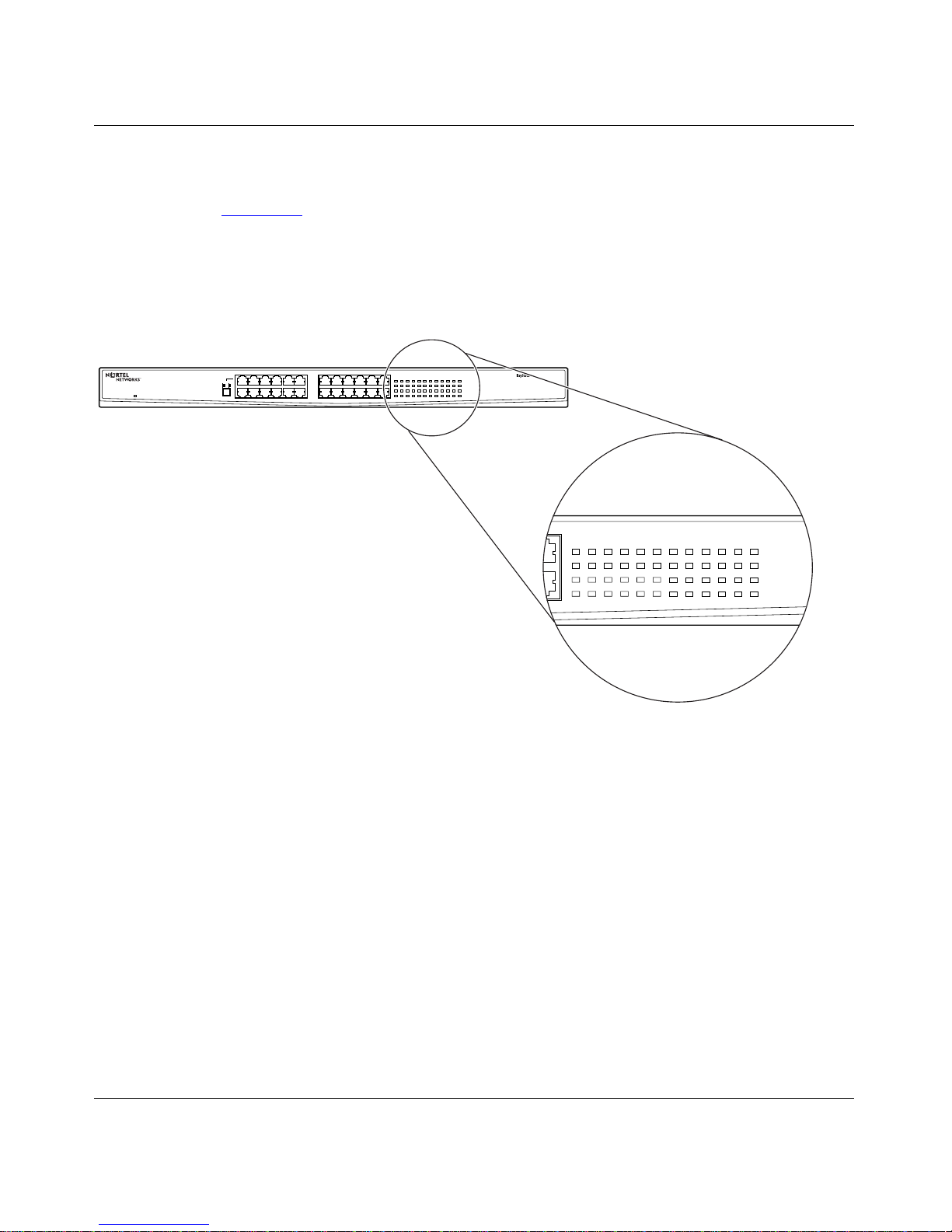
Figure 3-2 illustrates the LED indicators on theBayStack 70-24T 10/100 Et hernet
Switch. LEDs on the BayStack 70-8T 10/100 Ethernet Switch and BayStack
70-16T 10/100 Ethernet Switch are identical, although the re are only as many
LEDs as are require d for the ports on each mo d el.
135757 911911
Power On
MDIX/MDI
2 4 6 8 8 8 10 1210 12
13 15
14 16
135791113
2 4 6 8 10 12 14 16
15
17 19 21 23
18 20 22 24
10/100 Link Activity
HDX/FDX
10/100 Link Activity
HDX/FDX
70-24T Switch
Figure 3-2. BayStack 70-24T 10/100 Ethernet Switch LED Display
9316EA
3-8
206375-A
Page 45

Table 3- 1 describes the LEDs that monitor the BaySta ck 70 Series 10/100
Ethernet Switch.
Table 3-1. Description of Switch and Port Status LEDs
Type Label Color Activity Description
Installation
Port Status 10/100
Link/Activity
Port Mode HDX/FDX Green On Port is operating in full-duplex mode.
Power Pow er Green On Power is being supp li ed to the switch.
Yellow On Port is connected at 10 Mb/s.
Yellow Blinki ng 10 Mb/s acti vity is occurring on the port.
Green On Port is connected at 100 Mb/s.
Blinking 100 Mb/s acti vity is occurring on the port.
Off No link is established on the port.
Off Port is operating in half-duplex mode.
Off Power is not bei ng supplied to t he switch.
206375-A
3-9
Page 46

Page 47

This chapter provides m ethods for diagnosing problems with the BayStack 70
Series 10/100 Ethernet Switch.
Using the LED Display
Chapter 4
Troubleshooting
Use the LED display to help you identify the type of problem you have; then
check the following:
• Verify that the switch is powered on.
• Verify that each cable and port connection has the correct pin assignment and
no connections are loose.
• A good link on a port is verified when the Link/Activity LED is lit for that
port.
If the Power LED is not on:
• Verify that the po wer adapter and/or power co rd are securely attached to the
switch and to the power outlet.
• Verify that your AC power source is functioning properly.
If the Link LED is not on:
• Verify that the device connected to your switch has a proper ly fu ntioning
power supply.
• Try using a different port on your switch to connect to the device.
• Try using a different port on the device conn ec t ed to your switch.
206375-A
4-1
Page 48

Page 49

Table A- 1 in this appendix provides technical specifications for the BayStack 70
Series 10/100 Ethernet Switc h. Data applies to all three switches unless otherwise
specified.
Product Specifications
Appendix A
Technical Specifications
Table A-1. Tech nical Spec ifications
Item Description
Network Pr otocol and Standar ds Compa ti bil ity
Data Rate/Encoding
Interfaces
Electrical Specifi cations
Input power: 70-8T: 15 W, 5 V 3A
Power consumption: 70-8T: 15 W Maximum
IEEE 802.3 10BASE-T/100BASE- TX Ethernet
IEEE 802.3u 100 Mb/s Ethernet
10 Mb/s differential Manchester encoded
100 Mb/s MLT encoded
125 MHz signal rate
RJ-45 8-pin plug for 10BASE-T and 100BASE-TX
70-16T: 20 W, 5 V 4A
70-24T: 100 to 240 V AC, 50 to 60 Hz, 2A
70-16T: 20 W Maximu m
70-24T: 50 W Maximu m
206375-A
A-1
Page 50

Installation and Reference for the BayStack 70 Series 10/100 Ethernet Switches
Item Description
Physical Speci fications
Weight: 70-8T and 70-16T: 3.99 lb (1.81 kg)
70-24T: 5.3 lb (2.5 kg)
Dimensions: 70-8T and 70-16T:
(D) 8.3 x (W) 12.0 x (H) 1.6 in.
(D) 208.0 x (W) 304.7 x (H) 40.6 mm
70-24T:
(D) 12.1 x (W) 17.3 x (H) 1.7 in.
(D) 308.0 x (W) 437.5 x (H) 42.5 mm
Environmental Specifications
Operating temperature: 0° to 40° C
Storage tempe rature: -20° C to 65° C
Operating hum idity: 20% to 80% maximum relative humidity,
noncondensing
Storage humidity: 70-8T and 70-16T :
5% to 90% maximum relati ve humidity,
noncondensin g
70-24T:
10% to 90% maximum relative humidity,
noncondensing
Electromagnetic Emissions
Meets requirements of: FCC Part 15, Subpart B, Class A
AS/NZS 3548 Class A
EN55 022 (CISPR 22) Class A
VCCI Class A ITE
BCIQ
A-2
206375-A
Page 51

Item Description
Electromagnetic Susceptibility
Meets requirements of: EN 50082-1
Electrostatic discharge (ESD): EC 801-2, Level 2/3
Radiated electromagnetic field: EC 801-2, Level 2
Electrical f ast transient/burst: EC 801-4, Level 2
Electrical surge: EC 801-5, Level 1/2
Technical Specifications
Safe t y A gen cy Approval s
Perf ormance Specificat ions
Aggregate ban dwdth: 70-8T: 800 Mb/s
Packet filt ering/fo rwarding rate: 14,800 fra me s/second, maximum on 10 Mb/s port
Forwarding modes: Store- and-forward
Network latency: Less than 80 microseconds for 64- byte frames in
Address database size: 70-8T:
UL 1950 or NRTL
CSA C22.2 #950
TUV
NOM
70-16T: 1.6 Gb/s
70-24T: 2.4 Gb/s
148,000 fram es/second, maximum on 100Mb/s port
store-and-forward mode for 10 Mb/s to 100 Mb/s
transmission
8,000 media access control (MAC) addresses per
system
70-16T:
12,000 MAC addresses per system
Addressing: 48-bit MA C address
Queue buffer, per port: 70-8T: 64 kilobytes (KB)
206375-A
70-24T:
12,000 MAC addresses per system
70-16T and 70-24T : 128 KB
A-3
Page 52

Page 53

Cables and Connectors
This appendix provides specifi cations for cables and connectors use d for the
BayStack 70 Series 10/100 Ethernet Switch.
10BASE-T/100BASE-TX UTP Cable
Appendix B
For 10B AS E-T a nd 100BASE-TX connections, use Cate gor y 5, 8- wire uns hie lded
twisted pair cable. Configure your network according to the following guidelines:
• Use a maximum segment length of 100 meters.
• Use an 8-pin modular plug (RJ-45).
Table B-1
Table B-1. RJ-45 Connector Pin Assignments
RJ-45
10BASE-T/100BASE-TX
Ethernet Port
8
1
shows the RJ-45 connector pin assignments for MDI-X and MDI ports.
MDI
(Uplink)
Port
1882.6
Pin
1 RX+ (Receive) RX+ TX+
2 RX- (Receiv e) RX- TX-
1
8
3 TX+ (Transmit) TX+ RX+
4 Not used Common-Mode
5 Not used CMT
6 TX- (Transmit) TX- RX-
10BASE-T MDI-X
(Normal) Port
100 BASE-TX
MDI-X Port
Terminated (CMT)
206375-A
7 Not used CMT
8 Not used CMT
B-1
Page 54
Installation and Reference for the BayStack 70 Series 10/100 Ethernet Switches
Straight-Through and Crossover Cables
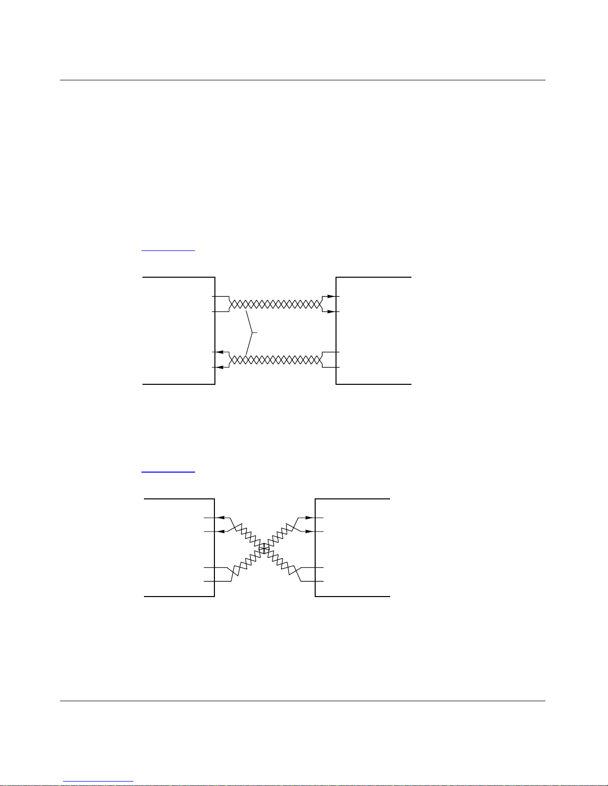
For two de vice s to communicate, the tr ansmi tter of each de vi ce must be connected
to the receiver of the other device. The crossover function is usually implem ented
internally a s par t of the c irc uitry i n the de vi ce. Computer s and w orkstation adapt er
cards are usually media-dependent interface ports, called MD I or uplink ports.
Most hub and switch ports are configured as media-dependent interfaces with
built- in crosso v er ports, call ed MDI-X or normal p ort s. Refer to t he i nstruction s in
Chapter 3, “Installation,” for appropriate cable use and connecti on.
Figure B-1
Transmit
Receive
MDI port MDI-X port
illustrates a straight-through twisted-pair cable.
1
2
Twisted pairs
3
6
1
Receive
2
3
Transmit
6
2008.8
Figure B-1. Straight-Through Twisted-Pair Cable
Figure B-2 illustrates a crossover twisted-pair cable.
Receive
1
2
1
Receive
2
Transmit
MDI-X port MDI-X port
3
6
Figure B-2. Crossover Twisted-Pair Cable
B-2
3
Transmit
6
7666EA
206375-A
Page 55

Numbers
10BA SE-T to 100BASE-T X ne tworks, bridging 2-7
10BASE-T/100BASE-TX ports 1-4
A
applications
bridgi ng from 10BASE-T to 100BASE-TX
networks 2-7
desktop switching 2-3
extending a network 2-6
segment switching 2-4
autonegotiation 1-4
B
bridgi ng from 10BASE-T to 100BASE-TX networks
2-7
button, MDI/MDI-X 1-4
C
cable
10BASE-T connections B-1
crossover and straight-through B-2
crossover tw isted-pair 3-6
strai ght-through twisted-pair 3-6
cable hol der 1-8
connections to other devices 3-5
connectors
10BASE-T/100BASE-TX 1-4, B-1
RJ-45 B-1
crossover twisted-pair cable 3-6, B-2
customer support xv
Index
D
DC power adapter 1-8
desktop switching 2-2, 2-3
E
electrical specifications A-1
electromagnetic susceptibility A-3
environment, operating 3-2
environ mental sp e ci ficatio ns A -2
F
fans 1- 9
featur es 1-9
front panel
BayStack 70-16T 10/100 Ethernet Swi tch 1-3
BayStack 70-24T 10/100 Ethernet Swi tch 1-3
BayStack 70-8T 10/100 Et hernet Switch 1-3
overview 1- 2
full- duplex mode 1-1
H
half-duplex mode 1-1
high-bandwidth file server connections 2-8
I
installation
in a standard equipment rack 3-4
on a flat sur fac e 3-3
verifying 3-7
instal lation, troubleshooting 4-1
206375-A
Index-1
Page 56

L
LEDs
description 3-9
overview 1- 5
M
MDI/MDI-X
button 1-4
cables B-2
pin assi gnm ents B-1
moun ti ng bra cke ts 3-4
N
netwo rk , extend in g 2-6
Normal/Uplink push button 3-6
O
operating environment 3-2
R
rack mounting the BayStack 70-24T 10/100 Ethernet
Switch 3-4
rear panel 1-6
RJ-45 connector pin assignments B-1
S
safety agency approvals A-3
segment switching 2-2, 2-4
site preparation 3-2
stand ar ds comp atibil it y A-1
strai ght-through cable B-2
straight-through twisted-pair cable 3-6
support, Nortel Networks xv
switching technology
desktop switching 2-2, 2-3
segment switching 2-2, 2-4
P
package contents 3-1
physical specifications A-2
pin assi gnm ents, RJ-45 connector B-1
ports
autonegotiation 1-4
Etherne t 10BASE-T/100B A SE-TX 1-4
power ad apter 1-8, 1- 1 1
power co rd re quire m en ts 3-2
power specifications 3-2
power workgroups 2-8
product features 1-9
product support xv
publications
hard co py xiv
T
techni cal publications xiv
technical specifications A-1
techni cal support xv
troubleshooting 4-1
U
uplink port B-2
W
workgroup connections 2-8
Index-2
206375-A
 Loading...