

Page 1

kombk.book Page i Tuesday, June 29, 1999 3:25 PM
Software Release V1.3.0
Part No. 302401-D Rev 00
July 1999
4401 Great America Parkway
Santa Clara, CA 95054
Using the BayStack 450
10/100/1000 Series Switch
Page 2

kombk.book Page ii Tuesday, June 29, 1999 3:25 PM
Copyright © 1999 Nortel Networks
All rights reserved. Printed in the USA. July 1999.
The information in this document is subject to change without notice. The statements, configurations, technical data,
and recommendations in this document are believed to be accurate and reliable, but are presented without express or
implied warranty. Users must take full respo nsibility fo r th e ir app lica tio ns o f any products specified in this document.
The information in this document is proprietary to Nortel Networks NA Inc.
Trademarks
NORTEL NETWORKS is a trademark of Nortel Networks Corporation.
Bay Networks and Optivity are registered trademar ks and Accelar, BayStack, EZ LAN, Optivity Campus, Optivity
Enterprise, StackProbe, and the Bay Networks logo are trademar ks of Nortel Networks NA Inc.
Microsoft, MS, MS-DOS, Win32, Windows, and Windows NT are registered trademarks of Microsoft Corporation.
All other trademarks and registered trademarks are the property of their respective owners.
Statement of Conditions
In the interest of impro vi ng int ern al de sig n, op er ati onal fun ction , a n d/or relia bi lity, Nortel Networks NA Inc. reserves
the right to make changes to the products described in this document without notice.
Nortel Networks NA Inc. does not assume any liability that may occur due to the use or application of the product(s)
or circuit layout(s) described herein.
USA Requirements Only
Federal Communications Commission (FCC) Compliance Notice: Radio Frequency Notice
Note: This equipment has been tested and found to comply with the limits for a Class A digital device, pursuant to
Part 15 of the FCC rules. These limits are designed to provide reasonable protection against harmful in te rference
when the equipment is op erated in a commercial environment. This equipment generates, uses, and can radiat e radio
frequency energy. If it is not in stalled and used in accordance with the instruction manual, it may cause harmful
interference to radio communications. Operation of this equipment in a residential area is likely to cause harmful
interference, in which case users will be required to take whatever measures may be necessary to correct the
interference at their own expense.
European Requirements Only
EN 55 022 Statement
This is to certify th at the No rtel Netw ork s BaySta ck 45 0 switc h is shi elded a gainst the ge neratio n of radio in terfere nce
in accordance with the application of Council Directive 89/336/EEC, Article 4a. Conformity is declared by the
application of EN 55 022 Class A (CISPR 22).
Warning: This is a Class A product. In a domestic environm en t, thi s produ c t may cau se radio in terf ere n ce, in which
case, the user may be required to take ap propriate measures.
Achtung: Dieses ist ein Gerät der Funk störgrenzwertklasse A. In Wohnbereichen könne n bei Betrieb dieses Gerätes
Rundfunkstörungen auftreten, in welchen Fällen der Benutzer für entsprechende Gegenm aßnahmen verantwortlich
ist.
Attention: Ceci est un produit de Classe A. Dans un environnement domestique, ce pr oduit risque de c réer des
interférences radioélectriques, il appartiendra alors à l’utilisateur de prendre les mesures spécifiques appropriées.
ii
302401-D Rev 00
Page 3

kombk.book Page iii Tuesday, June 29, 1999 3:25 PM
EC Declaration of Conformity
This product co nforms (or these prod ucts conform) to the provisions of Council Directive 89/336/EEC and
73/23/EEC. The Declaration of Conformity is available on the Nortel Networks World Wide Web site at
http://libra2.corpwest.baynetworks.com/cgi-bin/ndCGI.exe/DocView/.
Japan/Nippon Requirements Only
Voluntary Control Council for Interference (VCCI) Statement
Voluntary Control Council for Interference (VCCI) Statement
This is a Class A product based on the standard of the Voluntary Control Council for Interference by Information
Tech nology Equipment (VCCI). If this equipment is used in a domestic environment, radio disturbance may arise.
When such trouble occurs, the user may be required to take corrective actions.
Taiwan Requirements
Bureau of Standards, Metrology and Inspection (BSMI) Statement
Canada Requirements Only
Canadian Department of Communications Radio Interference Regulations
This digital apparatus (BaySt ack 450 switch) do es not e xceed th e C lass A limits f or ra dio-noise emissions from di gital
apparatus as set out in the Radio Interference Regulations of the Canadian Department of Communications.
Règlement sur le brouillage radioélectrique du ministère des Communications
Cet appareil numérique (BayStack 450 switch) respecte les limites de bruits radioélectriques visant les appareils
numériques de classe A prescrites dans le Règlement sur le brouilla ge r adioélectrique du ministère des
Communications du Canada.
302401-D Rev 00
iii
Page 4

kombk.book Page iv Tuesday, June 29, 1999 3:25 PM
Nortel Networks NA Inc. Software License Agreement
NOTICE: Please carefully read this license agreement before copying or using the accompanying software or
installing the hardware unit with pre-enabled software (each of which is referred to as “Software” in this Agreement).
BY COPYING OR USING THE SOFTWARE, YOU ACCEPT ALL OF THE TERMS AND CONDITIONS OF
THIS LICENSE AGREEMENT. THE TERMS EXPRESSED IN THIS AGREEMENT ARE THE ONLY TERMS
UNDER WHICH NORTEL NETWORKS WILL PERMIT YOU TO USE THE SOFTWARE. If you do not accept
these terms and conditions, return the product, unused and in the original shipping container, within 30 days of
purchase to obtain a credit for the full purchase price.
1. License Grant. Nortel Networks NA Inc. (“Nortel Networks”) grants the end user of the Software (“Licensee”) a
personal, none xclusive, nontransferable license: a) to u se the Softw are eit her on a single compute r or, if applicable, on
a single authorized device identified by host ID, for which it was originally acquired; b) to copy the Software solely
for backup purposes in support of authorized use of the Software; and c) to u s e and copy the associated user manual
solely in support of aut horized u se of the Soft ware b y L icensee. This lic ense appl ies to the Softw are only and does no t
extend to Nortel Networks Agent software or other Nortel Networks software products. Nortel Networks Agent
software or other Nortel Networks software products are licensed for use under the terms of the applicabl e Nortel
Networks NA Inc. Software License Agreement that accompanies such software and upon payment by the end user of
the applicable license fees for suc h soft ware.
2. Restrictions on use; reservation of rights. The Software and user manuals are protected under copyright laws.
Nortel Networks and/or its licensors retain all title and ownership in both the Software and user manuals, including
any revisions made by Nortel Networks or its licensors. The c opyright notice must be reproduced and included with
any copy of any portion of the Software or user manuals. Licensee may not modify, translate, decompile, disassemble,
use for any competitive analysis, reverse engineer, distribute, or create derivative works from the Software or user
manuals or any copy, in whole or in part. Except as expressly provided in this Agreement, Licensee may not copy or
transfer the Software or user manuals, in whole or in part. The Software and user manuals embody Nortel Networks’
and its licensors’ confidential and proprietary intellectual prop erty. Licensee shall not sublic e nse, assign, or otherwise
disclose to any third party the Software, or any information about the operation, design, performance, or
implementation of the Software and user manuals that is confidential to Nortel Networks and its licensors; however,
Licensee may grant permission to its consultants, subcont ractors, and agents to us e the Software at Licensee’s facility,
provided they have agreed to use the Software only in accordance with the terms of this license.
3. Limited warranty . Nortel Networks warrants each item of Software, as delivered by Nortel Networks and properly
installed and operated on Nortel Networks hardware or other equipment it is originally licensed for, to function
substantially as described in its accompanying user manual during its warranty period, which begins on the date
Software is first shipped to L icensee. If any i tem of Softwa re fails to so f unction during its w arranty period , as the sole
remedy Nortel Networks will at its discretion provide a suitable fix, patch, or workaround for the problem that may be
included in a future Software release. Nortel Networks further warrants to Licensee that the media on which the
Software is provide d will be free from de fects in materials a nd work manship un der normal u se for a period of 90 days
from the date Software is first shipped to Licensee. Nortel Networks will replace defective media at no charge if it is
returned to Nortel Networks during the warranty period alon g with proof of the date of shipment. This warr anty does
not apply if the media has been damaged as a result of accident, misuse, or abuse. The Licensee assumes all
responsibility for selection of the Software to achieve Licensee’s intended results and for the installation, use, and
results obtained from the Software. Nortel Networks does not warrant a) that the functions cont ained in the software
will meet the Licensee’s requirements, b) that the Software will operate in the hardware or software combinations that
the Licensee may select, c) that the operation of the Software will be uninterrupted or error free, or d) that all defects
in the operation of the So ftware will be correcte d. Nortel Netw orks is not obliga ted to remedy an y Software defect that
cannot be reproduced with the latest Softwa re release. These warranties do not apply to the Software if it has been (i)
altered, except by Nortel Networks or in accordance wi th its instructions; (ii) used in conjunction with another
vendor’s product, resulting in the defect; or (iii) damaged by improper environment, abuse, misuse, accident, o r
negligence. THE FOREGOING WARRANTIES AND LIMITATIONS ARE EXCLUSIVE REMEDIES AND ARE
IN LIEU OF ALL OTHER WARRANTIE S EXPRESS OR IMPLIED, INCLUDING WITHOUT LIMITATION ANY
WARRANTY OF MERCHANTABILITY OR FITNESS FOR A PARTICULAR PURP OS E.
iv
302401-D Rev 00
Page 5

kombk.book Page v Tuesday, June 29, 1999 3:25 PM
Licensee is responsible for the secu rity of its own data and information and for maintaining adequate procedure s apart
from the Software to reconstruct lost or altered files, data, or programs.
4. Limitation of liability. IN NO EVENT WILL NOR TEL NETW ORKS OR ITS LICENSOR S BE LIABLE FOR
ANY COST OF SUBSTITUTE PROCUREM ENT; SPECIAL, INDIRECT, INCIDENTAL, OR CONS EQ UENTIAL
DAMAGES; OR ANY DAMAGES RESULTING FROM INACCURATE OR LOST DATA OR LOSS OF USE OR
PROFITS ARISING OUT OF OR IN CONNECTION WITH THE PERFORMANCE OF THE SOFTWARE, EVEN
IF NORTEL NETWORKS HAS BEEN ADVISED OF THE POSSIBILITY OF SUCH DAMAGES. IN NO EVENT
SHALL THE LIABILITY OF NORTEL NETWORKS RELATING TO THE SOFTWARE OR THIS AGREEM ENT
EXCEED THE PRICE PAID TO NORTEL NETWORKS FOR THE SOFTWARE LICENSE.
5. Government Licensees. This provision applies to all Softw are and d ocumentat ion acquire d directly or indirect ly by
or on behalf of the United States Government. The Software and documentation are commercial products, licensed on
the open market at market prices, and were developed entirel y at private expense and without the use of any U.S.
Government funds. The license to the U.S. Government is granted only with restricted rights, and use, duplication, or
disclosure by the U.S. Government is subject to the restrictions set forth in subparagraph (c)(1) of the Commercial
Computer Software––Restric ted Rig hts cla u se of FAR 52.227-19 and th e limita tio ns se t out in this license for civilian
agencies, and su bparagraph (c)(1 )(ii) of the Rights in Technical Data and Computer Software clause of DFARS
252.227-7013, for agencies of the Department of Defense or their successors, whichever is applicable.
6. Use of Software in the European Community. This provision applies to all Software acquired for use within the
European Community. If Licensee uses the Software within a country in the European Community, the Software
Directive enacted by the Council of European Communities Directive dated 14 May, 1991, will apply to the
examination of the Software to facilitate interoperability. Licensee agrees to no tify Nortel Networks of any such
intended examination of the Software and may procure support and assistance from Nortel Networks.
7. Term and termination. This license is effective un til termin ate d; however, all of the restrictions with respe ct to
Nortel Networks’ copyright in the Software and user manuals will cease being effective at the date of expiration of the
Nortel Networks copy right; those restrictions relating to use and dis closure of Nortel Networks’ confidential
information shall continue in effect. Licensee may terminate this license at any time. The license will automatically
terminate if Licensee fails to comply with any of the terms and conditions of the license. Upon termination for any
reason, Licensee will immediately destroy or return to Nortel Networks the Software, user manuals, and all copies.
Nortel Networks is not liable to Licensee for damages in any form solely by reason of the termination of this license.
8. Export and Re-export. Licensee agrees not to export, directly or indirect ly, the Software or related technical data
or information without first obtaining any required export licenses or other governmental approvals. Without limiting
the foregoing, Licensee, on behalf of itself and its subsidiaries and affiliates, agrees that it will not, without first
obtaining all export licenses and approvals required by the U.S. Government: (i) export, re-export, transfer, or divert
any such Software or tech nical data, or any direct product thereof, to any country to which su ch ex ports or re-exports
are restricte d or em b argoed under United States e x po r t con t rol laws and regulations, or to any nation al or re sident of
such restricted or embargoed countries; or (ii) provide the Software or related technical data or information to any
military end user or for any military end use, including the design, development, or production of any chemical,
nuclear, or biological weapons.
9. General. If any provision of this Agreement is held to be invalid or unenforceable by a cour t of competent
jurisdiction, the remainder of the provisions of this Agreement shall remain in full force and effect. This Agreement
will be governed by the laws of the state of California.
Should you have any questions c oncerning this Agreement, contact Nortel Networks, 4401 Great America Parkway,
P.O. Box 58185, Santa Clara, California 95054-8185.
LICENSEE ACKNOWLEDGES THAT LICENSEE HAS READ THIS AGREEMENT, UNDERSTANDS IT, AND
AGREES TO BE BOUND BY ITS TERMS AND CONDITIONS. LICENSEE FURTHER AGREES THAT THIS
AGREEMENT IS THE ENTIRE AND EXCLUSIVE AGREEMENT BETWEEN NORTEL NETWORKS AND
LICENSEE, WHICH SUPERSEDES ALL PRIOR ORAL AND WRITTEN AGREEMENTS AND
COMMUNICATIONS BETWEEN THE PARTIES PERTAINING TO THE SUBJECT MATTER OF THIS
AGREEMENT. NO DIFFERENT OR ADDITIONAL TERMS WILL BE ENFORCEABLE AGAINST NORTEL
NETWORKS UNLESS NORTEL NETWORKS GIVES ITS EXPRESS WRITTEN CONSENT, INCLUDING AN
EXPRESS WAIVER OF THE TERMS OF THIS AGREEMENT.
302401-D Rev 00
v
Page 6

kombk.book Page vi Tuesday, June 29, 1999 3:25 PM
Page 7

kombk.book Page vii Tuesday, June 29, 1999 3:25 PM
Preface
Audience ......................................... ................................ ................................ .................x xi
Organization ...................................................................................................................xxii
Text Con ventions ...........................................................................................................xxiii
Acronyms ........................... .......................... .......................... ......................... ...............xxiii
Related Publications ......................................................................................................xxiv
How to Get Help .............................................................................................................xxv
Contents
Chapter 1
BayStack 450 10/100/1000 Series Switches
Physical Description .......................................................................................................1-1
Front Panel ...............................................................................................................1-2
Comm Port ........................................................................................................1-3
Uplink/Expansion Slot ........................................................................................1-3
Port Connectors .................................................................................................1-3
LED Display Panel .............................................................................................1-5
Back Panel ...............................................................................................................1-8
AC Power Receptacle ........................................................................................1-9
RPSU Connector .............................................................................................1-10
Cascade Module Slot ..................... ...... ....... ...... ....... ...... ...... ....... ...... ....... .......1 -11
Cooling Fans ....................................................................................................1-11
Features ........................................................................................................................ 1-11
IEEE 802.1p Prioritizing .........................................................................................1-14
IEEE 802.1Q VLANs ..............................................................................................1-14
IGMP Snooping Feature ........................................................................................1-15
Flash Memory Storag e .......................... ...... ....... ...... ....... ...................................... .1-1 5
Storage of Switch Software Image ..................................................................1-15
Storage of Configuration Parameters ..............................................................1-15
MultiLink Trunking ....................................... ....... ...................................... ....... ...... .1 -16
302401-D Rev 00
vii
Page 8

kombk.book Page viii Tuesday, June 29, 1999 3:25 PM
Port Mirroring .........................................................................................................1-16
Autosensing and Autonegotiation ...........................................................................1-16
BootP Automatic IP Configuration/MAC Address ...................................................1-17
SNMP MIB Suppor t ..................................... ....... ...... ....... ...... ...... ....... ...... ..............1-18
Configuration and Switch Management .................................................................1-18
Network Configuration ..................................................................................................1-18
Desktop Switch Application ....................................................................................1-19
Segment Switch Application ...................................................................................1-20
High-Density Switc hed Workgroup Application ............... ...... ...... ....... ...... ..............1-21
Fail-Safe Stack Application .....................................................................................1-22
Stack Operation ............................................................................................................1-23
BayStack 400-ST1 Cascade Module .....................................................................1-23
Cascade A Out Connector ...............................................................................1-24
Unit Select Switch ............................................................................................1-24
Cascade A In Connector .................................................................................1-24
Base Unit ................................................................................................................1-25
Initial Installation ..............................................................................................1-25
Stack MAC Address .........................................................................................1-26
Temporary Base Unit .......................................................................................1-26
Removing a Unit from the Stack ......................................................................1-27
Stack Configurations ..............................................................................................1-27
Stack Up Configurations ..................................................................................1-28
Stack Down Configurations .............................................................................1-28
Redundant Cascade Stacking Feature ..................................................................1-30
IEEE 802.1Q VLAN Workgroups ..................................................................................1-32
IEEE 802.1Q Tagging .............................................................................................1-33
VLANs Spanning Multiple Switches .......................................................................1-37
VLANS Spanning Multiple 802.1Q Tagged Switches ......................................1-37
VLANS Spanning Multiple Untagged Switches ...............................................1-38
Shared Servers ......................................................................................................1-40
VLAN Workgroup Summary ...................................................................................1-45
VLAN Configuration Rules .....................................................................................1-47
IGMP Snooping ............................................................................................................1-48
IGMP Snooping Configuration Rules .....................................................................1-52
IEEE 802.1p Prioritizing ...............................................................................................1-53
viii
302401-D Rev 00
Page 9

kombk.book Page ix Tuesday, June 29, 1999 3:25 PM
MultiLink Trunks .... ...... ....... ....................................... ...... ....... ...... ...... ....... ...... ..............1-57
Client/Server Configuration Using MultiLink Trunks ...............................................1-58
Trunk Configuration Screen Examples ...................................................................1-60
Trunk Configuration Screen for Switch S1 .......................................................1-60
Trunk Configuration Screen for Switch S2 .......................................................1-63
Trunk Configuration Screen for Switch S3 .......................................................1-65
Trunk Configuration Screen for Switch S4 .......................................................1-67
Before Configuring Trunks ......................................................................................1-69
MultiLink Trunking Configuratio n Rules ........................... ...... ...... ....... ....................1-69
How the MultiLink Trunk Reacts to Losing Distributed Trunk Members .................1-71
Spanning Tree Considerations for MultiLink Trunks ...............................................1-72
Additional Tips About the MultiLink Trunking Feature ............................................1-75
Port Mirroring (Conversation Steering) .........................................................................1-76
Port-Based Mirroring Configuratio n ....... ...... ....... ...... ....... ...... ...... ...........................1-77
Address-Based Mirroring Configuration .................................................................1-79
Port Mirroring Configuration Rules .........................................................................1-82
Chapter 2
Installing the BayStack 450 Switch
Installation Requirements ...............................................................................................2-1
Installation Procedure .....................................................................................................2-3
Installing the BayStack 450 Switch on a Flat Surface ..............................................2-3
Installing the BayStack 450 Switch in a Rack ..........................................................2-4
Attaching Devices to the BayStack 450 Switch ........................................................2-7
Connecting the 10BASE-T/100BASE-TX Ports .................................................2-8
Connecting Fiber Optic Ports ............................................................................2-9
Console/Comm Port ........................................................................................2-10
Connecting a Terminal to the Console/Comm Port ..........................................2-11
Connecting Power .........................................................................................................2-12
Verifying the Installation ................................................................................................2-14
Verifying the Installation Using the LEDs ...............................................................2-14
Verifying the Installation Using the Self-Test Screen ..............................................2-15
Initial Setup ...................................................................................................................2-17
Standalone Switch Setup .......................................................................................2-17
Stack Setup ............................................................................................................2-20
302401-D Rev 00
ix
Page 10

kombk.book Page x Tuesday, June 29, 1999 3:25 PM
Chapter 3
Using the Console Interface
Accessing the CI Menus and Screens ............................................................................3-1
Using the CI Menus and Screens ...................................................................................3-2
Navigating the CI Menus and Screens .....................................................................3-2
Screen Fields and Descriptions ...............................................................................3-3
Main Menu ......................................................................................................................3-4
IP Configuration/Setup ......................... ....... ...... ....... ...... ....... ...... ...... ....... ......................3-8
Choosing a BootP Request Mode ................................................................................3-10
BootP When Needed .............................................................................................3-10
BootP Always .........................................................................................................3-11
BootP Disabled ......................................................................................................3-11
BootP or Last Address ...........................................................................................3-12
SNMP Configuration .......... ....................................... ...... ....... ...... ...... ....... ...... ..............3-13
System Characteristics ................................ ...... ....... ...... ....... ...... ...... ....... ...... ....... ....... 3 -15
Switch Configuration .....................................................................................................3-18
MAC Address Table ................................................................................................3-20
VLAN Configuration Menu .....................................................................................3-22
VLAN Configuration .........................................................................................3-24
VLAN Port Configuration .................................................................................3-26
VLAN Display by Port ......................................................................................3-29
Traffic Class Configuration ...............................................................................3-30
Port Configuration ..................................................................................................3-32
High Speed Flow Control Configuration .................................................................3-34
Choosing a High Speed Flow Control Mode ..........................................................3-36
Symmetric Mode ..............................................................................................3-36
Asymmetric ........... ............................................. ............................................. .3-3 7
MultiLink Trunk Configuration ............................. ...... ....... ...... ...... ....... ...... ....... ...... .3 -37
MultiLink Trunk Configuration Screen ..............................................................3-39
MultiLink Trunk Utiliz ation Sc re en ................................................ ....................3-41
Port Mirroring Configuration ...................................................................................3-45
Rate Limiting Configuration ....................................................................................3-48
IGMP Configuration ................................................................................................3-51
Port Statistics .........................................................................................................3-54
Console/Comm Port Configuration ...............................................................................3-58
x
302401-D Rev 00
Page 11

kombk.book Page xi Tuesday, June 29, 1999 3:25 PM
Renumber Stack Units ..................................................................................................3-65
Hardware Unit Information ............................................................................................3-67
Spanning Tree Configuration ........................................................................................3-67
Spanning Tree Port Configuration ..........................................................................3-69
Display Spanning Tree Switch Settings ..................................................................3-72
TELNET Configuration .................................................................................................3-75
Software Download .......................................................................................................3-78
Configuration File .........................................................................................................3-82
Display Event Log .........................................................................................................3-85
Excessive Bad Entries ...........................................................................................3-86
Write Threshold ......................................................................................................3-86
Flash Update .. ...... ....... ....................................... ...... ....... ...... ...... ....... ...... ....... ....... 3 -8 7
Reset ............................................................................................................................3-88
Reset to Default Settings ..............................................................................................3-90
Logout ................................ ................... .................... ................... ................... ............. . 3 -93
Chapter 4
Troubleshooting
Interpreting the LEDs .....................................................................................................4-2
Diagnosing and Correcting the Problem ................... ...... ....... ...... ...... ....... ......................4-5
Normal Power-Up Sequence ....................................................................................4-6
Port Connection Problems .......................................................................................4-7
Autonegotiation Modes ......................................................................................4-8
Port Interface .....................................................................................................4-9
Appendix A
Technical Specifications
Environmental .................... ................................ ................................ ............................ A -1
Electrical ......... ................................................................ ............................................... A -1
Physical Dimensions ...................................................................................................... A-2
Performance Specifications ........................................................................................... A-2
Network Protocol and Standards Compatibility ............................................................. A-2
Data Rate ......................................................................................................................A-2
Interface Options ........................................................................................................... A-3
Safety Agency Certification ........................................................................................... A-3
Electromagnetic Emissions ........................................................................................... A-3
302401-D Rev 00
xi
Page 12

kombk.book Page xii Tuesday, June 29, 1999 3:25 PM
Electromagnetic Immunity ............................................................................................. A-3
Declaration of Conformity .............................................................................................. A-4
Appendix B
Gigabit Fiber Optical Characteristics
1000BASE-SX Models .................................................................................................. B-1
Operating Range ..................................................................................................... B-1
Transmit Characteristics .......................................................................................... B-2
Receive Characteristics .......................................................................................... B-3
Worst-Case Power Budget and Penalties ....................... ...... ...... ....... ..................... B-3
1000BASE-LX Models ................................................................................................... B-4
Operating Range ..................................................................................................... B-4
Transmit Characteristics .......................................................................................... B-5
Receive Characteristics .......................................................................................... B-5
Worst-Case Power Budget and Penalties ....................... ...... ...... ....... ..................... B-6
Appendix C
Media Dependent Adapters
10BASE-T/100BASE-TX MDA ......................................................................................C-2
100BASE-FX MDAs .......................................................................................................C-3
1000BASE-SX MDAs ....................................................................................................C-6
M1000BASE-LX MDAs ..................................................................................................C-9
Installing an MDA ......................................... ...... ....................................... ...... ....... ...... C-11
Replacing an MDA with a Different Model ................................................................... C-13
1000BASE-LX Multimode Applications .......................................................................C-13
Appendix D
Quick Steps to Features
Configuring 802.1Q VLANs ...........................................................................................D-2
Configuring MultiLink Trunks ......................................................................................... D-4
Configuring Port Mirroring .............................................................................................D-5
Configuring IGMP Snooping ..........................................................................................D-7
Appendix E
Connectors and Pin Assignments
RJ-45 (10BASE-T/100BASE-TX) Port Connectors .. ...... ....... ...... ...... ....... ...... ....... ...... .. E-1
MDI and MDI-X Devices ................................................................................................ E-2
MDI-X to MDI Cable Connections ........................................................................... E-3
xii
302401-D Rev 00
Page 13

kombk.book Page xiii Tuesday, June 29, 1999 3:25 PM
MDI-X to MDI-X Cable Connections ..................................... ...... ....... ...... ....... ...... .. E-4
DB-9 (RS-232-D) Console/Comm Port Connector ................................... ...... ....... ...... .. E-5
Appendix F
Default Settings
Appendix G
Sample BootP Configuration File
Index
302401-D Rev 00
xiii
Page 14

kombk.book Page xiv Tuesday, June 29, 1999 3:25 PM
Page 15

kombk.book Page xv Tuesday, June 29, 1999 3:25 PM
Figure 1-1. BayStack 450 Switch Versions .................................................................1-1
Figure 1-2. BayStack 450 Switch Front Panels ..........................................................1-2
Figure 1-3. BayStack 450-24T/12T LED Display Panel ..............................................1-5
Figure 1-4. BayStack 450-12F LED Display Panel .....................................................1-6
Figure 1-5. BayStack 450 Switch Back Panel ............................................................1-9
Figure 1-6. BayStack 450 Switch Used as a Desktop Switch ..................................1-19
Figure 1-7. BayStack 450 Switch Used as a Segment Switch .................................1-20
Figure 1-8. Configuring Power Workgroups and a Shared Media Hub ....................1-21
Figure 1-9. Fail-Safe Stack Example ........................................................................1-22
Figure 1-10. BayStack 400-ST1 Front-Panel Components ....... .................................1-23
Figure 1-11. Connecting Cascade Cables .................................................................1-24
Figure 1-12. Stack Up Configuration Example ...........................................................1-28
Figure 1-13. Stack Down Configuration Example .......................................................1-29
Figure 1-14. Redundant Cascade Stacking Feature ..................................................1-31
Figure 1-15. Port-Based VLAN Example ......... ....... ...... ....................................... ...... .1-3 2
Figure 1-16. Default VLAN Settings ...........................................................................1-34
Figure 1-17. 802.1Q Tagging (1 of 4) .........................................................................1-35
Figure 1-18. 802.1Q Tagging (2 of 4) .........................................................................1-35
Figure 1-19. 802.1Q Tagging (3 of 4) .........................................................................1-36
Figure 1-20. 802.1Q Tagging (4 of 4) .........................................................................1-36
Figure 1-21. VLANs Spanning Multiple 802.1Q Tagged Switches .............................1-37
Figure 1-22. VLANs Spanning Multiple Untagged Switches ......................................1-38
Figure 1-23. Possible Problems with VLANs and Spanning Tree Protocol .................1-39
Figure 1-24. Multiple VLANs Sharing Resources .......................................................1-40
Figure 1-25. VLAN Broadcast Domains Within the Switch .........................................1-41
Figure 1-26. Default VLAN Configuration Screen Example ........................................1-42
Figure 1-27. VLAN Configuration Screen Example ....................................................1-43
Figure 1-28. Default VLAN Port Configuration Screen Example ................................1-44
Figure 1-29. VLAN Port Configuration Screen Example ............................................1-45
Figures
302401-D Rev 00
xv
Page 16

kombk.book Page xvi Tuesday, June 29, 1999 3:25 PM
Figure 1-30. VLAN Configuration Spanning Multiple Switches ..................................1-46
Figure 1-31. IP Multicast Propagation With IGMP Routing ........................................1-49
Figure 1-32. BayStack 450 Switch Filtering IP Multicast Streams (1 of 2) .................1-50
Figure 1-33. BayStack 450 Switch Filtering IP Multicast Streams (2 of 2) .................1-51
Figure 1-34. Prioritizing Packets .......................................... ...... ...... ....... ...... ....... ...... .1 -53
Figure 1-35. Port Transmit Queue ..............................................................................1-54
Figure 1-36. Default Traffic Class Configuration Screen Example .............................1-55
Figure 1-37. Setting Port Priority Example .................................................................1-56
Figure 1-38. Switch-to-Switch Trunk Configuration Example .....................................1-57
Figure 1-39. Switch-to-Server Trunk Configuration Example .....................................1-58
Figure 1-40. Client/Server Configuration Example .....................................................1-59
Figure 1-41. Choosing the MultiLink Trunk Configuration Screen ..............................1-60
Figure 1-42. MultiLink Trunk Configuration Screen for Switch S1 ..............................1-61
Figure 1-43. MultiLink Trunk Configuration Screen for Switch S2 ..............................1-63
Figure 1-44. MultiLink Trunk Configuration Screen for Switch S3 ..............................1-65
Figure 1-45. MultiLink Trunk Configuration Screen for Switch S4 ..............................1-67
Figure 1-46. Loss of Distributed Trunk Members .......................................................1-71
Figure 1-47. Path Cost Arbitration Example ...............................................................1-72
Figure 1-48. Example 1: Correctly Configured Trunk .................................................1-73
Figure 1-49. Example 2: Detecting a Misconfigured Port .......... ...... ....... ...... ....... ...... .1 -74
Figure 1-50. Port-Based Mirroring Configuratio n Exampl e .......................... ....... ...... .1-77
Figure 1-51. Port Mirroring Port-Based Screen Example ...........................................1-79
Figure 1-52. Address-Based Mirroring Configuration Example ..................................1-80
Figure 1-53. Port Mirroring Address-Based Screen Example ....................................1-81
Figure 2-1. Package Contents ....................................................................................2-2
Figure 2-2. Positioning the Chassis in the Rack .........................................................2-5
Figure 2-3. Attaching Mounting Brackets ...................................................................2-6
Figure 2-4. Installing the BayStack 450 Switch in an Equipment Rack ......................2-6
Figure 2-5. 10/100 Mb/s Port Connections .................................................................2-8
Figure 2-6. Fiber Optic Port Connections ...................................................................2-9
Figure 2-7. Connecting to the Console/Comm Port .................................................2-11
Figure 2-8. BayStack 450 Switch AC Power Receptacle ..........................................2-13
Figure 2-9. Grounded AC Power Outlet ....................................................................2-13
Figure 2-10. Observing LEDs to Verify Proper Operation ..........................................2-14
Figure 2-11. BayStack 450 Switch Self-Test Screen ..................................................2-15
xvi
302401-D Rev 00
Page 17

kombk.book Page xvii Tuesday, June 29, 1999 3:25 PM
Figure 2-12. Nortel Networks Logo Screen ................................................................2-16
Figure 2-13. Main Menu .............................................................................................2-18
Figure 2-14. IP Configuration/Setup Screen (Standalone Switch) .............................2-19
Figure 2-15. Main Menu (Standalone Switch Example) .............................................2-21
Figure 2-16. Main Menu (Stack Configuration Example) ............................................2-21
Figure 2-17. IP Configuration/Setup Screen (Stack Configuration) ............................2-22
Figure 3-1. Map of Console Interface Screens ...........................................................3-3
Figure 3-2. Console Interface Main Menu ..................................................................3-4
Figure 3-3. IP Configuration/Setup Screen ................................................................3-8
Figure 3-4. SNMP Configuration Screen ....... ....... ...... ....... ...... ...... ....... ...... ....... ...... .3-13
Figure 3-5. System Characteristics Screen .......... ...... ....... ...... ...... ....... ...... ....... ...... .3 -15
Figure 3-6. Switch Configuration Menu Screen ........................................................3-18
Figure 3-7. MAC Address Table Screen ...................................................................3-21
Figure 3-8. VLAN Configuration Menu Screen .........................................................3-23
Figure 3-9. VLAN Configuration Screen ............... ...... ....... ...... ...... ....... ...... ..............3-24
Figure 3-10. VLAN Port Configuration Screen ...........................................................3-27
Figure 3-11. VLAN Display by Port Screen ................................................................3-29
Figure 3-12. Traffic Class Configuration Screen .........................................................3-31
Figure 3-13. Port Configuration Screen (1 of 2) .........................................................3-32
Figure 3-14. Port Configuration Screen (2 of 2) .........................................................3-33
Figure 3-15. High Speed Flow Control Configuration Screen ....................................3-35
Figure 3-16. MultiLink Trunk Configuration Menu Screen ..........................................3-38
Figure 3-17. MultiLink Trunk Configuration Screen ....................................................3-40
Figure 3-18. MultiLink Trunk Utilization Sc reen (1 of 2) ....... ...... ...... ...........................3-42
Figure 3-19. MultiLink Trunk Utilization Sc reen (2 of 2) ....... ...... ...... ...........................3-43
Figure 3-20. Port Mirroring Configuration Screen ......................................................3-45
Figure 3-21. Rate Limiting Configuration Screen (1 of 2) ...........................................3-48
Figure 3-22. Rate Limiting Configuration Screen (2 of 2) ...........................................3-49
Figure 3-23. IGMP Configuration Screen ...................................................................3-51
Figure 3-24. Port Statistics Screen .............................................................................3-54
Figure 3-25. Console/Comm Port Configuration Screen ............................................3-58
Figure 3-26. Renumber Stack Units Screen ...............................................................3-65
Figure 3-27. Hardware Unit Information Screen .........................................................3-67
Figure 3-28. Spanning Tree Configuration Menu Screen ...........................................3-68
Figure 3-29. Spanning Tree Port Configuration Screen (1 of 2) .................................3-69
302401-D Rev 00
xvii
Page 18

kombk.book Page xviii Tuesday, June 29, 1999 3:25 PM
Figure 3-30. Spanning Tree Port Configuration Screen (2 of 2) .................................3-70
Figure 3-31. Spanning Tree Switch Settings Screen ..................................................3-72
Figure 3-32. TELNET Configuration Screen ..............................................................3-75
Figure 3-33. Software Download Screen ...................................................................3-79
Figure 3-34. Configuration File Download/Upload Screen .........................................3-82
Figure 3-35. Event Log Screen .......... ....... ...... ....... ...... ....................................... ...... .3-8 5
Figure 3-36. Sample Event Log Entry Showing Excessive Bad Entries .....................3-86
Figure 3-37. Sample Event Log Entry Exceeding the Write Threshold ......................3-87
Figure 3-38. Sample Event Log Entry Showing Flash Update Status ........................3-87
Figure 3-39. Self-Test Screen After Resetting the Switch ......... ...... ....... ...... ....... ...... .3-8 8
Figure 3-40. Nortel Networks Logo Screen ................................................................3-89
Figure 3-41. Self-Test Screen After Resetting to Default Settings ..............................3-91
Figure 3-42. Nortel Networks Logo Screen After Resetting to Default Settings .........3-92
Figure 3-43. Password Prompt Screen ......................................................................3-93
Figure 4-1. BayStack 450-24T/12T LED Display Panel ..............................................4-2
Figure 4-2. BayStack 450-12F LED Display Panel .....................................................4-3
Figure C-1. 400-4TX MDA Front Panel ......................................................................C-2
Figure C-2. 100BASE-FX MDA Front Panels .............................................................C-4
Figure C-3. 1000BASE-SX MDA Front Panels ..........................................................C-7
Figure C-4. 1000BASE-LX MDA Front Panels .........................................................C-10
Figure C-5. Installing an MDA .................................................................................. C-12
Figure D-1. Configuring 802.1Q VLANs (1 of 2) ........................................................D-2
Figure D-2. Configuring 802.1Q VLANs (2 of 2) ........................................................D-3
Figure D-3. Configuring MultiLink Trunks ...................................................................D-4
Figure D-4. Configuring Port Mirroring (1 of 2) ..........................................................D-5
Figure D-5. Configuring Port Mirroring (2 of 2) ..........................................................D-6
Figure D-6. Configuring IGMP Snooping (1 of 3) ....................................................... D-7
Figure D-7. Configuring IGMP Snooping (2 of 3) ....................................................... D-8
Figure D-8. Configuring IGMP Snooping (3 of 3) ....................................................... D-9
Figure E-1. RJ-45 (8-Pin Modular) Port Connector ................................................... E-1
Figure E-2. MDI-X to MDI Cable Connections ........................................................... E-3
Figure E-3. MDI-X to MDI-X Cable Connections ....................................................... E-4
Figure E-4. DB-9 Console/Comm Port Connector ..................................................... E-5
xviii
302401-D Rev 00
Page 19

kombk.book Page xix Tuesday, June 29, 1999 3:25 PM
Table 1-1. BayStack 450 Switch LED Descriptions .................................................1-6
Table 1-2. International Power Cord Specifications ..................................................1-9
Table 2-1. Power-Up Sequence ..............................................................................2-14
Table 3-1. Console Interface Main Menu options .....................................................3-5
Table 3-2. IP Configuration/Setup Screen Fields .....................................................3-9
Table 3-3. SNMP Configuration Screen Fields ......................................................3-13
Table 3-4. System Characteristics Screen Fields ..................................................3-16
Table 3-5. Switch Configuration Menu Screen Options .........................................3-19
Table 3-6. MAC Address Table Screen Fields .......................................................3-21
Table 3-7. VLAN Configuration Menu Screen Options ...........................................3-23
Table 3-8. VLAN Configuration Screen Fields .......................................................3-25
Table 3-9. VLAN Port Configuration Screen Fields ................................................3-27
Table 3-10. VLAN Display by Port Screen Fields .....................................................3-30
Table 3-11. Traffic Class Configuration Screen Fields ..............................................3-31
Table 3-12. Port Configuration Screen Fields ..........................................................3-33
Table 3-13. High Speed Flow Control Configuration Screen Fields .........................3-35
Table 3-14. MultiLink Trunk Configuration Menu Screen Options .............................3-38
Table 3-15. MultiLink Trunk Configuration Screen Fields .........................................3-40
Table 3-16. MultiLink Trunk Utilization Scre en Fiel ds .......................... ...... ....... ...... .3 -4 3
Table 3-17. Port Mirroring Configuration Screen Fields ...........................................3-46
Table 3-18. Monitoring Modes ..................................................................................3-47
Table 3-19. Rate Limiting Configuration Screen Fields .............................................3-50
Table 3-20. IGMP Configuration Screen Fields .......................................................3-52
Table 3-21. Port Statistics Screen Fields .................................................................3-55
Table 3-22. Console/Comm Port Configuration Screen Fields ................................3-58
Table 3-23. Renumber Stack Units Screen Options ................................................3-66
Table 3-24. Spanning Tree Configuration Menu Screen Options .............................3-68
Table 3-25. Spanning Tree Port Configuration Screen Fields ..................................3-70
Table 3-26. Spanning Tree Switch Settings Parameters ..........................................3-73
Tables
302401-D Rev 00
xix
Page 20

kombk.book Page xx Tuesday, June 29, 1999 3:25 PM
Table 3-27. TELNET Configuration Screen Fields ...................................................3-76
Table 3-28. Software Download Screen Fields ........................................................3-79
Table 3-29. LED Indications During the Software Download Process .....................3-81
Table 3-30. Configuration File Download/Upload Screen Fields .............................3-83
Table 3-31. Parameters Not Saved to the Configuration File ....................................3-84
Table 4-1. BayStack 450 Switch LED Descriptions .................................................4-3
Table 4-2. Corrective Actions ...................................................................................4-7
Table B-1. Operating Range for 1000BASE-SX ....................................................... B-1
Table B-2. 1000BASE-SX Transmit Characteristics ................................................. B-2
Table B-3. 1000BASE-SX Receive Characteristics ................................................. B-3
Table B-4. Worst-Case 1000BASE-SX Power Budget and Penalties ...................... B-4
Table B-5. Operating Range for 1000BASE-LX ....................................................... B-4
Table B-6. 1000BASE-LX Transmit Characteristics ................................................ B-5
Table B-7. 1000BASE-LX Receive Characteristics ................................................. B-5
Table B-8. Worst-Case 1000BASE-LX Power Budget and Penalties ....................... B-6
Table C-1. 400-4TX MDA Components ...................................................................C-2
Table C-2. 100BASE-FX MDA Components ...........................................................C-5
Table C-3. 1000BASE-SX MDA Components .......................................................... C-8
Table C-4. 1000BASE-LX MDA Components ........................................................C-11
Table E-1. RJ-45 Port Connector Pin Assignments ................................................ E-2
Table E-2. DB-9 Console/Comm Port Connector Pin Assignments ........................ E-5
Table F-1. Factory Default Settings for the Ba yStack 450 Switch ............................F-1
xx
302401-D Rev 00
Page 21

kombk.book Page xxi Tuesday, June 29, 1999 3:25 PM
Congratulations on your purchase of the BayStack 450 switch, part of the
Nortel Networks
products.
There are three versions of the BayStack 450 switch: the Model 450-24T, the
Model 450-12T, and the Model 450-12F. This guide describes the features, uses,
and installation procedures for the three versions. (Unless otherwise specified, the
terms “Bay Stack 450 switch” and “switch” refer to all s witch versions.)
Preface
®
BayStack 10/100/1000 Switch line of communications
Audience
BayStack 450 switches include a dedicated Uplink Module slot for attaching
optional media dependent adapters (MDAs) that support a range of media types,
including gigabit Ethernet. Installation instructions are included with each MDA
(see your Nortel Networks sales representa tive for ordering in formation).
For more information about the MDAs, see Appendix C, “Media Dependent
Adapters.”
BayStack 450 switches c onfigured with BayStack 450 softwar e version V1.1.0 or
later provide Fail-Safe stackability when you install the optional BayStack
400-ST1 Cascade Module. Installation instructions are included with each
BayStack 400-ST1 Cascade Module (see your Nortel Networks sales
representative for ordering information).
For more information about the BayStack 400-ST1 Cascade Module, see “Stack
Operation” on page 1-23.
This guide is intended fo r network inst allers and sy stem administrators who are
responsible for installing, configuring, or maintaining networks. This guide
assumes that you und ers ta nd t he t ran smis sion and management protocols used on
your network.
302401-D Rev 00
xxi
Page 22

kombk.book Page xxii Tuesday, June 29, 1999 3:25 PM
Using the BayStack 450 10/100/1000 Series Switch
Organization
This guide has four chapters, seven appendixes, and an index:
If you want to: Go to:
Learn about the BayStack 450 switch and its key features Chapter 1
Install the BayStack 450 switch on a flat surface or in a 19-inch
equipment rack, and verify its operation
Connect to the BayStack 450 switch Console/Comm Port and
learn how to use the console interface (CI) menus to configure
and manage a standalone switch or a stack configuration
Troubleshoot and diagnose problems with the BayStack 450
switch
View operational and environmental specifications that apply to
the BayStack 450 switch
View gigabit fiber optical characteristics of the (optional)
1000BASE-SX/LX MDAs
Learn about optional media dependent adapters (MDAs) you
can use with the BayStack 450 switch
Learn about Quick-Step flowcharts for using the BayStack 450
switch features
Learn more about the BayStack 450 switch connectors (ports)
and pin assignments
Chapter 2
Chapter 3
Chapter 4
Appendix A
Appendix B
Appendix C
Appendix D
Appendix E
View a listing of the factory default settings for the BayStack
450 switch
View a sample BootP configuration file Appendix G
View an alphabetical listing of the topics and subtopics in this
guide, with cross-references to relevant information
xxii
Appendix F
Index
302401-D Rev 00
Page 23

kombk.book Page xxiii Tuesday, June 29, 1999 3:25 PM
Text Conventions
This guide uses the following text conventions:
Preface
bold text
Indicates command names and options and text that
you need to enter.
Example: Enter
Example: Use the
show ip {alerts | routes
dinfo
command.
}.
italic text Indicates fi le and directory names, new term s, book
titles, and variables in command syntax descriptions.
Where a variable is two or more words, th e words are
connected by an underscore.
Example: If the command syntax is:
show at
valid_route
valid_route
<
>
is one variable and you substitute one value
for it.
screen text Indicates system output, for example, prompts and
system m essages.
Example:
Set Trap Monitor Filters
[Enter] Named keys in text are enclosed in square brackets.
The notation [Enter] is used for the Enter key and the
Return key.
[Ctrl]-C Two or more ke ys that must be pressed si mul tan eously
Acrony ms
This guide uses the following acronyms:
AUI attachme nt unit interface
BootP Bootstrap Protocol
CSMA/CD carrier sense multiple access/collision detection
302401-D Rev 00
are shown in text linked with a hyphen (-) sign.
xxiii
Page 24

kombk.book Page xxiv Tuesday, June 29, 1999 3:25 PM
Using the BayStack 450 10/100/1000 Series Switch
IP Internet Protocol
ISO Interna tional Organization for St andardizat ion
MAC media access control
MAU media access unit
MDI-X medium dependent interface cros sover
PPP Point-to-Point Protocol
SNMP Simple Network Management Protocol
STP shielded twisted pai r
Related Publications
For more inf ormat ion about using the BayStack 450 switch, refer to the following
publications:
• Installing Media Dependent Adapters (MDA)s (Bay Networks part number
302403-C)
Describes how to install optional MDAs to your BayStack 450 switch.
• Installing the BayStac k 400-ST1 Cas cade Module (Bay Networks part number
304433-A)
Describes how to connect up to eight BayStack 450 swit ches into a stack
configuration by installing optional BayStack 400-ST1 Cascade Modules.
• Wall Mounting Instructio ns (Bay Networks part number 304602-A)
Describes ho w to mount up to two BaySt ack 350 or BayStack 45 0 switches on
any wall that can safely support the weight of the switches, including any
attached cables.
You can print selected technical manuals and release notes free, directly from the
Internet. Go to support.baynetworks.com/library/tpubs/. Find the product for
which you need documentation. Then locate the specific category and model or
version for your har dwar e or sof twa re pro duct. Usi ng Ad obe Acrob at Reade r, you
can open the manuals and rel ease notes, search for the section s you need, and print
them on most standard printers. You can download Acrobat Reader free from the
Adobe Systems Web site, www.adobe.com.
xxiv
302401-D Rev 00
Page 25

kombk.book Page xxv Tuesday, June 29, 1999 3:25 PM
You can purchase selected documentation sets, CDs, and technical publications
through the collateral catalog. The catalog is located on the World Wide Web at
support.baynetworks.com/catalog.html and is divided into sections arranged
alphabetically:
• The “CD ROMs” section lists available CDs.
• The “Guides/Books” section lists books on technical topics.
• The “Technical Manuals” section lists available printed documentation sets.
How to Get Help
If you purchased a service contract for your Nortel Networks product from a
distributor or authorized reseller, contact the technical support staff for that
distributor or reseller for assistance.
Preface
If you purchased a Nortel Netw orks s ervic e progr am, cont act on e of t he fol lo w ing
Nortel Networks Technical Solutions Centers:
Technical Solutions Center Telephone Number
Billerica, MA 800-2LANWAN (800-252-6926)
Santa Clara, CA 800-2LANWAN (800-252-6926)
Valbonne, France 33-4-92-96-69-68
Sydney, Australia 61-2-9927-8800
Tokyo, Japan 81-3-5402-7041
302401-D Rev 00
xxv
Page 26

kombk.book Page xxvi Tuesday, June 29, 1999 3:25 PM
Page 27
kombk.book Page 1 Tuesday, June 29, 1999 3:25 PM
BayStack 450 10/100/1000 Series Switches
This chapter intr oduces the BayStack 450 switch and covers the following topics:
• Physical description
Chapter 1
• Summary of features
• Network configuration examples
• Overview of ma in features
Physical Description
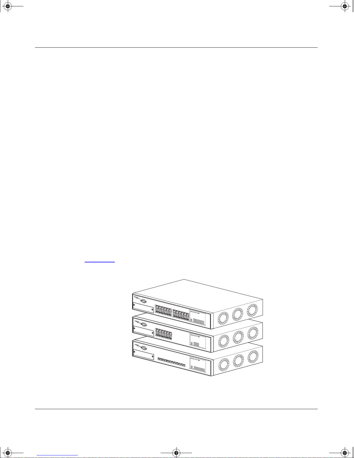
There are three versions of the BayStack 450 switch: the BayStack 450-24T
switch, the BayStack 450-12T switch, and the BayStack 450-12F switch
(Figure 1-1
BayStack 450-24T
BayStack 450-12T
).
BayStack 450-12F
Figure 1-1. BayStack 450 Switch Versions
302401-D Rev 00
BS45001B
1-1
Page 28
kombk.book Page 2 Tuesday, June 29, 1999 3:25 PM
Using the BayStack 450 10/100/1000 Series Switch
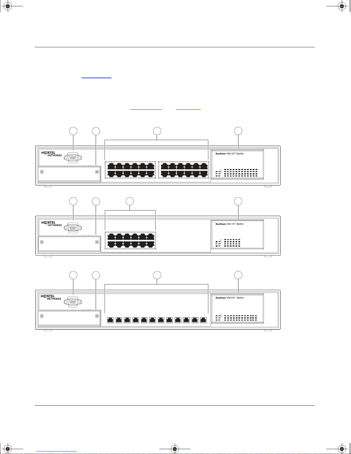
Front Panel
Figure 1-2 shows the fro nt-panel conf igurat ions f or the three Bay Stack 450 switch
models. Descriptions o f the front-panel components follow the figures.
For a description of the components located on the back panel of the BaySta ck
450 switch, see “Back Panel
” on page 1-8.
1
Comm Port
Uplink/Expansion Module
1
Comm Port
Uplink/Expansion Module
1
Comm Port
2
2826 2725
5713 9
682 4 10 12
3
11
17 1913 15 21
18 2014 16 22 24
23
Cas
Pwr Up
Dwn
Status
RPSUBase
4
10/100
Activity
10/100
Activity
BayStack 450-24T
2
16
13 1514
3 4
5713 9
682 4 10 12
11
Cas
Pwr
Up
Dwn
Status
RPSU
Base
10/100
Activity
10/100
Activity
BayStack 450-12T
2
3
4
Uplink/Expansion Module
1
= Comm Port
2
= Uplink/Expansion slot
3
= Port connectors
4
= LED display panel
1614 1513
Figure 1 -2. BayStack 450 Switch Front Panels
1-2
5713 96824 10 1211
BayStack 450-12F
Pwr Up
Status
RPSUBase
Cas
Dwn
Link
F Dx
Activity
BS45002B
302401-D Rev 00
Page 29

kombk.book Page 3 Tuesday, June 29, 1999 3:25 PM
Comm Port
The Comm Port (also referred to as the Console/Comm Port) allows you to access
the console interface (CI) screens and customize your network using the supplied
menus and screens (see Chapter 3, “Using the Console Interface”).
The Console/Comm Port is a DB-9, RS-2 32-D male serial port connector. You can
use this connector to connect a management station or console/terminal to the
switch by using a straight-through DB-9 to DB-9 standard serial port cable (see
“Console/Comm Port” on page 2-10).
BayStack 450 10/100/1000 Series Switches
Note:
The Console/Comm Port is configured as a data communications
equipment (DCE) connector. Ensure that your RS-232 cable pinouts are
configured for DCE connections (see “DB-9 (RS-232-D) Console/ Comm Port
Connector” on page E-5).
The console port default settings are: 9600 baud with eight data bits, one stop bit,
and no parity as the communications format, with flow control set to disabled.
Uplink/Expansion Slot
The Uplink/Expansion slot allows you to attach optional media dependent
adapters (MDAs) that support a range of media types (see Appendix C, “Media
Dependent Adapters” f or more information about MDA types available from
Nortel Networks).
Port Connectors
10BASE-T/1 00BASE-TX Ports
The BayStack 450-24T switch and the BayStack 450-12T switch use
10BASE-T/100BASE-TX RJ-45 (8-pin modular) port connectors.
Note:
The RJ-45 port connectors on BayStack 450 switches manufactured
prior to December 1998 are numbered 1 to 12 and 13 to 24, in succession fr om
left to right. Later units use port conn ectors t hat ar e conf igure d with o ne or tw o
dual, six-port groups, numbered 1 to 12 and 13 to 24. The top rows are odd
numbered and the bottom rows are even numbered (see Figure 1-2
page 1-2
). Port-specific examples in this guide show the appropriate port
connections when required; other examples apply to both versions.
302401-D Rev 00
on
1-3
Page 30

kombk.book Page 4 Tuesday, June 29, 1999 3:25 PM
Using the BayStack 450 10/100/1000 Series Switch
The 10BASE-T/100BASE-TX port connectors are configured as M DI-X
(media-dependen t interface- crossov er). These ports conne ct ove r straight cables to
the network interface controller (NIC) card in a node or server, similar to a
conventional Ethernet repeater hub. If you are connecting to an Ethernet hub or
Ethernet switch, you need a crossover cable unless an MDI connection exists on
the associated port of the attached device (see “MDI and MDI-X Devices” on
page E-2).
The BayStack 450-24T switch and the BayStack 450-12T switch use autosensing
ports that are designed to operate at 10 Mb/s or at 100 Mb/s, depending on the
connecting de vice. Th ese ports support t he IEEE 802.3u a utone gotiati on standar d,
which means that when a port is co nnected t o anoth er de vice t hat a lso suppor ts the
IEEE 802.3u standard, the two devices negotiate the best speed and duplex mode.
The 10BASE-T/100BASE-TX switch ports also support half- and full-duplex
mode operation (see “Connecting the 10BASE-T/100BASE-TX Ports” on
page 2-8).
The 10BASE-T/100BASE-TX RJ-45 ports can connect to 10 Mb/s or 100 Mb/s
Ethernet segments or nodes.
Note: Use only Category 5 copper unshielded twisted pair (UTP) cable
connections when connecting 10BASE-T/100BASE-TX ports.
See Appendix E, “Connectors and Pin Assignments” for more information about
the RJ-45 port connectors.
100BASE-FX MT-RJ Ports
The BayStack 450-12F switch uses longwave 1300 nanometer (nm) MT-RJ port
connectors to atta ch devices over 62.5/125 or 50/125 micron multimode fiber
optic cable.
The BayStack 450-12F switch conforms to the IEEE 802.3u 100BASE-FX
standard and can be used for fiber-based 100 Mb/s connections (2 km/6562 ft
maximum distance) to other compatible Fast Ethernet devices. Single-mode fiber
cable is not supported.
1-4
302401-D Rev 00
Page 31

kombk.book Page 5 Tuesday, June 29, 1999 3:25 PM
LED Display Panel
BayStack 450 10/100/1000 Series Switches
Figure 1-3
panels. Figure 1-4
shows the BayStack 450-24T and BayStack 450-12T LED display
shows the BayStack 450-12F LED displ ay panel. See Table 1-1
for a description of the LEDs.
BayStack
Cas
Pwr Up
Dwn
Status
RPSUBase
450-24T Switch
153
2642220 241814 1612810
BayStack 450-24T
1713 151179
2119 23
10/100
Activity
10/100
Activity
BayStack
Cas
Pwr
Up
Dwn
Status
RPSU
Base
450-12T Switch
153 1179
26412810
10/100
Activity
10/100
Activity
BayStack 450-12T
= Dual color LED
BS45003A
Figure 1-3. BayStack 450-24T/12T LED Display Panel
302401-D Rev 00
1-5
Page 32

kombk.book Page 6 Tuesday, June 29, 1999 3:25 PM
Using the BayStack 450 10/100/1000 Series Switch
BayStack
Cas
Pwr Up
Dwn
Status
RPSUBase
= Dual color LED
450-12F Switch
153
BayStack 450-12F
Figure 1-4. BayStack 450-12F LED Display Panel
Table 1-1. BayStack 450 Switch LED Descriptions
Label Type Color State Meaning
117926412810
Link
F Dx
Activity
BS45071A
Pwr Power status Green On DC power is available to the switch’s internal circuitry.
Off No AC power to switch or power supply failed.
Status System status Green On Self-test passed successfully and switch is operational.
Blinking A nonfatal error occurred during the self-test.
Off The switch failed the self-test.
RPSU RPSU status Green On The switch is connected to the HRPSU and can receive
power if needed.
Off The switch is not connected to the HRPSU or HRPSU is
not supplying power.
CAS Up Stack mode Off The switch is in standalone mode.
Green On The switch is connected to the
upstream
unit’s Cascade A
In connector.
Amber On The Cascade A Out connector (CAS Up) for this switch is
looped internally (wrapped to the secondary ring).
(continued)
1-6
302401-D Rev 00
Page 33

kombk.book Page 7 Tuesday, June 29, 1999 3:25 PM
BayStack 450 10/100/1000 Series Switches
Table 1-1. BayStack 450 Switch LED Descriptions
Label Type Color State Meaning
Amber
or
Green
CAS Dwn Stack mode Off The switch is in standalone mode.
Green On The switch is connected to the
Amber On The Cascade A In connector (CAS Dwn) f or th is switch is
Amber
or
Green
Base Base mode Green On The switch is configured as the stack base unit.
Amber On This unit is operating as the stack configuration’s
Blinking Incompatible software revision or unable to obtain a unit
ID (Renumber Stack Unit table full). The unit is on the ring
but cannot participate in the stack configuration.
Cascade A Out connector.
looped internally (wrapped to the secondary ring).
Blinking Incompatible software revision or unable to obtain a unit
ID (Renumber Stack Unit table full). The unit is on the ring
but cannot participate in the stack configuration.
Off The switch is
in standalone mode).
Blinking Stack configuration error: indicates that
units or
temporary base unit
if the base unit (directly downstream from this unit) fails.
(continued)
downstream
configured as the stack base unit (or is
not
multiple
base units are configured in the stack.
no
. This condition occurs automatically
unit’s
base
302401-D Rev 00
If this happens, the following events take place:
• The two units directly upstream and directly
downstream from the failed unit automatically wrap
their cascade connectors and indicate this condition
by lighting their Cas Up and Cas Dwn LEDs (see Cas
Up and Cas Dw n description in this table).
• If the temporary base unit fails, the next unit directly
downstream from this unit becomes the new
temporary base unit. This process can continue until
there are only two units left in the stack configuration.
This automatic failover is a temporary safeguard only. If
the stack configuration loses power, the temporary base
unit will not power up as the base unit when power is
restored. For this reason, you should always assign the
temporary base unit as the base unit (set the Unit Select
switch to Ba se ) u nti l t he failed unit is repaired o r re pla ce d.
(continued)
1-7
Page 34

kombk.book Page 8 Tuesday, June 29, 1999 3:25 PM
Using the BayStack 450 10/100/1000 Series Switch
Table 1-1. BayStack 450 Switch LED Descriptions
Label Type Color State Meaning
10/100 10/100 Mb/s
port speed
indicator
Link Link status Green On BayStack 450-12F model only: valid communications link
F Dx Duplex status Green On BayStack 450-12F model only: the corresponding port is
Green On The corresponding port is set to operate at 1 00 M b/s an d
the link is good.
Green Blinking The corresponding port has been disabled by software.
Amber On The corresponding port is set to operate at 10 Mb/s and
the link is good.
Amber Blinking The corresponding port has been disabled by software.
Off The link connection is bad or there is no connection to
this port.
established.
Off The communications l in k co nne ction is bad or there is no
connection to this port.
Blinking The corresponding port is management disabled.
in full-duplex mode.
(continued)
Activity Port activity Green
or
Amber
Back Panel
The BayStack 450 switch back -panel component s (Figure 1-5) are the same for all
switch versions.
Descriptions of the back-panel components follow the figure.
Off The corresponding port is in half-duplex mode
Blinking Indicates network activity for the corresponding port. A
high level of network activity can cause the LEDs to
appear to be on continuously.
1-8
302401-D Rev 00
Page 35

228FA
kombk.book Page 9 Tuesday, June 29, 1999 3:25 PM
BayStack 450 10/100/1000 Series Switches
1
= AC power receptacle
2
= RPSU connector
3
= Cascade Module Slot
Figure 1-5. BayStack 450 Switch Back Panel
AC Power Receptacle
The AC power receptacle accepts the AC power cord (supplied). For installati on
outside of North Ameri ca, mak e sure that you ha ve t he proper p owe r cord for your
region. Any cord used must have a CEE-22 standard V female connector on one
end and must meet the IEC 320-030 specifications. Table 1-2
for international power cords:
1
100-240V
47-63Hz~
Redundant Power
2
3
Cascade Module
BS45004A
lists specifi cations
302401-D Rev 00
Table 1-2. International Power Cord Specifications
Country/Plug description Specifications Typical plug
Continental Europe:
• CEE7 standard VII male plug
• Harmonized cord (HAR marking
on t he outside of the cord ja cket
to comply with the CENELEC
Harmonized Document HD-21)
220 or 230 VAC
50 Hz
Single phase
(continued)
1-9
Page 36

kombk.book Page 10 Tuesday, June 29, 1999 3:25 PM
Using the BayStack 450 10/100/1000 Series Switch
Table 1-2. International Power Cord Specifications
Country/Plug description Specifications Typical plug
U.S./Canada/Japan:
• NEMA5-15P male plug
• UL recognized (UL stamped
on cord jacket)
• CSA certified (CSA label
secured to the cord)
United Kingdom:
• BS1363 male plug with fuse
• Harmonized cord
Australia:
• AS3112-1981 Male plug
100 or 120 VAC
50–60 Hz
Single phase
227FA
240 VAC
50 Hz
Single phase
229FA
240 VAC
50 Hz
Single phase
230FA
1-10
RPSU Connector
The RPSU connector allows you to connect a backup power supply unit to the
switch. Nortel Networks provides an (optional) high-power redundant power
supply unit (HRPSU) for this purpose. The HRPSU is a hot-swappable power
supply unit that provides uninterrupted operation to up to four BayStack 450
switches in the event that any of the switch power supplies fail.
Nortel Networks provides the HRPSU power rack (Order No. AA0002001) with
four slots for power supply modules (Order No. AA0005003). Each HRPSU can
support up to four BayStack 450 switches. Installation instructions are provided
with the HRPSU.
Contact your Norte l Netw or ks sal es re pre senta tive for more informatio n ab out th e
HRPSU.
302401-D Rev 00
Page 37

kombk.book Page 11 Tuesday, June 29, 1999 3:25 PM
Cascade Module Slot
The Cascade Module slot allows you to attach an optional BayStack 400-ST1
Cascade Module to the switch (see “
You can connect up to eight BayStack 450 switches into a redundant stack
configu ration. Bay Stack 450 s witches use a f ail-sa fe cascad e stac king arch itectur e
which, in the unlikely event of a switch failure, ma intains the in tegrity of the
remaining stack: all signals are looped back at the point of failure. Because each
unit in the stack has a full copy of the stack configuration, operation of the stack
continues without affecting application connectivity.
Any mix of up to eight BayStack 450 switches and BayStack 410-24T switches
can be stacked to provide a total of 224 ports (when all MDA sl ots are configur ed
with the maximum port availability).
BayStack 450 10/100/1000 Series Switches
Stack Operation” on page 1-23).
Features
Installation instructions are provided with each BayStack 400-ST1 Cascade
Module (see Installing the BayStack 400-ST1 Cascade M odule).
See your Nortel Networks sales representative for ordering information.
Cooling Fans
The variable-speed cooling fans (not shown) are located on one side of the
BayStack 450 switch to provide cooling for the internal components. When you
install the switch, be sure to allow enough space on both sides of the switch for
adequate air flow.
BayStack 450 switches provide wire-speed switching that allows
high-performance, low-cost connections to full -duplex and half-duplex
10/100/1000 Mb/s Ethernet local area networks (LANs).
BayStack 450 switches offer the following features:
• High-speed forwarding rate: up to 3 million packets per second (peak)
• Store-and-forward switch: Full-performa nce forwardin g at full line speed,
using a 2.56 Gigabit/second switch fabric
• Learning rate: 3 million addresses per second (peak)
302401-D Rev 00
1-11
Page 38

kombk.book Page 12 Tuesday, June 29, 1999 3:25 PM
Using the BayStack 450 10/100/1000 Series Switch
• Address database size: 16,000 entries at line rate (32,000 entries without
flooding)
• Fail-Safe Stacking: provides uninterrupted connectivity for up to eight units,
with up to 224 ports stacked together as one managed unit (requires one
optional BayStack 400-ST1 Cascade Module kit per stacked unit. See your
Nortel Networks sales represent ative for ordering i nformation).
• Spanning Tree Protocol (STP): complies with IEEE 802.1D standard. STP
can be disabled on the entire switch or stack, or on a per-port basis.
• SNMP agent support for the following managem ent information bases
(MIBs):
-- Bridge MIB (RFC 1493)
-- Ethernet MIB (RFC 1643)
-- RMON MIB (RFC 1757)
-- MIB-II (RFC 1213)
-- Interface MIB (RFC 1573)
-- Nortel Networks proprietary MIBs:
- s5Chas MIB
- s5Agent MIB
- Rapid City MIB
• High-speed uplink/expansion slot: allows you to attach optional media
dependent adapters (MDAs) that support a range of media types.
• Rate limiting: Adjustable broadcast or IP Multicast pa cket-rate limits for
control of broadcast and IP Multicast storms
• Console/Comm port: Allows you to configure and manage the switch locally
or remotely.
• IEEE 802.1Q port-based virtual LANs (VLANs)
• IGMP snooping
• IEEE 802.1p prioritizing
• Upgradeable device firmware in nonvolatile flash memory using the Trivial
File Transfer Protocol (TFTP)
1-12
302401-D Rev 00
Page 39

kombk.book Page 13 Tuesday, June 29, 1999 3:25 PM
• TELNET:
-- Support for up to four simultaneous TELNET sessions
-- Optional password protection
-- Login time-out
-- Failed-login guard
-- Inactivity time-out
-- Allowed source addresses
-- Event logging
• IEEE 802.3u-compliant autonegotiation ports, with four modes:
-- 10BASE-T half-duplex
BayStack 450 10/100/1000 Series Switches
-- 10BASE-T full-duplex
-- 100BA SE-TX half-duplex
-- 100BA SE-TX full-duplex
• Front-panel light emitting diodes (LEDs) to monitor the following:
-- Power status
-- System status
-- Stack status for the following:
- Cascade Up and Cascade Down status
- Base unit status
-- RPSU status
-- Per-port status for the following:
- 1000 Mb/s link
- 100 Mb/s link
- 10 Mb/s link
- Half- and f ull-duplex tran smission
- Tx/Rx activity
- Management enable/disable
302401-D Rev 00
1-13
Page 40

kombk.book Page 14 Tuesday, June 29, 1999 3:25 PM
Using the BayStack 450 10/100/1000 Series Switch
• MultiLink Trunking, supporting:
-- Switch-t o-switch tru nks
-- Switch-t o-server trunks
• Port mirroring (conversation steering)
-- Port-based
-- MAC address-based
• Configuration file download/upload support: allows you to store your switch/
stack configuration parameters on a TFTP server.
• Remote monitoring (RMON), with four groups integrated:
-- Statistics
-- History
-- Alarms
-- Events
IEEE 802.1p Prioritizing
The BayStack 450 swi tc h can prioritize the order in whic h packets are forwarded,
on a per-port basis.
For more information about the 802.1p prioritizing feature, see “
Prioritizing” on page 1-53.
IEEE 802.1Q VLANs
BayStack 450 switches support up to 64 port-based VLANs with IEEE 802.1Q
tagging available per port. When a switch port is configured to be a member of a
VLAN, it is added to a group of ports (workgroup) that belong to one broadcast
domain. You can assign different ports (and t heref ore the devices attached to t hese
ports) to different broadcast domains. This feature allows network flexibility
because you can reassign VLANs to accommodat e network mov es, additions , and
changes, eliminating the need to change physical cabling. For more information
about 802.1Q VLANs, see “
IEEE 802.1p
IEEE 802.1Q VLAN Workgroups” on page 1-32.
1-14
302401-D Rev 00
Page 41

kombk.book Page 15 Tuesday, June 29, 1999 3:25 PM
IGMP Snooping Feature
For conserving bandwidth and controlling IP Multicast, the IGMP snooping
feature can provide the same benefit as IP Multicast routers, but in the local area.
BayStack 450 10/100/1000 Series Switches
For more inf ormation about th e IGMP snooping feature, see “
page 1-48
.
Flash Memory Storage
Storage of Switch Software Image
The BayStack 450 switch uses flash memory to store the switch software image.
The flash memory allows you to update the software image with a newer version
without changing the switch hardware (see “Software Download” on page 3-78).
An in-band connection between the switch and the TFTP load host is required to
download the software image.
If a BootP server is set up properly on the network and the BayStack 450 switch
detects a corrupted software image during the self-test, the switch automatically
uses TFTP to download a new so ftware image.
Storage of Configuration Parameters
Certain configuration parameters, including the system characteristics strings,
some VLAN pa rameters, IGMP c onfiguration parame ters, and the MultiLink
Trunk names are stored in flash memory. These parameters are updated every 10
minutes or whenever a reset command is executed.
IGMP Snooping” on
Note:
Do not power off the switch within 10 minutes of changing any
configuration parameters. Powering down the switch within 10 minutes of
changing configuration parameters can cause the changed configuration
parameters to be lost.
302401-D Rev 00
1-15
Page 42

kombk.book Page 16 Tuesday, June 29, 1999 3:25 PM
Using the BayStack 450 10/100/1000 Series Switch
MultiLink Trunking
The MultiLink Trunking feature allows you to group multiple ports (up to four)
together when forming a link to another switch or server, thus increasing
aggregate thr oughput of the interconnection between two devices, up to 800 Mb/ s
in full-duplex mode. BayStack 450 switches can be configured with up to six
MultiLink Trunks. The trunk members can be configured within a single unit in
the stack or distributed between any of the units within the stack configuration
(distributed trunking).
For more information about the MultiLink Trunking feature, see “MultiLink
Trunks” on page 1-57.
Port Mirroring
The port mirroring fea ture (sometim es referred to as con ver satio n ste ering) allows
you to designate a single switch port as a traffic monitor for up to two specified
ports or two media access control (MAC) addresses. You can specify port-based
monitoring, where all traffic on specified ports is monitored, or address-based
monitoring, where traffic between specified MAC addresses is monitored. You
can attach a probe de vice (such as a Nor tel Network s StackProbe, or equ iv alent) to
the designated monitor port.
For more information about the port mirroring feature, see “Port Mi rroring
(Conversation Steering)” on page 1-76.
Autosensing and Autonegotiation
BayStack 450 switches are autosensing and autonegotiating devices:
• The term autosense refers to a port’s ability to sense the speed of an attached
device.
• The term autonegoti ation refers to a standard ize d protoco l (IEEE 802 .3u) t hat
exists between two IEEE 802.3u-capable devices. Autonegotiation allows the
BayStack 450 switch to select the best of both speed and duplex modes.
Autosensing is used when the attached de vic e i s not capable of autonegotiation or
is using a form of autonegotiation that is not compatible with the IEEE 802.3u
autonegotiation standard. In this case, because it is not possible to sense the
duplex mode of the attached device, the BayStack 450 switch reverts to
half-duplex mode.
1-16
302401-D Rev 00
Page 43

kombk.book Page 17 Tuesday, June 29, 1999 3:25 PM
When autonegotiation-capable devices are attached to the BayStack 450 switch,
the switch ports negotiate down from 100 Mb/s speed and full-duplex mode until
the attached device acknowledges a supported speed and duplex mode.
For more information about autose nsing and autonegotiation modes, see
“Autonegotiation Modes” on page 4-8.
BootP Automatic IP Configuration/MAC Address
The BayStack 450 switc h has a unique 48-bit hardware address, or MAC address,
that is printed on a label on the back panel. You use this MAC address when you
configure the network BootP server to recognize the BayStack 450 switch BootP
requests. A properly configured BootP server enables the switch to automatically
learn its assigned I P address, su bnet mask, IP ad dress o f the defau lt route r (def ault
gateway), and software image file name.
BayStack 450 10/100/1000 Series Switches
When the switch is participating in a stack configuration, a Stack MAC address is
automatically assigned during the stack initialization. The base unit’s MAC
address, with a software offset, is used for the Stack MAC address.
For example, if the base unit’s MAC address is:
00-00-82-99-44-00
and the Stack software offset is:
1F
then the Stack MAC address becomes:
00-00-82-99-44-1F
If another unit in the stack is assigned as the base unit, the MAC address of the
new base unit (with offset) now applies to the stack configuration. The original
stack IP address st ill applies to the new base unit.
For an example of a BootP configuration file, see Appendix G, “Sample BootP
Configurat ion Fil e.”
302401-D Rev 00
1-17
Page 44

kombk.book Page 18 Tuesday, June 29, 1999 3:25 PM
Using the BayStack 450 10/100/1000 Series Switch
SNMP MIB Support
The BayStack 450 switch supports an SNMP agent with industry standard MIBs,
as well as private MIB extensions, which ensures compatibility with existing
network management tools. The BayStack 450 switch supports the MIB-II
(RFC 1213), Bridge MIB (RFC 1493), and the RMON MIB (RFC 1757), which
provide access to detailed management statistics. With SNMP management, you
can configure SNMP traps (on individual ports) to generate automatically for
conditions such as an unauthori zed access attempt or chan ges in a por t’s operating
status. For a complete listing of supported MIBs, see “
Configuration and Switch Management
The BayStack 450 switch is shipped directly from the factory ready to operate in
any 10BASE-T or 100BASE-TX standard network. You can manage the switch
using the Nortel Networks Optivity
generic SNMP-based network management software; however, you must assign
an IP address to the switc h or stac k, dependi ng on the mode of operati on. You can
set both addresses by using the Console/Comm Port or BootP, which resides on
the switch.
Features” on page 1-11.
®
network management software or any
For more information about using the Console/Comm Port to configure the
switch, see Chapter 3, “Using the Console Interface.”
Network Configuration
You can use BayStack 450 switches to connect workstations, personal computers
(PCs), and ser vers to ea ch other by c onnecti ng these de vices d irectly to t he switch ,
through a share d media hub t hat is conn ected to t he swit ch, or b y creat ing a virt ual
LAN (VLAN) through the switch.
This section provides four network configuration examples using BayStack 450
switches:
• Desktop switch application
• Segment switch application
• High-density switched workgroup application
• Fail-safe stack applic ation
1-18
302401-D Rev 00
Page 45

kombk.book Page 19 Tuesday, June 29, 1999 3:25 PM
BayStack 450 10/100/1000 Series Switches
Note:
All models of the BayStack 450 switch can be used interchangeably in
the following network configuration examples.
Desktop Switch Application
Figure 1-6 shows a BayStack 450-24T switch used as a desktop switch, where
desktop workstations are connected directly to switch ports.
This configuration provides dedicated 100 Mb/s connections to the network
center, to the server, and up to 26 users. This configuration uses the optional
400-4TX MDA (10BASE-T/100BASE-TX MDA).
Before After
10BASE-T hub
BayStack 450-24T switch
Server Up to 22 users
To
Network
Center
Key
10 Mb/s
100 Mb/s
200 Mb/s
- 22 users share 10 Mb/s (10/22 Mb/s per user)
- Server bottleneck (10 Mb/s bandwidth)
- Network center bottleneck (10 Mb/s bandwidth)
Network
Center
- 26 users; each with dedicated 100 Mb/s bandwidth
- Server with dedicated 100 Mb/s bandwidth
- Network center with dedicated 100 Mb/s full-duplex
bandwith (200 mb/s bidirectional)
Server Up to 26 users
To
Figure 1-6. BayStack 450 Switch Used as a Desktop Switch
302401-D Rev 00
BS45005A
1-19
Page 46

kombk.book Page 20 Tuesday, June 29, 1999 3:25 PM
Using the BayStack 450 10/100/1000 Series Switch
Segment Switch Application
Figure 1-7 shows a BayStack 450-24T switch used as a segment switch to
alleviat e user contention for bandwidth and eliminate server and network
bottlenecks. Befo re segmentation, 88 users had a total bandwidth of only 10 Mb /s
available. After segmentation, 92 users have 40 Mb/s, four times the previous
bandwidth, while adding 22 dedicated 100 Mb/s connections. This configuration
can be extended to add more segments without degrading performance.
Key
Server
To
Network
Center
Before
10BASE-T hubs
Up to
88 users
BayStack 450-24T
switch
To
Network
Center
After
Server
Up to 22
users
Up to 23
users
Up to 23
users
Up to 23
users
Up to 23
users
10 Mb/s
100 Mb/s
200 Mb/s
- 88 users share 10 Mb/s (10/88 Mb/s per user)
- Server bottleneck (10 Mb/s bandwidth)
- Network center bottleneck (10 Mb/s bandwidth)
-Total of 88 users
Figure 1-7. BayStack 450 Switch Used as a Segment Switch
1-20
- Four sets of 23 users; each set shares 10 Mb/s
(10/23 Mb/s per user)
- Addition of 22 users; each with dedicated
100 Mb/s bandwidth
- Server with dedicated 100 Mb/s bandwidth
- Network center with dedicated 100 Mb/s full-duplex bandwidth
(200 Mb/s bidirectional)
- Total of 114 users
BS45006A
302401-D Rev 00
Page 47

kombk.book Page 21 Tuesday, June 29, 1999 3:25 PM
High-Density Switched Workgroup Application
Figure 1-8 shows an example of using a BayStack 450 switch with a high-speed
(gigabit) connection to a Nortel Networks Accelar
and 304 switches are also shown in this example of a high-density switched
workgroup.
BayStack 450 10/100/1000 Series Switches
™
1100 switch. BayStack 303
As shown in Figure 1-8
connecting to the BayStack 450 switch with an optional gigabit (1000BASE-SX)
MDA for maximum bandwidth. The BayStack 303 and 304 switches have 100
Mb/s connections to the BayStack 450 switch, a 100BASE-TX hub, and a 100
Mb/s server and 10 Mb/s connections to DTE (data terminal equipment).
See the Nortel Networks library Web page: support.baynetworks.com/library/ for
online documentation about the Nortel Networks Accelar 1100 switch and the
BayStack 303 and 304 switches.
BayStack 450-24T
switch
F
, the Accelar 1100 switch is used as a backbone switch,
BayStack 303
switch
CPUPS1 PS2FAN
Accelar 1100 switch
Key
Server
10 Mb/s
100 Mb/s
1000 Mb/s
(Gigabit)
Figure 1-8. Configuring Power Workgroups and a Shared Media Hub
302401-D Rev 00
F
100BASE-TX
hub
BayStack 304
switch
BS45007A
1-21
Page 48

kombk.book Page 22 Tuesday, June 29, 1999 3:25 PM
Using the BayStack 450 10/100/1000 Series Switch
Fail-Safe Stack Application
Figure 1-9 shows an example of eight BayStack 450 switches that are stacked
together as a single managed unit. If any single unit in the stack fails, the
remaining stack remains operational, without interruption.
CPUPS1 PS2FAN
Accelar switch
As shown in Figure 1-9
, the Accelar 1100 switch is used as a backbone switch,
connecting to the BayStack 450 switch with an optional gigabit (1000BASE-SX)
MDA for maximum bandwidth. This configuration uses optional BayStack
400-ST1 Cascade Modules to connect the switches in the fail-safe stack.
For an overview of the fail-safe stacking feature that is available for the BayStack
450 switches, see “
F
Stack Operation” following this section.
BayStack 450-24T switches
Up to
24 users
Up to
28 users
Up to
28 users
Up to
28 users
Up to
28 users
Key
100 Mb/s
1000 Mb/s
Figure 1-9. Fail-Safe Stack Example
1-22
Up to
28 users
Up to
28 users
Up to
28 users
BS45008A
302401-D Rev 00
Page 49

kombk.book Page 23 Tuesday, June 29, 1999 3:25 PM
Stack Operation
BayStack 450 switches that are configured with BayStack 450 software version
V1.1.0 or later provide fail-safe stackabilit y when you install the optional
BayStack 400-ST1 Cascade Module. You can connect up to eight switches to
provide uninterrupted connectivity for up to 224 ports (see “
Application” on page 1-22). The entire stack is manageable as a single unit.
Installation i nstruction s are pro vided wit h the BaySta ck 400-ST1 Casc ade Module
(see your Nortel Networks sales representa tive for ordering in formation).
BayStack 400-ST1 Cascade Module
BayStack 450 10/100/1000 Series Switches
Fail-Safe Stack
Note:
The BayStack 400-ST1 Cascade Module will not operate with
BayStack 450 switches that are configured with BayStack 450 software
versions earlier than version V1.1.0.
If you need to upgrade your BayStack 450 switches, refer to the upgrade
instructions provided in the Installing the BayStack 400-ST1 Cascade Module
guide. You must upgrade the switch before installing the B ayStack 400-ST1
Cascade Module. The front-panel components of the BayStack 400-ST1 Cascade
Module are shown in Figure 1-10
1
Cascade A Out
2
Unit Select
3
Base
.Component descriptions follow the figure.
Cascade A In
4
1 = Blank connectors (unused)
2 = Cascade A Out connector
3 = Unit Select switch
4 = Cascade A In connector
Figure 1-10. BayStack 400-ST1 Front-Panel Components
302401-D Rev 00
BS0031B
1-23
Page 50

kombk.book Page 24 Tuesday, June 29, 1999 3:25 PM
Using the BayStack 450 10/100/1000 Series Switch
Cascade A Out Connector
Provides an attachment point for connecting this unit to another unit via the
cascade cable. A return cable from another unit’ s Cascade A Out connector to th is
unit’s Cascade A In connector completes the stack connection (see the example
shown in Figure 1-11
Unit Select Switch
The Unit Select switch (up = Base) de termines the base unit for the stack
configuration (see “
displayed on t he BayStack 450 LED di splay pan el. Wh en the Unit Select switch is
in the Base (up) position, all other Unit Select switches in the stack configuration
must be set to Off (down).
).
Base Unit” on page 1-25). The Unit Select swit ch status is
Cascade A In Connector
Provides an attachment point for accepting a cascade cable connection from an
adjacent uni t in t he stac k. A return cable from this unit’s Cascade A Out conn ector
to the adjac ent u n it ’s Cascade A In con n ec tor completes the stack connection (see
Cascade A Out
Cascade A Out
).
Cascade A In
1
Cascade A InUnit Select
Cascade A InUnit Select
the example shown in Figure 1-11
Cascade A Out
Unit 1
Unit 2
1 = Base unit
2 = 303978-A cascade cable
3 = 303978-A cascade cable (used for return)
Figure 1-11. Connecting Cascade Cables
1-24
32
BS0032B
302401-D Rev 00
Page 51

kombk.book Page 25 Tuesday, June 29, 1999 3:25 PM
BayStack 450 10/100/1000 Series Switches
Base Unit
Note:
For stacking t hr ee o r mor e units (maximum 8 units per stack), order the
optional 1 meter (39.27 inch) cascade max-return cable (Bay Networks Order
No. AL2018001).
The base unit is the unique stack unit that you configure with the Unit Select
switch on the front panel of the 400-ST1 cascade module. One unit in the stack
must be configured as the base unit; all other units in the stack must have their
Unit Select switch set to Off (see “
Unit Select Switch” on page 1-24). You can
assign any single unit in the stack as the base unit.
Note:
Although you can assign any single unit in the stack as the base unit,
when mixing supported BaySta ck switch models in a single stack, Nortel
Networks recommends that you select the unit with the highest bandwidth to
be the base unit. The additional workload of the base unit is optimized by
using the higher bandwidth switch model.
The physical ordering of all of the other units in the stack is determined by the
position of the base unit within the stack. This is important for management
applications that view the physical ordering of the units within the stack.
302401-D Rev 00
Some characteristics of the base unit are described in the following sections.
Initial Insta l la ti o n
During the initial installat ion of the stack, the softwar e automatically determines
the physical order of al l units i n the stac k accord ing to the position of the base unit
within the stack. Thereafter, the individual units maintain their original unit
numbering, even if you change the position of one or more units in the stack (you
can renumber the units using the Renumber Stack Units screen; see “Renumber
Stack Units” on page 3-65).
For example, when you initially power up the stack, the base unit becomes unit 1
and the unit that the base unit connects to (via the Cascade A Out cable) becomes
unit 2 (and the next unit is unit 3 and so on), until the maximum stack
configu ratio n (up to 8 u nit s) i s rea ched. I f you cha nge t he bas e un it t o anot her un it
in the stack, the new base unit keeps its original unit number in the stack.
1-25
Page 52

kombk.book Page 26 Tuesday, June 29, 1999 3:25 PM
Using the BayStack 450 10/100/1000 Series Switch
Stack MAC Address
The Stack MAC address is automatically assigned during the stack initiali zation.
The base unit’s MAC address, with a software offset, is used for the Stack MAC
address.
For example, if the base unit’s MAC address is:
00-00-82-99-44-00
and the Stack software offset is: 1F
then the Stack MAC address becomes:
00-00-82-99-44-1F
If you designate a not her uni t in t he st ack as t he base unit, the MAC address of the
new base unit (with offset) now applies to the stack configuration. The original
stack IP address st ill applies to the new base unit.
Temporary Base Unit
If an assigned base unit fails, the next unit in the stack order automatically
becomes the new temporary base unit. This change is indicated by the Base LED
on the temporary base unit’s LED display panel turning on (amber). For detailed
information about the base LED, see Table 1-1
on page 1-6.
This automatic failover is a temporary safeguard only. If the stack configuration
loses power, the temporary base unit will not power up as the base unit when
power is restored. For this reason, you should always assign the temporary base
unit as the base unit (set the Unit Select switch to Base) until the failed unit is
repaired or replaced.
Note:
If you do not reass ign the te mp ora ry b ase unit as the new base unit, and
the temporary base unit fails, the next unit directly downstream from this unit
becomes the new temporary base unit. This process ca n continue until there
are only two units left in the stack configuration.
1-26
302401-D Rev 00
Page 53

kombk.book Page 27 Tuesday, June 29, 1999 3:25 PM
Removing a Unit from the Stack
If a unit is removed from the stack (therefore operating in standalone mode), the
following switch configuration setti ngs revert back to the settings configured
before the unit became a member of the stack:
•IP address
• Console password
• TELNET password
• SNMP community strings
Stack Configurations
BayStack 450 10/100/1000 Series Switches
As shown in Figure 1-12, the cascade connectors an d c abl es on the 400-ST1 front
panel provide the ability to stack up to eight BayStack switches. With 400-4TX
MDAs installed in each switch, the stack can accommodate a maximum of 224
switch ports.
Because stack parameters are associat ed with the base unit (see “
page 1-25
), the physical stack order depends on the base unit’s position and
Base Unit” on
whether the stack is configured stack up or stack down.
302401-D Rev 00
1-27
Page 54

kombk.book Page 28 Tuesday, June 29, 1999 3:25 PM
Using the BayStack 450 10/100/1000 Series Switch
Stack Up Configurations
In Figure 1-12
, data flows from the base u nit (unit 1) to the next switch, which is
assigned as unit 2, and continues until the last switch in the stack is assigned as
unit 8. The physical order of the switches is from bottom to top (unit 1 to unit 8).
t
u
1
O
Unit 8
Unit 7
Unit 6
Unit 5
Unit 4
Unit 3
Unit 2
I
n
Unit 1
4
BS0033B
2
1 = Last unit
2 = Base unit
3 = Cascade cable (PN 303978-A)
4 = Cascade max-return cable (PN 303979-A)
3
Figure 1-12. Stack Up Configuration Example
Stack Down Configurations
In Figure 1-13
, data flows from the base u nit (unit 1) to the next switch, which is
assigned as unit 2, and continues until the last switch in the stack is assigned as
unit 8. The physical order of the switches is from top to bottom (unit 1 to unit 8).
1-28
302401-D Rev 00
Page 55

kombk.book Page 29 Tuesday, June 29, 1999 3:25 PM
BayStack 450 10/100/1000 Series Switches
1
2
O
u
t
Unit 1
n
I
Unit 2
Unit 3
Unit 4
Unit 5
Unit 6
Unit 7
Unit 8
1 = Base unit
2 = Last unit
3 = Cascade cable (PN 303978-A)
4 = Cascade max-return cable (PN 303979-A)
3
4
BS0034B
Figure 1-13. Stack Down Configuration Example
Certain network management station (NMS) applications assume a stack-down
configuration for the graphical user interface (GUI) that represents the stack (see
Figure 1-13
). For this reason, Nortel Networks recommends that you alway s
configure the top unit in the stack as the base unit.
In any stack configuration, the following applies:
• When you apply power to the stack, the base unit initializes and the entire
stack powers up as a single logical unit within 30 seconds.
• You can attach an RS-232 communications cable to the Console/Comm port
of any switch in the stack.
302401-D Rev 00
1-29
Page 56

kombk.book Page 30 Tuesday, June 29, 1999 3:25 PM
Using the BayStack 450 10/100/1000 Series Switch
• You can downline upgrade the entire stack from any switch in the stack.
• You can access and manage the stack using a TELNET connection or any
generic SNMP management tool through any switch port that is part of the
stack configuration.
• When stacking three or more switches, use the longer (1-meter) cascade
max-return cable (PN 30 3979-A) t o complete th e link f rom the la st unit in the
stack to the base unit.
Redundant Cascade Stacking Feature
BayStack 450 switches allow you to connect up to 8 units into a redundant
cascade stack. If an y s ingle unit fail s or if a cabl e is acci dently dis connect ed, other
units in the stack remain operational, without interruption.
Figure 1-14
shows an example of how a stack configuration reacts to a failed or
powered-down unit in the stack configuration:
1.
As shown in Figure 1-14, unit 3 becomes nonoperational.
This can be the result of a fa iled uni t, or simply becau se the unit wa s po wered
down.
2.
Unit 2 and unit 4, directly upstream and downstream from unit 3, sense the
loss of link signals from unit 3.
a.
Units 2 and 4 automatically loop their internal stack signals (A and B).
b.
The Cas Up LED for unit 2 and the Cas Dwn LED for unit 4 turn on
(amber) to indicate that the stack signals are looped.
3.
The remaining stack units remain connected.
Although the example shown in Figure 1-14
shows a failed unit causing the stack
to loop signals at the points of fa ilure (A and B) , the system rea cts the same w ay if
a cable is removed.
1-30
302401-D Rev 00
Page 57

kombk.book Page 31 Tuesday, June 29, 1999 3:25 PM
BayStack 450 10/100/1000 Series Switches
1
2
Unit 1
Unit 2
Unit 3
Unit 4
Unit 5
Cascade A Out
Cascade A In
A
B
1 = Base unit
2 = Last unit
3 = Cascade cable (PN 303978-A)
4 = Cascade max-return cable (PN 303979-A)
3
Figure 1-14. Redundant Cascade Stacking Feature
4
BS0035B
302401-D Rev 00
1-31
Page 58

kombk.book Page 32 Tuesday, June 29, 1999 3:25 PM
Using the BayStack 450 10/100/1000 Series Switch
IEEE 802.1Q VLAN Workgroups
BayStack 450 switches support up to 64 port-based VLANs with 802.1Q tagging
available per port. Ports are grouped into broadcast domains by assigning them to
the same VLAN. Frames received in one VLAN can only be forwarded within
that VLAN, and IP Multicast frames and unknown unicast frames are flooded
only to ports in the same VLAN.
Setting up virtual LANs (VLANs) is a way to segment networks to increase
network capacity and performance without changing the physical network
topology (Figure 1-15
a segment that is a single broadcast domain. When a switch port is configured to
be a member of a VLAN, it is added to a group of ports (workgroup) that belong
to one broadcast domain.
). With network segmentation, each switch port connects to
The BayStack 450 switch allows you to assign ports to VLANs using the console
or TELNET ; VLAN assign ment is not current ly a v ailable through SNMP. You can
assign different ports (and therefore the devices attached to these ports) to
different broadcast domains. This feature allows network flexibility because you
can reassign VLANs to accommodate network moves, additions, and changes,
eliminating the need to change physical cabling.
VLAN 1 VLAN 2
BayStack 450-24T
switch
Figure 1-15. Port-Based VLAN Example
1-32
BS45009A
302401-D Rev 00
Page 59

kombk.book Page 33 Tuesday, June 29, 1999 3:25 PM
IEEE 802.1Q Tagging
BayStack 450 switches operate in accordance with the IEEE 802.1Q tagging
rules. Important terms used with the 802.1Q tagging feature are:
• VLAN identifier (VID) -- the 12-bit porti on of the VLAN tag in the frame
header tha t identifies an explic it VLAN.
• Port VLAN identifier (PVID) -- a classification mechanism that associates a
port with a specific VLAN. For example, a port with a PVID of 3 (PVID =3)
assigns all untagged frames received on this port to VLAN 3.
• T agged frame -- the 32-bit f ield (VLAN ta g) in the frame header that identif ies
the frame as belonging to a specific VLAN. Untagged frames are marked
(tagged) with this classification as they leave the switch through a port that is
configured as a tagged port.
BayStack 450 10/100/1000 Series Switches
• Untagged frame -- a frame that does not carry any VLAN tagging
information in the frame header.
• VLAN port members -- a set of ports that form a broadcast domain for a
specific VLAN. A port can be a member of one or more VLANs.
• Untagged member -- a port that has been configured as an untagge d member
of a specific VLAN. When an untagged frame exits the switch through an
untagged member port, the frame header remains unchanged. When a tagged
frame exits the switch through an untagged member port, the tag is stripped
and the tagged frame is changed to an untagged frame.
• Tagged member -- a port that has been configured as a member of a specific
VLAN. When an untagged frame exits the switch through a tagged member
port, the frame heade r is modif i ed t o incl ude t he 32- bit tag a ssoci ated with t he
PVID. When a tagged frame exits the switch through a tagged member port,
the frame header remains unchanged ( original VID remains).
• User_priority -- a three- bit field in the header of a tagged frame. The field is
interpreted as a bi nar y numbe r, therefore has a value of 0 -7. This field all ows
the tagged frame to carry the user-priority across bridged LANs where the
individual LAN segments may be unable to signal priority information.
• Por t priority -- the priority level assigned to untagged fr ames received on a
port. This value becomes the user_priorit y for the frame. Tagged packets get
their user_priority from the value contained in the 802.1Q frame header.
• Unregistered packet -- a tagged frame which contains a VID where the
receiving port is not a member of that VLAN.
302401-D Rev 00
1-33
Page 60

kombk.book Page 34 Tuesday, June 29, 1999 3:25 PM
Using the BayStack 450 10/100/1000 Series Switch
• Filtering database identifier (FID) -- the specific filtering/forwarding database
within the BayStack 450 switch that is assigned to each VLAN. The current
version of software assigns all VLANs to the same FID. This is referred to as
Shared VLAN Learning in the IEEE 802.1Q specification.
The default configuration settings for BayStack 450 switches have all ports set as
untagged members of VLAN 1 with all ports configured as PVID = 1. Every
VLAN is assigned a unique VLAN identifier (VID) which distinguishes it from
all other VLANs. In the default configuration example shown in Figure 1-16
incoming packets are assigned to VLAN 1 by the default port VLAN identifier
(PVID =1) . Untagged packets enter and leave the switch unchanged.
802.1Q Switch
, all
Port 1
PVID = 1
DA
SA
Incoming
untagged
packet
Key
By default:
Data
CRC
All ports are assigned PVID = 1
All ports are untagged members of VLAN 1
Port 2 Port 3 Port 4 Port 5
untagged packet
Outgoing
(unchanged)
VLAN 1
Port 6 Port 7 Port 8
CRC
Data
SA
DA
BS45010A
Figure 1-16. Default VLAN Settings
When configuring VLANs, you configure the switch ports as tagged or untagged
members of specific VLANs (see Figure 1-17
1-34
through Figure 1-20).
302401-D Rev 00
Page 61

kombk.book Page 35 Tuesday, June 29, 1999 3:25 PM
In Figure 1-17, untagged incoming packets are assigned directly to VLAN 2
(PVID = 2). Port 5 is configured as a tagged member of VLAN 2, and port 7 is
configured as an untagged member of VLAN 2.
BayStack 450 10/100/1000 Series Switches
PVID = 2
Untagged packet
DASADataCRC
Before
Port 1
Port 4
Port 6
Figure 1-17. 802.1Q Tagging (1 of 4)
As shown in Figure 1-18, the untagged packet is marked (tagged) as it leaves the
switch through port 5, which is configured as a tagged member of VLAN 2. The
untagged packet remains unchanged as it leaves the switch through port 7, which
is configured as an untagged member of VLAN 2.
PVID = 2
Port 1
Port 4
Port 2 Port 3
802.1Q Switch
Port 2 Port 3
802.1Q Switch
Port 7 Port 8
Port 5
Tagged member
of VLAN 2
Port 5
Untagged member
of VLAN 2
BS45011A
Tagged member
of VLAN 2
DASADataCRC* Tag
Port 6 Port 7 Port 8
Untagged memeber
of VLAN 2
Outgoing
untagged packet
(unchanged)
CRC
Data
SA
DA
Figure 1-18. 802.1Q Tagging (2 of 4)
302401-D Rev 00
(*Recalculated)
Key
Priority
CFI
VID
8100 CFI
16 bits 3 bits 1 bits 12 bits
After
- User_priority
- Canonical format indicator
- VLAN identifier
VID = 2Priority
BS45012A
1-35
Page 62

kombk.book Page 36 Tuesday, June 29, 1999 3:25 PM
Using the BayStack 450 10/100/1000 Series Switch
In Figure 1-19, tagged incoming pack ets ar e assigne d directly t o VLAN 2 because
of the tag assignment in the packet . Port 5 is configured as a tagged member of
VLAN 2, and port 7 is configured as an untagged member of VLAN 2.
PVID = 2
Tagged packet
DASATagDataCRC
Before
Port 4
Figure 1-19. 802.1Q Tagging (3 of 4)
As shown in Figure 1-20, the tagged packet remains unchanged as it leaves the
switch through port 5, which is configured as a tagged member of VLAN 2.
However, the tagged packet is stripped (untagged) as it leaves the switch through
port 7, which is configured as an untagged member of VLAN 2.
PVID = 2
Port 1
Port 2 Port 3
Port 1
Port 6
Port 2 Port 3
802.1Q Switch
Port 7 Port 8
Tagged member
of VLAN 2
Tagged member
of VLAN 2
Port 5
Untagged member
of VLAN 2
BS45013A
Port 4
Untagged member
of VLAN 2
802.1Q Switch
Port 6 Port 7 Port 8
SA
DA
(*Recalculated)
Outgoing
untagged packet
changed
(tag removed)
CRC*
Data
Figure 1-20. 802.1Q Tagging (4 of 4)
1-36
Port 5
8100 CFI
16 bits 3 bits 1 bit 12 bits
Key
Priority
CFI
VID
- User_priority
- Canonical format indicator
- VLAN identifier
DASADataCRC Tag
VID = 2Priority
After
BS45014A
302401-D Rev 00
Page 63

kombk.book Page 37 Tuesday, June 29, 1999 3:25 PM
VLANs Spanning Multiple Switches
You can use VLANs to segment a network within a switch. When connecting
multiple switches, it is possible to connect users of one VLAN with users of that
same VLAN in another switch. However, the configuration guidelines depend on
whether both switches support 802.1Q tagging.
Wit h 802.1Q tagging enabl ed on a port for a VLAN, all frame s leavi ng the port for
that VLAN are marked as belonging to that specific VLAN. You can assign
specific switch ports as members of one or more VLANs that span multiple
switches, without interfering with the spanning tree protocol.
VLANS Spanning Multiple 802.1Q Tagged Switches
BayStack 450 10/100/1000 Series Switches
Figure 1-21
shows VLANs spanning two BayStack 450 switches. The 802.1Q
tagging is enable d on S1, por t 2 and on S2, port 1 for VLAN 1 a nd VLAN 2. Both
ports are tagged members of VLAN 1 and VLAN 2.
VLAN 1
S1
Both ports are tagged
members of VLAN 1
and VLAN 2
S2
VLAN 2
BayStack 450-24T
BayStack 450-24T
Figure 1-21. VLANs Spanning Multiple 802.1Q Tagged Switches
302401-D Rev 00
B45015A
1-37
Page 64

kombk.book Page 38 Tuesday, June 29, 1999 3:25 PM
Using the BayStack 450 10/100/1000 Series Switch
Because there is only one link between the two switches , the Spanning Tree
Protocol (STP) treat s t his configuration as any other switch-to-switch connection.
For this configuration to work properly, both switc hes must support the 802.1Q
tagging protocol.
VLANS Spanning Multiple Untagged Switches
Figure 1-22
shows VLANs spanning multiple untagged switches. In this
configuration switch S2 does not support 802.1Q tagging and you must use a
single switch port on each switch for each VLAN.
For this configuration to work properly, you must set spanning tree participation
to Disabled (the STP is not supported across multiple LANs).
VLAN 1
S1
S2
VLAN 2
BayStack 450-24T
Untagged portsUntagged ports
Non-802.1Q
tagging switch
Figure 1-22. VLANs Spanning Multiple Untagged Switches
When the STP is enabled on these switches, only one link between each pair of
switches will be fo rwarding traffic. Be ca use eac h port belongs to only one VLAN
at a time, connectivity on the other VLAN is lost. Exercise care when configur ing
the switches to ensure that the VLAN configuration does not conflict with
spanning tree configuration.
1-38
BS45016A
302401-D Rev 00
Page 65

kombk.book Page 39 Tuesday, June 29, 1999 3:25 PM
To connect multiple VLANs across switches with redundant links, you must
disable the STP on all participating switch ports. Figure 1-23
consequences of enabling the STP when using VLANs between untagged
(non-802.1Q tagged) switches.
Station A
BayStack 450 10/100/1000 Series Switches
shows possible
Non-802.1Q tagged switch
S1
VLAN 1 VLAN 2
No
Communications
Station B
Forwarding
VLAN 1 VLAN 2
Blocking
Non-802.1Q tagged switch
S2
BS45017A
Figure 1-23. Possible Problems with VLANs and Spanning Tree Protocol
As shown in Figur e 1-23, with STP enabled, only one connection bet ween S1 and
S2 is forwar ding a t an y t ime. Commun icati ons f ail ure o ccurs between VLAN 2 of
S1 and VLAN 2 of S2, blocking communications between Stations A and B.
The STP selects the link connecting VLAN 1 on Switches S1 and S2 as the
forwarding link based on port speed, duplex-mode, and port priority. Because the
other link conn ecting VLAN 2 is in Block ing mode, sta tions on VLAN 2 in switch
S1 cannot communicate with stations in VLAN 2 on switch S2. With multiple
links only one link will be forwarding.
302401-D Rev 00
1-39
Page 66

kombk.book Page 40 Tuesday, June 29, 1999 3:25 PM
Using the BayStack 450 10/100/1000 Series Switch
Shared Servers
BayStack 450 switches allow ports to exist in multiple VLANs for shared
resources, such as servers, printers, and switch-to-switch connections. It is also
possible to have resources exist in multiple VLANs on one switch as shown in
Figure 1-24
In this example, clients on different broadcast domains share resources. The
broadcasts from ports configured in VLAN 3 can be seen by all VLAN port
members of VLAN 3.
BayStack 450-12T switch
S1
.
V2 V2 V1
Key
VLAN 1 (PVID=1)
VLAN 2 (PVID=2)
VLAN 3 (PVID=3)
V3
V1V2
BS45018A
Figure 1-24. Multiple VLANs Sharing Resources
In the above configuration, all of the switch ports are set to participate as V LAN
port members. This allows the switch to establish the appropriate broadcast
domains within the switch (see Figure 1-25
).
1-40
302401-D Rev 00
Page 67

kombk.book Page 41 Tuesday, June 29, 1999 3:25 PM
S1
BayStack 450 10/100/1000 Series Switches
VLAN 3
VLAN 2 VLAN 1
Port 2
PVID = 2 PVID = 3
V2 V2 V2 V1 V2
Key
VLAN 1 (PVID = 1)
VLAN 2 (PVID = 2)
VLAN 3 (PVID = 3)
Port 4 Port 10 Port 8
V3
Port 11Port 6
PVID = 1
BS45019A
Figure 1-25. VLAN Broadcast Domains Within the Switch
For example, to create a broadcast domain for each VLAN shown in Figure 1-25,
configure ea ch VLAN with a port member ship, and each port with the appropriate
PVID/VLAN association:
• Ports 8, 6, and 11 are untagged members of V LAN 1.
The PVID/VLAN association for ports 6 and 11 is: PVID = 1 .
• Ports 2, 4, 10, and 8 are untagged members of VLAN 2.
The PVID/VLAN association for ports 2, 4, and 10 is: PVID = 2.
• Ports 2, 4, 10, 8, 6, and 11 are untagged members of VLAN 3.
The PVID/VLAN association for port 8 is: PVID = 3.
The follow ing steps show how to use the VLAN configuration screens to
configure the VLAN 3 broadcast domain shown in Figure 1-25
302401-D Rev 00
.
1-41
Page 68

kombk.book Page 42 Tuesday, June 29, 1999 3:25 PM
Using the BayStack 450 10/100/1000 Series Switch
To configure the VLAN port membership for VLAN 1:
1.
Select Switch Configuration from the BayStack 450-12T Main Menu (or
press w).
2.
From the Switch Configuration Menu, select VLAN Configuration (or
press v).
3.
From the VLAN Configuration Menu select VLAN Configuration (or
press v).
The default VLAN Configuration screen opens (Figure 1-26
VLAN Configuration
Create VLAN: [ 1 ]
Delete VLAN: [ ]
VLAN Name: [ VLAN #1 ]
Port Membership
1-6 7-12
------ ----- Unit #1 UUUUUU UUUUUU
KEY: T = Tagged Port Member, U = Untagged Port Member, - = Not a Member of VLAN
Use space bar to display choices, press <Return> or <Enter> to select choice.
Press Ctrl-R to return to previous menu. Press Ctrl-C to return to Main Menu.
):
Figure 1-26. Default VLAN Configuration Screen Example
The VLAN Configuration screen settings shown in Figure 1-26 are default
settings with all switch ports classified as untagged members of VLAN 1.
Figure 1-27
shows the VLAN Configuration screen after it is configured to
support the VLAN 3 broadcast domain shown in Figure 1-25
optional).
1-42
(VLAN Name is
302401-D Rev 00
Page 69

kombk.book Page 43 Tuesday, June 29, 1999 3:25 PM
Ports 2, 4, 6, 8, 10, and 11 are now untagged members of VLAN 3 as shown in
Figure 1-25
VLAN Configuration
Create VLAN: [ 3 ]
Delete VLAN: [ ]
VLAN Name: [ Michele's VLAN ]
Port Membership
1-6 7-12
------ ----- Unit #1 -U-U-U -U-UU-
BayStack 450 10/100/1000 Series Switches
on page 1-41.
KEY: T = Tagged Port Member, U = Untagged Port Member, - = Not a Member of VLAN
Use space bar to display choices, press <Return> or <Enter> to select choice.
Press Ctrl-R to return to previous menu. Press Ctrl-C to return to Main Menu.
Figure 1-27. VLAN Configuration Screen Example
To configure the PVID (port VLAN identifier) for Port 8:
1.
From the VLAN Configuration screen, press [Ctrl]-R to return to the
VLAN Configuration Menu.
2.
From the VLAN Configuration Menu, select VLAN Port Configuration
(or press c).
The default VLAN Port Configuration screen opens (Figure 1-28
The VLAN Port Configuration screen settings shown in Figure 1-28
).
are default
settings.
302401-D Rev 00
1-43
Page 70

kombk.book Page 44 Tuesday, June 29, 1999 3:25 PM
Using the BayStack 450 10/100/1000 Series Switch
VLAN Port Configuration
Unit: [ 1 ]
Port: [ 1 ]
Filter Tagged Frames: [ No ]
Filter Untagged Frames: [ No ]
Filter Unregistered Frames: [ No ]
Port Name: [ ]
PVID: [ 1 ]
Port Priority: [ 0 ]
Tagging: [ Untagged Access ]
Use space bar to display choices, press <Return> or <Enter> to select choice.
Press Ctrl-R to return to previous menu. Press Ctrl-C to return to Main Menu.
Figure 1-28. Default VLAN Port Configuration Screen Example
Figure 1-29 shows the VLAN Port Configuration screen after it is configured to
support the PVID assignment for port 8, as shown in Figure 1-25
(Port Name is
optional).
The PVID/VLAN association for VLAN 3 is now PVID = 3.
1-44
302401-D Rev 00
Page 71

kombk.book Page 45 Tuesday, June 29, 1999 3:25 PM
VLAN Port Configuration
Unit: [ 1 ]
Port: [ 8 ]
Filter Tagged Frames: [ No ]
Filter Untagged Frames: [ No ]
Filter Unregistered Frames: [ No ]
Port Name: [ Student port ]
PVID: [ 3 ]
Port Priority: [ 0 ]
Tagging: [Untagged Access]
BayStack 450 10/100/1000 Series Switches
Use space bar to display choices, press <Return> or <Enter> to select choice.
Press Ctrl-R to return to previous menu. Press Ctrl-C to return to Main Menu.
Figure 1-29. VLAN Port Configuration Screen Example
VLAN Workgroup Summary
This section summariz es the VLAN workgroup examples discussed in the
previous sec ti ons of this chapter.
As shown in Figure 1-30
multiple VLAN s:
• Ports 1, 6, 11, and 12 are in VLAN 1.
• Ports 2, 3, 4, 7, and 10 are in VLAN 2.
• Port 8 is in VLAN 3.
Because S4 does not support 802.1Q tagging, a single switch port on each switch
must be used for each VLAN (see “VLANS Spanning Multiple Untagged
Switches” on page 1-38).
, switch S1 (a BayStack 450 switch) is configured with
302401-D Rev 00
1-45
Page 72

kombk.book Page 46 Tuesday, June 29, 1999 3:25 PM
Using the BayStack 450 10/100/1000 Series Switch
The connection to S2 requires only one link betw een the switches because S1 and
S2 are both BayStack 450 switches that support 802.1Q tagging (see “VLANS
Spanning Multiple 802.1Q Tagged Switches” on page 1-37).
Non-802.1Q
tagging switch
S4
Untagged ports
(STP disabled)
BayStack 450-24T
S1
V2 V2 V1
Key
VLAN 1 (PVID=1)
VLAN 2 (PVID=2)
VLAN 3 (PVID=3)
V3
BayStack 450-24T
S2
Both ports are tagged
members of VLAN 1
and VLAN 2
V1
Non-802.1Q
tagging switch
S3
V2
BS45020A
Figure 1-30. VLAN Configuration Spanning Multiple Switches
1-46
302401-D Rev 00
Page 73

kombk.book Page 47 Tuesday, June 29, 1999 3:25 PM
VLAN Configuration Rules
VLANs operate according to specif ic conf igu ration rule s. When creating VLANs ,
consider th e following rules that determine how the configured V LAN reacts in
any network topology:
• All ports that are involved in port mirroring must have memberships in the
same VLANs. If a port is configured for port mirroring, the port’s VLAN
membership cannot be changed.
• If a port is a trunk group member, all trunk members are added or deleted
from the VLAN.
• All ports involved in trunking and port mirroring must have the same VLAN
configuration. If a port is on a trunk with a mirroring port, the VLAN
configuration cannot be changed.
BayStack 450 10/100/1000 Series Switches
• VLANs are not dependent on Rate Limiting settings.
• If a port is an IGMP member on any VLAN, and is removed from a VLAN,
the port’s IGMP membership is also removed.
• If a port is added to a different VLAN, and it is already configured as a static
router port, the port is configured as an IGMP member on that specific
VLAN.
For more information about configuring VLANs, see “VLAN Configuration
Menu” on page 3-22.
See also Appendix D, “Quick Steps to Feature s,” for con figur ation flo w charts tha t
can help you use this feature.
302401-D Rev 00
1-47
Page 74

kombk.book Page 48 Tuesday, June 29, 1999 3:25 PM
Using the BayStack 450 10/100/1000 Series Switch
IGMP Snooping
BayStack 450 switches can sense IGMP host membership reports from attached
stations and use t his i nformat io n to s et up a dedi cated pat h bet ween the r equest ing
station and a local IP Multicast ro uter. After the pathway is established, the
BayStack 450 switch blocks the IP Multicast stream from exiting any other port
that does not connect to another host member, thus conserving bandwidth. The
following describes how BayStack 450 switches provide the same benefit as IP
Multicast routers, but in the local area:
Internet Group Management Protocol (IGMP) is used by IP Multicast routers to
learn about the e xiste nce of host group members on their di rectly attached subnets
(see RFC 2236). The IP Multicast routers get this information by broadcasting
IGMP queries and li stening for IP hosts reporting their host group memberships.
This process is used to set up a client/server relationship between an IP Multicast
source that provides the data streams and the clients that want to receive the data.
Figure 1-31
shows how IGMP is used to set up the path between the client and
server. As shown in this example, the IGMP host provides an IP Multicast stream
to designated routers which forward the IP Multicast stream on their local network
only if there is a recipient.
The client/server path is set up as follows:
1.
The designated router sends out a host membership query to the subnet and
receives host membership reports from end stations on the subnet.
2.
The designated routers then set up a path between the IP Multicast stream
source and the end st ations.
3.
Periodically, the router conti nues to quer y end statio ns on whether to con tinue
participation.
4.
As long as any client continues to participate, all clients, including
nonparticipating end stations on that subnet, receive the IP Multicast stream.
Note:
Although the nonparticipating end stations can filter the IP Multicast
traffic, the IP Multicast still exists o n the subnet a nd consumes b andwidth.
IP Multicast can be optimized in a LAN by using IP Multicast filtering switches,
such as the BayStack 450 switch.
1-48
302401-D Rev 00
Page 75

kombk.book Page 49 Tuesday, June 29, 1999 3:25 PM
As shown in Figure 1-31, a non-IP Multicast filtering switch causes IP Multicast
traffic to be sent to all segments on the local subnet.
Host
membership
IGMP
Host
query
Designated
router #1
BayStack 450 10/100/1000 Series Switches
Internet
Designated
router #2
Host
membership
query
Non-IP Multicast
filtering switch
Multicast stream
Host
membership
report
Non-IP Multicast
filtering switch
Figure 1-31. IP Multicast Propagation With IGMP Routing
The BayStack 450 switch can automatically set up IP Multicast filters so the IP
Multicast traffic is only directed to the participating end nodes (see Figure 1-32
In Figure 1-32
, switches S1 to S4 represent a LAN connected to an IP Multicast
router. The router periodically se nds Host Membership Queries to the LAN and
listens for a response from end stations. All of the clients connected to switches
S1 to S4 are aware of the queries from the router.
Host
membership
report
).
302401-D Rev 00
1-49
Page 76

kombk.book Page 50 Tuesday, June 29, 1999 3:25 PM
Using the BayStack 450 10/100/1000 Series Switch
One client, connected to S2, responds with a host membership report. Switch S2
intercepts the report fr om that port, and generates a proxy repo rt to its upstream
neighbor, S1. Also, two clients connected to S4 respond with host membership
reports, causing S4 to intercept the reports and to generate a consolidated proxy
report to its upstream neighbor, S1.
Internet
Designated
router
Host
membership
report
Proxy
S1
S4
S2
Consolidated
report
Proxy
BayStack 450-24T
Switch
Host
membership
query
BayStack 450-24T
Switch
BayStack 450-24T
Switches
S3
Host
membership
report
Figure 1-32. BayStack 450 Switch Filtering IP Multicast Streams (1 of 2)
Switch S1 treats the con solidated pr oxy reports from S2 and S4 as if they were
reports from any client connected to its ports, and generates a consolidated proxy
report to the desi gnated router. In this way, the router receives a single
consolidated report from that entire subnet.
1-50
BS45022B
302401-D Rev 00
Page 77

kombk.book Page 51 Tuesday, June 29, 1999 3:25 PM
After the switches learn which ports are requesting access to the IP Multicast
stream, all other ports no t responding to t he queries are bl ocked from recei ving the
IP Multicast (Figure 1-33
Internet
S1
BayStack 450 10/100/1000 Series Switches
).
Designated
router
Host
membership
query
BayStack 450-24T
Switch
BayStack 450-24T
Switches
S3
Key
Multicast stream
BS45023B
S4
S2
BayStack 450-24T
Switch
Figure 1-33. BayStack 450 Switch Filtering IP Multicast Streams (2 of 2)
The consolidated proxy report generated by the switch remains transpar ent to
layer 3 of the Interna tional Organization for Standardizat ion, Open Systems
Interconnection (ISO/OSI) model. (The switch IP address and MAC address are
not part of proxy report generation.) The last reporting IGMP group member in
each VLAN represents all of the hosts in that VLAN and IGMP group.
302401-D Rev 00
1-51
Page 78

kombk.book Page 52 Tuesday, June 29, 1999 3:25 PM
Using the BayStack 450 10/100/1000 Series Switch
IGMP Snooping Configuration Rules
The IGMP snooping feature operates according to specific configuration rules.
When configuring your switch for IGMP snooping, consider the following rules
that determine how the configuration reacts in any network topology:
• A port that is configured for port mirr oring cannot be configured as a static
router port.
• If a MultiLink Trunk member is configured as a static router port, al l of the
MultiLink Trunk members are configured as static router ports. Also, if a
static router port is removed, and it is a MultiLink Trunk member, all
MultiLink Trunk members are removed as static router port members,
automatically.
• Static router ports must be port members of at least one VLAN.
• If a port is configured as a static router port, it is configured as a static router
port for all VLANs on that port. The IGMP configuration is propagated
through all VLANs of that port.
• If a static router port is removed, the membership for that port is removed
from all VLANs of that port.
• The IGMP snooping feature is not STP dependent.
• The IGMP snooping feature is not Rate Limiting dependent.
• The snooping field must be enabled for the proxy field to have any valid
meaning.
• Static router ports are configured per VLAN and per IGMP Version.
Note:
Because IGMP snooping is set up per VLAN, all IGMP changes are
implemente d according to the VLAN configuration for the specified ports.
For more information about using the IGMP snooping feature, see “IGMP
Configuration” on page 3-51.
See also Appendix D, “Quick Steps to Features” fo r co nfiguration flowcharts that
can help you use this feature.
1-52
302401-D Rev 00
Page 79

kombk.book Page 53 Tuesday, June 29, 1999 3:25 PM
IEEE 802.1p Prio ritizing
You can use the VLAN Configuration screens to prioritize the order in which the
switch forwards packets, on a per-port basis. For example, if messages from a
specific segment are crucial to your operation, you can set the switch port
connected to th at se gment to a hi gher prior ity level (by defaul t, al l switch por ts are
set to Low priority). Untagged packets received by the switch on that port are
tagged acc ording to the priority level you assign to the port (see Figure 1-34
Before
BayStack 450 10/100/1000 Series Switches
).
CRC
Data
SA
DA
PVID = 2
Priority = 6
Port 1
802.1Q Switch
Port 4
Port 6 Port 7 Port 8
Untagged member
of VLAN 2
Outgoing
untagged packet
(unchanged)
Port configuration
parameters
Port 2 Port 3
Port 5
transmit
queue
CRC
Data
SA
DA
High
Low
Tagged member
of VLAN 2 (Port 5)
Port 5
(*Recalculated)
Key
Priority
CFI
VID
DASADataCRC* Tag
8100 CFI
16 bits 3 bits 1 bit 12 bits
After
- User_priority
- Canonical format indicator
- VLAN identifier
VID = 2Priority = 6
Figure 1-34. Prioritizing Packets
The newly tagged frame i s read within t he switch a nd sen t to t he port’s high or lo w
transmit queue for disposition (see Figure 1-35
shown in Figure 1-35
302401-D Rev 00
BS45024A
). The port transmit queue example
applies to all ports on the BayStack 450 switch.
1-53
Page 80

kombk.book Page 54 Tuesday, June 29, 1999 3:25 PM
Using the BayStack 450 10/100/1000 Series Switch
Port 5
User priority
(6)
Port
transmit
queue
Traffic
class
7
6
High
5
4
3
2
Low
1
0
High priority
packet
BS45025A
Figure 1-35. Port Transmit Queue
As shown in Figure 1-35, the switch provides two transmission queues, High and
Low, for any giv en po rt. Frames a re assi gned to one of these q ueues on th e basis of
user_priority using a tr af f ic class table. This ta ble is manag ed b y using the T r af fic
Class Configuration screen (Figure 1-36
). The table indicates the corresponding
traffic class that is assigned to the frame, for each possible user_priority value. If
the frame lea v es t he swi tch fo rmatte d as a tagg ed pa cke t, the t raf fic class assigned
to the frame is carried forward to the next 802.1p capable switch. This a llows the
packet to carry the assigned traffic class priority thr ough the network until i t
reaches its destination.
The follow ing steps show how to use the Traffic Class Configuration screen to
configure the port priority level shown in Figure 1-34
For more information about using the Traffic Class Configuration screen, see
“VLAN Configuration” on page 3-24.
1-54
.
302401-D Rev 00
Page 81

kombk.book Page 55 Tuesday, June 29, 1999 3:25 PM
To configu re the port pri ority level, follow these steps:
1.
Determine the priority level you want to a ssign to the switch port .
User priority levels are assigned def ault sett ings in all BayStack 450 switches.
The range is from 0 to 7. The traffic class table can be modified; therefore,
view the settings shown in the Traffic Class Configuration screen before
setting the port priority in the VLAN Port Configuration screen.
2.
Select Switch Configuration from the BayStack 450-12T Main Menu (or
press w).
3.
From the Switch Configuration Menu, select VLAN Configuration (or
press v).
4.
From the VLAN Configuration Menu, select Traffic Class Configuration
(or press t).
BayStack 450 10/100/1000 Series Switches
The Traffic Class Configuration screen opens (Figure 1-36
Traffic Class Configuration
User Priority Traffic Class
------------- ------------ Priority 0: [ Low ]
Priority 1: [ Low ]
Priority 2: [ Low ]
Priority 3: [ Low ]
Priority 4: [ Low ]
Priority 5: [ Low ]
Priority 6: [ Low ]
Priority 7: [ Low ]
Use space bar to display choices, press <Return> or <Enter> to select choice.
Press Ctrl-R to return to previous menu. Press Ctrl-C to return to Main Menu.
).
Figure 1-36. Default Traffic Class Configuration Screen Example
302401-D Rev 00
1-55
Page 82

kombk.book Page 56 Tuesday, June 29, 1999 3:25 PM
Using the BayStack 450 10/100/1000 Series Switch
5.
Select a priority level from the range shown in the Traffic Class
Configurat ion scr een (or modify th e Traffic Cl ass paramet ers to sui t y our
needs).
6.
Assign the priority level to ports using the VLAN Port Configuratio n
screen:
a.
Press [Ctrl]-R to return to the VLAN Configuration Menu.
b.
From the VLAN Configuration Menu, select VLAN Port
Configuration (or press c).
The VLAN Port Configuration screen opens (Figure 1-37
Figure 1-37
Figure 1-34
VLAN Port Configuration
Port: [ 4 ]
Filter Tagged Frames: [ No ]
Filter Untagged Frames: [ No ]
Filter Unregistered Frames: [ No ]
Port Name: [ Principal's port ]
PVID: [ 2 ]
Port Priority: [ 6 ]
shows the VLAN Port Configuration screen setup for port 4 in
on page 1-53.
).
Enter text, press <Return> or <Enter> when complete.
Press Ctrl-R to return to previous menu. Press Ctrl-C to return to Main Menu.
Figure 1-37. Setting Port Priority Example
For more information about using this feature, see “VLAN Configuration Menu”
on page 3-22.
1-56
302401-D Rev 00
Page 83

kombk.book Page 57 Tuesday, June 29, 1999 3:25 PM
MultiLink Trunks
MultiLink Trunks allow you to group up to four switch ports together to form a
link to another switch or server, thus increasing aggregate throughput of the
interconnection between the devices (up to 800 Mb/s in full-duplex mode). You
can configure up to six MultiLink Trunks. The Trunk members can reside on a
single unit or on multiple units within the same stack configuration as a
distribut ed t runk . Multi Link Trunking software detects misconfigured (or broken)
trunk links and re dir ec ts tr affic on the misconf i gur ed or broken trunk link to other
trunk members within that trunk.
You can use the Trunk Configuration screen to create switch-to-switch and
switch-to-server MultiLink Trunk links (see Figures 1-38
BayStack 450 10/100/1000 Series Switches
and 1-39).
Figure 1-38
and S3.
S2
shows two trunks (T1 and T2) connecting switch S1 to switches S2
S1
T1
F
F
T2
S3
Figure 1-38. Switch-to-Switch Trunk Configuration Example
302401-D Rev 00
BS45026A
1-57
Page 84

kombk.book Page 58 Tuesday, June 29, 1999 3:25 PM
Using the BayStack 450 10/100/1000 Series Switch
You can configure each of the trunks shown in Figure 1-38 with up to four switch
ports to provide up to 800 Mb/s aggregate bandwidth through each trunk, in
full-duplex mode. As shown in this example, when traffic between
switch-to-switch connections approaches single port bandwidth limitations,
creating a MultiLink Trunk can supply the additional bandwidth required to
improve the performance.
Figure 1-39
shows a typica l switc h-to- serv er trunk configuration. In this example,
file server FS1 uses dual MAC addresses, using one MAC address for each
network interface controller (NIC). For this reason, FS1 does not require a trunk
assignment. FS2 is a single MAC server (with a four-port NIC) and is set up as
trunk configuration T1.
FS1
S1
FS2
T1
Figure 1-39. Switch-to-Server Trunk Configuration Example
Client/Server Configuration Using MultiLink Trunks
Figure 1-40 shows an example of how MultiLink Trunking can be used in a
client/server configuration. In this example, both servers connect directly to
switch S1. FS2 is connected through a trunk configuration (T1). The
switch-to-switch connections are through trunks (T2, T3, T4, and T5).
1-58
BS45027A
302401-D Rev 00
Page 85

A
kombk.book Page 59 Tuesday, June 29, 1999 3:25 PM
Clients accessing data from the servers (FS1 and FS2) are provided with
maximized bandwidth through trunks T1, T2, T3, T4, and T5. Trunk members
(the ports making up each trunk) do not have to be consecutive switch ports; you
can select ports randomly, as shown by T5.
With spanning tree enabled, one of the trunks (T2 or T3) acts as a redundant
(backup) trunk to switch S2. With spanning tree disabled, you must configure
trunks T2 and T3 into se par at e VLANs f or t hi s configuration to function prope rl y
(see “I
EEE 802.1Q VLAN Workgroups” on page 1-32).
BayStack 450 10/100/1000 Series Switches
T2
S2
FS1
S1
F
F
T3 T4
S3
S4
FS2
T1
T5
Figure 1-40. Client/Server Configuration Example
The trunk configuration screens for switches S1 to S4 are shown in “Trunk
Configurat ion Scr een Exampl es” following this sec tion. For detailed informatio n
about configuring trunks, see “MultiLink Trunk Configuration” on page 3-37.
302401-D Rev 00
BS45028
1-59
Page 86

kombk.book Page 60 Tuesday, June 29, 1999 3:25 PM
Using the BayStack 450 10/100/1000 Series Switch
Trunk Configuration Screen Examples
This section sho ws e xamples of the Mu ltiLink Trunk configurati on scre ens for the
client/server configuration example shown in Figure 1-40
screens show how you could set up the trunk configuration screens for switches
S1 to S4. See “Spanning Tree Considerations
page 1-72
information.
Trunk Configuration Screen for Switch S1
Switch S1 is set up with five trunk configurations: T1, T2, T3, T4, and T5.
Setting up the Trunk Configuration For S1:
, and “MultiLink Trunk Configuration” on page 3-37 for more
on page 1-59. The
for MultiLink Trunks” on
To set up the trunk configuration, choose MultiLink Trunk Configuration
(or press t) from the MultiLink Trunk Configuration Menu screen (Figure 1-41
MultiLink Trunk Configuration Menu
MultiLink Trunk Configuration...
MultiLink Trunk Utilization...
Return to Switch Configuration Menu
).
Use arrow keys to highlight option, press <Return> or <Enter> to select option.
Press Ctrl-R to return to previous menu. Press Ctrl-C to return to Main Menu.
Figure 1-41. Choosing the MultiLink Trunk Configuration Screen
1-60
302401-D Rev 00
Page 87

kombk.book Page 61 Tuesday, June 29, 1999 3:25 PM
The MultiLink Trunk Configuration screen opens (Figure 1-42).
MultiLink Trunk Configuration
Trunk Trunk Members (Unit/Port) STP Learning Trunk Mode Trunk Status
----- ------------------------------- ------------ --------------- ----------- 1 [ /15 ][ /17 ][ /19 ][ /21 ] [ Normal ] Basic [ Enabled ]
2 [ /25 ][ /26 ][ / ][ / ] [ Normal ] Basic [ Enabled ]
3 [ /2 ][ /4 ][ / ][ / ] [ Normal ] Basic [ Enabled ]
4 [ /14 ][ /16 ][ / ][ / ] [ Normal ] Basic [ Enabled ]
5 [ /22 ][ /24 ][ / ][ / ] [ Fast ] Basic [ Enabled ]
6 [ / ][ / ][ / ][ / ] [ Normal ] Basic [ Disabled ]
Trunk Trunk Name
----- ----------------- 1 [ S1:T1 to FS2 ]
2 [ S1:T2 to S2 ]
3 [ S1:T3 to S2 ]
4 [ S1:T4 to S3 ]
5 [ S1:T5 to S4 ]
6 [ Trunk #6 ]
BayStack 450 10/100/1000 Series Switches
Enter text, press <Return> or <Enter> when complete.
Press Ctrl-R to return to previous menu. Press Ctrl-C to return to Main Menu.
Figure 1-42. MultiLink Trunk Configuration Screen for Switch S1
Switch S1 is configured a s follows:
• Trunk (read only) indicates the trunks (1 to 6) that correspond to the switch
ports specified in the Trunk Members fields.
• Trunk Members (Unit/Port) indicates the ports that can be configured, in
each row, to create the corresponding trunk:
Note:
The Unit value (in the Unit/Port field) is not configurable when the
switch is operating standalone . For detailed in formation about the M ultiLink
Trunk Configuration screen fields, see “MultiLink Trunk Configuration” on
page 3-37.
Ports 15, 17, 19, and 21 are assigned as trunk members of trunk 1.
Ports 25 and 26 are assigned as trunk members of trunk 2.
302401-D Rev 00
1-61
Page 88

kombk.book Page 62 Tuesday, June 29, 1999 3:25 PM
Using the BayStack 450 10/100/1000 Series Switch
Ports 2 and 4 are assigned as trunk members of trunk 3.
Ports 14 and 16 are assigned as trunk members of trunk 4.
Ports 22 and 24 are assigned as trunk members of trunk 5.
• STP Learning indicates the spanni ng tr ee par tici pat ion s ettin g for ea ch of the
trunks:
Trunks 1 through 4 are enabled for Normal STP Learning.
Trunk 5 is enabled for Fast STP Learning.
• Trunk Mode (read only) indicates the Trunk Mode for each of the trunks:
The Trunk Mode field values for trunks 1 to 5 are set to Basic. Source MAC
addresses are statically assigned to specific trunk members for flooding and
forwarding. This allows the switch to stabilize and distribute the data streams
of source addresses across the trunk members.
• Trunk Status indicates the Trunk Status for each of the trunks. When set to
Enabled, the configuration settings for that specific trunk are activated.
• Trunk Name indicates optional fields for assigning names to the
corresponding configured trunks.
The names chosen for this example provide meanin gful information to the
user of this switch (for example, S1:T1 to FS2 indicates that Trunk 1, in
switch S1, connects to File Server 2).
1-62
302401-D Rev 00
Page 89

kombk.book Page 63 Tuesday, June 29, 1999 3:25 PM
Trunk Configuration Screen for Switch S2
BayStack 450 10/100/1000 Series Switches
As shown in Figure 1-40
on page 1-59, switch S2 is set up with two trunk
configurations (T2 and T3). Both trunks connect directly to switch S1.
As in the previous screen examples, to set up a trunk configuration, choose
MultiLink Trunk Configuration from the MultiLink Trunk Configuration Menu
screen.
Figure 1-43
MultiLink Trunk Configuration
Trunk Trunk Members (Unit/Port) STP Learning Trunk Mode Trunk Status
----- ------------------------------- ------------ --------------- ----------- 1 [ /25 ][ /26 ][ / ][ / ] [ Normal ] Basic [ Enabled ]
2 [ /1 ][ /3 ][ / ][ / ] [ Normal ] Basic [ Enabled ]
3 [ / ][ / ][ / ][ / ] [ Normal ] Basic [ Disabled ]
4 [ / ][ / ][ / ][ / ] [ Normal ] Basic [ Disabled ]
5 [ / ][ / ][ / ][ / ] [ Normal ] Basic [ Disabled ]
6 [ / ][ / ][ / ][ / ] [ Normal ] Basic [ Disabled ]
Trunk Trunk Name
----- ----------------- 1 [ S2:T2 to S1 ]
2 [ S2:T3 to S1 ]
3 [ Trunk #3 ]
4 [ Trunk #4 ]
5 [ Trunk #5 ]
6 [ Trunk #6 ]
shows the MultiLink Trunk Configuration screen for switch S2.
Enter text, press <Return> or <Enter> when complete.
Press Ctrl-R to return to previous menu. Press Ctrl-C to return to Main Menu.
Figure 1-43. MultiLink Trunk Configuration Screen for Switch S2
Switch S2 is configured a s follows:
• Trunk (read only) indicates the trunks (1 to 6) that correspond to the switch
ports specified in the Trunk Members fields.
• Trunk Members (Unit/Port) indicates the ports that can be configured, in
each row, to create the corresponding trunk:
Ports 25 and 26 are assigned as trunk members of trunk 1.
302401-D Rev 00
1-63
Page 90

kombk.book Page 64 Tuesday, June 29, 1999 3:25 PM
Using the BayStack 450 10/100/1000 Series Switch
Ports 1 and 3 are assigned as trunk members of trunk 2.
• STP Learning indicates the spanni ng tr ee par tici pat ion s ettin g for ea ch of the
trunks:
Trunks 1 and 2 are enabled for Normal STP Learning.
• Trunk Mode (read only) indicates the Trunk Mode for each of the trunks:
The T run k Mode field values for tr unks 1 and 2 are set to Basic. Source MAC
addresses are statically assigned to specific trunk members for flooding and
forwarding. This allows the switch to stabilize and distribute the data streams
of source addresses across the trunk members.
• Trunk Status indicates the Trunk Status for each of the trunks. When set to
Enabled, the configuration settings for that specific trunk are activated.
• Trunk Name indicates optional fields for assigning names to the
corresponding configured trunks.
The names chosen for this example provide meanin gful information to the
user of this swit ch (for example, S2:T2 to S1 indicates that Trunk 1, in switch
S2, connects to Switch 1).
1-64
302401-D Rev 00
Page 91

kombk.book Page 65 Tuesday, June 29, 1999 3:25 PM
Trunk Configuration Screen for Switch S3
BayStack 450 10/100/1000 Series Switches
As shown in Figure 1-40
on page 1-59, switch S3 is set up with one trunk
configuration (T4). This trunk connects directly to switch S1.
As in the previous screen examples, to set up an interswitch trunk configuration,
choose MultiLink Trunk Configuration from the MultiLink Trunk Configuration
Menu screen.
Figure 1-44
MultiLink Trunk Configuration
Trunk Trunk Members (Unit/Port) STP Learning Trunk Mode Trunk Status
----- ------------------------------- ------------ --------------- ----------- 1 [ /1 ][ /3 ][ / ][ / ] [ Normal ] Basic [ Enabled ]
2 [ / ][ / ][ / ][ / ] [ Normal ] Basic [ Disabled ]
3 [ / ][ / ][ / ][ / ] [ Normal ] Basic [ Disabled ]
4 [ / ][ / ][ / ][ / ] [ Normal ] Basic [ Disabled ]
5 [ / ][ / ][ / ][ / ] [ Normal ] Basic [ Disabled ]
6 [ / ][ / ][ / ][ / ] [ Normal ] Basic [ Disabled ]
Trunk Trunk Name
----- ----------------- 1 [ S3:T4 to S1 ]
2 [ Trunk #2 ]
3 [ Trunk #3 ]
4 [ Trunk #4 ]
5 [ Trunk #5 ]
6 [ Trunk #6 ]
shows the MultiLink Trunk Configuration screen for switch S3.
Enter text, press <Return> or <Enter> when complete.
Press Ctrl-R to return to previous menu. Press Ctrl-C to return to Main Menu.
Figure 1-44. MultiLink Trunk Configuration Screen for Switch S3
Switch S3 is configured a s follows:
• Trunk (read only) indicates the trunk (1 to 6) that corresponds to the switch
ports specified in the Trunk Members fields.
• Trunk Members (Unit/Port) indicates the ports that can be configured, in
each row, to create the corresponding trunk:
Ports 1 and 3 are assigned as trunk members of trunk 1.
302401-D Rev 00
1-65
Page 92

kombk.book Page 66 Tuesday, June 29, 1999 3:25 PM
Using the BayStack 450 10/100/1000 Series Switch
• STP Learning indicates the spanni ng t ree parti cipat ion s ettin g f or ea ch of the
trunks:
Trunk 1 is enabled for Normal STP Learning.
• Trunk Mode (read only) indicates the Trunk Mode for each of the trunks:
The T runk Mode f iel d v alue for trunk 1 i s set t o Basic. Sou rce MAC addresses
are staticall y assig ned t o speci f ic t ru nk members f or flo oding an d fo rwar ding.
This allows the switch to stabilize and distribute the data streams of source
addresses across the trunk members.
• Trunk Status indicates the Trunk Status for each of the trunks. When set to
Enabled, the configuration settings for that specific trunk are activated.
• Trunk Name indicates optional fields for assigning names to the
corresponding configured trunks.
The names chosen for this example provide meanin gful information to the
user of this swit ch (for example, S3:T4 to S1 indicates that Trunk 1, in switch
S3, connects to Switch 1).
1-66
302401-D Rev 00
Page 93

kombk.book Page 67 Tuesday, June 29, 1999 3:25 PM
Trunk Configuration Screen for Switch S4
BayStack 450 10/100/1000 Series Switches
As shown in Figure 1-40
, switch S4 is set up with one trunk configuration (T5).
This trunk connects directly to switch S1.
As in the previous screen examples, to set up a trunk configuration, choose
MultiLink Trunk Configuration from the MultiLink Trunk Configuration Menu
screen.
Figure 1-45
MultiLink Trunk Configuration
Trunk Trunk Members (Unit/Port) STP Learning Trunk Mode Trunk Status
----- ------------------------------- ------------ --------------- ----------- 1 [ /5 ][ /11 ][ / ][ / ] [ Normal ] Basic [ Enabled ]
2 [ / ][ / ][ / ][ / ] [ Normal ] Basic [ Disabled ]
3 [ / ][ / ][ / ][ / ] [ Normal ] Basic [ Disabled ]
4 [ / ][ / ][ / ][ / ] [ Normal ] Basic [ Disabled ]
5 [ / ][ / ][ / ][ / ] [ Normal ] Basic [ Disabled ]
6 [ / ][ / ][ / ][ / ] [ Normal ] Basic [ Disabled ]
Trunk Trunk Name
----- ----------------- 1 [ S4:T5 to S1 ]
2 [ Trunk #2 ]
3 [ Trunk #3 ]
4 [ Trunk #4 ]
5 [ Trunk #5 ]
6 [ Trunk #6 ]
shows the MultiLink Trunk Configuration screen for switch S4.
Enter text, press <Return> or <Enter> when complete.
Press Ctrl-R to return to previous menu. Press Ctrl-C to return to Main Menu.
Figure 1-45. MultiLink Trunk Configuration Screen for Switch S4
302401-D Rev 00
1-67
Page 94

kombk.book Page 68 Tuesday, June 29, 1999 3:25 PM
Using the BayStack 450 10/100/1000 Series Switch
Switch S4 is configured a s follows:
• Trunk (read only) indicates the trunk (1 to 6) that corresponds to the switch
ports specified in the Trunk Members fields.
• Trunk Members (Unit/Port) indicates the ports that can be configured, in
each row, to create the corresponding trunk:
Ports 5 and 11 are assigned as trunk members of trunk T1.
• STP Learning indicates the spa nning tree par ticipat ion settin g for each of the
trunks:
Trunk 1 is enabled for Normal STP Learning.
• Trunk Mode (read only) indicates the Trunk Mode for each of the trunks:
The T runk Mode f iel d v alue for trunk 1 i s set t o Basic. Sou rce MAC addresses
are staticall y assig ned t o speci f ic t ru nk members f or flo oding an d fo rwar ding.
This allows the switch to stabilize and distribute the data streams of source
addresses across the trunk members.
• Trunk Status indicates the Trunk Status for each of the tr unks . Wh en i t i s se t
to Enabled, the configuration settings f or that specific trunk are activated.
• Trunk Name indicates optional fields for assigning names to the
corresponding configured trunks.
The names chosen for this example provide meanin gful information to the
user (for example, S4:T5 to S1 indicates that Trunk 1, in switch S4, connects
to Switch 1).
1-68
302401-D Rev 00
Page 95

kombk.book Page 69 Tuesday, June 29, 1999 3:25 PM
Before Configuring Trunks
When you create and enable a trunk, the trunk members (switch ports) take on
certain setti ngs nece ss ary for corr ect op era tion o f the M ulti Link Trunking feature.
Before conf iguring yo ur MultiLink Trunk, you must consider t hese sett ings, alo ng
with specific configuration rules, as follows:
1.
Read the configuration rules provided in the next section, “MultiLink
Trunking Configuration Rules.”
BayStack 450 10/100/1000 Series Switches
2.
Determine which switch ports (up to four) are to become
trunk members
(the specific ports making up the trunk):
• A minimum of two ports are required for each trunk.
• Ensure that the chosen switch ports are set to Enabled, using either the
Port Configuration screen (see “Port Configuration” on page 3-32) or
network management.
• Trunk member ports must have the same VLAN configuration.
3.
All network cabli ng should be co mplete and stabl e bef ore conf igur ing any
trunks, to avoid configuration errors.
4.
Consider how the existi ng spanning tree will react to the new trunk
configurati on (see “Spanning Tree Consi derations
on page 1-72
5.
Consider how existing VLANs will be affected by the addition of a trunk.
6.
After completing the above steps, see “MultiLink Trunk Configuration”
).
for Multi Link Trunks”
on page 3-37 for screen examples and field descriptions that will help yo u
configure your MultiLink Trunks.
MultiLink Trunking Configuration Rules
The MultiLink Trunking feature is deterministic; that is, it operates according to
specific configuration rules. When creating trunks, consider the following rules
that determine how the MultiLink Trunk reacts in any network topology:
• Any port that partic ipates in Mu ltiLink Trunking must be an acti ve port (set to
Enabled via the Port Configuration screen or through network management).
302401-D Rev 00
1-69
Page 96

kombk.book Page 70 Tuesday, June 29, 1999 3:25 PM
Using the BayStack 450 10/100/1000 Series Switch
• All trunk members must have the same VLAN confi guratio n before the T r unk
Configuration screen’s Trunk Status field can be set to Enabled (see “VLAN
Configuration” on page 3-24).
• When an acti ve p ort is conf igur ed in a trunk, the port bec omes a trunk member
when you set the Trunk Status field to E nabl ed. The spanning tree parameters
for the port then change to reflect the new trunk settings.
• If you change the sp anni ng t ree participation of any tru nk me mber t o Enabl ed
or Disabled, the spanning tree participation of all members of that trunk
changes similarly (see “Spanning Tree Considerations
on page 1-72
• When a trunk is enabled, the trunk spanning tree participation sett ing takes
precedence over that of any trunk member. When a trunk is active, you can
change the trunk STP setting from either the Trunk Configuration screen or
the Spanning Tree Configuration screen.
for MultiLink Trunks”
.
• If you change the VLAN settings of any trunk member, the VLAN se tt ings of
all members of that trunk change similarly.
• When you set any trunk member to Disabled (not active) through the Port
Configuration screen or through network management, the trunk member is
removed fr om the trunk. The tr unk member has to be recon figur ed through the
Tru nk Conf igu rati on scree n to rejoi n the tr unk. A scree n prompt pr ecedes this
action. A trunk member cannot be disabled if there are only two trunk
members on the trunk.
• You cannot configure a trunk member as a monitor port (see “Port Mirroring
Configuration” on page 3-45).
• Trunks cannot be monitored by a monitor port; however, trunk members can
be monitored (see “Port-Based Mirroring Configuration
” on page 1-77).
• All trunk members must have identical IGMP configurations.
• If you change the IGMP snooping configuration for any trunk member, the
IGMP snooping settings for all trunk members change.
1-70
302401-D Rev 00
Page 97

kombk.book Page 71 Tuesday, June 29, 1999 3:25 PM
How the MultiLink Trunk Reacts to Losing Distributed Trunk Members
If your MultiLink Trunk (Figure 1-46) spans separate units in a stack
configuration and any of those units (or trunked MDAs) becomes inactive from a
loss of power or unit failure, the unaffected trunk members remain operational.
BayStack 450 10/100/1000 Series Switches
BayStack 450-24T Switches
450-1SR MDA
450-1SR MDA
450-1SR MDA
450-1SR MDA
T1
Accelar 1150/1150R
Routing Switch
(XLR1102SR I/O Modules)
CPUPS1 PS2 FAN
Figure 1-46. Loss of Distributed Trunk Members
Unit 1
Unit 2
Unit 3
Unit 4
Unit 5
Unit 6
Unit 7
Unit 8
BS45075A
However, until you correct the cause of the failure or change the trunk Status field
to Disabled, you will be unable to modify any of t he following parameters for t he
affected trunk :
• VLAN Configuration
• Spanning Tree Configuration
• Port Mirroring Configuration
• Port Configuration
• IGMP Configuration
• Rate Limiting Configuration
302401-D Rev 00
1-71
Page 98

kombk.book Page 72 Tuesday, June 29, 1999 3:25 PM
Using the BayStack 450 10/100/1000 Series Switch
Spanning Tree Considerations for MultiLink Trunks
The spanning tree Path Cost parameter is recalculated based on the aggregate
bandwidth of the trunk. For example, Figure 1-47
with two port members operating at 100 Mb/s and two at 10 Mb/s. Trunk T1
provides an aggregate bandwidth of 220 Mb/s. The Path Cost for T1 is 4 (Path
Cost = 1000/LAN speed, in Mb/s). Another three-port trunk (T2) is configured
with an aggregate bandwidth of 210 Mb/s, with a comparable Path Cost of 4.
When the Path Cost calculations for both trunks are equal, the software chooses
the trunk with the larger aggregate bandwidth (T1 ) to determin e the most efficient
path.
shows a four-port trunk (T1)
Path Cost T1 = 4
Aggregate Bandwidth
S1
100 Mb/s
100 Mb/s
10 Mb/s
10 Mb/s
220 Mb/s
S2
T1 T2
100 Mb/s
100 Mb/s
10 Mb/s
Aggregate Bandwidth
210 Mb/s
Path Cost T2 = 4
BS45029A
Figure 1-47. Path Cost Arbitration Example
1-72
302401-D Rev 00
Page 99

kombk.book Page 73 Tuesday, June 29, 1999 3:25 PM
The switch can also detect trunk member ports that are physically misconfigured.
For example, in Figure 1-48
configured correctly to trunk member ports 7, 9, and 11 of switch S2. The
Spanning T ree Po rt Conf igurati on screen f or each switc h sho ws th e port sta te fi eld
for each port in the Forwarding state.
BayStack 450 10/100/1000 Series Switches
, trunk member ports 2, 4, and 6 of switch S1 are
S1 Port Configuration screen
S2
S1
T1
Figure 1-48. Example 1: Correctly Configured Trunk
302401-D Rev 00
S2 Port Configuration screen
BS45030A
1-73
Page 100

kombk.book Page 74 Tuesday, June 29, 1999 3:25 PM
Using the BayStack 450 10/100/1000 Series Switch
If switch S2’s trunk member port 11 is physically disconnected and then
reconnected to port 13, the Spanni ng T ree Por t Conf igurati on screen f or switch S1
changes to show port 6 in the Blocking state (Figure 1-49
).
S1 Port Configuration screen
S2
S1
T1
[Blocking]
Figure 1-49. Example 2: Detecting a Misconfigured Port
1-74
S2 Port Configuration screen
BS45031A
302401-D Rev 00
 Loading...