

Page 1

Part No. 212859-A
September 2002
4655 Great America Parkway
Santa Clara, CA 95054
Using the BayStack 380
10/100/1000 Switch
Page 2

2
Copyright © 2002 Nortel Networks
All rights reserved. September 2002.
The information in th is docu ment i s subjec t to ch ange withou t notice. The statemen ts, conf igu ratio ns, tech nical da ta, and
recommendations in this documen t are belie v ed to be accurate an d reliable, b ut are presented without exp ress or implied
warranty. Users must take full responsibility for their applications of any products specified in this document. The
information in this document is proprietary to Nortel Networks Inc.
Trademarks
Nortel Networks, the Nortel Networks logo, the Globemark, Unified Networks, and BayStack 380 are trademarks of
Nortel Networks.
Microsoft, Windows, and Windows NT are trademarks of Microsoft Corporation.
Adobe and Acrobat Reader are trade mar ks of Adobe Systems Incorporated.
SPARC is a trademark of Sparc International, Inc.
Sun and Solaris are trademark s of Sun Microsystems, Inc.
HP is a trademark of Hewlett-Packard Corporation.
UNIX is a trademark of X/Open Company Limited.
IBM and AIX are trademarks of International Business Machines Corporation (IBM).
Netscape Navigator is a trademark of Net s cape Communications Corpo ration.
Ethernet is a tradem a rk of X ero x C orp oration.
Restricted rights legend
Use, duplication, or disclosure by the United States Government is subject to restrictions as set forth in subparagraph
(c)(1)(ii) of the Rights in Technical Data and Computer Software clause at DFARS 252.227-7013.
Notwithstanding any other license agreement that may pertain to, or accompany the delivery of, this computer software,
the rights of the United States Government regarding its use, reproduction, and disclosure are as set forth in the
Commercial Computer Software-Restri cted Rights clause at FAR 52.227-19.
Statement of conditions
In the interest of improving internal design, operational function, and/or reliability, Nortel Networks Inc. reserves the
right to make changes to the products described in this document wi thout notice.
Nortel Networks Inc. does not assume any liability that may occur due to the use or application of the product(s) or
circuit layout(s ) described herein .
Portions of the code in this software product may be Copyright © 1988, Regents of the University of Cal ifornia. All
rights reserved. Redistribution and use in source and binary forms of such portions are permitted, provided that the above
copyright notice and this paragr aph are duplicated in all such form s and that any documentation, advertising materi als,
and other materials related to su ch distribution and use acknowledge that such portions of th e software were developed
by the University of California, B e rkeley. The name of the University may no t be used to endorse or pr omote products
derived from such portions of the software without specific prior written permission.
SUCH PORTI ONS OF THE SOFTWARE ARE PROVIDED “AS IS” AND WITHOUT ANY EXPRESS OR IMPLIED
WARRANTIES, INCLUDING, WITHOUT LIMITATION, THE IMPLIED WARRANTIES OF
MERCHANTABILITY AND FITNESS FOR A PARTICULAR PURPOSE.
212859-A
Page 3

In addition, the prog ram and information contained herein are l icensed only pursuant to a license agree ment that cont ains
restrictions on use and disclosure (t hat may incorpora te by reference certain limitations and notices imposed by third
parties).
Japan/Nippon Requirements Only
Voluntary Control Council for Interference (VCCI) Statement
Taiwan Requirements
Bureau of Standards, Metrology and Inspection (BSMI) Statement
3
Canada Requirements Only
Canadian Department of Communications Radio Interference Regulations
This digital apparatus (Baystack 380 Switch) does not exceed the Class A limits for radio-noise emissions from digital
apparatus as set out in the Radio Interference Regulations of the Canadian Department of Communications.
Règlement sur le brouillage radioélectrique du ministère des Communications
Cet appareil numérique (Baystack 380 Switch) respecte les limites de bruits radioélectriques visant les appareils
numériques de classe A prescrites dans le Règlement sur le brouillage radioélectrique du ministère des Communications
du Canada.
Using the BayStack 380 10/100/1000 Switch
Page 4

4
Nortel Networks Inc. software license agreement
NOTICE: Please carefully read this license agreement before copying or using the accompanying software or installing
the hardware unit wit h pre-enabled software (each of which is referred to as “Software” in this Agreement). BY
COPYING OR USING THE SOFTWARE, YOU ACCEPT ALL OF THE TERMS AND CONDITIONS OF THIS
LICENSE AGREEMENT. THE TERMS EXPRESSED IN THIS AGREEMENT ARE THE ONLY TERMS UNDER
WHICH NORTEL NETWORKS WILL PERMIT YOU TO USE THE SOFTWARE. If you do not accept these terms
and conditions, return the product, unused and in the original shipping container, within 30 days of purchase to obtain a
credit for the full purchase price.
1. License grant. Nortel Networks Inc. (“Nortel Networks”) grants the end user of the Software (“Licensee”) a personal,
nonexclusive, nontransferable license: a) to use t he Software either on a single computer or, if applicabl e, on a single
authorized device identified by host ID, for which it was originally acquired; b) to copy the Software solely for backup
purposes in suppo r t of authorized u s e of the Software; and c) t o use and copy the associated user manual solely in
support of authorized use of the Software by Licensee. This license applies to the Software only and does not extend to
Nortel Networks Agent software or other Nortel Networks sof tware products. Nortel Networks Agent software or oth er
Nortel Networks software products are licensed for use under the terms of the applicable Nortel Networks In c. So ftwa re
License Agreement that accompanies such software and upon payment by the end user of the applicable license fees for
such software.
2. Restrictions on use; reservation of rights. The Software and user manuals are protected under copyright laws.
Nortel Networks and/or its licensors retain all title and ownership in both the Software and user manuals, including any
revisions made by Nortel Networks or its licensors. The copyright notice must be reproduced and included with any copy
of any po r tio n o f th e So f tware or use r m a nu a l s. Li ce n s ee m a y no t m odify, transl at e , d ec o mp ile , dis a s se mb le , use for an y
competitive analysis, reverse engineer, distribute, or create derivative works from the Software or user manuals or any
copy, in whole or in part. Except as expressly provid ed in this Agreement, Licensee may not copy or transfer the
Software or user manuals, in whole or in part. The Software and user manuals embody Nortel Networks’ and i ts
licensors’ confidential and proprietary intellectual property. Licensee shall not sublicense, assign, or otherwise disclose
to any third party the Software, or any information about the operation, design, performance, or implem entation of the
Software and user manuals that is con fidenti al to Nortel Networks and its licensors; however, Licensee may grant
permission to its consultants, subcontractors, and agents to use the Softw are at Lice nsee’s facility, prov ide d they ha ve
agreed to use the Software only in accordance wi th th e t erms of t hi s l icense.
3. Limited warranty. Nortel Networks warrants each item of Software, as delivered by Nortel Networks and properly
installed and operated on Nortel Networks hardware or other equipment it is originally licensed for, to function
substantially as described in its accompanying user manual during its warranty period, which begin s on the date
Software is first shipped to Licensee. If any item of Software fails to so function during its warranty period, as the sole
remedy Nortel Networks will at its discretion provide a suitable fix, patch, or workaround for the problem that may be
included in a future Software release. Nortel Networks further warrants to Licensee that the media on which the
Software is provided will be free from defects in materials and wo rkmanship under normal use for a period of 90 days
from the date Software is first shipped to Licensee. Nortel Networks will replace defective media at no charge if it is
returned to Nortel Networks during the warranty period along with proof of the date of shipment. This warranty does not
apply if the media has been damaged as a result of accident, misuse, or abuse. The Licensee assumes all responsibility
for selection of the Software to achieve Licensee’s intended results and for the installation , use, and resu lts obtained from
the Software. Nortel Networks does not warrant a) that the functions contained in the software will meet the Licensee’s
requirements, b) that the Software will operate in the hardware or software combinations that the Licensee may select, c)
that the operation of the So ftware will be u ninterrupted or error free, or d) that all defe cts in the operation of the Softwa re
will be correc ted. Nortel Networks is not obligated to remedy any Software defect that cannot be reproduced wi th the
latest Software release. These warranties do not apply to the Software if it has been (i) altered, except by Nortel
Networks or in accordance with its instructions; (ii) used in conjunction with another vendor’s product, resulting in the
defect; or (iii) damaged by improp er environment, abuse, misuse, accident, or negligence. THE FO REGOING
WARRANTIES AND LIMITATIONS ARE EXCLUSIVE REMEDIES AND ARE IN LIEU OF ALL OTHER
WARRANTIES EXPRESS OR IMPLIED, INCLUDING WITHOUT LIMITATION ANY WARRANTY OF
MERCHANTABILITY OR FITNESS FOR A PAR TICUL AR PURPOSE. Licensee is responsible for the security of its
212859-A
Page 5

own data and i nform at ion an d for maintaining adeq uate p ro ced ures a part fro m the So ftware t o reco nstru c t lo st or altered
files, data, or programs.
4. Limitation of liability. IN NO EVENT WILL NORTEL NETWORKS OR ITS LICENSORS BE LIABLE FOR
ANY COST OF SUBSTITUTE PROCUREMENT; SPECIAL, INDIRECT, INCIDENTAL, OR CONSEQUENTIAL
DAMAGES; OR ANY DAMA GES RESULTING FROM INACCURATE OR LOST DATA OR LOSS OF USE OR
PROFITS ARISING OUT OF OR IN CONNECT ION WITH THE P ERFORMANCE OF THE SOFT WARE, EVEN IF
NORTEL NETWORKS HAS BEEN ADVISED OF THE POSSIBILITY OF SUCH DAMAGES. IN NO EVENT
SHALL THE LIABILITY OF NORTEL NETWORKS RELATING TO THE SOFTWARE OR THIS AGREEMENT
EXCEED THE PRICE PAID TO NORTEL NETWORKS FOR THE SOFTWARE LICENSE.
5. Government licensees. This provision ap plies to all Softw ar e and doc umenta tion a cquir ed dir ectl y or ind irectl y b y or
on behalf of the United St ates Government. The Software and documentation are commercial prod ucts, licensed on the
open market at market prices, and were developed entir ely at private expense and without the use of any U.S.
Government funds. The license to the U.S. Government is granted only with restricted rights, and use, duplication, or
disclosure by the U.S. Government is subject to the restrictions set forth in subparagraph (c)(1) of the Commercial
Computer Software––Restricted Rights clause of FAR 52.227-19 and the limitations set out in this license for civilian
agencies, and subparagraph (c)(1 ) (ii) of the Rights in Technical Data and Computer Software clause of DFARS
252.227-7013, for agencies of t he Department of Defense or their successors, whichever is applicable.
6. Use of software in the European Community. This provision applies to all Software acquired for use within the
European Community. If Licensee uses the Software within a country in the Europ ean Community, the Software
Directive enacted b y th e Council o f Europ ean Commu nities Directive dated 1 4 May, 1991, will apply to the examin ation
of the Software to facilit ate interopera bility. Licensee agrees to notify Nortel Networks of an y such in tended e xamination
of the Software and may procure support and assistance from Nortel Networks.
7. Term and termination. This license is effective until terminated; however, all of the restrictions with respect to
Nortel Networks’ copyright in the Software and user manuals will cease being effective at the date of expiration of the
Nortel Networks copyright; th ose restrictions rel ating to use and di sclosure of Nortel Ne tworks’ conf identia l informatio n
shall continue in effect. Licensee may term in ate this license at any time. The licen se wi ll automatically terminate if
Licensee fails to comply with any of the terms and conditions of the license. Upon termination for any reason, Licensee
will immediately destroy or return to Nortel Networks the Software, user manuals, and all copies. Nortel Networks is not
liable to Licensee for damages in any form solely by reason of the termination of this license.
8. Export and re-export. Licensee agrees not to export , d irectly or indirectly, the Software or related technical data or
information without first obtaining any required export licenses or other governmental approvals. Without limiting the
foregoing, Licensee , on behalf of itself and its subsidiaries and af f iliates, agrees that it will no t, without first obtain ing all
export licenses and approvals required by the U.S. Government: (i) export, re-export, transfer, or divert any such
Software or technical data, or any direct product thereof, to any country to which such exports or re-exports are restricted
or embargoed under United States export control laws and regulations, or to any national or resident of such restricted or
embargoed co un tries; or (ii) provide the Softw ar e or rela te d tec hn ic al dat a or infor matio n to any military end user or for
any military end use, including the design, development, or production of any chemical, nuclear, or biological weapons.
9. General. If any provision of this Agreement is held to be invalid or unenforceable by a court of competent
jurisdiction, the remainder of the pro vi sions of this Agreement shall remain in full fo rce and effect. This Agreement will
be governed by the laws of the state of California.
Should you have any questions concerning this Agr eement, contact Nortel Networks Inc., 2375 N. Glenville Dr.,
Richardson, TX 75082.
LICENSEE ACKNOWLEDGES THAT LICENSEE HAS READ THIS AGREEMENT, UNDERSTANDS IT, AND
AGREES TO BE BOUND BY ITS TERMS AND CONDITIONS. LICENSEE FURTHER AGREES THAT THIS
AGREEMENT IS THE ENTIRE AND EXCLUSIVE AGREEMENT BETWEEN NORTEL NETWORKS AND
LICENSEE, WHICH SUPERSEDES ALL PRIOR ORAL AND WRITTEN AGREEMENTS AND
COMMUNICATIONS BETWEEN THE PART IES PERTAINING TO THE SUBJECT MATTER OF THIS
AGREEMENT. NO DIFFERENT OR ADDITIONAL TERMS WILL BE ENFORCEABLE AGAINST NORTEL
NETWORKS UNLESS NORTEL NETWORKS GIVES ITS EXPRESS WRITTEN CONSENT, INCLUDING AN
EXPRESS WAIVER OF THE TERMS OF THIS AGREEMENT.
5
Using the BayStack 380 10/100/1000 Switch
Page 6

6
212859-A
Page 7

Contents
Preface . . . . . . . . . . . . . . . . . . . . . . . . . . . . . . . . . . . . . . . . . . . . . . . . . . . . . . 19
Before you begin . . . . . . . . . . . . . . . . . . . . . . . . . . . . . . . . . . . . . . . . . . . . . . . . . . . . . 19
Text conventions . . . . . . . . . . . . . . . . . . . . . . . . . . . . . . . . . . . . . . . . . . . . . . . . . . . . . . 20
How to get help . . . . . . . . . . . . . . . . . . . . . . . . . . . . . . . . . . . . . . . . . . . . . . . . . . . . . .23
Chapter 1
BayStack 380 Switch . . . . . . . . . . . . . . . . . . . . . . . . . . . . . . . . . . . . . . . . . . . 25
Physical description . . . . . . . . . . . . . . . . . . . . . . . . . . . . . . . . . . . . . . . . . . . . . . . . . . . 25
Front panel . . . . . . . . . . . . . . . . . . . . . . . . . . . . . . . . . . . . . . . . . . . . . . . . . . . . . . 26
Back panel . . . . . . . . . . . . . . . . . . . . . . . . . . . . . . . . . . . . . . . . . . . . . . . . . . . . . . .32
Features . . . . . . . . . . . . . . . . . . . . . . . . . . . . . . . . . . . . . . . . . . . . . . . . . . . . . . . . . . . .36
Virtual Local Area Networks (VLANs) . . . . . . . . . . . . . . . . . . . . . . . . . . . . . . . . . . 37
Security . . . . . . . . . . . . . . . . . . . . . . . . . . . . . . . . . . . . . . . . . . . . . . . . . . . . . . . . .37
Flash memory storage . . . . . . . . . . . . . . . . . . . . . . . . . . . . . . . . . . . . . . . . . . . . . .41
MultiLink Trunking . . . . . . . . . . . . . . . . . . . . . . . . . . . . . . . . . . . . . . . . . . . . . . . . . 41
Port mirroring (conversation steering) . . . . . . . . . . . . . . . . . . . . . . . . . . . . . . . . . . 42
Autosensing, autonegotiation, auto-MDI/X, and autopolarity . . . . . . . . . . . . . . . . .42
7
Console port . . . . . . . . . . . . . . . . . . . . . . . . . . . . . . . . . . . . . . . . . . . . . . . . . . 26
Small Form Factor Pluggable (SFP) Gigabit Interface Converter . . . . . . . . . .27
Port connectors . . . . . . . . . . . . . . . . . . . . . . . . . . . . . . . . . . . . . . . . . . . . . . . .27
LED display panel . . . . . . . . . . . . . . . . . . . . . . . . . . . . . . . . . . . . . . . . . . . . . .29
Redundant power supply unit (RPSU) and uninterruptible power
supply (UPS) . . . . . . . . . . . . . . . . . . . . . . . . . . . . . . . . . . . . . . . . . . . . . . . .32
DC-DC module . . . . . . . . . . . . . . . . . . . . . . . . . . . . . . . . . . . . . . . . . . . . . . . . 33
AC power receptacle . . . . . . . . . . . . . . . . . . . . . . . . . . . . . . . . . . . . . . . . . . . . 33
RADIUS-based network security . . . . . . . . . . . . . . . . . . . . . . . . . . . . . . . . . . . 40
MAC address-based security . . . . . . . . . . . . . . . . . . . . . . . . . . . . . . . . . . . . . 40
Switch software image storage . . . . . . . . . . . . . . . . . . . . . . . . . . . . . . . . . . . .41
Configuration parameters storage . . . . . . . . . . . . . . . . . . . . . . . . . . . . . . . . . . 41
Using the BayStack 380 10/100/1000 Switch
Page 8

8 Contents
Chapter 2
Network configuration. . . . . . . . . . . . . . . . . . . . . . . . . . . . . . . . . . . . . . . . . . 49
Network configuration examples . . . . . . . . . . . . . . . . . . . . . . . . . . . . . . . . . . . . . . . . .49
IEEE 802.1Q VLAN workgroups . . . . . . . . . . . . . . . . . . . . . . . . . . . . . . . . . . . . . . . . .55
IEEE 802.1p Prioritizing . . . . . . . . . . . . . . . . . . . . . . . . . . . . . . . . . . . . . . . . . . . . . . . . 71
MultiLink Trunks . . . . . . . . . . . . . . . . . . . . . . . . . . . . . . . . . . . . . . . . . . . . . . . . . . . . . . 74
RFCs . . . . . . . . . . . . . . . . . . . . . . . . . . . . . . . . . . . . . . . . . . . . . . . . . . . . . . . .43
Standards . . . . . . . . . . . . . . . . . . . . . . . . . . . . . . . . . . . . . . . . . . . . . . . . . . . . 43
SNMP MIB support . . . . . . . . . . . . . . . . . . . . . . . . . . . . . . . . . . . . . . . . . . . . . . . .44
SNMP trap support . . . . . . . . . . . . . . . . . . . . . . . . . . . . . . . . . . . . . . . . . . . . . . . . 45
BootP automatic IP configuration/MAC address . . . . . . . . . . . . . . . . . . . . . . . . . . 45
Configuration and switch management . . . . . . . . . . . . . . . . . . . . . . . . . . . . . . . . . 46
High-bandwidth Desktop switch configuration . . . . . . . . . . . . . . . . . . . . . . . . . . . .50
High-bandwidth server configuration . . . . . . . . . . . . . . . . . . . . . . . . . . . . . . . . . . . 51
OEL2 Aggregation . . . . . . . . . . . . . . . . . . . . . . . . . . . . . . . . . . . . . . . . . . . . . . . . . 52
Layer 2 Aggregator . . . . . . . . . . . . . . . . . . . . . . . . . . . . . . . . . . . . . . . . . . . . . . . .53
IEEE 802.1Q tagging . . . . . . . . . . . . . . . . . . . . . . . . . . . . . . . . . . . . . . . . . . . . . . . 56
VLANs spanning multiple switches . . . . . . . . . . . . . . . . . . . . . . . . . . . . . . . . . . . . 60
VLANs spanning multiple 802.1Q tagged switches . . . . . . . . . . . . . . . . . . . . .60
VLANS spanning multiple untagged switches . . . . . . . . . . . . . . . . . . . . . . . . . 61
Shared servers . . . . . . . . . . . . . . . . . . . . . . . . . . . . . . . . . . . . . . . . . . . . . . . . . . . 63
VLAN workgroup summary . . . . . . . . . . . . . . . . . . . . . . . . . . . . . . . . . . . . . . . . . .68
VLAN configuration rules . . . . . . . . . . . . . . . . . . . . . . . . . . . . . . . . . . . . . . . . . . . .70
Independent VLANs (IVL) . . . . . . . . . . . . . . . . . . . . . . . . . . . . . . . . . . . . . . . . . . .70
Client/server configuration using MultiLink Trunks . . . . . . . . . . . . . . . . . . . . . . . .76
Split MultiLink Trunks . . . . . . . . . . . . . . . . . . . . . . . . . . . . . . . . . . . . . . . . . . . . . . . 78
Trunk configuration screen examples . . . . . . . . . . . . . . . . . . . . . . . . . . . . . . . . . . 78
Trunk configuration screen for Switch S1 . . . . . . . . . . . . . . . . . . . . . . . . . . . . 79
Trunk configuration screen for Switch S2 . . . . . . . . . . . . . . . . . . . . . . . . . . . . 81
Trunk Configuration screen for Switch S3 . . . . . . . . . . . . . . . . . . . . . . . . . . . . 83
Trunk Configuration screen for Switch S4 . . . . . . . . . . . . . . . . . . . . . . . . . . . . 84
Before you configure trunks . . . . . . . . . . . . . . . . . . . . . . . . . . . . . . . . . . . . . . . . . .86
Spanning tree considerations for MultiLink Trunks . . . . . . . . . . . . . . . . . . . . . . . . 87
Additional tips about the MultiLink Trunking feature . . . . . . . . . . . . . . . . . . . . . . .90
212859-A
Page 9

Contents 9
Port mirroring . . . . . . . . . . . . . . . . . . . . . . . . . . . . . . . . . . . . . . . . . . . . . . . . . . . . . . . . 91
Chapter 3
Using the console interface . . . . . . . . . . . . . . . . . . . . . . . . . . . . . . . . . . . . . 93
Accessing the CI menus and screens . . . . . . . . . . . . . . . . . . . . . . . . . . . . . . . . . . . . . 93
Using the CI menus and screens . . . . . . . . . . . . . . . . . . . . . . . . . . . . . . . . . . . . . . . . . 94
Navigating the CI menus and screens . . . . . . . . . . . . . . . . . . . . . . . . . . . . . . . . . .94
Screen fields and descriptions . . . . . . . . . . . . . . . . . . . . . . . . . . . . . . . . . . . . . . . .95
Main menu . . . . . . . . . . . . . . . . . . . . . . . . . . . . . . . . . . . . . . . . . . . . . . . . . . . . . . . . . .96
IP Configuration/Setup screen . . . . . . . . . . . . . . . . . . . . . . . . . . . . . . . . . . . . . . . .99
Choosing a BootP request mode . . . . . . . . . . . . . . . . . . . . . . . . . . . . . . . . . 102
SNMP Configuration screen . . . . . . . . . . . . . . . . . . . . . . . . . . . . . . . . . . . . . . . . 104
System Characteristics screen . . . . . . . . . . . . . . . . . . . . . . . . . . . . . . . . . . . . . . 106
Switch Configuration Menu screen . . . . . . . . . . . . . . . . . . . . . . . . . . . . . . . . . . .108
MAC Address Table screen . . . . . . . . . . . . . . . . . . . . . . . . . . . . . . . . . . . . . . . . .110
MAC Address Security Configuration Menu screen . . . . . . . . . . . . . . . . . . . . . .111
MAC Address Security Port Configuration screen . . . . . . . . . . . . . . . . . . . . . . . .115
MAC Address Security Table screens . . . . . . . . . . . . . . . . . . . . . . . . . . . . . . . . . 117
VLAN Configuration Menu screen . . . . . . . . . . . . . . . . . . . . . . . . . . . . . . . . . . . . 120
VLAN Configuration screen . . . . . . . . . . . . . . . . . . . . . . . . . . . . . . . . . . . . . . 121
VLAN Port Configuration screen . . . . . . . . . . . . . . . . . . . . . . . . . . . . . . . . . . 124
VLAN Display by Port screen . . . . . . . . . . . . . . . . . . . . . . . . . . . . . . . . . . . . 126
VLAN Traffic Class Configuration screen . . . . . . . . . . . . . . . . . . . . . . . . . . . 127
Port Configuration screen . . . . . . . . . . . . . . . . . . . . . . . . . . . . . . . . . . . . . . . . . .131
High Speed Flow Control Configuration screen . . . . . . . . . . . . . . . . . . . . . . . . . . 134
Choosing a high speed flow control mode . . . . . . . . . . . . . . . . . . . . . . . . . . . . . .135
Symmetric mode . . . . . . . . . . . . . . . . . . . . . . . . . . . . . . . . . . . . . . . . . . . . . .136
Asymmetric mode . . . . . . . . . . . . . . . . . . . . . . . . . . . . . . . . . . . . . . . . . . . . .136
MultiLink Trunk Configuration Menu screen . . . . . . . . . . . . . . . . . . . . . . . . . . . . .136
MultiLink Trunk Configuration screen . . . . . . . . . . . . . . . . . . . . . . . . . . . . . .138
MultiLink Trunk Utilization screen . . . . . . . . . . . . . . . . . . . . . . . . . . . . . . . . .140
Port Mirroring Configuration screen . . . . . . . . . . . . . . . . . . . . . . . . . . . . . . . . . . .142
Port Statistics screen . . . . . . . . . . . . . . . . . . . . . . . . . . . . . . . . . . . . . . . . . . . . . .144
System Log screen . . . . . . . . . . . . . . . . . . . . . . . . . . . . . . . . . . . . . . . . . . . . . . .147
Console/Comm Port Configuration screen . . . . . . . . . . . . . . . . . . . . . . . . . . . . . 149
Using the BayStack 380 10/100/1000 Switch
Page 10

10 Contents
Hardware Unit Information screen . . . . . . . . . . . . . . . . . . . . . . . . . . . . . . . . . . . . 154
Spanning Tree Configuration Menu screen . . . . . . . . . . . . . . . . . . . . . . . . . . . . . 155
Spanning Tree Port Configuration screen . . . . . . . . . . . . . . . . . . . . . . . . . . . . . . 156
Spanning Tree Switch Settings screen . . . . . . . . . . . . . . . . . . . . . . . . . . . . . . . . 159
TELNET Configuration screen . . . . . . . . . . . . . . . . . . . . . . . . . . . . . . . . . . . . . . .162
Software Download screen . . . . . . . . . . . . . . . . . . . . . . . . . . . . . . . . . . . . . . . . .164
Configuration File Download/Upload screen . . . . . . . . . . . . . . . . . . . . . . . . . . . . 168
Chapter 4
Troubleshooting. . . . . . . . . . . . . . . . . . . . . . . . . . . . . . . . . . . . . . . . . . . . . . 171
Interpreting the LEDs . . . . . . . . . . . . . . . . . . . . . . . . . . . . . . . . . . . . . . . . . . . . . . . . .172
Diagnosing and correcting problems . . . . . . . . . . . . . . . . . . . . . . . . . . . . . . . . . . . . .174
Normal power-up sequence . . . . . . . . . . . . . . . . . . . . . . . . . . . . . . . . . . . . . . . . 175
Port connection problems . . . . . . . . . . . . . . . . . . . . . . . . . . . . . . . . . . . . . . . . . .175
LED Indications during the download process . . . . . . . . . . . . . . . . . . . . . . .167
Autonegotiation modes . . . . . . . . . . . . . . . . . . . . . . . . . . . . . . . . . . . . . . . . . 176
Port interface . . . . . . . . . . . . . . . . . . . . . . . . . . . . . . . . . . . . . . . . . . . . . . . . . 177
Appendix A
Technical specifi cations . . . . . . . . . . . . . . . . . . . . . . . . . . . . . . . . . . . . . . . 179
Environmental . . . . . . . . . . . . . . . . . . . . . . . . . . . . . . . . . . . . . . . . . . . . . . . . . . . . . .179
Electrical . . . . . . . . . . . . . . . . . . . . . . . . . . . . . . . . . . . . . . . . . . . . . . . . . . . . . . . . . . 180
Physical dimensions . . . . . . . . . . . . . . . . . . . . . . . . . . . . . . . . . . . . . . . . . . . . . . . . . .180
Performance specifications . . . . . . . . . . . . . . . . . . . . . . . . . . . . . . . . . . . . . . . . . . . . 181
Network protocol and standards compatibility . . . . . . . . . . . . . . . . . . . . . . . . . . . . . . 181
Safety agency certification . . . . . . . . . . . . . . . . . . . . . . . . . . . . . . . . . . . . . . . . . . . . . 182
Electromagnetic emissions . . . . . . . . . . . . . . . . . . . . . . . . . . . . . . . . . . . . . . . . . . . .182
Electromagnetic immunity . . . . . . . . . . . . . . . . . . . . . . . . . . . . . . . . . . . . . . . . . . . . . 182
Appendix B
Installing SFP and CWDM Gigabit Interface Converters (GBICs) . . . . . . 183
Product description . . . . . . . . . . . . . . . . . . . . . . . . . . . . . . . . . . . . . . . . . . . . . . . . . .183
Handling, safety, and environmental guidelines . . . . . . . . . . . . . . . . . . . . . . . . . . . . .184
Product models . . . . . . . . . . . . . . . . . . . . . . . . . . . . . . . . . . . . . . . . . . . . . . . . . .186
SFP GBIC labeling . . . . . . . . . . . . . . . . . . . . . . . . . . . . . . . . . . . . . . . . . . . . . . .186
212859-A
Page 11

Contents 11
Installing a Small Form Factor Pluggable SFP GBIC . . . . . . . . . . . . . . . . . . . . . . . . .187
Removing a Small Form Factor Pluggable SFP GBIC . . . . . . . . . . . . . . . . . . . . . . . .188
Small Form Factor Pluggable SFP GBIC specifications . . . . . . . . . . . . . . . . . . . . . .190
Standards, connectors, cabling, and distance . . . . . . . . . . . . . . . . . . . . . . . . . . . . . .190
1000BASE-SX (LC Type) . . . . . . . . . . . . . . . . . . . . . . . . . . . . . . . . . . . . . . . . . .190
1000BASE-LX (LC Type) . . . . . . . . . . . . . . . . . . . . . . . . . . . . . . . . . . . . . . . . . . .191
1000BASE-SX (MT-RJ Type) . . . . . . . . . . . . . . . . . . . . . . . . . . . . . . . . . . . . . . . .193
Coarse Wavelength Division Multiplexed (CWDM) Small Form Factor
Pluggable (SFP) Gigabit Interface Converters . . . . . . . . . . . . . . . . . . . . . . . . . . . . 194
CWDM SFP GBIC description . . . . . . . . . . . . . . . . . . . . . . . . . . . . . . . . . . . . . . .194
About the optical routing system . . . . . . . . . . . . . . . . . . . . . . . . . . . . . . . . . . . . .194
CWDM SFP GBIC specifications . . . . . . . . . . . . . . . . . . . . . . . . . . . . . . . . . . . . . . . .196
Appendix C
Quick configuration for MultiLink Trunking. . . . . . . . . . . . . . . . . . . . . . . . 199
Appendix D
Connectors and pin assignments . . . . . . . . . . . . . . . . . . . . . . . . . . . . . . . 201
RJ-45 (10BASE-T/100BASE-TX/1000BASE-TX) port connectors . . . . . . . . . . . . . . 201
MDI and MDI-X devices . . . . . . . . . . . . . . . . . . . . . . . . . . . . . . . . . . . . . . . . . . . . . . .203
MDI-X to MDI cable connections . . . . . . . . . . . . . . . . . . . . . . . . . . . . . . . . . . . . . 203
Auto-polarity . . . . . . . . . . . . . . . . . . . . . . . . . . . . . . . . . . . . . . . . . . . . . . . . . . . .203
DB-9 (RS-232-D) Console/Comm Port connector . . . . . . . . . . . . . . . . . . . . . . . . . . . 204
Appendix E
Default settings . . . . . . . . . . . . . . . . . . . . . . . . . . . . . . . . . . . . . . . . . . . . . . 205
Appendix F
Sample BootP configuration file . . . . . . . . . . . . . . . . . . . . . . . . . . . . . . . . 211
Index . . . . . . . . . . . . . . . . . . . . . . . . . . . . . . . . . . . . . . . . . . . . . . . . . . . . . . . 213
Using the BayStack 380 10/100/1000 Switch
Page 12

12 Contents
212859-A
Page 13

Figures
Figure 1 BayStack 380 Switch . . . . . . . . . . . . . . . . . . . . . . . . . . . . . . . . . . . . . . . . 25
Figure 2 BayStack 380 Switch front panel . . . . . . . . . . . . . . . . . . . . . . . . . . . . . . . 26
Figure 3 BayStack 380 Switch LED display panel . . . . . . . . . . . . . . . . . . . . . . . . . 29
Figure 4 BayStack 380 Switch back panel . . . . . . . . . . . . . . . . . . . . . . . . . . . . . . . 32
Figure 5 BayStack 380 Switch security feature . . . . . . . . . . . . . . . . . . . . . . . . . . . .38
Figure 6 BayStack 380 Switch used as a desktop switch . . . . . . . . . . . . . . . . . . . .50
Figure 7 BayStack 380 used in a high-bandwidth server configuration . . . . . . . . .52
Figure 8 BayStack 380 used in an OEL2 Aggregation . . . . . . . . . . . . . . . . . . . . . .53
Figure 9 Layer 2 Aggregator . . . . . . . . . . . . . . . . . . . . . . . . . . . . . . . . . . . . . . . . . . 54
Figure 10 Port-based VLAN example . . . . . . . . . . . . . . . . . . . . . . . . . . . . . . . . . . . . 55
Figure 11 Default VLAN settings . . . . . . . . . . . . . . . . . . . . . . . . . . . . . . . . . . . . . . . .57
Figure 12 Port-based VLAN assignment . . . . . . . . . . . . . . . . . . . . . . . . . . . . . . . . .58
Figure 13 802.1Q tagging (after port-based VLAN assignment) . . . . . . . . . . . . . . .58
Figure 14 802.1Q tag assignment . . . . . . . . . . . . . . . . . . . . . . . . . . . . . . . . . . . . . . 59
Figure 15 802.1Q tagging (after 802.1Q tag assignment) . . . . . . . . . . . . . . . . . . . .59
Figure 16 VLANs spanning multiple 802.1Q tagged switches . . . . . . . . . . . . . . . . .60
Figure 17 VLANs spanning multiple untagged switches . . . . . . . . . . . . . . . . . . . . . .61
Figure 18 Possible problems with VLANs and Spanning Tree Protocol . . . . . . . . . . 62
Figure 19 Multiple VLANs sharing resources . . . . . . . . . . . . . . . . . . . . . . . . . . . . . .63
Figure 20 VLAN broadcast domains within the switch . . . . . . . . . . . . . . . . . . . . . . .64
Figure 21 Default VLAN Configuration screen example . . . . . . . . . . . . . . . . . . . . . .65
Figure 22 VLAN Configuration screen example . . . . . . . . . . . . . . . . . . . . . . . . . . . .66
Figure 23 Default VLAN Port Configuration screen example . . . . . . . . . . . . . . . . . . 67
Figure 24 VLAN Port Configuration screen example . . . . . . . . . . . . . . . . . . . . . . . . 68
Figure 25 VLAN configuration spanning multiple switches . . . . . . . . . . . . . . . . . . . .69
Figure 26 Prioritizing packets . . . . . . . . . . . . . . . . . . . . . . . . . . . . . . . . . . . . . . . . . .71
Figure 27 Port Transmit Queue . . . . . . . . . . . . . . . . . . . . . . . . . . . . . . . . . . . . . . . . . 72
Figure 28 Default Traffic Class Configuration Screen Example . . . . . . . . . . . . . . . .73
Figure 29 Traffic Class Priority Configuration screen example . . . . . . . . . . . . . . . . .74
13
Using the BayStack 380 10/100/1000 Switch
Page 14

14 Figures
Figure 30 Switch-to-switch trunk configuration example . . . . . . . . . . . . . . . . . . . . . .75
Figure 31 Switch-to-server trunk configuration example . . . . . . . . . . . . . . . . . . . . . .76
Figure 32 Client/server configuration example . . . . . . . . . . . . . . . . . . . . . . . . . . . . . 77
Figure 33 Split MultiLink Trunk . . . . . . . . . . . . . . . . . . . . . . . . . . . . . . . . . . . . . . . . . 78
Figure 34 Choosing the MultiLink Trunk Configuration Menu screen . . . . . . . . . . . .79
Figure 35 MultiLink Trunk Configuration screen . . . . . . . . . . . . . . . . . . . . . . . . . . . . 80
Figure 36 MultiLink Trunk Configuration screen for Switch S2 . . . . . . . . . . . . . . . . . 82
Figure 37 MultiLink Trunk Configuration screen for Switch S3 . . . . . . . . . . . . . . . . . 83
Figure 38 MultiLink Trunk Configuration screen for Switch S4 . . . . . . . . . . . . . . . . . 85
Figure 39 Path Cost arbitration example . . . . . . . . . . . . . . . . . . . . . . . . . . . . . . . . . .87
Figure 40 Example 1: correctly configured trunk . . . . . . . . . . . . . . . . . . . . . . . . . . . 88
Figure 41 Example 2: detecting a misconfigured port . . . . . . . . . . . . . . . . . . . . . . .89
Figure 42 Port Mirroring Configuration port-based screen example . . . . . . . . . . . . . 91
Figure 43 Map of console interface screens . . . . . . . . . . . . . . . . . . . . . . . . . . . . . . . 95
Figure 44 Console interface main menu . . . . . . . . . . . . . . . . . . . . . . . . . . . . . . . . . . 96
Figure 45 IP Configuration/Setup screen . . . . . . . . . . . . . . . . . . . . . . . . . . . . . . . . .99
Figure 46 SNMP Configuration screen . . . . . . . . . . . . . . . . . . . . . . . . . . . . . . . . . . 104
Figure 47 System Characteristics screen . . . . . . . . . . . . . . . . . . . . . . . . . . . . . . . . 106
Figure 48 Switch Configuration Menu screen . . . . . . . . . . . . . . . . . . . . . . . . . . . . .108
Figure 49 MAC Address Table screen . . . . . . . . . . . . . . . . . . . . . . . . . . . . . . . . . . 110
Figure 50 MAC Address Security Configuration Menu screen . . . . . . . . . . . . . . . .112
Figure 51 MAC Address Security Configuration screen . . . . . . . . . . . . . . . . . . . . .113
Figure 52 MAC Security Port Configuration screen (1 of 2) . . . . . . . . . . . . . . . . . . 115
Figure 53 MAC Security Port Configuration screen (2 of 2) . . . . . . . . . . . . . . . . . . 116
Figure 54 MAC Address Security Table screens . . . . . . . . . . . . . . . . . . . . . . . . . .117
Figure 55 MAC Address Security Table screen . . . . . . . . . . . . . . . . . . . . . . . . . . . 118
Figure 56 VLAN Configuration Menu screen . . . . . . . . . . . . . . . . . . . . . . . . . . . . . 120
Figure 57 VLAN Configuration screen . . . . . . . . . . . . . . . . . . . . . . . . . . . . . . . . . . 122
Figure 58 VLAN Port Configuration screen . . . . . . . . . . . . . . . . . . . . . . . . . . . . . . .125
Figure 59 VLAN Display by Port screen . . . . . . . . . . . . . . . . . . . . . . . . . . . . . . . . .126
Figure 60 VLAN Traffic Class Configuration screen . . . . . . . . . . . . . . . . . . . . . . . . 127
Figure 61 Traffic Class Policy Configuration . . . . . . . . . . . . . . . . . . . . . . . . . . . . . . 128
Figure 62 Traffic Class Priority Configuration . . . . . . . . . . . . . . . . . . . . . . . . . . . . . 130
Figure 63 Port Configuration screen (1 of 2) . . . . . . . . . . . . . . . . . . . . . . . . . . . . . . 131
Figure 64 Port Configuration screen (2 of 2) . . . . . . . . . . . . . . . . . . . . . . . . . . . . . . 132
212859-A
Page 15

Figures 15
Figure 65 High Speed Flow Control Configuration . . . . . . . . . . . . . . . . . . . . . . . . .134
Figure 66 MultiLink Trunk Configuration Menu screen . . . . . . . . . . . . . . . . . . . . . .137
Figure 67 MultiLink Trunk Configuration screen . . . . . . . . . . . . . . . . . . . . . . . . . . .138
Figure 68 MultiLink Trunk Utilization screen (1 of 2) . . . . . . . . . . . . . . . . . . . . . . . . 140
Figure 69 MultiLink Trunk Utilization screen (2 of 2) . . . . . . . . . . . . . . . . . . . . . . . . 141
Figure 70 Port Mirroring Configuration screen . . . . . . . . . . . . . . . . . . . . . . . . . . . .143
Figure 71 Port Statistics screen . . . . . . . . . . . . . . . . . . . . . . . . . . . . . . . . . . . . . . . 145
Figure 72 System Log screen . . . . . . . . . . . . . . . . . . . . . . . . . . . . . . . . . . . . . . . . . 148
Figure 73 Console/Comm Port Configuration screen . . . . . . . . . . . . . . . . . . . . . . . 150
Figure 74 Hardware Unit Information screen . . . . . . . . . . . . . . . . . . . . . . . . . . . . . 154
Figure 75 Spanning Tree Configuration Menu screen . . . . . . . . . . . . . . . . . . . . . . 155
Figure 76 Spanning Tree Port Configuration screen (1 of 2) . . . . . . . . . . . . . . . . . 157
Figure 77 Spanning Tree Port Configuration screen (2 of 2) . . . . . . . . . . . . . . . . . 157
Figure 78 Spanning Tree Switch Settings screen . . . . . . . . . . . . . . . . . . . . . . . . . .159
Figure 79 TELNET Configuration screen . . . . . . . . . . . . . . . . . . . . . . . . . . . . . . . .162
Figure 80 Software Download screen for a BayStack 380 Switch . . . . . . . . . . . . .166
Figure 81 Configuration File Download/Upload screen . . . . . . . . . . . . . . . . . . . . . 168
Figure 82 LED display panel . . . . . . . . . . . . . . . . . . . . . . . . . . . . . . . . . . . . . . . . . .172
Figure 83 SFP GBIC . . . . . . . . . . . . . . . . . . . . . . . . . . . . . . . . . . . . . . . . . . . . . . . . 186
Figure 84 Nortel Networks SFP GBIC label . . . . . . . . . . . . . . . . . . . . . . . . . . . . . .186
Figure 85 Inserting an LC SFP GBIC . . . . . . . . . . . . . . . . . . . . . . . . . . . . . . . . . . . 187
Figure 86 Inserting an MT-RJ SFP GBIC . . . . . . . . . . . . . . . . . . . . . . . . . . . . . . . . 188
Figure 87 Removing an SFP GBIC (Bottom view) . . . . . . . . . . . . . . . . . . . . . . . . . 189
Figure 88 Configuring MultiLink Trunks . . . . . . . . . . . . . . . . . . . . . . . . . . . . . . . . . 200
Figure 89 RJ-45 (8-pin modular) port connector . . . . . . . . . . . . . . . . . . . . . . . . . . .201
Figure 90 DB-9 Console port connector . . . . . . . . . . . . . . . . . . . . . . . . . . . . . . . . .204
Using the BayStack 380 10/100/1000 Switch
Page 16

16 Figures
212859-A
Page 17

Tables
Table 1 Components on the BayStack 380 Switch front panel . . . . . . . . . . . . . . .26
Table 2 BayStack 380 switch LED descriptions . . . . . . . . . . . . . . . . . . . . . . . . . . . 30
Table 3 Components on the BayStack 380 Switch back panel . . . . . . . . . . . . . . . 32
Table 4 International power cord specifications . . . . . . . . . . . . . . . . . . . . . . . . . .33
Table 5 SNMP MIB support . . . . . . . . . . . . . . . . . . . . . . . . . . . . . . . . . . . . . . . . . . 44
Table 6 Support SNMP traps . . . . . . . . . . . . . . . . . . . . . . . . . . . . . . . . . . . . . . . . . 45
Table 7 Independent VLAN (IVL) Forwarding Database Table Example . . . . . . . . 70
Table 8 Console interface main menu options . . . . . . . . . . . . . . . . . . . . . . . . . . . 97
Table 9 IP Configuration/Setup screen fields . . . . . . . . . . . . . . . . . . . . . . . . . . .100
Table 10 SNMP Configuration screen fields . . . . . . . . . . . . . . . . . . . . . . . . . . . . .105
Table 11 System Characteristics screen fields . . . . . . . . . . . . . . . . . . . . . . . . . . .107
Table 12 Switch Configuration Menu options . . . . . . . . . . . . . . . . . . . . . . . . . . . . 109
Table 13 MAC Address Table screen fields . . . . . . . . . . . . . . . . . . . . . . . . . . . . . . 111
Table 14 MAC Address Security Configuration Menu options . . . . . . . . . . . . . . . . 112
Table 15 MAC Address Security Configuration screen fields . . . . . . . . . . . . . . . .114
Table 16 MAC Security Port Configuration screen fields . . . . . . . . . . . . . . . . . . . . 116
Table 17 MAC Address Security Table screen fields . . . . . . . . . . . . . . . . . . . . . . .119
Table 18 VLAN Configuration Menu options . . . . . . . . . . . . . . . . . . . . . . . . . . . . . 121
Table 19 VLAN Configuration screen fields . . . . . . . . . . . . . . . . . . . . . . . . . . . . . .122
Table 20 VLAN Port Configuration screen fields . . . . . . . . . . . . . . . . . . . . . . . . . . 125
Table 21 VLAN Display by Port screen fields . . . . . . . . . . . . . . . . . . . . . . . . . . . . 127
Table 22 Policy Configuration screen fields . . . . . . . . . . . . . . . . . . . . . . . . . . . . . .129
Table 23 Priority Configuration screen fields . . . . . . . . . . . . . . . . . . . . . . . . . . . . .130
Table 24 Port Configuration screen fields . . . . . . . . . . . . . . . . . . . . . . . . . . . . . . . 132
Table 25 High Speed Flow Control Configuration screen fields . . . . . . . . . . . . . . 135
Table 26 MultiLink Trunk Configuration Menu options . . . . . . . . . . . . . . . . . . . . . . 137
Table 27 MultiLink Trunk Configuration screen fields . . . . . . . . . . . . . . . . . . . . . . 139
Table 28 MultiLink Trunk Utilization screen fields . . . . . . . . . . . . . . . . . . . . . . . . . 141
Table 29 Port Mirroring Configuration screen fields . . . . . . . . . . . . . . . . . . . . . . . 143
17
Using the BayStack 380 10/100/1000 Switch
Page 18

18 Tables
Table 30 Monitoring modes . . . . . . . . . . . . . . . . . . . . . . . . . . . . . . . . . . . . . . . . . . 144
Table 31 Port Statistics screen fields . . . . . . . . . . . . . . . . . . . . . . . . . . . . . . . . . . .145
Table 32 System Log screen fields . . . . . . . . . . . . . . . . . . . . . . . . . . . . . . . . . . . . 149
Table 33 Console/Comm Port Configuration screen fields . . . . . . . . . . . . . . . . . .150
Table 34 Spanning Tree Configuration Menu options . . . . . . . . . . . . . . . . . . . . . . 156
Table 35 Spanning Tree Port Configuration screen fields . . . . . . . . . . . . . . . . . . . 158
Table 36 Spanning Tree Switch Settings parameters . . . . . . . . . . . . . . . . . . . . . . 160
Table 37 TELNET Configuration screen fields . . . . . . . . . . . . . . . . . . . . . . . . . . .163
Table 38 Software Download screen fields . . . . . . . . . . . . . . . . . . . . . . . . . . . . . . 166
Table 39 Configuration File Download/Upload screen fields . . . . . . . . . . . . . . . . . 169
Table 40 Parameters not saved to the configuration file . . . . . . . . . . . . . . . . . . . . 170
Table 41 BayStack 380 switch LED descriptions . . . . . . . . . . . . . . . . . . . . . . . . . . 172
Table 42 Corrective actions . . . . . . . . . . . . . . . . . . . . . . . . . . . . . . . . . . . . . . . . . .175
Table 43 Environmental specifications . . . . . . . . . . . . . . . . . . . . . . . . . . . . . . . . . 179
Table 44 Electrical parameters . . . . . . . . . . . . . . . . . . . . . . . . . . . . . . . . . . . . . . .180
Table 45 Physical dimensions . . . . . . . . . . . . . . . . . . . . . . . . . . . . . . . . . . . . . . . . 180
Table 46 Performance specifications . . . . . . . . . . . . . . . . . . . . . . . . . . . . . . . . . . .181
Table 47 Nortel Networks SFP GBIC models . . . . . . . . . . . . . . . . . . . . . . . . . . . . 183
Table 48 SFP GBIC specifications . . . . . . . . . . . . . . . . . . . . . . . . . . . . . . . . . . . . 190
Table 49 1000BASE-SX SFP GBIC specifications . . . . . . . . . . . . . . . . . . . . . . . .191
Table 50 1000BASE-LX SFP GBIC specifications . . . . . . . . . . . . . . . . . . . . . . . . 192
Table 51 1000BASE-SX (MT-RJ) SFP GBIC specifications . . . . . . . . . . . . . . . . .193
Table 52 Nortel Networks CWDM SFP GBIC List . . . . . . . . . . . . . . . . . . . . . . . . .194
Table 53 40 Kilometer CWDM SFP GBIC specifications . . . . . . . . . . . . . . . . . . . .196
Table 54 70 Kilometer CWDM SFP GBIC specifications . . . . . . . . . . . . . . . . . . . .196
Table 55 RJ-45 port connector pin assignments . . . . . . . . . . . . . . . . . . . . . . . . . . 202
Table 56 1000BASE-T Pin Connectors . . . . . . . . . . . . . . . . . . . . . . . . . . . . . . . . . 202
Table 57 DB-9 Console port connector pin assignments . . . . . . . . . . . . . . . . . . .204
Table 58 Factory default settings . . . . . . . . . . . . . . . . . . . . . . . . . . . . . . . . . . . . . 205
212859-A
Page 19

Preface
This guide describes the Nortel Networks* BayStack* 380 10/100/1000 Switch
features and uses . The te rms “BayStack 380 10/100/ 1000 Switch” and “BayStac k
380 Switch” are both used in this document.
Before you begin
This guide is intended for network managers and admini strators wi th the
followi ng back gro und:
• Basic knowledge of networks, Ethernet* bridging, and IP
• Familiarity with networking concepts and terminology
• Specific knowledge about the networking devices, protocols, topologies, and
interfaces that comprise your network
19
• Experience with windowing systems, graphical user interfaces (GUIs), or
Web browsers
Using the BayStack 380 10/100/1000 Switch
Page 20

20 Preface
Text conventions
This guide uses the following text conventions:
angle brackets (< >) Indicate that you choose the text to enter based on the
description inside the brackets. Do not type the
brackets when entering the command.
Example: If the command syntax is:
ping <
ping 192.32.10.12
ip_address
>
, you enter:
bold text
Indicates command names and options and text that
you need to enter.
Example: Enter
Example: Use the
show ip {alerts | routes}.
dinfo
command.
braces ({}) Indicate required elements in syntax descriptions
where there is more than one option. You must choose
only one of the options. Do not type the braces when
entering the command.
Example: If the command syntax is:
show ip {alerts | routes}
, you must enter
either:
show ip alerts or show ip routes
, but not
both.
brackets ([ ]) Indicat e optional e l ements in syntax des criptions. Do
not type the brackets when entering the command.
Example: If the command syntax is:
show ip interfaces [-alerts]
, you can enter
either:
show ip interfaces or show ip interfaces
-alerts
.
ellipsis points (. . . ) Indicate that you repeat the last element of the
212859-A
command as needed.
Example: If the command syntax is:
ethernet/2/1 [
<parameter> <value>
you enter
ethernet/2/1
and as many parameter -v alue pairs as
needed.
] . . .
,
Page 21

Preface 21
italic text Indicates file and directory names, new terms, book
titles, and variables in command syntax descriptions.
Where a variable is two or more words, the words are
connected by an underscore.
Example: If the command syntax is:
show at
valid_route
<valid_route>
is one varia ble and you sub stitute one v alue
for it.
screen
text Indicates system output, for example, prompts and
system messages.
Example: Set Trap Monitor Filters
separator ( > ) Shows menu paths.
Example: Protocols > IP identif i es the IP opti on on the
Protocols menu.
vertical line (
) Separates choices for command keywords and
|
arguments. Enter only one of the choices. Do not type
the vertical line when entering the command.
Example: If the command syntax is:
show ip {alerts | routes}
show ip alerts
both.
, you enter either:
or
show ip routes
, but not
Using the BayStack 380 10/100/1000 Switch
Page 22

22 Preface
Related publications
For more informati on about using the BayStack 380 Swit ch, refer to the follo wing
publications:
• Using the BayStack 380 10/100/1000 Switch (part number 212859-A)
Describes how to use the BayStack 380 10/100/1000 Switch for network
configuration.
• Using Web-Based Management for the BayStack 380 10/100/1000 Switch
(part number 212863-A)
Describes how to use the Web-based management tool to configure switch
features.
• Installing the BayStack 380 10/100/1000 Switch (part number 212860-A)
Describes how to install the BayStack 380 Switch.
• Release Notes for the BayStack 380 10/100/1000 Switch
(part number 212864-A)
Documents important changes about the software and hardware that are not
covered in other related publications.
• Getting Started with the BayStack 380 Management Software
(part number 212861-A)
Describes how to install the Java-based device level software management
application.
• Reference for the BayStack 380 Management Software (part number 212862)
Describes how to use the Java-based device level software management
application.
You can print selected technical manuals and release notes free, directly from the
Internet. Go to the www.nortelnetworks.com/documentation URL. Find the
product for which you n eed documentation. Then lo cat e t he s pec ific category and
model or version for your hardware or software product. Use Adobe* Acrobat
Reader* to open the manuals and release notes, search for the sections you need,
and print them on most standard printers. Go to Adobe Systems at the
www.adobe.com URL to download a free copy of the Adobe Acrobat Reader.
212859-A
Page 23

You can purchase printed books and documentation sets from Vervante. To order
printed documentation, go to Vervante at the www.vervante.com/nortel URL.
How to get help
If you purchased a service contract for your Nortel Networks product from a
distributor or authorized reseller, contact the technical support staff for that
distributor or reseller fo r assistance.
If you purchased a Nortel Netw or ks ser vice p rogram, contac t o ne of t he fol lo win g
Nortel Networks Technical Solutions Centers:
Technical Solutions Center Telephone
Europe, Middle East, and Africa (33) (4) 92-966-968
North America (800) 4NORTEL or (800) 466-7835
Preface 23
Asia Pacific (61) (2) 9927-8800
China (800) 810-5000
An Express Routing Code (ERC) is a vailable for many Nortel Networks produc ts
and services. When you use an ERC, your call is routed to a technical support
person who speciali zes in sup porti ng that produc t or s ervice. To locate an ERC for
your product or service, go to the www12.nortelnetworks.com/ URL and click
ERC at the bottom of the page.
Using the BayStack 380 10/100/1000 Switch
Page 24

24 Preface
212859-A
Page 25
Chapter 1
BayStack 380 Switch
This chapter introduces the BayStack 380 Switch and covers the following topics:
• “Physical descrip tion,” next
• “Features” on page 36
Physical description
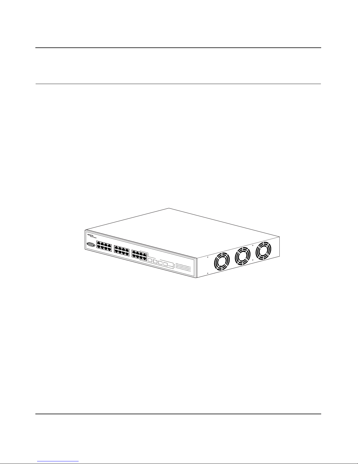
Figure 1 depicts the front and side views of the BayStack 380 Switch.
Figure 1 BayStack 380 Switch
Chapter 1 BayStack 380 Switch 25
10463FA
Using the BayStack 380 10/100/1000 Switch
Page 26
26 Chapter 1 BayStack 380 Switch
Front panel
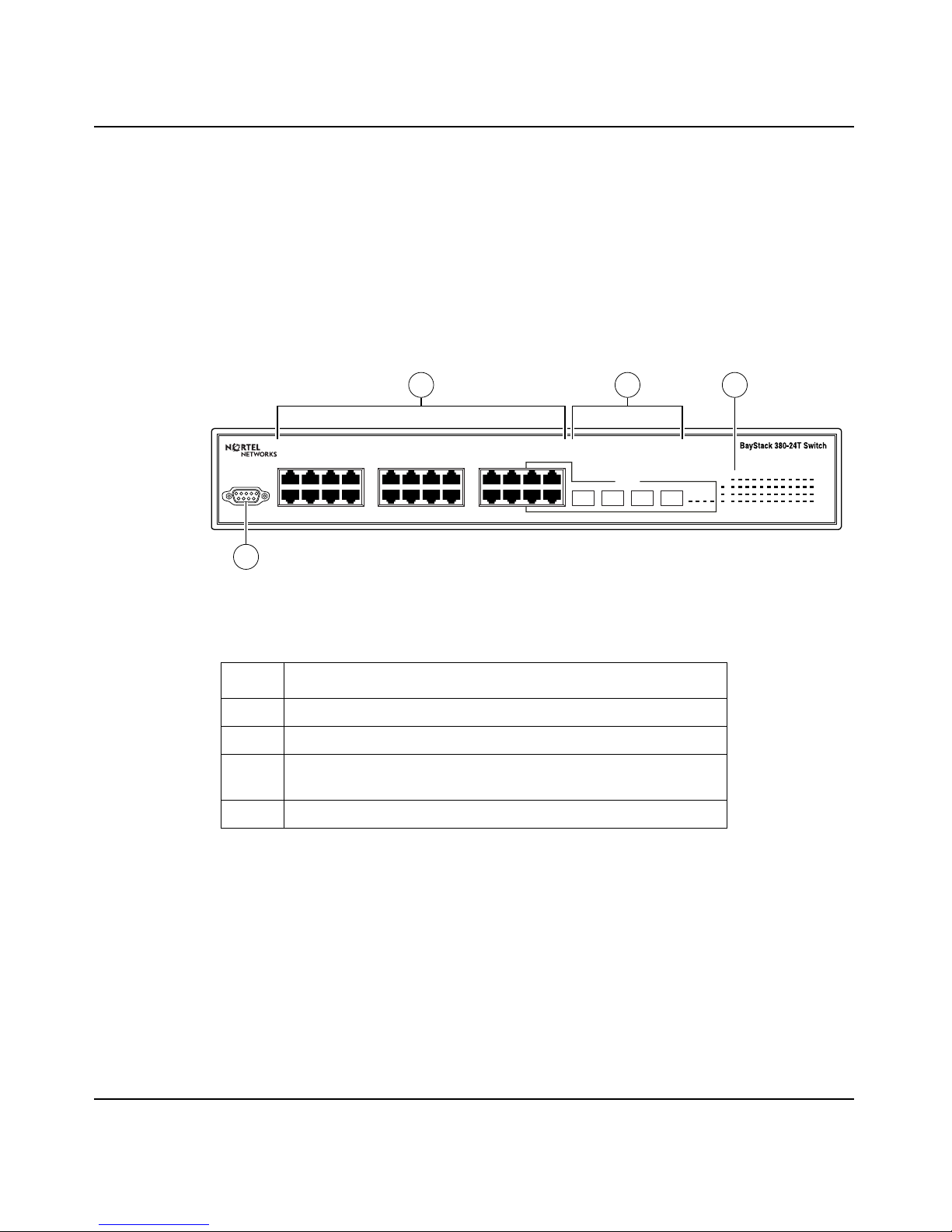
Figure 2 shows the configuration of the front panel on the BayStack 380 Switch.
Table 1 describes the components on the front panel.
For descriptions of the back panel BayStack 380 Switch components, see “Back
panel” on page 32.
Figure 2 BayStack 380 Switch
front panel
2 3
4
1234567
Console
1
8
9101112131415
17181920212223
16
BayStack 380-24T Switch
21 22 23 24
24
mini-GBIC
21 22
Table 1 Components on the BayStack 380 Switch front panel
Item Description
1 Console port
2 10/100/1000BASE-TX RJ-45 Port connectors
3 Small Form Fa ctor Pluggable (SFP) Gigabit Interface
Converter (mini-GBIC)
4 LED display panel
Console port
Pwr
Status
In use
RPSU
23
24
1 5 7 9 11 13 15 17 193
2 6 8 101214161820
21 23
10/100/1000
Activity
10/100/1000
Activity
22 244
10464EA
The Console port allows you to access the console interface (CI) screens and
customize your network using the supplied menus and screens (see Chapter 3,
“Using the console interface,” on page 93).
212859-A
Page 27

Chapter 1 BayStack 380 Switch 27
The Console port is a DB-9, RS-232-D male serial port connector. You can use
this connector to connect a management station or console/terminal to the
BayStack 380 Switch by using a straight-through DB-9 to DB-9 standard serial
port cable. You must use a VT100/ANSI-compatible terminal (for cursor control
and to enable cur so r and functi ons k e ys) to use t he cons ole po rt. Se e I nstalli ng the
BayStack 380 10/100/1000 Switch for more information.
Note: The console port is configured as a data communications
equipment (DCE) connector. Ensure that your RS-232 cable pinouts are
configured for DCE connections (see Appendix D, “Connectors and pin
assignments,” on page 201).
The Console port defau lt setti ngs are: 9600 baud wit h eight da ta bit s, one stop bi t,
and no parity as the com municati ons format, with flow cont rol set to ena bled.
Small Form Factor Pluggable (SFP) Gigabit Interface Converter
Small Form Factor Pluggable Gigabit Interface Converters are hot-swappable
input/output enhancement components designed for use with Nortel Networks
products to allow Gigabit Ethernet ports to link with Short Wavelength (SX),
Long Wave length (LX), and Coarse Wavelength Division Multiplexed (CWDM)
fiber optic networks.
Port connectors
The BayStack 380 Swit ch uses 10/ 100/1000B ASE-TX RJ-45 (8-pin modula r) port
connectors.
The 10/100/1000BASE-TX port connectors feature auto-MDI-X
(media-dependen t interf a ce-cross o v er). Thes e ports conn ect o v er st raight -through
cables to the network interface card (NIC) in a node or server, similar to a
conventional Ethernet repeater hub. However, with this feature and
auto-negotiation enabled, you can still use straight-through cables while
connecting to an Ethernet hub or switch.
For details on pin assignments and for directions on how to make your own
cross-over cables, see “Appendix D, “Connectors and pin assignments,” on page
201).
Using the BayStack 380 10/100/1000 Switch
Page 28
28 Chapter 1 BayStack 380 Switch
The BayStack 380 Switch uses autosensing ports designed to operate at 10 Mb/s
(megabits per second), 100 Mb/s, OR 1000 Mb/s (1 gigabit) depending on the
connecting dev ic e. These por ts supp ort the IEEE 802.3u, 802.3z for 1000SS, or
802.3ab for 1000TX autonegotiation standard, which means that when a port is
connected to another device that also supports the IEEE 802.3u, 802.3z for
1000SS, or 802.3ab for 1000TX s tandard, the two de vices ne gotia te the b est spee d
and duplex mode.
The BayStack 380 Switch features auto-polarity. With autonegotiation enabled,
auto-polarity automatically reverses the polarity of a pair of pins from positive to
negative or negative to positive. This corrects th e polarity o f the received data if
the port detect s tha t the pol arit y of t he dat a has been r e v er sed due to a wir ing er ror.
The 10/100/1000BASE-TX switch ports also support half- and full-duplex mode
operation at 10 Mb/s and 100 Mb/s (refer to Installing the BayStack 380 10/100/
1000 Switch).
The 10/100/1000BASE-TX RJ-45 ports can connect to 10 Mb/s or 100 Mb/s or
1000 Mb/s (1 gigabit) Ethernet segments or nodes.
Note: Use only Category 5 copper unshielded twisted pair (UTP) cable
connections when connecting 10/100/1000BASE-TX ports.
Note: IEEE 1000BASE- TX require s operati ng in ful l-duple x mode wi th
auto-negot i ati on enabled.
See Appendix D, “Connectors and pin assignments,” on page 201 for more
information about the RJ-45 port connectors.
212859-A
Page 29
Chapter 1 BayStack 380 Switch 29
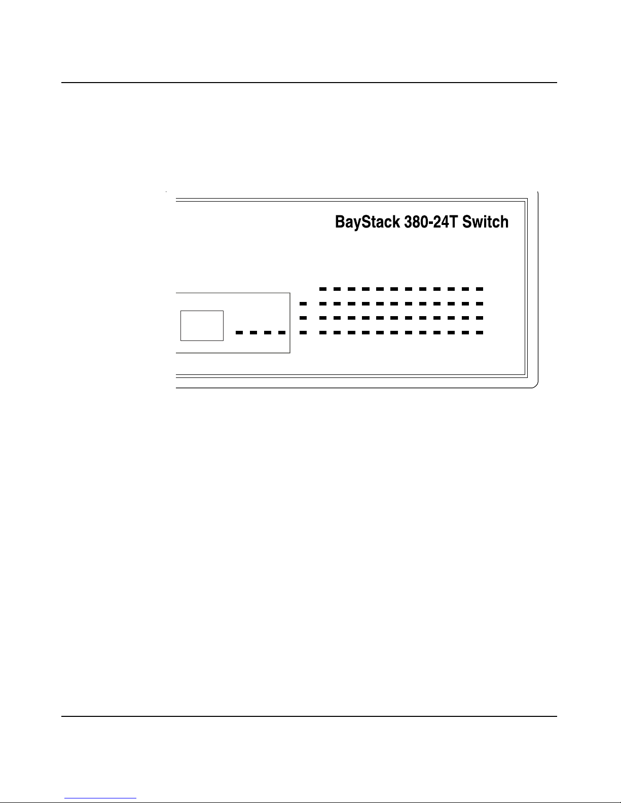
LED display panel
Figure 3 shows the BayStack 380 Switch LED display panel. See Table 2 for a
description of the LEDs.
Figure 3 BayStack 380 Switch LED display panel
24
21 22
In use
1 5 7 9 11 13 15 17 193
Pwr
Status
RPSU
23
24
2 6 8 101214161820
21 23
22 244
10/100/1000
Activity
10/100/1000
Activity
Using the BayStack 380 10/100/1000 Switch
Page 30

30 Chapter 1 BayStack 380 Switch
Table 2 BayStack 380 switch LED descriptions
Label Type Color State Meaning
Pwr Power status Green On DC power is available to the switch’s internal circuitry.
Off No AC power to switch or power supply failed.
Status System
status
RPSU RPSU status Green On The switch is connected to the RPSU and can receive
10/100/
1000
Speed/Link
Status
indicator
Green On Self-test passed successfully and switch is operational.
Blinking A nonfatal error occurred during the self-test. (This
includes nonworking fans.)
Off The switch failed the self-test.
power if needed.
Off The switch is not connected to the RPSU or RPSU is not
supplying power.
Alternating
Green/
Amber
(10) Blinking The corresponding 10 Mb/s port has been disabled by
Solid
Amber
(100) Blinking The corresponding port has been disabled by software.
On The corresponding port is set to operate at 10 Mb/s, and
the link is good.
software.
Off The link connection is bad, or there is no connection to
this port.
On The corresponding port is set to operate at 10 0 Mb/s , and
the link is good.
Off The link connection is bad, or there is no connection to
this port.
Solid
Green
(1000)
Activity Port activity Green Blinking Indicates network activity for the corresponding port. A
Note: The speed indicator LED for a port operating at 10 Mb/s is solid amber for 5
seconds, then switches to green for 1 seco nd. It altern ates in this way while the switch is
on.
212859-A
On The corresponding port is set to operate at 1000 Mb/s
and the link is good.
Blinking The corresponding 1000 Mb/s port has been disabled by
software.
Off The link connection is bad, or there is no connection to
this port.
high level of network activity can cause the LEDs to
appear to be on continuously.
Page 31

Chapter 1 BayStack 380 Switch 31
Multi-mode LEDs are used per port to display 10/100/1000BaseTX speed and
port status:
• 1000Mbps - solid green
• 100Mbps - solid amber
• 10Mbps - solid amber for 5 seconds, solid green for 1 second, repeat
• If the port is disabled, the port speed LED blinks at a rate of once per second:
• disabled 1000Mbps - blink green
• disabled 100Mbps - blink amber
• disabled 10Mbps - blink amber 5 times, blink green 1 time, repeat
• System ready LED
• Redundant powe r LED
Activity LED: to be driven directly by PHYs Mini-GBICs a nd the corre spondin g
copper ports are sharing the same activity LEDs
Mini-GBIC “In Use” LEDs: “In Use” is indicated by a green LED. If the “In Use”
LED is lit, then the 10/100/1000 LED for the corresponding RJ-45 port will be
off.
Using the BayStack 380 10/100/1000 Switch
Page 32

32 Chapter 1 BayStack 380 Switch
Back panel
The switch back panel is shown in Figure 4. Table 3 describes the components on
the back panel.
Figure 4 BayStack 380 Switch
2 1
100-240 V50-60Hz 2A
back panel
10474EA
back panel
Table 3 Components on the BayStack 380 Switch
Item Description
1 DC-DC module for the Redundant power supply unit
(RPSU)
2 AC power receptacle
Redundant power supply unit (RPSU) and uninterruptible
power supply (UPS)
The redundant power supply connector allows you to connect a backup power
supply unit to the BayStack 380 Switch. Nortel Networks provides an optional
redundant power supply unit (RPSU) for this purpose. The BayStack 10 Power
Supply Unit (Order number AA0005005) is a hot-swappable power supply unit
that provides uninterrupted operation to as many as four BayStack 380 Switches
in the event that any of the swit ch power supplies fail.
The BayStack 10 Power Supply Unit has a powerful, modular redundant and
uninterruptible power supply (UPS) functionality in a single chassis. It provides
scalable power redundancy and protection to your networking equipment. The
modules fit into the right-hand side of the rear of the chassis. The UPS and
associated battery pack module fit into the front of the chassis.
212859-A
Page 33

Chapter 1 BayStack 380 Switch 33
For further information, refer to Installation and Reference for the BayStack 10
Power Supply Unit (part number 208296-C). Contact your Nortel Networks sales
representa tive for more information.
DC-DC module
The 100 W at t DC-DC Con verter operates in conjunc tion with the Nort el Networks
BayStack 10 Power Supply Unit and 200 Watt AC/DC Power Supply Module.
The 100 Watt DC-DC Converter (Order number AA0005010) provides a
plug-and-play redundant power supply unit for the BayStack 380 Switch, as well
as other products available from Nortel Networks. Contact your Nortel Networks
sales representative for information about the Nortel Networks products that use
the 100 Watt DC-DC Converter.
AC power receptacle
The AC power receptacle accepts the AC power cord (supplied). For installation
outside of North Amer ica, mak e sure that you ha v e the prop er po wer cord f or your
region. Any cord used must have a CEE-22 standard V female connector on one
end and must meet the IEC 320-030 specif ic at ions. Table 4 lists specific at ions for
international power cords.
Table 4 International power cord specifications
Country/Plug description Specifications Typical plug
Continental Europe:
• CEE7 standard VII male plug
• Harmonized cord (HAR marking
on the outside of the cord jacket
to comply with the CENELEC
Harmonized Document HD-21)
U.S./Canada/Japan:
• NEMA5-15P male plug
• UL recognized (UL stamped
on cord jacket)
• CSA certified (CSA label
secured to the cord)
220 or 230 VAC
50 Hz
Single phase
100 or 120 VAC
50–60 Hz
Single phase
Using the BayStack 380 10/100/1000 Switch
228FA
227FA
Page 34

34 Chapter 1 BayStack 380 Switch
Table 4 International power cord specifications (continued)
Country/Plug description Specifications Typical plug
United Kingdom:
• BS1363 male plug with fuse
• Harmonized cord
Australia:
• AS3112-1981 Male plug
Caution: Please read immediately.
240 VAC
50 Hz
Single phase
229FA
240 VAC
50 Hz
Single phase
230FA
212859-A
Inspect this power cord and determine if it provides the proper plug and is
appropriately certified for use with your electrical system. Immediately discard this
cord if it is inappropriate for your country's electrical system and obtain the proper
cord as required by your national electrical codes or ordinances.
Refer to this product's technical documentation for detailed installation procedures to
be followed by qualified service personnel.
Vorsicht: Bitte sofort lesen.
Sehen Sie nach, ob dieses Netzkabel über den richtigen Stecker verfügt und für die
Verwendung in Ihrem Str omver sogungsnetz zertifiziert ist. Falls dieses Kabel nicht für
das Stromver sor g ungsnetz in Ihrem Land geeignet ist, darf es nicht verwendet werden.
Besorgen Sie sich ein Kabel, das die Vorschriften der Zulassungsbehörden in Ihrem
Land erfüllt.
Die technische Dokumentation dieses Produkts enthält ausführliche
Installationsanweisungen, die nur von qualifiziertem Kundendienstpersonal
ausgeführt werden dürfen.
Page 35

Chapter 1 BayStack 380 Switch 35
Attention: Lisez ceci immédiatement.
Examinez ce cor do n d'al imentati on pou r dét erminer s'il dispos e de l a f ic he appropriée
et s'il est bien agréé pour utilisation sur votre installation électrique.
Débarrassez-vous en immédiatement s'il ne convient pas à l'utilisation sur le secteur
électrique en usage dans votre pays et procurez-vous un cordon conforme à la
réglementation nationale en vigueur.
Reportez-vous à la documentation technique de ce produit pour obtenir des
instructions détaillées d'installation, destinées à un technicien qualifié.
Attenzione: Leggere attentamente.
Controllare questo cavo di alimentazione, verificarne il collegamento con la presa
appropriata nonché la certificazione per l'uso nell'impianto elettrico posseduto. Non
utilizzare assolutamente in caso tale cavo non sia adatto al sistema elettrico del paese
in cui viene utilizzato e richiederne un altro certificato dall'ente nazionale di fornitura
elettrica.
Per le procedure di installazione che devono essere seguite dal personale di servizio,
consultare questa documentazione tecnica del prodotto.
Advertencia: Sírvase leer inmediatamente.
Inspeccione este cable de alimentación eléctrica y determine si viene con el enchufe
apropiado y está debidamente certificado para el uso con su sistema eléctrico. Si no
cumple con los reglamentos del sistema eléctrico de su país, despójese de este cable de
alimentación inmediatamente y obtenga el cable requerido, según las ordenanzas y
códigos eléctricos nacionales.
Refiérase a la documentación técnica de este producto para recibir información
detallada sobre los procedimientos que el personal calificado de reparaciones deberá
seguir.
Caution:
Using the BayStack 380 10/100/1000 Switch
Page 36

36 Chapter 1 BayStack 380 Switch
Warning:
Removal of the power cord is the only way to turn off power to this
device. The power cord must always be connected in a location that can be
accessed quickly and safely in case of an emergency.
Vorsicht: Die Stromzufuhr zu diesem Gerät kann nur durch Ziehen des
Netzstromkabels unterbrochen werden. Die Netzsteckdose, an die das
Netzstromkabel angeschlossen ist, muß sich stets an einem Ort befinden, der
bei einem Notfall schnell und einfach zugänglich ist.
Avertissement: Le débranchement du cordon d'alimentation constitue le
seul moyen de mettre cet appareil hors tension. Le cordon d'alimentation doit
donc toujours êtr e branc hé dans u ne p rise a ccess ible po ur f acil iter la mise hors
tension en cas d'urgence.
Advertencia: La única forma de desconectar la alimentación de este
dispositivo es desenchufar el cable de alimentación. El cable de alimentación
siempre debe esta r conecta do en u na ubicaci ón que per mita acce der al c able de
forma rápida y segura en caso de emergencia.
Avvertenza: Estrarre il cavo di alimentazione è l'unico sistema per spegnere
il dispositivo. Il cavo di alimentazione deve essere sempre collegato in una
posizione che permetta l'accesso facile e sicuro in caso di emergenza.
Features
The BayStack 380 Switch provides wire-speed switching that allows
high-performance, low-cost connections to full-duplex and half-duplex
10/100/1000 Mb/s Ethernet local area networks (LANs). The BayStack 380
Switch provides the following features.
212859-A
Page 37

Chapter 1 BayStack 380 Switch 37
Virtual Local Area Networks (VLANs)
In a traditional shared-media network, traffic generated by a station is transmitted
to all other stations on the local segment. Therefore, for any given station on the
shared Ethernet, the local segment is the collision domain because traffic on the
segment has the potential to cause an Ethernet collision. The local segment is also
the broadcast domain because any broadcast is sent to all stations on the local
segment. Although Ethernet switches and bridges divide a network into smaller
collision domains, they do not affect the broadcast domain. In simple terms, a
virtual local area network provides a mechanism to fine-tune broadcast domains.
Your BayStack 380 Switch allows you to create port-based VLANs:
• IEEE 802.1Q port-based VLANs
A port-based VLAN is a VLAN in whic h the por ts are expli citly c onf igured t o
be in the VLAN. When you create a port-based VLAN, you assign a Port
VLAN Identifier (PVID) and specify which ports belong to the VLAN. The
PVID is us ed to coord inate VLAN s across multiple switches.
• Auto PVID
Security
The BayStack 380 Swi tch s ecurity fea tures pr o vide two levels of security for your
local area network (LAN):
• RADIUS-based security—limits administrative access to the switch through
• MAC address-based security—limits access to the switch based on allowed
Figure 5 shows a typical campus configuration using the BayStack 380 Switch
security features. This example assumes that the switch, the teachers’ offices and
classrooms, and the li brary are phy sical ly secured . The stude nt do rmitory may ( or
may not be) physically secure.
When Auto PVID is active, a port that is assigned to a numbered VLAN has
the same number for its PVID. For exa mple, if the VLAN is 2, the PVID is 2.
user authentication
source MAC addresses
Using the BayStack 380 10/100/1000 Switch
Page 38

38 Chapter 1 BayStack 380 Switch
Figure 5 BayStack 380 Switch security feature
Switch
RADIUS
server
To Network
Center
RADIUS-based
security
Student Dormitory
Legend
= Secure locked area
Teachers’ offices
and classrooms
Library
BS45077C
212859-A
Page 39

Chapter 1 BayStack 380 Switch 39
In this configuration example, the following security measures are implemented:
•The switch
— RADIUS-based security is used to limit administrative access to the
switch through user authentication (see “RADIUS-based network
security” on page 40).
— MAC address-based security is used to allow up to 448 authorized
stations (MAC addresses) access to one or more switch ports
(see “MAC address-based security” on page 40).
— The switch is located in a locked closet, accessible only by authorized
Technical Services personnel.
• Student dormitory
Dormitory rooms are typically occupied by two students and have been
prewired with two RJ-45 jacks. Only students who are authorized (as
specified by th e MAC address-based secur ity feature) can access the swit ch
on the secured ports.
• Teachers’ offices and classrooms
The PCs that are located in the teachers’ offices and in the classrooms are
assigned MAC address-based security that is specific for each classroom and
office location. The security feature logically locks each wall jack to the
specified station and prevents unauthorized access to the switch should
someone attempt to connect a personal laptop PC into the wall jack. The
printer is assigned as a single station and is allowed full bandwidth on that
switch port.
It is assumed that all PCs are password protected and that the classrooms and
offices are physically secured.
• Library
The wall jacks in the library are set up so that the PCs can be connect ed to any
wall jack in the room. T his arrangement allows the PCs to be moved
anywhere in the room. The exception is the printer, which is assigned as a
single station with full bandwidth to that port.
It is assumed that all PCs are p ass word protec te d and th at acc ess t o th e librar y
is physically secured.
Using the BayStack 380 10/100/1000 Switch
Page 40

40 Chapter 1 BayStack 380 Switch
RADIUS-based network security
The RADIUS-based security feature allows you to set up network access control,
using the RADIUS (Remote Authentication Dial-In User Services) security
protocol. The RADIUS-based security feature uses the RADIUS protocol to
authenticate local console and Telnet logins.
You will need to set up specific user accounts (user names and passwords, and
Service-Type attributes) on your RADIUS server before the authentication
process can be initiated. To provide each user with appropriate levels of access to
the switch, set the following username attributes on your RADIUS server:
• Read-write access—Set the Service-Type field value to Administrative.
• Read-only access—Set the Service-Type field value to NAS-Prompt.
For detailed instructions to set up your RADIUS server, refer to your RADIUS
server documentation.
For instructions to use the console interface (CI) to set up the RADIUS-based
security feature, see Chapter 3, “Using the console interface,” on page 93.
MAC address-based security
The MAC address-based security feature allows you to set up network access
control, based on source MAC addresses of authorized stations.
You can:
• Create a list of up to 448 MAC addresses and specify which addresses are
authorized to connect to your switch configuration. The 448 MAC addresses
can be configured within a single standalone switch.
• Specify which of your switch ports each MAC address is allowed to access.
The options for allowed port access include: NONE, ALL, and a single port.
The MAC address-based security feature is based on Nortel Networks BaySecure
LAN Access for Ethernet, a real-time security system that safeguards Ethe rnet
networks from unauthorized surveillance and intrusion.
212859-A
Page 41

For instructions to use the console interface (CI) to set up the RADIUS-based
security feature, see Chapter 3, “Using the console interface,” on page 93.
Flash memory storage
Switch software im age storage
The BaySt ack 380 Switch uses flash memory to store the switch software image.
The flash memory allows you to update the softwa re image with a newer version
without changing the switch hardware (see “Software Download screen” on
page 164). An in-band connection between the switch and the TFTP load host is
required to download the s oftware image.
Configuration parameters storage
All configuration parameters are stored in flash memory. These parameters are
updated every 60 seconds (if a change occurs) or whenever a reset command is
executed.
Chapter 1 BayStack 380 Switch 41
Warning: Do not power off the switch within 10 seconds of changing
any configuration parameters. Powering down the switch within 10
seconds of changing configuration parameters can cause the changed
configuration parameters to be lost.
MultiLink Trunking
The MultiLink Trunking feature allows you to group multiple ports, two to four
together, when forming a link to another switch or server, thus increasing
aggregate throughput of the interconnection between two devices, up to 8 Gb/s in
full-duplex mode. The BayStack 380 Switch can be configured with up to six
MultiLink Trunks.
For more information about the MultiLink Trunking feature, see “MultiLink
Trunk Configuration Menu screen” on page 136.
Using the BayStack 380 10/100/1000 Switch
Page 42

42 Chapter 1 BayStack 380 Switch
Po rt mirroring (conversation steering)
The port mirroring feature (sometimes referred to as conversation steering) allows
you to designate a single switch port as a traffic monitor for a specified port. You
can specif y port-based monitoring for ingress and egress at a specific port. You
can also attach a probe device (such as a Nortel Networks StackProbe, or
equivalent) to the designated monitor port.
For more information about the port mirroring feature, see “Port Mirroring
Configuration screen” on page 142.
Autosensing, autonegotiation, auto-MDI/X, and autopolarity
The BayStack 380 switches are autosensing and autonegotiating devices:
• The term autosense refers to a port’s ability to sense the speed of an attached
device.
• The term autonegotiation refers to a standardized protocol (IEEE 802.3u or
802.3z or 802.3ab) that exists between two IEEE -capable devices.
Autonegotiation allows the switch to select the best of both speed and duplex
modes.
• The term autopolarity refers to automatic detection of transmit and receive
twisted pairs.
Autosensing is used when the attac hed device is not capable of autone gotiation or
is using a form of autonegotiation that is not compatible with the IEEE 802.3z
autonegotiation standard. In this case, because it is not possible to sense the
duplex mode of the attached device, the BayStack 380 Switch reverts to
half-duplex mode.
When autonegotiation-capable devices are attached to the BayStack 380 Switch,
the ports negotiate down from 1000 Mb/s speed and full-duplex mode until the
attached device acknowledges a supported speed and duplex mode.
Auto-MDI-X detects receive and transmit twisted pairs automatically. When
auto-MDI-X is active, any straight or crossover category 5 cable can be used to
provide connection to a port. If autonegotiation is disabled, then auto-polarity is
not active.
212859-A
Page 43

Chapter 1 BayStack 380 Switch 43
The BayStack 380 Switch features auto-polarity. With autonegotiation enabled,
auto-polarity automatically reverses the polarity of a pair of pins from positive to
negative or negative to positive. This corrects th e polarity o f the received data if
the port detect s tha t the pol arit y of t he dat a has been r e v er sed due to a wir ing er ror.
For more information about autosensing and autonegotiation modes, see
Chapter 4, “Troubleshooting,” on page 171.
RFCs
For more information about networking concepts, protocols, and topologies,
consult the following RFCs:
• RFC 1213 (MIB-II)
• RFC 1493 (Bridge MIB)
• RFC 1573 (Interface MIB)
• RFC 1643 (Ethernet MIB)
• RFC 1757 (RMON)
• RFC 1271 (RMON)
• RFC 1157 (SNMP)
Standards
The following IEEE Standards also contain information germane to the BayStack
380 Switch:
• IEEE 802.3 10BASE-T (ISO/IEC 8802-3, Clause 14)
• IEEE 802.3u 100BASE-TX (ISO/IEC 8802-3, Clause 25)
• IEEE 802.3ab 1000BASE-T
• IEEE 802.3z (gigabit ethernet)
• IEEE 802.1Q (VLAN Tagging)
• IEEE 802.3x (Flow Control with 802.1D compliant device)
• IEEE 802.1D (Spanning tree protocol)
• IEEE 802.1p (Prioritization)
Using the BayStack 380 10/100/1000 Switch
Page 44

44 Chapter 1 BayStack 380 Switch
SNMP MIB support
The BayStack 380 Switch supp ort s an SNMP agent with indu st ry st an dar d MI Bs,
as well as private MIB extensions, which ensures compatibility with existing
network management tools. The switch supports the MIB-II (RFC 1213), Bridge
MIB (RFC 1493), and the RMON MIB (RFC 1757), which provide access to
detailed management statistics. With SNMP management, you can configure
SNMP traps (on indi vid ual ports) to gener ate aut omat icall y for cond itio ns suc h as
an unauthorized access attempt or changes in a port’s operating status. Table 5
lists supported SNMP MIBs.
Table 5 SNMP MIB support
Application Standard MIBs Proprietary MIBs
S5 Chassis MIB s5cha127.mib
S5 Agent MIB s5age140.mib
RMON rfc1757.mib
MLT rcMLT
SNMPv3 MIBs RFCs 2571, 2572,
2573, 2574, 2575,
2576
MIB2 rfc1213.mib
IF-MIB rfc2233.mib
Etherlike MIB rfc1643.mib
Interface Extension MIB s5ifx100.mib
Switch Bay Secure s5sbs102.m ib
System Log MIB bnlog.mib
S5 Autotopology MIB s5emt104.mib
VLAN rcVlan
Entity MIB RFC 2037
Spanning Tree RFC1493 Bridge
MIB
212859-A
Page 45

Chapter 1 BayStack 380 Switch 45
SNMP trap support
The BayStack 380 Switch supports an SNMP agent with industry standard
SNMPv1 traps, as well as private SNMPv1 trap extensions (Table 6).
Table 6 Support SNMP traps
Trap name Configurable Sent when
RFC 1215 (industry standard):
linkUp Per port A port’s link state changes to up.
linkDown Per port A port’s link state changes to down.
authenticationFailure System wide There is an SNMP authentication failure.
coldStart Always on The system is powered on.
warmStart Always on The system restarts due to a management
reset.
s5CtrMIB (Nortel proprietary traps):
s5CtrUnitUp Always on A unit is added to a configuration.
s5CtrUnitDown Always on A unit is removed from a configuration.
s5CtrHotSwap Always on A unit is hot-swapped in a configuration.
s5CtrProblem Always on An assigned unit fails.
s5EtrSbsMacAccessViolation Always on A MAC address violation is detected.
BootP automatic IP configuration/MAC address
The BayStack 380 Switch has a unique 48-bit hardware address, or MA C addr ess,
that is printed on a label on the back panel. You use this MAC address when you
configure the network BootP server to recognize the BayStack 380 Switch BootP
requests. A properly configured BootP server enables the switch to automatically
learn its assigned I P address, su bnet mask , IP address of the defa ult route r (def ault
gateway), and software ima ge file name.
Using the BayStack 380 10/100/1000 Switch
Page 46

46 Chapter 1 BayStack 380 Switch
The BootP Request Mode field in the IP Configuration screen allows you to
choose which method the switch uses to broadcast BootP requests:
• BootP When Needed
• BootP Always
• BootP Disabled
• BootP or Last Address
Note: Whenever the switch is broadcasting BootP requests, the BootP
process will eventually time out if a reply is not received. When the
process times out, the BootP request mode automatically changes to
BootP Disabled mode. To restart the BootP process, change the BootP
request mode to any of the three following modes:
• BootP When Needed
• BootP Always
•
BootP or Last Address
.
For more information and an example of a BootP configuration file, see
Appendix F, “Sample BootP configuration file,” on page 211.
Configuration and switch management
The BayStack 380 Switch is shipped directly from the factory ready to operate in
any 10BASE-T, 100BASE-TX, or 1000BASE-TX standard network.
You must assign an IP address to the switch, depending on the mode of operation.
You can set both addresses by using the console port or BootP, which resides on
the switch. You can manage the switch using:
• Console interface
The console interface allows you to configure and manage the switch locally
or remotely. Access the CI menus and screens locally through a console
terminal attached to your BayStack 380 Switch, remotely through a dial-up
modem connection, or in-band through a Telnet session.
For information about the console interface, see Chapter 3, “Using the
console interface,” on page 93.
212859-A
Page 47

Chapter 1 BayStack 380 Switch 47
• Web-based management
You can manage the network from the World Wide Web. Acce ss the
Web-based graphical user inte rface (GUI) through the Embedded Web Server
(EWS), the HTML-based browser located on your network. The GUI allows
you to confi gur e, monitor , and maintain your net work through Web browsers .
You can also download software using the Web.
For information about Web-based management, refer to Using Web-Based
Management for the BayStack 380 10/100/1000 Switch.
• Java-based Device Manage r
Device Manager is a Java -based set of graphical network management
applications used to configure and manage a BayStack 380 Switch. See
Reference for the BayStack 380 10/100/1000 Switch Management Software
for more information.
• Any generic SNMP-based network management software.
You can use any generic SNMP-based network management software to
configure and manage a BayStack 380 Switch.
• Nortel Networks Optivity* network management software
Optivity network management software consists of views, most of which are
maps that illustrate the interconnections between the segments, rings, and
nodes of your netw or k. The views allow you to analyze networ k per fo rmance
and fault conditions on the individual segments and specific areas in your
network. They can also alert you when a problem has occurred in a specific
location. For further information about Optivity, contact your Nortel
Networks sales representative.
Using the BayStack 380 10/100/1000 Switch
Page 48

48 Chapter 1 BayStack 380 Switch
212859-A
Page 49

Chapter 2
Network configuration
Use BayStack 380 switches to connect workstations, personal computers (PCs),
and servers to each other by connecting these devices directly to the switch,
through a shared media hub connected to the switch or by creating a virtual LAN
(VLAN) through the switch.
This chapter describes the following topics:
• “Network configuration examples,” next
• “IEEE 802.1Q VLAN workgroups” on page 55
• “IEEE 802.1p Prioritizing” on page 71
• “MultiLink Trunks” on page 74
• “Port mirroring” on page 91
49
Network configuration examples
This section provides four network configuration examples using BayStack 380
switches. In these examples, the packet classification feature can be used to
prioritize the traffic of the network to ensure uninterrupted traffic of critical
applications. The examples are:
• High-bandwidth Desktop switch configuration (next)
• High-bandwidth server configuration
• OEL2 Aggregation
• Layer 2 Aggregator
Using the BayStack 380 10/100/1000 Switch
Page 50

50 Chapter 2 Network configur ati on
High-bandwidth Desktop switch configuration
Figure 6 shows a BayStack 380 Switch used as a desktop switch, where desktop
workstations are connected directly to BayStack 380 switch ports. A Passport
8600 provides high-capacity and low latency connections to the rest of the
network. Users can transfer files to and from the network with much greater
speed. Configuring a high bandwidth desktop configuration requires only three
major step s:
1 Configure the multi-link transfer (MLT) ports that link to the Passport 8600
2 Configure the MLT ports on the Pas sport 860 0 that a ttach to t he BayStack 380
switch.
3 Attach one or more high-speed workstations to the BayStack 380 switch.
Figure 6 BayStack 380 Switch used as a desktop switch
PP 8600
212859-A
MLT
BayStack
380
10565EA
Page 51

Chapter 2 Network configuration 51
High-bandwidth server configuration
Figure 7 shows an example of a BayStack 380 Switch used to service a group of
servers, where the ser ver s are connected directl y to BayS tac k 380 s wi tc h por ts . A
Passport 8600 provides high-capacity and low latency connections to the rest of
the network. The BayStack 380 provides up to four gigabit links for each server,
and can balance the high speed server connect ions with multi- gigabit links back to
the network. The BayStack 380 also provides configuration of multiple 10/100/
1000 Mbps link. This allows for the evolution of connections from a single 10
Mbps connection to a multi-gigabit connection without requiring another switch.
Configuring a high-bandwidth server configuration requires only four major
steps:
1 Configure the network servers .
2 Configure the mu lti-link tra nsfer (MLT) ports on the BaySta ck 380 that link to
the network servers .
3 Configure the MLT ports that link to the Passport 8600.
4 Configure the MLT ports on the Passport 8600 that attach to the BayStack
380.
Using the BayStack 380 10/100/1000 Switch
Page 52

52 Chapter 2 Network configur ati on
Figure 7 BayStack 380 used in a high-bandwidth server configuration
BayStack
380
PP 8600
MLT
OEL2 Aggregation
212859-A
10566EA
Figure 8 shows an example of the BayStack 380 used to aggregate the uplink
connection from OPTera Metro 1200 Ethernet Service modules (OM 1200 ESM)
at one site to a Passport 8600 at another site. Inexpensive copper connections can
be used to conne ct t he OM 120 0 OSM u nits to t he BaySt ack 380 at one s ite, while
small form fact or plugg able gig abit in terf ace conne ctors (SFP GBICs) c onnect the
BayStack 380 to the Passport 8600 at the other site.
Configuring the OEL2 aggregation requires four major steps:
1 Configure the OM 1200 ESM units
2 Configure the multi-link transfer (MLT) ports that link the OM 1200 ESM
units to the BayStack 380.
Page 53

Chapter 2 Network configuration 53
3 Configure the MLT ports on the BayStack 380 that link to the Passport 8600.
4 Configure the MLT ports on the Passport 8600 that link to the BayStack 380.
Figure 8 BayStack 380 used in an OEL2 Aggregation
PP 8600
MLT
BayStack
380
OM 1200 ESM OM 1200 ESM
Layer 2 Aggregator
Figure 9 shows an example of the BayStack 380 used to aggregate the uplink
connection from several Business Policy Switch 2000 (BPS 2000) switches to a
Passport 8600.
Configuring the BayStack 380 as a layer 2 aggregator requires three major steps:
1 Attach the BPS 2000 switches to tagged VLAN ports on the BayStack 380
2 Configure the multi-link transfer (MLT) ports on the BayStack that connect to
the Passport 8600.
10567EA
Using the BayStack 380 10/100/1000 Switch
Page 54

54 Chapter 2 Network configur ati on
3 Configure the MLT ports on the Passport 8600 that connect to the BayStack
380.
Figure 9 Layer 2 Aggregator
BayStack
380
PP 8600
MLT
212859-A
BPS 2000
Stack
BPS 2000
Stack
BPS 2000
Stack
10568EA
Page 55

IEEE 802.1Q VLAN workgroups
BayStack 380 switches support up to 64 port-based VLANs with IEEE 802.1Q
tagging available per p ort . Por ts are grou ped i nt o broadcast domains by assi gni ng
them to the same VLAN. Frames received in one VLAN can only be forwarded
within that VLAN, and multi ca st fr ames and unknown unicast f rames are flooded
only to ports in the same VLAN.
Setting up virtual LANs (VLANs) is a way to segment networks to increase
network capacity and performance without changing the physical network
topology (Figure 10). With network segmentation, each switch port connects to a
segment that is a si ngle broadcast domain . When a switch port is con fi gur ed t o be
a member of a VLAN, it is added to a group of ports (workgroup) that belong to
one broadcast domain.
The BayStack 380 Switch allows you to assi gn ports to VLANs u sing the con sole,
Telnet, Web-based management, or an appropriate SNMP-based application. You
can assign different ports (and therefore the devices attached to these ports) to
different broadcast domains. This feature allows network flexibility because you
can reassign VLANs to accommodate network moves, additions, and changes,
eliminating the need to change physical cabling.
Chapter 2 Network configuration 55
Figure 10 Port-bas ed VLAN example
VLAN 1 VLAN 2
BayStack
380
Using the BayStack 380 10/100/1000 Switch
10004EB
Page 56

56 Chapter 2 Network configur ati on
IEEE 802.1Q tagging
BayStack 380 switches operate in accordance with the IEEE 802.1Q tagging
rules. Important terms used with the 802.1Q tagging feature are:
• VLAN identifier (VID)—the 12 -bit portion of the VLAN tag in th e frame
header that identifies an explic it VLAN. Wh en other types of VLAN s are
enabled, this default value can be overridden by the values enabled in the
Web-based management interface. Refer to Using Web-Based Management
for the BayStack 380 10/100/1000 Switch.
• Port VLAN identif i er (PVID)—a classification mechanism tha t associates a
port with a specific VLAN. For example, a port with a PVID of 3 (PVID =3)
assigns all untagged frames received on this port to VLAN 3.
• Tagged frame— the 32-bit field (VLAN tag) in the frame header that
identifies the frame as belonging to a specific VLAN. Untagged frames are
marked (tagged) with this classification as they leave the switch through a
port that is configured as a tagged port.
• Untagged frame— a frame th at does not carr y any VLAN tagging infor mation
in the frame header.
• VLAN port members— a set of ports that form a broadcast domain for a
specific VLAN. A port can be a member of one or more VLANs.
• Untagged member—a port that has been configured as an untagged member
of a specific VLAN. When an untagged frame exits the switch through an
untagged member port, the frame header remains unchanged. When a tagged
frame exits the switch through an untagged member port, the tag is stripped
and the tagged frame is changed to an untagged frame.
• Tagged member—a port that has been configured as a member of a specific
VLAN. When an untagged frame exits the switch through a tagged member
port, the frame header is modified to include the 32-bit tag associated with the
PVID. When a tagged frame exits the switch through a tagged member port,
the frame header rema ins unchanged (origi nal VID remains).
• User priority—a three-bit field in the header of a tagged frame. The field is
interpreted as a b inary number, therefore has a value of 0 - 7. This f ield allows
the tagged frame to carry the user-priority across bridged LANs where the
individual LAN segments may be unable to signal priority information.
• Port priority—the priority level assigned to untagged frames received on a
port. This value becomes the user priority for the frame. Tagged packets get
their user priority from the value contained in the 802.1Q frame header.
212859-A
Page 57

Chapter 2 Network configuration 57
• Unregistered pac ket—a tagge d frame that cont ains a VID whe re th e rec eiving
port is not a member of that VLAN.
The default configuration settings for BayStack 380 switches have all ports set as
untagged members of VLAN 1 with all ports configured as PVID = 1. Every
VLAN is assigned a unique VLAN identifier (VID) that distinguishes it from all
other VLANs. In the default configuration example shown in Figure 11, all
incoming packets are assigned to VLAN 1 by the default port VLAN identifier
(PVID =1). Untagged packets enter and leave the switch unchanged.
Figure 1 1 Default VLAN settings
802.1Q Switch
VLAN 1
Port 1
PVID = 1
DA
SA
Incoming
untagged
packet
Key
By default:
Data
CRC
All ports are assigned PVID = 1
All ports are untagged members of VLAN 1
Port 2 Port 3 Port 4 Port 5
CRC
Outgoing
untagged packet
(unchanged)
Data
SA
DA
Port 6 Port 7 Port 8
BS45010A
When you configure VLANs, you configure the switch ports as tagged or
untagged members of specific VLAN s (see Figure 12 through Figure 20).
Using the BayStack 380 10/100/1000 Switch
Page 58

58 Chapter 2 Network configur ati on
In Figure 12, untagged incoming packets are assigned directly to VLAN 2
(PVID = 2). Port 5 is configured as a tagged member of VLAN 2, and port 7
is configured as an untagged me mber of VLA N 2 .
Figure 12 Port-based VLAN assignment
PVID = 2
Untagged packet
Before
Port 1
DASADataCRC
Port 4
Port 6
Port 2 Port 3
802.1Q Switch
Port 7 Port 8
Untagged member
of VLAN 2
As shown in Figure 13, the untagged packet is marked (tagged) as it leaves the
switch through port 5, which is configured as a tagged member of VLAN 2. The
untagged packet remains unchanged as it leaves the switch through port 7, which
is configured as an untagged member of VLAN 2.
Figure 13 802.1Q tagging (after port-based VLAN assignment)
PVID = 2
Port 1
Port 4
Port 2 Port 3
802.1Q Switch
Tagged member
of VLAN 2
Port 5
Tagged member
of VLAN 2
Port 5
BS45011A
DASADataCRC* Tag
Untagged member
212859-A
Port 6 Port 7 Port 8
of VLAN 2
Outgoing
untagged packet
(unchanged)
CRC
Data
SA
DA
(*Recalculated)
Key
Priority
CFI
VID
8100 CFI
16 bits 3 bits 1 bits 12 bits
After
- User_priority
- Canonical format indicator
- VLAN identifier
VID = 2Priority
BS45012A
Page 59

In Figure 14, tagged incoming packets are assigned directly to VLAN 2 because
of the tag assignment in the packet. Port 5 is configured as a tagged member of
VLAN 2, and port 7 is configured as an untagged member of VLAN 2.
Figure 14 802.1Q tag assignment
Chapter 2 Network configuration 59
Tagged packet
Before
PVID = 2
DASATagDataCRC
Port 1
Port 4
Port 6
Port 2 Port 3
802.1Q Switch
Port 7 Port 8
As shown in Figure 15, the tagged packet remains unchanged as it leaves the
switch through port 5, which is configured as a tagged member of VLAN 2.
However, the tagged packet is stripped (untagged) as it leaves the switch through
port 7, which is configured as an untagged member of VLAN 2.
Figure 15 802.1Q tagging (after 802.1Q tag assignment)
PVID = 2
Port 1
Port 4
Port 2 Port 3
802.1Q Switch
Port 5
Tagged member
of VLAN 2
Tagged member
of VLAN 2
Port 5
Untagged member
of VLAN 2
BS45013A
DASADataCRC Tag
Port 6 Port 7 Port 8
Untagged member
of VLAN 2
CRC*
Data
SA
DA
(*Recalculated)
Outgoing
untagged packet
changed
(tag removed)
VID = 2Priority
BS45014A
Key
Priority
CFI
VID
8100 CFI
16 bits 3 bits 1 bit 12 bits
After
- User_priority
- Canonical format indicator
- VLAN identifier
Using the BayStack 380 10/100/1000 Switch
Page 60

60 Chapter 2 Network configur ati on
VLANs spanning multiple switches
You can use VLANs to segment a network within a switch. When you connect
multiple switches, it is possible to connect users of one VLAN with users of that
same VLAN in another switch. However, the configuration guidelines depend on
whether both switches support 802.1Q tagging.
With 802.1Q tagging enabled on a port for a VLAN, all frames leaving the port
for that VLAN are marked as belonging to that specific VLAN. You can assign
specific switch ports as members of one or more VLANs that span multiple
switches, without interfering with the Spanning Tree Pro tocol.
VLANs spanning multiple 802.1Q tagged switches
Figure 16 shows VLANs spanning two BayStack 380 switches. The 802.1Q
tagging is enable d on S1, por t 2 and on S2, po rt 1 fo r VLAN 1 and VLAN 2. Bot h
ports are tagged members of VLAN 1 and VLAN 2.
Figure 16 VLANs spanning multiple 802.1Q tagged switches
VLAN 1
S1
Both ports are tagged
members of VLAN 1
and VLAN 2
S2
VLAN 2
BayStack
380
BayStack
380
10480EA
212859-A
Page 61

Chapter 2 Network configuration 61
Because there is only one link between the two switches, the Spanning Tree
Protocol (STP) trea ts this configu rati on as any other s wit ch- to- swi tc h c onnection.
For this configuration to work properly, both switches must support the 802.1Q
tagging protocol.
VLANS spanning multiple untagged switches
Figure 17 shows VLANs spanning multiple untagged switches. In this
configuration, Switch S2 does not support 802.1Q tagging and you must use a
single switch port on each switch for each VLAN.
For this configuration to work properly, you must set spanning tree participation
to Disabled (the STP is not supported across multiple LANs).
Figure 17 VLANs spanning multiple untagged switches
VLAN 1
S1
Untagged ports
S2
VLAN 2
BayStack 380
Non-802.1Q
tagging switch
10481EA
When the STP is enabled on these switches, only one link between each pair of
switches will be for w ar din g t raffic. Bec aus e each port belongs t o only one VLAN
at a time, connectivit y on the othe r VLAN is lost. Exe rcise care when conf igur ing
the switches to ensure that the VLAN configuration does not conflict with
spanning tree configuration.
Using the BayStack 380 10/100/1000 Switch
Page 62

62 Chapter 2 Network configur ati on
To connect multiple VLANs across switches with redundant links, you must
disable the STP on all participating switch ports. Figure 18 shows possible
consequences of enabling the STP when using VLANs between untagged
(non-802.1Q tagged) switches.
Figure 18 Possible problems with VLANs and Spanning Tree Protocol
Station A
BayStack 380
S1
No
Communications
Station B
VLAN 2
Blocking
VLAN 1
BayStack 380
VLAN 1
Forwarding
VLAN 2
S2
10482EB
As shown in Figure 18, with STP enabled, only one connection between Switch
S1 and Switch S2 is forwarding at any time. Communications failure occurs
between VLAN 2 of S1 and VLAN 2 of S2, blocking communications between
Stations A and B.
The STP selects the link connecting VLAN 1 on Switches S1 and S2 as the
forwarding link based on port speed, duplex-mode, and port priority. Because the
other link connecting VLAN 2 is in Blocking mode, stations on VLAN 2 in
Switch S1 cannot communicate with stations in VLAN 2 on Switch S2. With
multiple links only on e link will b e forwardi ng.
212859-A
Page 63

Shared servers
BayStack 380 switches allow ports to exist in multiple VLANs for shared
resources, such as servers, printers, and switch-to-switch connections. It is also
possible to have resources exist in multiple VLANs on one switch as shown in
Figure 19.
In this example, clients on different broadcast domains share resources. The
broadcasts from ports configured in VLAN 3 can be seen by all VLAN port
members of VLAN 3.
Figure 19 Multiple VLANs sharing resources
S1
Chapter 2 Network configuration 63
BayStack 380
V2 V2 V1
Key
VLAN 1 (PVID=1)
VLAN 2 (PVID=2)
VLAN 3 (PVID=3)
V3
V1V2
10483EA
Using the BayStack 380 10/100/1000 Switch
Page 64

64 Chapter 2 Network configur ati on
In the above configuration, all of the switch ports are set to participate as VLAN
port members. This arrangement allows the switch to establish the appropriate
broadcast domains within the switch (Figure 20).
Figure 20 VLAN broadcast domains within the switch
S1
VLAN 3
VLAN 2 VLAN 1
Port 2
PVID = 2 PVID = 3
V2 V2 V2 V1 V2
Key
VLAN 1 (PVID = 1)
VLAN 2 (PVID = 2)
VLAN 3 (PVID = 3)
Port 4 Port 10 Port 8
V3
Port 11Port 6
PVID = 1
BS45019A
For example, to create a broadcast domain for each VLAN shown in Figure 20,
configure each VLAN with a po rt membershi p, and each por t with the a ppropriat e
PVID/VLAN association:
• Ports 8, 6, and 11 are untagged members of VLAN 1.
• The PVID/VLAN association for ports 6 and 11 is: PVID = 1.
• Ports 2, 4, 10, and 8 are untagged members of VLAN 2.
• The PVID/VLAN association for ports 2, 4, and 10 is: PVID = 2.
• Ports 2, 4, 10, 8, 6, and 11 are untagged members of VLAN 3.
• The PVID/VLAN association for port 8 is: PVID = 3.
The following steps show how to use the VLAN configuration screens to
configure the VLAN 3 broadcast domain shown in Figure 20.
212859-A
Page 65

To configure the VLAN port membership for VLAN 1:
1 Select Switch Configuration from the BayStack 380 Switch Main Menu
(or press w).
2 From the Switch Configuration Menu, select VLAN Configuration
(or press v).
3 From the VLAN Configuration Menu select VLAN Configuration
(or press v).
The default VLAN Configuration screen opens (Figure 21).
Figure 21 Default VLAN Configuration screen example
Chapter 2 Network configuration 65
The VLAN Configuration screen settings shown in Figure 21 are default settings
with all switch ports classified as untagged members of VLAN 1.
Figure 22 shows the VLAN Configuration screen after it is configured to support
the VLAN 3 broadcast domain shown in Figure 20 on page 64 (VLAN Name is
optional).
Using the BayStack 380 10/100/1000 Switch
Page 66

66 Chapter 2 Network configur ati on
Ports 2, 4, 6, 8, 10, and 11 are now untagged members of VLAN 3 as shown in
Figure 20 on page 64.
Figure 22 VLAN Configuration screen example
212859-A
To configure the PVID (port VLAN identifier) for port 8:
1 From the VLA N Configur ation scree n, press [Ctrl]-R to return to the VLA N
Configuration Menu.
2 From the VLAN Configuration Menu, select VLAN Port Configuration
(or press c).
The default VLAN Port Configuration screen opens (Figure 23).
The VLAN Port Configuratio n scr ee n set ti ngs shown in Figure 23 are default
settings.
Page 67

Figure 23 Default VLAN Port Configuration screen example
Chapter 2 Network configuration 67
Figure 24 shows the VLAN Port Configuration screen after it is configured to
support the PVID assignment for port 8, as shown in Figure 20 on page 64 (Port
Name is optional).
The PVID/VLAN association for VLAN 3 is now PVID = 3.
Using the BayStack 380 10/100/1000 Switch
Page 68

68 Chapter 2 Network configur ati on
Figure 24 VLAN Port Configuration screen example
VLAN workgroup summary
This section summarizes the VLAN workgroup examples discussed in the
previous sections of this chapter.
As shown in Figure 25, Switch S1 (BayStack 380 Switch) is configured with
multiple VLANs:
• Ports 1, 6, 11, and 12 are in VLAN 1.
• Ports 2, 3, 4, 7, and 10 are in VLAN 2.
• Port 8 is in VLAN 3.
Because S4 does not support 802.1Q tagging, a single switch port on each switch
must be used for each VLAN (see “VLANS spanning multiple untagged
switches” on page 61).
The connection to S2 requires only one link between the switches because S1 and
S2 are both BayStack 380 switches that support 802.1Q tagging (see “VLANs
spanning multiple 802.1 Q tag ged swit ch es” on page 60).
212859-A
Page 69

Figure 25 VLAN configuration spanning multiple switches
Chapter 2 Network configuration 69
Non-802.1Q
tagging switch
S4
Untagged ports
(STP disabled)
S1
V2 V2 V1
Key
VLAN 1 (PVID=1)
VLAN 2 (PVID=2)
VLAN 3 (PVID=3)
BayStack
380
V3
BayStack
380
S2
Both ports are tagged
members of VLAN 1
and VLAN 2
V1
Non-802.1Q
tagging switch
S3
V2
10484EB
Using the BayStack 380 10/100/1000 Switch
Page 70

70 Chapter 2 Network configur ati on
VLAN configuration rules
VLANs operate accor ding to spec ific conf igurat ion rules . Whe n cre ating VLANs,
consider the following rules that determine how the configured VLAN react s in
any network topology:
• All ports that are involved in port mirroring must have memberships in the
same VLANs. If a port is configured for port mirroring, the port’s VLAN
membership cannot be changed.
• If a port is a trunk group member, all trunk members are added or deleted
from the VLAN.
• All ports involved in trunking and port mirroring must have the same VLAN
configuration. If a port is on a trunk with a mirroring port, the VLAN
configuration cannot be changed.
• Auto PVID can be acti vated by c reating a VLAN and enabl ing Auto PVI D for
it.
Independent VLANs (IVL)
You can configure a VLAN as an Independent VLAN (IVL). Each independent
VLAN maintains its own MAC Address table.
Independent VLANs can h ave dupl ic ate MAC Addr es ses on di fferent VLANs. In
Table 7, both VLANs use the duplicate MAC Address “A”.
Table 7 Independent VLAN (IVL) Forwarding Database Table Example
Port MAC Address VLAN
1 00081XXXA 1
2 00081XXXA 2
For more information about configuring VLANs, see “VLAN Configuration
Menu screen” on page 120.
See also Appendix C, “Quick configuration f or MultiLink T runki ng,” on page 199
for configuration flowcharts that can help you use this feature.
212859-A
Page 71

IEEE 802.1p Prioritizing
You can use the VLAN Configuration screens to prioritize the order in which the
switch forwards packets, on a per-port basis. For example, if messages from a
specific segment are crucial to your operation, you can set the switch port
connected to that se gment to a higher prio rity l evel (by default , all switch ports a re
set to Low priority). When the switch receives untagged packets on that port, the
untagged packets are tagged according to the priority level that you assign to the
port.
Figure 26 Prioritizing packet s
Before
CRC
PVID = 2
Priority = 6
Data
Port configuration
parameters
Chapter 2 Network configuration 71
SA
DA
Port 1 Port 2 Port 3
Port 4
Port 6
Untagged member
of VLAN 2
Outgoing
untagged packet
(unchanged)
Port 5
transmit
queue
Port 7 Port 8
CRC
Data
SA
DA
High
Low
Tagged member
of VLAN 2 (Port 5)
CRC*
Port 5
(*Recalculated)
Data Tag SA DA
Key
Priority
CFI
VID
810D Priority = 6 CFI VID = 2
16 bits 3 bits
- User_priority
- Canonical format indicator
- VLAN identifier
1 bit 12 bits
After
10545EA
Using the BayStack 380 10/100/1000 Switch
Page 72

72 Chapter 2 Network configur ati on
The newly tagged frame is read within the switch and sent to the port’s high or
low transmit queue for disposition. The port transmit queue example shown in
Figure 27 applies to all ports in the BayStack 380 switch.
Figure 27 Port Transmit Queue
User priority
(7)
Port
transmit
queue
7
6
5
4
3
2
1
0
Traffic
class
Highest
High
Low
Lowest
High priority
packet
As shown in Figure 27, the switch provides four transmission queues, Highest,
High, Low, and Lowest for any given port. Frames are assigned to one of these
queues on the basis of the user_priority value, using a traffic class table. This
table is managed by using the Traffic Class Configuration screen. The table
indicates the tr affic class ass ign ed to the frame for each user_priority val ue. If the
frame leaves the switch formatted as a tagged packet, the traffic clas s assigned to
the frame is carried forward to the next 802.1 p-capable switch. Thi s allows the
packet to carry the as signed traffic class priority through the network until it
reaches its destination.
The following steps show how to use the Traffic Class Configuration screen to
configure the port priority level.
212859-A
Page 73

Chapter 2 Network configuration 73
To configure the priority level, follo w these steps:
1 Determine the priority level you want to assign to the switch port.
User priority levels are assigned default settings in all BayStack 380 switches.
The range is from 0 t o 7. The traf fi c class t able can be modi fied. You can view
the settin gs shown i n the Traffic Class configuration screen, and then set the
port priority in the VL AN Port Configuration screen.
2 Select Switch Configuration from the BayStack 380 Main Menu (or press w).
3 From the Switch Configuration Menu, select VLAN Configuration (or press
w).
4 From the VLAN Configuration Menu, select Traffic Class Configuration (or
press t).
The Traffic Class Configuration screen opens.
Figure 28 Default Traffic Class Configuration Screen Example
5 Select a pri ority level fro m the r ange shown i n the Traffic Class Configurat ion
screen (or modify the Traffic Class parameters to suit your needs).
6 Assign the priority level to ports using the VLAN Port Configuration screen:
Using the BayStack 380 10/100/1000 Switch
Page 74

74 Chapter 2 Network configur ati on
a Press [Ctrl]-R to return t o the VLAN C onfigurati on Menu.
b From the VLAN Configuration Menu, select VLAN Port Configuration
(or press c).
Figure 29 Traffic Class Priority Configuration screen example
MultiLink Trunks
MultiLink Trunks allow you to group from two to four switch ports together to
form a link to another switch or server, thus increasing aggregate throughput of
the interconnection between the devices (up to 8 Gb/s in full-duplex mode). You
can configure up to six MultiLink Trunks. The trunk members can only reside on
a single unit. MultiLink Trunking software detects misconfigured (or broken)
trunk links and r edi rects traf fi c on the misconfigured or br oke n trunk link to ot her
trunk members within that trunk. If there is only a single trunk, the trunk can be
blocked and no traffic will get through.
You can use the Trunk Configuration screen to create switch-to-switch and
switch-to-server MultiLink Trunk links (Figure 30 and Figure 31).
212859-A
Page 75

Chapter 2 Network configuration 75
Figure 30 shows two tru nks (T1 and T2) connecting Switch S1 to switc hes S2
and S3.
Figure 30 Switch-to-sw itc h trunk configuration example
BayStack
380
S1
T1
BayStack 380
S2
T2
BayStack
380
S3
10485EA
You can configure each of the trunks shown in Figure 30 with up to four switch
ports to provide up to 8 Gb/s aggregate bandwidth through each trunk, in
full-duplex mode. As shown in this example, when traffic between
switch-to-switch connections approaches single port bandwidth limitations,
creating a MultiLink Trunk can supply the additional bandwidth required to
improve the performance.
Figure 31 shows a typical switch-to-server trunk configuration. In this example,
file server FS1 uses dual MAC addresses, using one MAC address for each
network interface card (NIC). For this reason, FS1 does not require a trunk
assignment. FS2 is a single MAC server (with a four-port NIC) and is set up as
trunk configuration T1.
Using the BayStack 380 10/100/1000 Switch
Page 76

76 Chapter 2 Network configur ati on
Figure 31 Switch-to-se rver trunk co nfi gur ati on example
FS1
S1
FS2
T1
BayStack
380
Client/server configuration using MultiLink Trunks
Figure 32 shows an example of how MultiLink Trunking can be used in a
client/server configuration. In this example, both servers connect directly to
Switch S1. FS2 is connected through a trunk configuration (T1). The
switch-to-switch connections are through trunks (T2, T3, T4, and T5).
10486EA
212859-A
Clients accessing data from the servers (FS1 and FS2) are provided with
maximized bandwidth through trunks T1, T2, T3, T4, and T5. Trunk members
(the ports making up each trunk) do not have to be consecutive switch ports; you
can select ports randomly, as shown by T5.
With spanning tree enabled, one of the trunks (T2 or T3) acts as a redundant
(backup) trunk to Switch S2. With spanning tree disabled, you must configure
trunks T2 and T3 into separate VLANs for this configuration t o f unct i on pr ope rl y
Refer to “IEEE 802.1Q VLAN workgroups” on page 55 for more information.
Page 77
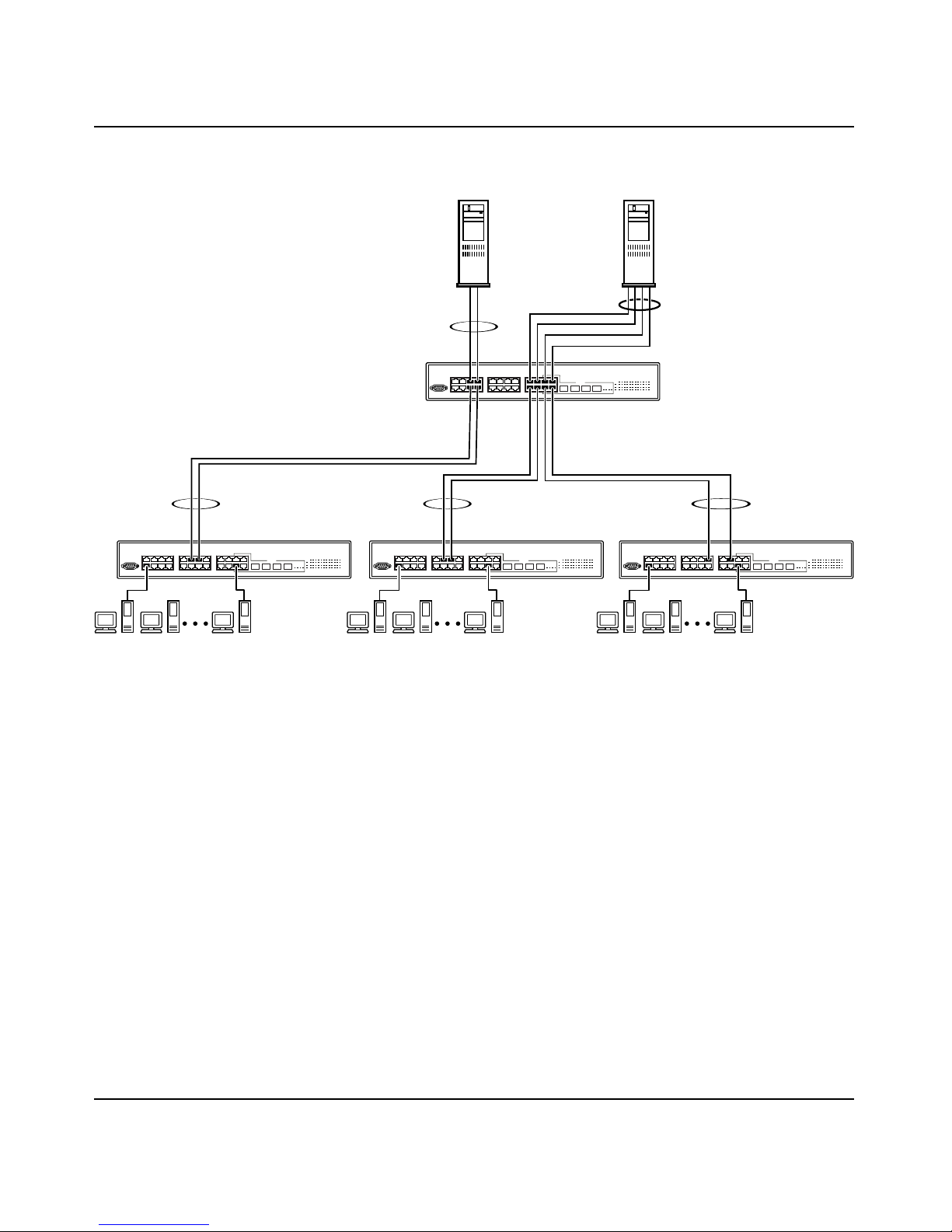
Figure 32 Client/server configuration example
Chapter 2 Network configuration 77
FS1
T2
S1
T3 T4
BayStack 380
FS2
T1
BayStack
380
T5
S4 BayStack 380S3 BayStack 380S2
10487EA
The trunk configuration screens for switches S1 to S4 are shown in “Trunk
configuration screen examples” following this section. For detailed information
about configuring trunks, see “MultiLink Trunk Configuration screen” on
page 138.
Using the BayStack 380 10/100/1000 Switch
Page 78

78 Chapter 2 Network configur ati on
Split Mult iLi n k Trunks
This section provides an example of a split MultiLink Trunk. To use split MLT,
you must disable spanning tree on the BayStack 380 switch.
Figure 33 shows an example of a split MultiLink Trunk:
Figure 33 Split MultiLink Trunk
BayStack 380
Trunk configuration screen examples
212859-A
Passport 8600 switch
Passport 8600 switch
10716EA
This section shows examples o f the Mu ltiLink T runk conf igurati on screen s for the
client/server configuration example shown in Figure 32. The screens show how
you could set up the trunk configuration screens for switches S1 to S4. See
“Spanning tree consi derations for Mul ti Lin k Trunks” on page 87, and “MultiLink
Trunk Configuration screen” on page 138 for more information.
Page 79

Chapter 2 Network configuration 79
Trunk configuration screen for Switch S1
Switch S1 is set up with five trunk configurations: T1, T2, T3, T4, and T5.
To set up the S1 trunk configuration:
Choose MultiLink Trunk Configuration (or press t) from the MultiLink
Trunk Configuration Menu screen (Figure 34).
Figure 34 Choosing the MultiLink Trunk Configuration Menu screen
Using the BayStack 380 10/100/1000 Switch
Page 80

80 Chapter 2 Network configur ati on
The MultiLink Trunk Configuration Menu screen opens (Figure 35).
Figure 35 MultiLink Trunk Configuration screen
Switch S1 is configured as follows:
• Trunk (read only) indicates the trunks (1 to 6) that correspond to the switch
ports specified in the Trunk Members fields.
• Trunk Members indicates the ports that can be configured, in each row, to
create the corresponding trunk:
— Ports 17, 19, 21, and 23 are assigned as trunk members of trunk 1.
— Ports 5 and 7 are assigned as trunk members of trunk 2.
— Ports 6 and 8 are assigned as trunk members of trunk 3.
— Ports 18 and 20 are assigned as trunk members of trunk 4.
— Ports 22 and 24 are assigned as trunk members of trunk 5.
Note: Assigning ports across the 12 port groups is not recommended.
For example, do not assign ports 11 and 14 as members of trunk 6.
212859-A
Page 81

Chapter 2 Network configuration 81
• STP Learning indicates the spanning tr ee partici pation set ting for eac h of the
trunks:
— Trunks 1 through 4 are enabled for Normal STP Learning.
— Trunk 5 is enabled for Fast STP Learning.
• Trunk Mode (read only) indicates the Trunk Mode for each of the trunks.
The Trunk Mode field values for trunks 1 to 6are set to Basic. Source MAC
addresses are statically assigned to specific trunk members for flooding and
forwarding, which allows the switch to stabilize and distribute the data
streams of source addresses across the trunk members.
• Trunk Status indicates the Trunk Status for each of the trunks. When set to
Enabled, the configuration settings for tha t specific tr unk are acti vated.
• Trunk Name indicates optional fields for assigning names to the
corresponding config ured trunks.
The names chosen for this example provide meaningful information to the
user of this switch (for example, S1:T1 to FS2 indicates that Trunk 1, in
Switch S1, connects to File Server 2).
Trunk configuration screen for Switch S2
As shown in Figure 32 on page 77, Switch S2 is set up with two trunk
configurations (T2 and T3). Both trunks connect directly to Switch S1.
As in the previous screen examples, to set up a trunk configuration, choose
MultiLink Trunk Configuration from the MultiLink Trunk Configuration Menu
screen.
Using the BayStack 380 10/100/1000 Switch
Page 82

82 Chapter 2 Network configur ati on
Figure 36 shows the MultiLink Trunk Configuration screen for Switch S2.
Figure 36 MultiLink Trunk Configuration screen for Switch S2
Switch S2 is configured as follows:
• Trunk (read only) indicates the trunks (1 to 6) that correspond to the switch
ports specified in the Trunk Members fields.
• Trunk Members indicates the ports that can be configured, in each row, to
create the corresponding trunk:
— Ports 11 and 13 are assigned as trunk members of trunk 1.
• STP Learning indicates the spanning tr ee partici pation set ting for eac h of the
trunks. Trunks 1 and 2 are enabled for Normal STP Learning.
• T runk Mode (re ad only) indica tes the T runk Mode for e ach of the trunks . The
Trunk Mode field values for trunks 1 and 2 are set to Basic. Source MAC
addresses are statically assigned to specific trunk members for flooding and
forwarding, which allows the switch to stabilize and distribute the data
streams of source addresses across the trunk members.
• Trunk Status indicates the Trunk Status for each of the trunks. When set to
Enabled, the configuration settings for tha t specific tr unk are acti vated.
212859-A
Page 83

Chapter 2 Network configuration 83
• Trunk Name indicates optional fields for assigning names to the
corresponding config ured trunks.
The names chosen for this example provide meaningful information to the
user of this switch (for example, S2:T2 to S1 indicates that Trunk 1, in Switch
S2, connects to Switch 1).
Trunk Configuration screen for Switch S3
As shown in Figure 32 on page 77, Switch S3 is set up with one trunk
configuration (T4). This trunk connects directly to Switch S1.
As in the previous screen examples, to set up an interswitch trunk configuration,
choose MultiLink Trunk Configuration from the MultiLink Trunk Configuration
Menu screen.
Figure 37 shows the MultiLink Trunk Configuration screen for Switch S3.
Figure 37 MultiLink Trunk Configuration screen for Switch S3
Using the BayStack 380 10/100/1000 Switch
Page 84

84 Chapter 2 Network configur ati on
Switch S3 is configured as follows:
• Trunk (read only) indicates the trunk (1 to 6) that corresponds to the switch
ports specified in the Trunk Members fields.
• Trunk Members indicates the ports that can be configured, in each row, to
create the corresponding trunk.
— Ports 11 and 13 are assigned as trunk members of trunk 1.
• STP Learning indicates the spanning tr ee partici pation set ting for eac h of the
trunks. Trunk 1 is enabled for Normal STP Learning.
• T runk Mode ( read on ly) indicates the Trunk Mode for e ach of the trunks . The
Trunk Mode field val ue for t runk 1 is set to Bas ic. Sourc e MAC address es are
statically assigned to specific trunk members for flooding and forwarding,
which allows the switch to stabilize and distribute the data streams of source
addresses across the trunk members.
• Trunk Status indicates the Trunk Status for each of the trunks. When set to
Enabled, the configuration settings for tha t specific tr unk are acti vated.
• Trunk Name indicates optional fields for assigning names to the
corresponding config ured trunks.
Trunk Configuration screen for Switch S4
The names chosen f or this example prov ide meaningful infor m ati on to the user of
this switch (for example, S3:T4 to S1 indicates that Trunk 1, in Switch S3,
connects to Switch 1).
As shown in Figure 38, Switch S4 is set up with one trunk configuration (T5).
This trunk connects directly to Switch S1.
As in the previous screen examples, to set up a trunk configuration, choose
MultiLink Trunk Configuration from the MultiLink Trunk Configuration Menu
screen.
212859-A
Page 85

Chapter 2 Network configuration 85
Figure 38 shows the MultiLink Trunk Configuration screen for Switch S4.
Figure 38 MultiLink Trunk Configuration screen for Switch S4
Switch S4 is configured as follows:
• Trunk (read only) indicates the trunk (1 to 6) that corresponds to the switch
ports specified in the Trunk Members fields.
• Trunk Members indicates the ports that can be configured, in each row, to
create the corresponding trunk.
— Ports 15 and 19 are assigned as trunk members of trunk T5.
• STP Learning indicates the spanni ng tree parti cipati on setting fo r each of the
trunks. Trunk 1 is enabled for Normal STP Learning.
• T runk Mode (read on ly) indicates the T runk Mode for e ach of the trunks . The
Trunk Mode field val ue for t runk 1 is set to Bas ic. Sourc e MAC address es are
statically assigned to specific trunk members for flooding and forwarding,
which allows the switch to stabilize and distribute the data streams of source
addresses across the trunk members.
• Trunk Status indicates the Trunk Status for ea ch of the trunks. When it is se t
to Enabled, the configuration settings for that specific trunk are activated.
• Trunk Name indicates optional fields for assigning names to the
corresponding config ured trunks.
Using the BayStack 380 10/100/1000 Switch
Page 86

86 Chapter 2 Network configur ati on
The names chosen for this example provide meaningful information to the
user (for example, S4:T5 to S1 indicates that Trunk 1, in Switch S4, connects
to Switch 1 ).
Before you configure trunks
When you create and enable a trunk, the trunk members (switch ports) take on
certain setti ngs nec ess ary fo r corr ec t oper ation of the Mult iLink Trunking feature.
Before you configure your MultiLink Trunk, you must consider these settings,
along with specific configuration rules, as follows:
1 Read the configuration rules provided in the next section, “Spanning tree
considerations for MultiLink Trunks” on page 87.
2 Determine which switch ports (up to four) are to become trunk members (the
specific ports making up the trunk). A minimum of two ports are required for
each trunk.
Ensure that the chosen switch ports are set t o Enabled, using either the Port
Configuration scree n (see “Port Configuration screen” on page 131) or
network management.
Trunk member ports must have the same VLAN configuration.
3 All network cabling should be complete and stable before configuring any
trunks, to avoid configuration errors.
4 Consider how the existing spanning tree will react to the new trunk
configuration (see “Spanning tree considerations for MultiLink Trunks” on
page 87).
5 Consider how existing VLANs will be affected by the addition of a trunk.
6 After completing the above steps, see “MultiLink Trunk Configuration
screen” on page 138 for screen examples and field descriptio ns that will help
you configure your MultiLink Trunks.
212859-A
Page 87

Spanning tree considerations for MultiLink Trunks
The spanning tree Path Cost parameter is recalculated based on the aggregate
bandwidth of the trunk. Fo r exa mple, Figure 39 shows a four-p ort tr unk (T1) wi th
two port members operating at an aggregate bandwidth of 2.2 Gb/s, with a
comparable Path Cost of 4. When the Path Cost calculations for both trunks are
equal, the software chooses the trunk with the larger aggregate bandwidth (T1) to
determine the most efficient path.
Figure 39 Path Cost arbitration example
Chapter 2 Network configuration 87
Path Cost T1 = 1
Aggregate Bandwidth
S1
1000 Mb/s
1000 Mb/s
2 Gb/s
S2
BayStack
380
100 Mb/s
Path Cost T2 = 5
100 Mb/s
T1 T2
Aggregate Bandwidth
200 Mb/s
BayStack
380
10488EB
Using the BayStack 380 10/100/1000 Switch
Page 88

88 Chapter 2 Network configur ati on
The switch can also detect trunk member ports that are physically misconfigured.
For example, in Figure 40, trunk member ports 2, 4, and 6 of Switch S1 are
configured correctly to trunk member ports 7, 9, and 11 of Switch S2. The
Spanning T ree Port Configura tion screen for each switch shows the port state fie ld
for each port in the Forwarding state.
Figure 40 Example 1: correctly configured trunk
S1 Port Configuration screen
S1
BayStack
380
S2
T1
S2 Port Configuration screen
BayStack
380
10489EA
212859-A
Page 89

If Switch S2’s trunk member port 7 is physically disconnected and then
reconnected to port 9, the Spanning Tr ee Por t Conf iguration screen fo r Swit ch S1
changes to show port 6 in the Blocking state (Figure 41).
Figure 41 Example 2: detecting a misconfigured port
Chapter 2 Network configuration 89
S1 Port Configuration screen
S1
[Blocking]
BayStack
380
T1
S2
BayStack
380
S2 Port Configuration screen
10490EA
Using the BayStack 380 10/100/1000 Switch
Page 90

90 Chapter 2 Network configur ati on
Additional tips about the MultiLink Trunking feature
When you create a MultiLink Trunk, the individual trunk members (the specific
ports that make up the trunk) logically connect and react as a single entity. For
example, if you change spanning tree parameters for any trunk member, the
spanning tree parameters for all trunk members change.
All configured trunks are indicated in the Spanning Tree Configuration screen.
The Trunk field lists the active trunks, adjacent to the port numbers that
correspond to the specific trunk member for that trunk.
When a trunk is active, you can disable spanning tree participation using the
Trunk Configuration screen or using the Spanning Tree Configuration screen.
When a trunk is not active, the spanning tree participation setting in the Trunk
Configuration screen does not take effect until you set the Trunk Status field to
Enabled.
The trunk is also viewed by management stations as a single spanning tree port.
The spanning tree port is represented by the trunk member with the lowest port
number. For example, if ports 13, 14, 15, and 16 are trunk members of trunk T1,
the management station views trunk T1 as spanning tree port 13.
For more info rmation a bout usi ng the Mul tiLink Trunking feature, see “MultiLink
Trunk Configuration Menu screen” on page 136.
See also Appendix C, “Quick configuration f or MultiLink T runki ng,” on page 199
for a configuration flowchart that can help you use this feature.
212859-A
Page 91

Port mirroring
You can designate one of your switch ports to monitor ingress traffic on a single
specified switch port (port-based).
Figure 38 provides a sample Port Mirroring Configuration screen. Note that the
displayed screens do not show all of the screen prompts that precede some
actions.
For example, when you con figur e a swit ch for port mirror ing or when you mod ify
an existing port mirroring configuration, the new configuration does not take
effect until you respond [Yes] to the following screen prompt:
Is your port mirroring configuration complete? [ Yes ]
Chapter 2 Network configuration 91
Figure 42 Port Mirroring Configuration port-based screen example
Using the BayStack 380 10/100/1000 Switch
Page 92

92 Chapter 2 Network configur ati on
212859-A
Page 93

Chapter 3
Using the console interface
This chapter describes how to configure and manage the BayStack 380 Switch
using the menu-driven console interface (CI).
This chapter covers the following topics:
• “Accessing the CI menus and screens,” next
• “Using the CI menus and screens” on page 94
• “Main menu” on page 96
Accessing the CI menus and screens
93
You can access the CI menus and screens locally through a console terminal
attached to your BayStack 380 Switch, remotely through a dial-up modem
connection, or in-band through a Telnet session (see “Console port” on page 26).
You can connect your console cable into any BayStack 380 Switch.
Note: If you have a properly configured BootP server in your network,
it detects the IP address; you will not need to configure the IP address.
For information about SNMP, see your network management documentation.
Using the BayStack 380 10/100/1000 Switch
Page 94

94 Chapter 3 Using the console interface
Using the CI menus and screens
The CI menus and screens provide options that allow you to configure and
manage BayStack 380 switches. Help prompts at the botto m of each menu and
screen explain how to enter data in the highlighted field and how to navigate the
menus and screens.
The Console port default sett ings are : 960 0 baud with eight dat a bits , one stop bi t,
and no parity as the communications format, with flow control set to disabled.
Some options allow you to toggle among several possible values; other options
allow you to set or modify a parameter.
Navigating the CI menus and screens
Use the following methods to navigate the CI menus and screens.
To select a menu option:
1 Use the arrow keys to highlight the option name.
2 Press [Enter].
The option takes effect immediately after you press [Enter].
Alternatively, you can press the key corresponding to the underlined letter in
the option name. For example, to select the Sw
the main menu, press the w key. Note that the text characters are not
case-sensitive.
To toggle between values in a form:
1 Use the spacebar to highlight the value.
2 Press [Enter].
To clear a string field:
1 Position the cursor in the string field.
itch Configuration option in
212859-A
Page 95

2 Press [Ctrl]- K.
To return to the previous menu, press [Ctrl]-R.
To go to the ne xt screen in a series, pr ess [Ctrl]-N.
To return to the main menu at any time, press [Ctr l]-C.
Press [Backspace] to delete ent ered text.
Options that appear in brac ket s (f or example, [Enabled]) are user- set t abl e options.
Screen fields and descriptions
Figure 43 shows a map of the CI screens. The remainder of this chapter describes
the CI screens and their fields, beginning with the main menu.
Figure 43 Map of console interface screens
Chapter 3 Using the console interface 95
Main Menu
IP Configuration/Setup
SNMP Configuration
System Characteristics
Switch Configuration
Console/Comm Port Configuration
Display Hardware Units
Spanning Tree Configuration
TELNET Configuration
Software Download
Configuration File
Display Event Log
Reset
Reset to Default Settings
Logout
MAC Address Table
MAC Address-Based Security
VLAN Configuration
Port Configuration
High Speed Flow Control Configuration
MultiLink Trunk Configuration
Port Mirroring Configuration
Display Port Statistics
Clear Port Statistics
Spanning Tree
Display Spanning Tree Switch Setting
MAC Address Security Configuration
MAC Address Security Port Configuration
MAC Address Security Table
VLAN Configuration
VLAN Port Configuration
VLAN Display by Port
Traffic Class
Policy Configuration
Priority Configuration
MultiLink Trunk Configuration
MultiLink Trunk Utilization
BS45041F
Using the BayStack 380 10/100/1000 Switch
Page 96

96 Chapter 3 Using the console interface
The CI screens for your specific switch model will show the correct model name
in the main menu scr een ti tle an d the corr ec t number of ports a nd port t ypes in t he
Port Configuration screen.
Note: The field valu es shown in th e CI screens in this section are
provided as examples only.
Main menu
This section describes the options available from the CI main menu (Figure 44).
The CI screens and submenus for these options are described in the following
sections.
Note: Some menu options shown in this main menu example and in
other screen examples in this chapter may not appear on your screen,
depending on the switch options installed. However, the full menu
options are shown in the scr een examples and desc ribed in the f oll owi ng
sections.
Figure 44 Console interface main menu
212859-A
Page 97

Table 8 describes the CI main menu options.
Table 8 Console interface main menu options
Option Description
Chapter 3 Using the console interface 97
IP Configuration/
Setup...
SNMP Configuration...
System
Characteristics...
Switch Configuration...
Console/Comm Port
Configuration...
Displays the IP Confi guration/Setup screen (see “IP C onfiguration/Setup screen”
on page 99). This screen allows you to set or modify IP configuration
parameters.
Displays the SNMP Configuration screen (see “SNMP Configuration screen” on
page 104). This screen allows you to set or modify the SNMP read-only
community and read-write community strings, enable or disable the
authentication trap and the link Up/down trap, set the IP address of trap
receivers, and set the trap community strings.
Displays the System Characteristics screen (see “System Characteristics
screen” on page 106). This screen allows you to view switch characteristics,
including number of resets, power status, hardware and firmware version, and
MAC address. This screen also contains three user-configurable fields:
sysContact, sysName, and sysLocation.
Displays the Switch Configuration Menu screen (see “Switch Configuration
Menu screen” on page108). This menu provides the following configuration
options: MAC Address Ta ble, MAC Address-Based Security, VLAN
Configur ation, Port Configuration, MultiLink Trunk Configuration, Port Mirroring
Configuration, Display Port Statistics, Clear All Port Statistics, and Display
System Log.
Displays the Console/Comm Port Configuration screen (see “Console/Comm
Port Configuration screen” on page 149). This screen allows you to configure
and modify the console/Comm port parameters, including the console port
speed and password settings for the switch operation.
Spanning Tree
Configuration...
TELNET
Configuration...
Software Download... Displays the Software Download screen (see “Software Download screen” on
Configuration File Displays the Configuration File Download/Upload screen (see “Configuration
Displays the Spanning Tree Configuration Menu (see “Spanning Tree
Configur ation Menu screen” on page 155). This menu provides the following
options: Spanning Tree Port Configuration, Display Spanning Tree Switch
Settings.
Displays the TELNET Con figuration sc reen (see “TELNET Configuration screen”
on page 162). This screen allows you to set your switch to enable a user at a
remote console termi na l to co mm unicate with the BayStac k 380 Switc h as if the
console terminal were directly connected to it. You can have up to four active
Telnet sessions running at one time in a standalone switch.
page 164). This screen allows you to revise the BayStack 380 Switch software
image that is located in nonvolatile flash memory.
File Download/Upload screen” on page 168). This screen allows you to store
your switch configuration parameters on a TFTP server. You can retrieve the
configuration pa rameters for automati cally config uring a replacem ent switch with
the same configuratio n when required.
Using the BayStack 380 10/100/1000 Switch
Page 98

98 Chapter 3 Using the console interface
Table 8 Console interface main menu options (continued)
Option Description
Display System Log Displays the System Log screen (see “System Log screen” on page 147).
Reset Resets the switch with the current configuration settings. This option is followed
by a screen prompt that p recede s the actio n. Enter Yes to reset the switc h; ente r
No to abort the option:
• When you select this option , the swi tch rese ts, runs a self-t est, then display s
the Nortel Networks logo screen. Press [Ctrl]-Y to access the BayStack 380
Switch main menu.
Reset to Default
Settings
Resets the switch to the factory default configuration settings. This option is
followed by a screen prompt that precedes the action. Enter Yes to reset the
switch to the factory default configuration settings; enter No to abort the option:
• When you select this option , the swi tch rese ts, runs a self-t est, then display s
the Nortel Networks logo screen. Press [Ctrl]-Y to access the BayStack 380
Switch main menu.
Caution: If you choose the Reset to Default Settings option, all of your
configured settings will be replaced with factory default settings when
you press [Enter]
Achtung: Bei Auswahl des Befehls zur Rücksetzung auf die
Standardeinstellungen werden alle von Ihnen konfigurierten
Einstellungen durch die werkseitigen Standardeinstellungen ersetzt,
wenn Sie die Eingabetaste drücken.
Attention:
courante sera remplacée par la configuration usine dès que vous
appuierez sur [Entrée].
Precaución:
predeterminados, todos los valores de configuración se sustituirán por
las valores predeterminados en fábrica al pulsar [Intro].
Attenzione:
default, tutte le im postazioni con figurate verran no sostituit e dai default d i
fabbrica premendo il tasto [Invio].
Si vous restaurez la configuration usine, votre configuration
Si selecciona el comando Restaurar valores
Nel caso in cui si selezioni la reimpostazione dei valori di
Logout Allows a user in a Telnet session or a user working at a password-protected
console terminal to terminate the session.
212859-A
Page 99

IP Configuration/Setup screen
The IP Configuration/Setup screen (Figure 45) allows you to set or modify the
BayStack 380 Switch IP configuration parameters. Data that you enter in the
user-configurable fields takes effect as soon as you press [Enter].
To open the IP Configuration/Setup screen:
Choose IP Configuration/Setup (or press i) from the main menu.
Figure 45 IP Configuration/Setup screen
Chapter 3 Using the console interface 99
Table 9 describes the IP Configuration/Setup screen fields.
Note: The read-only fie lds in this scr een are updated based on the BootP
mode specified in the BootP Request Mode field. (See “Choosing a
BootP request mode” on page 102 for more information.)
Using the BayStack 380 10/100/1000 Switch
Page 100

100 Chapter 3 Using the console interface
Table 9 IP Configuration/Setup screen fields
Field Description
BootP Request
Mode
Configurable
In Use Column header for the read-only fields in this screen. The read-only data displayed in
Last BootP Column header for the read-only fields in this screen. The read-only data displayed in
In-Band Switch
IP Address
One of four modes of operation for BootP. (See “Choosing a BootP request mode” on
page 102 for details about the four modes.)
Default Value BootP Disabled
Range BootP Disabled, BootP When Need ed, BootP Always, BootP or Last
Address
Column header for the user-configurable IP configuration fields in this screen.
this column represents IP configuration that is currently in use.
this column represents IP configuration obtained from the last BootP reply received.
The in-band IP address of the switch.
Default Value 0.0.0.0 (no IP address assigned)
Range Four-octet dotted-d ecimal no tation, where eac h octet is represe nted
as a decimal value, between 0 and 255, separated by a decimal
point
Note:
In-Band Subnet Ma sk fiel d value i s not pre sent, the software pro vides a n
default value for the In-Ban d Subnet Mask field that i s based on th e class of the
IP address entered in the In-Band IP Address field.
When the IP address is entered in th e In-Band IP Add ress field , and the
in-use
212859-A
 Loading...