

Nortel BayStack 350, BayStack 350T-HD, BayStack 350F, BayStack 350T, BayStack 350F-HD Series Manual
Page 1

Software Release V3.0.0
Part No. 893-00992-E
January 2000
4401 Great America Parkway
Santa Clara, CA 95054
Using the Ba yStack 350 Series 10/100 Autosense Switch
Page 2

Copyright © 2000 Nortel Networks
All rights reserved. Printed in the USA. January 2000.
The information in this document is subject to change without notice. The statements, configurations, technical data,
and recommendations in this document are believed to be accurate and reliable, but are presented without express or
implied warranty. Users must take full respo nsib ility fo r th e ir app lica tio ns o f a ny products specified in this d ocume nt .
The information in this document is proprietary to Nortel Networks NA Inc.
Trademarks
NORTEL NETWORKS is a trademark of Nortel Networks Corporation.
Bay Networks and Optivity are registered trademarks an d Accelar, BayStack, EZ LAN, Optivity Campus, Optivity
Enterprise, StackProbe, and the Bay Networks logo are trademarks of Nortel Networks NA Inc.
Microsoft, MS, MS-DOS, Win32, Windows, and Windows NT are registered trademarks of Microsoft Corporation.
All other trademarks and registered trademarks are t he property of their respective owners.
Statement of Conditions
In the interest of improvi ng internal design, operational function, and/o r relia bi lity, Nortel Network s NA Inc. reserves
the right to make changes to the products described in this document without notice.
Nortel Networks NA Inc. does not assume any liability that may occur due to the use or application of the product(s)
or circuit layout(s) described her ein.
USA Requirements Only
Federal Communications Commission (FCC) Compliance Notice: Radio Frequency Notice
Note: This equipment has been tested and found to comply with the limits for a Class A digital device, pursuant to
Part 15 of the FCC rules. These limits are designed to provide reaso nable protection against harmful interferenc e
when the equipment is operated in a commercial environment. This equipment ge nerates, uses, and can radiate radio
frequency energy. If it is not installed and used in accordance with the instruction manual, it may cause harmful
interference to radio communications. Operation of this equipment in a residential area is likely to cause harmful
interference, in which case users will be required to take whatever measures may be necessary to correct the
interference at their own expense.
European Requirements Only
EN 55 022 Statement
This is to certify that th e Norte l Netw orks Ba yStack 350 switch is shi elded a gainst the ge neratio n of radio in terfere nce
in accordance with the application of Council Directive 89/336/EEC, Article 4a. Conformity is declared by the
application of EN 55 022 Class A (CISPR 22).
Warning: This is a Class A product. In a domestic env iron m ent, this product may cause radio interference, in which
case, the user may be required to take appropriate measures.
Achtung: Dieses ist ein Gerät der Funkst örgrenzwertklasse A. In Wohnbereichen können bei Betrieb dieses Gerätes
Rundfunkstörungen auftreten, in welchen Fällen der Benutzer für entsprechende Gegenmaßnahmen verantwortlich
ist.
Attention: Ceci est un produit de Classe A. Dans un environnement domestique, ce produit risque de créer des
interférences radioélectriques, il appartiendra alors à l’utilisateur de prendre les mesures spécifiques appropriées.
ii
893-00992-E
Page 3

EC Declaration of Conformity
This product conforms (or these products conform) to the provisions of Council Directive 89/336/EEC and
73/23/EEC. The Declaration of Conformity is available on the Nortel Networks World Wide Web site at
http://libra2.corpwest.baynetworks.com/cgi-bin/ndCGI.exe/DocView/.
Japan/Nippon Requirements Only
Voluntary Control Council for Interference (VCCI) Statement
Voluntary Control Council for Interference (VCCI) Statement
This is a Class A product based on the standard of the Voluntary Control Council for Interference by Information
Technology Equipment (VCCI). If this equipment is used in a domestic environment, radio disturbance may arise.
When such trouble occurs, the user may be required to take corrective actions.
Taiwan Requirements
Bureau of Standards, Metrology and Inspection (BSMI) Statement
Canada Requirements Only
Canadian Department of Communications Radio Interference Regulations
This digital apparatus (Ba yStack 3 50 swi tch) doe s not e xc eed the C lass A l imits f or radio -noise emissions from di gital
apparatus as set out in the Radio Interference Regulations of the Canadian Department of Communications.
Règlement sur le brouillage radioélectrique du ministère des Communications
Cet appareil numérique (BayStack 350 switch) respecte les limites de bruits radioélectriques visant les appareils
numériques de classe A prescrites dans le Règlement sur le brouillage rad ioélectrique du ministère des
Communications du Canada.
893-00992-E
iii
Page 4

Nortel Networks NA Inc. Software License Agreement
NOTICE: Please carefully read this license agre ement before copying or using the accompanying software or
installing the hardware unit with pre-enabled software (each of which is referred to as “Software” in this Agreement).
BY COPYING OR USING THE SOFTWARE, YOU ACCEPT ALL OF THE TERMS AND CONDITIONS OF
THIS LICENSE AGREEMENT. THE TERMS EXPRESSED IN THIS AGREEMENT ARE THE ONLY TERMS
UNDER WHICH NORTEL NETWORKS WILL PERMIT YOU TO USE THE SOFTWARE. If you do not accept
these terms and conditions, return the product, unused and in the original shipping container, within 30 days of
purchase to obtain a credit for the full purchase price.
1. License Grant. Nortel Networks NA Inc. (“Nortel Networks”) grants the end user of the Software (“Licensee”) a
personal, nonex clusive, nontransferable license : a) to us e the So ftw are eit her on a single c omputer o r, if applicable, on
a single authorized device identified by host ID, for which it was originally acquired; b) to copy the Software solely
for backup purposes in support of authorized use of the Software; and c) to use and copy the associated user manual
solely in support of authoriz ed use of th e Softwa re b y Licen see. Thi s license applies t o the So ftware o nly and d oes not
extend to Nortel Networks Agent software or other Nortel Networks software products. Nortel Networks Agent
software or other Nortel Networks software products are licensed for use under the terms of the applicable N ortel
Networks NA Inc. Software License Agreement that accompanies such software and upon payment by the end user of
the applicable license fees for such software.
2. Restrictions on use; reservation of rights. The Software and user manuals are protected under copyright laws.
Nortel Networks and/or its licensors retain all title and ownership in both the Software and user manuals, including
any revisions made by Nortel Networks or its licensors. Th e copyright notice must be r e produced and incl uded with
any copy of any portion of the Software or user manuals. Licensee may not modify, translate, decompile, disassemble,
use for any competitive analysis, reverse engineer, distribute, or create derivative works from the Software or user
manuals or any copy , in whole or in part. Except as expressly provided in this Agreement, Licensee may not copy or
transfer the Software or user manuals, in whole or in part. The Software and user manuals embody Nortel Networks’
and its licensors’ confidential and proprietary intellectu al pro p erty. Licensee shall not sublicense, assign, or ot herwise
disclose to any third party the Software, or any information about the operation, design, performance, or
implementation of the Software and user manuals that is confidential to Nortel Networks and its licensors; however,
Licensee may grant permission to its consultants, subcontractors, a nd agents to use the Softw are at Licensee’s facility,
provided they have agreed to use the Software only in accordance with the terms of this license.
3. Limited warranty . Nortel Networks warrants each item of Software, as delivered by Nortel Networks and properly
installed and operated on Nortel Networks hardware or other equipment it is originally licensed for, to function
substantially as described in its accompanying user m anual during its warranty period , which begins on the date
Software is first shipped to Licensee. If an y item of S oftware f ails to so function d uring its w arranty period, as the sole
remedy Nortel Networks will at its discretion provide a suitable fix, patch, or workaround for the problem that may be
included in a future Software release. Nortel Networks further warrants to Licensee that the media on which the
Software is provided will be free from defec ts in materials and wo rkman ship under no rmal use for a peri od of 90 da ys
from the date Software is first shipped to Licensee. Nortel Networks will replace defective media at no charge if it is
returned to Nortel Netw orks during the warranty period along with proof of the date of sh ipment. This warrant y does
not apply if the media has been damaged as a result of accident, misuse, or abuse. The Licensee assumes all
responsibility for selection of the Software to achieve Licensee’s intended results and for the installation, use, and
results obtained from the Software. Nortel Networks does not warrant a) that the functions contained in the software
will meet the Licensee’s requirements, b) that the Software will operate in the hardware or software combinations that
the Licensee may select, c) that the operation of the Software will be uninterrupted or error free, or d) that all defects
in the operation of the Softw are will be corrected . Nortel Network s is not obligate d to remedy an y Software defect that
cannot be reproduced with the latest Software release. These warranties do not apply to the Software if it has been (i)
altered, except by Nortel Networks or in accordance with i ts instructions; (ii) used in conj unction with another
vendor’s product, resulting in the de fect; or (iii) damaged by improper environment, abuse, misuse , accident, or
negligence. THE FOREGOING WARRANTIES AND LIMITATIONS ARE EXCLUSIVE REMEDIES AND ARE
IN LIEU OF ALL OTHER WARRANTIES EXPRESS OR IMPLIED, INCLUDING WITHOUT LIMITATION ANY
WARRANTY OF MERCHANTABILITY OR FITNESS FOR A PARTICULAR PURPOSE.
iv
893-00992-E
Page 5

Licensee is responsible for the security of its o wn d ata and in formatio n and fo r maintain ing ade quate pro cedures a part
from the Software to reconstruct lost or altered files, data, or programs.
4. Limitation of liability. IN NO EVENT WILL NORTEL NETW ORKS OR ITS LICENS OR S BE LIABLE FOR
ANY COST OF SUBSTITUTE PROCUREMENT; SPECIAL, INDIRECT, INCIDENTAL, OR CONSEQUENTIAL
DAMAGES; OR ANY DAMAGES RESULTING FROM INACCURATE OR LOST DATA OR LOSS OF USE OR
PROFITS ARISING OUT OF OR IN CONNECTION WITH THE PERFORMANCE OF THE SOFTWARE, EVEN
IF NORTEL NETWORKS HAS BEEN ADVISED OF THE POSSIBILITY OF SUCH DAMAGES. IN NO EVENT
SHALL THE LIABILITY OF NORTEL NETWORKS RELATING TO THE SOFTWARE OR THIS AGREEMENT
EXCEED THE PRICE PAID TO NORTEL NETWORKS FOR THE SOFTWARE LICENSE.
5. Government Licensees. This provision applies to a ll Softwa re and docum entation acquired d irectly or i ndirectly by
or on behalf of the United States Government. The Software and documentation are commercial products, licensed on
the open market at market prices, and were developed entirely at private expense and without th e use of any U.S.
Government funds. The license to the U.S. Government is granted only with restricted rights, and use, duplication, or
disclosure by the U.S. Government is subject to the restrictions set forth in subparagraph (c)(1) of the Commercial
Computer Software––Restricte d Rig hts cla u se o f FAR 52.227-19 and the limitations set out in this license for civilian
agencies, and subparagraph (c)(1)(ii) of the Rights in Technical Data and Computer Software clause of DFARS
252.227-7013, for agencies of t he Department of Defense or their successors, whichever is applicable.
6. Use of Software in the European Community. This provision applies to all Software acquired for use within the
European Community. If Licensee uses the Software within a country in the European Community, the Software
Directive enacted by the Council of European Communities Directive dated 14 May, 1991, will apply to the
examination of the Software to facilitate interoperability. Licensee agrees to notify Nortel Networks of any such
intended examination of the Software an d may procure support and assista nce from Nortel Networks.
7. Term and termination. This license is effective until terminated; howeve r, all of the restrictions with respect to
Nortel Networks’ copyright in the Software and user manuals will cease being effective at the date of expiration of the
Nortel Networks copyright; those restrictions relating to use and disclosure of Nortel Networks’ confidential
information shall continue in effect. Licensee may terminate this license at any time. The license will automatically
terminate if Licensee fails to comply with any of the terms and conditions of the license. Upon termination for any
reason, Licensee will immediat ely destroy or return to Nortel Networks the Software, user manuals, and all copies.
Nortel Networks is not liable to Licensee for damages in any form solely by reason of the termination of this license.
8. Export and Re-export. Licensee agrees not to export, directly or indirectly, the Software or related technical data
or information without first obtaining any required export licenses or other governmental approvals. Without limiting
the foregoing, Licensee, on behalf of itself and its subsidiaries and affiliates, agrees that it will not, without first
obtaining all export licenses and approvals required by the U.S. Government: (i) export, re-export, transfer, or divert
any such Software or technical data, or any direct product thereof, to any country to which such exports or re-exports
are restricte d or em b argoed under United State s e x port control laws and re gulations, or to any nation al or re sident of
such restricted or embargoed countries; or (ii) provide the Software or related technical data or information to any
military end user or for any military end use, including the design, development, or production of any chemical,
nuclear, or biological weapons.
9. General. If any provision of this Agreement is held to be invalid or unenf orceable by a court of competent
jurisdiction, the remainder of the provisions of this Agreement shall remain in full force and effect. This Agreement
will be governed by the laws of the state of California.
Should you have any questions concerning this Agreement, contact Nortel Netw orks, 4401 Great America Parkway,
P.O. Box 58185, Santa Clara, California 95054-8185.
LICENSEE ACKNOWLEDGES THAT LICENSEE HAS READ THIS AGREEMENT, UNDERSTANDS IT, AND
AGREES TO BE BOUND BY ITS TERMS AND CONDITIONS. LICENSEE FURTHER AGREES THAT THIS
AGREEMENT IS THE ENTIRE AND EXCLUSIVE AGREEMENT BETWEEN NORTEL NETWORKS AND
LICENSEE, WHICH SUPERSEDES ALL PRIOR ORAL AND WRITTEN AGREEMENTS AND
COMMUNICATIONS BETWEEN THE PARTIES PERTAINING TO THE SUBJECT MATTER OF THIS
AGREEMENT. NO DIFFERENT OR ADDITIONAL TERMS WILL BE ENFORCEABLE AGAINST NORTEL
NETWORKS UNLESS NORTEL NETWORKS GIVES ITS EXPRESS WRITTEN CONSENT, INCLUDING AN
EXPRESS WAIVER OF THE TERMS OF THIS AGREEMENT.
893-00992-E
v
Page 6

Page 7

Contents
Preface
Audience ......................................... ................................ ................................ .................xix
Organization ....................................................................................................................xix
Text Conventions .............................................................................................................xxi
Special Message Formats ........................................................................................xxii
Acronyms ........................... .......................... .......................... ......................... ................xxii
Related Publications ......................................................................................................xxiii
How to Get Help ............................................................................................................xxiv
Safety Messages
Safety Alert Message Format .........................................................................................xxv
Safety Alert Messages Used in This Guide ..................................................................xxvii
Chapter 1
Getting Started
Hardware ........................................................................................................................1-1
Front-Panel Components .........................................................................................1-2
Back-Panel Components ..........................................................................................1-4
Cooling Fans ............................................................................................................1-5
Features ..........................................................................................................................1-5
Security .................................................................................................................... 1-8
MAC Address-Based Security ...........................................................................1-9
RADIUS-Based and SNMP Security .................................................................1-9
Autosensing ...........................................................................................................1-10
MultiLink Trunking ....... ...... ....... ...... ....... ...... ....... ...... ....... ...... ...... ...........................1-10
Port Mirroring .........................................................................................................1-11
Flash Memory Storage .......................... ...... ....... ...... ....................................... ...... .1-11
BootP Automatic IP Configuration ..........................................................................1-12
SNMP MIB Suppor t ..... ...... ....... ...... ....... ...... ....... ...................................... ....... ...... .1-12
Configuration and Switch Management .................................................................1-13
893-00992-E
vii
Page 8

Network Configuration ..................................................................................................1-13
Power Workgroups .................................................................................................1-14
Power Workgroups and Shared Media Hub ...........................................................1-15
VLAN Workgroups .................................................................................................1-16
VLAN Configuration Screen Examples ............................................................1-20
Additional Tips About Configuring VLANs .......................................................1-23
MultiLink Trunks ................................................. ...... ....... ...... ...... ....... ...... ....... ...... .1 -24
Inter-Switch Trunk Configuration ........... ....... ...... ....... ...... ...... ....... ...... ....... ...... .1 -24
Server Trunk Configuration ..............................................................................1-26
Client/Server Configuration Utilizing MultiLink Trunks .....................................1-27
Trunk Configuration Screen Examples ............................................................1-29
Before Configuring Trunks ...............................................................................1-40
MultiLink Trunking Configuration Rules ....................................... ...... ....... ...... .1-41
Spanning Tree Considerations .........................................................................1-42
Additional Tips About the MultiLink Trunking Feature ......................................1-45
Port Mirroring (Conversation Steering) ..................................................................1-45
Port-Based Mirroring Configuration ...................................... ....... ...... ..............1-46
Address-Based Mirroring Configuration ..........................................................1-49
Port Mirroring Configuration Rules ..................................................................1-51
Quick-Start Procedures ................................................................................................1-51
Quick-Start to Installing the BayStack 350 Switch .................................................1-52
Quick-Start to Managing the BayStack 350 Switch ................................................1-53
Console/Service Port Interface ........................................................................1-53
SNMP Management Applications ................................... .................................1-54
Chapter 2
Installing the BayStack 350 Switch
Required Tools and Materials .........................................................................................2-1
Package Contents ..........................................................................................................2-2
Site Preparation ..............................................................................................................2-3
Hardware ........................................ ............. ............. ............. ............. ............. .........2-3
Software ................................... ....................................................................... .........2-4
Environment ................................... .......................................................................... 2-4
Installation ......................................................................................................................2-5
Surface Mounting .....................................................................................................2-5
Attaching the Mounting Brackets .......................................................................2-6
viii
893-00992-E
Page 9

Installing on a Table or Shelf ..............................................................................2-7
Wall Mounting ..........................................................................................................2-8
Before You Begin ...............................................................................................2-8
Wall Mounting the Model 350F and Model 350T ...............................................2-9
Rack Mounting .......................................................................................................2-10
Connecting Port Cables ................................................................................................2-13
RJ-45 Port Cables ..................................................................................................2-13
100BASE-FX Port Cables ......................................................................................2-14
Connecting Power .........................................................................................................2-15
Verifying the Installation ................................................................................................2-16
Chapter 3
Using the Console Interface
Console Interface ............................................................................................................3-1
Console/Service Port Cabling .........................................................................................3-2
Console Terminal Requirements ..............................................................................3-2
Modem Requirements ..................................................... ...... ...... ....... ...... ....... ...... ...3-2
Connecting to the BayStack 350 Switch Console/Service Port ...............................3-3
Accessing the CI Menus and Screens ............................................................................3-3
Using the CI Menus and Screens ...................................................................................3-4
Navigating the CI Menus and Screens .....................................................................3-5
Screen Fields and Descriptions ...............................................................................3-6
Main Menu ......................................................................................................................3-7
IP Configuration ................. ...... ....................................... ....... ...... ...... ....... ...... ....... ...... .3 -10
Choosing a BootP Request Mode ..........................................................................3-12
BootP When Needed .......................................................................................3-12
BootP Always ...................................................................................................3-12
BootP Disabled ................................................................................................3-13
BootP or Last Address .....................................................................................3-13
SNMP Configuration .......... ...... ....... ...... ....... ...... ....... ...... ....... ...... ...... ...........................3-14
SNMP Community Strings and Trap Addresses ....................................................3-16
SNMP Port Trap Enable/Disable Options ...........................................................3-18
System Characteristics ...... ...... ....... ...... ....... ...................................... ....... ...... ....... ...... .3-2 0
Switch Configuration .....................................................................................................3-22
MAC Address Table ................................................................................................3-24
MAC Address-Based Security ................................................................................3-26
893-00992-E
ix
Page 10

MAC Address Security Configuration ..............................................................3-28
MAC Address Security Table ...........................................................................3-31
Accelerator Keys for Repetitive Tasks ..............................................................3-32
VLAN Configuration ...............................................................................................3-34
Port Configuration ..................................................................................................3-36
MultiLink Trunk Configuration ......... ....... ...... ....... ...... ....... ...................................... .3-39
Inter-Switch Trunk Configuration ........... ....... ...... ....... ...... ...... ....... ...... ....... ...... .3 -41
Server Trunk Configuration ..............................................................................3-43
Trunk Utilization ...............................................................................................3-45
Port Mirroring Configuration ...................................................................................3-48
Rate Limiting Configuration ....................................................................................3-51
Port Statistics .........................................................................................................3-54
Console/Service Port Configuration .............................................................................3-58
Setting Security Passwords ..........................................................................................3-60
Spanning Tree Configuration ........................................................................................3-61
Spanning Tree Port Configuration ..........................................................................3-63
Display Spanning Tree Switch Settings ..................................................................3-65
TELNET Configuration .................................................................................................3-68
Software Download .......................................................................................................3-71
Configuration File .........................................................................................................3-74
Network Security ..........................................................................................................3-77
Display Event Log .........................................................................................................3-79
Excessive Bad Entries ...........................................................................................3-80
Write Threshold ......................................................................................................3-80
Reset ............................................................................................................................3-81
Reset to Default Settings ..............................................................................................3-82
Logout ................................ ................... .................... ................... ................... ..............3 -83
Chapter 4
Troubleshooting
LED Indications ..............................................................................................................4-2
Diagnosing and Correcting the Problem ......................... ....... ...... ...... .............................4-4
Port Connection Problems ..............................................................................................4-5
Autonegotiation Modes ............................................................................................4-5
Port Interface ............................................................................................................4-6
x
893-00992-E
Page 11

Appendix A
Technical Specifications
Environmental .......................... ................................. ................................ ..................... A -1
Electrical ............... ................................................................. ........................................ A- 1
Physical Dimensions ...................................................................................................... A-2
Performance Specifications ........................................................................................... A-2
Network Protocol and Standards Compatibility ............................................................. A-2
Data Rate ......................................................................................................................A-2
Interface Options ........................................................................................................... A-3
Safety Agency Certification ........................................................................................... A-3
Electromagnetic Emissions ........................................................................................... A-3
Electromagnetic Susceptibility ....................................................................................... A-3
Declaration of Conformity .............................................................................................. A-4
Appendix B
Server/Trunk Connections
Optimal Server/Trunk Connections ................................................................... B-1
Appendix C
Connectors and Pin Assignments
RJ-45 (10BASE-T/100BASE-TX) Port Connectors ........ ....... ...... ...... ....... ...... ....... ........C-1
MDI and MDI-X Devices ................................................................................................C-2
MDI-X to MDI Cable Connections ........................................................................... C-3
MDI-X to MDI-X Cable Connections ..... ...... ....... ...... ....... ...................................... .. C-4
DB-9 (RS-232-D) Console/Service Port Connector ....................................................... C-5
100BASE-FX Fiber Optic Port Connectors .................................................................... C-6
Appendix D
Default Settings
Appendix E
Sample BootP Configuration File
Index
893-00992-E
xi
Page 12

Page 13

Figures
Figure 1-1. BayStack 350 Series Autosense Switch ..................................................1-1
Figure 1-2. Front-panel components ..........................................................................1-2
Figure 1-3. Back-panel components ..........................................................................1-4
Figure 1-4. BayStack 350 Switch Security Feature ....................................................1-8
Figure 1-5. Configuring power workgroups ..............................................................1-14
Figure 1-6. Configuring power workgroups and a shared media hub ......................1-15
Figure 1-7. Port-based VLAN example ....................................................................1-16
Figure 1-8. VLANs spanning multiple switches ........................................................1-17
Figure 1-9. Multiple VLANs sharing resources .........................................................1-18
Figure 1-10. VLAN configuration spanning multip le BayStack 350 switches .............1-1 9
Figure 1-11. VLAN Configuration screen for switch SW1 ...........................................1-20
Figure 1-12. VLAN Configuration screen for switch SW2 ...........................................1-21
Figure 1-13. VLAN Configuration screen for switch SW3 ...........................................1-22
Figure 1-14. VLAN Configuration screen for switch SW4 ...........................................1-23
Figure 1-15. Inter-switch trunk configuration example ..................... ....... ...... ....... ...... .1 -25
Figure 1-16. Server trunk configuration example .......................................................1-27
Figure 1-17. Client/server configuration example .......................................................1-28
Figure 1-18. Choosing the Server Trunk Configuration screen ..................................1-29
Figure 1-19. Server Trunk Configuration screen for Switch SW1 ...............................1-30
Figure 1-20. Choosing the Inter-Switch Trunk Configuration screen ..........................1-31
Figure 1-21. Inter-Switch Tr un k Confi gu ration screen example ....... ....... ...... .............. 1 -32
Figure 1-22. VLAN Configuration screen example for switch SW1 (1 of 2) ................1-34
Figure 1-23. VLAN Configuration screen example for switch SW1 (2 of 2) ................1-35
Figure 1-24. Trunk Configuration screen for switch SW2 ...........................................1-36
Figure 1-25. Trunk Configuration screen for switch SW3 ...........................................1-37
Figure 1-26. Trunk Configuration screen for switch SW4 ...........................................1-39
Figure 1-27. Path cost arbitration example .................................................................1-42
Figure 1-28. Example 1: Correctly configured trunk .................................................1-43
Figure 1-29. Example 2: Detecting a misconfigured port ............................. ....... ...... .1-44
893-00992-E
xiii
Page 14

Figure 1-30. Port-based mirroring configuration example ..........................................1-47
Figure 1-31. Port Mirroring port-based screen example ............................................1-48
Figure 1-32. Address-based mirroring configuration example ...................................1-49
Figure 1-33. Port Mirroring address-based screen example ......................................1-50
Figure 1-34. Installation flowchart ..............................................................................1-52
Figure 2-1. Package contents .....................................................................................2-2
Figure 2-2. Attaching mounting brackets for a surface mount ....................................2-6
Figure 2-3. Attaching rubber footpads ........................................................................2-7
Figure 2-4. Wall mounting the Model 350F and Model 350T .....................................2-9
Figure 2-5. Attaching mounting brackets for a rack mount (standard method) .........2-11
Figure 2-6. Attaching mounting brackets for a rack mount (alternative method) ......2-11
Figure 2-7. Installing the BayStack 350 switch in an equipment rack .......................2-12
Figure 2-8. Connecting RJ-45 port cables ...............................................................2-13
Figure 2-9. Connecting 100BASE-FX port cables ....................................................2-14
Figure 2-10. Observing LEDs to verify proper operation ............................................2-16
Figure 3-1. Map of console interface screens ............................................................3-6
Figure 3-2. Console interface main menu ..................................................................3-7
Figure 3-3. IP Configuration screen .........................................................................3-10
Figure 3-4. SNMP Configuration Screen .............. ...... ....... ...... ...... ....... ...... ....... .......3 -14
Figure 3-5. SNMP Community Strin gs and Trap Addresses screen ........................ 3 -16
Figure 3-6. SNMP Port Link Up/Down Trap Option Screen ......................................3-18
Figure 3-7. System Characteristics screen ... ....... ...... ....... ...................................... .3-20
Figure 3-8. Switch Configuration Menu screen ........................................................3-22
Figure 3-9. MAC Address Table screen ....................................................................3-24
Figure 3-10. MAC Address Security Configuration Menu ..........................................3-26
Figure 3-11. MAC Address Security Configuration Screen ........................................3-28
Figure 3-12. MAC Address Security Table Screen .....................................................3-31
Figure 3-13. Model 350F-HD VLAN Configuration screen (1 of 2) .............................3-34
Figure 3-14. Model 350F-HD VLAN Configuration screen (2 of 2) .............................3-35
Figure 3-15. Model 350F-HD Port Configuration screen (1 of 2) ...............................3-36
Figure 3-16. Model 350F-HD Port Configuration screen (2 of 2) ...............................3-37
Figure 3-17. MultiLink Trunk Configuration Menu screen ...........................................3-39
Figure 3-18. Inter-Switch Tr un k Confi gu ration screen ......................................... ...... .3-41
Figure 3-19. Server Trunk Configuration screen ........................................................3-43
Figure 3-20. Trunk Utilization screen (1 of 2) .............................................................3-45
xiv
893-00992-E
Page 15

Figure 3-21. Trunk Utilization screen (2 of 2) .............................................................3-46
Figure 3-22. Port Mirroring Configuration screen .......................................................3-48
Figure 3-23. Model 350F-HD Rate Limiting Configuration screen (1 of 2) .................3-51
Figure 3-24. Model 350F-HD Rate Limiting Configuration screen (2 of 2) .................3-52
Figure 3-25. Port Statistics screen .............................................................................3-54
Figure 3-26. Console/Service Port Configuration screen ...........................................3-58
Figure 3-27. Spanning Tree Configuration Menu screen ............................................3-62
Figure 3-28. Model 350T Spanning Tree Port Configuration screen ..........................3-63
Figure 3-29. Spanning Tree Switch Settings screen ..................................................3-65
Figure 3-30. TELNET Configuration screen ...............................................................3-68
Figure 3-31. Software Download screen ....................................................................3-71
Figure 3-32. Configuration File Download/Upload Screen .........................................3-74
Figure 3-33. Radius Network Security Screen ...........................................................3-77
Figure 3-34. Event Log screen ..................................... ....... ...... ...... ...........................3-79
Figure 3-35. Sample event log entry showing excessive bad entries .........................3-80
Figure 3-36. Sample event log event exceeding the write threshold ..........................3-80
Figure 3-37. Self-Test screen after resetting the switch .............................................3-81
Figure 3-38. Self-Test screen after resetting the switch to factory default settings .....3-82
Figure 3-39. Password prompt screen .......................................................................3-83
Figure 4-1. LED locations ...........................................................................................4-2
Figure C-1. RJ-45 (8-pin modular) port connector ..................................................... C-1
Figure C-2. MDI-X to MDI cable connections ............................................................ C-3
Figure C-3. MDI-X to MDI-X cable connections ....................... ...... ....... ...... ....... ...... .. C-4
Figure C-4. DB-9 console/service port connector ......................................................C-5
Figure C-5. 100BASE-FX multimode fiber optic port connector ................................C-6
893-00992-E
xv
Page 16

Page 17

Tables
Table 1-1. Front-panel components ..........................................................................1-3
Table 1-2. Back-panel components ..........................................................................1-4
Table 2-1. Power-up sequence ...............................................................................2-16
Table 3-1. Console interface main menu commands ................................................3-7
Table 3-2. IP Configuration screen fields ................................................................3-11
Table 3-3. SNMP Configuration Menu Screen Options ................................... ....... 3 -15
Table 3-4. SNMP Configuration screen fields .........................................................3-17
Table 3-5. SNMP Port Link Up/Down Trap Option Screen Fields ...........................3-19
Table 3-6. System Characteristics screen fields .....................................................3-21
Table 3-7. Switch Configuration Menu Options .......................................................3-23
Table 3-8. MAC Address Table screen fields ..........................................................3-25
Table 3-9. MAC Address Security Configuration Menu Options ............................3-27
Table 3-10. MAC Address Security Configuration Screen Fields ............................3-29
Table 3-11. MAC Address Security Table Screen Fields .........................................3-32
Table 3-12. VLAN Configuration screen fields ..........................................................3-35
Table 3-13. Port Configuration screen fields .............................................................3-37
Table 3-14. MultiLink Trunk Configuration Menu Options .........................................3-40
Table 3-15. Inter-Switch Trunk Configuration screen fields ......................................3-42
Table 3-16. Server Trunk Configuration screen fields ..............................................3-44
Table 3-17. Trunk Utilization screen fields ...............................................................3-46
Table 3-18. Port Mirroring Configuration screen fields ..............................................3-49
Table 3-19. Monitoring Modes ..................................................................................3-50
Table 3-20. Rate Limiting Configuration screen fields ..............................................3-53
Table 3-21. Port Statistics screen fields ....................................................................3-55
Table 3-22. Console/Service Port Configuration screen fields ..................................3-58
Table 3-23. Determining Console Security Requirements ........................................3-60
Table 3-24. Determining TELNET Sessions Security Requirements ........................3-60
Table 3-25. Determing the Screen Values ................................................................3-61
Table 3-26. Spanning Tree Configuration Menu Options ..........................................3-62
893-00992-E
xvii
Page 18

Table 3-27. Spanning Tree Port Configuration screen fields .....................................3-64
Table 3-28. Spanning Tree Switch Settings parameters ...........................................3-66
Table 3-29. TELNET Configuration screen fields ......................................................3-69
Table 3-30. Software Download screen fields ...........................................................3-72
Table 3-31. LED indications during the software download process ....................... .3-7 3
Table 3-32. Configuration File Download/Upload Screen Fields ..............................3-75
Table 3-33. Parameters Not Saved to the Configuration File ....................................3-76
Table 3-34. RADIUS Network Security Screen Fields .............................................3-78
Table 4-1. LED indications ........................................................................................4-3
Table 4-2. Corrective actions ....................................................................................4-4
Table B-1. Optimal server/trunk connections ........................................................... B-1
Table C-1. RJ-45 port connector pin assignments ...................................................C-2
Table C-2. DB-9 console/service port connector pin assignments ........................... C-5
Table D-1. Factory default settings for the BayStack 350 switch .............................D-1
xviii
893-00992-E
Page 19

Audience
Preface
Congratulations on your purchase of the BayStack™ 350 switch, part of the
Nortel Networks
There are four versions of the BayStack 350 Series 10/100 Autosense Switch: the
Model 350F-HD, the Model 350 F, the Model 350T-HD, and the Model 350T. This
guide describes the f eatur es, use s, and i nstalla tion pr ocedur es for the fo ur mod els.
(Unless otherwise specified, the terms “BayStack 350 switch” and “switch” refer
to all four sw itch versions.)
™
BayStack 10/100 Switch line of communications products.
This guide is intended for network instal lers and system administrato rs who are
responsible for installing, configuring, or maintaining networks. This guide
assumes that you unders ta nd t he t ran smission and management protocols used on
your network.
Organization
This guide has four chapters, five appendixes, and an index:
If you want to: Go to:
Learn about the BayStack 350 switch and its key features.
chapter also describes the Quick-Start procedures for quick
access to the switch management features.
Install the BayStack 350 switch on a flat surface, in a 19-inch
equipment rack, on a wall, and to verify its operation
893-00992-E
This
Chapter 1
Chapter 2
(continued)
xix
Page 20

Using the BayStack 350 Series 10/100 Autosense Switch
If you want to: Go to:
Connect to the BayStack 350 switch Console/Service Port and
Chapter 3
learn how to use the console interface (CI) menus to configure
and manage the switch
Troubleshoot and diagnose problems with the BayStack 350
Chapter 4
switch, as indicated by the LEDs
View operational a nd environmental specifications that apply to
Appendix A
the BayStack 350 switch
View a table that lists model-specific port groups to use when
Appendix B
connecting MultiLink trunks to servers using a single media
access control (MAC) address. (These port groups provide
optimal throughput for switch to server connections.)
Learn more about the BayStack 350 switch connectors (ports)
Appendix C
and pin assignments
View a listing of the factory default settings for the BayStack
Appendix D
350 switch
View a sample BootP configuration file Appendix E
View an alphabetical listing of the topics and subtopics in this
Index
guide, with cross-references to relevant information
xx
893-00992-E
Page 21

Text Conventions
This guide uses the following text conventions:
Preface
bold text
Indicates command names and options and text that
you need to enter.
Example: Enter
Example: Use the
show ip {alerts | routes
dinfo
command.
}.
italic text Indicates file and directory names, new terms, book
titles, and variables in command syntax descriptions.
Where a variable is two or more words, the words are
connected by an underscore.
Example: If the command syntax is:
show at
valid_route
<
valid_route
>
is one variable and you substitute one value
for it.
screen text Indicates system output, for example, prompts and
system messages.
Example:
Set Trap Monitor Filters
[Enter] Named keys in text are enclosed in square brackets.
The notation [Enter] is used for the Enter key and the
Return key.
893-00992-E
[Ctrl]-C Two or more keys that must be pr essed simultaneously
are shown in text linked with a hyphen (-) sign.
xxi
Page 22
Using the BayStack 350 Series 10/100 Autosense Switch
Special Message Formats
This guide uses the following formats to highlight special messages:
Note:
A note is used to highlight information of importance or special interest.
Acronyms
Caution:
result in damage to the equipment.
Warning:
result in personal injury.
This guide uses the following acronyms:
AUI attachmen t unit interface
BootP Bootstrap Protocol
CSMA/CD carrier sense multiple access/collision detection
IP Internet P rotocol
ISO International Organization for Stan dardization
MAC media access control
MAU media access unit
A caution alerts the user to some action or set of conditions that could
A warning alerts the use r to some act ion or set of cond itions tha t could
xxii
MDI-X medium dependent interface crossover
PPP Point-to-Point Protocol
SNMP Simple Network Management Protocol
STP s hielded twisted pair
893-00992-E
Page 23

Related Publications
For more informat ion about using the BayStack 3 50 s w it ch, refer to the follo w ing
publication:
• Bay Networks Guide to Implementing BaySecure LAN Access for Ethernet
(Part number 345-1106A)
Describes Nortel Networks realtime security system that safeguards Ethernet
networks from unauthorized surveillance and intrusion.
You can print selected technical manuals and release notes free, directly from the
Internet. Go to support.baynetworks.com/library/tpubs/. Find the product for
which you need documentation. Then locate the specific category and model or
version for your hardw are or soft ware product . Usi ng Adobe Ac robat Re ader, you
can open the manuals and releas e notes, search for the sections you ne ed, and print
them on most standard printers.
You can download Acrobat Reader free from the Adobe Systems Web site,
www.adobe.com.
Preface
You can purchase selected documentation sets, CDs, and technical publications
through the collateral catalog. The catalog is located on the World Wide Web at
support.baynetworks.com/catalog.html and is divided into sections arranged
alphabetically:
• The “CD ROMs” section lists available CDs.
• The “Guides/Books” section lists books on technical topics.
• The “Technical Manuals” section lists available printed documentation sets.
893-00992-E
xxiii
Page 24

Using the BayStack 350 Series 10/100 Autosense Switch
How to Get Help
If you purchased a service contract for your Nortel Networks product from a
distributor or authorized reseller, contact the technical support staff for that
distributor or reseller for assistance.
If you purchased a Nort el Net wor ks s ervice pr ogram, c ontact one of the f ollowing
Nortel Networks Technical Solutions Centers:
Technical Solutions Center Telephone Number
Billerica, MA 800-2LANWAN (800-252-6926)
Santa Clara, CA 800-2LANWAN (800-252-6926)
Valbonne, France 33-4-92-96-69-68
Sydney, Australia 61-2-9927-8800
Tokyo, Japan 81-3-5402-7041
xxiv
893-00992-E
Page 25

Safety Messages
Übersetzter Sicherheitshinweis
Traduction des Messages de Sécurité
Traducción de los mensajes de seguridad
Messaggi relativi alla sicurezza
This section translates the safety alert messages used in this guide. Safety alert
messages notify users of unsafe actions or conditions that could lead to personal
injury or equipment damage.
Safety Alert Message Format
All safety alert message s are ta gged with an inter natio nal alert symbol. When you
see a safety alert in this guide, be sure to read and follow the in structions before
continuing with the procedure.
The safety alert messages in this guide appear in the following format:
Symbol Meaning (English, German, French, Spanish, Italian, Japanese)
Warning:
could result in personal injury.
Caution:
could result in damage to the equipment.
893-00992-E
A warning alerts the user to some action or set of conditions that
A caution alerts the user to some action or set of conditions that
xxv
Page 26
Using the BayStack 350 Series 10/100 Autosense Switch
Symbol Meaning (English, German, French, Spanish, Italian, Japanese)
Vorsicht: Dieser Sicherheitshinweis macht den Benutzer auf Maßnahmen
oder Bedingungen aufmerksam, die die Verletzung von Personen zur Folge
haben können.
Achtung: Dieser Sicherheitshinweis macht den Benutzer auf Maßnahmen
oder Bedingungen aufmerksam, die eine Beschädigung der Geräte zur Folge
haben können.
Avertissement: La mention A v ertisseme nt attire l' attention de l'utilisa teur sur
une action ou un ensemble de conditions pouvant causer des blessures
corporelles.
Attention: La mention Attention attir e l'atten tion de l'ut ilisateu r sur une action
ou un ensemble de conditions pouvant endommager l'équipement visé.
Advertencia: Un mensaje de advertencia avisa al usuario sobre una acción o
conjunto de condiciones que pueden causar daños personales.
xxvi
Precaución
Un mensaje de precaución avisa al usuario sobre alguna acción
:
o conjunto de condiciones que pueden dañar el equipo.
Avvertenza:
L'avvertenza indica all'utente la presenza di una o più
condizioni che possono causare lesioni fisiche.
Attenzione:
Questo messaggio indica all'utente la presenza di una o più
condizioni che possono causare danni alle apparecchiature.
893-00992-E
Page 27

Safety Alert Messages Used in This Guide
The following safety alert messages a re use d in this guide. Please read and follow
these instructions when you encounter them in the text.
Class A Product
Copyright page
Safety Messages
Caution:
This device is a Class A product. In a domestic environmen t, this
device can cause radio interference, in which case, the user may be required to
take appropriate measures.
Achtung:
Dieses Gerät ist ein Produkt der Klasse A. Bei Heiminstallationen
kann dieses Gerät Störungen des Rundfunkempfangs verursachen, wodurch
der Benutzer gegebenenfalls entsprechende Maßnahmen ergreifen muß.
Attention:
Appareil électrique de classe A pouvant causer des
radio-interférences en utilisation domestique et nécessiter, le cas échéant,
l'application de mesures correctives appropriées.
Precaución:
Este dispositivo es un producto de la Clase A. En un entorno
doméstico, este dispositivo puede producir interferencias de radio, en cuyo
caso, puede exig ir se al us uario que tome la s medi das de co rrecc ió n apropi adas.
Attenzione:
Questo dispositivo è un prodotto di Classe A. Se utilizzato in
ambiente domestico, può causare interferenze radio e, in tal caso, l'utente
dovrà prendere le opportune precauzioni.
893-00992-E
xxvii
Page 28

Using the BayStack 350 Series 10/100 Autosense Switch
Accumulated Weight (Wall Mount)
Page 2-1
Caution:
The screws and wall composition must be able to withstand the
weight of the devi ce, plus the addit ional weight of the atta ched net work cables
and power cords.
Achtung:
Schrauben und Wand müssen so beschaffen sein, daß sie dem
Gewicht des Geräts, zuzüglich des Gewichts der angeschlossenen Netzwerkund Netzstromkabel, standhalten können.
Attention:
Les vis de fixation et le mur doivent être capables de supporter le
poids du dispositif, ainsi que des câbles réseau et cordons qui y sont rattachés.
Precaución:
Los tornillos y la compos ición de la pare d debe n ser cap aces de
sostener el peso del dispositivo más el peso adicional de los cables de red y
cables de alimentación conectados.
Attenzione:
Le viti e la struttura a muro devono essere in grado di sostenere
il peso del dispositivo, oltre a quello dei cavi di rete e di alimentazione
collegati.
xxviii
893-00992-E
Page 29

Accumulated Weight (Shelf or Table Mount)
Page 2-3
Safety Messages
Caution:
When this device is installed in a stack on a shelf or tabletop, the
accumulated weight of the port cables increases with the height of the shelf or
tabletop.
Achtung:
Wenn dieses Gerät in einem Stapel auf einem Tisch oder einem
Regalboden installiert wird, erhöht sich das Gesamtgewicht der
Schnittstellenkabel mit der Höhe des Regalbodens oder Tisches.
Attention:
Si l'appareil est posé dans un rack ou sur une étagère, notez bien
que le poids du câblage réseau augmente avec la hauteur de l'installation.
Precaución:
Cuando este disposit ivo se instala api la do en un estante o sobre
una mesa, el peso acumulado de los cables de los puertos aumenta según la
altura del estante o de la mesa.
Attenzione:
Quando il dispositivo viene installat o in stack su un ripiano o su
un tavolo, il peso dei cavi connessi alle porte aumenta in proporzione
all'altezza del ripiano o del tavolo.
893-00992-E
xxix
Page 30
Using the BayStack 350 Series 10/100 Autosense Switch
Hazardous Electrical Current
Page 2-5
Warning:
To avoid bodily injury from hazardous electrical current, do not
connect the power cord until instructed to do so.
Vorsicht:
Um Verletzungsgefahr durch einen elektrischen Stromschlag
auszuschließen, schließen Sie das Netzstromkabel erst an, wenn Sie dazu
angewiesen werden.
Avertissement:
Pour éliminer tout risque d'électrocution, ne jamais
brancher le cordon avant le moment indiqué dans le mode d'emploi.
Advertencia:
A fin de e vit ar dañ os p ersona les de bid os a cor rient es el éctri cas
peligrosas, no conecte el cable de alimentación hasta que se le indique.
Avvertenza:
Per evitare lesioni fisiche dovute a scariche elettrich e
pericolose, non coll e gare il cavo di alimentazion e pri ma del mo mento indica to
nelle istruzioni.
xxx
893-00992-E
Page 31

Stacking Units in a Rack
Page 2-10
Safety Messages
Caution:
When mounting this device in a rack, do not stack units directly on
top of one another in the rack. Each unit must be secured to the rack with
appropriate mounting brac ket s. Mounting brack ets ar e not desig ned to suppo rt
multiple units.
Achtung:
Wenn Sie dieses Gerät in einem Gerätegestell installieren, stellen
Sie die Geräte nicht direkt aufeinander. Jedes Gerät muß mit entsprechenden
Halterungen im Gestell befestigt werden. Die Halterungen sind nicht dafür
konzipiert, mehrere Geräte zu tragen.
Attention:
Si cet appareil doit être e ncastré dans un rack, ne jamais empiler
directement plusieurs unités les unes sur les autres. Chaque unité doit être
correctement fixée avec les membrures appropriées. Les membrures ne sont
pas conçues pour supporter le poids d'unités multiples.
Precaución:
Al montar este dispositivo apilado con otros dispositivos, no
apile las unidades dir ectamente unas sobre otras. Cada unid ad se debe f ija r a la
estructura mediante los soportes de montaje adecuados. Los soportes de
montaje no están diseñados para soportar varias unidades.
Attenzione:
Se il dispositivo viene installato su una cremagliera, non
impilarlo su un altro dispositivo montato sulla cremagliera. Ciascuna unità
deve essere fissata alla cremagliera con le apposite staffe di montaggio. Tali
staffe non possono essere utilizzate per fissare più unità.
893-00992-E
xxxi
Page 32
Using the BayStack 350 Series 10/100 Autosense Switch
Hazardous Light Source
Page 2-14
Warning:
Fiber optic equipmen t can emit l aser or in frared l ight that can injur e
your eyes. Never look into an optical fiber or connector port. Always assume
that fiber optic cables are connected to a light source.
Vorsicht:
Glasfaserkomponenten können Laserlicht bzw. Infrarotlicht
abstrahlen, wodurch Ihre Augen geschädigt werden können. Schauen Sie
niemals in einen Glasfaser-LWL oder ein Anschlußteil. Gehen Sie stets davon
aus, daß das Glasfaserkabel an eine Lichtquelle angeschlossen ist.
Avertissement:
L’équipement à fibre optique peut émettre des rayons laser
ou infrarouges qui risquent d’entraîner des lésions oculaires. Ne jamais
regarder dans le port d’un connecteur ou d’un câble à fibre optique. Toujours
supposer que les câbles à fibre optique sont raccordés à une source lumineuse.
Advertencia:
Los equipos de fibra óptica pueden emitir radiaciones de láser
o infrarrojas que pueden dañar los ojos. No mire nunca en el interior de una
fibra óptica ni de un puerto de conexión. Suponga siempre que los cables de
fibra óptica están conectados a una fuente luminosa.
Avvertenza:
Le apparecchiature a fibre ottiche emettono raggi laser o
infrarossi che possono risul ta re dann osi per gli occhi. Non guarda re mai
direttamente le fibre ottiche o le porte di collegamento. Tenere in
considerazione il fatto che i cavi a fibre ottiche sono collegati a una sorgente
luminosa.
xxxii
893-00992-E
Page 33

Turning Off Power to the Unit
Page 2-15
Safety Messages
Warning:
Remova l of th e power cord is the only w a y to t urn off power to this
device. The power cord must always be connected in a location that can be
accessed quickly and safely in case of an emergency.
Vorsicht:
Die Stromzufuhr zu diesem Gerät kann nur durch Ziehen des
Netzstromkabels unterbrochen werden. Die Netzsteckdose, an die das
Netzstromkabel angeschlossen ist, muß sich stets an einem Ort befinden, der
bei einem Notfall schnell und einfach zugänglich ist.
Avertissement:
Le débranchement du cordon d'alimentation constitue le
seul moyen de mettre cet appareil hors tension. Le cordon d'alimentation doit
donc toujours êtr e branc hé dans u ne pri se a ccessi ble po ur f ac iliter la mise hor s
tension en cas d'urgence.
Advertencia:
La única forma de desconectar la alimentación de este
dispositivo es desenchufar el cable de alimentación. El cable de alimentación
siempre debe esta r conecta do en un a ubicaci ón que per mita a cceder al cable de
forma rápida y segura en caso de emergencia.
Avvertenza:
Estrarre il cavo di alimentazione è l'unico sistema per spegnere
il dispositivo. Il cavo di alimentazione deve essere sempre collegato in una
posizione che permetta l'accesso facile e sicuro in caso di emergenza.
893-00992-E
xxxiii
Page 34

Using the BayStack 350 Series 10/100 Autosense Switch
Reset to Default Settings Command
Page 3-9
Caution:
If you choose the Reset to Default Settings command, all of your
configured settings will be replaced with factory default settings when you
press [Enter].
Achtung:
Bei Auswahl des Befehls zur Rücksetzung auf die
Standardeinstellungen werden alle von Ihnen konfigurierten Einstellungen
durch die werkseitigen Standardeinstellungen ersetzt, wenn Sie die
Eingabetaste drücken.
Attention:
Si vous restaurez la configuration usine, votre configuration
courante sera remplacée par la configuration usine dès que vous appuierez sur
[Entrée].
Precaución:
Si selecciona el comando Restaurar valores predeterminados,
todos los valores de configuración se sustituirán por las valores
predeterminados en fábrica al pulsar [Intro].
Attenzione:
Nel caso in cui si selezioni la reimpostazione dei valori di
default, tutte le impostazioni configurate verranno sostituite dai default di
fabbrica premendo il tasto [Invio].
xxxiv
893-00992-E
Page 35

Choosing a Baud Rate
Page 3-59
Safety Messages
Caution:
If you choose a baud rate that doe s not matc h your console terminal
baud rate, you will lose communication with the configuration interface when
you press [Enter] . If co mmun icati on is los t, set your c ons ole te rminal to ma tch
the new service port setting.
Achtung:
Bei Auswahl einer Baudrate, die nicht mit der Baudrate des
Konsolenterminals übereinstimmt, geht die Kommunikation mit der
Konsole nschnitt stelle v erlore n, wenn Sie die Ei ngabeta ste drück en. Stell en Sie
in diesem Fall das Konsolenterminal so ein, daß es mit der neuen Einstellung
der Service-Schnittstelle übereinstimmt.
Attention:
Si vous sélectionnez un débit différent de celui de votre terminal,
vous perdrez le contact avec l'interface de votre console dès que vous
appuierez sur [Entrée]. Pour restaurer la communication, alignez le débit de
votre terminal sur le nouveau débit de votre port de service.
Precaución:
Si selecciona una velo cidad de trans misión que no coincide con
la velocidad de transmisión del terminal de la consola, perderá la
comunicación con el interfaz de la consola al pulsar [Intro]. Si se pierde la
comunicación, ajuste el terminal de la consola para que coincida con el nuevo
valor del puerto de servicio.
Attenzione:
Nel caso in cui si scelga una velocità di trasmissione non
corrispondente a quella del terminale della console, la comunicazione con
l'interfac cia dell a console cadrà pr emendo il tasto [In v io]. Se la comu nicazione
cade, impostare il terminale della console in modo tale che corrisponda alla
nuova impostazione della porta di servizio.
893-00992-E
xxxv
Page 36

Using the BayStack 350 Series 10/100 Autosense Switch
Changing Passwords
Page 3-60
Caution:
If you change the system-supplied default passwords, be sure to
write the new passwords down and kee p th em in a saf e pl ace . If you forget the
new passwords, you cannot access the console interface. In that case, contact
Bay Networks for help.
Achtung:
Wenn Sie di e für das System standa rdmäßig eingestellten
Paßwörter ändern, not ieren Sie sic h die neuen Paß wörter , und be wah ren Sie sie
an einem sicheren Ort auf. Falls Sie die neuen Paßwörter vergessen, können
Sie nicht mehr auf die Konsolenschnittstelle zugreifen. Wenden Sie sich in
diesem Fall an Bay Networks, um Unterstützung zu erhalten.
Attention:
Si vous changez les mots de passe par défaut du système,
assurez-vous de bien noter vos nouveaux mots de passe et de les conserver
dans un endroit sûr. Si vous perdez vos nouveaux mots de passe, vous ne
pourrez plus accéder à votre interface. Le cas échéant, veuillez contacter Bay
Networks.
Precaución:
Si modifica las contraseñas predeterminadas asignadas por el
sistema, asegúrese de anotar las nuevas contraseñas y guárdelas en un lugar
seguro. Si olvida las nuevas contraseñas, no podrá acceder al interfaz de la
consola. En ese caso, póngase en contacto con Bay Networks para obtener
ayuda al respecto.
Attenzione:
In caso di modifica delle password predefinite nel sistema,
assicurarsi di annotare le nuove password e di conservarle in un luogo sicuro.
Nel caso in cui le nuove password vengano dimenticate, non sarà possibile
accedere all'interfaccia della console. In tal caso, contattare la Bay Networks
per avere assistenza.
xxxvi
893-00992-E
Page 37

Interrupting a Software Download
Page 3-71
Safety Messages
Caution:
Do not interrupt power to the device during th e software d ownlo ad
process. If the power is interrupted, the firmware image can become corrupted.
Achtung:
Unterbrechen Sie die Stromzufuhr zum Gerät nicht, während die
Software heruntergeladen wird. Bei Unterbrechung der Stromzufuhr kann das
Firmware-Image beschädi gt werden.
Attention:
Ne pas couper l'alimentation de l'appareil pendant le chargement
du logiciel. En cas d'int erru ption, le pr ogramme r éside nt peu t êtr e endo mmagé.
Precaución:
No interrumpa la alimentación del dispositivo durante el
proceso de descarga del software. Si lo hace, puede alterar la imagen de la
programación (firmware).
Attenzione:
Non interrompere l'alimentazione elettrica al dispositivo durante
il processo di scaricamento del so ftware. In caso di interruzione, l'immagine
firmware potrebbe danneggiarsi.
893-00992-E
xxxvii
Page 38

Using the BayStack 350 Series 10/100 Autosense Switch
Removing the Top Cover
Page 4-1
Warning:
To avoid bodily injury from hazardous electrical current, never
remove the top cover of the device. There are no user-serviceable components
inside.
Vorsicht:
Um Verletzungsgefahr durch einen elektrischen Stromschlag
auszuschließen, nehmen Sie niemals die obere Abdeckung vom Gerät ab. Im
Geräteinnern befinden sich keine Komponenten, die vom Benutzer gewartet
werden können.
Avertissement:
Pour éviter tout risque d'électrocution, ne jamais retirer le
capot de l'appareil. Cet appareil ne contient aucune pièce accessible par
l'utilisateur.
Advertencia:
A fin de evitar daños personales por corrientes eléctricas
peligrosas, no desmonte nunca la cubierta superior de este dispositivo. Los
componentes internos no son reparables por el usuario.
Avvertenza:
Per evitare lesioni fisiche dovute a scariche pericolo se di
corrente, no n rimuovere mai il coperchio superiore del disp ositivo. I
componenti interni non possono essere manipolati dall'utente.
xxxviii
893-00992-E
Page 39

Hardware
Chapter 1
Getting Started
This chapter introduces the BayStack 350 Series 10/100 Autosense Switch and
provides network configuration examples. It also describes the Quick-Start
procedures, which allow you to quickly set up parameters to manage the switch
using the Simple Network Management Protocol (SNMP) or the console/service
port.
There are four versions of the BayStack 350 switch: the Model 350F-HD, the
Model 350F, the Model 350T-HD, and the Model 350T (Figure 1-1
BayStack Model 350F-HD
BayStack Model 350F
BayStack Model 350T-HD
BayStack Model 350T
Figure 1-1. BayStack 350 Series Autosense Switch
893-00992-E
Power
Diagnostics
Power
Diagnostics
Power
Diagnostics
Power
Diagnostics
25
Comm Port
13
12
26
123456
13 14
14
123456
123456
Comm Port
13
345678
15
14
15 16
78910
16
17
18
17
18
19
78910
9
10 11 12
20
21
78910
19
20 21 22
13
11
12
25
26
100
123456
F Dx
22
23
Activity
24
1314 15 16 17 18
350F-HD
11
12
25
26
100
123456
F Dx
Activity
350F
11
12
123456
23
24
1314 15 16 17 18
350T-HD
14 15
16
1 9 1011 12 1314 15 16
2345678
100
10
F
Dx
Activity
350T
7
8
19
20
10/100 Autosense Switch
7
8
10/100 Autosense Switch
7
19
10/100 Autosense Switch
10/100 Autosense Switch
).
9
10
11
12
100
10
F Dx
21
Activity
22
23
24
100
10
F Dx
Activity
9
10
11
12
100
10
F Dx
Activity
8
9
10
11
12
100
10
F Dx
20
21
Activity
22
23
24
100
10
F Dx
Activity
100
10
F Dx
Activity
7833FA
1-1
Page 40

Using the BayStack 350 Series 10/100 Autosense Switch
Front-Panel Components
This section describes the front-panel components of the BayStack 350 switches
(Figure 1-2
• The Model 350F-HD provides 24 autosense 10/100BASE-TX ports and two
100BASE-FX fiber optic ports.
• The Model 350F provides 12 autosense 10/100BASE-TX ports and two
100BASE-FX fiber optic ports.
• The Model 350T-HD provides 24 autosense 10/100BASE-TX ports.
• The Model 350T provides 16 autosense 10/100BASE-TX ports.
). For a description of each numbered component, see Table 1-1.
1
2
1 5
2
1
2
1
2
3 4
123456
13 14 15 161718
Power
Diagnostics
25 26
Comm Port
10
3 4
Power
Diagnostics
Power
Diagnostics
13 14
Comm Port
123456
123456
13 14 151617 18
10
Power
Diagnostics
789101112
19 20 21 22 23
BayStack Model 350F-HD front panel
789101112
BayStack Model 350F front panel
4
8
7
19
1110912
20 21 22 23 24
BayStack Model 350T-HD front panel
4
1312345678 10 11 129
14 15 16
BayStack Model 350T front panel
24
5
Activity
26
25
100
F Dx
14
13
100
F Dx
Activity
12345678
100
F Dx
Activity
789101112
123456
19 20 21 22 23 24
13 14 15 16 17 18
350F-HD
10/100 Autosense Switch
789101112
123456
350F 10/100 Autosense Switch
789101112
123456
19 20 21 22 23 24
13 14 15 16 17 18
350T-HD
10/100 Autosense Switch
91011121314 1516
10/100 Autosense Switch
350T
6
100
10
F Dx
Activity
100
10
F Dx
Activity
7
8
9
6
100
10
F Dx
Activity
7
8
9
6
100
10
F Dx
Activity
100
10
F Dx
Activity
7
8
9
6
100
1010
F Dx
Activity
7
8
9
7831EA
Figure 1-2. Front-panel components
1-2
893-00992-E
Page 41

Getting Started
Table 1-1. Front-panel components
Item Icon/Label Description
1 Power Power LED (green):
On: DC power is available to the switch’s internal circuitry.
2 Diagnostics Diagnostics LED (green):
On: The switch passed the self-test.
Blinking: A nonfatal error occurred during the self-test.
Off: The switch failed the self-test.
3 (por t numbers) 100BASE-FX fiber optic port connectors.
4 (por t numbers) 10BASE-T/100BASE-TX RJ-45 (8-pin modular) port connectors.
5 (port numbers) 100BASE-FX LED matrix.
6 100 100BASE-FX/TX port status LEDs (green):
On: The corresponding port is set to operate at 100 Mb/s.
Off: The link connection is bad or there is no connection to this port.
Blinking: The corresponding port is management disabled.
710
2
10BASE-T port status LEDs (yellow):
On: The corresponding port is set to operate at 10 Mb/s.
Off: The link connection is bad or there is no connection to this port.
Blinking: The corresponding port is management disabled.
8 F Dx Full-duplex po rt status LEDs (green):
On: The corresponding port is in full-duplex mode.
Off: The corresponding port is in half-duplex mode.
9 Activity Port activity LEDs (green):
Blinking: Indicates t he network act ivity le v el f or the c orrespond ing port.
A high level of network activity can cause LEDs to appear to be on
continuously.
10 Comm Port
3
Console/service port DB-9 (RS-232-D) serial port connector: Allows the attachment
of a console terminal device for accessing the console interface (CI) screens.
1
Require 100-ohm unshielded twisted pair (UTP) cable. The RJ-45 connectors are wired as MDI-X ports to connect end
stations without using crossover cables.
2
Not available on the fiber optic 100BASE-FX LED matrix.
3
The console/service port for the Model 350F and Model 350T, labeled RS232, is located on the back panel (see
“Back-Panel Components
” on page 1-4).
1
893-00992-E
1-3
Page 42

Using the BayStack 350 Series 10/100 Autosense Switch
Back-Panel Components
This section describes the back-panel components of the BayStack 350 switches
(Figure 1-3
• The console/service port for the Model 350F-HD and Model 350T-HD is
located on the front panel (see “
• The console/service port for the Model 350F and Model 350T is located on
the back panel.
).
Front-Panel Components” on page 1-2).
For a description of each numbered component, see Table 1-2
1
BayStack 350F-HD
M/N AL2012A01
BayStack Model 350F-HD/350T-HD back panel
1
BayStack 350T
M/N AL2012A01
BayStack Model 350F/350T back panel
Figure 1-3. Back-panel components
Table 1-2. Back-panel components
Item Icon/Label Description
.
3
2
RS232
3
7830EB
1 Manufacturing label: Lists the model number, serial number, MAC address, and
voltage ratin g.
2RS232
1
Console/service port DB-9 (RS-232-D) serial port connector: Allows the attachment
of a console terminal device for accessing the console interface (CI) screens.
3 AC power receptacle2: Accepts the AC power cord (supplied).
1
The console/service port for the Model 350F-HD, labeled Comm Port, is located on the front panel.
2
The AC power receptacle is mounted with the ground pin below on some early units. Later units are configured as
shown above. The receptacle is keyed and the AC power cord cannot be installed incorrectly.
1-4
893-00992-E
Page 43

Cooling Fans
Variable-speed cooling fans in the BayStack 350 switch provide cooling for the
internal components. When you install the switch, be sure to allow enough space
on both sides of the switch for adequate air flow.
Features
BayStack 350 switches provide wire-speed, 100BASE-TX/100BASE-FX
(Fast Ethernet) switching that allows high-performance, low-cost connections to
full-duplex and half-duplex 10 Mb/s and 100 Mb/s Ethernet local area networks
(LANs).
Based on advanced application-specific integrated circuit (ASIC) technology,
BayStack 350 switches can be cost effectively deployed in 10 Mb/s LANs.
BayStack 350 switches adjus t (auton egot iate) thei r port speed and duplex mode to
match the best service provided by connected stations, up to 100 Mb/s in
full-duplex mode. As per forman ce requ irements i ncrea se and 10 0 Mb/s LANs are
deployed, each port uses autosensing to support any combination of 10 Mb/s and
100 Mb/s Ethernet LANs.
Getting Started
893-00992-E
One of the many benefits provided by the BayStack 350 switch is that network
users can migrate from 10 Mb/s switching to 100 Mb/s switching using a single
product.
The BayStack 350 switch o ffers the following featu res:
• High-speed forwarding rate: 1.6 million packets per second (peak)
• Learning rate: 1.6 million addresses per second (peak)
• Spanning Tree Protocol (STP): Complies with IEEE 802.1D standard
• SNMP agent support for the following Management Information Bases
(MIBs):
-- Bridge MIB (RFC 1493)
-- Ethernet MIB (RFC 1643)
-- Proprietary MIBs
-- RMON MIB (RFC 1757)
-- MIB-II (RFC 1213)
1-5
Page 44

Using the BayStack 350 Series 10/100 Autosense Switch
• Configuration Fil e download/upload support: Allows you to store your swi tch
configuratio n parameter s on a TFTP ser ver. Y ou can retr ie ve t he conf igura tion
parameters for automatically configuring a replacement switch or other
switches.
• Security:
-- MAC address-based security: Allows you to limit access to the switch
based on MAC addresses.
-- RADIUS network security: Allows you to set up your switch with
RADIUS-based (Remote Authentication Dial-In User Services) security,
for authenticating TELNET logins.
-- SNMP security: All ows you to limit administration access to the switch vi a
IP filtering.
• Rate limiting: Adjustable broadcast and multicast packet-rate limits for
control of broadcast and multicast storms
• Store-and -forward swit ch: Full-performance forwarding at full line speed
• Console/service port: Allows users to configure and manage the switch
locally or remotely
1-6
• TELNET:
-- Support for up to four simultaneous TELNET sessions
-- Optional password protection
-- Login time-out
-- Failed-logi n guard
-- Inactivity time-out
-- Allowed source addresses
-- Event logging
• IEEE 802.3u-compliant autonegotiation ports, with four modes:
-- 10BASE-T half-duplex
-- 10BASE-T full-duplex
-- 100BASE-TX half-duplex
-- 100BASE-TX full-duplex
893-00992-E
Page 45

Getting Started
• MultiLink Trunking
-- Inter-switch trunks
-- Server based trunks
• Remote monitoring (RMON), with four groups integrated:
-- Statistics
-- History
-- Alarms
-- Events
• Port-based virtual LANs (VLANs)
• Port Mirroring
-- Port-based
-- MAC address-based
• Front-panel light emitting diodes (LEDs) to monitor the following:
-- Power status
893-00992-E
-- System status
-- Port status for the following:
- 100 Mb/s link
- 10 Mb/s link
- Half- and full-duplex transmission
- Tx/Rx activity
- Managemen t enable/disa ble
• Upgradeable device firmware in nonvolatile flash memory using the Trivial
File Transfer Protocol (TFTP)
1-7
Page 46

Using the BayStack 350 Series 10/100 Autosense Switch
Security
Your BayStack 350 switch security feature can provide three levels of security for
your local area network (LAN):
• MAC address-based security -- Limits access to the switch based on allowed
source MAC addresses.
• RADIUS-based security -- Limi ts administrative ac ces s t o the switch through
user authentication.
• SNMP security -- Limits administration access via IP filtering.
Figure 1-4
This example assumes that the administration and teachers offices (and the
switches) are physically secured. In this configuration, the student VLAN (V2) is
denied access to ports occupied by VLANs V1, V3, and V1 + V3. Only students
who are authorized (as specified by the MAC address-based security feature) can
access the switch on the secured ports.
Legend
MAC address-based
security disabled for
(VLANs): V1, V3, V1+V3
MAC address-based
security enabled for
(VLAN) V2
V1
V2
V3
V1+V3
shows a typical campus VLAN configuration using security features.
RADIUS server
To network
center
F
BayStack 350
V1
Administration
BayStack 350
V2
Students
Grades
Library
RADIUS-based and
SNMP security
Teachers
V1+V3
V3
BS35076A
Figure 1 -4. BayStack 350 Switch Security Feature
1-8
893-00992-E
Page 47

Getting Started
MAC Address- Based Security
The MAC address-based security feature allows you to set up network access
control, based on source M AC addresses of authorized st ation s. You can specify a
range of system responses to unauthorized access, which can range from sending
a trap to disabling the intruder port. You can create a list of up to 98 MAC
addresses and specif y which addres ses are auth orize d or not author ized to conne ct
to the switch. You can also s pecif y which of the switc h po rts each MAC address is
allowed to access. The options for allowed port access include: NONE, ALL, and
single or multiple ports that are specified in a list, for example, 1-4, 6, 9, etc.
The MAC address -bas ed Secur ity fe ature is based on Nortel Netw or ks BaySecur e
LAN Acces s for Ethernet, a real-ti me security system that safeguards Ethernet
networks from unauthorized surveillance and intrusion. To learn more about the
Nortel Networks BaySecure LAN Access for Ethernet, refer to the Bay Networks
Guide to Implementing BaySecure LAN Access for Ethernet (Part number
345-1106A).
You must also include the MAC address of any router connected to any
Note:
secure ports.
893-00992-E
You can also specify optional actions to be exercise d by the switch if the softw ar e
detects a securit y violatio n. The response can be to sen d a trap, turn on destinati on
address (DA) filtering, disable the specif ic por t, or any combination of t hese three
options. For instructions on using the console interface (CI) to set up network
access control, see “MAC Address-Based Security” on page 3-26.
RADIUS-Based and SNMP Security
The RADIUS-based and SNMP security features allows you to set up network
access control, using t he RADIUS (Remot e Authenti cation Dial-In User Service s)
security protocol and selective IP filtering. The RADIUS-based security feature
uses the RADIUS protocol to a uthentic ate TELNET logi ns. SNMP-based se curity
limits administration access to the switch, based on IP address filters.
For instructions on using the console interface (CI) to set up the RADIUS-based
Security feature, see “Network Security” on page 3-77.
For instructions on using the console interface (C I) to set up SNMP Se cur it y , see
“TELNET Configuration” on page 3-68.
1-9
Page 48

Using the BayStack 350 Series 10/100 Autosense Switch
Autosensing
BayStack 350 switches are autosensing and autonegotiating devices. The term
autosense refers to a port’s ability to sense the speed of an attached device. The
term autonegotiation refers to a standardized protocol (IEEE 802.3u) that exists
between two IEEE 802.3u-capable devices. Autonegotiation allows the BayStack
350 switch to select the best of both speed and duplex modes.
Autosensing is use d whe n t he a tt ached device is not capable of autonegot iat i on or
is using a form of autonegotiation that is not compatible with the IEEE 802.3u
autonegotiation standard. In this case, because it is not possible to sense the
duplex mode of the attached device, the BayStack 350 switch reverts to
half-duplex mode.
When autonegotiation-capable devices are attached to the BayStack 350 switch,
the switch ports ne gotiate do wn from 100 Mb/s spe ed and full-duple x mode until a
supported speed and duplex mode is acknowledged by the attached device.
For more information about autosensing and autonegotiation modes, see
“Autonegotiation Modes” on page 4-5.
MultiLink Trunking
The MultiLink Trunking feature allows a user to group multiple ports (up to four)
together when forming a link to another switch or server, thus increasing
aggregate thr oughput of the interconnection bet w een two devices, up to 8 00 Mb/ s
in full-duplex mode. BayStack 350 switches can be configured with up to eight
MultiLink Trunks.
The switch supports a load balancing function that allows the switch to spread
traffic evenly across trunk members (ports that comprise a trunk), whenever
possible, to achieve the highest aggregate throughput. In addition, the MultiLink
Trunking software can detect misconfigured (or broken) trunk links. If this
happens, the software redirects all traffic on the misconfigured or broken trunk
member to other trunk members within that trunk.
The trunk members form a physical collection of ports that are treated as a single
logical link of higher bandwidth by the spanning tree protocol (STP) and the
learning, forwarding, and filtering functions.
For more information about the MultiLink Trunking feature, see “MultiLink
Trunks” on page 1-24.
1-10
893-00992-E
Page 49

Port Mirroring
The Port Mirro ring feature (sometimes referred to as conversation steering)
allows a user to designate a single switch port as a traffic monitor for up to two
specified ports or two media access control (MAC) addresses.
You can specify port-based monitoring, where a ll traffic on specified ports is
monitored, or address-based monitoring, where traffic between specified MAC
addresses is monitored.
Getting Started
You can attach a probe device (such as a Nortel Networks StackProbe
equivalent) to the designated monitor port. The designated port can monitor all
traffic on the network segment connected to the mirrored port. Error packets can
also be monitored and copied to the mirrored port for network troubleshooting.
For more information about the mirroring feature, see “Port Mirroring
(Conversation Steering)” on page 1-45.
Flash Memory Storage
The BayStack 350 switch uses flash memory to store the switch software image.
Flash memory a llows you to update the software ima ge with a newer versio n
without changing the switch hardware.
An in-band connection between the switch and the TFTP load host is required to
download the software image (see “Software Download” on page 3-71).
For information about connecting a console terminal for this procedure, see
“Console/Service Port Cabling” on page 3-2.
Note:
If a BootP server is set up properly on the network and the BayStack
350 switch detects a corrupted software image during the self-test, the switch
automatically uses TFTP to download a new software image.
™
, or
893-00992-E
1-11
Page 50

Using the BayStack 350 Series 10/100 Autosense Switch
BootP Automatic IP Configuration
The BayStack 350 switch has a unique 48-bit hardwar e a ddr ess , or MAC address,
that is printed on a label on the back panel. You use this MAC address when you
configure the network BootP server to recognize the BayStack 350 switch BootP
requests. A properly configured BootP server enables the switch to automatically
learn its assigned IP address, su bnet mask, IP ad dress of t he default router (d efaul t
gateway), and software image file name.
For an example of a BootP configuration file, see Appendix E, “Sample BootP
Configuration Fil e.”
SNMP MIB Support
The BayStack 350 switch supports an SNMP agent with private MIB extensions,
which ensur es compatibility with existing network management tools. The
BayStack 350 switch supports MIB-II (RFC 1213) and the RMON MIB
(RFC 1757), which pro vid e acces s to d etail ed manag ement st atis tics . With SNMP
management, you can conf igu re SNMP t raps ( on ind i vid ual por ts) t o be gen erated
automatically for cond itio ns such as an una uthor ized ac cess at temp t or chan ges in
a port’s operating status.
1-12
893-00992-E
Page 51

Configuration and Switch Management
The BayStack 350 switch is shipped directly from the factory ready to operate in
any 10BASE-T or 100BASE-TX standard network. You can manage the switch
using the Nortel Networks Optivity
®
generic SNMP-based network management software; however, you must assign
an IP address to the switch. You can set the switch’s IP address by using the
console/service port or BootP, which resides on the switch.
For more informat ion abou t using the conso le/servi ce port t o conf igure the swit ch,
see Chapter 3, “Using the Console Interface.”
Network Configuration
You can use BayStack 350 switches to connect workstations, personal computers
(PCs), and serv ers to each oth er b y connecti ng these de vices d irectly to the switch,
through a shared medi a hub that is conn ected to t he switch , or b y creat ing a virt ual
LAN (VLAN) through the switch.
Getting Started
network management software or any
This section provides five network configuration examples using BayStack 350
switches:
• Power workgroups
• Power workgroups and a shared media hub
• VLAN workgroups
• MultiLink trunks
• Port mirroring
Note:
All of the BayStack 350 switch models can be used interchangeably in
the following network configuration examples.
893-00992-E
1-13
Page 52
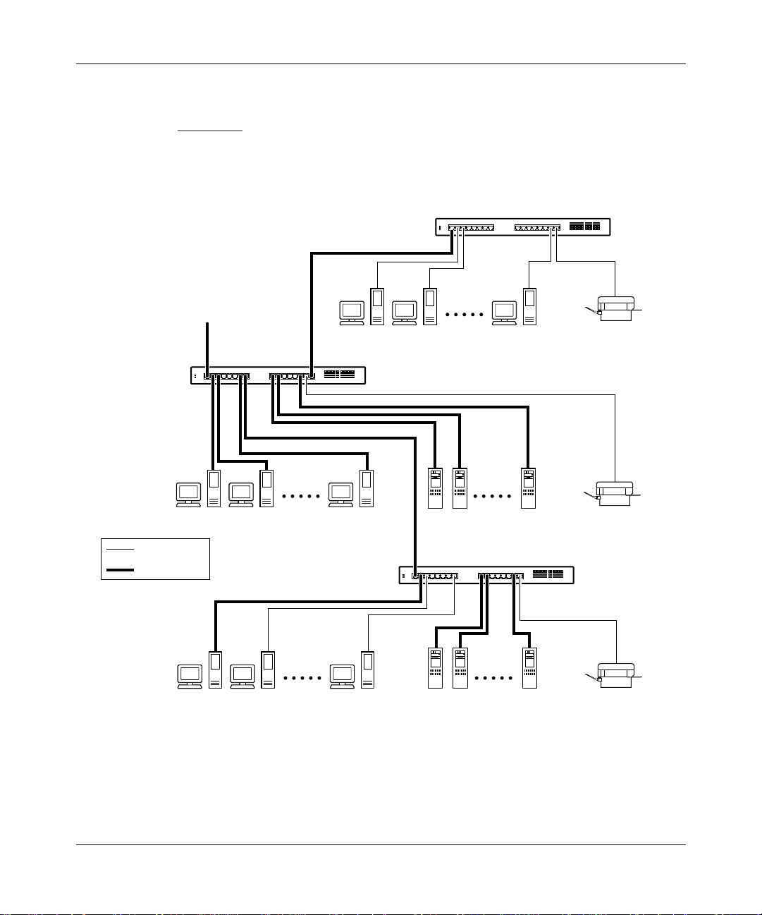
Using the BayStack 350 Series 10/100 Autosense Switch
Power Workgroups
Figure 1-5 shows BayStack 350 switches c onnecting dedi cated po wer wo rkgroups
and standard departmen tal us ers. I n this e xample, a ll users ha v e acc ess to 10 Mb/s
bandwidth or 100 Mb/s bandwidth on any port.
To
network
center
BayStack 350T switch
BayStack 350T switch
Key
10 Mb/s
100 Mb/s
Figure 1-5. Configuring power workgroups
1-14
BayStack 350T switch
620EA
893-00992-E
Page 53

Power Workgroups and Shared Media Hub
Figure 1-6 shows power workgroups connected to servers through BayStack 350
switches in a small network. Network managers who do not want to provide each
end station with the full 100 Mb/s bandwidth can designate a certain number of
users that share the full bandwidth provided by one of the switch ports. For
example, one workgroup is connected to a 10BASE-T shared media hub and
shares 10 Mb/s bandwidth provided by one of the BayStack 350 switch ports.
To
network
center
10BASE-T hub
BayStack 350T switch
Getting Started
Key
10 Mb/s
100 Mb/s
BayStack 350T switch
Figure 1-6. Configuring power workgroups and a shared media hub
893-00992-E
621EA
1-15
Page 54

Using the BayStack 350 Series 10/100 Autosense Switch
VLAN Workgroups
You can create and configure VLANs by segmenting BayStack 350 switches into
logical workgroups that are independent of each other. The workgroups can be
defined according to project or department.
Workgroup members on VLANs share computer resources but cannot
communicate with other workgroups; therefore access to specific servers is
restricted to all but the assigned workgroup. Broadcast packets are also confined
to a specific VLAN, which relieves traffic congestion (Figure 1-7
).
VLAN 1
FS1
SW1
Comm Port
Power
Diagnostics
Figure 1-7. Port-based VLAN example
VLAN 2
Activity
FS2
25
100
F Dx
123456
26
789101112
100
10
F Dx
350F-HD
19 20 21 22 23 24
10/100 Autosense Switch
Activity
100
10
F Dx
Activity
BS0021A
13 14 15 16 17 18
1-16
This same type of segmentation can be extended to multiple switches across the
network. Because BayStack 350 Series switches implement port-based VLANs,
extending VLANs to another switch requires utilizing a single switch port for
each VLAN (Figure 1-8
).
893-00992-E
Page 55
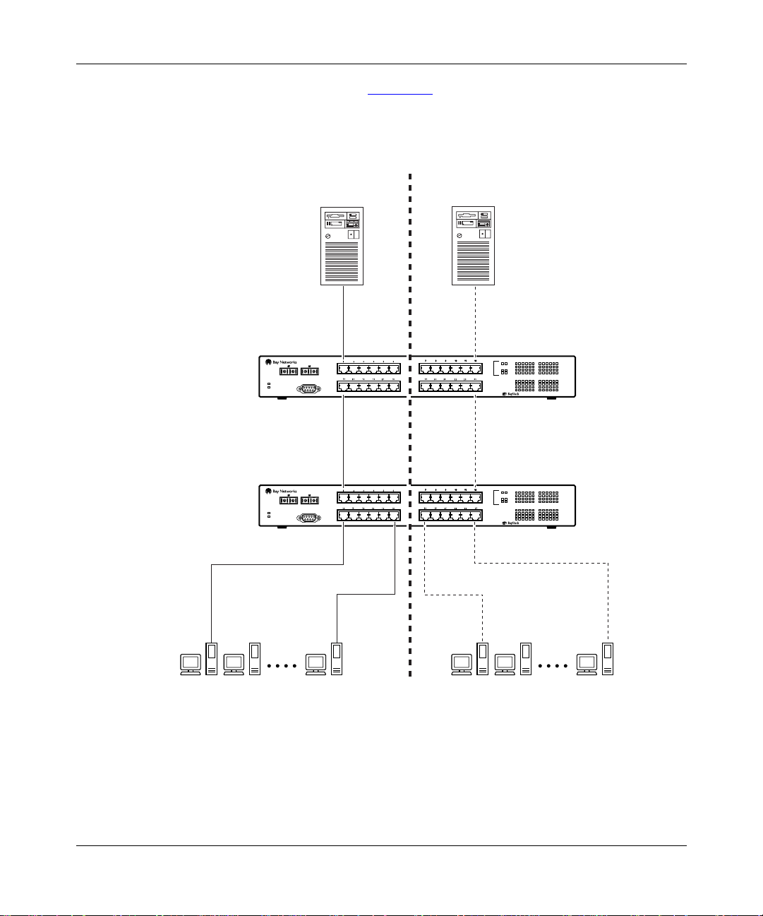
Getting Started
In this example conf i gurat ion ( Fig ure 1-8), spanning tree participatio n must b e set
to Disabled because the spanning tree protocol (STP) is not supported across
multiple VLANs (see “Spanning Tree Port Configuration” on page 3-63).
SW1
SW2
VLAN 1
FS1
Comm Port
Power
Diagnostics
Comm Port
Power
Diagnostics
VLAN 2
Activity
Activity
100
F Dx
100
F Dx
FS2
26
25
26
25
123456
13 14 15 16 17 18
350F-HD
123456
13 14 15 16 17 18
350F-HD
789101112
19 20 21 22 23 24
10/100 Autosense Switch
789101112
19 20 21 22 23 24
10/100 Autosense Switch
100
10
F Dx
Activity
100
10
F Dx
Activity
100
10
F Dx
Activity
100
10
F Dx
Activity
893-00992-E
BS0022A
Figure 1-8. VLANs spanning multiple switches
BayStack 350 switches a lso allow ports to exist in multiple VLA Ns for shared
resources, such as servers, printers, and switch-to-switch connections.
1-17
Page 56

Using the BayStack 350 Series 10/100 Autosense Switch
There are limitations when configuring multiple VLANs on a port and when
configuring VLA Ns that cross multiple swit ches. For example, to have multiple
VLANs that span multiple swit ches, no port sh ould be c onf igur ed to e xi st in mor e
than one VLAN in any of the switches. This method partitions the switches into
different, non-overlapping VLANs as shown previously in Figure 1-8
It is also possible to have resources exist in multiple VLANs on one switch as
shown in Figure 1-9
. In this example, clients on dif ferent broadca st domains share
resources. The br oad cas ts f rom por ts co nfigured in VLAN V1+V2 can be seen by
both VLAN V1 and VLAN V2 ports. Broadcasts from VLAN V1 ports can only
be seen by other VLAN V1 ports or VLAN V1+V2 ports. This analogy is also
true for ports that are assigned to VLAN V2.
SW1
BayStack 350T switch
V2V1
.
V1 + V2
V1 + V2
1-18
Key
VLAN V1
VLAN V2
VLAN V1 + V2
622EG
Figure 1-9. Multiple VLANs sharing resources
Figure 1-10 shows an example of how to connect switch ports , that a re configured
for multiple VLANs, to other switches.
Note:
When connecting switches that have ports configured for multiple
VLANs, the multiple VLANs do not get projected across the connection. The
connection is treated as a single VLAN at the other end.
893-00992-E
Page 57

Getting Started
As shown in Figure 1-10, switch SW1 is configured with multiple VLANs: ports
7, 15, and 16 are in VLAN V1; ports 2, 4, 10, and 14 are in VLAN V2; and ports
1, 11, and 12 are in VLAN V1+V2.
BayStack 350T switch
(VLAN V1 + V2)
SW4
BayStack 350T switch (VLAN V1)
SW2
V2
V1 + V2
V1 + V2
SW1
Key
100 Mb/s
VLAN V1
VLAN V2
VLAN V1 + V2
V1
BayStack 350T switch
(VLAN V1 + V2)
BayStack 350T switch (VLAN V2)
SW3
Figure 1-10. VLAN configuration spanning multiple BayStack 350 switches
Switch SW1 can connect to switch SW2 because all of the ports on switch SW2
are configured in a single VLAN (VLAN V1). The same is true for switch SW3
where all of the ports are configured in a single VLAN (VLAN V2). In both of
these cases, the connection port from switch SW1 matches the configuration of
the other switch. The con necti on to swi tch SW 4 is al so v al id bec ause, i n this case,
there is no longer a distinction between VLANs V1 and V2. VLAN V1+V2 is, in
effect, a single VLAN that contains both broadcast domains.
622EF
893-00992-E
1-19
Page 58

Using the BayStack 350 Series 10/100 Autosense Switch
Although switch SW4 is sho wn with all port s configur ed in VLAN V1+V2, any of
the ports can be assigned to additional VLANs as long as they are all in the sam e
VLAN membership as the connecting port (port 1).
VLAN Configuration Screen Examples
Figures 1-11
to 1-14 show examples of the VLAN Configuration screen settings
for switches SW1, SW2, SW3, and SW4.
The screen examples shown in this section show how the VLAN Configuration
screens appear when MultiLink trunking is not active (no trunks configured).
When MultiLink trunking is ac ti v e, onl y f ive VLANs can be conf ig ure d
Note:
and the VLAN Configuration screen shows only five VLAN columns. For
more information about the MultiLink Trunking feature, see “MultiLink
Trunks” on page 1-24.
VLAN Configuration
Port Trunk V1 V2 V3 V4 V5 V6 V7 V8
---- ----- ----- ----- ----- ----- ----- ----- ----- ---- 1 [ X ] [ X ] [ ] [ ] [ ] [ ] [ ] [ ]
2 [ ] [ X ] [ ] [ ] [ ] [ ] [ ] [ ]
3 [ ] [ ] [ ] [ ] [ ] [ ] [ ] [ ]
4 [ ] [ X ] [ ] [ ] [ ] [ ] [ ] [ ]
5 [ ] [ ] [ ] [ ] [ ] [ ] [ ] [ ]
6 [ ] [ ] [ ] [ ] [ ] [ ] [ ] [ ]
7 [ X ] [ ] [ ] [ ] [ ] [ ] [ ] [ ]
8 [ ] [ ] [ ] [ ] [ ] [ ] [ ] [ ]
9 [ ] [ ] [ ] [ ] [ ] [ ] [ ] [ ]
10 [ ] [ X ] [ ] [ ] [ ] [ ] [ ] [ ]
11 [ X ] [ X ] [ ] [ ] [ ] [ ] [ ] [ ]
12 [ X ] [ X ] [ ] [ ] [ ] [ ] [ ] [ ]
13 [ ] [ ] [ ] [ ] [ ] [ ] [ ] [ ]
14 [ ] [ X ] [ ] [ ] [ ] [ ] [ ] [ ]
15 [ X ] [ ] [ ] [ ] [ ] [ ] [ ] [ ]
16 [ X ] [ ] [ ] [ ] [ ] [ ] [ ] [ ]
Use space bar to display choices, press <Return> or <Enter> to select choice.
Press Ctrl-R to return to previous menu. Press Ctrl-C to return to Main Menu.
Figure 1-11. VLAN Configuration screen for switch SW1
1-20
893-00992-E
Page 59

Getting Started
VLAN Configuration
Port Trunk V1 V2 V3 V4 V5 V6 V7 V8
---- ----- ----- ----- ----- ----- ----- ----- ----- ---- 1 [ X ] [ ] [ ] [ ] [ ] [ ] [ ] [ ]
2 [ X ] [ ] [ ] [ ] [ ] [ ] [ ] [ ]
3 [ X ] [ ] [ ] [ ] [ ] [ ] [ ] [ ]
4 [ ] [ ] [ ] [ ] [ ] [ ] [ ] [ ]
5 [ ] [ ] [ ] [ ] [ ] [ ] [ ] [ ]
6 [ ] [ ] [ ] [ ] [ ] [ ] [ ] [ ]
7 [ ] [ ] [ ] [ ] [ ] [ ] [ ] [ ]
8 [ ] [ ] [ ] [ ] [ ] [ ] [ ] [ ]
9 [ ] [ ] [ ] [ ] [ ] [ ] [ ] [ ]
10 [ ] [ ] [ ] [ ] [ ] [ ] [ ] [ ]
11 [ ] [ ] [ ] [ ] [ ] [ ] [ ] [ ]
12 [ ] [ ] [ ] [ ] [ ] [ ] [ ] [ ]
13 [ ] [ ] [ ] [ ] [ ] [ ] [ ] [ ]
14 [ ] [ ] [ ] [ ] [ ] [ ] [ ] [ ]
15 [ X ] [ ] [ ] [ ] [ ] [ ] [ ] [ ]
16 [ X ] [ ] [ ] [ ] [ ] [ ] [ ] [ ]
Use space bar to display choices, press <Return> or <Enter> to select choice.
Press Ctrl-R to return to previous menu. Press Ctrl-C to return to Main Menu.
Figure 1-12. VLAN Configuration screen for switch SW2
893-00992-E
1-21
Page 60

Using the BayStack 350 Series 10/100 Autosense Switch
VLAN Configuration
Port Trunk V1 V2 V3 V4 V5 V6 V7 V8
---- ----- ----- ----- ----- ----- ----- ----- ----- ---- 1 [ ] [ ] [ ] [ ] [ ] [ ] [ ] [ ]
2 [ ] [ X ] [ ] [ ] [ ] [ ] [ ] [ ]
3 [ ] [ X ] [ ] [ ] [ ] [ ] [ ] [ ]
4 [ ] [ X ] [ ] [ ] [ ] [ ] [ ] [ ]
5 [ ] [ X ] [ ] [ ] [ ] [ ] [ ] [ ]
6 [ ] [ ] [ ] [ ] [ ] [ ] [ ] [ ]
7 [ ] [ ] [ ] [ ] [ ] [ ] [ ] [ ]
8 [ ] [ ] [ ] [ ] [ ] [ ] [ ] [ ]
9 [ ] [ ] [ ] [ ] [ ] [ ] [ ] [ ]
10 [ ] [ ] [ ] [ ] [ ] [ ] [ ] [ ]
11 [ ] [ ] [ ] [ ] [ ] [ ] [ ] [ ]
12 [ ] [ ] [ ] [ ] [ ] [ ] [ ] [ ]
13 [ ] [ ] [ ] [ ] [ ] [ ] [ ] [ ]
14 [ ] [ ] [ ] [ ] [ ] [ ] [ ] [ ]
15 [ ] [ X ] [ ] [ ] [ ] [ ] [ ] [ ]
16 [ ] [ X ] [ ] [ ] [ ] [ ] [ ] [ ]
Use space bar to display choices, press <Return> or <Enter> to select choice.
Press Ctrl-R to return to previous menu. Press Ctrl-C to return to Main Menu.
Figure 1-13. VLAN Configuration screen for switch SW3
1-22
893-00992-E
Page 61

Getting Started
VLAN Configuration
Port Trunk V1 V2 V3 V4 V5 V6 V7 V8
---- ----- ----- ----- ----- ----- ----- ----- ----- ---- 1 [ X ] [ X ] [ ] [ ] [ ] [ ] [ ] [ ]
2 [ X ] [ X ] [ ] [ ] [ ] [ ] [ ] [ ]
3 [ X ] [ X ] [ ] [ ] [ ] [ ] [ ] [ ]
4 [ ] [ ] [ ] [ ] [ ] [ ] [ ] [ ]
5 [ ] [ ] [ ] [ ] [ ] [ ] [ ] [ ]
6 [ ] [ ] [ ] [ ] [ ] [ ] [ ] [ ]
7 [ ] [ ] [ ] [ ] [ ] [ ] [ ] [ ]
8 [ ] [ ] [ ] [ ] [ ] [ ] [ ] [ ]
9 [ ] [ ] [ ] [ ] [ ] [ ] [ ] [ ]
10 [ ] [ ] [ ] [ ] [ ] [ ] [ ] [ ]
11 [ ] [ ] [ ] [ ] [ ] [ ] [ ] [ ]
12 [ ] [ ] [ ] [ ] [ ] [ ] [ ] [ ]
13 [ ] [ ] [ ] [ ] [ ] [ ] [ ] [ ]
14 [ ] [ ] [ ] [ ] [ ] [ ] [ ] [ ]
15 [ ] [ ] [ ] [ ] [ ] [ ] [ ] [ ]
16 [ X ] [ X ] [ ] [ ] [ ] [ ] [ ] [ ]
Use space bar to display choices, press <Return> or <Enter> to select choice.
Press Ctrl-R to return to previous menu. Press Ctrl-C to return to Main Menu.
Figure 1-14. VLAN Configuration screen for switch SW4
Additional Tips About Configuring VLANs
To group switch ports into logical workgroups, select the ports under the VLAN
name (V1, V2, ....., or V8) in the VLAN Configuration screen. If you want users
on different VLANs to share a port, select that port under each VLAN name.
You can create VLANs for one BayStack 350 switch, or you can create VLANs
that span multiple switches. However, each switch that participates i n the VLAN
configuration must be configured individually. You can also assign multiple
VLANs to a port connected to a server, which allows the server to be shared by
multiple logical workgroups.
You can only create five VLANs when the MultiLink Trunking feature is active.
The VLAN Configuration screen displays five VLAN columns when any trunk is
enabled.
893-00992-E
1-23
Page 62

Using the BayStack 350 Series 10/100 Autosense Switch
MultiLink Trunks
BayStack 350 switches support two types of trunking configurations:
• Inter-switch trunk configuration
• Server trunk configuration
You can choose the configuration type from the MultiLink Trunk Configuration
Menu screen (see “MultiLink Trunk Configuration” on page 3-39).
Inter-switch trunk configurations are designated as (trunks) I1 to I4 in the
Inter-Switch Trunk Configuration screen. Server trunk configurations are
designated as (trunks) S1 to S4 in the Server Trunk Configuration screen.
This trunk designation convention is also used in related screens that display
trunking information (for example, the VLAN Configuration screen).
Any combination of each configuration type (server trunk and inter-switch), can
be used to configure up to 16 trunk members on each switch).
Inter-Switch Trunk Configuration
1-24
You can use the Inter-Switch Trunk Configuration screen to create
switch-to-switch trunk links. This configuration type allows you to logically
connect up to eight switch ports together to form up to four trunks in any of the
following configurations:
• One trunk -- With the trunk configured with at least two trunk members, but
not more than fo ur.
• Two trunks -- With each trunk configured with at least two trunk members,
but not more than four.
• Three trunks -- W i th each t runk configured with at least two trunk member s,
but not more than four; the combined trunks cannot exceed eight trunk
members (see Note).
Note:
When you create a three trunk configuration, do not configure any two
of the trunks with three trunk members. That configuration is not supported.
• Four trunks -- With each trunk configured with two trunk members.
893-00992-E
Page 63

Getting Started
You can configure individual trunks between multiple switches as shown in
Figure 1-15
.
Although Figure 1-15
shows only two inter-switch trunks (I1 and I2) connecting
switch SW1 to switches SW2 and SW3, you can configure any BayStack 350
switch with up to four inter-switch trunks.
You can configure MultiLink trunks with up to four switch ports to provide up to
800 Mb/s aggregate bandwidth through each trunk, in full-duplex mode. As
shown in Figure 1-15
, when traffic between switch-to-switch connections
approaches single port bandwidth limitations, creating a MultiLink trunk can
supply the additional bandwidth required to improve the performance.
123456
26
25
789101112
13 14 15 16 17 18
350F-HD
19 20 21 22 23 24
10/100 Autosense Switch
100
10
F Dx
Activity
100
10
F Dx
Activity
SW2
100
F Dx
Comm Port
Power
Diagnostics
SW1
F
I1
Activity
F
123456
26
25
789101112
13 14 15 16 17 18
350F-HD
19 20 21 22 23 24
10/100 Autosense Switch
100
10
F Dx
Activity
100
10
F Dx
Activity
I2
100
F Dx
Comm Port
Power
Diagnostics
Activity
893-00992-E
Comm Port
Power
Diagnostics
SW3
Figure 1-15. Inter-switch trunk configuration example
123456
26
25
789101112
13 14 15 16 17 18
350F-HD
19 20 21 22 23 24
10/100 Autosense Switch
100
10
F Dx
Activity
100
10
F Dx
Activity
100
F Dx
Activity
6122ED
1-25
Page 64

Using the BayStack 350 Series 10/100 Autosense Switch
Server Trunk Configuration
Use the Server Trunk Configuration screen to connect switches to servers that
support multiport, single-MAC, network interface controllers (NICs).
Do not use the server trunk configuration screen to create
Note:
switch-to-switch tr unk links. Use th e inter -switch trunk con figur ation screen to
create switch- to-switch t runk links (see “ Inter -Switch T runk Conf iguration
page 1-24
).
You can logically connect up to eight switch ports together to create up to four
trunks in any of the following configurations:
• One trunk -- With the trunk configured with at least two trunk members, but
not more than fo ur.
• Two trunks -- With each trunk configured with at least two trunk members,
but not more than four.
• Three trunks -- W i th each t runk configured with at least two trunk member s,
but not more than four; the combined trunks cannot exceed eight trunk
members (see Note).
” on
1-26
When you create a three trunk configuration, do not configure any two
Note:
of the trunks with three trunk members. That configuration is not supported.
• Four trunks -- With each trunk configured with two trunk members.
When you use the Server T runk Conf ig uration scr een to connect a trunk
Note:
to a server that uses a single MAC address, set up your trunk members
according to the information provided in Appendix B, “Server/Trunk
Connections.”
893-00992-E
Page 65

Getting Started
Figure 1-16 shows a typical server trunk topology utilizing the server trunk
configurat ion. FS1 ut ili zes du al MAC addresses, usin g one MAC address for each
NIC. For this reason, FS1 does not require a trunk assignment. FS2 is a single
MAC server (with a four-port NIC) and is set up as a server trunk configuration
(S1).
In this configuration example, server trunk S1 is assigned trunk members that
correspond to the information provided in Appendix B, “Server/Trunk
Connections.” This allows the trunks to operate at optimal efficiency.
FS1
FS2
S1
SW1
Comm Port
Power
Diagnostics
789101112
26
25
123456
100
100
10
F Dx
F Dx
Activity
Activity
1920 21 22 2324
1314 15 16 1718
100
10
F Dx
Activity
350F-HD
10/100 Autosense Switch
BS0028A
Figure 1-16. Server trunk configuration example
Client/Server Configuration Utilizing MultiLink Trunks
Figure 1-17
shows an example of how MultiLink trunking can be used in a
client/server configuration.
In this example, both servers are connected directly to switch SW1. FS2 is
connected through a server trunk configuration (S1). The switch-to-switch
connections are through inter-switch trunks (I1, I2, I3, and I4).
893-00992-E
1-27
Page 66

Using the BayStack 350 Series 10/100 Autosense Switch
Clients accessing data from the servers (FS1 and FS2) are provided with
maximized bandwidth through server trunk S1 and inter-switch trunks I1, I2, I3,
and I4. Trunk members (the ports making up each trunk) do not have to be
consecutive switch ports; they can be selected randomly, as shown by I4.
With spanning tree enabled, one of the trunks (I1 or I2) acts as a redundant
(backup) trunk to s witch S W2. With spanning tr ee disabled, trunks I1 and I 2 must
be configured into separate VLANs for this configuration to function properly
(see “VLAN Workgroups
” on page 1-16).
I1
SW2
FS1
SW1
Comm Port
Power
Diagnostics
F
F
I2
SW3
789101112
25
26
123456
100
100
10
F Dx
F Dx
Activity
Activity
1920 21 22 2324
1314 15 16 1718
Comm Port
Power
Diagnostics
100
10
F Dx
Activity
350F-HD
10/100 Autosense Switch
Comm Port
Power
Diagnostics
FS2
I3
S1
789101112
25
26
123456
100
100
10
F Dx
F Dx
Activity
Activity
1920 21 22 2324
1314 15 16 1718
100
10
F Dx
Activity
350F-HD
10/100 Autosense Switch
Server trunk configuration
Inter-switch trunk configuration
I4
SW4
789101112
25
26
123456
100
100
10
F Dx
F Dx
Activity
Activity
1920 21 22 2324
1314 15 16 1718
100
10
F Dx
Activity
350F-HD
10/100 Autosense Switch
Comm Port
Power
Diagnostics
789101112
25
26
123456
100
100
10
F Dx
F Dx
Activity
Activity
1920 21 22 2324
1314 15 16 1718
100
10
F Dx
Activity
350F-HD
10/100 Autosense Switch
BS0029A
Figure 1-17. Client/server configuration example
The Trunk Configuration screens for switches SW1 to SW4 are shown in “Trunk
Configuration Scr een Exampl es” following th is section. For de tailed informa tion
about configuring trunks, see “MultiLink Trunk Configuration” on page 3-39.
1-28
893-00992-E
Page 67

Getting Started
Trunk Configuration Screen Examples
This section shows examples of the Trunk Configuration screens for the client/
server configuration example shown in Figure 1-17
. The screens show how you
could set up the trunk configuration screens for switches SW1 to SW4. For more
information about configuring trunks, see “Before Configuring Trunks
page 1-40
.
” on
Trunk Configuration Screen for Switch SW1
Switch SW1 is set up with one server trunk configuration (S1) and four
inter-switch tru nk configurations (I1, I2, I3, and I4).
Setting up the Server Trunk Configuration for SW1:
To set up the server trunk configuration, you choose Server Trunk
Configuration from the MultiLink Trunk Configuration Menu screen
(Figure 1-18
).
MultiLink Trunk Configuration Menu
Inter-Switch Trunk Confi gu rat ion .. .
Server Trunk Configurat ion ...
Trunk Utilization...
Return to Switch Configuration Menu
Use arrow keys to highlight option, press <Return> or <Enter> to select option.
Press Ctrl-R to return to previous menu. Press Ctrl-C to return to Main Menu.
Figure 1-18. Choosing the Server Trunk Configuration screen
893-00992-E
1-29
Page 68

Using the BayStack 350 Series 10/100 Autosense Switch
The Server Trunk Configuration screen opens (Figure 1-19).
Note:
The screen items shown in boldface type represent example
configuration settings you could enter to obtain the topology configuration
shown in Figure 1-17
Server Trunk Configuration
Trunk Trunk Members Trunk Status
----- ---------------------------- ----------- S1 [ 6 ][ 7 ][ 9 ][ 17 ] [ Enabled ]
S2 [ ][ ][ ][ ] [ Disabled ]
S3 [ ][ ] [ Disabled ]
S4 [ ][ ] [ Disabled ]
Valid server trunk configurations are:
1 or 2 trunks of up to 4 links each
Up to 4 trunks of 2 links each
.
Use space bar to display choices, press <Return> or <Enter> to select choice.
Press Ctrl-R to return to previous menu. Press Ctrl-C to return to Main Menu.
Figure 1-19. Server Trunk Configuration screen for Switch SW1
The Server Trunk Configuration screen for switch SW1 is configured as follows:
• Trunk (read only) indica tes t he ser v er trunks (S1 throug h S4) th at cor respo nd
to the switch ports specified in the Trunk Members fields.
• Trunk Members indicates the ports that can be configured, in each row, to
create the corresponding trunk:
Ports 6, 7, 9 and 17 are assigned as trunk members of trunk S1.
• Trunk Status indicates the Trunk Status for each of the trunks. When set to
Enabled, the configuration settings for th at specific trunk are activated.
1-30
893-00992-E
Page 69

Setting up the Inter-switch Trunk Configuration For SW1:
To set up the inter-switch trunk configuration, choose Inter-Switch Trunk
Configuration from the MultiLink Trunk Configuration Menu screen
(Figure 1-20
MultiLink Trunk Configuration Menu
Inter-Switch Trunk Configuration...
Server Trunk Configuration...
Trunk Utilization...
Return to Switch Configuration Menu
).
Getting Started
Use arrow keys to highlight option, press <Return> or <Enter> to select option.
Press Ctrl-R to return to previous menu. Press Ctrl-C to return to Main Menu.
Figure 1-20. Choosing the Inter-Switch Trunk Configuration screen
The Inter-Switch Trunk Configuration screen opens (Figure 1-21).
893-00992-E
1-31
Page 70

Using the BayStack 350 Series 10/100 Autosense Switch
Inter-Switch Trunk Configuration
Trunk Trunk Members STP Trunk Mode Trunk Status
----- ---------------------------- ------------ --------------- ------------
I1 [ 25 ][ 26 ][ ][ ] [ Enabled ] [ Enhanced ] [ Enabled ]
I2 [ 13 ][ 14 ][ ][ ] [ Enabled ] [ Enhanced ] [ Enabled ]
I3 [ 19 ][ 20 ] [ Enabled ] [ Enhanced ] [ Enabled ]
I4 [ 22 ][ 23 ] [ Enabled ] [ Enhanced ] [ Enabled ]
Valid inter-switch trunk configurations are:
1 or 2 trunks of up to 4 links each
Up to 4 trunks of 2 links each
Use space bar to display choices, press <Return> or <Enter> to select choice.
Press Ctrl-R to return to previous menu. Press Ctrl-C to return to Main Menu.
Figure 1-21. Inter-Switch Trunk Configuration screen example
The Inter-Switch Trunk Configuration screen for switch SW1 is configured as
follows:
• Trunk (read only) indicat es the trunks (I1 through I4 for this switch) that
correspond to the switch ports specified in the Trunk Members fields.
• Trunk Members indicates the ports that can be configured, in each row, to
create the corresponding trunk:
-- Ports 25 and 26 are assigned as trunk members of trunk I1.
-- Ports 13 and 14 are assigned as trunk members of trunk I2.
-- Ports 19 and 20 are assigned as trunk members of trunk I3.
-- Ports 22 and 23 are assigned as trunk members of trunk I4.
• STP indicates the spanning tree participation setting for each of the trunks:
In this example, trunks I1 to I4 are enabled for spanning tree participation.
1-32
893-00992-E
Page 71

Getting Started
• Trunk Mode indicates the Trunk Mode for each of the trunks:
In this example, the Trunk Mode fields for trunks I1 through I4 are set to
Enhanced. When in this mode, the switch evenly distributes source MAC
addresses to the trunk members, balancing traffic throughout each trunk.
Note: Certain protocols, such as Local Area Transport (LAT), require proper
sequencing of received packets for correct operation. Using Enhanced mode
may cause some packets to be received out of sequence. If your application is
using a protocol requiring proper sequencing of packets, use the Basic mode.
• Trunk Status indicates the Trunk Status for each of the trunks. When set to
Enabled, the configuration settings for th at specific trunk are activated.
VLAN Configuration Screen for Switch SW1
This section sho ws how the VLAN Configuration screen for swit ch SW1 dis plays
the new trunk configuration (Figure 1-22
and Figure 1-23). The addition of a
trunk updates this screen and other related screens (f or example the Spanning T ree
Configuration screen) with the new trunking information.
893-00992-E
Note: The VLAN Configuration screens for the other switches described in
Figure 1-17
(SW2, SW3, and SW4) are not shown here, but they also change
to show the configurations for the specific switch.
As stated earlier in this chapte r, the VLAN Configuratio n screen cha nges to all o w
only five VLANs when you activate the MultiLink Trunking feature. VLAN
columns V6 to V8 are not displayed when any trunk is created.
If any VLANs are already configured in VLANs V6 to V8 when you activate the
MultiLink Trunking feature, the trunk configuration screen prompts you to
reconfigure VLANs V6 t o V8 ( fo r example, move those por ts to any VLAN other
than V6 through V8).
1-33
Page 72

Using the BayStack 350 Series 10/100 Autosense Switch
Note:
All ports in a trunk must be configured in the same VLAN(s) before
they can become trunk members.
Figure 1-22 shows the first VLAN screen for switch SW1. It displays the settings
for switch ports 1 to 16.
T o disp lay the second sc reen for swit ch ports 13 t o 26 ( Fig ure 1-23
), you can press
[Ctrl]+N.
VLAN Configuration
Port Trunk V1 V2 V3 V4 V5
---- ----- ----- ----- ----- ----- ---- 1 [ X ] [ ] [ ] [ ] [ ]
2 [ X ] [ ] [ ] [ ] [ ]
3 [ X ] [ ] [ ] [ ] [ ]
4 [ X ] [ ] [ ] [ ] [ ]
5 [ X ] [ ] [ ] [ ] [ ]
6 S1 [ X ] [ ] [ ] [ ] [ ]
7 S1 [ X ] [ ] [ ] [ ] [ ]
8 [ X ] [ ] [ ] [ ] [ ]
9 S1 [ X ] [ ] [ ] [ ] [ ]
10 [ X ] [ ] [ ] [ ] [ ]
11 [ X ] [ ] [ ] [ ] [ ]
12 [ X ] [ ] [ ] [ ] [ ]
More...
Press Ctrl-N to display choices for ports 13-26.
Use space bar to display choices, press <Return> or <Enter> to select choice.
Press Ctrl-R to return to previous menu. Press Ctrl-C to return to Main Menu.
Figure 1-22. VLAN Configuration screen example for switch SW1 (1 of 2)
1-34
893-00992-E
Page 73

Getting Started
VLAN Configuration
Port Trunk V1 V2 V3 V4 V5
---- ----- ----- ----- ----- ----- ---- 13 I2 [ X ] [ ] [ ] [ ] [ ]
14 I2 [ X ] [ ] [ ] [ ] [ ]
15 [ X ] [ ] [ ] [ ] [ ]
16 [ X ] [ ] [ ] [ ] [ ]
17 S1 [ X ] [ ] [ ] [ ] [ ]
18 [ X ] [ ] [ ] [ ] [ ]
19 I3 [ X ] [ ] [ ] [ ] [ ]
20 I3 [ X ] [ ] [ ] [ ] [ ]
21 [ X ] [ ] [ ] [ ] [ ]
22 I4 [ X ] [ ] [ ] [ ] [ ]
23 I4 [ X ] [ ] [ ] [ ] [ ]
24 [ X ] [ ] [ ] [ ] [ ]
25 I1 [ X ] [ ] [ ] [ ] [ ]
26 I1 [ X ] [ ] [ ] [ ] [ ]
Press Ctrl-P to display choices for ports 1-12.
Use space bar to display choices, press <Return> or <Enter> to select choice.
Press Ctrl-R to return to previous menu. Press Ctrl-C to return to Main Menu.
Figure 1-23. VLAN Configuration screen example for switch SW1 (2 of 2)
To move a port or trunk to another VLAN, you simply use the arrow keys to
navigate the screen and press the space bar to display choices. Press [Enter] to
select your choice.
For more info rmatio n about na vig ati ng the scree ns, see “ Na viga ting the CI Menus
and Screens” on page 3-5. For more information about configuring VLANs, see
“VLAN Workgroups
” on page 1-16.
Trunk Configuration Screen for Switch SW2
As shown in Figure 1-17, switch SW2 is set up with two inter-switch trunk
configurations (I1 and I2). Both trunks connect directly to switch SW1.
As in the previous screen examples, to set up an inter-switch trunk configuration
you choose Inter-Switch Trunk Configuration from the MultiLink Trunk
Configuration Menu screen.
Figure 1-24
893-00992-E
shows the Inter-Switch Trunk Configuration screen for switch SW2.
1-35
Page 74

Using the BayStack 350 Series 10/100 Autosense Switch
Inter-Switch Trunk Configuration
Trunk Trunk Members STP Trunk Mode Trunk Status
----- ---------------------------- ------------ --------------- ------------
I1 [ 25 ][ 26 ][ ][ ] [ Enabled ] [ Enhanced ] [ Enabled ]
I2 [ 1 ][ 2 ][ ][ ] [ Enabled ] [ Enhanced ] [ Enabled ]
I3 [ ][ ] [ Enabled ] [ Enhanced ] [ Disabled ]
I4 [ ][ ] [ Enabled ] [ Enhanced ] [ Disabled ]
Valid inter-switch trunk configurations are:
1 or 2 trunks of up to 4 links each
Up to 4 trunks of 2 links each
Use space bar to display choices, press <Return> or <Enter> to select choice.
Press Ctrl-R to return to previous menu. Press Ctrl-C to return to Main Menu.
Figure 1-24. Trunk Configuration screen for switch SW2
The Inter-Switch Trunk Configuration screen for switch SW2 is configured as
follows:
• Trunk (read only) indicates the trunks (I1 and I2 for this switch) that
corresponds to the switch ports specified in the Trunk Members fields.
• Trunk Members indicates the ports that can be configured, in each row, to
create the corresponding trunk:
-- Ports 25 and 26 are assigned as trunk members of trunk I1.
-- Ports 1 and 2 are assigned as trunk members of trunk I2.
• STP indicates the spanning tree participation setting for each of the trunks:
In this example, trunks I1 and I2 are enabled for spanning tree participation.
1-36
893-00992-E
Page 75

Getting Started
• Trunk Mode indicates the Trunk Mode for each of the trunks:
In this example, the Trunk Mode fields for trunks I1 and I2 are set to
Enhanced. When in this mode, the switch evenly distributes source MAC
addresses to the trunk members, balancing traffic throughout each trunk (see
Note on page 1-33
).
• Trunk Status indicates the Trunk Status for each of the trunks. When set to
Enabled, the configuration settings for that trunk are activated.
Trunk Configuration Screen for Switch SW3
As shown in Figure 1-17, switch SW3 is set up with one inter-switch trunk
configuration (I3). This trunk connects directly to switch SW1.
As in the previous screen examples, to set up an inter-switch trunk configuration
you choose Inter-Switch Trunk Configuration from the MultiLink Trunk
Configuration Menu screen.
Figure 1-25
Inter-Switch Trunk Configuration
Trunk Trunk Members STP Trunk Mode Trunk Status
----- ---------------------------- ------------ --------------- ------------
I1 [ 1 ][ 2 ][ ][ ] [ Enabled ] [ Enhanced ] [ Enabled ]
I2 [ ][ ][ ][ ] [ Enabled ] [ Enhanced ] [ Disabled ]
I3 [ ][ ] [ Enabled ] [ Enhanced ] [ Disabled ]
I4 [ ][ ] [ Enabled ] [ Enhanced ] [ Disabled ]
Valid inter-switch trunk configurations are:
1 or 2 trunks of up to 4 links each
Up to 4 trunks of 2 links each
Use space bar to display choices, press <Return> or <Enter> to select choice.
Press Ctrl-R to return to previous menu. Press Ctrl-C to return to Main Menu.
shows the Inter-Switch Trunk Configuration screen for switch SW3.
Figure 1-25. Trunk Configuration screen for switch SW3
893-00992-E
1-37
Page 76

Using the BayStack 350 Series 10/100 Autosense Switch
The Inter-Switch Trunk Configuration screen for switch SW3 is configured as
follows:
• Trunk field (read only) indicates the trunk (I1 for this switch) that
corresponds to the switch ports specified in the Trunk Members fields.
• Trunk Members indicates the ports that can be configured, in each row, to
create the corresponding trunk:
Ports 1 and 2 are assigned as trunk members of trunk I1.
• STP indicates the spanning tree participation setting for each of the trunks:
In this example, trunk I1 is enabled for spanning tree participation.
• Trunk Mode indicates the Trunk Mode for each of the trunks:
In this example, the T runk Mode f ield for tr unk I1 is set to Enhanced. When in
this mode, the switch evenly distributes source MAC addresses to the trunk
members, balancing traffic throughout each trunk (see Note on page 1-33
• Trunk Status indicates the Trunk Status for each of the trunks. When set to
Enabled, the configuration settings for th at specific trunk are activated.
Trunk Configuration Screen for Switch SW4
).
1-38
As shown in Figure 1-17, switch SW4 is set up with one inter-switch trunk
configuration (I4). This trunk connects directly to switch SW1.
As in the previous screen examples, to set up an inter-switch trunk configuration
choose Inter-Switch Trunk Configuration from the MultiLink Trunk
Configuration Menu screen.
Figure 1-26
shows the Inter-Switch Trunk Configuration screen for switch SW4.
893-00992-E
Page 77

Getting Started
Inter-Switch Trunk Configuration
Trunk Trunk Members STP Trunk Mode Trunk Status
----- ---------------------------- ------------ --------------- ------------
I1 [ 3 ][ 6 ][ ][ ] [ Enabled ] [ Enhanced ] [ Enabled ]
I2 [ ][ ][ ][ ] [ Enabled ] [ Enhanced ] [ Disabled ]
I3 [ ][ ] [ Enabled ] [ Enhanced ] [ Disabled ]
I4 [ ][ ] [ Enabled ] [ Enhanced ] [ Disabled ]
Valid inter-switch trunk configurations are:
1 or 2 trunks of up to 4 links each
Up to 4 trunks of 2 links each
Use space bar to display choices, press <Return> or <Enter> to select choice.
Press Ctrl-R to return to previous menu. Press Ctrl-C to return to Main Menu.
Figure 1-26. Trunk Configuration screen for switch SW4
The Inter-Switch Trunk Configuration screen for switch SW4 is configured as
follows:
• Trunk field (read only) indicates the trunk (I1 for this switch) that
corresponds to the switch ports specified in the Trunk Members fields.
• Trunk Members indicates the ports that can be configured, in each row, to
create the corresponding trunk:
In this example, ports 3 and 6 are assigned as trunk members of trunk I1.
• STP indicates the spanning tree participation setting for each of the trunks:
In this example, trunk I1 is enabled for spanning tree participation.
• Trunk Mode indicates the Trunk Mode for each of the trunks:
In this example, the T runk Mode f ield for tr unk I1 is set to Enhanced. When in
this mode, the switch evenly distributes source MAC addresses to the trunk
members, balancing traffic throughout each trunk (see Note on page 1-33
893-00992-E
).
1-39
Page 78

Using the BayStack 350 Series 10/100 Autosense Switch
• Trunk Status indicates the Trunk Status for each of the trunks. When set to
Enabled, the configuration settings for th at specific trunk are activated.
Before Configuring Trunks
When you create and enable a trunk, the trunk members (switch ports) take on
certain setti ngs nece ssary for co rr ect op erati on of t he Mul tiLi nk Trunking feature.
These settings, along wi th s pec ific configurati on r ules, must be considered before
configuring your MultiLink trunk.
Before configuring any MultiLink trunk, follow these steps:
1.
Read the configuration rules provided in the next section, “MultiLink
Trunking Configuration Rules.”
2.
Determine which switch ports (up to 4) are to become trunk members (the
specific ports making up the trunk). Be sure that:
a.
At least two ports (minimum) are configured for each trunk.
b.
The chosen switch ports are set to Enabled, using th e Port
Configuration screen (see “Port Configuration” on page 3-36) or
through network management.
1-40
c.
The trunk member ports are in the same VLAN.
3.
Ensure that all netw ork cabling is complete and stable bef o re configuring
any trunks, to avoid misconfiguration errors.
4.
Consider how the existing spanning tree will react to the new trunk
configuration (see “Spanning Tree Considerations
5.
Consider how existing VLANs wil l be affec ted by th e additi on of a t runk;
” on page 1-42).
when MultiLink Trunking is active, only five VLANs are allowed.
After completing the above steps, see “MultiLink Trunk Configuration” on
page 3-39 for screen examples and field descriptions that will help you configure
your MultiLink trunks.
893-00992-E
Page 79

Getting Started
MultiLink Trunking Configuration Rules
The MultiLink Trunking feature is deterministic; that is, it operates according to
specific configuration rules. When creating trunks, consider the following rules
that determine how the MultiLink trunk reacts in any network topology:
1.
Any port that part icipate s in MultiLi nk T run king must be an acti v e port (se t to
Enabled via the Port Configuration screen or through network management).
2.
All trunk members must be configured into the same VLAN before the T run k
Configuration screen’s Trunk Status field can be set to Enabled (See “VLAN
Configuration” on page 3-34).
3.
When an acti v e port is co nfi gured i n a t runk, th e port becomes a trunk member
as soon as the Trunk Status f ield i s set to Ena bled. Af ter the Trunk Status field
is set to Enab led, the spanning tree par ameters for the port will change to
reflect the new tru nk settings.
4.
If spanning tree participation of any trunk member is changed (enabled or
disabled), the spanning tree participation of all members of that trunk is
changed similarly (see “Spanning Tree Considerations
5.
When a trunk is enabled, the trunk spanning tree participation setting takes
” on page 1-42).
precedence over that of any trunk member. When a trunk is active, the trunk
STP setting can be changed fr om ei the r t he I nter-Switch Trunk Configuration
screen or the Spanning Tree Configuration screen.
893-00992-E
6.
Only five VLANs are allowed when MultiLink Trunking is active.
7.
If the VLAN settings of an y trunk member are cha nged, the VLAN settings of
all members of that trunk are changed similarly.
8.
When any trunk member is set to Disabled (not active) through the Port
Configuration screen or through network management, the trunk member is
removed from the trunk. A screen prompt precedes this action.
A removed trunk member does not rejoin the trunk if it is then reset to
Note:
Enabled. The remov ed tr unk member has to be reconf igure d through the Trunk
Configuration screen to rejoin the trunk.
9.
A trunk member cannot be configured as a monitor port (see “Port Mirroring
Configuration” on page 3-48).
10.
Trunks cannot be monitored by a monitor port; however, trunk members can
be monitored (see “Port-Based Mirroring Configuration
” on page 1-46).
1-41
Page 80

Using the BayStack 350 Series 10/100 Autosense Switch
Spanning Tree Considerations
The spanning tree Path Cost parameter is recalculated based on the aggregate
bandwidth of the trunk. For example, Figure 1-27
trunk (I1) with two port members operating at 100 Mb/s and the other two port
members operating at 10 Mb/s. Trunk I1 provides an aggregate bandwidth of 220
Mb/s. The Path Cost for I1 is 4 (Path Cost = 1000/LAN speed, in Mb/s). If a
second three port trunk (I2) is configured with an aggregate bandwidth of
210 Mb/s, with a comparable Path Cost of 4, the switch software chooses the
trunk with the larger bandwidth (I1) to determine the most efficient path.
SW1
shows a four port inter-switch
789101112
1234562625
13 14 15 16 17 18
350F-HD
19 20 21 22 23 24
10/100 Autosense Switch
100
10
F Dx
Activity
100
10
F Dx
Activity
100 Mb/s
Path Cost I1 = 4
100 Mb/s
10 Mb/s
10 Mb/s
I1 I2
Aggregate Bandwidth
220 Mb/s
SW2
Figure 1-27. Path cost arbitration example
The trunk is also viewed by management stations as a single spanning tree port.
The spanning tree port is represented by the trunk member with the lowest port
number. For example, if ports 13, 14, 15, and 16 are trunk members of Trunk I1,
the management station views Trunk I1 as spanning tree port 13.
100 Mb/s
100 Mb/s
10 Mb/s
Aggregate Bandwidth
210 Mb/s
789101112
1234562625
13 14 15 16 17 18
350F-HD
19 20 21 22 23 24
10/100 Autosense Switch
100
10
F Dx
Activity
100
10
F Dx
Activity
Path Cost I2 = 4
BS0023A
1-42
893-00992-E
Page 81
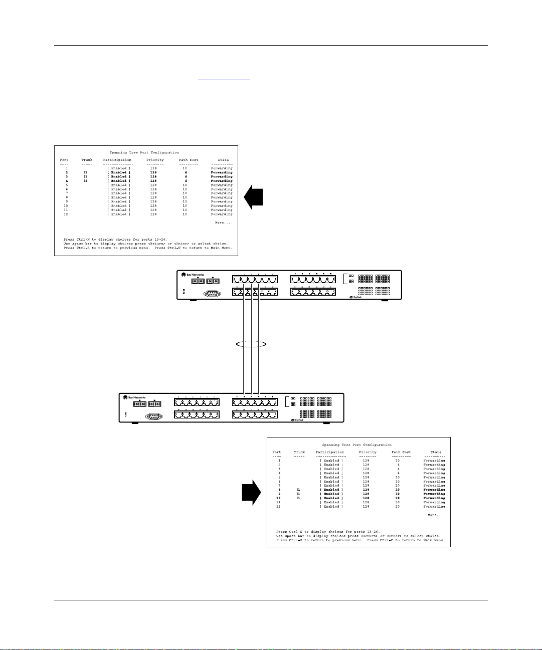
Getting Started
The switch can also detect trunk member ports that are physically misconfigured.
For example, in Figure 1-28
, trunk member ports 2, 3, and 4 of switch SW1 are
configured correctly to trunk member ports 8, 9, and 10 of switch SW2. The
Spanning Tree Port Configuration screen for each switch shows the port State
field for each port in the Forwarding state.
SW1 Port Configuration screen
789101112
26
25
SW1
123456
100
F Dx
Activity
Comm Port
Power
Diagnostics
13 14 15 16 17 18
350F-HD
19 20 21 22 23 24
10/100 Autosense Switch
100
10
F Dx
Activity
100
10
F Dx
Activity
I1
26
25
123456
100
F Dx
Activity
13 14 15 16 17 18
350F-HD
SW2
Comm Port
Power
Diagnostics
SW2 Port Configuration screen
Figure 1-28. Example 1: Correctly configured trunk
893-00992-E
789101112
19 20 21 22 23 24
10/100 Autosense Switch
100
10
F Dx
Activity
100
10
F Dx
Activity
BS0024B
1-43
Page 82

Using the BayStack 350 Series 10/100 Autosense Switch
If switch SW2’s trunk member port 10 is physically disconnected and then
reconnected to port 12, the Spanning Tree Port Configuration screen for switch
SW1 changes to show port 4 in the Blocking state (Figure 1-29
[Blocking]
SW1 Port Configuration screen
SW1
Comm Port
Power
Diagnostics
I1
).
789101112
26
25
123456
100
F Dx
Activity
13 14 15 16 17 18
350F-HD
19 20 21 22 23 24
10/100 Autosense Switch
100
10
F Dx
Activity
100
10
F Dx
Activity
789101112
26
25
123456
100
F Dx
SW2
Comm Port
Power
Diagnostics
Activity
13 14 15 16 17 18
350F-HD
19 20 21 22 23 24
10/100 Autosense Switch
SW2 Port Configuration screen
Figure 1-29. Example 2: Detecting a misconfigured port
1-44
100
10
F Dx
Activity
100
10
F Dx
Activity
BS0025A
893-00992-E
Page 83

Getting Started
Additional Tips About the MultiLink Trunking Feature
When you create a MultiLink Trunk, the individual trunk members (the specific
ports comprising the trunk) are logi cally connect ed and react as a si ngle entity. For
example, if you change spanning tree parameters for any trunk member, the
spanning tree parameters for all trunk members are changed.
All configured trunks are indicated in the Spanning Tree Configuration screen.
The screen’s Trunk field lists the active trunks, adjacent to the port numbers that
correspond to the specific trunk member for that trunk.
When a trunk is active you can di sable spann ing tre e part icip ation us ing t he Trunk
Configuration screen or using the Spanning Tree Configuration screen.
When a trunk is not active, the spanning tree participation setting in the Trunk
Configuration screen does not take effect until the Trunk Status field is set to
Enabled.
When MultiLink Trunking is active, all VLAN screens change to show only five
VLANs available for configuration. VLAN columns V6 to V8 are not displayed.
Also, if more than five VLANs are configured and you try to enable a MultiLink
trunk, the trunk configuration screen prompts you to reconfigure VLANs V6
through V8.
Port Mirroring (Conversation Steering)
You can designate one of your switch por ts to moni tor t raffic on an y two spe cif i ed
switch ports (port-based) or to monitor traffic to or from any two specified
addresses that the switch has learned (address-based).
A probe device, such as the Nortel Networks StackProbe or equivalent,
Note:
must be connected to the designated monitor port to use this feature (contact
your Nortel Networks sales agent for details about the StackProbe).
893-00992-E
1-45
Page 84

Using the BayStack 350 Series 10/100 Autosense Switch
The following sections provide example configurations for both monitoring
modes available with the Port Mirroring feature:
• Port-based Mirroring
• Address-b ased Mirroring
A sample of the Port Mirroring Configuration screen is provided with each of the
examples to support the network configuration example.
Note that in the following examples, the displayed screens do not show all of the
screen prompts that precede some actions. For example, when you configure a
switch for port mirroring or when you modify an existing port mirroring
configuration, the new configuration does not take effect until you respond [Yes]
to the following screen prompt:
Is your port mirroring configurat ion complete? [ Yes ]
1-46
For more information about the Port Mirroring feature, see “Port Mirroring
Configuration” on page 3-48.
Port-Based Mirroring Configuration
Figure 1-30
shows an e xa mple of a port -base d mirror ing con f i gurat ion where por t
12 is designated as the monito r por t fo r por ts 24 and 25 of switch SW1. Although
this example shows ports 24 and 25 monitored by the monitor port (port 12), any
of the trunk members of I1 and I2 can also be monitored.
Trunks cannot be monitored and trunk members cannot be configured
Note:
as monitor ports (see “MultiLink Trunking Configuration Rules
page 1-41
Figure 1-31
).
shows the Port Mirror ing Configuration screen set up for th is e xampl e.
” on
893-00992-E
Page 85

Getting Started
StackProbe
Monitor port
(port 12)
SW2
Port X
(port 25)
SW1
F
Comm Port
Power
Diagnostics
I1
F
123456
26
25
789101112
13 14 15 16 17 18
Comm Port
350F-HD
19 20 21 22 23 24
10/100 Autosense Switch
100
10
F Dx
Activity
100
10
F Dx
Activity
100
F Dx
Comm Port
Power
Diagnostics
SW3
Activity
Power
Diagnostics
123456
26
25
789101112
13 14 15 16 17 18
350F-HD
19 20 21 22 23 24
10/100 Autosense Switch
100
10
F Dx
Activity
100
10
F Dx
Activity
100
F Dx
Activity
Port Y
(port 24)
I2
123456
26
25
789101112
13 14 15 16 17 18
350F-HD
19 20 21 22 23 24
10/100 Autosense Switch
100
10
F Dx
Activity
100
10
F Dx
Activity
BS0026A
100
F Dx
Activity
893-00992-E
Figure 1-30. Port-based mirroring configuration example
In this configuration example, the designated monitor port (port 12) can be set to
monitor traffic in any of the following modes:
• Monitor all traffic received by port X
• Monitor all traffic transmitted by port X
• Monitor all traffic received and transmitted by port X
• Monitor all traffic received by port X or transmitted by port Y
• Monitor all traf fic recei ved b y por t X (des tined t o port Y) a nd then tr ansmitte d
by port Y
• Monitor all traffic received/transm itted by port X or received/transm itted by
port Y (or all conversations between port X and port Y)
1-47
Page 86

Using the BayStack 350 Series 10/100 Autosense Switch
As shown in the Port Mirroring Configuration screen example (Figure 1-31), a
user has designated port 1 2 as t he Monit or Port for ports 24 and 2 5 in swi tch SW1.
The Monitoring Mode field [ - > Port X or Port Y - > ] indicates that all traffic
receiv ed b y port X or all traffic transmitted by port Y is currently being monitored
by the StackProbe attached to Monitor Port 12.
The screen data displayed at the bottom of the screen shows the currently active
port mirroring configuration.
Port Mirroring Configuration
Monitoring Mode: [ -> Port X or Port Y -> ]
Monitor Port: [ 12 ]
Port X: [ 25 ]
Port Y: [ 24 ]
Address A: [ 00-00-00-00-00-00 ]
Address B: [ 00-00-00-00-00-00 ]
Port mirroring configuration has taken effect.
Currently Active Port Mirroring Configuration
--------------------------------------------Monitoring Mode: -> Port X or Port Y -> Monitor Port: 12
Port X: 25 Port Y: 24
Use space bar to display choices, press <Return> or <Enter> to select choice.
Press Ctrl-R to return to previous menu. Press Ctrl-C to return to Main Menu.
Figure 1-31. Port Mirroring port-based screen example
See “Port Mirroring Con figuration” on page 3-48 for a full descrip ti on o f t he Port
Mirroring Configuration screen fields.
1-48
893-00992-E
Page 87

Getting Started
Address-Based Mirroring Configuration
Figure 1-32
shows an e xample o f an a ddress -based mirro ring c onf ig urati on where
port 12, the designated monitor port for switch SW1, is monitoring traffic
occurring between address A and address B.
Address A
StackProbe
Monitor port
(port 12)
123456
26
25
789101112
13 14 15 16 17 18
123456
13 14 15 16 17 18
350F-HD
350F-HD
19 20 21 22 23 24
10/100 Autosense Switch
789101112
19 20 21 22 23 24
10/100 Autosense Switch
100
10
F Dx
Activity
100
10
F Dx
Activity
100
10
F Dx
Activity
100
10
F Dx
Activity
SW2
100
F Dx
Comm Port
Power
Diagnostics
SW1
F
I1
Activity
F
123456
26
25
789101112
13 14 15 16 17 18
Comm Port
350F-HD
19 20 21 22 23 24
10/100 Autosense Switch
100
10
F Dx
Activity
100
10
F Dx
Activity
I2
26
25
100
F Dx
Activity
100
F Dx
Comm Port
Power
Diagnostics
SW3
Activity
Power
Diagnostics
893-00992-E
Address B
BS0027A
Figure 1-32. Address-based mirroring configuration example
In this configuration, the designated monitor port (port 12) can be set to monitor
traffic in any of the following modes:
• Monitor all traffic transmitted from address A to any address
• Monitor all traffic received by address A from any address
• Monitor all traffic received by or transmitted by address A
• Monitor all traffic transmitted by address A to address B
• Monitor all traffic between address A and address B (conversation between
the two statio ns)
1-49
Page 88

Using the BayStack 350 Series 10/100 Autosense Switch
Figure 1-33 shows the Port Mirroring Configuration screen setup for this
example.
In this example, port 12 becomes the designated Monitor Port for switch SW1
when you press [Enter] in response to the [Yes] screen prompt. The screen data
displayed at the bottom of the screen changes to show the new currently active
port mirroring configuration.
The Monitoring Mode field [ Address A - > Address B ] indicates that all
traff i c transmitted by address A to addr es s B wil l be monitored by the StackProb e
attached to Monitor Port 12.
Note:
When you enter MAC addresses in this screen, they are also displayed
in the MAC Address Table screen (see “MAC Address Table” on page 3-24).
Port Mirroring Configuration
Monitoring Mode: [ Address A -> Address B ]
Monitor Port: [ 12 ]
Port X: [ ]
Port Y: [ ]
Address A: [ 00-44-55-44-55-22 ]
Address B: [ 00-33-44-33-22-44 ]
Is your Port mirroring configuration complete? [ Yes ]
Currently Active Port Mirroring Configuration
--------------------------------------------Monitoring Mode: Address A <-> Address B Monitor Port: 1
Address A: 00-11-22-33-44-55 Address B: 22-33-44-55-66-77
Use space bar to display choices, press <Return> or <Enter> to select choice.
Press Ctrl-R to return to previous menu. Press Ctrl-C to return to Main Menu.
Figure 1-33. Port Mirroring address-based screen example
See “Port Mirroring Con figuration” on page 3-48 for a full descrip ti on o f t he Port
Mirroring Configuration screen fields.
1-50
893-00992-E
Page 89

Getting Started
Port Mirroring Configuration Rules
The following configuration rules must be applied to any port mirroring
configuration:
1.
A monitor port cannot be configured as a trunk member.
2.
When a port is configured and enabled as a monitor port, the port is
automatically disabled from participating in the spanning tree. When the port
is reconfigured as a standard switch port (no longer a monitor port), the port
becomes enabled for spanning tree participation.
3.
When creating a port-based port mirroring configuration, be sure that the
monitor port and both o f t he mirrored ports, port X and port Y, are configured
on the same VLAN. Use the VLAN Configuration screen to configure the
VLAN (see “VLAN Configuration” on page 3-34).
4.
VLAN configuration settings for any ports configured for port-based
mirroring cannot be changed. Use the Port Mirroring Configuration screen to
disable port mirroring (or reconfigure the port mirroring ports), then change
the VLAN configuration settings. See also Step 3.
Quick-Start Procedures
This section provides Quick-Start procedures for installing and setting up the
BayStack 350 switch. It is intended for experienced network installers or system
administrators who are familiar with the BayStack 350 switch installation and
setup procedures in this manual.
If you hav e e xperi enc e inst alli ng netw or k de vi ces, or i f you are ins tall ing mu ltipl e
BayStack 350 switches, you can use the installation flowchart provided in this
section to guide you through the installation. If you need more information about
any of the steps in the flowchart, see Chapter 2, “Installing the BayStack 350
Switch” for a complete explanation of the installation process.
After you have verified the installation, you can use other Quick-Start procedures
in this section to set up and begin managing the switch. For detailed information
about setting up the switch and using the console interface (CI) menus and
screens, see Chapter 3, “Using the Console Interface.”
893-00992-E
1-51
Page 90

Using the BayStack 350 Series 10/100 Autosense Switch
Quick-Start to Installing the BayStack 350 Switch
You can use the installation flowchart (Figure 1-34) to install the BayStack 350
switch. If you need more information about any of the steps in the flowchart, see
the appropriate section in Chapter 2, “Installing the BayStack 350 Switch.”
Start
Check contents of
shipping package
Check site preparation
requirements
Mounting
switch on table
or shelf?
Yes
Secure
switch to mounting
surface?
Yes
Install mounting brackets
Install on table
or shelf
A
No
No
Figure 1 -34. Install ation flowchart
Mounting switch
on wall?
Yes
Install on wall Install in rack
No
A
Connect port cables
Connect power
Verify the installation
Configure the switch
for management
1-52
893-00992-E
Page 91

Quick-Start to Managing the BayStack 350 Switch
If you are already familiar with managing network devices, you can use the
Quick-Start procedur es i n t his se ction to set up and begin managin g the BayStack
350 switch. Before you begin these procedures, make sure that the BayStack 350
switch has been installed and verified (as described in Chapter 2, “Installing the
BayStack 350 Switch”), and that the network cables are attached to the switch.
This section describes how to manage the BayStack 350 switch using one of two
methods:
• The console/service port interface, using the CI menus and screens
• An SNMP management application
Console/Service Port Interface
If you are managing the BayStack 350 switch using the console/service port
interface, follow these steps:
1.
Connect a console terminal directly to the BayStack 350 switch console/
service port or through a modem connection.
Getting Started
893-00992-E
Note:
The console/service port is configured as a data communications
equipment (DCE) connector. Ensure that your RS-232 cable pinouts are
configured for DCE connections ( see “DB-9 (RS-232- D) Console/Serv ice Port
Connector” on page C-5).
The console terminal can be a VT100-compatible terminal or a PC running
VT100 terminal-emulation software (see “Console/Service Port Cabling”
on page 3-2).
2.
Configure the console terminal for 9600 baud, 8 data bits, no parity, and
1 stop bit.
Be sure to set the console terminal to online mode; do not leave it in setup
mode.
3.
Press [Ctrl]+C on the console terminal keyboard.
4.
The CI main menu opens.
For more information about the CI main menu, see “Using the CI Menus and
Screens” on page 3-4.
1-53
Page 92

Using the BayStack 350 Series 10/100 Autosense Switch
SNMP Management Applications
T o use an SNMP ap plication t o manage the Ba yStack 350 s witch, you must assign
an IP address to t he sw itch so that the S NMP a pplic ati on can communicat e wi th it .
To assign the BayStack 350 switch IP address, follow these steps:
1.
Connect a console terminal directly to the BayStack 350 switch
console/service port or through a modem connection.
The console/service port is configured as a data communications
Note:
equipment (DCE) connector. Ensure that your RS-232 cable pinouts are
configured for DCE connections ( see “DB-9 (RS-232- D) Console/Serv ice Port
Connector” on page C-5).
The console terminal can be a VT100-compatible terminal or a PC running
VT100 terminal-emulation software (see “Console/Service Port Cabling”
on page 3-2).
2.
Configure the console terminal for 9600 baud, 8 data bits, no parity, and
1 stop bit.
1-54
Be sure to set the console terminal to online mode; do not leave it in setup
mode.
3.
Press [Ctrl]+C on the console terminal keyboard.
4.
The CI main menu opens.
For more information about the CI main menu, see “Using the CI Menus and
Screens” on page 3-4.
5.
Choose the IP Configuration option from th e main menu.
The IP Configuration screen opens.
6.
In the IP Configuration screen, complete the following fields:
-- In-Band IP Address
-- In-Band Subnet Mask (if required)
-- Default Gateway (if required)
7.
Set SNMP traps (if required).
To set SNMP traps, see “SNMP Configuration” on page 3-14.
8.
Press [Ctrl]+C to return to the main menu.
893-00992-E
Page 93

Chapter 2
Installing the BayStack 350 Switch
This chapter explains how to install the BayStack 350 switch. The switch can be
placed on a table or shelf, mounted on a wall, or installed in a standard 19-inch
equipment rack.
To install the BayStack 350 switch, you unpack the equipment, physically install
the switch, connect the network cables, connect the power, and then verify the
installation.
Required Tools and Materials
You will need the following tools to install the BayStack 350 switch:
• For installation in an equipment rack, use a Phillips or crosshead screwdriver.
• For wall mounting, you need four screws (not supplied). The screw size and
type depends on the composi tion of the wa ll on whi ch you i ntend to mount the
switch. Have an experienced maintenance person choose the appropriate
hardware for your wall composition.
Caution:
weight of the devi ce, plus the addit ional weight of the atta ched net work cables
and power cords.
The screws and wall composition must be able to withstand the
893-00992-E
2-1
Page 94

Using the BayStack 350 Series 10/100 Autosense Switch
Pac ka ge Contents
Verify that your BayStack 350 switch shipment inc lu des all of the ite ms shown in
Figure 2-1
AC
power cord
Installation
hardware:
Mounting
brackets
and screws
.
25
26
123456
Power
Diagnostics
Comm Port
13
14
78910
15
16
17
18
19
20
21
Documentation:
11
12
25
26
100
123456
F Dx
22
7
8
23
Activity
9
10
11
24
12
100
1314 1516 17 18
10
F Dx
19
20
21
Activity
22
23
24
100
10
350F-HD
F Dx
10/100 Autosense Switch
Activity
BayStack 350 10/100 Autosense
Switch (Model 350F-HD, Model 350F,
Model 350T-HD, or Model 350T)
Rubber
footpads
Figure 2-1. Package contents
If any items are missing or damaged, contact the sales agent or the customer
service representative from whom you purchased the BayStack 350 switch.
2-2
Using the BayStack 350 Series
10/100 Autosense Switch
Owner registration card
Customer registration card
Release notes
7829FB
893-00992-E
Page 95

Site Preparation
This section describes what you need to do to prepare your site before installing
the BayStack 350 switch.
Hardware
Verify that you have the hardware components appropriate for your method of
installation:
• Console terminal: You must have a console terminal available. The console
terminal must be a VT100-compatible terminal or a PC running VT100
terminal-emulation software. (Although the BayStack 350 switch is
operational as soon as you install it, you can customize the parameters to suit
your needs.)
• Rack mounting: You need a single-unit (1u) rack space for installing the
Model 350T and the Model 350F switches in an equipment rack. The Model
350T-HD and the Model 350F-HD switches require a 1.5-unit (1.5u) rack
space.
Installing the BayStack 350 Switc h
893-00992-E
• Surface mounting:
-- Table: The table or shelf must be level and able to support at least
12 pounds, plus the weight of the suspended port cables. If you intend to
stack additional Ba ySta ck 350 switches, remember to i ncl ude t his we igh t in
your calculations when selecting a suitable table or shelf.
Caution:
tabletop, the accumulated weight of the port cables increases with the
height of the shelf or tabletop.
-- Wall-mounting hardware: Mounting brackets are provid ed for securing the
BayStack 350 switch (Model 350F and Model 350T only) on a table, shelf,
or wall. However, because wall compositions vary at different sites, Nortel
Networks recommends that an experienced maintenance person choose the
appropriate wall-mounting hardware to install your BayStack 350 switch
properly.
• Network cabling: Ensure that all network cables are in place and that they
have been tested and tagged before you begin the installation.
When this device is installed in a stack on a shelf or
2-3
Page 96

Using the BayStack 350 Series 10/100 Autosense Switch
Software
Verify that you have the software components appropriate for your method of
installation:
• BootP server: The BayStack 350 switch can learn its IP address through
BootP. To use this feature, ensure that you have a properly configured BootP
server in your network.
• TFTP server: You can keep your BayStack 350 switch firmware up-to-date
by upgrading the firmware as new versions become available. To upgrade the
firmware, you need a properly configured TFTP server in your network.
The Nortel Networks network management applications EZ LAN
Optivity Campus
™
, and Optivity Enterprise™ can help you with these BootP and
firmware functions.
Environment
The follo w ing i tems must conform to the s pecifications descr ib ed in Appendix A,
“Technical Specifications”:
™
,
2-4
• Temperature: Ensure that the temperature in the operating environment
remains between 0
and 40°C (32o and 104oF). Do not place the BayStack 350
°
switch in direct sunlight or near warm air exhausts or heaters.
• Humidity: Ensure that the humidity level in the operating environment does
not exceed 85 per ce nt and t hat no w at er cond enses o n or a round t he BayS tack
350 switch.
• Ventilation: Ensure t hat there is a dequate airflow and clearance for air
circulation around the BayStack 350 swi tch. Air enter s the swit ch on one side
and flows ou t t he o pposite side. Allow at lea st two inches of ventilati on s pac e
on both sides of the BayStack 350 switch.
• Electrical power: Ensure that the site’s power outlet meets the power
requirement of the BayStack 350 switch and is within 1.8 meters (6 feet) of
the installation locatio n.
893-00992-E
Page 97

Installation
Installing the BayStack 350 Switc h
This section explains how to install, power up, and verify the operation of the
BayStack 350 switch. Before you begin these procedures, read and follow the
instructions in “
Site Preparation” on page 2-3.
Warning:
connect the power cord until instructed to do so.
You can install the BayStack 350 switch in any of the following locations:
• Surface mounting:
-- Table or shelf (secured or unsecured)
-- Wall (Model 350F and Model 350T only)
• Rack mounting:
-- Standard equipment rack
Surface Mounting
You can mount the BayStack 350 swit ch on an y surf ace t hat can sa fely suppo rt th e
weight of the switch and att ached cables, as long as there is adeq uate space around
the unit for ventilation and access to cable connectors. You can use the mounting
brackets supplied wit h the swit ch (Model 350F and Model 350 T only) to secur e it
to the installation locat ion.
Note:
table or shelf. However, if conditions warrant securing the switch (for
example, in locations wh ere the switch might accidentally fall from a shelf or
overhead location), you can secure the switch using two mounting brackets
(Model 350F and Model 350T only).
To avoid bodily injury from hazardous electrical current, do not
In most cases, it is not necess ary to s ecu re the Bay Stack 35 0 switch to a
893-00992-E
2-5
Page 98

Using the BayStack 350 Series 10/100 Autosense Switch
Attaching the Mounting Brackets
Figure 2-2
shows the mountin g-brack et positions for mounting t he Model 350F or
Model 350T switch on a flat surface such as a table, shelf, or wall. When rack
mounting the swit ch, you use the same brackets, but position them to a tt ac h t o t he
holes in the chassis (Figure 2-5
).
To attach the mounting brackets for a surface mount, follow these steps:
1.
Locate the rack-mounting holes on each side of the switch (Figure 2-2).
2.
Using a Phillips or crosshead screwdriver, attach a mounting bracket to
each side of the switch using the supplied screws.
3.
Secure the switch to the table, shelf, or wall as described in the
appropriate section.
350T
10/100 Autosense Switch
585FB
2-6
Figure 2-2. Attaching mounting brackets for a surface mount
893-00992-E
Page 99

Installing the BayStack 350 Switc h
Installing on a Table or Shelf
To install the BayStack 350 switch on a table or shelf, follow these steps:
1.
Attach a rubber footpad to each corner on the bottom of the switch
(Figure 2-3
2.
Position the swit ch on the table or shelf, with the front panel facing you.
).
Be sure to lea v e adequate spac e aro und the unit f or v entil ation and acce ss
to the cables .
3.
If you are securing the switch to a table or shelf, insert two screws (not
supplied) through each of the mounti ng brack ets, the n tighten th e scr ews.
4.
Proceed to “Connecting Port Cables” on page 2-13 to co nnect the
network cables.
893-00992-E
310T
586FA
Figure 2-3. Attaching rubber footpads
2-7
Page 100

Using the BayStack 350 Series 10/100 Autosense Switch
Wall Mounting
You can mount the Model 350F and Model 350T on any wall that can safely
support the weight of the device and attached cables (see “
page 2-3
optional.
Note:
Before You Begin
Before mounting the switch on a wall, note the following considerations:
• Mount the switch on the wall, with the front panel facing up, as shown in
• Position the switch at a height that allows the LEDs to be visible at all times.
• Do not let the attached port cables hang freely from the port connectors.
for safety conside rations). F or a wal l mount, use of the r ubber footp ads is
You cannot mount the Model 350F-HD on a wall.
Figure 2-4
.
Install plastic cable clamps to support and arrange the cables.
Site Preparation” on
2-8
• Choose the appropriate mounting hardware for your wall composition.
(Wall-mounting screws are not supplied.)
• Optionally, attach the switch to a piece of plywood (at least 0.5 in. thick) that
is firmly secured to the wall, preferably to the wall studs.
893-00992-E
 Loading...