

Page 1

Part No. 206380-A
September 1999
4401 Great America Park way
Santa Clara, CA 95054
Installation and Reference for
the BayStack 22 PC Card
Adapter
Page 2

Copyright © 1999 Nortel Networks
All rights reserved. September 1999.
The information in this document is subject to change without notice. The statements, configurations, technical data,
and recommendations in this document are believed to be accurate and reliable, but are presented without express or
implied warranty. Users must take full responsibility for their applications of any products specified in this document.
The information in this document is proprietary to Nortel Networks NA Inc.
Trademarks
NORTEL NETWORKS is a trademark of Nortel Networks.
Bay Networks is a registered trademark and BayStack and the Nortel Networks logo are trademarks of Nortel
Networks.
Microsoft, Windows, and Windows NT are registered trademarks of Microsoft Corporation.
All other trademarks and registered trademarks are the property of their respective owners.
Notice
Note: This equipment has been tested and found to comply with the limits for a Class A digital device, pursuant to
Part15 of the FCC rules. These limits are designed to provide reasonable protection against harmful interference
when the equipment is operated in a commercial environment. This equipment generates, uses, and can radiate radio
frequency energy. If it is not installed and used in accordance with the instruction manual, it may cause harmful
interference to radio communications. Operation of this equipment in a residential area is likely to cause harmful
interference, in which case users will be required to take whatever measures may be necessary to correct the
interference at their own expense.
EN 55 022 Statement
This is to certify that the Nortel Networks BayStack 22 PC Card Ad apter is shielded against the generation of radio
interference in accordance with the application of Council Directive 89/336/EEC, Article 4a. Conformity is declared
by the application of EN 55 022 Class A (CISPR 22).
Warning: This is a Class A product. In a domestic environment, this product may cause radio interference, in which
case, the user may be required to take appropriate measures.
EC Declaration of Conformity
This product conforms to the provisions of Council Directive 89/336/EEC and 73/23/EEC. The Declaration of
Conformity is available on the Nortel Networks World Wide Web site at http://libra2.corpwest.baynetworks.com/
cgi-bin/ndCGI.exe/DocView/.
ii
206380-A
Page 3

Voluntary Control Council for Interference (VCCI) Statement
Voluntary Control Council for Interference (VCCI) Statement
This is a Class A product based on the standard of the Voluntary Control Council for Interference by Information
Technology Equipmen t (V CCI). If this equipment is used in a dom estic environm ent, radio disturbance may ari se.
When such trouble occurs, the user may be required to take corrective actions.
Canadian Department of Communications Radio Interference
Regulations
This digi tal apparatus (BayStack 22 PC Card Adapter) does not exceed the Class A limi ts for radio-noise emissions
from digital apparatus as set out in the Radio Interference Regulations of the Canadian Depar tm ent of
Communica tions.
Règlement sur le brouillage radioélectrique du ministère des
Communications
Cet appareil numér ique (BaySt ack 22 PC Card Adapter) respecte le s limites de bruits radioélectriques visant le s
appareils numériques de classe A prescrites dans le Règlement sur le brouillage radioélectrique du ministère des
Communications du Canada.
Electrom agnetic Interference (EMI) State ment
206380-A
iii
Page 4

Wichtige Sicherheit shin wei se
1. Bitte les en Sie diese Hinweise sorgfaltig durch.
2. Heben Sie diese Anleitung fur den spateren Gebrauch auf.
3. Vor jedem Reinigen ist das Gerat vom Stromnetz zu trennen. Verwenden Sie keine Flu ssigoder A erosolreiniger.
Am besten eignet sich ein angefeuchtetes Tuch zur Reinigung.
4. Um eine Beschadigung des G erates zu vermeiden sollten Sie nur Zubehorteile verwenden, die vom Hersteller
zugelassen sind.
5. D a s G e ra t ist vor Feuch tigkeit zu schut ze n .
6. Bei der Aufstellung de s G erates ist auf sicheren Stand zu achten. Ein Kippen oder F allen konnte Verletzu ngen
hervorrufen. Verw enden Sie nur sichere Standorte und beachten Sie die Aufste llhinweise des Herstellers.
7. Die Beluftungsoffnungen dienen der Luftzirkulation die das Gerat vor Uberhitzung schutzt. Sorgen Sie dafur,
daB diese Offnungen nicht abgedeckt wer d en.
8. Beachten Si e beim AnschluB an das Stromnetz die AnschluBwerte.
9. Die Netzanschlusteckdose muB aus Grunden der elektrischen Sicherheit einen Schutzleiterkontakt haben.
10. Verlegen Sie die Netzan schluBleitung s o, daB n iemand da ruber fallen kann. Es sollte auch nichts auf der Leitung
abgestellt werden.
11. Alle Hinweise und Warnungen, die sich am Gera ten befinden sind zu beachten.
12. Wird das Gerat uber einen langeren Zeitraum nicht benutzt, sollten Sie es vo m Stromne tztrennen. Somit wird im
Falle ei ner Uberspannung eine Beschadigung vermieden.
13. Durch die Luftungsoffnungen durfen niem als Gege nstande od er Flussigkeiten in das Gerat gelangen. Dies
konnte einen Brand bzw. elektrischen Sch lag auslosen.
14. Offnen sie niemals das Gerat. Das Gerat darf aus Grunden der elektrischen Sicherheit nur von authorisiertem
Servicepersonal geoffnet werden.
15. Wenn folgende Situationen au ftreten ist das Gera t vom Stromnetz zu trennen und v on einer qualifizierten
Servicestelle zu uberprufen:
a. Netzkabel oder Netzstecker sind beschadigt.
b. Flussigkeit ist in das Ge rat eingedrungen.
c. Das Gerat war Fe uchtigkeit ausgesetzt.
d. Wenn das Ge rat nicht der Bedienungsanleitung entsprechend funktioniert oder Sie mit Hilfedieser Anleitung
keine Verbesserung erzielen.
e. Das Gerat ist gefallen und/oder das G e hause is t beschadi gt.
f. Wenn das Gerat deutliche An zeichen eines Defekt es aufweist.
16. Bei Reparat uren durfen nur Orgi nalersatzteile bzw. den Orginalteilen entsprechende Teile verw endet werde n .
Der Einsat z von ungeeigneten Ersatzteilen kann eine weitere Beschadigung hervorrufen.
17. Wenden Sie sich mit allen Fragen die Service und Repartur betreffen an Ihren Servicepartner. Somit stellen Si e
die Betriebssicherheit des Gerates sicher.
18. Zum Netzan schluB dieses Gerates ist eine geprufte Leitung zu verw enden. Fur einen Nennst rom bis 6A und
einem Gerategew icht groBer 3kg ist eine Leitun g nicht leichter als H05VV-F, 3G, 0.75mm 2 einzusetzen.
Der arbeit splatzbezogene Schalldruckpegel nach D IN 45 635 Teil 1000 betragt 70dB(A) oder weniger.
iv
206380-A
Page 5

Restricted Rights Legend
Use, duplication, or disclosure by the United States Government is subject to restrictions as set forth in subparagraph
(c)(1)(ii) of th e Rights in Technical Data and Comput er Softwa re clause at DFARS 252.227-7013.
Notwithstandi ng any other license ag reement that may per tain to, or accompany the delivery of, this computer
software, the rights of the Unite d States Governm ent reg arding its use, reproduction, and disclosure are as set forth in
the Commer cial Computer Software-Restricted Rights clause at FAR 52.22 7-19.
Statement of Conditions
In the intere st of improving internal design, oper ational function, and/o r relia bility, Nortel Networks NA Inc. reserves
the right to make ch anges to the products de scribed in this document without notice .
Nortel Networks NA Inc. doe s not assume an y liability that may occur due to the use or application of the product(s)
or circui t layout(s) described herein.
Portions of the code in this software product are Copyright © 1988, Regents of the Uni versity of California. All rights
reserved. Redistribu tion and use in source and binary forms of such portions are permitted, provided that the above
copyrig ht notic e an d th is para grap h ar e dup lica te d in al l such f or ms and th at a n y docum en tati on, adv e rtis in g mat er ials ,
and other materials related to such distribution and use acknowledge that such portions of the software were
developed by the University of California, Berkeley. The name of the University may not be used to endorse or
promote products derived from such portions of the softw are wit hout speci fic prior writte n permissi on.
SUCH PORTI ONS OF THE SOFTWARE ARE PROVIDED “AS IS” AND WITHOUT ANY EXPRESS OR
IMPLIED WARRANTIES, INCLUDING, WITHOUT LIMITATION, THE IMPLIED WARRANTIES OF
MERCHANTABILITY AND FITNESS FOR A PARTICULAR PURPOSE.
Nortel Networks NA Inc. Software License Agreement
NOTICE: Pl ease carefully read this license agreement before copying or using the accom panying software or
installing the hardwa re unit w ith pre-enabled s oftware (each of which i s referred to as “Software” in this Agreement).
BY COPYING OR USING THE SOFTWARE, YOU ACCEPT ALL OF THE TERMS AND CONDITIONS OF
THIS LICENSE AGREEME N T. THE TERMS EXPRESSED IN THIS AGREEMENT ARE THE ONLY TERMS
UNDER WHICH NORTEL NETW ORKS WI LL PERM IT YOU TO USE THE SOFTWARE. If you do not accept
these terms and conditions, return the product, unused and in the original shipping conta iner, within 30 days of
purchase to obtain a cr edit for the full purchase price.
1. License Grant. Nortel Networks NA Inc. (“Nortel Networks”) grants the end user of the Softw are (“Lic ensee”) a
personal , none xcl us iv e , non trans fe ra ble li cen se: a) t o use th e Sof tware eit he r on a singl e compu te r or , if appli ca bl e, on
a single authorized device identified by host ID, for which it was originally acquired; b) to copy the Software solely
for backup purpose s in support of authorized use of th e Software; and c) to use and copy the associated user manual
solely in support of authorized use of the Software by License e. This license applies to the Soft w are on ly and does not
extend to Nortel Networks Agent softwa re or other Nortel Networks software products. Nortel Netwo rk s Agent
software or other N ortel Net w orks software products are l icensed for use under the terms of the applicable Nortel
Networks NA Inc. Software License A greement that accompanies such software and upon payment by the end user of
the applicable license fees for such software.
2. Restri ctions on use; reservation of rights. The Software and user manuals are protected under copyright laws.
Nortel Networks and/or its licensors retain all title and ownersh ip in both the Software and user manuals, including
any revisions made by Nortel Networks or its li censors. The copyright notice m ust be reproduced and included with
any copy of an y por tion of the Soft war e or user man uals. Lic ens ee may not modi fy, translate , dec ompi le, di sa ssem ble,
use for any competitive analysis, reverse engineer, distribute, or create derivative works from the Software or user
manuals or any copy, in whole o r in part. Ex cept as e xpressly provided in this Agreement, L icensee may not copy or
transfer the Software or user manuals, in whole or in part. Th e Softwar e and user manuals embody No rtel Networks’
206380-A
v
Page 6

and its licensors’ confidential and propri etary intellectual property. Licensee shall not subli cense, a ssign, or other w ise
disclos e to any third party the Software, or any information about the operation, design, performance, or
implementation of the Software and user manuals that is confidential to Nortel Networks and its licensors; however,
Licensee may grant permission t o its consultants, subcontractors, and agent s to use the Software at Licensee’s facility,
provided they have ag reed to use the Software only in accordanc e w ith the te rm s of this license.
3. Limited warranty. Nortel N etworks warrants each item of Software, as delivered by Nortel Networks an d properly
installed and operated on Nortel Networks hard w are or other equipment it is ori g inally licensed for, to function
substant ially as described in its accom panying u ser manual dur ing its warranty period, whic h begins on the date
Softwar e is fir st shippe d to Li censee . I f an y item of Soft wa re f ail s to so functi on duri ng its warr an ty peri od, as th e sole
remedy Nor tel Net wor ks wil l at it s discr et ion provi de a sui tabl e f ix, pat ch , or wo rkaro und fo r the prob lem th at may be
included in a future Software release. Nortel Networks further warra nts to Lice nsee that the media on which the
Software is provided will be free from def ects in m aterials and workmanship under normal use for a period of 90 days
from the date Softw a re is first shipped to Licensee. Nortel N e tworks w ill replace defective media at no charge if it is
returned to Norte l N etworks during the warran ty period along with pro o f of the date of shipment. This warranty do es
not apply i f the media has been damaged as a result of accident, misuse, or abuse. The Licensee assumes all
resp on s i b il ity for sele ction of th e S of tw ar e to achieve Li ce nsee’s inten de d results and for th e instal la ti on, use, an d
result s obtained from the Softw are. Nortel Networks does not warrant a) that the functions contained in t he software
will meet the Licensee’s requirements, b) that the Software will operate in the hardware or software combinations that
the Licensee may select, c) that the operation of the Softw are will be uninterrupted or error free, or d) that all defects
in the operation of the Softw are will be corrected. Nortel Networks is not oblig ated to re m edy any Soft w are defect
that canno t be reprod uce d wit h the lates t Soft war e re le ase. Th ese war ran ties do not apply to the So ft war e if it has been
(i) alt ered, except by Nortel Networks or in ac cordance wi th its instructions; (ii) used in conjunction with another
vendor’s product, r esulting in the defect; or (iii ) dam aged by i mp roper environment, abu se, misuse , accident, or
negligence. THE FOREGOING WARRANTIES AND LIMITATIONS ARE EXCLUSIVE REMEDIES AND ARE
IN LIEU OF ALL OTHER WARRANTIES EXPRESS OR IMPLIED, INCLUDING WITHOUT LIMITATION
ANY WARRANTY OF MERCHANTABILITY OR FITNESS FOR A PARTICULAR PURPOSE. Licensee is
responsible for the secur ity of its own data and information and fo r m aintain ing adequat e procedures apart from the
Software to reconstruct lost or altered files, data, or pr ograms.
4. Limitation of liability. IN NO EVENT WILL NORTEL NETWORKS OR ITS LICENSORS BE LIABLE FOR
ANY COST OF SUBSTITUTE PR OCUREMENT; SPECIAL, INDIRECT, INCIDENTAL, OR CONSEQUENTIAL
DAMAGES; OR ANY DAMAGES RESULTING FROM INACCURATE OR LOST DATA OR LOSS OF USE OR
PROFITS ARISI NG OUT OF OR IN CONNECTION WITH THE PERFORMANCE OF THE SOFTWARE, EVEN
IF NOR TEL NETWORKS HAS BEEN ADVISED OF THE POSSIBILITY OF SUCH DAMAGES. IN NO EVENT
SHALL THE LIABILITY OF NORTEL NETWORKS RELATING TO THE SOFTWARE OR THIS AGREEMENT
EXCEED THE PRICE PAID TO NORTEL NETWORKS FOR THE SOFTWARE LICENSE.
5. Gove rn m e nt Lice n se es. This provision applies to all Software and documentat ion acquired directly or indirectly
by or on behalf of the United States Government. The Software and documentation are commercial products, licensed
on the open market at ma rket prices, and were deve loped entirely at private expense and without the use of an y U.S.
Gove rnment funds. The license to the U.S. Governme nt is granted only with restricted rights, and use, duplication, or
disclosure by the U.S. Governmen t is subject to the res trictions set fo rth in subparagraph (c)(1) of th e Com mercial
Computer Software––Restricted Rights clause of FAR 52.227-19 a nd the limitations set out in this license for civilian
agencies, and subparagraph (c)(1)(ii) of the Rights in Technical Data and Computer Software clause of DFARS
252.227-7013, for agencies of the Departm ent of Defense or their successors, whichever is applicable.
6. Use of Software in the Europe an Community. T hi s pr ov ision applies to al l So f t ware acquired for use with in the
European Comm unity. If Licensee uses the Software within a country in the Europea n Com m unity, the Software
Directive enacted by the Council of European Communities Directive dated 14 May, 1991, will apply to the
examination of the Software to facilitate interoperability. Licensee agrees to notify Nortel Networks of any such
intended exami nation of the Software and may procur e support and assistance from Nort el Networks.
vi
206380-A
Page 7

7. Term and termination. This license is effective until terminat ed; however, all of the restrictions with respect to
Nortel Networ ks’ copy right in the Softwar e and user manuals will cease being effective at the date of expiration of the
Nortel Networks copyright; those restrictions relating to use and disclosure of Nortel Networks’ confidential
information sha ll continue in effect. Licensee may terminat e this license at any time. The license will automat ically
terminate if Licensee fails to comply with any of the terms and conditions of the license. Upon termination for any
reason, Licensee w ill immediately destroy or return to No rtel Networks the Software, user manuals, and all copies.
Nortel Networks is not liabl e to Licens ee for damages in any form solely by reason of the termination of this license.
8. Export and Re-export. Licensee agrees not to export, directly o r indirec tly, the Software or related t echnical data
or information without first obtaining any required export licenses or other governmental approvals. Without limiting
the foregoing , Licensee, on behalf of itself and its subsidiaries and affiliates , agrees that it will not, without first
obtaini ng all expo rt licenses and approvals required by the U.S. G overnment: (i) export, re-export, transf er, or divert
any such Software or technical data, or any direct product thereof, to any country to which suc h exports or re-exports
are restricted or embargoed under Uni ted States export control laws and regulations, or to any national or resident of
such restricted or embar goed countr ies; or (ii) provide the Software or relate d technical data or information to any
militar y end user or for any mili tary end us e, including the design, development , or production of any chemical,
nuclear, or biological w eapons.
9. General. If any provision of this Agreement is held to be invalid or unenforceable by a court of competent
jurisdiction, the remainder of the provisions of this Agreement shall remain in full force and effect. This Agreement
will be governed by the law s of the state of Califor nia.
Should you have any questions concerning this Agr eement, co ntact Nortel Networks, 4401 Great America Parkway,
P.O. Box 58185, Santa Clara, California 95054-8185.
LICENSEE ACKNOWLEDGES THAT LICENSEE HAS READ THIS AGREEMENT, UNDERSTANDS IT, AND
AGREES TO BE BOUND BY ITS TERMS AND CONDITIONS. LICENSEE FURTHER AGREES THAT THIS
AGREEMENT IS THE ENTIRE AND EXCLUSIVE AGREEMENT BETWEEN NORTEL NETWORKS AND
LICENSEE, WHICH SUPERSEDES ALL PRIOR ORAL AND WRITTEN AGREEMENTS AND
COMMUNICATIONS BETWEEN THE PARTIES PERTAINING TO THE SUBJECT MATTER OF THIS
AGREEMENT. NO DIFFERENT OR ADDITIONAL TERMS WILL BE ENFORCEABLE AGAINST NORTEL
NETWORKS UNLESS NORTEL NETWORKS GIVES ITS EXPRESS WRITTEN CONSENT, INCLUDING AN
EXPRESS WAIVER OF THE TERMS OF THIS AGREEMENT.
206380-A
vii
Page 8

viii
206380-A
Page 9

Contents
Preface
Before You Begin ............................................................................................................. xv
Text Co n ventions ...................... ....... ..................... ....... ....... ...................... ....... ....... .........xv
Technical Publications .....................................................................................................xvi
How to Get Help ..............................................................................................................xvi
Chapter 1
Introduction
BayStack 22 PC Card Adapter Overview .......................................................................1-1
Product Features ............................................................................................................1-1
Product Description ........................................................................................................1-2
BaySta ck 22 Network Card ......................................................................................1-2
68-Pin Connector ...............................................................................................1-2
15-Pin Connector ...............................................................................................1-3
Media Coupler ...................................................................................................1-3
System Requir e men ts .................... ....... ....... ..................... ....... ....... ...................... ...1-5
Operating Environments .......................................................................................... 1-6
Cabl e Requi re me n ts ..... ..................... ............... ....... ....... ..................... ....... ....... ......1-6
Fast Ethernet Cables (100 Mb/s) ....................................................................... 1-6
Ethernet Cables (10 Mb/s) .................................................................................1-6
Typical Ap plications ....................... ....... ....... ..................... ....... ....... ...................... ....... ...1-7
Chapter 2
Hardware I nstallation
Package Contents ..........................................................................................................2-1
Installing the BayStack 22 PC Card Adapter ..................................................................2-2
Removing the BayStack 22 PC Card Adapter ................................................................2-3
206380-A
ix
Page 10

Chapter 3
Software Installation
Preinstallation ................................................................................................................. 3-2
Installing the Network Driver in a Windows 95 Environment ..........................................3-2
Configuring the Windows 95 Environment ...................................... ....... ..... ....... ......3-6
Installing the Network Driver in a Windows 98 Environment ........................................ 3 -11
Configuring the Windows 98 Environment ...................................... ....... ..... ....... ....3-18
Configuring the Interrupt Request ..........................................................................3-21
Installing the Network Driver in a Windows NT 4.0 Environment .................................3-23
Configuring the Windows NT Environment ........................................................ ....3-27
Installing the Network Driver in a Novell NetWare 4.x Environment .............................3-32
Installing the Network Card in a Novell NetWare Server ........................................3-32
Specifying Driver Pa rameters ..........................................................................3-35
Installing the Network Card in a Novell NetWare Client .........................................3 -36
Chapter 4
Troubleshooting
Diagnostic LEDs .............................................................................................................4-1
Hardware Issues ......... .............. .............. ....... ..................... ............... ....... ....... ...............4-2
Software Issues ..............................................................................................................4-2
Appendix A
Technical Specifications
Product Specifications ...................................................................................................A-1
Software Drivers ............................................................................................................A-2
Appendix B
Novell NetWare Reference Information
Novell NetWare Server Files ..........................................................................................B-1
File Descrip tions .............................. .............. ....... ...................... .............. ....... .......B-1
Sample AUTOEXEC.NCF Files ...............................................................................B-2
AUTO.EXEC.NCF Fil e Parameters .......... .............. ............... ....... ....... .............. B-2
Novell NetWare Client Files ...........................................................................................B-4
Client Files ..............................................................................................................B-4
NET.CFG Files and Parameters . .............................................................................B -5
Sample NET.CFG File ......................................................................................B-5
NET.CFG File Parameters ................................................................................ B-5
Index
x
206380-A
Page 11

Figures
Figure 1-1. BayStack 22 Network Card Connectors ................................. ..... ..... .. ..... .1-2
Figure 1-2. Media Coupler ..........................................................................................1-3
Figure 1-3. LEDs ........................................................................................................1-4
Figure 1-4. BayStack 22 Network Card Installation .................................................... 1-7
Figure 1-5. Typical Application ...................................................................................1-8
Figure 2-1. BayStack 22 Network Card Installation .................................................... 2-2
Figure 3 -1. New Hardware Found Window—Generic ................................................3-2
Figure 3 -2. New Hardware Found Window—BayStack 22 Network Card . .................3-3
Figure 3-3. Update Device Driver Wizard Dialog Box ................................................ 3-3
Figure 3-4. Copying Files Dialog Box .........................................................................3-4
Fi gure 3-5. Upda te Devi ce Driver Wizard Dialog Box—Ba ySt ack 22 Net work Card ..3-4
Figure 3-6. System Settings Change Dialog Box .......................................................3-5
Figure 3-7. Network Dialog Box—Configuration Tab ..................................................3-6
Figure 3-8. Proper t ies Dialog Box ..............................................................................3-7
Figure 3-9. Resources Dialog Box .............................................................................3-8
Figure 3-10. Select Network Component Type Dialog Box ..........................................3-9
Figure 3-11. Select Network Protocol Dialog Box ........................................................3-9
Figure 3 -12. TCP /IP Properties Dialog Box ...............................................................3-10
Figure 3-13. New Hardware Found Window—Generic ..............................................3-11
Figure 3-14. New Hardware Found Window—BayStack 22 Network Card ................ 3 -12
Figure 3-15. Add New Hardware Wizard Dialog Box .................................................3-12
Figure 3-16. Add New Hardware Wizard—Driver Selection Dialog Box ....................3 -13
Figure 3-17. Add New Hardware Wizard—Driver Location Dialog Box ......................3-14
Figure 3-18. Add New Hardware Wizard—Driver Search Dialog Box ........................3-15
Figure 3-19. Inser t Disk Message ..............................................................................3-15
Figure 3-20. Copying Files Dialog Box .......................................................................3-16
Figure 3-21. Add New Hardware Wizard—Installation Finished Dialog Box ..............3-17
206380-A
xi
Page 12

Figure 3-22. System Settings Change Dialog Box .....................................................3-17
Figure 3-23. Network Dialog Box—Configuration Tab ................................................3-18
Figure 3-24. BayStack 22 Network Driver Dialog Box—Advanced Tab ......................3-19
Figure 3-25. Access Control Tab ................................................................................3-20
Figure 3-26. Resources Tab .......................................................................................3-21
Figure 3-27. Edit Interrupt Request Dialog Box ..........................................................3-22
Figure 3-28. Network Dialog Box—Adapters Tab .......................................................3-23
Figure 3-29. Select Network Adapter Dialog Box ....................................................... 3-24
Figure 3-30. Insert Disk Dialog Box ...........................................................................3 -24
Figure 3-31. Select OEM Option Dialog Box ..............................................................3-25
Figure 3 -32. W indows NT Configuration Dialog Box ..................................................3 -26
Figure 3-33. Bindings Tab ..........................................................................................3-27
Figure 3-34. Bindings Tab—All Adapters Selection ....................................................3 -28
Figure 3-35. IP Address Tab .......................................................................................3-29
Figure 3-36. DNS Tab .................................................................................................3 -30
Figure 3-37. WINS Address Tab .................................................................................3-31
xii
206380-A
Page 13

Tables
Table 1-1. LED Indications ........................................................................................1-5
Table 4-1. LED Indications ........................................................................................4-1
Table A-1. Technical Spe c i fications ................. ...................... ....... ....... .....................A-1
Table A-2. Available Software Drivers ......................................................................A-2
Table B-1. Server Files .............................................................................................B-1
Table B -2. Server Connection Type Parameters ......................................................B -4
Table B-3. Client Fil e s ........... ....... ...................... ....... ..................... .............. ....... .....B-4
Table B -4. Client Connection Type Parameters ........................................................ B-6
206380-A
xiii
Page 14

xiv
206380-A
Page 15

Congratulations on your purchase of a BayStack™ 22 PC Card Adapter, which
supports 10 Mb/s and/or 100 Mb/s transmission speeds. This network card is
intended for use in laptop computers. You can use a similar product, the
BayStack 21 PCI 10/100 Adapter w/WOL, in a desktop workstation or server.
Before You Begin
Preface
This guide provides information about using the features and capabilities of the
BayStack 22 PC Card Adapter.
This guide is intended for Ethernet local area network (LAN) administrators with
the following background:
• Working knowledge of PC terminology and operation
• Working knowledge of 10BASE-T (Ethernet) and 100BASE-TX
(Fast Ethernet) operations
• Nortel Networks
Text Conventions
This guide uses the following text conventions:
bold text
™
network experience
Indicates command names and options and text that
you need to enter.
Example: Enter
a:\
.
separator ( > ) Shows menu paths.
206380-A
Example: From the Windows taskbar, choose Start >
Settings > Control Panel.
xv
Page 16

Installation and Reference for the BayStack 22 PC Card Adapter
Technical Pub lication s
You can print selected technical manuals and release notes free, dir ectly from the
Internet. Go to support.baynetworks.com/libr ary/tpubs/. Find the product for
which you need documentation. The n locate the specific category and model or
version f or your hardware or software produc t. Using Adobe Acrobat Rea der , you
can open the manuals and release notes, search for the sections you need, and pr int
them on most standard printers. You can download Acrobat Reader free from the
Adobe Systems Web site, www.adobe.com.
How to Get Help
If you purchas e d a serv ice co n tract for your Nortel Networks product from a
distributor or authorized reseller, contact the technical support staff for that
distributor or reseller for assistance.
If you pur c hased a Nort el Networks service progra m, contact one of the following
Nortel Networks Technical Solu tions Centers:
Technical Solutions Center Telephone Number
Billerica, MA 800-2LANWAN (800-252-6926)
Santa Clara, CA 800-2LANWAN (800-252-6926)
Valbonne, France 33-4-92-96-69-68
Sydney, Australia 61-2-9927-8800
Tokyo, Japan 81-3-5402-7041
#
206380-A
Page 17

Chapter 1
Introduction
This chapter provides an overview of the BayStack 22 PC Card Adapter,
including its hardware and sof tware components. The BayStack 22 PC Card
Adopter complements the BayStack 70-Series 10/100 Ethernet Switches and
BayStack 60-Series 10/100 Ether net Hubs.
Note:
Card Adopter in this doc ument, may a lso be referred to as a PCMCIA Ethernet
Adapter.
The BayStack 22 PC Card Adapter, also known as the BayStack 22 PC
BayStack 22 PC Card Adapter Overview
The BayStack 22 PC Card Adapter provides network connectivity to laptop
computers. You install the network card into your computer to access network
resources such as servers, printers, and the Inte rnet or intranet . You can install the
BayStack 22 PC Card Adopter on many operating systems, such as Microsoft®
Windows® 95, Windows 98, and Windows NT® or Nove ll NetWare.
Product Features
The BayStack 22 PC Card Adopter provides the followin g feat ures:
• Plug-and-play installation for Windows 95 and Windows 98
• 10/100 Mb/s autonegotiati on with half- and full-duplex support
• 20/200 Mb/s full-duplex suppo rt
206380-A
1-1
Page 18
Installation and Reference for the BayStack 22 PC Card Adapter
Product Description
The BayStack 22 PC Card Adapter is a standard-size PCMCIA card. A media
coupler provides network access to your laptop computer.
BayStack 22 Network Card
The BayStack 22 PC Card Adapter includes the following components:
• 68-pin connector
• 15-pin connector
• Media coupler , inc luding:
— 10 megabits per second (Mb/s) and 100 Mb/s Link LEDs
— Activity LED
— 15-slot connector
— RJ-45 port
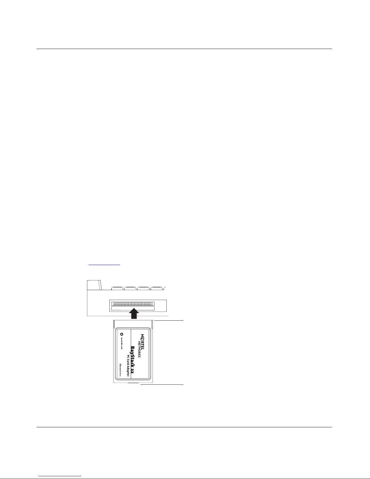
68-Pin Connector
The standard 68-pin connector on one end of the BayStack 22 PC Card Adopter
(Figure 1-1
) plugs into the Type II or Type III slot on your computer.
68-pin connector
15-pin connector
9493EA
Figure 1-1. BayStack 22 Network Card Connectors
1-2
206380-A
Page 19
Introduction
15-Pin Connector
The standard 15-pin connector on the other end of the BayStack 22 PC Card
Adopter (Figure 1-1
) attaches to the 15-slot connector on the media coupler.
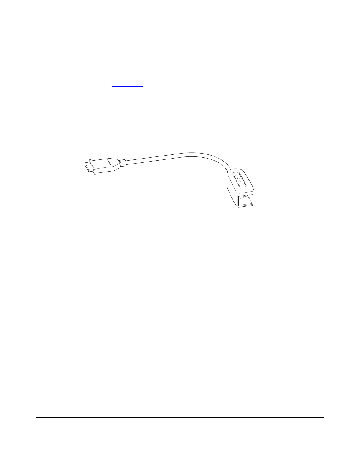
Media Coupler
The media coupler (Figure 1-2
) provides connection to the BayStack 22 PC Card
Adopter and to Ethernet networ k devices. Three LEDs located on the media
coupler indicate 10 Mb/s or 100 Mb/s transmission speed and connection stability.
9476FA
Figure 1-2. Media Coupler
The 15-slot connector on the media coupler attaches to the 15-pin connect or on
the BayStack 22 PC Card Ado pter. The ot her end of the media coupl er c ontai ns an
RJ-45 port. You can attach a standard Ethernet cable to the RJ-45 port to connect
the network card to a network device such as a hub or switch.
RJ-45 Ethernet Por t
The RJ-45 10BAS E-T/100BASE- TX Etherne t port adapts to the correct network
speed of 10 Mb/s or 100 M b/s thro ugh autone goti at ion with the board c omponen ts
of the network card. The port is wir ed as an MDI-X port to connect to other
devi ces without using a crossover cable.
206380-A
1-3
Page 20
Installation and Reference for the BayStack 22 PC Card Adapter
9478FA
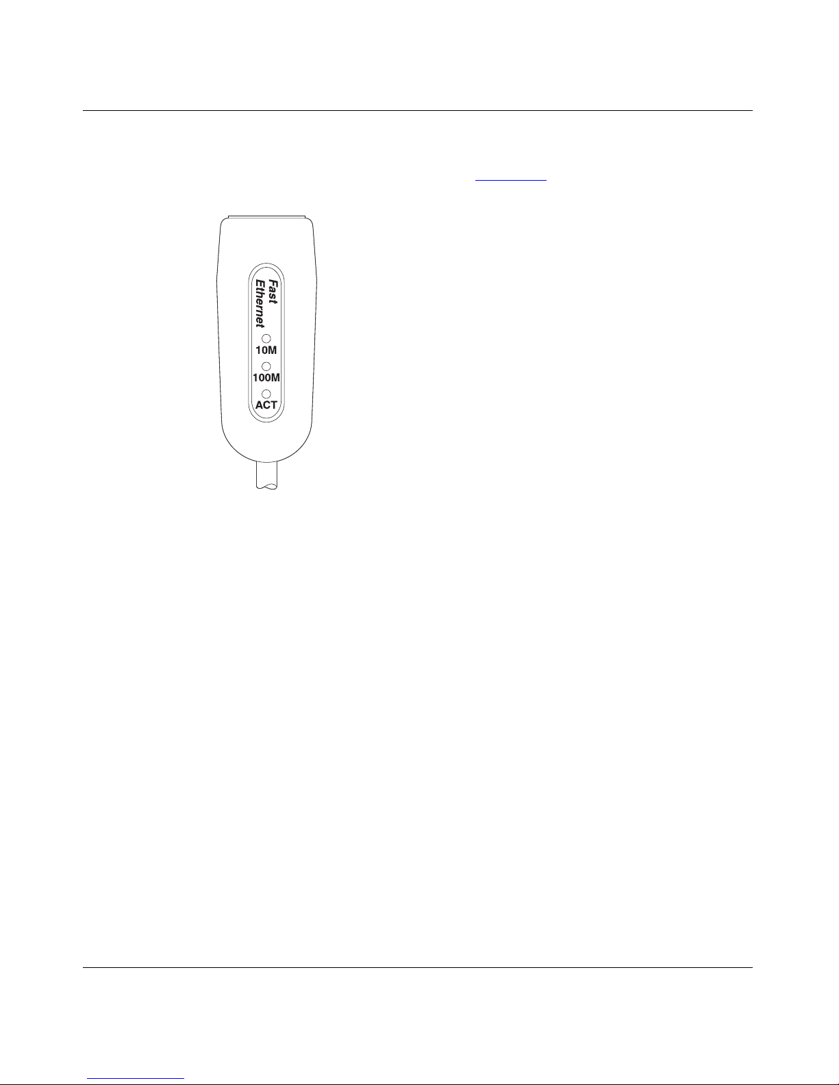
LEDs
The media coupler contains three LEDs (Figure 1-3).
Figure 1-3. LEDs
The 10 Mb/s and 100 Mb/s Li nk LEDs ind icate succ essf ul netwo rk connec tions to
Ethernet and Fast Ethernet devices, respectively. The Link LEDs remain steady if
the connection is stable. You should check the RJ-45 con nection if the LED is not
steady. The Activity LED indicates that network traffic is passing through the
port.
1-4
206380-A
Page 21

Table 1-1 describes the Link and Activity LED indications.
Tabl e 1 -1 . LED Indic at io ns
Label Color Activity Description
10M Green On A 10 Mb/s connection has been established.
Off Power is not supplied to the netw ork card, or a 10 Mb/s
connection is not established.
100M Green On A 100 Mb/s connection has been established.
Off Power is not supplied to a network card, or a 100 Mb/s
connection is not established.
ACT Green On Heavy network traffic is passi ng through the port.
Green Blinking Network traffic is passing through the connected port.
The rate of blinking is proportional to the amount of
netw o rk traff ic.
Introduction
System Requirements
Laptop computers using the BayStack 22 PC Card Adopter must meet the
follo wing r equirements:
• A laptop computer that is IBM compatible and includes:
— A 386SX or faster processor
— At least one Type II PC Card socke t
— Card Services and Socket Services compliant with PCMCIA Release 2.1
• Microsoft W indows 95, Windows 98, or Windo ws NT, including an operati ng
system as described in “
• 100BASE-TX Fast Ethe rne t or 10BAS E-T Ethernet c onnect ivi ty to your local
area network (LAN)
Operating Environments.”
206380-A
1-5
Page 22

Installation and Reference for the BayStack 22 PC Card Adapter
Operating Environments
The BayStack 22 PC Card Adopter supports the following operating systems:
• Microsoft Windows NT 3.51, 4.0
• Microsoft Wind ows 95, Windows 98
• Microsoft LAN Manager 2.x
• Microsoft Wind ows for Workgroups 3.11
• Microsoft Windows 3.1
• Novell NetWare 3.x, 4.x
• Lantastic 6.0
• IBM OS/2 W arp Version 3
Cable Requirements
You can use Category 5 (Cat 5) Ethernet cables for 10 Mb/s and 100 Mb/s
network connections to the BayStack 22 PC Card Adopter.
Use the following guidelines when using Cat 5 cables:
• Maximum length between a workstation and a hub is 100 meters (m).
• Maximum length between two hubs is 10 m.
• Maximum length between two hubs that are functioning as Ethernet Class 2
repeaters is 100 m.
• Maximum total length between two workst at ions is 205 m.
Fast Ether ne t C ab l es (100 Mb/s )
You must use a Cat 5 st raight -thr ough cable wit h one RJ- 45 conne ctor on eac h end
for 100 Mb/s Ethernet connections. Do not use a crossover cable.
Ethernet Cables (10 Mb/s)
You can use Cat 3, Cat 4, or Cat 5 unshielded twisted pair (UTP) cable or an
EIA/TIA-568 100-ohm shielde d twisted pair (STP) cable for 10 Mb/s Ethernet
connections . You must use a straight-through cable with an RJ-45 connector on
each end. Do not use a crossov er cable.
1-6
206380-A
Page 23
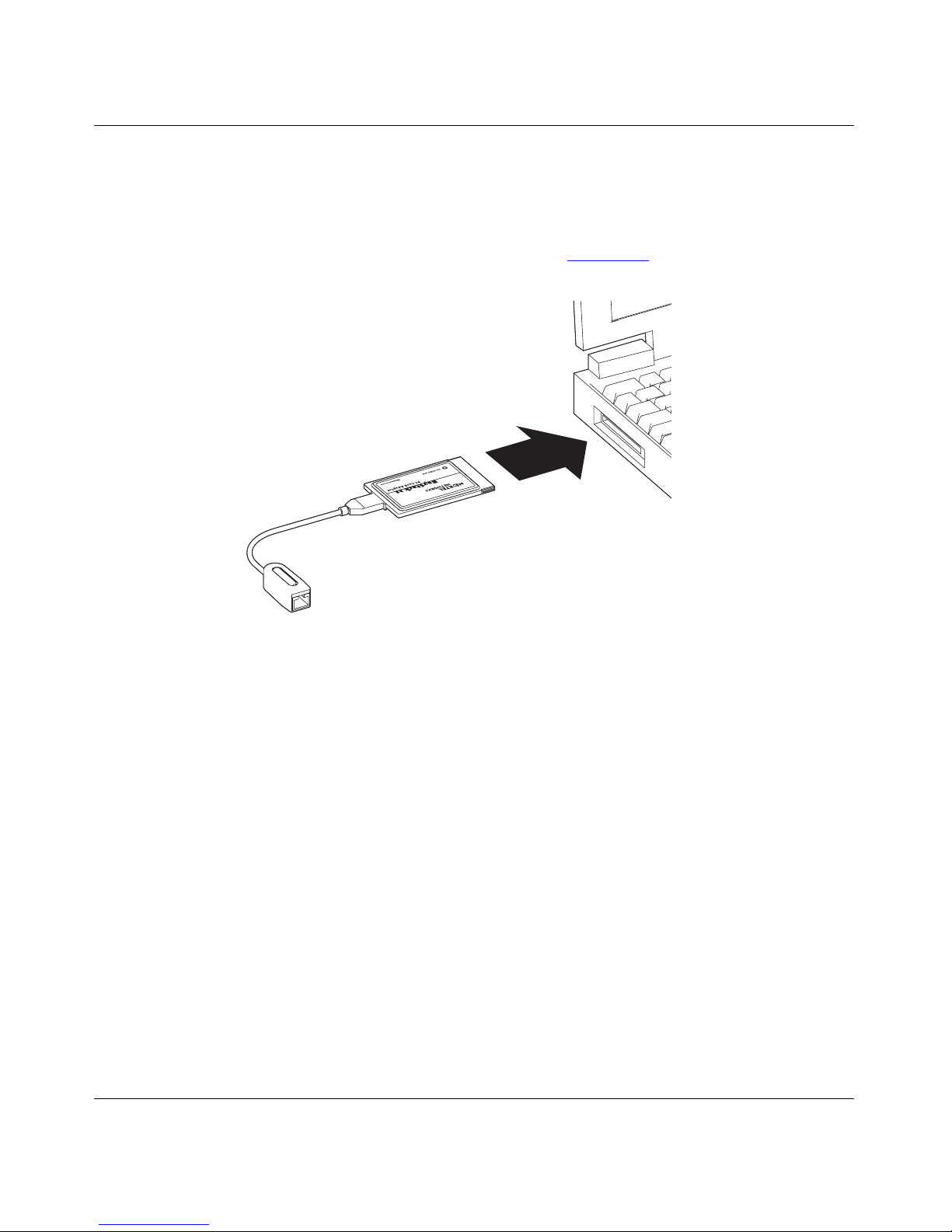
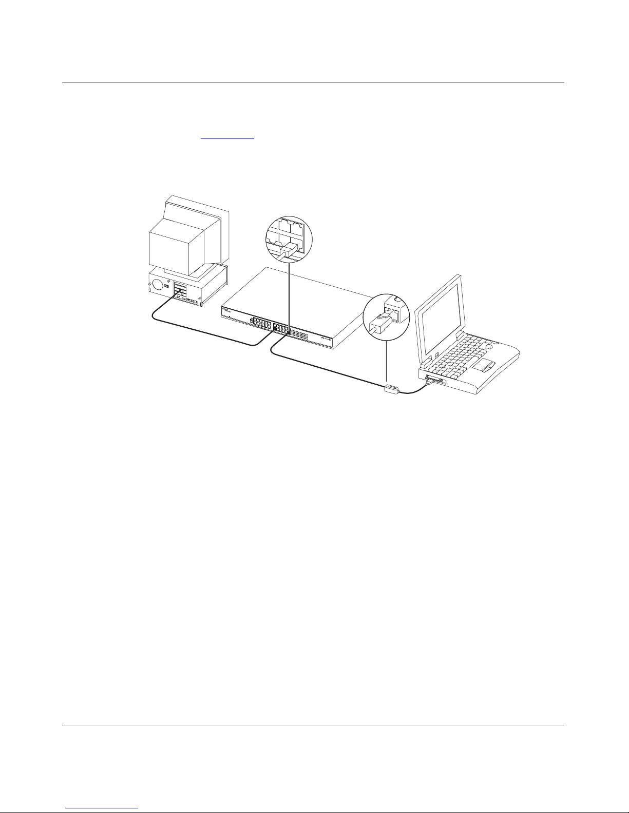
Typical Applicati ons
The BayStack 22 PC Card Adopter provides you with network connectivity to
your laptop computer. Attach the media coupler to the network card; then insert
the network card into your laptop computer (Figure 1-4).
Introduction
9477FA
Figure 1-4. BayStack 22 Network Card Installation
206380-A
1-7
Page 24
Installation and Reference for the BayStack 22 PC Card Adapter
Use standard Ethernet cables to connect network devices, such as hubs, to the
media coupler. You can then attach other devices to the hub to share netw or k
resources. Figure 1-5
provides an example of a laptop computer attached to a
BayStack 60-24T 10/100 Ethernet Hub. You can attach the hub to other
workstations, printers, servers, and additiona l laptop computers.
Figure 1-5. Typical Application
9479FA
1-8
206380-A
Page 25

Chapter 2
Hardware Installation
This chapte r describes ho w to install the components of t he BayStack 22 PC Card
Adapter in a portable (laptop) computer. Instructions f or connecting the installed
network card to the network are provided.
Note:
before installing the driv er .
You must connect all of the hardware, as described in this chapter,
Package Contents
The BayStack 22 network card package contains the following:
• BayStack 22 PC Card Adapter, including plastic protector case
• Media coupler , with c abl e
• BayStack 22 PCMCIA Card Adapter Software & Documentation CD,
including technical documentation in PDF format
• Safety card
• Warranty/Registration card
206380-A
2-1
Page 26

Installation and Reference for the BayStack 22 PC Card Adapter
Installing t he BayStack 22 PC Card Adapter
This section p rovi des inst ructi ons for ins tallin g the BaySta ck 22 ne twor k card i nto
a laptop computer. Computers vary in design; therefor e , instructions and
illustrations in this section may not exact ly match your computer. However, the
procedures will be similar .
To install the BayStack 22 networ k card in a computer:
Shut down the comp uter.
1.
Unplug the computer power cord from the power source.
2.
Depress both sides of the 15- slot connector of the media coupler.
3.
Connect the media coupler to the network card.
4.
Be sure the medi a cou pler co n nector clicks securel y into pla ce.
5.
Insert the BayStack 22 network card into an empty CardBus PC Card
6.
slot on the laptop. The BayStack 22 network card label must be facing up
(Figure 2-1
).
Figure 2-1. BayStack 22 Network Card Installation
Be sure the network card is firmly secured.
7.
2-2
9477FA
206380-A
Page 27

Hardware Installation
Connect the RJ-45 connector of a standard Ethernet cable to the RJ-45
8.
port on the media coupler.
Be sure to follow the cable guidelines described in “ Cable Requirements
page 1-6.
Connect the other end of the Ethernet cable to a network device, such as
9.
a hub or switch.
Attach a power cord to your laptop. Plug the cord into a power source.
10.
Turn on power to the laptop.
11.
Be sure any connected devices are receiving power.
12.
Removi ng t h e BayS t ack 22 PC C ard Adapt e r
You can easily remo ve the BayStack 22 network card from your laptop computer,
if needed. Before you remo ve the network card you must stop the PCMCIA Card
Service.
Warning:
before stopping the PCMCIA Card Service. Your laptop will freeze if you
remov e the net work card incorrectly.
Do not remove the BayStack 22 network card from your laptop
” on
206380-A
To remove the BayStack 22 network card:
From the Windows taskbar, choose Start > Settings > Control Panel.
1.
Double-click PC Car d (PCMCIA).
2.
Select “Nortel Networks BayStack 22 PCMCIA card.”
3.
Click Stop.
4.
An “It is ok to remove the PCMCIA card” message is displayed.
Firmly grasp the network card and remove it from the computer.
5.
Depress both sides of the 15- slot connector of the media coupler.
6.
Remove the media coupler from the network card.
7.
2-3
Page 28

Page 29

Chapter 3
Software Installation
This chapter provides instructions f or ins talling the BayStack 22 network driver
software and configuring the BayStack 22 PC Card Adapter on your netw ork.
Driv e rs compatible with several operating systems are lo cated on the BayStack 22
PCMCIA Card Adapter Software & Documentation CD. You can install specific
dri vers for Windows 95, Windo ws 98, W indows NT, Novell NetWare 4.x, or other
systems.
This guide provides instructions for installing the drivers for Windows 95,
Windows 98, Windows NT, and Novell NetWare 4.x. You can read the
RELEASE.txt file in the BayStack 22 PCMCIA Card Adapter Software &
Documentation CD for instructions to install drivers for other operating systems.
Different versions of Windows operating systems may ha ve diffe rent installation
screens th an those shown in these instructions. Your installation screens may
appear in a different order than those in this chapter. You will be prompted for the
same information , regardless of the Windows version.
The BayStack 22 network card is automa tically detected b y Windows 95 and
Windows 98. Follow the instructions during this automatic installation process.
You will be prompted to insert the BayStack 22 PCMCIA Card Adapter Software
& Documentation CD into your laptop computer during the installation.
The driver must be manually instal led for Windows NT.
Note:
PCMCIA Ethernet adapter or controller.
The BayStack 22 PC Card Adapter may also be referred to as a
206380-A
3-1
Page 30

Installation and Reference for the BayStack 22 PC Card Adapter
Select which driver you want to install for your new hardware:
Preinsta ll ation
Perform the following tasks prior to installing the BayStack 22 network driver:
• Install the BayStack 22 network card before installing the BayStack 22
network driver.
• Remove all other network cards from the laptop computer. If you have other
network cards or adapters installed in your computer, the driver instal lation
process will not execute. You do not need to uninstall other network dri ver
software before you run the installation.
• Be sure to have the Windows 95 or W indows 98 CD and the BayStack 22
network driver CD ready to use during the installation. You may be prompted
to install either CD. You may receive the “Insert Disk” and “Please insert the
disk labeled Windo ws.. .” messages. If you receive these messages, inser t the
appropriate C D, e nter the appro priate drive letter and CD name, and click OK
to continue the installation. For example, if drive D is your CD drive and you
insert the Windows 95 CD, enter d:\win95 when prompted.
Install in g t he Net work Driver i n a Wind ows 95 Environment
This section describes the steps required to install the driver software in a
Windows 95 en vironment.
To install the driv er:
Turn on the power to the computer, and start Windows 95.
1.
A generic New Hardware Found windo w opens (Figure 3-1
New Hardware Found
PCMCIA Ethernet PCMCIA Adapter
Figure 3-1. N ew Hardware Fo und Window—Generic
).
9561DA
3-2
206380-A
Page 31

Soft w a r e In stal latio n
A second New Hardwa re Foun d windo w opens, identifying your BaySta ck 22
PC Card Adap t er (Figure 3-2).
New Hardware Found
Nortel BAYSTACK 22 PCMCIA Ethernet
Select which driver you want to install for your new hardware:
9495DB
Figure 3-2. New Hardware Found Window—Bay Stack 22
Network Card
The Update Device Driver Wizard dialog box opens (Figure 3-3).
Figure 3-3. Update Device Driver Wizard Dialog Box
Inse r t th e
2.
CD into the CD drive as prompted
206380-A
BayStack 22 PCMCIA Card Adapter Sof tware & Documenta tion
.
3-3
Page 32

Installation and Reference for the BayStack 22 PC Card Adapter
Click Next.
3.
The Copying Files dialog box opens (Figure 3-4
Copying Files...
The file ndishlp.sys on Windows 95 CD-ROM
could not be found.
Insert Windows 95 CD-ROM into the drive
selected below, and click OK.
Copy files from:
D:\Win95
).
OK
Cancel
Skip File
Details...
8528DD
Figure 3-4. Copying Files Dialog Box
Insert the Win dows 9 5 CD as in di cated.
4.
The next Update Device Driver Wizard dialog box (Figure 3-5
) indicates
that the new BayStack 22 network card has been found and the driver is
automatically loaded.
3-4
Update Device Driver Wizard
Windows found the following updated driver for this
device:
Nortel Baystack 22 10/100 Mbps Fast Ethernet
PCMCIA Adapter
If you want to use this driver, click Finish. If this is not the
correct driver and you want to search for a different driver
manually, click Other Locations.
Location of Driver
Other Locations...
< Back
Finish Cancel
8527DD
Figure 3-5. Update Device Driver Wizard Dialog Box—BayStack 22
Network Card
206380-A
Page 33

Soft w a r e In stal latio n
Click Finish.
5.
Another Copying Files dialog box opens.
Click OK.
6.
The System Settings Change dialog box opens (Figure 3-6
Figure 3-6. System Settings Change Dialog Box
Remove all CDs from the CD drive.
7.
Click Yes.
8.
).
Restarting your system is necessary to enable your PC to finish setting up
your new hardware.
206380-A
3-5
Page 34

Installation and Reference for the BayStack 22 PC Card Adapter
Configuring the Windows 95 Environment
This section provides instructions for configuring the BayStack 22 network card
on the network after you have installed the BayStack 22 network driver on your
Windows 95 laptop computer.
To configure the network properties for your laptop:
From the Windows taskbar, choose Start > Settings > Control Panel.
1.
Double-click Network.
2.
The Network dialog box opens. The configuration tab is displayed by default
(Figure 3-7
).
Figure 3-7. Network Dialog Box—Configuration Tab
3-6
206380-A
Page 35

Soft w a r e In stal latio n
Select Prope rties .
3.
The Properties dia log box open s. The Advanced tab is displayed by de fault
(Figure 3-8
).
206380-A
Figure 3-8. Properties Dialog Box
In the Property list, select Connection Type.
4.
The AutoSense value is displayed by d efault.
In the Value list, select from the following connect ion speed types:
5.
• AutoSense (Use this setting if you want the RJ-45 por t on the media
coupler to use the fastest speed supported by the attached device.)
• 100BASE-TX for 100 Mb/s connections
• 100BASE-TX or 10BASE-T full-duplex mode, for 10 and 100 Mb/s
switch connections
• 10BASE-T twisted pair for 10 Mb/s connections
3-7
Page 36

Installation and Reference for the BayStack 22 PC Card Adapter
Click OK.
6.
The Properties Dialog Box opens again (Figur e 3-8
Click the Resources tab.
7.
The Resources dialog box opens (Figure 3-9
).
).
Figure 3-9. Resources Dialog Box
Enter the C onfigura tio n ty p e, interrupt (IR Q) num b er, and I/O addre ss
8.
range, or accept the default settings.
Click OK.
9.
Return to the Network Dialog Box > Configuration tab (Figure 3-7).
10.
Click Add.
11.
3-8
206380-A
Page 37

Soft w a r e In stal latio n
Select TCP/IP.
12.
The Select Network Component Type dialog box ( Figure 3-10
Figure 3-10. Select Network Component Type Dialog Box
Select Protocol.
13.
Click Add.
14.
The Select Network Protocol dialog box opens (Figure 3-11
) opens.
).
Figure 3-11. Select Network Protocol Dialog Box
In the Manufacturers list, select Micro soft.
15.
206380-A
3-9
Page 38

Installation and Reference for the BayStack 22 PC Card Adapter
In the Network Protocols list, select TCP/IP.
16.
Click OK.
17.
Return to the Con figura tio n ta b.
18.
Select Prope rties .
19.
The TCP/IP Properties dia log box ope ns (Figur e 3-12
).
Figure 3-12. TCP/IP Properties Dialog Box
Select the IP Address tab.
20.
If the computer has a static IP address, specify the IP address, subnet
21.
mask, and default gateway of you r computer.
You can also choose the “Obtain an IP address automatically” option if the
computer does not have a static IP address. If you choose this option your
IP address will be supplied by DHCP.
3-10
206380-A
Page 39
Soft w a r e In stal latio n
Use the Gateway or DNS Configurati on tabs to configure other
22.
parameters, as needed.
Click OK.
23.
The Copying Files dialog box is displayed.
In the “Copy files from:” field, enter the location of the requested files or
24.
CD.
Click OK.
25.
The system restart dialog box opens. Restarting your system is necessary to
enable your PC to finish setting up your new hardware.
Remove the CD from the CD drive.
26.
Click Yes.
27.
Your system restarts.
Install in g t he Net work Driver i n a Wind ows 98 Environment
This section describes the steps required to install the driver software in a
Windows 98 en vironment.
To install the network dri ver:
Turn on the power to the computer, and start Windows 98.
1.
The New Hardware Found window opens, identi fying a gene ric netw ork car d.
For instance, the window may list “PCMCIA Ethernet Adapt er, or PCMCIA
Ethernet Controller” (Figure 3-13
New Hardware Found
PCMCIA Ethernet PCMCIA Adapter
Select which driver you want to install for your new hardware:
Figure 3-13 . New Hardware Fo und Window —G e neric
).
9561DA
206380-A
3-11
Page 40

Installation and Reference for the BayStack 22 PC Card Adapter
Select which driver you want to install for your new hardware:
A second New Hardwa re Foun d windo w opens, identifying your BaySta ck 22
PC Card Adap t er (Figure 3-14).
New Hardware Found
Nortel BAYSTACK 22 PCMCIA Ethernet
Figure 3-14. New Hardware Found Window—Bay Stack 22
Network Card
The Add New Hardware Wizard dialog box o pen s (Figure 3-15).
9495DB
Figure 3-15. Add New Hardware Wizard Dialog Box
3-12
206380-A
Page 41

Soft w a r e In stal latio n
Click Next.
2.
The Add New Hardware Wizard—Driver Selection d ialog b ox op en s
(Figure 3-16
).
Figure 3-16. Add New Hardware Wizard—Driver Selection Dialog Box
206380-A
3-13
Page 42

Installation and Reference for the BayStack 22 PC Card Adapter
Click Next.
3.
The Add New Hardware Wizard—Driver Location dialog box opens
(Figure 3-17
).
Figure 3-17. Add New Hardware Wizard—Driver Location Dialog Box
Insert the
4.
BayStack 22 PCMCIA Card Adapter Sof tware & Documenta tion
CD into your CD drive.
Select CD -ROM drive.
5.
3-14
206380-A
Page 43

Soft w a r e In stal latio n
Click Next.
6.
The Add New Hardware Wizard—Driver Search dialog box opens
(Figure 3-18
).
Figure 3-18. Add New Hardware Wizard—Driver Search Dialog Box
Click Next.
7.
The Insert Disk message is displayed (Figure 3-19
Figure 3-19. Insert Disk Message
).
206380-A
3-15
Page 44

Installation and Reference for the BayStack 22 PC Card Adapter
Click OK.
8.
The Copying Files dialog box opens (Figure 3-20
Figure 3-20. Copying Files Dialog Box
Insert your Windows 98 CD into the CD drive of your laptop.
9.
Specify the lett er o f your CD drive and your Win dows 98 C D.
10.
For instance, if drive F is your CD drive, enter
).
F:\WIN98
.
3-16
206380-A
Page 45

Soft w a r e In stal latio n
Click OK.
11.
The Add New Hardware Wizard—Installation Finished dialog box opens
(Figure 3-21
).
Figure 3-21. Add New Hardware Wizard—Installation Finished Dialog
Box
Click Finish.
12.
The System Settings Change dialog box opens (Figure 3-22
Figure 3-22. System Settings Change Dialog Box
).
Restarting your system is necessary to enable your PC to finish setting up
your new hardware.
206380-A
3-17
Page 46

Installation and Reference for the BayStack 22 PC Card Adapter
Remove the CD from the CD drive.
13.
Click Yes.
14.
Your system restarts.
Configuring the Windows 98 Environment
You must configure your laptop c omputer on the network after installing the
BayStack 22 network driver on your Windows 98 laptop computer.
To configure the network properties for your laptop:
From the Windows taskbar, choose Start > Settings > Control Panel.
1.
Double-click Network.
2.
The Network dialog box opens. The TCP/IP network protocol for the
BayStack 22 network driver is already installed.
The configuration tab (Figur e 3-23
) is displayed by default.
Figure 3-23. Network Dialog Box—Configuration Tab
3-18
206380-A
Page 47

Soft w a r e In stal latio n
Select No rtel Ba y St a ck 22 10/100 Mbps Fast Ethernet Adapter.
3.
Click Prope rties .
4.
The BayStack 22 network driver dialog box ope ns (Figure 3-24
).
206380-A
Figure 3-24. BayStack 22 Network Driver Dialog Box—Advanced Tab
Select the Advanced tab.
5.
In the Property list, select Connection Type.
6.
In the Value list, select one of the following:
7.
• AutoSense—Select the default AutoSense setting if you want the port to
use the fastest speed supported by the attached device.
• 10BaseT (Twisted Pair)—Use this setting for 10 Mb/s Ethernet hubs .
• 100BaseTx—Use this setting for 100 Mb/s Ethernet hubs.
• 100BaseTx or 10BaseT full duplex—Use these settings for 100 M b/s and
10 M b/s Ethernet switches.
3-19
Page 48

Installation and Reference for the BayStack 22 PC Card Adapter
Click OK.
8.
Return to the Network dialog box (Figure 3-23).
9.
Select the Access Control tab (Figure 3-25).
10.
Figure 3-25. Access Control Tab
Select Share-level access control.
11.
Click OK.
12.
The system restart dialog box opens.
Remove all CDs from the CD drive.
13.
Click Yes.
14.
Your system restarts.
3-20
206380-A
Page 49

Configuring the Interrupt Request
You can configur e the Inter rupt Request (IRQ) parameters. Nortel Networks
recommends configuring the IRQ only if you are an expert at network or
PC confi guration.
To configure the IRQ:
From the Windows taskbar, choose Start > Settings > Control Panel.
1.
Double-click System.
2.
Select the Resources tab (Figure 3-26).
3.
Soft w a r e In stal latio n
Figure 3-26. Resources T ab
Clear the “Use automatic settings” box .
4.
In the Resource type list, select Interrupt Req ue st .
5.
206380-A
3-21
Page 50
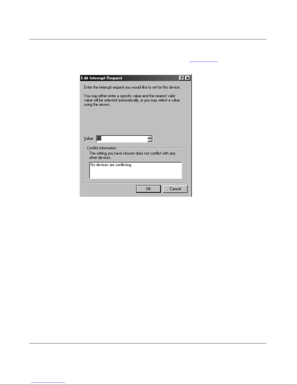
Installation and Reference for the BayStack 22 PC Card Adapter
Click Change Setting.
6.
The Edit Interrupt Request dialog box opens (Figure 3-27
).
Figure 3-27. Edit Interrupt Request Dialog Box
Use the arrows next to the Value field to select an IRQ value.
7.
Click OK.
8.
The Resources tab is displayed again. The new IRQ setting is displayed also.
Click OK.
9.
The “Create a Forced Configuration” message is displayed.
Click Yes.
10.
Insert the Windows 98 CD into the CD drive of you r laptop.
11.
3-22
206380-A
Page 51
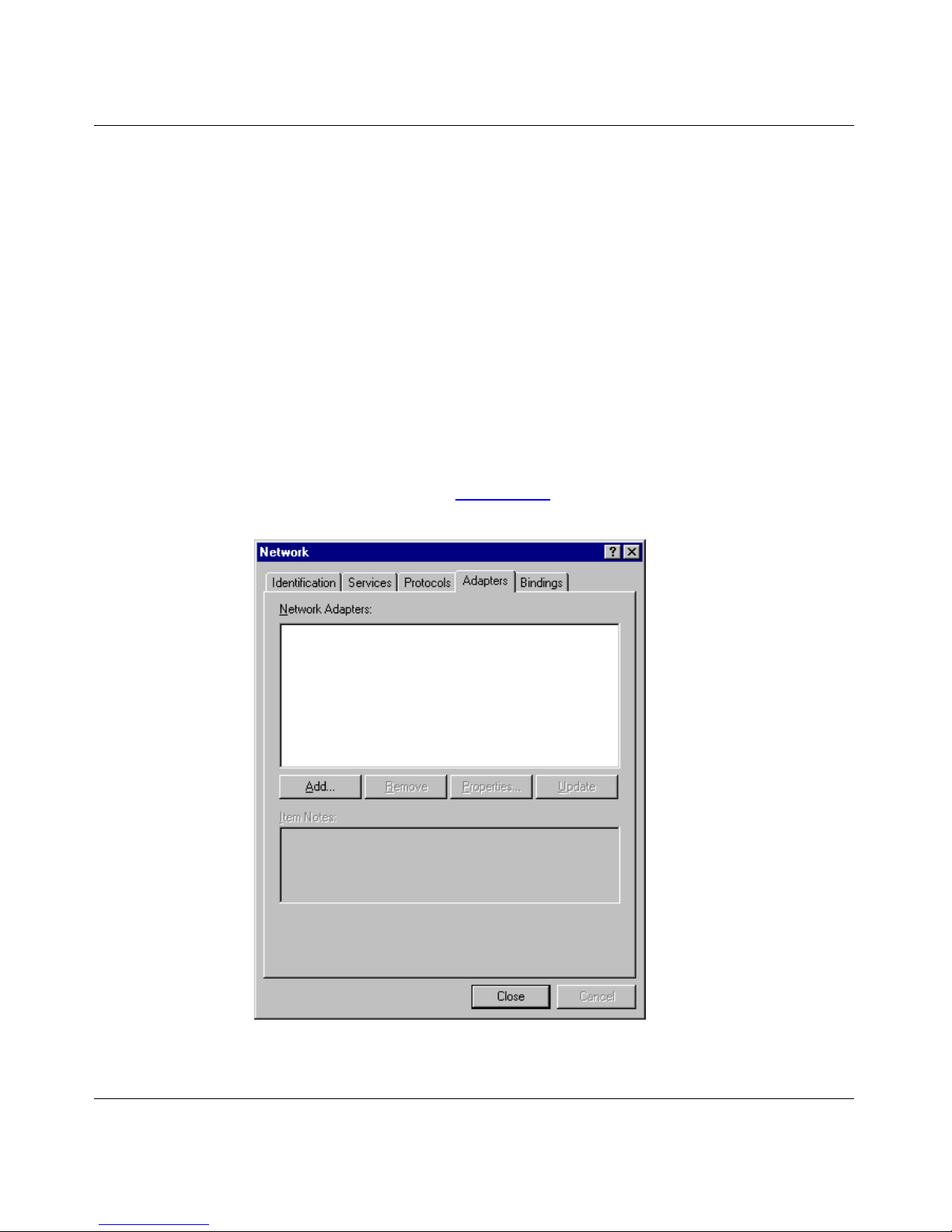
Soft w a r e In stal latio n
Installing the Network Driver in a Windows NT 4.0
Environment
This section describe s the step s required to insta ll the network dri v er softwar e in a
Windows NT 4.0 environment.
To install the network dri ver in a laptop computer:
Be sure that the standard network services are installed on the
1.
Windows NT 4.0 laptop.
From the Windows taskbar, choose Start > Settings > Control Panel.
2.
Double-click Network.
3.
The Network dialog box opens. The Identification tab is displayed by default.
Select the Adapters tab (Figure 3-28).
4.
Figure 3-28. Network Dialog Box—Adapters Tab
206380-A
3-23
Page 52

Installation and Reference for the BayStack 22 PC Card Adapter
Click Add.
5.
The Select Network Adapter dialog box opens (Figure 3-29
Figure 3-29. Select Network Adapter Dialog Box
).
Click Have Disk.
6.
Place the
7.
BayStack 22 PCMCIA Card Adapter Software & Documentation
CD into the CD drive of your computer.
The Insert Disk dialog box opens (Figure 3-30
Figure 3-30. Insert Disk Dialog Box
).
3-24
206380-A
Page 53

Soft w a r e In stal latio n
Specify the lett er o f the dr ive into w hich you insta lled the C D.
8.
Typically the CD drive is letter D.
Click OK.
9.
The Select OEM Option dialog box (Figure 3-31
Figure 3-31. Select OEM Option Dialog Box
Select the BayStack 22 PC Card Adapter.
10.
) opens.
206380-A
3-25
Page 54

Installation and Reference for the BayStack 22 PC Card Adapter
Click OK.
11.
The Wi ndows NT Configuration dialog box opens ( Figure 3-32
Figure 3-3 2. W i nd ow s NT Conf i guration Di alo g B ox
).
Set the following configur at ion parameters, or accept the def ault settings:
• IRQ level—Inter rupt request level. IRQ Level 3 is the default.
• I/O Port Address—Input /Output memory addres s for the lapto p compu ter.
The BayStack 22 network driver inst al lation for Windows NT does not
automatically specifyn this address. You must configure it manually.
• Connection Type—Select one of the following setti ngs:
— AutoSense—Select the default Aut oSense settin g if you want the por t
to use the fastest speed suppor ted by the attached device.
— 100 or 10 half-duplex mode—Use these settings for 100 Mb/s and
10 M b/s Ethernet hubs.
— 100 or 10 half- or f ull-duple x mode—Use these settings for 100 Mb/s
and 10 Mb/s Etherne t switc hes.
3-26
206380-A
Page 55

Configuring the Windows NT Environment
This section provides instructions for configuring the BayStack 22 network card
on the network after you have installed the BayStack 22 network driver on a
Windows NT laptop computer.
To configure the network properties for your Windows NT laptop:
From the Windows taskbar, choose Start > Settings > Control Panel.
1.
Double-click Network.
2.
The Identification tab is displayed by default.
Select the Bindi ng s ta b (Figure 3-33).
3.
Soft w a r e In stal latio n
Figure 3-33. Bindings Tab
The all services selection is the default.
206380-A
3-27
Page 56

Installation and Reference for the BayStack 22 PC Card Adapter
Select all adapters (Figu re 3-34).
4.
3-28
Figure 3-34. Bindings Tab —All Adapters Selection
All of the adapters installed in your computer display.
Verify that the BayStack 22 PC Card Adapter is displayed and selected.
5.
Click OK.
6.
The Network dialog box is displayed a gain.
206380-A
Page 57

Soft w a r e In stal latio n
Select the IP address tab (Figure 3-35).
7.
206380-A
Figure 3-35. IP Address Tab
If the computer has a static IP address, specify the IP address, subnet
8.
mask, and default gateway of you r computer.
You can also choose the “Obtain an IP address from a DHCP server” option if
the computer does not have a static IP address.
Click OK.
9.
3-29
Page 58

Installation and Reference for the BayStack 22 PC Card Adapter
Select the DNS tab (Figure 3-36) to configure point-to-point parameters if
10.
you are using an Internet service provider (ISP) .
3-30
Figure 3-36. DNS Tab
Enter the host name and domain of your computer.
11.
Enter the DNS service and domain suffix search order information f or
12.
your ISP.
Click OK.
13.
206380-A
Page 59

Soft w a r e In stal latio n
Select the WINS Address tab (Figure 3-37).
14.
206380-A
Figure 3-37. WINS Address Tab
Enter the IP address of your primary and secondary WINS servers.
15.
Click OK.
16.
Restart your system if prompted.
17.
3-31
Page 60

Installation and Reference for the BayStack 22 PC Card Adapter
Installing t he Network Driver in a Novell NetWare 4.x
Environment
This section describes the steps required to install the Ba yStack 22 netw ork drive r
software in a Novell NetWare version 4.x environment. You must install and
configur e the software on your Novell server and client. Your laptop c omputer is
considered the client.
If you are install ing the BaySt ack 22 network dr i ve r sof tware in a Nov ell NetWare
version 3.1 2 environment, refer to the Readme.txt fil e on the BayStack 22
PCMCIA Card Adapter Software & Documentation CD.
Installing the Network Card in a Novell NetWare Server
This section describes the steps required to install the Ba yStack 22 netw ork drive r
software in your Novell NetWare 4.x server.
Your laptop computer must have the follo wing installed prior to installing the
BayStack 22 network driver software:
• Ba y Stack 22 PC Card Ad ap ter
• MS-DOS operating system
• Novell Ne tWare 4.x server software
To install the BayStack 22 networ k driver in your Novell NetWare 4.x server:
Insert the
1.
BayStack 22 PCMCIA Card Adapter Sof tware & Documenta tion
CD into the CD drive of your server.
Verify that the following files are located in the Novell NetWare server
2.
directory.
• \NETWARE\SERVER\4.X\MSM.NLM
• \NETWARE\SERVER\ETHERTSM.NLM
If the files listed in step 2 are not located in the server directory , copy
3.
these files from the
Documentation
BayStack 22 PCMCIA Card Adapter Software &
CD.
3-32
206380-A
Page 61

Soft w a r e In stal latio n
Copy the following file from the
4.
Software & Documentation
BayStack 22 PCMCIA Card Adapter
CD to the root directory.
• \ENABLER\B22ENA10.EXE
You can also run the BS22ENA10.EXE progr am from the BayStack 22
PCMCIA Card Adapter Software & Documentation CD instead of copying
the program to your root directo ry.
Access a DO S prom pt s creen.
5.
From the DOS prompt you must run the BS22ENA10.EXE program before
installi ng the BaySta ck 22 network driv e r.
Enter the following syntax:
6.
B22ENA10 [/IRQ:x][/IOP:xxx]
where:
• IRQ is the interrupt number used specifically for the BayStack 22
network card. This number must not be used by any other device in the
system. The default IRQ value is 3.
• IOP is the starting Input/Output (I/ O) port address, in hexadeci mal
format. The BayStack 22 network card requires 32 consecutive free
I/O port addresses. The default IOP value is 0x300.
206380-A
For example, the following command enables a BayStack 22 network card
havin g an IRQ v alue of 5 and an IOP value of 300:
B22ENA10 /IRQ:5 /IOP:300
Change to the Novell NetWare server directory.
7.
For instance, type the command:
CD\NWSERVER
Type:
8.
SERVER
Press Enter.
9.
At the server prompt, enter:
10.
LOAD INSTALL
The NetWare Server Installation Utility loads.
From the Installation Options menu, select Driver options.
11.
3-33
Page 62

Installation and Reference for the BayStack 22 PC Card Adapter
Press Enter.
12.
From the Driver Opti ons menu, select Configure network drivers.
13.
Press Enter.
14.
From the Additional Driver Actions menu, select Select a driver.
15.
Press Enter.
16.
Press Insert (<IN S > ) to insta l l an un lis ted driver.
17.
By default, your a: drive is scanned.
Press <F3> to specify another path or drive.
18.
Specify the directory on the
19.
& Documentation
For ex ample , type
Insert the
20.
BayStack 22 PCMCIA Card Adapter Sof tware & Documenta tion
CD where the Novell NetWare drivers are located .
D:\NETWARE\SERVER
BayStack 22 PC MCIA Card A dapter Software
.
CD in the CD drive of your server.
Press Enter.
21.
The following file is automati cally copied from the BayStack 22 PCMCIA
Car d Adapter Software & Documentation CD to your server:
• \NETWARE\SERVER\B22LAN10.LAN
From the Select a driver to install: menu, select Nortel 22 10/100
22.
PCMCIA Fast Ethernet Adapter.
Press Enter.
23.
The “Do you want to copy driver B22LAN10.LAN (Y)(N)” message is
displayed.
Select Yes.
24.
Proceed to the next section, “Specifying Driver Para m e ter s ” on
25.
page 3-35, if you want to specify driver parameters or complete the
following 3 steps.
Type:
26.
down
The server closes.
3-34
206380-A
Page 63

Soft w a r e In stal latio n
Type:
27.
exit
Your system returns to the DOS prompt.
In the DOS prompt, type:
28.
server
The BayStack 22 network card and the server on the Novell NetW are network
open and are functioning.
Note:
Each time you reboot your server , you must run the B22ENA10.EXE
program to enable the BayStack 22 network card.
Specifying Driver Parameters
The BayStack 22 network driver inst al ls with default parameter s. You can set
specific driv er parameters for the driver if you do not want to use the default
settings.
To set specific driver parameters:
From the Board BayStack 22 (Driver B22LAN10) Actions menu, select
1.
“Select/Modify driver parameters and protocols.”
Press Enter.
2.
The default protocol is IPX. You can also select TCP/IP or AppleTalk.
Select a protocol from the available options.
3.
Specify the slot number (slot#).
4.
Select “Save parameter and load select driver.”
5.
If you select the IPX protocol, the network number (network #) is randomly
generated.
Press Enter at each of the following four prompts:
6.
• 802.3
• 802.2
•SNAP
• Ethernet II
206380-A
3-35
Page 64

Installation and Reference for the BayStack 22 PC Card Adapter
Type:
7.
down
The server closes.
Type:
8.
exit
Your system returns to the DOS prompt.
In the DOS prompt, type:
9.
server
The BayStack 22 network card and the server on the Novell NetW are network
open and are functioning.
Note:
Each time you reboot your server , you must run the B22ENA10.EXE
program to enable the BayStack 22 network card.
Installing the Network Card in a Novell NetWare Client
This section describes the steps required to install the Ba yStack 22 netw ork drive r
software on your Novell NetWare 4.x laptop computer, or client. You must have
already installed a BayStack 22 PC Card Adapter in your laptop.
To install the BayStack 22 networ k driver on your Novell NetWare 4.x client:
Verify tha t your Ba ySta c k 22 network card i s proper ly in sta l led in your
1.
Novell NetWare 4.x laptop.
Insert the
2.
CD into your laptop.
Access a DO S prom pt s creen.
3.
From the DOS prompt you must run the BS22ENA10.EXE program before
installi ng the BaySta ck 22 network driv e r.
BayStack 22 PCMCIA Card Adapter Sof tware & Documenta tion
3-36
206380-A
Page 65

Soft w a r e In stal latio n
Enter the following syntax:
4.
B22ENA10 [/IRQ:x][/IOP:xxx]
where:
• IRQ is the interrupt number used specifically for the BayStack 22
network card. This number must not be used by any other device in
the system. The default IRQ value is 3.
• IOP is the starting input/output (I/O) port address, in hexidecimal
format. The BayStack 22 network card requires 32 consecutive free
I/O port addresses. The default IOP value is 0x300.
For example, the following command enables a BayStack 22 network card
havin g an IRQ v alue of 5 and an IOP value of 300:
B22ENA10 /IRQ:5 /IOP:300
Note:
If you installed th e EMM386.EXE progr am in CONFIG. SYS, you must
exclude the memory address range D000 to DFFF or D400 to D7FF in the
EMM386.EXE program. The B22ENA10.EXE program uses this memory
address ra nge to read configuration information f rom the BayStack 22 netwo rk
card.
For ex ample , the following commands exclude the required memory address
range:
DEVICE=E MM386.EXE NOE MS X=D400-D7FF
DEVICE=E MM386.EXE NOE MS X=D000-DFFF
Access the Novell NetWare client directory on your clie nt laptop.
5.
From the \NETWARE\DOSODI directory on the
6.
Card Adapter Software & Documentation
LSL.COM
B22ODI10.COM
IPXODI.COM
NETX.EXE
NET.CFG
CD, copy the following files:
BayStack 22 PCMCIA
The STARNET.BAT file in the \NETWARE\DOSODI directory executes the
first four files automatically, in the correct sequence. Refer to “Client Files”
on page B-4
for descriptions of these files.
206380-A
3-37
Page 66

Installation and Reference for the BayStack 22 PC Card Adapter
Press Enter.
7.
You can now log in to your networ k.
8.
Edit the
NET.CFG
file to specify driver parameters, as needed.
You can specify the PORT, IRQ, NWAY, and S10/S10FD/S100/S100FD
parameters.
Refer to Appendix B, “
Novell NetWare Refere n ce Info rm ation, ” fo r sa mpl e
NET.CFG files.
3-38
206380-A
Page 67

This chapte r provides several methods for troubleshooting pr oblems relate d to the
BayStack 22 PC Card A d apt er.
Diagnostic LEDs
Chapter 4
Troubleshooting
Three LEDs on the media coupler of the BayStack 22 netw ork card provide
diagnostic information. The 10 and 100 Mb/s Link LEDs indicate successful
network connectio ns to Ethe rnet and F ast Ethernet de vi ces, respe ctively . The Link
LEDs remain steady if the connection is stable. You should check the RJ-45
connection if the LED is not steady. The Activity LED indicate s active network
traffic.
Table 4-1
Tabl e 4 -1 . LED Indic at io ns
Label Color Activity Description
10M Green On A 10 Mb/s connection has been established.
100M Green On A 100 Mb/s connection has been established.
ACT Green On Heavy network traffic is passi ng through the port.
Green Blinking Network traffic is passing through the connected port.
describes the Link and Activity LED indications.
Off Power is not supplied to the netw ork card, or a 10 Mb/s
connection is not established.
Off Power is not supplied to a network card, or a 100 Mb/s
connection is not established.
The rate of blinking is proportional to the amount of
netw o rk traff ic.
206380-A
4-1
Page 68

Installation and Reference for the BayStack 22 PC Card Adapter
Har dware Issues
Perform the following tasks to check for hardware problems:
• Verify that you are using the correct cables and the correc t cable lengths, as
described in “Cable Requirements
• Make sure the media coupler is firmly connected to the network card and to a
network device.
• Use a different port on the netw ork device.
• Verify that the BayStack 22 networ k car d is fully and fir mly seated in the slot
connector in the co mputer. Check the connector edge s of the card for damage.
• Replace the network card in question with a network card that you are sure
functions properly. Run generic network int erface card diagnostic tests.
• Install the network card in question into another computer and run the tests
again.
• Remove all other netw ork cards from the computer and run the tests again.
If the verification/diagnostic run is not normal, there is probably an interrupt
number conflict. You must manually resolve the conflict by running a CMOS
Setup utility after you have reinstalled the expansion cards.
” on page 1-6.
Software Issues
Perform the following tasks to check for software problems:
• Verify that the proper driver is loaded, as expla ine d in Chapter 3, “
Installation. ” Be s ure y ou foll o wed the directi ons for t he operati ng sy stem you
are running on the computer.
• Check that the new conf igurations match the conf igur ations of the network
devi ce if you have manually configured the speed or mode of the network
card. Nortel Netwo rks recommends setting the network card to
autonegotiation when installin g the networ k drive r.
• Verify that the PCMCIA slot in the computer is an enabled bus- master slot.
Some computers may require that you conf igure the PCMCIA slot to enable
bus mastering. Refer to your computer manual for information about the
PCMCIA BIOS setup pr ogram.
• Verify that your B IOS software correctly supports the PCMCIA Local Bus
Specification, version 2.0 or later. Upgrade your BIOS software if neede d.
4-2
Software
206380-A
Page 69

Troubleshooting
• Determine whether or not the network card slot is deactivated at the BIOS
level. Use the CMOS Setup utility in your computer to provide the option to
activate or deactivate slots.
• Disable the Plug and Play option (PnP) in the BIOS setup program if it is
recommended by your PC manual. Some computer s may requir e you to
perform this task. Incorrectly assigned resou rce s between network cards may
cause problems.
Note:
Always consult your computer manual for information a bout ch anging
motherboard jumper and BIOS settings. If you modify the BIOS settings,
make sure the jumper and BIOS settings match.
• You may need to reserve interrupts and memory addresses for installed
Industry Standard Architecture (ISA) cards to prevent PCMCIA cards from
using the same settings. Ref er to your PC manual for instructions.
206380-A
4-3
Page 70

Page 71

Tables in this appendix provide technic a l product specific ations and list the
av a ilable software drivers for the BayStack 22 PC Card Adapter.
Product Specifications
Appendix A
Technical Specifications
Table A-1 lists technical spec ifications for the BayStack 22 network card.
Table A-1. Technical Specifications
Standards Compatibility
EMC Compliance
CE Mark: EN50081-1
Emissions: FCC Class B
Physical Dimensions
Network Card: 86 x 54 x 5.0 mm (3.37 x 2.13 x 0.2 in)
Media Coupler: 222 mm (8.75 in) (including connectors)
Weight
Environment
Operating: 0° to 55
IEEE 802.3 10BASE-T
IEEE 802.3u 100BASE-TX
PC Card 95 CardBus Standard
EN55022
IEC1000-4-2/3/4/6
VCCI Class B
EN55022 (CISPR 22) Class B
30g (1.94 oz)
°
C (32° to° 131
°
F)
Humidity: 10% to 9%, noncondens ing
Power Consumption
206380-A
+5 V DC at 145mA (Standby)
+5 V DC at 300mA (Transmit)
A-1
Page 72

Installation and Reference for the BayStack 22 PC Card Adapter
Table A-1. Technical Specifications
Network Interface
10BASE-T: RJ-45 (UTP Cable, Categories 3, 4, 5)
100BASE-TX: RJ-45 (UTP Cable, Category 5)
Data Interface
I/O Address
System Clock
Interrupt
LED Indicators
32-bit bus-mastering PCI
Det ected by B I O S or Car d S erv ice
20 to 33 MHz
INT A, mapping to BIOS IRQ setup
10 Mb/s, 100 Mb/s, Activity
Software Drivers
Table A-2 lists the av ailable software driv ers f or the BayStack 22 network card.
Refer to Chapter 3, “Software Inst allation
Windows-base d drive rs. Refer to the README files assoc iated with other drive r s
for installation instructions.
Table A-2. Available Software Drivers
Driver Compatible Operating Systems
Network Device Interface
Specifications (NDIS)
Microsoft Windows 95, Windows 98
Microsoft Windows NT 3. 51, 4.0
Microsoft Windows for Workgroups 3.11
Microsoft LAN Mana ger 2.x
Banyan VINES
DEC Pathworks
IBM TCP/IP for DOS
LAN Support program
SUN PC-NFS
,” for installation instructions for the
NetWare Open Data-Link
Inter face (ODI)
Packet IFTP P C /T C P
A-2
Novel l Net Ware 3.x, 4.x
NetWare LAN Workplace TCP/IP
Novell LAN Analyzer for NetWar e
Novel l Personal NetWare
NCSA TCP/IP
206380-A
Page 73

Appendix B
Novell NetWare Reference Information
This appendix provides reference files for your Novell NetWare 4.x operating
system. Server and clie nt information is provided in the following sections.
If you are installing the BayStack 22 PCMCIA Network Driver software in a
Novell NetWare version 3.12 envir onm ent, refer to the Readme.txt file on the
BayStack 22 PCMCIA Card Adapter Software & Documentation CD.
Novell NetWare Server Files
This section provides information about the Novell NetWare 4.x files in general,
and specifically about the AUTOEXEC.NCF file parameters.
File Descriptions
Table B-1 provides descr iptions of the Novell NetWare server files.
Tabl e B -1. Serv er Fi les
File Name Description
README.TXT A summary of the BayStack 22 netwo rk driver inst allation for the
Novel l Net Ware server.
B22ENA10.EXE Enabling DOS program for the BayStack 22 network driver.
B22LAN10.LAN BayStack 22 32-bit ODI server driver.
B22LAN10.LDI BayStack 22 netw ork driver installation information.
ETHERTSM.NLM NeW are Serve r 3.1X, 4.1X LAN driv er Topology Specific Module
(TSM) for Ethernet.
3.1X\NBI31X.NLM NetWare Server 3.1X Bus Interface module.
3.1X\MSM31X.NLM NetWare Server 3.1X LAN driver Media Support Module (MSM).
4.X\MSM.NLM NetWare Server 4.x LAN driver Media Support Module (MSM).
206380-A
B-1
Page 74

Installation and Reference for the BayStack 22 PC Card Adapter
Sample
AUTOEXEC.NCF
Files
Sample file s and file parameters are pr ovided in this section.
The following files are typically part of the AUTOEXEC.NCF file:
LOAD C:NBI
LOAD C:MSM
LOAD C:ETHERTSM
LOAD C:B22LAN10 FRAME=ETHERNET_802.2 NAME=E_8022
LOAD C:B22LAN10 FRAME=ETHERNET_802.3 NAME=E_8023
LOAD C:B22LAN10 FRAME=ETHERNET_II NAME=E_II
LOAD C:B22LAN10 FRAME=ETHERNET_SNAP NAME=E_SNAP
BIND IPX E_8022 NET=10
BIND IPX E_8023 NET=20
BIND IPX E_IINET=30
BIND IPX E_SNAP NET=40
AUTO.EXEC.NCF
File Parameters
This section describes the AUTOEXEC.NCF file para me te rs FRAME, INT,
PORT, and S10/S10FD/S100/S100FD.
FRAME Parameter
The FRAME parameter specifies which type of frame is used by the BaySta ck 22
network driver.
Accepted values include:
• Ethernet_802.3
• Ethernet_802.2
• Ethernet_II
• Ethernet_SN AP
Multiple frame types can be enabled by loading the same driver with dif f erent
FRAME type parameters.
B-2
206380-A
Page 75

Novell NetWare Reference Information
The following are exa mpl es of typical FRAME parameters:
LOAD B22LAN10 FRAME=ETHERNET_802.2
LOAD B22LAN10 FRAME=ETHERNET_802.3
LOAD B22LAN10 FRAME=ETHERNET_II
LOAD B22LAN10 FRAME=ETHERNET_SNAP
INT Parameter
The INT par am eter refers to the inter rup t (IR Q) value us ed by the BaySt ac k 22
network card. The INT value must match the IRQ value you specify when
enabling the B22ENA10 pr ogram. You must use a DOS prompt to enable this
program before you access your Novell NetWare 4.x server. Refer to “Installing
the Network C ard in a Novell NetWare Server” on page 3-32 for instructions.
The following is an example of a typical INT parameter:
LOAD B22LAN10 INT=3 FRAME=ETHERNET_802.2
PORT Pa rameter
The PORT parameter reflects the input/output (I/O) port address of the ser ver.
The PORT value must match the IOP value you specify when enabling the
B22ENA10 program. You must use a DOS prompt to enable this program bef ore
you access your No vell NetWare 4.x server. Refer to “
Installing the Networ k Card
in a Novell NetWare Server” on page 3-32 for instructions.
The following is an example of a typical PORT parameter:
LOAD B22LAN10 INT=3 PORT=300 FRAME=ETHERNET _802.2
206380-A
B-3
Page 76

Installation and Reference for the BayStack 22 PC Card Adapter
S10, S1 0F D, S100, S100FD Para meters
The S10, S10FD, S100, S100FD parameters specif y the connection type of the
BayStack 22 network card. The connection type includes transmission speed
(10 or 100 Mb/s) and full- or half-duplex operation. These parameters are
mutually ex cl usive; you can select only one parameter at a time from the
command line. I f you do not select an y of these paramet ers, the defa ult connecti on
type is autonegotiation. Table B-2
Tabl e B - 2. Serv er C onnection Type Parameters
Parameter Connection Type
S10 10 Mb/s, half-duplex
S10FD 10 Mb/s, ful l-duple x
S100 100 Mb/s, half-duplex
S100FD 100 Mb/s, full -duplex
describes each p ara meter.
The following is an example of a connection type parameter set to 10 Mb/s
transmission spe ed and full-duplex mode:
LOAD B22LAN10 INT=3 PORT=300 FRAME=ETHERNET _802.2 S1 0FD
Novell NetWare Client Files
This section provides information about client and NET.CFG files.
Client Files
Table B-3 briefly describes the files you use when installing the BayStack 22
network driver into your Novell NetWare client.
Tabl e B - 3. Client Fil e s
Command Description
LSL.COM Supports the OSI link support layer
B22ODI10.COM Client BayStack 22 network driver
IPXODI.COM Default protocol stack
file
NETX.EXE Serv er connection
NET.CFG Optional configuration fil e
B-4
206380-A
Page 77

Novell NetWare Reference Information
NET.CFG
Files and Parameters
This section contains a sample NET.CFG file and describes the parameters of this
file.
Sample
You can specify the DOC ODI driver in the NET.CFG file. The following is a
sample NET. CFG fil e:
Protocol
LINK DRIVER B22ODI10
NET.CFG
Bind B22ODI10
Port 300
IRQ 5
; NWAY
; S10
; S10FD
; S100
; S100FD
File
NetWare DOS Requester
FIRST NETWORK DRIVE = F
NETWARE PROTOCOL = NDS BIND
NET.CFG
File Parameters
This section describes the NET.CFG file parameters PORT, IRQ, NWAY, and
S10/S10FD/S100/S 100FD.
PORT Pa rameter
The PORT parameter specifies the input/output (I/O) address in hexadecimal
format. This value must match the value reported by the B22ENA10.EXE
program. The defaul t value is 300.
IRQ Parame ter
This parameter specifies the interrupt ( IRQ) value for the BayStack 22 networ k
card. This va lue must match the value reported by the B22ENA10.EXE program.
The default value is 5.
206380-A
B-5
Page 78

Installation and Reference for the BayStack 22 PC Card Adapter
NWAY Parameter
The NWAY parameter specifies the connection type as auto-negotiation, which is
also the default connection type.
S10/S10FD/S100/S100FD P aramet er s
The S10, S10FD, S100, and S100FD parameters spec if y the connection type of
the BayStack 22 network card. The connection type includes tra nsmission speed
(10 or 100 Mb/s) and full- or half-duplex operation. These parameters are
mutually ex cl usive; you can select only one parameter at a time from the
command line. I f you do not select an y of these paramet ers, the defa ult connecti on
type is autonegotiation (NWAY). Table B-4 describes each parameter.
Tabl e B -4. Client Connectio n Type Parameters
Parameter Connection Type
S10 10 Mb/s, half-duplex
S10FD 10 Mb/s, ful l-duple x
S100 100 Mb/s, half-duplex
S100FD 100 Mb/s, full -duplex
B-6
206380-A
Page 79

Numbers
10 Mb/s Ethernet cables, 1-6
100 Mb/s Ethernet cables, 1-6
10BASE-T/100BASE-TX ports, 1-3
A
autonegotiation, 1-3
C
cables
10 Mb/s Ethernet, 1-6
100 Mb/s Ethernet, 1-6
requirements, 1-6
connect ors
10BASE-T/100BASE-TX, 1-3
15-pin, 1-3
68-pin, 1-2
media coupler, 1-3
RJ-4 5 port, 1-3
conventions, text, xv
customer support, xvi
E
Ethernet cables, 1-6
F
Fast Ethernet cables, 1-6
I
installation
netw ork car d
into a laptop, 2-2
typical, 1-8
IndexIndex
network driver
automatic, 3-1
in a Novell NetWare 4.x environm ent, 3-3 2
in a Windows 95 environment, 3-2
in a Windows 98 environment, 3-11
in a Windows NT environment , 3-23
preinstallation tasks, 3-2
interrupt request, configuring, 3-21
L
LEDs, 1-4
M
medi a co uple r
connecting to Ethernet cable, 2-3
connecting to network card, 2-2
description, 1- 3
N
network card
attaching to media coupler, 2-2
configuring
in a Windows 95 environment, 3-6
in a Windows 98 environment, 3-18
in a Windows NT environment , 3-27
inserting into l aptop, 2-2
installing, 2-2
removing, 2-3
network drivers
installing in a Novell NetWare 4.x environment,
3-32
insta lli ng in other system s, A-2
instal ling in W indows envi ronments, 3-1
206380-A
Index-1
Page 80

Novell NetWare
client file descriptions, B-4
NET . CFG file, B-5
NET.CFG parameters, B-5
server file examples, B-1
specifying driver parameters, 3-35
O
operating environments, 1-6
R
requirements
cable, 1-6
syste m , 1- 5
S
support, Nortel Networks, xvi
system requirements, 1-5
P
package contents, 2-1
ports
autonegotiation, 1-3
Etherne t 10BASE-T/100BASE-TX, 1-3
RJ-45, 1-3
product
components, 1-2
support, xvi
T
techni cal publications, xvi
technical specifications, A-1
techni cal support, xvi
text conventions, xv
troubl eshooting
diagnostic LEDs, 4- 1
hardware, 4-2
software, 4-2
typica l application, 1-8
Index-2
206380-A
 Loading...