

Page 1

TM
Alteon OS
Command Reference
Nortel 10Gb Uplink Ethernet Switch Module for IBM BladeCenter®
Version 1.2
Part Number: BMD00007, November 2007
2350 Mission College Blvd.
Suite 600
Santa Clara, CA 95054
www.bladenetwork.net
Page 2

Alteon OS Command Reference
Copyright © 2007 Blade Network T echnologies, Inc., 2350 Mission College Blvd., Suite 600, Santa Clara,
California, 95054, USA. All rights reserved. Part Number: BMD00007.
This document is protected by copyright and distributed under licenses restricting its use, copying,
distribution, and decompilation. No part of this document may be reproduced in any form by any means
without prior written authorization of Blade Network T echnologies, Inc. Documentation is provided “as
is” without warranty of any kind, either express or implied, including any kind of implied or express
warranty of non-infringement or the implied warranties of merchantability or fitness for a particular
purpose.
U.S. Government End Users: This document is provided with a “commercial item” as defined by F AR
2.101 (Oct. 1995) and contains “commercial technical data” and “commercial software documentation” as
those terms are used in F AR 12.211-12.212 (Oct. 199 5). Government End Users are authorized to use this
documentation only in accordance with those rights and restrictions set forth herein, consistent with F AR
12.211- 12.212 (Oct. 1995), DF ARS 227 .7202 (JUN 1995) and DF ARS 252.227-7015 (Nov . 1995).
Blade Network T echnologies, Inc. reserves the right to change any products described herein at any time,
and without notice. Blade Network T echnologies, Inc. assumes no responsibility or liability arising from
the use of products described herein, except as expressly agreed to in writing by Blade Network
T echnologies, Inc. The use and purchase of this product does not convey a license under any patent rights,
trademark rights, or any other intellectual property rights of Blade Network T echnologies, Inc.
Originated in the USA.
Alteon OS, and Alteon are trademarks of Nortel Networks, Inc. in the United States and certain other
®
countries. Cisco
and EtherChannel® are registered trademarks of Cisc o Systems, Inc. in the United S tates
and certain other countries. Any other trademarks appearing in this manual are owned by their respective
companies.
2 BMD00007, November2007
Page 3

Contents
Preface 13
Who Should Use This Book 14
How This Book Is Organized 15
Typographic Conventions 16
How to Get Help 17
The Command Line Interface 19
Connecting to the Switch 20
Management Module Setup 20
Factory-Default vs. MM assigned IP Addresses 20
Default Gateway 21
Configuring management module for switch access 21
Connecting to the Switch via Telnet 23
Running Telnet 23
Establishing an SSH Connection 24
Running SSH 25
Accessing the Switch 26
Setup Versus CLI 28
Command Line History and Editing 29
Idle Timeout 29
First-Time Configuration 31
Using the Setup Utility 32
Information Needed For Setup 32
Starting Setup When You Log In 33
Stopping and Restarting Setup Manually 34
Stopping Setup 34
Restarting Setup 34
Setup Part 1: Basic System Configuration 34
Setup Part 2: Port Configuration 36
BMD00007, November 2007 3
Page 4

Alteon OS Command Reference
Setup Part 3: VLANs 38
Setup Part 4: IP Configuration 39
IP Interfaces 39
Default Gateways 40
IP Routing 41
Setup Part 5: Final Steps 41
Optional Setup for Telnet Support 42
Setting Passwords 43
Changing the Default Administrator Password 43
Changing the Default User Password 45
Menu Basics 47
The Main Menu 48
Menu Summary 49
Global Commands 50
Command Line History and Editing 53
Command Line Interface Shortcuts 54
Command Stacking 54
Command Abbreviation 54
Tab Completion 54
The Information Menu 55
Information Menu 56
System Information 58
SNMPv3 System Information Menu 59
SNMPv3 USM User Table Information 61
SNMPv3 View Table Information 62
SNMPv3 Access Table Information 63
SNMPv3 Group Table Information 64
SNMPv3 Community Table Information 64
SNMPv3 Target Address Table Information 65
SNMPv3 Target Parameters Table Information 66
SNMPv3 Notify Table Information 67
SNMPv3 Dump Information 68
BladeCenter Chassis Information 69
General System Information 70
Show Recent Syslog Messages 72
User Status 73
Contents BMD00007, November 2007
4
Page 5

Layer 2 Information 74
FDB Information 76
Show All FDB Information 77
Clearing Entries from the Forwarding Database 77
Link Aggregation Control Protocol Information 78
Show all LACP Information 78
GVRP Information 79
Show GVRP VLAN Database Information 80
Show GID State Machine Information 81
Show GID Port Ring Information 82
802.1x Information 83
Spanning Tree Information 85
RSTP/MSTP Information 88
Common Internal Spanning Tree Information 91
Trunk Group Information 93
VLAN Information 94
Layer 3 Information 95
IP Routing Information 97
Show All IP Route Information 98
ARP Information 100
Show All ARP Entry Information 101
ARP Address List Information 102
BGP Information 102
BGP Peer information 103
BGP Summary information 103
Show all BGP Information 104
OSPF Information 105
OSPF General Information 106
OSPF Interface Information 107
OSPF Database Information 107
OSPF Information Route Codes 109
Routing Information Protocol Information 110
RIP Routes Information 110
Show RIP User Configuration 111
IP Information 112
IGMP Multicast Group Information 113
IGMP Group Information 114
IGMP Multicast Router Port Information 114
IGMP Mrouter Information 115
VRRP Information 116
Quality of Service Information 117
Alteon OS Command Reference
Contents
5BMD00007, November 2007
Page 6

Alteon OS Command Reference
802.1p Information 117
Access Control List Information 119
Link Status Information 120
Port Information 121
Fiber Port Transceiver Status 123
Information Dump 123
The Statistics Menu 125
Statistics Menu 125
Port Statistics 127
802.1x Authenticator Statistics 128
802.1x Authenticator Diagnostics 129
Bridging Statistics 131
Ethernet Statistics 133
Interface Statistics 136
Interface Protocol Statistics 138
Link Statistics 138
Layer 2 Statistics 139
FDB Statistics 139
LACP Statistics 141
GVRP Statistics 142
Layer 3 Statistics 144
IP Statistics 147
Route Statistics 149
ARP statistics 149
DNS Statistics 150
ICMP Statistics 150
TCP Statistics 153
UDP Statistics 155
IGMP Statistics 156
OSPF Statistics 157
OSPF Global Statistics 158
VRRP Statistics 162
Routing Information Protocol Statistics 163
Management Processor Statistics 164
MP Packet Statistics 165
TCP Statistics 166
UCB Statistics 167
CPU Statistics 167
ACL Statistics 168
ACL Statistics 168
Contents BMD00007, November 2007
6
Page 7

SNMP Statistics 169
NTP Statistics 173
Statistics Dump 174
The Configuration Menu 175
Configuration Menu 176
Viewing, Applying, and Saving Changes 177
Viewing Pending Changes 177
Applying Pending Changes 178
Saving the Configuration 178
System Configuration 179
System Host Log Configuration 182
SSH Server Configuration 183
RADIUS Server Configuration 185
TACACS+ Server Configuration 187
LDAP Server Configuration 190
NTP Server Configuration 192
System SNMP Configuration 193
SNMPv3 Configuration 195
User Security Model Configuration 197
SNMPv3 View Configuration 198
View-based Access Control Model Configuration 199
SNMPv3 Group Configuration 201
SNMPv3 Community Table Configuration 202
SNMPv3 Target Address Table Configuration 203
SNMPv3 Target Parameters Table Configuration 204
SNMPv3 Notify Table Configuration 205
System Access Configuration 206
Management Networks Configuration 208
User Access Control Configuration 209
System User ID Configuration 210
Strong Password Configuration 211
HTTPS Access Configuration 212
Port Configuration 213
Port Link Configuration 215
Temporarily Disabling a Port 216
Port ACL Configuration 216
Alteon OS Command Reference
Contents
7BMD00007, November 2007
Page 8

Alteon OS Command Reference
Layer 2 Configuration 217
802.1x Configuration 219
802.1x Global Configuration 220
802.1x Guest VLAN Configuration 222
802.1x Port Configuration 223
Rapid Spanning Tree Protocol/
Multiple Spanning Tree Protocol Configuration 225
Common Internal Spanning Tree Configuration 227
CIST Bridge Configuration 228
CIST Port Configuration 229
Spanning Tree Configuration 231
Spanning Tree Bridge Configuration 233
Spanning Tree Port Configuration 235
Forwarding Database Configuration 237
Static FDB Configuration 237
GVRP Configuration 238
GVRP Port Configuration 239
Trunk Configuration 240
IP Trunk Hash Configuration 241
IP Trunk Hash 241
LACP Configuration 243
LACP Port Configuration 244
Layer 2 Failover Configuration 245
Failover Trigger Configuration 246
Auto Monitor Configuration 247
VLAN Configuration 248
Protocol-based VLAN Configuration 250
Private VLAN Configuration 252
Layer 3 Configuration 253
IP Interface Configuration 255
Default Gateway Configuration 256
IP Static Route Configuration 258
IP Multicast Route Configuration 259
ARP Configuration 260
ARP Static Configuration 261
IP Forwarding Configuration 262
Network Filter Configuration 263
Routing Map Configuration 264
IP Access List Configuration 266
Autonomous System Filter Path 267
Contents BMD00007, November 2007
8
Page 9

Routing Information Protocol Configuration 268
Routing Information Protocol Interface Configuration 269
Open Shortest Path First Configuration 271
Area Index Configuration 273
OSPF Summary Range Configuration 274
OSPF Interface Configuration 275
OSPF Virtual Link Configuration 277
OSPF Host Entry Configuration 278
OSPF Route Redistribution Configuration 279
OSPF MD5 Key Configuration 280
Border Gateway Protocol Configuration 281
BGP Peer Configuration 283
BGP Redistribution Configuration 285
BGP Aggregation Configuration 286
IGMP Configuration 287
IGMP Snooping Configuration 288
IGMP Version 3 Configuration 289
IGMP Relay Configuration 290
IGMP Relay Multicast Router Configuration 291
IGMP Static Multicast Router Configuration 292
IGMP Filtering Configuration 293
IGMP Filter Definition 294
IGMP Filtering Port Configuration 295
IGMP Advanced Configuration 296
Domain Name System Configuration 297
Bootstrap Protocol Relay Configuration 298
VRRP Configuration 299
Virtual Router Configuration 301
Virtual Router Priority Tracking Configuration 303
Virtual Router Group Configuration 304
Virtual Router Group Priority Tracking Configuration 306
VRRP Interface Configuration 307
VRRP Tracking Configuration 308
Quality of Service Configuration 309
802.1p Configuration 310
DSCP Configuration 311
Access Control List Configuration 312
ACL Configuration 313
Ethernet Filtering Configuration 314
IP version 4 Filtering Configuration 315
TCP/UDP Filtering Configuration 317
Alteon OS Command Reference
Contents
9BMD00007, November 2007
Page 10

Alteon OS Command Reference
ACL Metering Configuration 318
Re-Mark Configuration 319
Re-Marking In-Profile Configuration 320
Update User Priority Configuration 321
Re-Marking Out-of-Profile Configuration 322
Packet Format Filtering Configuration 322
ACL Group Configuration 323
Port Mirroring Configuration 324
Port-Mirroring Configuration 325
Setup 326
Dump 326
Saving the Active Switch Configuration 327
Restoring the Active Switch Configuration 327
The Operations Menu 329
Operations Menu 330
Operations-Level Port Options 332
Operations-Level Port 802.1x Options 333
Operations-Level VRRP Options. 334
Operations-Level IP Options 334
Operations-Level BGP Options 335
Protected Mode Options 336
The Boot Options Menu 339
Boot Menu 340
Scheduled Reboot of the Switch 340
Scheduled Reboot Menu 340
Updating the Switch Software Image 341
Loading New Software to Your Switch 341
Using the BBI 341
Using the CLI 343
Selecting a Software Image to Run 344
Uploading a Software Image from Your Switch 345
Selecting a Configuration Block 346
Resetting the Switch 347
Accessing the ISCLI 347
The Maintenance Menu 349
Maintenance Menu 350
System Maintenance 352
Contents BMD00007, November 2007
10
Page 11

Forwarding Database Maintenance 353
Debugging Options 354
ARP Cache Maintenance 355
IP Route Manipulation 356
IGMP Maintenance 357
IGMP Group Maintenance 358
IGMP Multicast Routers Maintenance 359
Uuencode Flash Dump 360
TFTP System Dump Put 361
Clearing Dump Information 361
Panic Command 362
Unscheduled System Dumps 362
Alteon OS Syslog Messages 363
Alteon OS SNMP Agent 375
Working with Switch Images and
Configuration Files 378
Loading a new switch image 379
Loading a saved switch configuration 380
Saving the switch configuration 380
Saving a switch dump 381
Alteon OS Command Reference
Glossary 383
Index 385
Contents
11BMD00007, November 2007
Page 12

Alteon OS Command Reference
Contents BMD00007, November 2007
12
Page 13

Preface
The Alteon OS Command Reference describes how to configure and use the Alteon OS software with your Nortel 10Gb Uplink Ethernet Switch Module (GbE Switch Module).
For documentation on installing the switches physically, see the Installation Guide for your
GbE Switch Module. For details about configuration and operation of your GbE Switch Module, see the Alteon OS Application Guide.
BMD00007, November 2007 13
Page 14

Alteon OS Command Reference
Who Should Use This Book
This Command Reference is intended for network installers and system administrators engaged
in configuring and maintaining a network. The administrator should be familiar with Ethernet
concepts, IP addressing, the IEEE 802.1d Spanning Tree Protocol, and SNMP configuration
parameters.
Preface BMD00007, November 2007
14
Page 15

Alteon OS Command Reference
How This Book Is Organized
Chapter 1 “The Command Line Interface,” describes how to connect to the switch and access
the information and configuration menus.
Chapter 2 “First-Time Configuration
,” describes how to use the Setup utility for initial
switch configuration and how to change the system passwords.
Chapter 3 “Menu Basics
,” provides an overview of the menu system, including a menu map,
global commands, and menu shortcuts.
Chapter 4 “The Information Menu,” shows how to view switch configuration parameters.
Chapter 5 “The Statistics Menu,” shows how to view switch performance statistics.
Chapter 6 “The Configuration Menu,” shows how to configure switch system parameters,
ports, VLANs, Spanning Tree Protocol, SNMP, Port Mirroring, IP Routing, Port Trunking, and
more.
Chapter 7 “The Operations Menu,” shows how to use commands which affect switch per-
formance immediately , but do not alter permanent switch configurations (such as temporarily
disabling ports). The menu describes how to activate or deactivate optional software features.
Chapter 8 “The Boot Options Menu,” describes the use of the primary and alternate switch
images, how to load a new software image, and how to reset the software to factory defaults.
Chapter 9 “The Maintenance Menu,” shows how to generate and access a dump of critical
switch state information, how to clear it, and how to clear part or all of the forwarding database.
Appendix A, “Alteon OS Syslog Messages,” shows a listing of syslog messages.
Appendix B, “Alteon OS SNMP Agent,” lists the Management Interface Bases (MIBs ) sup-
ported in the switch software.
“Glossary” includes definitions of terminology used throughout t he book.
“Index” includes pointers to the description of the key words used throughout the book.
Preface
15BMD00007, November 2007
Page 16

Alteon OS Command Reference
Typographic Conventions
The following table describes the typographic styles used in this book.
Table 1 Typographic Conventions
Typeface or
Symbol
AaBbCc123 This type is used for names of commands,
AaBbCc123 This bold type appears in command exam-
<AaBbCc123> This italicized type appears in command
[ ] Command items shown inside brackets are
Meaning Example
files, and directories used within the text.
It also depicts on-screen computer output and
prompts.
ples. It shows text that must be typed in
exactly as shown.
examples as a parameter placeholder. Replace
the indicated text with the appropriate real
name or value when using the command. Do
not type the brackets.
This also shows book titles, special terms, or
words to be emphasized.
optional and can be used or excluded as the
situation demands. Do not type the brackets.
View the readme.txt file.
Main#
Main# sys
To establish a Telnet session, enter:
host# telnet <IP address>
Read your User’s Guide thoroughly.
host# ls [-a]
Preface BMD00007, November 2007
16
Page 17

Alteon OS Command Reference
How to Get Help
If you need help, service, or technical assistance, see the “Getting help and technical assistance” appendix in the Nortel 10Gb Uplink Ethernet Switch Module for IBM BladeCenter
Installation Guide.
Preface
17BMD00007, November 2007
Page 18

Alteon OS Command Reference
Preface BMD00007, November 2007
18
Page 19

CHAPTER 1
The Command Line Interface
Your GbE Switch Module (GbESM) is ready to perform basic switching functions right out of the
box. Some of the more advanced features, however, require some administrative configuration
before they can be used effectively.
The extensive Alteon OS switching software included in your switch provides a variety of
options for accessing and configuring the switch:
A built-in, text-based command line interface and menu system for access via a Telnet ses-
sion or serial-port connection
SNMP support for access through network management software such as IBM Director or
HP OpenV iew
Alteon OS Browser-Based Interface (BBI)
The command line interface is the most direct method for collecting switch information and
performing switch configuration. Using a basic terminal, you are presented with a hierarchy of
menus that enable you to view information and statistics about the switch, and to perform any
necessary configuration.
This chapter explains how to access the Command Line Interface (CLI) for the switch.
BMD00007, November 2007 19
Page 20

Alteon OS Command Reference
Connecting to the Switch
You can access the command line interface in any one of the following ways:
Using a Telnet via the management module
Using a Telnet connection over the network
Using a SSH connection to securely log into another computer over a network
Using a serial connection using the serial port on the GbESM
Management Module Setup
The BladeCenter GbE Switch Module is an integral subsystem within the overall BladeCenter
system. The BladeCenter chassis includes a management module (MM) as the central element
for overall chassis management and control.
You can use the 100-Mbps Ethernet port on the management module to configure and manage
the GbE Switch Module. The GbE Switch Module communicates with the management module(s) through its internal port 15 (MGT), which you can access through the Ethernet port on
each management module. The factory default settings will permit only management and control access to the switch module through the Ethern et port on the management module, or the
built-in serial port. You can use the four external Ethernet ports on the switch module for management and control of the switch by selecting this mode as an option through the management
module configuration utility program (see the applicable BladeCenter Installation and User’s
Guide publications for more information).
NOTE – Support for both management modules is included within the single ma nagem e nt
port (MGT). The MGT port dynamically connects to the active management module.
Factory-Default vs. MM assigned IP Addresses
Each GbE Switch Module must be assigned its own Internet Protocol address, which is used
for communication with an SNMP network manager or other transmission control prot ocol /
Internet Protocol (TCP/IP) applications (for example, BootP or TFTP). The factory-default IP
address is 10.90.90.9x, where x corresponds to the number of the bay into which the GbE
The Command Line Interface BMD00007, November 2007
20
Page 21

Alteon OS Command Reference
Switch Module is installed. For additional information, see the Installation Guide). The management module assigns an IP address of 192.168.70.1xx, where xx corresponds to the number
of the bay into which each GbE Switch Module is installed, as shown in the following table:
Table 1-1 GbESM IP addresses, based on switch-module bay numbers
Bay number Factory-default IP address IP address assigned by MM
Bay 1 10.90.90.91 192.168.70.127
Bay 2 10.90.90.92 192.168.70.128
Bay 3 10.90.90.94 192.168.70.129
Bay 4 10.90.90.97 192.168.70.130
NOTE – Switch Modules installed in Bay 1 and Bay 2 connect to server NICs 1 and 2, respectively . However , W indows operating systems show that Switch Modules installed in Bay 3 and
Bay 4 connect to server NICs 4 and 3, respectively.
Default Gateway
The default Gateway IP address determines where packets with a destination address outside
the current subnet should be sent. Usually, the default Gateway is a router or host acting as an
IP gateway to handle connections to other subnets of other TCP/IP networks. If you want to
access the GbE Switch Module from outside your local network, use the management module
to assign a default Gateway address to the GbE Switch Module. Choose I/O Module Tasks >
Configuration from the navigation pane on the left, and enter the default Gateway IP address
(for example, 192.168.70.125). Click Save.
Configuring management module for switch access
Complete the following initial configuration steps:
1. Connect the Ethernet port of the management module to a 10/100 Mbps network (with
access to a management station) or directly to a management station.
2. Access and log on to the management module, as described in the BladeCenter Manage-
ment Module User’s Guide. The management module provides the appropriate IP
addresses for network access (see the applicable BladeCenter Installation and User’s
Guide publications for more information).
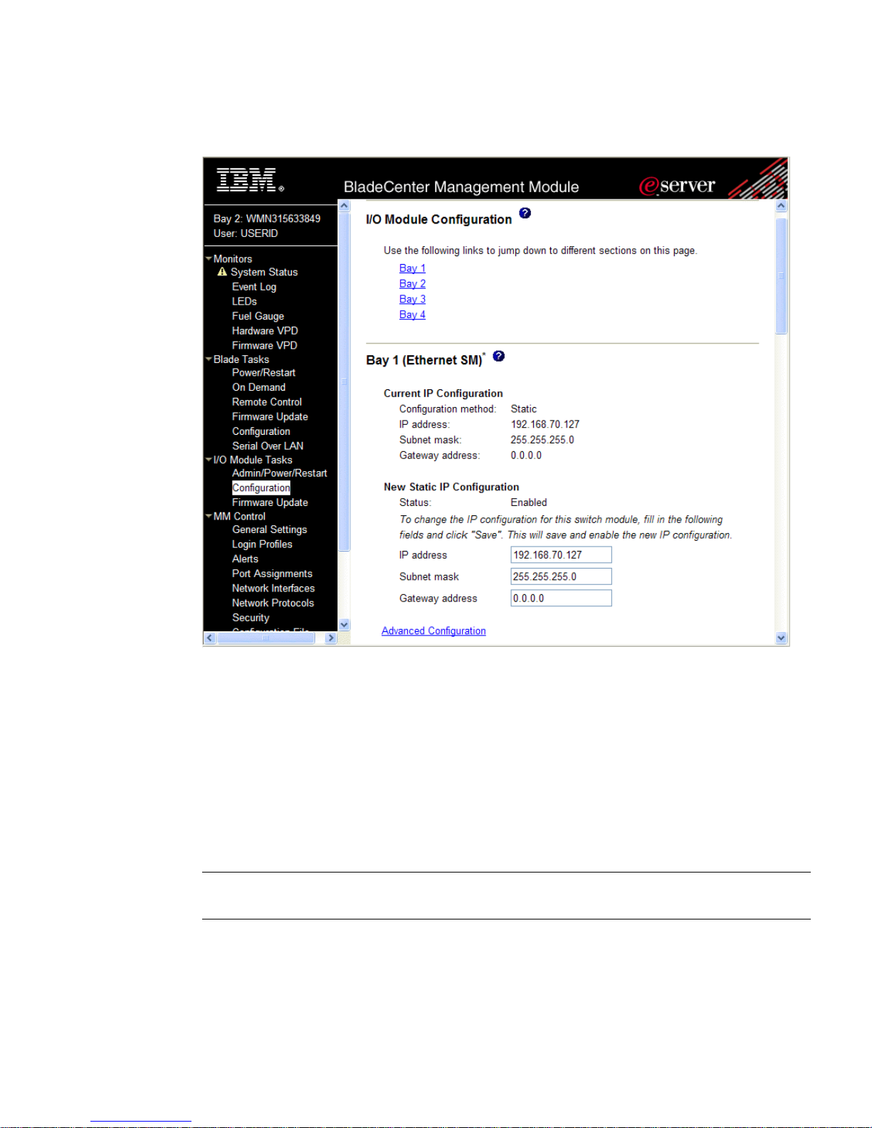
3. Select Configuration on the I/O Module Tasks menu on the left side of the BladeCenter
Management Module window. See Figure 1-1.
The Command Line Interface
21BMD00007, November 2007
Page 22
Alteon OS Command Reference
Figure 1-1 Switch management on the BladeCenter management module
4. You can use the default IP addresses provided by the management module, or you can
assign a new IP address to the switch module through the management module. You can
assign this IP address through one of the following methods:
Manually through the BladeCenter management module
Automatically through the IBM Director Configuration Wizard (available in
Director release 4.21)
NOTE – If you change the IP address of the GbE Switch Module, make sure that the switch
module and the management module both reside on the same subnet.
The Command Line Interface BMD00007, November 2007
22
Page 23

Alteon OS Command Reference
5. Enable the following features in the management module:
External Ports (I/O Module Tasks > Admin/Power/Restart > Advance Setup)
External management over all ports (Configuration > Advanced Configuration)
This setting is required if you want to access the management network through the external ports on the GbE Switch Module.
The default value is Disabled for both features. If these features are not already enabled,
change the value to Enabled, then Save.
NOTE – In Advanced Configuration > Advanced Setup, enable “Preserve new IP configura-
tion on all switch resets,” to retain the switch’s IP interface when you restore factory defaults.
This setting preserves the management port’s IP address in the management module’s memory,
so you maintain connectivity to the management module after a reset.
You can now start a Telnet session, Browser-Based Interface (Web) session, a Secure Shell session, or a secure HTTPS session to the GbE Switch Module.
Connecting to the Switch via Telnet
Use the management module to access the GbE Switch Module through Telnet. Choose
I/O Module Tasks > Configuration from the navigation pane on the left. Select a bay number
and click Advanced Configuration > Start Telnet/Web Session > Start Telnet Session. A
Telnet window opens a connection to the Switch Module (requires Java 1.4 Plug-in).
Once that you have configured the GbE Switch Module with an IP address and gateway, you
can access the switch from any workstation connected to the management network. Telnet
access provides the same options for user and administrator access as those available through
the management module, minus certain Telnet and management commands.
To establish a Telnet connection with the switch, run the Telnet program on your workstation
and issue the Telnet command, followed by the switch IP address:
telnet <switch IP address>
Running Telnet
Once the IP parameters on the GbE Switch Module are configured, you can access the CLI using
a T elnet connection. From the management module, you can establish a T elnet connection with
the switch.
You will then be prompted to enter a password as explained on page 26.
The Command Line Interface
23BMD00007, November 2007
Page 24

Alteon OS Command Reference
Establishing an SSH Connection
Although a remote network administrator can manage the configuration of a GbE Switch Module
via T elnet, this method does not provide a secure connection. The SSH (Secure Shell) protocol
enables you to securely log into another computer over a network to execute commands
remotely . As a secure alternative to us ing Telnet to manage switch configuration, SSH ensures
that all data sent over the network is encrypted and secure.
The switch can do only one session of key/cipher generation at a time. Thus, a SSH/SCP client
will not be able to login if the switch is doing key generation at that time or if another client
has just logged in before this client. Similarly, the system will fail to do the key generation if a
SSH/SCP client is logging in at that time.
The supported SSH encryption and authentication methods are listed below.
Server Host Authentication: Client RSA-authenticates the switch in the beginning of
every connection.
Key Exchange: RSA
Encryption: 3DES-CBC, DES
User Authentication: Local password authentication, Radius
The following SSH clients have been tested:
SSH 1.2.23 and SSH 1.2.27 for Linux (freeware)
SecureCRT 3.0.2 and SecureCRT 3.0.3 (Van Dyke Technologies, Inc.)
F-Secure SSH 1.1 for Windows (Data Fellows)
NOTE – The Alteon OS implementation of SSH is based on SSH version 1.5 and supports SSH-
1.5-1.X.XX. SSH clients of other versions (especially Version 2) are not supported.
The Command Line Interface BMD00007, November 2007
24
Page 25

Alteon OS Command Reference
Running SSH
Once the IP parameters are configured and the SSH service is turned on the GbE Switch Module,
you can access the command line interface using an SSH connection. The default setting for
SSH access is disabled.
To establish an SSH connection with the switch, run the SSH program on your workstation by
issuing the SSH command, followed by the switch IP address:
>> # ssh <switch IP address>
If SecurID authentication is required, use the following command:
>> # ssh -1 ace <switch IP address>
You will then be prompted to enter your user name and password.
The Command Line Interface
25BMD00007, November 2007
Page 26

Alteon OS Command Reference
Accessing the Switch
To enable bet ter swit ch management and user accountability, three levels or classes of user
access have been implemented on the
agement functions, and screens increase as needed to perform various switch management
tasks. Conceptually , access classes are defined as follows:
User interaction with the switch is completely passive—nothing can be changed on the
GbE Switch Module. Users may display information that has no security or privacy implica-
tions, such as switch statistics and current operational state information.
GbE Switch Module. Levels of access to CLI, Web man-
Operators can make temporary changes on the
GbE Switch Module. These changes are lost
when the switch is rebooted/reset. Operators have access to the switch management features used for daily switch operations. Because any changes an operator makes are undone
by a reset of the switch, operators cannot severely impact switch operation.
Administrators are the only ones that may make permanent changes to the switch configu-
ration—changes that are persistent across a reboot/reset of the switch. Administrators can
access switch functions to configure and troubleshoot problems on the
GbE Switch Module.
Because administrators can also make temporary (operator-level) changes as well, they
must be aware of the interactions between temporary and permanent changes.
Access to switch functions is controlled through the use of unique surnames and passwords.
Once you are connected to the switch via local Telnet, remote Telnet, or SSH, you are
prompted to enter a password. The default user names/password for each access level are listed
in the following table.
NOTE – It is recommended that you change default switch passwords after initial configuration
and as regularly as required under your network security po licies. For more information, see
“Setting Passwords” on page 43.
Table 1-2 User Access Levels
User Account Description and Tasks Performed Password
User The User has no direct responsibility for switch management.
Operator The Operator manages all functions of the switch. The
The Command Line Interface BMD00007, November 2007
26
user
He or she can view all switch status information and statistic s,
but cannot make any configuration changes to the switch.
oper
Operator can reset ports, except the management port.
Page 27

Alteon OS Command Reference
Table 1-2 User Access Levels
User Account Description and Tasks Performed Password
Administrator
The superuser Administrator has complete access to al l menus,
information, and configuration commands on the GbE Switch
Module, including the ability to change both the user and
administrator passwords.
admin
NOTE – With the exception of the “admin” user, access to each user level can be disabled by
setting the password to an empty value.
The Command Line Interface
27BMD00007, November 2007
Page 28

Alteon OS Command Reference
Setup Versus CLI
Once the administrator password is verified, you are given complete access to the switch. If the
switch is still set to its factory default configuration, the system will ask whethe r you wish to
run Setup (see Chapter 2, “First-Time Configuration”), a utility designed to help you through
the first-time configuration process. If the switch has already been configured, the Main Menu
of the CLI is displayed instead.
The following table shows the Main Menu with administrator privileges.
[Main Menu]
info - Information Menu
stats - Statistics Menu
cfg - Configuration Menu
oper - Operations Command Menu
boot - Boot Options Menu
maint - Maintenance Menu
diff - Show pending config changes [global command]
apply - Apply pending config changes [global command]
save - Save updated config to FLASH [global command]
revert - Revert pending or applied changes [global command]
exit - Exit [global command, always available]
NOTE – If you are accessing a user account, some menu options will not be available.
The Command Line Interface BMD00007, November 2007
28
Page 29

Alteon OS Command Reference
Command Line History and Editing
For a description of global commands, shortcuts, and command line editing functions, see
“Menu Basics” on page 47.”
Idle Timeout
By default, the switch will disconnect your Telnet session after five minutes of inactivity. This
function is controlled by the idle timeo ut par ameter, which can be set from 1 to 60 minutes. For
information on changing this par ameter, see “System Configuration” on page 179.
The Command Line Interface
29BMD00007, November 2007
Page 30

Alteon OS Command Reference
The Command Line Interface BMD00007, November 2007
30
Page 31

CHAPTER 2
First-Time Configuration
To help with the initial process of configuring your switch, the Alteon OS software includes a
Setup utility. The Setup utility prompts you step-by-step to enter all the necessary information
for basic configuration of the switch. This chapter describes how to use the Setup utility and
how to change system passwords. Before you run Setup, you must first connect to the switch
(see Chapter 1, “Connecting to the Switch”).
BMD00007, November 2007 31
Page 32

Alteon OS Command Reference
Using the Setup Utility
Whenever you log in as the system administrator under the factory default configuration, you
are asked whether you wish to run the Setup utility. Setup can also be activated manually from
the command line interface any time after login.
Information Needed For Setup
Setup requests the following information:
Basic system information
Date & time
Whether to use Spanning Tree Group or not
Optional configuration for each port
Speed, duplex, flow control, and negotiation mode (as appropriate)
Whether to use VLAN tagging or not (as appropriate)
Optional configuration for each VLAN
Name of VLAN
Which ports are included in the VLAN
Optional configuration of IP parameters
IP address, subnet mask, and VLAN for each IP interface
IP addresses for default gateway
Destination, subnet mask, and gateway IP address for each IP static route
Whether IP forwarding is enabled or not
Whether the RIP supply is enabled or not
First-Time Configuration BMD00007, November 2007
32
Page 33

Alteon OS Command Reference
Starting Setup When You Log In
The Setup prompt appears automatically whenever you login as the system administrator under
the factory default settings.
1. Connect to the switch.
After connecting, the login prompt will appear as shown below.
Enter Password:
2. Enter admin as the default administrator password.
If the factory default configuration is detected, the system prompts:
10Gb Uplink Ethernet Switch Module
18:44:05 Wed Jan 3, 2007
The switch is booted with factory default configuration.
To ease the configuration of the switch, a "Set Up" facility which
will prompt you with those configuration items that are essen tial to
the operation of the switch is provided.
Would you like to run "Set Up" to configure the switch? [y/n]:
NOTE – If the default admin login is unsuccessful, or if the administrator Main Menu appears
instead, the system configuration has probably been changed from the factory default settings.
If you are certain that you need to return the switch to its factory default settings, see “Select-
ing a Configuration Block” on page 346.
3. Enter
y to begin the initial configuration of the switch, or n to bypass the Setup facility.
First-Time Configuration
33BMD00007, November 2007
Page 34

Alteon OS Command Reference
Stopping and Restarting Setup Manually
Stopping Setup
To abort the Setup utili ty, press <Ctrl-C> during any Setup question. When you abort Setup,
the system will prompt:
Would you like to run from top again? [y/n]
Enter n to abort Setup, or y to restart the Setup program at the beginning.
Restarting Setup
You can restart the Setup utility manually at any time by entering the following command at
the administrator prompt:
# /cfg/setup
Setup Part 1: Basic System Configuration
When Setup is started, the system prompts:
"Set Up" will walk you through the configuration of
System Date and Time, Spanning Tree, Port Speed/Mode,
VLANs, and IP interfaces. [type Ctrl-C to abort "Set Up"]
------------------------------------------------------------
Will you be configuring VLANs? [y/n]
1. Enter
If you decide not to configure VLANs during this session, you can configure them later using
the configuration menus, or by restarting the Setup facility. For more information on configuring VLANs, see the Alteon OS 1.4 Application Guide.
Next, the Setup utility prompts you to input basic system information.
2. Enter the year of the current date at the prompt:
Enter the last two digits of the year as a number from 00 to 99. “00” is considered 2000. To
keep the current year, press <Enter>.
y if you will be configuring VLANs. Otherwise enter n.
Enter year [2007]:
First-Time Configuration BMD00007, November 2007
34
Page 35

Alteon OS Command Reference
NOTE – When the GbE Switch Module is reset, the date and time to revert to default values.
Use /cfg/sys/date and /cfg/sys/time to re-enter the current date and time.
The system displays the date and time settings:
System clock set to 18:55:36 Wed Jan 3, 2007.
3. Enter the month of the current system date at the prompt:
System Date:
Enter month [1]:
Enter the month as a number from 1 to 12. To keep the current month, press <Enter>.
4. Enter the day of the current date at the pr ompt :
Enter day [3]:
Enter the date as a number from 1 to 31. To keep the current day, press <Enter>.
5. Enter the hour of the current system time at the prompt:
System Time:
Enter hour in 24-hour format [18]:
Enter the hour as a number from 00 to 23. To keep the current hour, press <Enter>.
6. Enter the minute of the current time at the prompt:
Enter minutes [55]:
Enter the minute as a number from 00 to 59. To keep the current minute, press <Enter>.
7. Enter the seconds of the current time at the pr ompt:
Enter seconds [37]:
Enter the seconds as a number from 00 to 59. To keep the current second, press <Enter>.
The system displays the date and time settings:
System clock set to 8:55:36 Wed Jan 3, 2007.
First-Time Configuration
35BMD00007, November 2007
Page 36

Alteon OS Command Reference
8. Turn Spanning Tree Protocol on or off at the prompt:
Spanning Tree:
Current Spanning Tree Group 1 setting: ON
Turn Spanning Tree Group 1 OFF? [y/n]
Enter
y to turn off Spanning Tree, or enter n to leave Spanning Tree on.
Setup Part 2: Port Configuration
NOTE – When configuring port options for your switch, some of the prompts and options may
be different.
1. Select the port to configure, or skip port configuration at the prompt:
Port Config:
Enter port (INT1-14, MGT, EXT1-4):
NOTE – The sample screens that appear in this document might differ slightly from the screens
displayed by your system. Screen content varies based on the type of BladeCenter unit that you
are using and the firmware versions and options that are installed.
If you wish to change settings for individual ports, enter the number of the port you wish to
configure. To skip port configuration, press <Enter> without specifying any port and go to
“Setup Part 3: VLANs” on page 38.
2. Configure Gigabit Ethernet port flow parameters.
If you selected a port that has a Gigabit Ethernet connector, the system prompts:
Gig Link Configuration:
Port Flow Control:
Current Port EXT1 flow control setting: both
Enter new value ["rx"/"tx"/"both"/"none"]:
Enter
rx to enable receive flow control, tx for transmit flow control, both to enable both, or
none to turn flow control off for the port. To keep the current setting, press <Enter>.
First-Time Configuration BMD00007, November 2007
36
Page 37

Alteon OS Command Reference
3. Configure Gigabit Ethernet port autonegotiation mode.
If you selected a port that has a Gigabit Ethernet connector, the system prompts:
Port Auto Negotiation:
Current Port EXT1 autonegotiation: on
Enter new value ["on"/"off"]:
Enter on to enable port autonegotiation, off to disable it, or press <Enter> to keep the current
setting.
4. If configuring VLANs, enable or disable VLAN tagging for the port.
If you have selected to configure VLANs back in Part 1, the system prompts:
Port VLAN tagging config (tagged port can be a member of multiple VLANs)
Current TAG support: disabled
Enter new TAG support [d/e]:
Enter
d to disable VLAN tagging for the port or enter e to enable VLAN tagging for the port.
To keep the current setting, press <Enter>.
5. The system prompts you to configure the next port:
Enter port (INT1-14, MGT, EXT1-4):
When you are through configuring ports, press <Enter> without specifying any port. Otherwise, repeat the steps in this section.
First-Time Configuration
37BMD00007, November 2007
Page 38

Alteon OS Command Reference
Setup Part 3: VLANs
If you chose to skip VLANs configuration back in Part 1, skip to “Setup Part 4: IP Configura-
tion” on page 39.
1. Select the VLAN to configure, or skip VLAN configuration at the prompt:
VLAN Config:
Enter VLAN number from 2 to 4094, NULL at end:
If you wish to change settings for individual VLANs, enter the number of the VLAN you wish
to configure. T o skip VLAN configuration, press <Enter> without typing a VLAN number and
go to “Setup Part 4: IP Configuration” on page 39.
2. Enter the new VLAN name at the prompt:
Current VLAN name: VLAN 2
Enter new VLAN name:
Entering a new VLAN name is optional. To use the pending new VLAN name, press <Enter>.
3. Enter the VLAN port numbers:
Define Ports in VLAN:
Current VLAN 2: empty
Enter ports one per line, NULL at end:
Enter each port, by port number or port alias, and confirm placement of the port into this
VLAN. When you are finished adding ports to this VLAN, press <Enter> without specifying
any port.
4. Configure Spanning Tree Group membership for the VLAN:
Spanning Tree Group membership:
Current Spanning Tree Group index: 1
Enter new Spanning Tree Group index [1-127]:
5. The system prompts you to configure the next VLAN:
VLAN Config:
Enter VLAN number from 2 to 4094, NULL at end:
First-Time Configuration BMD00007, November 2007
38
Page 39

Alteon OS Command Reference
Repeat the steps in this section until all VLANs have been configured. When all VLANs have
been configured, press <Enter> without specifying any VLAN.
Setup Part 4: IP Configuration
The system prompts for IP parameters.
IP Interfaces
IP interfaces are used for defining subnets to which the switch belongs.
Up to 128 IP interfaces can be configured on the
GbE Switch Module. The IP address assigned to
each IP interface provide the switch with an IP presence on your network. No two IP interfaces
can be on the same IP subnet. The interfaces can be used for connecting to the switch for
remote configuration, and for routing between subnets and VLANs (if used).
1. Select the IP interface to configure, or skip interfac e configuration at the prompt:
IP Config:
IP interfaces:
Enter interface number: (1-128)
If you wish to configure individual IP interfaces, enter the number of the IP interface you with
to configure. To skip IP interface configuration, press <Enter> without typing an interface
number and go to “Default Gateways” on page 40.
NOTE – Interface 128 is reserved for switch management. If you change the IP address of IF
128, you can lose the connection to the management module. Use the management module to
change the IP address of the GbE Switch Module.
2. For the specified IP interface, enter the IP address in dotted decimal notation:
Current IP address: 0.0.0.0
Enter new IP address:
To keep the current setting, press <Enter>.
3. At the prompt, enter the IP subnet mask in dotted decimal notation:
Current subnet mask: 0.0.0.0
Enter new subnet mask:
First-Time Configuration
39BMD00007, November 2007
Page 40

Alteon OS Command Reference
To keep the current setting, press <Enter>.
4. If configuring VLANs, specify a VLAN for the interface.
This prompt appears if you selected to configure VLANs back in Part 1:
Current VLAN: 1
Enter new VLAN [1-4094]:
Enter the number for the VLAN to which the interface belongs, or press <Enter> without specifying a VLAN number to accept the current setting.
5. At the prompt, enter y to enable the IP interface, or n to leave it disabled:
Enable IP interface? [y/n]
6. The system prompts you to configure another interface:
Enter interface number: (1-128)
Repeat the steps in this section until all IP interfaces have been configured. When all interfaces
have been configured, press <Enter> without specifying any interface number.
Default Gateways
1. At the prompt, select a default gateway for configuration, or skip default gateway config-
uration:
IP default gateways:
Enter default gateway number: (1-4)
Enter the number for the default gateway to be configured. To skip default gateway configuration, press <Enter> without typing a gateway number and go to “IP Routing” on page 41.
2. At the prompt, enter the IP address for the selected default gateway:
Current IP address: 0.0.0.0
Enter new IP address:
Enter the IP address in dotted decimal notation, or press <Enter> without specifying an address
to accept the current setting.
First-Time Configuration BMD00007, November 2007
40
Page 41

Alteon OS Command Reference
3. At the prompt, enter y to enable the default gateway, or n to leave it disabl ed:
Enable default gateway? [y/n]
4. The system prompts you to configure another default gateway:
Enter default gateway number: (1-4)
Repeat the steps in this section until all default gateways have been configured. When all
default gateways have been configured, press <Enter> without specifying any number.
IP Routing
When IP interfaces are configured for the various subnets attached to your switch, IP routing
between them can be performed entirely within the switch. This eliminates the need to send
inter-subnet communication to an external router device. Routing on more complex networks,
where subnets may not have a direct presence on the
through configuring static routes or by letting the switch learn routes dynamically.
GbE Switch Module, can be accomplished
This part of the Setup program prompts you to configure the various routing parameters.
1. At the prompt, enable or disable forwarding for IP Routing:
Enable IP forwarding? [y/n]
Enter
y to enable IP forwarding. To disable IP forwarding, enter n.To keep the current setting,
press <Enter>.
Setup Part 5: Final Steps
1. When prompted, decide whether to restart Setup or continu e :
Would you like to run from top again? [y/n]
Enter y to restart the Setup utility from the beginning, or n to continue.
2. When prompted, decide whether you wish to review the configuration changes:
Review the changes made? [y/n]
Enter
y to review the changes made during this session of the Setup utility . Enter n to continue
without reviewing the changes. We recommend that you review the changes.
First-Time Configuration
41BMD00007, November 2007
Page 42

Alteon OS Command Reference
3. Next, decide whether to apply the changes at the prompt:
Apply the changes? [y/n]
y to apply the changes, or n to continue without applying. Changes are normally applied.
Enter
4. At the prompt, decide whether to make the changes permanent:
Save changes to flash? [y/n]
Enter
y to save the changes to flash. Enter n to continue without saving the changes. Changes
are normally saved at this point.
5. If you do not apply or save the changes, the system prompts whether to abort them:
Abort all changes? [y/n]
Enter
y to discard the changes. Enter n to return to the “Apply the changes?” prompt.
NOTE – After initial configuration is complete, it is recommended that you change the defaul t
passwords as shown in “Setting Passwords” on page 43.
Optional Setup for Telnet Support
NOTE – This step is optional. Perform this procedure only if you are planning on connecting to
the GbE Switch Module through a remote Telnet connection.
1. Telnet is enabled by default. To change the setting, use the following command:
>> # /cfg/sys/access/tnet
2. Apply and save SNMP and /or telnet configuration(s).
>> System# apply
>> System# save
First-Time Configuration BMD00007, November 2007
42
Page 43

Alteon OS Command Reference
Setting Passwords
It is recommended that you change the user and administrator passwords after initial configuration and as regularly as required under your network security policies.
To chang e the admi nistrator password, you must login using the administrator password.
NOTE – If you forget your administrator password, call your technical support representative
for help using the password fix-up mode.
Changing the Default Administrator Password
The administrator has complete access to all menus, information, and configuration commands, including the ability to change both the user and administrator passwords.
The default password for the administrator account is admin. T o change the default password,
follow this procedure:
1. Connect to the switch and log in using the admin password.
2. From the Main Menu, use the following command to access the Configuration Menu:
Main# /cfg
The Configuration Menu is displayed.
[Configuration Menu]
sys - System-wide Parameter Menu
port - Port Menu
pmirr - Port Mirroring Menu
l2 - Layer 2 Menu
l3 - Layer 3 Menu
qos - QOS Menu
acl - Access Control List Menu
setup - Step by step configuration set up
dump - Dump current configuration to script file
ptcfg - Backup current configuration to FTP/TFTP server
gtcfg - Restore current configuration from FTP/TFTP server
cur - Display current configuration
3. From the Configuration Menu, use the following command to select the System Menu:
>> Configuration# sys
First-Time Configuration
43BMD00007, November 2007
Page 44

Alteon OS Command Reference
The System Menu is displayed.
[System Menu]
syslog - Syslog Menu
sshd - SSH Server Menu
radius - RADIUS Authentication Menu
tacacs+ - TACACS+ Authentication Menu
ldap - LDAP Authentication Menu
ntp - NTP Server Menu
ssnmp - System SNMP Menu
access - System Access Menu
date - Set system date
time - Set system time
timezone - Set system timezone (daylight savings)
olddst - Set system DST for US
dlight - Set system daylight savings
idle - Set timeout for idle CLI sessions
notice - Set login notice
bannr - Set login banner
hprompt - Enable/disable display hostname (sysName) in CLI prompt
reminder - Enable/disable Reminders
cur - Display current system-wide parameters
4. From the System Menu, use the following command to select the System Access Menu:
>> System# access
The System Access Menu is displayed.
[System Access Menu]
mgmt - Management Network Definition Menu
user - User Access Control Menu (passwords)
http - Enable/disable HTTP (Web) access
https - HTTPS Web Access Menu
wport - Set HTTP (Web) server port number
snmp - Set SNMP access control
userbbi - Enable/disable user configuration from BBI
tsbbi - Enable/disable telnet/ssh configuration from BBI
tnet - Enable/disable Telnet access
tnport - Set Telnet server port number
tport - Set the TFTP Port for the system
cur - Display current system access configuration
First-Time Configuration BMD00007, November 2007
44
Page 45

Alteon OS Command Reference
5. Select the administrator password.
System Access# user/admpw
6. Enter the current administrator password at the prompt:
Changing ADMINISTRATOR password; validation required...
Enter current administrator password:
NOTE – If you forget your administrator password, call your technical support representative
for help using the password fix-up mode.
7. Enter the new administrator password at the prompt:
Enter new administrator password:
8. Enter the new administrator password, again, at the prompt:
Re-enter new administrator password:
9. Apply and save your change by entering the following commands:
System# apply
System# save
Changing the Default User Password
The user login has limited control of the switch. Through a user account, you can view switch
information and statistics, but you can’t make configuration changes.
The default password for the user account is user. This password can be changed from the
user account. The administrator can change all passwords, as shown in the following procedure.
1. Connect to the switch and log in using the admin password.
2. From the Main Menu, use the following command to access the Configuration Menu:
Main# cfg
First-Time Configuration
45BMD00007, November 2007
Page 46

Alteon OS Command Reference
3. From the Configuration Menu, use the following command to select the System Menu:
>> Configuration# sys
4. From the System Menu, use the following command to select the System Access Menu:
>> System# access
5. Select the user password.
System# user/usrpw
6. Enter the current administrator password at the prompt.
Only the administrator can change the user password. Entering the administrator password
confirms your authority.
Changing USER password; validation required...
Enter current administrator password:
7. Enter the new user password at the prompt:
Enter new user password:
8. Enter the new user password, again, at the prompt:
Re-enter new user password:
9. Apply and save your changes:
System# apply
System# save
First-Time Configuration BMD00007, November 2007
46
Page 47

CHAPTER 3
Menu Basics
The GbE Switch Module’s Command Line Interface (CLI) is used for viewing switch information and statistics. In addition, the administrator can use the CLI for performing all levels of
switch configuration.
To make the CLI easy to use, the various commands have been logically grouped into a series
of menus and sub-menus. Each menu displays a list of commands and/or sub-menus that are
available, along with a summary of what each command will do. Below each menu is a prompt
where you can enter any command appropriate to the current menu.
This chapter describes the Main Menu commands, and provides a list of commands and shortcuts that are commonly available from all the menus within the CLI.
BMD00007, November 2007 47
Page 48

Alteon OS Command Reference
The Main Menu
The Main Menu appears after a successful connection and login. The following table shows
the Main Menu for the administrator login. Some features are not available under the user
login.
[Main Menu]
info - Information Menu
stats - Statistics Menu
cfg - Configuration Menu
oper - Operations Command Menu
boot - Boot Options Menu
maint - Maintenance Menu
diff - Show pending config changes [global command]
apply - Apply pending config changes [global command]
save - Save updated config to FLASH [global command]
revert - Revert pending or applied changes [global command]
exit - Exit [global command, always available]
Menu Basics BMD00007, November 2007
48
Page 49

Alteon OS Command Reference
Menu Summary
Information Menu
Provides sub-menus for displaying information about the current status of the switch:
from basic system settings to VLANs, and more.
Statistics Menu
Provides sub-menus for displaying switch performance statistics. Included are port, IF, IP,
ICMP, TCP, UDP , SNMP, routing, ARP, DNS, and VRRP statistics.
Configuration Menu
This menu is available only from an administrator login. It includes sub-menus for configuring every aspect of the switch. Changes to configuration are not active until explicitly
applied. Changes can be saved to non-volatile memory.
Operations Command Menu
Operations-level commands are used for making immediate and temporary changes to
switch configuration. This menu is used for bringing ports temporarily in and out of service, performing port mirroring, and enabling or disabling Server Load Balancing functions. It is also used for activating or deactivating optional software packages.
Boot Options Menu
This menu is used for upgrading switch software, selecting configuration blocks, and for
resetting the switch when necessary.
Maintenance Menu
This menu is used for debugging purposes, enabling you to generate a dump of the critical
state information in the switch, and to clear entries in the forwarding database and the
ARP and routing tables.
Menu Basics
49BMD00007, November 2007
Page 50

Alteon OS Command Reference
Global Commands
Some basic commands are recognized throughout the menu hierarchy. These commands are
useful for obtaining online help, navigating through menus, and for applying and saving configuration changes.
For help on a specific command, type help. You will see the following screen:
Global Commands: [can be issued from any menu]
help up print pwd
lines verbose exit quit
diff apply save revert
revert apply
ping traceroute telnet history
pushd popd who chpass_p
chpass_s
The following are used to navigate the menu structure:
. Print current menu
.. Move up one menu level
/ Top menu if first, or command separator
! Execute command from history
Table 3-1 Description of Global Commands
Command Action
? command
or help
. or print Display the current menu.
.. or up Go up one level in the menu structure.
/ If placed at the beginning of a command, go to the Main Menu. Otherwise,
lines Set the number of lines (n) that display on the screen at one time. T he default
diff Show any pending configuration changes.
apply Apply pending configuration changes.
save Write configuration changes to non-volatile flash memory.
Provides more information about a specific command on the current menu.
When used without the command parameter, a summary of the global commands is displayed.
this is used to separate multiple commands placed on the sam e line .
is 24 lines. When used without a value, the current setting is displayed. Set
lines to a value of 0 (zero) to disable pagination.
Menu Basics BMD00007, November 2007
50
Page 51

Alteon OS Command Reference
Table 3-1 Description of Global Commands
Command Action
revert Remove pending configuration changes between “apply” commands. Use
this command to restore configuration parameters set since last apply.
revert apply Remove pending or applied configuration changes between “save” com-
mands. Use this command to remove any configuration changes made since
last save.
exit or quit Exit from the command line interface and log out.
ping Use this command to verify station-to-station connectivity across the net-
work. The format is as follows:
ping <host name>|<IP address> [tries (1-32)> [msec delay]]
Where IP address is the hostname or IP address of the device, tries (optional)
is the number of attempts (1-32), msec delay (optional) is the number of milliseconds between attempts. The DNS parameters must be configured if
specifying hostnames (see “Domain Name System Configuration” on page
297).
traceroute Use this command to identify the route used for station-to-station connectiv-
ity across the network. The format is as follows:
traceroute <host name>| <IP address> [<max-hops (1-32)>
[msec delay]]
Where IP address is the hostname or IP address of the target station, maxhops (optional) is the maximum distance to trace (1-16 devices), and delay
(optional) is the number of milliseconds for wait for the response. As with
ping, the DNS parameters must be configured if specifying hostnames.
pwd Display the command path used to reach the current menu.
verbose n Sets the level of information displayed on the screen:
0 =Quiet: Nothing appears except errors—not even prompts.
1 =Normal: Prompts and requested output are shown, but no menus.
2 =Verbose: Everything is shown.
When used without a value, the current setting is displayed.
telnet This command is used to telnet out of the switch. The format is as follows:
telnet <hostname>|<IP address>
[port]
Where IP address is the hostname or IP address of the device.
history This command displays the most recent commands.
pushd Save the current menu path, so you can jump back to it using popd.
popd Go to the menu path and position previously saved by using pushd.
who Displays a list of users that are logged on to the switch.
chpass_p Configures the password for the primary TACACS+ server.
Menu Basics
51BMD00007, November 2007
Page 52

Alteon OS Command Reference
Table 3-1 Description of Global Commands
Command Action
chpass_s Configures the password for the secondary TACACS+ server.
Menu Basics BMD00007, November 2007
52
Page 53

Alteon OS Command Reference
Command Line History and Editing
Using the command line interface, you can retrieve and modify previously entered commands
with just a few keystrokes. The following options are available globally at the command line:
Table 3-2 Command Line History and Editing Options
Option Description
history Display a numbered list of the last 64 previously entered commands.
!! Repeat the last entered command.
!n
<Ctrl-p> (Also the up arrow key.) Recall the previous command from the history list. This can
<Ctrl-n> (Also the down arrow key .) Recall the next command from the history list. This can be
<Ctrl-a> Move the cursor to the beginning of command line.
<Ctrl-e> Move cursor to the end of the command line.
<Ctrl-b> (Also the left arrow key.) Move the cursor back one position to the left.
<Ctrl-f> (Also the right arrow key.) Move the cursor forward one position to the right.
<Backspace> (Also the Delete key.) Erase one character to the left of the cursor position.
<Ctrl-d> Delete one character at the cursor position.
<Ctrl-k> Kill (erase) all characters from the cursor position to the end of the command line.
<Ctrl-l> Redraw the screen.
<Ctrl-u> Clear the entire line.
Repeat the nth command shown on the history list.
be used multiple times to work backward through the last 64 commands. The recalled
command can be entered as is, or edited using the options below.
used multiple times to work forward through the last 64 commands. The recalled command can be entered as is, or edited using the options below.
Other keys Insert new characters at the cursor position.
Menu Basics
53BMD00007, November 2007
Page 54

Alteon OS Command Reference
Command Line Interface Shortcuts
Command Stacking
As a shortcut, you can type multiple commands on a single line, separated by forward
slashes (/). You can connect as many commands as required to access the menu option that
you want. For example, the keyboard shortcut to access the Spanning Tree Port Configuration
Menu from the Main# prompt is as follows:
Main# cfg/l2/stg 1/port
Command Abbreviation
Most commands can be abbreviated by entering the first characters which distinguish the command from the others in the same menu or sub-menu. For example, the command shown above
could also be entered as follows:
Main# c/l2/stg 1/po
Tab Completion
By entering the first letter of a command at any menu prompt and hitting <Tab>, the CLI will
display all commands or options in that menu that begin with that letter. Entering additional
letters will further refine the list of commands or options displayed. If only one command fits
the input text when <Tab> is pressed, that command will be supplied on the command line,
waiting to be entered. If the <Tab> key is pressed without any input on the command line, the
currently active menu will be displayed.
Menu Basics BMD00007, November 2007
54
Page 55

CHAPTER 4
The Information Menu
You can view configuration information for the switch in both the user and administrator command
modes. This chapter discusses how to use the command line interface to display switch infor-
mation.
BMD00007, November 2007 55
Page 56

Alteon OS Command Reference
/info
Information Menu
[Information Menu]
sys - System Information Menu
l2 - Layer 2 Information Menu
l3 - Layer 3 Information Menu
qos - QoS Menu
acl - Show ACL information
link - Show link status
port - Show port information
transcvr - Show Port Transceiver status
dump - Dump all information
The information provided by each menu option is briefly described in Table 4-1, with pointers
to detailed information.
Table 4-1 Information Menu Options (/info)
Command Syntax and Usage
sys
Displays the System Information Menu. For details, see page 58.
l2
Displays the Layer 2 Information Menu. For details, see page 74.
l3
Displays the Layer 3 Information Menu. For details, see page 95.
qos
Displays the Quality of Service (QoS) Information Menu. For details, see page 117.
acl
Displays the current configuration profile for each Access Control List (ACL) and ACL Group.
For details, see page 119.
link
Displays configuration information about each port, including:
Port alias and number
Port speed
Duplex mode (half, full, or auto)
Flow control for transmit and receive (no or yes)
Link status (up, down or disabled)
For details, see page 120.
The Information Menu BMD00007, November 2007
56
Page 57

Alteon OS Command Reference
Table 4-1 Information Menu Options (/info)
Command Syntax and Usage
port
Displays port status information, including:
Port alias and number
Whether the port uses VLAN Tagging or not
Port Fast Fowarding status
FDB Learning status
Flooding of unknown destin ation MAC status
Port VLAN ID (PVID)
Port name
VLAN membership
For details, see page 121.
transcvr
Displays the status of the port transceiver module on each Fiber External Port.
For details, see page 123.
dump
Dumps all switch information available from the Information Menu (10K or more, depending on
your configuration).
If you want to capture dump data to a file, set your communication software on your workstation to
capture session data prior to issuing the dump commands.
The Information Menu
57BMD00007, November 2007
Page 58

Alteon OS Command Reference
/info/sys
System Information
[System Menu]
snmpv3 - SNMPv3 Information Menu
chassis - Show BladeCenter Chassis related information
general - Show general system information
log - Show last 100 syslog messages
user - Show current user status
dump - Dump all system information
The information provided by each menu option is briefly described in Table 4-2, with pointers
to where detailed information can be found.
Table 4-2 System Menu Options (/info/sys)
Command Syntax and Usage
snmpv3
Displays SNMPv3 Information Menu. To view the menu options, see page 59.
chassis
Displays information about the BladeCenter chassis. For details, see page 69.
general
Displays system information, including:
System date and time
Switch model name and number
Switch name and location
Time of last boot
MAC address of the switch management processor
IP address of the management interface
Hardware version and part number
Software image file and version number
Configuration name
Log-in banner, if one is configured
For details, see page 70.
log
Displays most recent syslog messages. For details, see page 72.
user
Displays configured user names and their status. For details, see page 73.
dump
Dumps all switch information available from the Information Menu (10K or more, depending on
your configuration).
The Information Menu BMD00007, November 2007
58
Page 59

Alteon OS Command Reference
/info/sys/snmpv3
SNMPv3 System Information Menu
SNMP version 3 (SNMPv3) is an extensible SNMP Framework that supplements the SNMPv2
Framework by supporting the following:
a new SNMP message format
security for messages
access control
remote configuration of SNMP parameters
For more details on the SNMPv3 architecture please refer to RFC2271 to RFC2276.
[SNMPv3 Information Menu]
usm - Show usmUser table information
view - Show vacmViewTreeFamily table information
access - Show vacmAccess table information
group - Show vacmSecurityToGroup table information
comm - Show community table information
taddr - Show targetAddr table information
tparam - Show targetParams table information
notify - Show notify table information
dump - Show all SNMPv3 information
Table 4-3 SNMPv3 information Menu Options (/info/sys/snmpv3)
Command Syntax and Usage
usm
Displays User Security Model (USM) table information. To view the table, see page 61.
view
Displays information about view , sub-trees, mask and type of view. To view a sample, see page 62.
access
Displays View-based Access Control information. To view a sample, see page 63.
group
Displays information about the group that includes, the security model, user name, and group
name. To view a sample, see page 64.
comm
Displays information about the community table information. To view a sample, see page 64.
taddr
Displays the Target Address table information. To view a sample, see page 65.
The Information Menu
59BMD00007, November 2007
Page 60

Alteon OS Command Reference
Table 4-3 SNMPv3 information Menu Options (/info/sys/snmpv3)
Command Syntax and Usage
tparam
Displays the Target parameters table information. To view a sample, see page 66.
notify
Displays the Notify table information. To view a sample, see page 67.
dump
Displays all the SNMPv3 information. To view a sample, see page 68.
The Information Menu BMD00007, November 2007
60
Page 61

Alteon OS Command Reference
/info/sys/snmpv3/usm
SNMPv3 USM User Table Information
The User-based Security Model (USM) in SNMPv3 provides security services such as authentication and privacy of messages. This security model makes use of a defined set of user identities displayed in the USM user table. The USM user table contains the following information:
the user name
a security name in the form of a string whose format is independent of the Security Model
an authentication protocol, which is an indication that the messages sent on behalf of the
user can be authenticated
the privacy protocol
usmUser Table:
User Name Protocol
-------------------------------- -------------------------------adminmd5 HMAC_MD5, DES PRIVACY
adminsha HMAC_SHA, DES PRIVACY
v1v2only NO AUTH, NO PRIVACY
Table 4-4 USM User Table Information Parameters (/info/sys/usm)
Field Description
User Name This is a string that represents the name of the user that you can
use to access the switch.
Protocol This indicates whether messages sent on behalf of this user are
protected from disclosure using a privacy protocol. Alteon OS
supports DES algorithm for privacy. The software also supports
two authentication algorithms: MD5 and HMAC-SHA.
The Information Menu
61BMD00007, November 2007
Page 62

Alteon OS Command Reference
/info/sys/snmpv3/view
SNMPv3 View Table Information
The user can control and restrict the access allowed to a group to only a subset of the management information in the management domain that the group can access within each context by
specifying the group’s rights in terms of a particular MIB view for security reasons.
View Name Subtree Mask Type
----------------- ------------------ -------------- -------iso 1.3 included
v1v2only 1.3 included
v1v2only 1.3.6.1.6.3.15 excluded
v1v2only 1.3.6.1.6.3.16 excluded
v1v2only 1.3.6.1.6.3.18 excluded
Table 4-5 SNMPv3 View Table Information Parameters (/info/sys/snmpv3/view)
Field Description
View Name Displays the name of the view.
Subtree Displays the MIB subtree as an OID string. A view subtree is the set
of all MIB object instances which have a common Object Identifier
prefix to their names.
Mask Displays the bit mask.
Type Displays whether a family of view subtrees is included or
excluded from the MIB view.
The Information Menu BMD00007, November 2007
62
Page 63

Alteon OS Command Reference
/info/sys/snmpv3/access
SNMPv3 Access Table Information
The access control sub system provides authorization services.
The vacmAccessTable maps a group name, security information, a context, and a message
type, which could be the read or write type of operation or notification into a MIB view.
The V iew-based Access Control Model defines a set of services that an application can use for
checking access rights of a group. This group's access rights are determined by a read-view, a
write-view and a notify-view. The read-view represents the set of object instances authorized
for the group while reading the objects. The write-view represents the set of object instances
authorized for the group when writing objects. The notify-view represents the set of object
instances authorized for the group when sending a notification.
Group Name Prefix Model Level Match ReadV WriteV NotifyV
---------- ------ ------- ------ ------ ------ ------ ----v1v2grp snmpv1 noAuthNoPriv exact iso iso v1v2only
admingrp usm authPriv exact iso iso iso
Table 4-6 SNMPv3 Access Table Information (/info/sys/snmpv3/access)
Field Description
Group Name Displays the name of group.
Prefix Displays the prefix that is configured to match the values.
Model Displays the security model used, for example, SNMPv1, or
SNMPv2 or USM.
Level Displays the minimum level of security required to gain rights of
access. For example, noAuthNoPriv, authNoPriv, or auth-
Priv.
Match Displays the match for the contextName. The options are: exact
and prefix.
ReadV Displays the MIB view to which this entry authorizes the read
access.
WriteV Displays the MIB view to which this entry authorizes the write
access.
NotifyV Displays the Notify view to which this entry authorizes the notify
access.
The Information Menu
63BMD00007, November 2007
Page 64

Alteon OS Command Reference
/info/sys/snmpv3/group
SNMPv3 Group Table Information
A group is a combination of security model and security name that defines the access rights
assigned to all the security names belonging to that group. The group is identified by a group
name.
Sec Model User Name Group Name
---------- ------------------------------- -------------------snmpv1 v1v2only v1v2grp
usm adminmd5 admingrp
usm adminsha admingrp
Table 4-7
Field Description
Sec Model Displays the security model used, which is any one of: USM,
User Name Displays the name for the group.
Group Name Displays the access name of the group.
SNMPv3 Group Table Information Parameters (/info/sys/snmpv3/group)
SNMPv1, SNMPv2, and SNMPv3.
/info/sys/snmpv3/comm
SNMPv3 Community Table Information
This command displays the community table information stored in the SNMP engine.
Index Name User Name Tag
---------- ---------- -------------------- ---------trap1 public v1v2only v1v2trap
Table 4-8 SNMPv3 Community Table Parameters (/info/sys/snmpv3/comm)
Field Description
Index Displays the unique index value of a row in this table
Name Displays the community string, which represents the configuration.
User Name Displays the User Security Model (USM) user name.
Tag
The Information Menu BMD00007, November 2007
64
Displays the community tag. This tag specifies a set of transport
endpoints from which a command responder application accepts
management requests and to which a command responder application sends an SNMP trap.
Page 65

Alteon OS Command Reference
/info/sys/snmpv3/taddr
SNMPv3 Target Address Table Information
This command displays the SNMPv3 target address table information, which is stored in the
SNMP engine.
Name Transport Addr Port Taglist Params
---------- --------------- ---- ---------- --------------trap1 47.81.25.66 162 v1v2trap v1v2param
Table 4-9 SNMPv3 Target Address Table Information Parameters (/info/sys/
snmpv3/taddr)
Field Description
Name Displays the locally arbitrary, but unique identifier associated with
this snmpTargetAddrEntry.
Transport Addr Displays the transport addresses.
Port Displays the SNMP UDP port number.
Taglist This column contains a list of tag values which a re used to select tar-
get addresses for a particular SNMP message.
Params The value of this object identifies an entry in the snmpTargetParam-
sT able. The identified entry contains SNMP parameters to be used
when generating messages to be sent to this transport address.
The Information Menu
65BMD00007, November 2007
Page 66

Alteon OS Command Reference
/info/sys/snmpv3/tparam
SNMPv3 Target Parameters Table Information
Name MP Model User Name Sec Model Sec Level
--------------- -------- -------------- --------- --------v1v2param snmpv2c v1v2only snmpv1 noAuthNoPriv
Table 4-10 SNMPv3 Target Parameters Table Information (/info/sys/snmpv3/
tparam)
Field Description
Name Displays the locally arbitrary, but unique identifier associated with
MP Model Displays the Message Processing Model used when generating
User Name Displays the securityName, which identifies the entry on whose
this snmpTargeParamsEntry.
SNMP messages using this entry .
behalf SNMP messages will be generated using this entry.
Sec Model Displays the security model used when generating SNMP messages
using this entry. The system may choose to return an inconsis-
tentValue error if an attempt is made to set this variable to a
value for a security model which the system does not support.
Sec Level Displays the level of security used when generating SNMP mes-
sages using this entry.
The Information Menu BMD00007, November 2007
66
Page 67

Alteon OS Command Reference
/info/sys/snmpv3/notify
SNMPv3 Notify Table Information
Name Tag
-------------------- -------------------v1v2trap v1v2trap
Table 4-11 SNMPv3 Notify Table Information (/info/sys/snmpv3/notify)
Field Description
Name The locally arbitrary , but unique identifier associated with this
snmpNotifyEntry.
Tag This represents a single tag value which is used to select entries in
the snmpTargetAddrTable. Any entry in the snmpTargetAddrTable that contains a tag value equal to the value of this
entry, is selected. If this entry contains a value of zero length, no
entries are selected.
The Information Menu
67BMD00007, November 2007
Page 68

Alteon OS Command Reference
/info/sys/snmpv3/dump
SNMPv3 Dump Information
usmUser Table:
User Name Protocol
-------------------------------- -------------------------------adminmd5 HMAC_MD5, DES PRIVACY
adminsha HMAC_SHA, DES PRIVACY
v1v2only NO AUTH, NO PRIVACY
vacmAccess Table:
Group Name Prefix Model Level Match ReadV WriteV NotifyV
---------- ------ ------- ---------- ------ ------- -------- -----v1v2grp snmpv1 noAuthNoPriv exact iso iso v1v2only
admingrp usm authPriv exact iso iso iso
vacmViewTreeFamily Table:
View Name Subtree Mask Type
-------------------- --------------- ------------ -------------iso 1.3 included
v1v2only 1.3 included
v1v2only 1.3.6.1.6.3.15 excluded
v1v2only 1.3.6.1.6.3.16 excluded
v1v2only 1.3.6.1.6.3.18 excluded
vacmSecurityToGroup Table:
Sec Model User Name Group Name
---------- ------------------------------- ----------------------snmpv1 v1v2only v1v2grp
usm adminsha admingrp
snmpCommunity Table:
Index Name User Name Tag
---------- ---------- -------------------- ---------snmpNotify Table:
Name Tag
-------------------- -------------------snmpTargetAddr Table:
Name Transport Addr Port Taglist Params
---------- --------------- ---- ---------- --------------snmpTargetParams Table:
Name MP Model User Name Sec Model Sec Level
-------------------- -------- ------------------ --------- -------
The Information Menu BMD00007, November 2007
68
Page 69

Alteon OS Command Reference
info/sys/chassis
BladeCenter Chassis Information
IBM BladeCenter Chassis Related Information:
Switch Module Bay = 1
Chassis Type = Enterprise
POST Results = 0xff
Management Module Control -
Default Configuration = FALSE
Skip Extended Memory Test = FALSE
Disable External Ports = FALSE
POST Diagnostics Control = Normal Diagnostics
Control Register = 0x19
Extended Control Register = 0x00
Management Module Status Reporting -
Device PowerUp Complete = TRUE
Over Current Fault = FALSE
Fault LED = OFF
Primary Temperature Warning = OK
Secondary Temperature Warning = OK
Status Register = 0x40
Extended Status Register = 0x01
Chassis information includes details about the BladeCenter chassis and management module
settings.
The Information Menu
69BMD00007, November 2007
Page 70

Alteon OS Command Reference
/info/sys/general
General System Information
System Information at 0:16:42 Wed Jan 3, 2007
Time zone: No timezone configured
Nortel 10Gb Uplink Ethernet Switch Module
Switch is up 5 days, 2 hours, 16 minutes and 42 seconds.
Last boot: 0:00:47 Wed Jan 3, 2007 (power cycle)
MAC address: 00:11:58:ad:a3:00 Management IP Address (if 128):
10.90.90.97
Software Version 1.2.0 (FLASH image1), factory default configuration.
PCBA Part Number: 317857-A
FAB Number: EL4512011
Serial Number: YJ1WDW47N277
Manufacturing Date:
Hardware Revision: 0
Board Revision: 0
PLD Firmware Version: 5.0
Temperature Sensor 1 (Warning): 42.5 C (Warn at 85.0 C/
Recover at 79.0 C)
Temperature Sensor 2 (Shutdown): 44.0 C (Warn at 93.0 C/
Recover at 86.0 C)
Temperature Sensor 3 (Exhaust): 42.5 C
Temperature Sensor 4 (Inlet): 42.5 C
Switch is in I/O Module Bay 0
NOTE – The display of temperature will come up only if the temperature of any of the sensors
exceeds the temperature threshold. There will be a warning from the software if any of the sensors exceeds this temperature threshold. The switch will shut down if the power supply overheats.
System information includes:
System date and time
Switch model
Switch name and location
Time of last boot
MAC address of the switch management processor
The Information Menu BMD00007, November 2007
70
Page 71

IP address of IP interface #1
Hardware version and part number
Software image file and version number
Configuration name
Log-in banner, if one is configured
Alteon OS Command Reference
The Information Menu
71BMD00007, November 2007
Page 72

Alteon OS Command Reference
/info/sys/log
Show Recent Syslog Messages
Date Time Criticality level Message
Jul 8 17:25:41 NOTICE system: link up on port INT1
Jul 8 17:25:41 NOTICE system: link up on port INT8
Jul 8 17:25:41 NOTICE system: link up on port INT7
Jul 8 17:25:41 NOTICE system: link up on port INT2
Jul 8 17:25:41 NOTICE system: link up on port INT1
Jul 8 17:25:41 NOTICE system: link up on port INT4
Jul 8 17:25:41 NOTICE system: link up on port INT3
Jul 8 17:25:41 NOTICE system: link up on port INT6
Jul 8 17:25:41 NOTICE system: link up on port INT5
Jul 8 17:25:41 NOTICE system: link up on port EXT4
Jul 8 17:25:41 NOTICE system: link up on port EXT1
Jul 8 17:25:41 NOTICE system: link up on port EXT3
Jul 8 17:25:41 NOTICE system: link up on port EXT2
Jul 8 17:25:41 NOTICE system: link up on port INT3
Jul 8 17:25:42 NOTICE system: link up on port INT2
Jul 8 17:25:42 NOTICE system: link up on port INT4
Jul 8 17:25:42 NOTICE system: link up on port INT3
Jul 8 17:25:42 NOTICE system: link up on port INT6
Jul 8 17:25:42 NOTICE system: link up on port INT5
Jul 8 17:25:42 NOTICE system: link up on port INT1
Jul 8 17:25:42 NOTICE system: link up on port INT6
Each syslog message has a criticality level associated with it, included in text form as a prefix
to the log message. One of eight different prefixes is used, depending on the condition that the
administrator is being notif i ed of, as shown below.
EMERG: indicates the system is unusable
ALERT: Indicates action should be taken immediately
CRIT: Indicates critical conditions
ERR: indicates error conditions or errored operations
WARNING: indicates warning conditions
NOTICE: indicates a normal but significant condition
INFO: indicates an information message
DEBUG: indicates a debug-level message
The Information Menu BMD00007, November 2007
72
Page 73

Alteon OS Command Reference
/info/sys/user
User Status
Usernames:
user - enabled - offline
oper - disabled - offline
admin - Always Enabled - online 1 session
Current User ID table:
1: name paul , dis, cos user , password valid, offline
Current strong password settings:
strong password status: disabled
This command displays the status of the configured usernames.
The Information Menu
73BMD00007, November 2007
Page 74

Alteon OS Command Reference
/info/l2
Layer 2 Information
[Layer 2 Menu]
fdb - Forwarding Database Information Menu
lacp - Link Aggregation Control Protocol Menu
gvrp - GVRP information Menu
8021x - Show 802.1x information
stg - Show STP information
cist - Show CIST information
trunk - Show Trunk Group information
vlan - Show VLAN information
gen - Show general information
dump - Dump all layer 2 information
The information provided by each menu option is briefly described in Table 4-12, with point-
ers to where detailed information can be found.
Table 4-12 Layer 2 Menu Options (/info/l2)
Command Syntax and Usage
fdb
Displays the Forwarding Database Information Menu. For details, see page 76.
lacp
Displays the Link Aggregation Control Protocol Menu. For details, see page 78.
gvrp
Displays the GVRP Menu. For details, see page 79.
8021x
Displays the 802.1x Information Menu. For details, see page 83.
The Information Menu BMD00007, November 2007
74
Page 75

Alteon OS Command Reference
Table 4-12 Layer 2 Men u Optio ns (/info/l2)
Command Syntax and Usage
stg
In addition to seeing if STG is enabled or disabled, you can view the following STG bridge information:
Priority
Hello interval
Maximum age value
Forwarding delay
Aging time
You can also see the following port-specific STG information:
Port al ias and priority
Cost
State
For details, see page 85.
cist
Displays Common internal Spanning Tree (CIST) bridge information, including the following:
Priority
Hello interval
Maximum age value
Forwarding delay
You can also view port-specific CIST information, including the following:
Port number and priority
Cost
State
For details, see page 91.
trunk
When trunk groups are configured, you can view the state of each port in the various trunk groups.
For details, see page 93.
vlan
Displays VLAN configuration information, including:
VLAN Number
VLAN Name
Status
Port memb ership of the VLAN
For details, see page 94.
gen
Displays general Layer 2 information.
The Information Menu
75BMD00007, November 2007
Page 76

Alteon OS Command Reference
Table 4-12 Layer 2 Menu Options (/info/l2)
Command Syntax and Usage
dump
Dumps all switch information available from the Layer 2 menu (10K or more, depending on your
configuration).
If you want to capture dump data to a file, set your communication software on your workstation to
capture session data prior to issuing the dump commands.
/info/l2/fdb
FDB Information
[Forwarding Database Menu]
find - Show a single FDB entry by MAC address
port - Show FDB entries on a single port
vlan - Show FDB entries on a single VLAN
state - Show FDB entries by state
dump - Show all FDB entries
The forwarding database (FDB) contains information that maps the media access control
(MAC) address of each known device to the switch port where the device address was learned.
The FDB also shows which other ports have seen frames destined for a particular MAC
address.
NOTE – The master forwarding database supports up to 16K MAC address entries on the MP
per switch.
Table 4-13 FDB Information Menu Options (/info/l2/fdb)
Command Syntax and Usage
find <MAC address> [<VLAN>]
Displays a single database entry by its MAC address. You are prompted to enter the MAC address
of the device. Enter the MAC address using the format, xx:xx:xx:xx:xx:xx. For example,
08:00:20:12:34:56.
You can also enter the MAC address using the format, xxxxxxxxxxxx.
For example, 080020123456.
port <port number or alias>
Displays all FDB entries for a particular port.
vlan <VLAN number (1-4095)>
Displays all FDB entries on a single VLAN.
The Information Menu BMD00007, November 2007
76
Page 77

Table 4-13 FDB Information Menu Options (/info/l2/fdb)
Command Syntax and Usage
state unknown|ignore|forward|flood|trunk|ifmac
Displays all FDB entries of a particular state.
dump
Displays all entries in the Forwarding Database. For more informati on, see page 77.
/info/l2/fdb/dump
Show All FDB Information
MAC address VLAN Port Trnk State
----------------- ---- ---- ---- ---- 00:04:38:90:54:18 1 EXT4 FWD
00:09:6b:9b:01:5f 1 INT13 FWD
00:09:6b:ca:26:ef 4095 MGT FWD
00:0f:06:ec:3b:00 4095 MGT FWD
00:11:43:c4:79:83 1 EXT4 FWD
00:11:f9:36:71:00 4095 MGT FWD
00:13:0a:4d:3c:00 4095 MGT FWD
Alteon OS Command Reference
An address that is in the forwarding (FWD) state, means that it has been learned by the switch.
When in the trunking (TRK) state, the port field represents the trunk group number. If the state
for the port is listed as unknown (UNK), the MAC address has not yet been learned by the
switch, but has only been seen as a destination address. When an address is in the unknown
state, no outbound port is indicated, although ports which reference the address as a destination
will be listed under “Reference ports.”
If the state for the port is listed as an interface (IF), the MAC address is for a standard VRRP
virtual router.
Clearing Entries from the Forwarding Database
T o delete a MAC address from the forwarding database (FDB) or to clear the entire FDB, refer
to “Forwarding Database Maintenance” on page 353.
The Information Menu
77BMD00007, November 2007
Page 78

Alteon OS Command Reference
/info/l2/lacp
Link Aggregation Control Protocol Information
[LACP Menu]
aggr - Show LACP aggregator information for the port
port - Show LACP port information
dump - Show all LACP ports information
Use these commands to display Link Aggregation Protocol (LACP) status information about
each port on the
Table 4-14 LACP Menu Options (/info/l2/lacp)
Command Syntax and Usage
aggr
Displays detailed information of the LACP aggregator used by the selected port.
port
Displays LACP information about the selected port.
GbE Switch Module.
dump
Displays a summary of LACP information. For details, see page 78.
/info/l2/lacp/dump
Show all LACP Information
port lacp adminkey operkey selected prio attached trunk
aggr
---------------------------------------------------------------INT1 active 30 30 y 32768 17 19
INT2 active 30 30 y 32768 17 19
INT3 off 19 19 n 32768 -- -INT4 off 20 20 n 32768 -- -...
LACP dump includes the following information for each external port in the GbESM:
lacp
Displays the port’s LACP mode (active, passive, or off)
adminkey
Displays the value of the port’s adminkey.
operkey
Shows the value of the port’s operational key.
The Information Menu BMD00007, November 2007
78
Page 79

selected
Indicates whether the port has been selected to be part of a Link Aggregation Group.
prio
Shows the value of the port priority.
attached aggr
Displays the aggregator associated with each port.
trunk
This value represents the LACP trunk group number.
info/l2/gvrp
GVRP Information
[GVRP Information Menu]
gvr - Display GVRP status
gvd - Display GVD database
gid - Display GID state machines
ring - Display GID port ring
dump - Display all GVRP information
Alteon OS Command Reference
Use these commands to display Generic VLAN Registration Protocol (GVRP) status information for the
GbE Switch Module.
Table 4-15 GVRP Information Menu Options (/info/l2/gvrp)
Command Syntax and Usage
gvr
Displays general GVRP status information.
gvd
Displays GVRP VLAN database information. For details, see page 80.
gid
Displays GARP Information Declaration (GID) information. For details, see page 81.
ring
Displays information about the GID port ring. For details, see page 82.
dump
Displays a summary of GVRP information.
The Information Menu
79BMD00007, November 2007
Page 80

Alteon OS Command Reference
info/l2/gvrp/gvd
Show GVRP VLAN Database Information
GVRP (ENABLED) VLAN DATABASE
============================
VLAN 1, registration state FIXED
static ports INT1-INT14 EXT1-EXT4
dynamic ports empty
VLAN 10, registration state NORMAL
static ports empty
dynamic ports INT2 EXT4
The GVRP VLAN Database table provides basic GVRP information for each VLAN,
as follows:
GVRP Registration state:
Normal: The VLAN responds normally to GVRP registration information. Dynamic
VLANs have a normal registration state.
Fixed: The VLAN ignores GVRP registration information. Static VLANs have a
fixed registration state.
Forbidden: The VLAN does not participate in GVRP.
NOTE – Management VLAN 4095 is not registered in GVRP. The switch declines any
Join request received for VLAN 4095, and generates a syslog message.
Static port members
Dynamic port members
The Information Menu BMD00007, November 2007
80
Page 81

Alteon OS Command Reference
info/l2/gvrp/gid
Show GID State Machine Information
GID machines for VLAN 10, index 2, gvrp_state: NORMAL
in_use: TRUE - enabled: TRUE
Static ports: empty
Dynamic ports: INT2 EXT4
Combined ports: INT2 EXT4
Port App Reg|Port App Reg|Port App Reg|Port App Reg|Port App Reg|
-------------|-------------|-------------|-------------|-------------|
INT1 - - |INT2 QA INn|INT3 - - |INT4 - - |INT5 - - |
-------------|-------------|-------------|-------------|-------------|
INT6 - - |INT7 - - |INT8 - - |INT9 - - |INT10 - - |
-------------|-------------|-------------|-------------|-------------|
INT11 - - |INT12 - - |INT13 - - |INT14 - - |EXT1 - - |
-------------|-------------|-------------|-------------|-------------|
EXT2 - - |EXT3 - - |EXT4 QA INn|
-------------|-------------|-------------|
For each GVRP-registered VLAN, the GID State Machine table indicates the GVRP participation of switch ports. It also displays the ports’ current Applicant and Registrar states.
Ta ble 4-16 lists the possible GVRP applicant states for the port. The GVRP port’s Applicant
transitions from one state to another as it processes GPDUs.
Table 4-16 GVRP Port Applicant States
State Description
VA Very anxious, Active member
AA Anxious, Active member
QA Quiet, Active member
LA Leaving, Active member
VP Very anxious, Passive member
AP Anxious, Passive member
QP Quiet, Passive member
VO Very anxious, Observer
AO Anxious, Observer
QO Quiet, Observer
LO Leaving, Observer
The Information Menu
81BMD00007, November 2007
Page 82

Alteon OS Command Reference
Ta ble 4-17 lists the possible GVRP registrar states for the port. The registrar receives GVRP
messages from other GVRP participants on the network. Registrar states are further defined as
follows:
Normal registration: The registrar responds normally to incoming GPDUs.
Corresponding states are displayed as INn, LV, and MT.
Fixed registration: The registrar ignores all GPDUs, and remains in the IN state.
Corresponding states are displayed as INr, LVr, and MTr.
Forbidden registration: The registrar ignores all GPDUs, and remains in the MT state.
Corresponding states are displayed as INf, LVf, and MTf.
Table 4-17 GVRP Port Registrar States
State Description
IN The GVRP port’s Registrar has registered with the VLAN on this network.
LV The GVRP port’s Registrar has received a Leave message. The registrar is
timing out the GVRP registration on the VLAN. If there is no declaration for
this VLAN before the Leave timer expires, the Registrar state becomes MT
(empty).
MT The GVRP port’s Registrar has withdraw n from this VLAN o n this network.
info/l2/gvrp/ring
Show GID Port Ring Information
PORT RING
=========
port EXT4, enabled, connected
port EXT3, enabled, connected
The port ring table shows whether individual ports are participating in GVRP (as shown
above), or if the ports are members of a trunk group (as shown below).
PORT RING
=========
trunk 1, enabled, connected
The Information Menu BMD00007, November 2007
82
Page 83

Alteon OS Command Reference
/info/l2/8021x
802.1x Information
System capability : Authenticator
System status : disabled
Protocol version : 1
Authenticator Backend
Port Auth Mode Auth Status PAE State Auth State
----- ------------ ------------ -------------- --------- INT1 force-auth authorized initialize initialize
*INT2 force-auth authorized initialize initialize
*INT3 force-auth authorized initialize initialize
*INT4 force-auth authorized initialize initialize
*INT5 force-auth authorized initialize initialize
*INT6 force-auth authorized initialize initialize
*INT7 force-auth authorized initialize initialize
*INT8 force-auth authorized initialize initialize
INT9 force-auth authorized initialize initialize
INT10 force-auth authorized initialize initialize
*INT11 force-auth authorized initialize initialize
*INT12 force-auth authorized initialize initialize
*INT13 force-auth authorized initialize initialize
*INT14 force-auth authorized initialize initialize
*MGT force-auth authorized initialize initialize
EXT1 force-auth authorized initialize initialize
EXT2 force-auth authorized initialize initialize
*EXT3 force-auth authorized initialize initialize
EXT4 force-auth authorized initialize initialize
-----------------------------------------------------------------* - Port down or disabled
NOTE – The sample screens that appear in this document might differ slightly from the screens
displayed by your system. Screen content varies based on the type of BladeCenter unit that you
are using and the firmware versions and options that are installed.
The Information Menu
83BMD00007, November 2007
Page 84

Alteon OS Command Reference
The following table describes the IEEE 802.1x parameters.
Table 4-18 802.1x Parameter Descriptions (/info/l2/8021x)
Parameter Description
Port Displays each port’s alias.
Auth Mode Displays the Access Control authorization mode for the port. The Authoriza-
Auth Status Displays the current authorization status of the port, either authorized or
tion mode can be one of the following:
force-unauth
auto
force-auth
unauthorized.
Authenticator
PAE State
Backend
Auth State
Displays the Authenticator Port Access Entity State. The PAE state can be
one of the following:
initialize
disconnected
connecting
authenticating
authenticated
aborting
held
forceAuth
Displays the Backend Authorization State. The Backend Authorization state
can be one of the following:
initialize
request
response
success
fail
timeout
idle
The Information Menu BMD00007, November 2007
84
Page 85

Alteon OS Command Reference
/info/l2/stg
Spanning Tree Information
-----------------------------------------------------------------upfast disabled, update 40
-----------------------------------------------------------------Spanning Tree Group 1: On (STP/PVST+)
Static VLANs: 1 10
Dynamic VLANs: 30
Current Root: Path-Cost Port Hello MaxAge FwdDel
8000 00:16:60:f9:1e:00 0 (null) 2 20 15
Parameters: Priority Hello MaxAge FwdDel Aging
32768 2 20 15 300
Port Priority Cost FastFwd State Designated Bridge Des Port
---- -------- ---- -------- ------- --------------------- -------INT1 0 0 n FORWARDING *
INT2 0 0 n FORWARDING *
INT3 0 0 n FORWARDING *
INT4 0 0 n FORWARDING *
INT5 0 0 n FORWARDING *
INT6 0 0 n FORWARDING *
INT7 0 0 n FORWARDING *
INT8 0 0 n FORWARDING *
INT9 0 0 n DISABLED *
INT10 0 0 n FORWARDING *
INT11 0 0 n FORWARDING *
INT12 0 0 n FORWARDING *
INT13 0 0 n FORWARDING *
INT14 0 0 n FORWARDING *
EXT1 128 2 n DISABLED
EXT2 128 2 n DISABLED
EXT3 128 2 n FORWARDING 8000-00:16:60:f9:1e:00 8013
EXT4 128 4! n FORWARDING 8000-00:16:60:f9:1e:00 8014
* = STP turned off for this port.
! = Automatic path cost.
NOTE – The sample screens that appear in this document might differ slightly from the screens
displayed by your system. Screen content varies based on the type of BladeCenter unit that you
are using and the firmware versions and options that are installed.
The Information Menu
85BMD00007, November 2007
Page 86

Alteon OS Command Reference
The switch software uses the IEEE 802.1d Spanning Tree Protocol (STP). In addition to seeing
if STG is enabled or disabled, you can view the following STG bridge information:
Priority
Hello interval
Maximum age value
Forwarding delay
Aging time
You can also see the following port-specific STG informatio n:
Slot number
Port alias and priority
Cost
State
The following table describes the STG parameters.
Table 4-19 Spanning Tree Parameter Descriptions
Parameter Description
Priority (bridge) The bridge priority parameter controls which bridge on the network will
become the STG root bridge.
Hello The hello time parameter specifies, in seconds, how often the root bridge
transmits a configuration bridge protocol data unit (BPDU). Any bridge that
is not the root bridge uses the root bridge hello value.
MaxAge The maximum age parameter specifies, in seconds, the maximum time the
bridge waits without receiving a configuration bridge protocol data unit
before it reconfigure the STG network.
FwdDel The forward delay parameter specifies, in seconds, the amount of time that a
bridge port has to wait before it changes from learning state to forwarding
state.
Aging The aging time parameter specifies, in seconds, the amount of time the
bridge waits without receiving a packet from a station before removing the
station from the Forwarding Database.
priority
(port) The port priority parameter helps determine which bridge port becomes the
designated port. In a network topology that has multiple bridge ports connected to a single segment, the port with the lowest port priority becomes the
designated port for the segment.
The Information Menu BMD00007, November 2007
86
Page 87

Alteon OS Command Reference
Table 4-19 Spanning Tree Parameter Descriptions (Continued)
Parameter Description
Cost The port path cost parameter is used to help determine the designated p ort for
a segment. Generally speaking, the faster the port, the lower the path cost. A
setting of 0 indicates that the cost will be set to the appropriate default after
the link speed has been auto negotiated.
State The state field shows the current state of the port. The state field can be either
BLOCKING, LISTENING, LEARNING, FORWARDING, or DISABLED.
Designated
Bridge
The Designated Bridge shows information about the bridge connected to
each port, if applicable. Information includes the priority (hex) and MAC
address of the Designated Bridge.
Designated Port The identifier of the port on the Designated Bridge to which this port is con-
nected.
The Information Menu
87BMD00007, November 2007
Page 88

Alteon OS Command Reference
/info/l2/stg
RSTP/MSTP Information
Spanning Tree Group 1: On (RSTP)
VLANs: 1
Current Root: Path-Cost Port Hello MaxAge FwdDel
8000 00:11:58:ae:39:00 0 EXT4 2 20 15
Parameters: Priority Hello MaxAge FwdDel Aging
32768 2 20 15 300
Port Prio Cost State Role Designated Bridge Des Port Type
----- ---- --------- ----- ---- ---------------------- -------- ----INT1 0 0 DSB *
INT2 0 0 DSB *
INT3 0 0 FWD *
INT4 0 0 DSB *
INT5 0 0 DSB *
INT6 0 0 DSB *
INT7 0 0 DSB *
INT8 0 0 DSB *
INT9 0 0 DSB *
INT10 0 0 DSB *
INT11 0 0 DSB *
INT12 0 0 DSB *
INT13 0 0 DSB *
INT14 0 0 DSB *
EXT1 128 2000 FWD DESG 8000-00:11:58:ae:39:00 8011 P2P
EXT2 128 2000 DISC BKUP 8000-00:11:58:ae:39:00 8011 P2P
EXT3 128 2000 FWD DESG 8000-00:11:58:ae:39:00 8013 P2P
EXT4 128 20000 DISC BKUP 8000-00:11:58:ae:39:00 8013 Shared
* = STP turned off for this port.
NOTE – The sample screens that appear in this document might differ slightly from the screens
displayed by your system. Screen content varies based on the type of BladeCenter unit that you
are using and the firmware versions and options that are installed.
The switch software can be set to use the IEEE 802.1w Rapid Spanning Tree Protocol (RSTP)
or the IEEE 802.1s Multiple Spanning Tree Protocol (MSTP).
If RSTP/MSTP is turned on (see page 225), you can view RSTP/MSTP bridge information for
the Spanning Tree Group, including the following:
Priority
Hello interval
Maximum age value
Forwarding delay
Aging time
The Information Menu BMD00007, November 2007
88
Page 89

Alteon OS Command Reference
You can view port-specific RSTP information, including the following:
Port number and priority
Cost
State
The following table describes the STP parameters in RSTP or MSTP mode.
Table 4-20 RSTP/MSTP Parameter Descriptions
Parameter Description
Current Root The Current Root sh ows information about the root bridge for the Spanning
Tree. Information includes the priority (hex) and MAC address of the root.
Priority (bridge) The bridge priority parameter controls which bridge on the network will
become the STP root bridge.
Hello The hello time parameter specifies, in seconds, how often the root bridge
transmits a configuration bridge protocol data unit (BPDU). Any bridge that
is not the root bridge uses the root bridge hello value.
MaxAge The maximum age parameter specifies, in seconds, the maximum time the
bridge waits without receiving a configuration bridge protocol data unit
before it reconfigures the STP network.
FwdDel The forward delay parameter specifies, in seconds, the amount of time that a
bridge port has to wait before it changes from learning state to forwarding
state.
Aging The aging time parameter specifies, in seconds, the amount of time the
bridge waits without receiving a packet from a station before removing the
station from the Forwarding Database.
Prio (port) The port priority paramete r helps determine which bridge port becomes the
designated port. In a network topology that has multiple bridge ports connected to a single segment, the port with the lowest port priority becomes the
designated port for the segment.
Cost The port path cost parameter is used to help determine the designated p ort for
a segment. Generally speaking, the faster the port, the lower the path cost. A
setting of 0 indicates that the cost will be set to the appropriate default after
the link speed has been auto negotiated.
State The State field shows the current state of the port. The State field in RSTP or
MSTP mode can be one of the following: Discarding (DISC),
Learning (LRN), Forwarding (FWD), or Disabled (DSB).
The Information Menu
89BMD00007, November 2007
Page 90

Alteon OS Command Reference
Table 4-20 RSTP/MSTP Parameter Descriptions (Continued)
Parameter Description
Role The Role field shows the current role of this port in the Spanning Tree. The
port role can be one of the following: Designate d ( D ESG), Root (ROOT),
Alternate (ALTN), Backup (BKUP), Disabled (DSB), Master (MAST), or
Unknown (UNK).
Designated
Bridge
The Designated Bridge shows information about the bridge connected to
each port, if applicable. Information includes the priority (hex) and MAC
address of the Designated Bridge.
Designated Port The port ID of the port on the Designated Bridge to which this port is con-
nected.
Type Type of link connected to the port, and whether the port is an edge port.
Link type values are AUTO, P2P, or SHARED.
The Information Menu BMD00007, November 2007
90
Page 91

Alteon OS Command Reference
/info/l2/cist
Common Internal Spanning Tree Information
Common Internal Spanning Tree:
VLANs: 2-4094
Current Root: Path-Cost Port MaxAge FwdDel
8000 00:11:58:ae:39:00 0 0 20 15
Cist Regional Root: Path-Cost
8000 00:11:58:ae:39:00 0
Parameters: Priority MaxAge FwdDel Hops
32768 20 15 20
Port Prio Cost State Role Designated Bridge Des Port Hello Type
----- ---- --------- ----- ---- ---------------------- -------- ----- ---INT1 0 0 DSB *
INT2 0 0 DSB *
INT3 0 0 FWD *
INT4 0 0 DSB *
INT5 0 0 DSB *
INT6 0 0 DSB *
INT7 0 0 DSB *
INT8 0 0 DSB *
INT9 0 0 DSB *
INT10 0 0 DSB *
INT11 0 0 DSB *
INT12 0 0 DSB *
INT13 0 0 DSB *
INT14 0 0 DSB *
MGT 0 0 FWD *
EXT1 128 20000 FWD DESG 8000-00:11:58:ae:39:00 8011 2 P2P
EXT2 128 20000 DISC BKUP 8000-00:11:58:ae:39:00 8011 2 P2P
EXT3 128 20000 FWD DESG 8000-00:11:58:ae:39:00 8013 2 P2P
EXT4 128 20000 DISC BKUP 8000-00:11:58:ae:39:00 8013 2 Shared
* = STP turned off for this port.
NOTE – The sample screens that appear in this document might differ slightly from the screens
displayed by your system. Screen content varies based on the type of BladeCenter unit that you
are using and the firmware versions and options that are installed.
In addition to seeing if Common Internal Spanning Tree (CIST) is enabled or disabled, you can
view CIST bridge information, including the following:
Priority
Maximum age value
Forwarding delay
The Information Menu
91BMD00007, November 2007
Page 92

Alteon OS Command Reference
You can view port-specific CIST information, includ ing the following:
Port number and priority
Cost
Link type and Port type
The following table describes the CIST parameters.
Table 4-21 CIST Parameter Descriptions
Parameter Description
CIST Root The CIST Root shows information about the root bridge for the Common
CIST Regional Root The CIST Regional Root shows information about the root bridge for this
Priority (bridge) The bridge priority parameter controls which bridge on the network will
Internal Spanning Tree (CIST). Values on this row of information refer to the
CIST root.
MSTP region. Values on this row of information refer to the regional root.
become the STP root bridge.
Hello The hello time parameter specifies, in seconds, how often the root bridge
transmits a configuration bridge protocol data unit (BPDU). Any bridge that
is not the root bridge uses the root bridge hello value.
MaxAge The maximum age parameter specifies, in seconds, the maximum time the
bridge waits without receiving a configuration bridge protocol data unit
before it reconfigure the STP network.
FwdDel The forward delay parameter specifies, in seconds, the amount of time that a
bridge port has to wait before it changes from learning state to forwarding
state.
priority (port) The port priority parameter helps determine which bridge port becomes the
designated port. In a network topology that has multiple bridge ports connected to a single segment, the port with the lowest port priority becomes the
designated port for the segment.
Cost The port path cost parameter is used to help determine the designated p ort for
a segment. Generally speaking, the faster the port, the lower the path cost. A
setting of 0 indicates that the cost will be set to the appropriate default after
the link speed has been auto negotiated.
State The state field shows the current state of the port. The state field can be either
Discarding (DISC), Learning (LRN), or Forwarding
(FWD).
The Information Menu BMD00007, November 2007
92
Page 93

Alteon OS Command Reference
Table 4-21 CIST Parameter Descriptions
Parameter Description
Role The Role field shows the current role of this port in the Spanning Tree. The
port role can be one of the following: Designate d ( D ESG), Root (ROOT),
Alternate (ALTN), Backup (BKUP), Disabled (DSB), Master (MAST), or
Unknown (UNK).
Designated
Bridge
Designated Port The port ID of the port on the Designated Bridge to which this port is con-
Type Type of link connected to the port, and whether the port is an edge port.
The Designated Bridge shows information about the bridge connected to
each port, if applicable. Information includes the priority (hex) and MAC
address of the Designated Bridge.
nected.
Link type values are AUTO, P2P, or SHARED.
/info/l2/trunk
Trunk Group Information
Trunk group 1, port state:
EXT1: STG 1 forwarding
EXT2: STG 1 forwarding
When trunk groups are configured, you can view the state of each port in the various trunk
groups.
NOTE – If Spanning Tree Protocol on any port in the trunk group is set to forwarding, the
remaining ports in the trunk group will also be set to forwarding.
The Information Menu
93BMD00007, November 2007
Page 94

Alteon OS Command Reference
/info/l2/vlan
VLAN Information
VLAN Name Status Ports
---- -------------------------------- ------ -------------------1 Default VLAN ena INT1-INT14 EXT1-EXT4
10 VLAN 10 ena INT1
11 *VLAN 11 ena EXT3
30 *VLAN 30 ena EXT4
4095 Mgmt VLAN ena INT1-INT14 MGT
(*) = Dynamically created VLAN
Private-VLAN Type Mapped-To Status Ports
------------ --------- ---------- ---------- ----------------1000 primary 1001-1014 ena EXT1 EXT2
1001 isolated 1000 ena INT1
1002 community 1000 ena INT2
1003 community 1000 ena INT3
NOTE – The sample screens that appear in this document might differ slightly from the screens
displayed by your system. Screen content varies based on the type of BladeCenter unit that you
are using and the firmware versions and options that are installed.
This information display includes all configured VLANs and all member ports that have an
active link state. Port membership is represented in slot/port format.
VLAN information includes:
VLAN Number
VLAN Name
Status
Port membership of the VLAN
Protocol-based VLAN information
Whether the VLAN is a GVRP dynamic VLAN
Private VLAN configuration
The Information Menu BMD00007, November 2007
94
Page 95

Alteon OS Command Reference
/info/l3
Layer 3 Information
[Layer 3 Menu]
route - IP Routing Information Menu
arp - ARP Information Menu
bgp - BGP Information Menu
ospf - OSPF Routing Information Menu
rip - RIP Routing Information Menu
ip - Show IP information
igmp - Show IGMP Snooping Multicast Group information
vrrp - Show Virtual Router Redundancy Protocol information
dump - Dump all layer 3 information
The information provided by each menu option is briefly described in Table 4-22, with pointers to detailed information.
Table 4-22 Layer 3 Men u Optio ns (/info/l3)
Command Syntax and Usage
route
Displays the IP Routing Menu. Using the options of this menu, the system displays the following
for each configured or learned route:
Route destination IP address, subnet mask, and gateway address
Type of route
Tag indicating origin of route
Metric for RIP tagged routes, specifying the number of hops to the destination ( 1-15 hops, or 16
for infinite hops)
The IP interface that the route uses
For details, see page 97.
arp
Displays the Address Resolution Protocol (ARP) Information Menu. For details, see page 100.
bgp
Displays BGP Information Menu. To view menu options, see page 102.
ospf
Displays OSPF routing Information Menu. For details, see page 105.
rip
Displays Routing Information Protocol Menu. For details, see page 110.
The Information Menu
95BMD00007, November 2007
Page 96

Alteon OS Command Reference
Table 4-22 Layer 3 Menu Options (/info/l3)
Command Syntax and Usage
ip
Displays IP Information. For details, see page 112.
IP information, includes:
IP interface information: Interface number, IP address, subnet mask, VLAN number, and opera-
tional status.
Defaul t gate way information: Metric for selecting which configured gateway to use, gateway
number, IP address, and health status
IP forwarding information: Enable status, lnet and lmask
Port status
igmp
Displays IGMP Information Menu. For details, see page 113.
vrrp
Displays the VRRP Information Menu. For details, see page 116.
dump
Dumps all switch information available from the Layer 3 Menu (10K or more, depending on your
configuration).
If you want to capture dump data to a file, set your communication software on your workstation to
capture session data prior to issuing the dump commands.
The Information Menu BMD00007, November 2007
96
Page 97

Alteon OS Command Reference
/info/l3/route
IP Routing Information
[IP Routing Menu]
find - Show a single route by destination IP address
gw - Show routes to a single gateway
type - Show routes of a single type
tag - Show routes of a single tag
if - Show routes on a single interface
dump - Show all routes
Using the commands listed below, you can display all or a portion of the IP routes currently
held in the switch.
Table 4-23 Route Information Menu Options (/info/l3/route)
Command Syntax and Usage
find <IP address (such as 192.4.17.101)>
Displays a single route by destination IP address.
gw <default gateway address (such as 192.4.17.44)>
Displays routes to a single gateway.
type indirect|direct|local|broadcast|martian|multicast
Displays routes of a single type. For a description of IP routing types, see Table 4-24 on page 98 .
tag fixed|static|addr|rip|ospf|bgp|broadcast|martian|multicast
Displays routes of a single tag. For a description of IP routing types, see Table 4-25 on page 99.
if <interface number (1-128)>
Displays routes on a single interface.
dump
Displays all routes configured in the switch. For more information, see page 98.
The Information Menu
97BMD00007, November 2007
Page 98

Alteon OS Command Reference
/info/l3/route/dump
Show All IP Route Information
Status code: * - best
Destination Mask Gateway Type Tag Metr If
--------------- --------------- --------------- --------- --------- ---- -* 11.0.0.0 255.0.0.0 11.0.0.1 direct fixed 211
* 11.0.0.1 255.255.255.255 11.0.0.1 local addr 211
* 11.255.255.255 255.255.255.255 11.255.255.255 broadcast broadcast 211
* 12.0.0.0 255.0.0.0 12.0.0.1 direct fixed 12
* 12.0.0.1 255.255.255.255 12.0.0.1 local addr 12
* 12.255.255.255 255.255.255.255 12.255.255.255 broadcast broadcast 12
* 13.0.0.0 255.0.0.0 11.0.0.2 indirect ospf 2 211
* 47.0.0.0 255.0.0.0 47.133.88.1 indirect static 24
* 47.133.88.0 255.255.255.0 47.133.88.46 direct fixed 24
* 172.30.52.223 255.255.255.255 172.30.52.223 broadcast broadcast 2
* 224.0.0.0 224.0.0.0 0.0.0.0 martian martian
* 224.0.0.5 255.255.255.255 0.0.0.0 multicast addr
The following table describes the Type parameters.
Table 4-24 IP Routing Type Parameters
Parameter Description
indirect The next hop to the host or subnet destination will be forwarded through a
router at the Gateway address.
direct Packets will be delivered to a destination host or subnet attached to the
switch.
local Indicates a route to one of the switch’s IP interfaces.
broadcast Indicates a broadcast route.
martian The destination belongs to a host or subnet which is filtered out. Packets to
this destination are discarded.
multicast Indicates a multicast route.
The Information Menu BMD00007, November 2007
98
Page 99

Alteon OS Command Reference
The following table describes the Tag parameters.
Table 4-25 IP Routing Tag Parameters
Parameter Description
fixed The address belongs to a host or subnet attached to the switch.
static The address is a static route which ha s been configured on the GbE Switch
Module.
addr The address belongs to one of the switch’s IP interfaces.
rip The address was learned by the Routing Information Protocol (RIP).
ospf The address was learned by Open Shortest Path First (OSPF).
bgp The address was learned via Border Gateway Protocol (BGP)
broadcast Indicates a broadcast address.
martian The address belongs to a filtered group.
multicast Indicates a multicast address.
The Information Menu
99BMD00007, November 2007
Page 100

Alteon OS Command Reference
/info/l3/arp
ARP Information
[Address Resolution Protocol Menu]
find - Show a single ARP entry by IP address
port - Show ARP entries on a single port
vlan - Show ARP entries on a single VLAN
dump - Show all ARP entries
addr - Show ARP address list
The ARP information includes IP address and MAC address of each entry, address status
flags (see Table 4-26 on page 100), VLAN and port for the address, and port referencing
information.
Table 4-26 ARP Information Menu Options (/info/l3/arp)
Command Syntax and Usage
find <IP address (such as, 192.4.17.101>
Displays a single ARP entry by IP address.
port <port alias or number>
Displays the ARP entries on a single port.
vlan <VLAN number (1-4095)>
Displays the ARP entries on a single VLAN.
dump
Displays all ARP entries. including:
IP address and MAC address of each entry
Address status flag (see below)
The VLAN and port to which the address belongs
The ports which have referenced the address (empty if no port has routed traffic to the IP
address shown)
For more information, see page 101.
addr
Displays the ARP address list: IP address, IP mask, MAC address, and VLAN flags.
The Information Menu BMD00007, November 2007
100
 Loading...