


Meridian 1
ISDN Basic Rate Interface
Installation
Document Number: 553-3901-200
Document Release: Standard 7.00
Date: January 2002
Year Publish FC C T M
Copyright © 1992–2002 Nortel Networks
All Rights Reserved
Printed in Canada
Information is subject to change without notice. Nortel Networks reserves the right to make changes in design
or components as progress in engineering and manufacturing may warrant. This equipment has been tested
and found to comply with the limits for a C lass A digital device pursu ant to Part 15 of the FCC rules, and the
radio interference regulations of Industry Canada. These limits are designed to provide reasonable protection
against harmful interference wh en the equipment is operated in a commercial environment. This equipment
generates, uses and can radiate r adio frequency energy, and if not installed and used in ac cordance with the
instruction manual, may ca use harmful interference to radio communications. Operation of this equipment in a
residential area i s like ly to cau s e harmful interference in which case the user will be required to corre ct the
interference at their own expense.
SL-1 and Meridian 1 are t rademark of Nortel Networks.


4
Page 3 of 46
Revision history
January 2002
Standard 7.00. This document is up-issued to to incl ude content changes for
Meridian 1 Release 25.40.
April 2000
Standard 6.00. This is a global document and is up-issued for X11 Release
25.0x. Documen t changes includ e removal of : redunda nt conten t; refere nces
to equipment types except Options 11C, 51C, 61C, and 81C; and references
to previous software releases.
October 1997
August 1996
December 1995
December 1994
July 1994
July 1993
Issue 5.00 released as Standard for Generic X11 Release 23.00
Issue 4.00 released as Standard for Generic X11 Release 22.0x.
Issue 3.00 released as Standard for Generic X11 Release 21.1x.
Note: No issue 2. 00 was published.
Issue 1.00 released as Standard for Generic X11 Release 20.00
Standard versi on released for Generic X11 Release 19.00
Standard versi on released for Generic X11 Release 18.00
ISDN B asic R at e Int e rfa c e Installatio n

Page 4 of 46
553-3901-200 Standard 7.00 January 2002

6
Page 5 of 46
Contents
About this document . . . . . . . . . . . . . . . . . . . . . . . 7
Preinstallation preparation . . . . . . . . . . . . . . . . . . . 9
Install ISDN BRI hardware . . . . . . . . . . . . . . . . . . . 13
ISDN B asic R at e Int e rfa c e Installatio n

Page 6 of 46 Contents
553-3901-200 Standard 7.00 January 2002

8
Page 7 of 46
About this document
This document applies to Meridian 1 Internet Enabled systems.
This document is a global document. Contact your system supplier or your
Nortel Networks representative to verify that the hardware and software
described is supported in your area.
Note 1: For Opti on 11C s peci fic inform ation, refer to Option 1 1C B asic
Rate Interface (BRI) (553-3011-311).
Note 2: ISDN BRI trunking is not avai lable in North America.
ISDN B asic R at e Int e rfa c e Installatio n

Page 8 of 46 About this document
553-3901-200 Standard 7.00 January 2002

12
Page 9 of 46
Preinstallation preparation
Contents
The fo ll o w in g are th e to p i cs in th i s se ct i on :
Prepare the site . . . . . . . . . . . . . . . . . . . . . . . . . . . . . . . . . . . . . . . . . . . 9
Unpack and inspect . . . . . . . . . . . . . . . . . . . . . . . . . . . . . . . . . . . . . . . . 10
Take inventory . .. . . . . . . . . . . . . . . . . . . . . . . . . . . . . . . . . . . . . . . . . . 11
Reference list
The following are the references in this secti on:
• Install ation Planning (553-3001-12 0)
• System Engineering (553-3001-151)
• Power Engineering (553-3001-152)
• System Installation Procedures (553-3001-210)
• ISDN Basic Ra te Int erfa ce : Pro duc t Descri pti on (553-3901-100)
Prepare the site
When installing a system, address the following factors .
• environmental
•structural
•electrical
Refer to the following documents for more information.
• Install ation Planning (553-3001-12 0)
ISDN B asic R at e Int e rfa c e Installatio n

Page 10 of 46 Preinstallation preparation
• System Engineering (553-3001-151)
• Power Engineering (553-3001-152)
After the site has been planned, th e foll owing items must be complet ed prior
to ISDN BRI installation.
• Wire the building between ISDN BRI terminal locations and the
distribution frame. Refer to the “Engineering guidelines” section of
ISDN Basic Ra te Int erfa ce : Pro duc t Descri pti on (553-3901-100) for
wiring specifications and guidelines. For the location of the ter mi nals
and the distribution frame, use th e Building Cable Plan deve loped
according to instructions in the “Planning the site” section in Installation
Planning (553-3001-120).
• Instal l any IPE or Network Modules needed to house ISDN BRI cards as
determined in “Engineering guidelines” of ISDN Basic Rate Interface:
Product Description (553-3901-100) . Refer to System Installation
Procedures (553-3001-210) for a description of how to install the
modules.
Unpack an d i ns pe ct
ISDN BRI cards and external communication cables are shipped in s eparate
packages. T o unpack them, fol low the general pre ca utions recommended by
computer and te lephone equipment manufacturers.
• Remove items that generate static charge from the installation site.
• If the installation site is carpeted, spray it with an antistatic spray.
• Ground yourself before handling any equipment.
• Carefull y remove the equipment from its packa gin g. Do not puncture or
tear the conta iners. Use scissors or a utility knife.
• Inspec t the equipment for obvious fau lts or damage. Report any dama ged
component to your sale s representa tive and the carrier who delivered the
equipment.
• When unpacking the circuit cards, hold them only by their
non-conduc tor edges. Do not touch connect or pins or components.
553-3901-200 Standard 7.00 January 2002

• Keep the c ircuit car ds in their anti static bags until you are ready to insta ll
• Do not sta ck the pl ug-i n cards on top of ea ch other . This ca n damage t he
Take inventory
After unpacking, verify that all the equipment necessary is at the site before
installation begins . Check the equipment received agains t the shipping
documents. Note any s hortages and report th em to your sales representat ive.
Preinstall ati on preparation Page 11 of 46
them.
components and the printed circuits on the cards.
ISDN B asic R at e Int e rfa c e Installatio n

Page 12 of 46 Preinstallation preparation
553-3901-200 Standard 7.00 January 2002

46
Page 13 of 46
Install ISDN BRI hardware
Contents
The fo ll o w in g are th e to p i cs in th i s se ct i on :
Install ISDN BRI hardware for line applications . . . . . . . . . . . . . . . . . 14
Select the card slots . . . . . . . . . . . . . . . . . . . . . . . . . . . . . . . . . . . . . 15
Remove the module cover for card installation . . . . . . . . . . . . . . . . 19
Install the MISP . . . . . . . . . . . . . . . . . . . . . . . . . . . . . . . . . . . . . . . . 20
Remove the MISP . .. . . . . . . . . . . . . . . . . . . . . . . . . . . . . . . . . . . . . 21
Install the BRSC, SILC and UILC . .. . . . . . . . . . . . . . . . . . . . . . . . 21
Remove the BRSC, SILC and UILC . . . . . . . . . . . . . . . . . . . . . . . . 22
Connect ISDN BRI terminals to Meridian 1 . . . . . . . . . . . . . . . . . . 22
Install ISDN BRI hardwa re for trunk applications . . . . . . . . . . . . . . . . 38
Reference list
The following are the references in this secti on:
• Meridian Communications Unit and Meri dian Communications
Select the card slots . . . . . . . . . . . . . . . . . . . . . . . . . . . . . . . . . . . . . 38
Remove the module cover for card installation . . . . . . . . . . . . . . . . 38
Install the MISP . . . . . . . . . . . . . . . . . . . . . . . . . . . . . . . . . . . . . . . . 38
Install the clock reference on the SILC . . . . . . . . . . . . . . . . . . . . . . 38
Install the SILC and the UILC . . . . . . . . . . . . . . . . . . . . . . . . . . . . . 42
Connect Mer idian 1 to the Main Distrib ution Frame (MDF) . .. . . . 42
Cross-connect the Main Distribution Frame (MDF) . . . . . . . . . . . . 42
Card location forms . . . . . . . . . . . . . . . . . . . . . . . . . . . . . . . . . . . . . 44
Adapter: Description, Installation, Administration, Operation
(553-2731-109)
ISDN B asic R at e Int e rfa c e Installatio n

Page 14 of 46 Install IS D N BR I ha r dware
• ISDN PRI: Installation (553-2901-2 01)
• System Installation Procedures (553-3001-210)
• ISDN Basic Ra te Int erfa ce : Pro duc t Descri pti on (553-3901-100)
• ISDN Basi c Rat e Int erf ace : Admi nistration (553-3901-300)
Install ISDN BRI hardware for line applications
The following li sts the procedure s for insta lling ISDN BRI ha rdwar e for line
applicati ons. Meridi an 1 must already be i nstalled and opera ting accordi ng to
the in structio ns in System Installation Procedures (553-3001-210) before
performing these procedures.
For a successful ins tallation, perf orm these procedures in the order listed
below:
1 Select the card sl ots where the ISDN BRI cards will be loc ated
2 Remove the module cover for card installation
3 Install the MISPs
4 Install the SILCs and/or UILCs or BRSCs
5 Connect ISDN BRI terminals. This procedure comprises the following:
— connect the Meridian 1 to the Main Distribution Frame (MDF)
— cross connect the MDF
— connect ISDN BRI term inals to the DSL
— initi alize the I S DN BRI t erminals.
—————————— End of Procedure ——————————
553-3901-200 Standard 7.00 January 2002

Select the card slots
To install ISDN BRI cards, perform the following s te ps :
1 Identify all the slots that can contain them. First identify the modules
with unused network and peripheral car d slots and then remove the
covers from the identified modules. To identify the modules, use the
following Print Programs. Table1 lists the modules that can house
ISDN B R I cards.
• LD 22 to print the syst em configuration and i dentify unused
network card slots to install MISPs
• LD 20 to list unus ed IPE card slot s to insta ll SILCs , UILCs and
BRSCs
Tabl e 1
ISDN BRI card location
Install ISDN BRI hardware Page 15 of 46
SILCs,
UILCs,
BRSCs
—
MISPs
Network
slots
Modules
NT5D21
Core/Net work Module
Supported
Systems
51C, 61C,
81C
0-7
NT8D35
Network Module
81C
—
Network
slots
5-12
NT8D37
IPE Module
2 Locate t he card sl ots in th e Meridian 1 m odules whi ch can house I SDN
BRI cards. Group all SILCs, UILCs, BRSCs, superloops and the MISP
that supp orts them in the sam e network group t o avoid using j unctors
for dedicated connections.
The follow ing rules apply when selecting the card slot s:
All systems IPE slots
0-15
—
ISDN B asic R at e Int e rfa c e Installatio n

Page 16 of 46 Install IS D N BR I ha r dware
MISPs
• MISPs are inserted into the CE/Network Module for options 51C and
61C, and the Network Module for options 81C. Refer to the LD 22
printout to identify modules with unused network card slots and to
Table 1 for the card slots in these modules that can house MIS Ps.
• An MISP cannot share network loop addresse s with a Superloop
Network Card in opt ions 51C, 61C, and 81C. The MISP req uires two
network loop ad dres s es and one network card slot.
• An MISP supports a maximum of eight BRSCs and two line cards.
• An MISP supports a set of four SILCs or UILCs when not supporting a
BRSC.
• An MISP can support both BR SCs and SIL Cs or UILCs at the sa me time.
If it serves one BRSC, a MISP can also support three line cards. If it
supports two or more BRSCs, a MISP can also support two line cards.
BRSCs
• Install one BRSC per IPE module.
• With a BRS C configured, an IPE module can support a m aximum of 15
line cards. These may be up to eight UILCs combined with any other
seven peripheral cards (including SILCs), or up to 15 SILCs.
SILCs/UILCs
• SILC s, UI LC s an d BR S C s ar e in s t al l ed in to th e IP E ca r d sl ot s of th e
CE/PE Modul e and/or the IPE Module for opti on 21E. They are install ed
into the IPE Modul e for al l other system options. Refer to the LD 20
printout to identify modules with unused peripheral card slots.
553-3901-200 Standard 7.00 January 2002

• In each module, install a maximum of 15 SILCs , or ei ght UILCs
combined with an y other seven periphera l cards (includi ng SILCs). If 15
SILCs are installed, the remaining slots in the module may contain a
BRSC, a UILCs or non-ISDN BRI cards that do not need the - 48 V
power supply of the IPE module (this res triction is due to powe r supply
limitations for the module). If 8 UILCs are used, you may install any
other card which could reside in the IPE module.
• Group a ll S ILCs, UILCs , BRS Cs a nd the MI SP that support s t hem i n the
same network gr oup to avoid using junctors for dedicated connections.
The figures th at follow show typical module configurations.
Figure 1 shows the NT8D35 Network module.
Figure 2 shows the NT8D37 IPE module.
Figure 3 shows the NT5D21 Core/Network module .
Figure 1
NT8D35 Network module
Install ISDN BRI hardware Page 17 of 46
CE Module Net
CE Module Net
CE Pwr Sup SLP SLP SLP
CE Pwr Sup
Network-type cards:
NT8D04 Superloop Net
QPC414 Network Card
NT8D17 Conference/TDS
PRI/DTI (5-9)
PRI/DTI (5-9)
SDI
SDI
DCHI (5-13)
DCHI (5-13)
MSDL (5-13)
MSDL (5-13)
MISP
MISP
QPC441 3-Port Extender
QPC412 InterGroup Switch
QPC43 Peripheral Signaling
QPC412 InterGroup Switch
1234567891011121314
1234567891011121314
3PE IGS 1 IGS 0 PS SL P
3PE IGS 1 IGS 0 PS SL P
SLP SLP SLP
Common Equipment
Common Equipment
PRI/DTI or SDI
Network Group
Network Group
PRI/DTI
Shelf
Shelf
553-3082
553-7692
ISDN B asic R at e Int e rfa c e Installatio n

Page 18 of 46 Install IS D N BR I ha r dware
Figure 2
NT8D37 IPE module
IPEPE Module
IPEPE Module
PE Pwr Sup Rng Gen
PE Pwr Sup Rng Gen
Intelligent
line and trunk
line and trunk
cards
NT8D01 Controller Card
0 2 3 4 5 6 7 Cont 9 11 12 13 15181410
0 2 3 4 5 6 7 Cont 9 11 12 13 15181410
Intelligent
Intelligent
Peripheral Equipment
Peripheral Equipment
Intelligent
cards
Superloop
Superloop
Shelf
Shelf
553-7694
553-3901-200 Standard 7.00 January 2002

Figure 3
NT5D21 Core/Network module
Net CoreCore/Net Module
LRTN
FGND
Install ISDN BRI hardware Page 19 of 46
Call Processor Card
CNI
16 18
CE Pwr Sup
QPC43R Peripheral Signaling Card
NT8D04 Superloop Network Card
NT8D04 Superloop Network Card
QPC414 Network Card
NT8D17 Conference/TDS
012 3 4 5 6 7 8 9 10 11 12 13 14 15 17
SLP
SLP SLP SLP PS 3PE CNI
NT8D04 Superloop Network Card
Dual InterGroup Switch Card
(No card should be inserted into this slot)
CNI
CNI
3-Port Extender Card
Core/Net Module
Remove the module cover for card installation
To remove the covers from Meri dian 1 modules with unused card slots,
follow the proc edure below. Refer to Figure 4.
1 Use a flat-blade screwdriver t o unlock the left latch on the front of the
cover by turning the screw 1/4 turn clockwise.
2 Use a fl at-bl ade scr ewdriv er to unl ock the righ t lat ch on the front of t he
cover by turning the screw 1/4 turn counterclockwise.
3 While hol ding the cover so it does not fall off , slide the lat ches toward
the center of the cover.
4 Pull the cover toward you and lift it away from the module.
5 Place the cove r in a safe place away from the working ar ea to avoi d
damaging it.
NT5D61 IODU/C
NT5D21
Network Group CPU
Shelf
553-6383
6 Repeat steps 1 through 5 for each cover requir ing removal.
ISDN B asic R at e Int e rfa c e Installatio n

Page 20 of 46 Install IS D N BR I ha r dware
553-5458
S
Figure 4
Module cover lock ing latches
Meridian 1
Turn to unlock
Turn to unlock
Lock screw
liding Latch Knob
Slide to
Slide to
unlatch cover
unlatch cover
Install the MISP
Once covers have been removed and card slot locations se lected for ISDN
BRI cards, install the MISP cards.
1 Hold the MISP by i ts card- locking d evices. Squeeze the tabs to u nlatc h
the card-locking devices and lift the tabs out and away from the card.
2 Insert th e MI SP into the sel ec ted car d s lot o f the module so i t engage s
the card guides in the module.
3 Slide the MISP into the module until it engages the backplane
connector.
4 Push the MISP firmly into the connector using the locking devices as
levers by pus hing them toward the card's front panel.
5 Push the tab s firmly ag ain st the f ront pa nel of t he card so they la tch to
the front lip in the module and to the post on the card.
553-7695
553-3901-200 Standard 7.00 January 2002

6 Observe the red LED on the MISP faceplate.
• If the r ed LED lights and stays l it continuously without flashing
• If the red LED lights, fl ashes three times, and turns off, the
• If it lights, fl ashes three times, and stays lit continuously, the
7 Repeat steps 1 throu gh 6 for each MISP requiring instal lation.
—————————— End of Procedure ——————————
Remove the MISP
1 Hold the MISP by i ts card- locking d evices. Squeeze the tabs to u nlatc h
the card- locking devices and lift the tabs out and away fro m the card.
Install ISDN BRI hardware Page 21 of 46
three ti mes, the car d is defect ive. Remov e t he MISP, choose a
new MISP, and repeat the i nstallation procedure.
MISP is oper atin g corre ctly and is c onfig ured and enabl ed. G o
to step 7.
MISP is operating corr ectly but is not configured and enabl ed.
Go to step 7.
2 Carefully remove the MISP from its car d slot, and slowly slide out the
card from the modu le.
—————————— End of Procedure ——————————
Install the BRSC, SILC and UILC
After MISPs are installed, install SILCs, UILCs and BRSCs, as required. As
the cards are installed, keep a list of the card type (BRSC, SILC or UILC), the
module number , and the number of the card slot conta ini ng the card . Use the
CE/PE Module card location form or the IPE Module card location form at
the end o f this chapter to document this inf ormation.
1 Hold the card by i t s card-loc ki ng device s. Squeeze the t abs to unl atch
the card-locking devices and lift them away from the card.
2 Insert the BRSC, SILC or UILC into t he selected card slot of the
module so it enga ges the card guides in the module.
3 Slide the BRSC, SILC or UILC into the modul e until it engages the
backplane connector.
4 Push the card firmly into the connector using the locking devices as
levers by pus hing them toward the card's front panel.
ISDN B asic R at e Int e rfa c e Installatio n

Page 22 of 46 Install IS D N BR I ha r dware
5 Push the tab s firmly ag ain st the f ront pa nel of t he card so they la tch to
the front lip in the module and to the post on the card.
6 Observe the re d LED located on the faceplate.
• If the red LED turns on and stays lit continuously, the card is
defective. Remove the card, choose a new card, and repeat
the install ation procedur e.
• If it fl ashes three times and t hen tu rns off, t he c ard is ope rating
correct ly. Go to step 7.
• If the red LED flashes thr ee times and then stays lit
continuo usly, the card is operat ing correctly but is not
configured. Go to step 7.
7 On the CE/PE or IPE Module Card Loc ati on Form, fill in the card type
and the module number next to the slot number of the installed card.
8 Repeat steps 1 through 7 for each card requiring installation.
—————————— End of Procedure ——————————
Remove the BRSC, SILC and UILC
1 Hold the card by i t s card-loc ki ng device s. Squeeze the t abs to unl atch
the card-locking devices and lift them away from the card.
2 Carefully disengage the BRSC, SILC or UILC from the backplane
connector, and slowly slide out the card from the module.
—————————— End of Procedure ——————————
Connect ISDN BRI terminals to Meridian 1
Connecti ng the ISDN BRI terminals to the Meridian 1 consist s of the
following procedures.
• connect the Meridian 1 to the Main Distribution Frame (MDF)
• cross connect the MDF
• connect the ISDN BRI terminals to the DSL
Figure 5 shows a t ypic al DSL with ISDN BR I t erminals con necte d to it using
modular cables.
553-3901-200 Standard 7.00 January 2002

Figure 5
Connect ISDN BRI terminals to Meridian 1
Install ISDN BRI hardware Page 23 of 46
Meridian 1
Meridian 1
NE-A25B Cable
NE-A25B Cable
IPE I/O Panel
IPE I/O Panel
Wall Outlets
Main
Distribution
Frame
SILC DSL (Office Wiring)
Modular Cable
Intermediate
Intermediate
Distribution
Distribution
Frames
Frames
Terminating
Terminating
Resistor
Resistor
553-5459
553-7696
ISDN B asic R at e Int e rfa c e Installatio n

Page 24 of 46 Install IS D N BR I ha r dware
Connect Meridian 1 modules to the MDF
Meridian 1 modules con nect to the MDF using NE-A25B ca bles with 50 -pin
D-type male connectors on each end. One end of the cable plugs into the I/O
panel at the rear of the Meridian 1 module and the other end plugs into the
MDF.
Figure 6 shows the cable connection between the Meridi an 1 and the MDF.
1 Determine the number of NE-A25B cables needed to connect one
module to the MDF.
2 Label each end of the cabl e specifying the mod ule number, the
connector name (A, B, C), and the card type (SILC or UILC).
3 Plug one end of a ca ble into the ap propriate co nnector on the I /O panel
at the rear of the Mer idi an 1 m odule. Plug the other end of the cabl e
into the corresponding connector on the MDF.
4 Properly identify cables on the MDF. For example, plug the cable into
connector A on the I/ O panel and into the connector label ed A on the
MDF if an SILC or UILC is installed in slot 0 of an IPE module.
5 Repeat steps 2 through 4 for all cables in that module.
6 Repeat steps 1 through 5 for all modules containing SILCs and/or
UILCs.
7 Lay all the cables neatly and fasten them with cable ties.
8 Label the MDF, as necessary, using Table 2 through Table 5.
—————————— End of Procedure ——————————
553-3901-200 Standard 7.00 January 2002
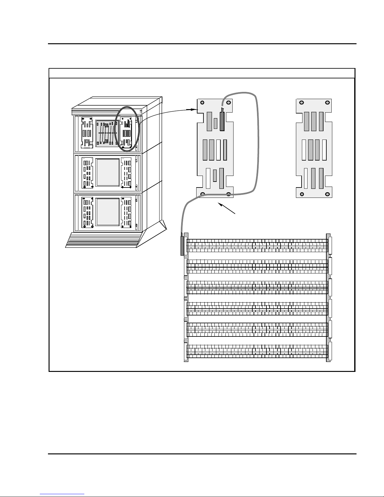
Figure 6
FEC
C
G
C
F
K
l
r
Connect the Meridian 1 to t he MDF
Install ISDN BRI hardware Page 25 of 46
Meridian 1
Rea
Meridian 1
IPE I/O panel
B
A
J2
G
J3
CE/PE I/O pane
B
A
E
H
NE-A25B External
Communication Cable
Main Distribution Frame
A
B
SILC/UILC port designations at the MDF
The tables th at follo w provid e SILC /UILC port desig nations a t the MDF , for
the NT8D37 IPE.
E
F
553-7697
ISDN B asic R at e Int e rfa c e Installatio n

Page 26 of 46 Install IS D N BR I ha r dware
Table 2 shows the SILC port designation labels for the I PE Module. The
UILC port designation labels for the IPE and CE/PE Modules is shown in
Table 3.
Tabl e 2
SILC port designations at the MDF: NT8D37 IPE Module (16-cable configur ati on)
(Part 1 of 2)
0
T-T+R+R-0T-T+R+R-1T-T+R+R-2T-T+R+R-3T-T+R+R-4T-T+R+R-5T-T+R+ R-6T-T+R+ R
A
1
T-T+R+R-0T-T+R+R-1T-T+R+R-2T-T+R+R-3T-T+R+R-4T-T+R+R-5T-T+R+ R-6T-T+R+ R
B
2
T-T+R+R-0T-T+R+R-1T-T+R+R-2T-T+R+R-3T-T+R+R-4T-T+R+R-5T-T+R+ R-6T-T+R+ R
C
3
T-T+R+R-0T-T+R+R-1T-T+R+R-2T-T+R+R-3T-T+R+R-4T-T+R+R-5T-T+R+ R-6T-T+R+ R
D
4
T-T+R+R-0T-T+R+R-1T-T+R+R-2T-T+R+R-3T-T+R+R-4T-T+R+R-5T-T+R+ R-6T-T+R+ R
E
5
T-T+R+R-0T-T+R+R-1T-T+R+R-2T-T+R+R-3T-T+R+R-4T-T+R+R-5T-T+R+ R-6T-T+R+ R
F
6
T-T+R+R-0T-T+R+R-1T-T+R+R-2T-T+R+R-3T-T+R+R-4T-T+R+R-5T-T+R+ R-6T-T+R+ R
G
7
T-T+R+R-0T-T+R+R-1T-T+R+R-2T-T+R+R-3T-T+R+R-4T-T+R+R-5T-T+R+ R-6T-T+R+ R
H
8
T-T+R+R-0T-T+R+R-1T-T+R+R-2T-T+R+R-3T-T+R+R-4T-T+R+R-5T-T+R+ R-6T-T+R+ R
K
9
T-T+R+R-0T-T+R+R-1T-T+R+R-2T-T+R+R-3T-T+R+R-4T-T+R+R-5T-T+R+ R-6T-T+R+ R
L
10
T-T+R+R-0T-T+R+R-1T-T+R+R-2T-T+R+R-3T-T+R+R-4T-T+R+R-5T-T+R+ R-6T-T+R+ R
M
11
T-T+R+R-0T-T+R+R-1T-T+R+R-2T-T+R+R-3T-T+R+R-4T-T+R+R-5T-T+R+ R-6T-T+R+ R
N
12
T-T+R+R-0T-T+R+R-1T-T+R+R-2T-T+R+R-3T-T+R+R-4T-T+R+R-5T-T+R+ R-6T-T+R+ R
R
13
T-T+R+R-0T-T+R+R-1T-T+R+R-2T-T+R+R-3T-T+R+R-4T-T+R+R-5T-T+R+ R-6T-T+R+ R
S
7
7
7
7
7
7
7
7
7
7
7
7
7
7
A
B
C
D
E
F
G
H
K
L
M
N
R
S
553-3901-200 Standard 7.00 January 2002

Install ISDN BRI hardware Page 27 of 46
Tabl e 2
SILC port designations at the MDF: NT8D37 IPE Module (16-cable configur ati on)
(Part 2 of 2)
14
T-T+R+R-0T-T+R+R-1T-T+R+R-2T-T+R+R-3T-T+R+R-4T-T+R+R-5T-T+R+ R-6T-T+R+ R
T
15
T-T+R+R-0T-T+R+R-1T-T+R+R-2T-T+R+R-3T-T+R+R-4T-T+R+R-5T-T+R+ R-6T-T+R+ R
U
Note 1: For the SILC port designations shown in this table, substitute Tx- Tx+ Rx+ Rx- for every
occurr ence of T- T+ R+ R-.
Note 2: The cable pair designated Tx- Tx+ is the transmit pair. The pair designated Rx+ Rx- is the
recei v e pair. An SILC port sup pl ies 2 w att s of pow e r at -48 V (-40 V fo r intern ati on al ), si mple xed ov e r the
tran smit and receive pairs, where the transmit pair is negative with respect t o the receive pair.
7
7
Tabl e 3
UILC port designation labels at the MDF: NT8D37 IPE Module (16-cable configuration)
(Part 1 of 2)
0
A TR
TR
TR
TR
TR
TR
TR
TR
T
U
A
0
1
B TR
0
2
C TR
0
3
D TR
0
4
E TR
0
5
F TR
0
6
G TR
0
7
H TR
0
8
K TR
1
TR
1
TR
1
TR
1
TR
1
TR
1
TR
1
TR
1
TR
2
TR
2
TR
2
TR
2
TR
2
TR
2
TR
2
TR
2
TR
3
TR
3
TR
3
TR
3
TR
3
TR
3
TR
3
TR
3
TR
4
TR
4
TR
4
TR
4
TR
4
TR
4
TR
4
TR
4
TR
5
TR
5
TR
5
TR
5
TR
5
TR
5
TR
5
TR
5
TR
6
TR
6
TR
6
TR
6
TR
6
TR
6
TR
6
TR
6
TR
7
TR
7
TR
7
TR
7
TR
7
TR
7
TR
7
TR
7
TR
B
C
D
E
F
G
H
K
0
1
2
3
4
5
6
7
ISDN B asic R at e Int e rfa c e Installatio n

Page 28 of 46 Install IS D N BR I ha r dware
Tabl e 3
UILC port designation labels at the MDF: NT8D37 IPE Module (16-cable configuration)
(Part 2 of 2)
9
L TR
TR
TR
TR
TR
TR
TR
TR
L
0
10
M TR
0
11
N TR
0
12
R TR
0
13
S TR
0
14
T TR
0
15
U TR
0
Note: The cable pair designated TR is a 2B1Q full duplex U interface.
1
TR
1
TR
1
TR
1
TR
1
TR
1
TR
1
2
TR
2
TR
2
TR
2
TR
2
TR
2
TR
2
3
TR
3
TR
3
TR
3
TR
3
TR
3
TR
3
4
TR
4
TR
4
TR
4
TR
4
TR
4
TR
4
TR
TR
TR
TR
TR
TR
5
5
5
5
5
5
5
6
TR
6
TR
6
TR
6
TR
6
TR
6
TR
6
7
TR
7
TR
7
TR
7
TR
7
TR
7
TR
7
M
N
R
S
T
U
Cross-connect the MDF
The MDF cross-connects NE-A25B cables conne cted to SILC and UILC
ports with bui lding wiring connected to ISDN BRI terminals.
Each SILC provide s e ight four-wire full duplex ports. These ports ar e
connected to building wiring to form DSLs. These ports are pola rity sensitive .
Signal polarity must be maintained along each loop.
Each UILC provides eight two-wire full duplex ports. These ports are
connected to twi sted pair buildi ng wiring to for m DSLs. These DSLs are not
polarity sensitive and, although it is recommended, it is not necessary to
maintain signal polarity along each loop.
Figure 7 and Figure 8 illustrate, respectively, a cross-connection of a n SILC
port and an UILC port to the building wiring.
553-3901-200 Standard 7.00 January 2002

Install ISDN BRI hardware Page 29 of 46
Cross- connect SIL C and/or UILC ports to the bui l di ng w iring
1 Identify t he card type (SILC or UILC) for a connector on the MDF.
Refer to the I PE or CE/PE module card l ocation fo rm, which shows the
card type connected to each I/O panel con nector.
2 Identify t ransmit and rec eive pairs on the top of the labeled distr ibution
strip for the ca rd t ype and m odule type you are conn ecting . To id entif y
SILC or UILC ports and their pin numbers, refer to Tables 4 through
10, which follow the i ll ustrations.
Note: In Tables 4 thro ugh 10, the cable pair designated T- T+ is the
transmit pair and the pair designated R+ R- is the receive pair of the
S/T interface. The cable pair designated T R is the Tx and Rx of the
2B1Q full duplex U interface.
3 Identify build ing wires connect ed t o the bo ttom of th e dist ribut ion st rip.
Refer to the Building Cable Plan, which identifies wires between
distribution frames and wall outl ets.
4 Plug in the termi nating resistor (Part Number A0378866) at the
appropriat e location in each S/T DSL. See “Engineeri ng Guidelines” in
the ISDN Basi c Rate Interfa ce: Product Descr iption (553-3901- 100) for
engineering rules and locat ions of terminating resistors.
ISDN B asic R at e Int e rfa c e Installatio n

Page 30 of 46 Install IS D N BR I ha r dware
Figure 7
Cross-connect the SILC port to the office wiring
1
2
3
4
5
6
7
8
9
10
11
12
13
14
15
16
17
18
19
20
21
22
23
24
25 50
Port 0
12345678910
26 27 29 30 31 32 33 34 3528
T- T+ R+ R- T- T+ R+ R- T- T+ R+ R- T- T+ R+ R- T- T+ R+ R-
A
Port 1
Cross connect wires or
cable for DS1
Distribution frame (Note 1)
Port 2 Port 3 Port 4
Port 0
Auxilary Power Source if more that 2 W
are required for DSL 1
B
Power Source 2
1234567891011121314151617181920
A
DSL 2 DSL 3
B
26
Port 0
27
28
Port 1
29
30
Port 2
31
32
Port 3
33
34
Port 4
35
36
Port 5
37
38
Port 6
39
40
Port 7
41
42
43
44
45
46
47
48
49
RJ - 45 type
wall outlet
1
2
3
4
5
6
7
8
1
2
3
4
5
6
7
8
R+
T+
TRPP+
R+
T+
TRPP+
WHT/ORG
BLU/WHT
WHT/BLU
ORG/WHT
GRN/WHT
WHT/GRN
WHT/ORG
BLU/WHT
WHT/BLU
ORG/WHT
GRN/WHT
WHT/GRN
DSL 1 wiring for
SILC Port 0
Maximum stub length
1 m or 3.3 feet
Loop terminator
resistor box
A0378866
NE-A25B cable connector connecting
distribution frame connector A
Note 1: Substitute Tx- Tx+ Rx- Rx+ for every occurance of T- T+ R-R+
Note 2: Transmit and receive labeling is from the network perspective
553-3901-200 Standard 7.00 January 2002
RJ - 45 type
wall outlet
100 Ohm

Figure 8
Cross-connec t the UILC port t o the office wiring
12345678910
26 27 29 30 31 32 33 34 3528
TR TR TR TR TR
A
Port 1Port 0 Port 2 Port 3 Port 4
Cross connect wires or
cable for DS1
B
DSL1
1234567891011121314151617181920
A
B
Install ISDN BRI hardware Page 31 of 46
Distribution frame
DSL 2
DSL 3
1
2
3
4
5
6
7
8
9
10
11
12
13
14
15
16
17
18
19
20
21
22
23
24
25 50
DSL 1 wiring for
26
Port 0
27
28
Port 1
29
30
Port 2
31
32
Port 3
33
34
Port 4
35
36
Port 5
37
38
Port 6
39
40
Port 7
41
42
43
44
45
46
47
48
49
NE-A25B cable connector connecting
RJ - 45 type
wall outlet
1
2
3
4
5
6
7
8
(U - Interface)
R+
T+
TRPP+
WHT/ORG
BLU/WHT
WHT/BLU
ORG/WHT
GRN/WHT
WHT/GRN
SILC Port 0
distribution frame connector A
553-7699
ISDN B asic R at e Int e rfa c e Installatio n

Page 32 of 46 Install IS D N BR I ha r dware
Tabl e 4
NT8D37 IPE m o du le
SILC and UILC pair-t erminations for connectors A, E, K, R (12-cable configur ati on)
Po rt signals
I/O panel connectors
Pairs Pair color
SILC UILC A E K R
0Tx - / 0Tx +
0Rx + / 0Rx -
1Tx - / 1Tx +
1Rx + / 1Rx -
2Tx - / 2Tx +
2Rx + / 2Rx -
3Tx - / 3Tx +
3Rx + / 3Rx -
4Tx - / 4Tx +
4Rx + / 4Rx -
5Tx - / 5Tx +
5Rx + / 5Rx -
6Tx - / 6Tx +
6Rx + / 6Rx -
0T / 0R 26 / 1
27 / 2
1T / 1R 28 / 3
29 / 4
2T / 2R 30 / 5
31 / 6
3T / 3R 32 / 7
33 / 8
4T / 4R 34 / 9
35 / 10
5T / 5R 36 / 11
37 / 12
6T / 6R 38 / 13
39 / 14
W -BL / BL-W
W-O / O-W
W-G / G-W
W -BR / BR-W
W -S / S-W
R -BL / BL-R
Rx-O / O-R
R -G / G-R
R-BR / BR-R
R-S / S-R
BK-BL / BL-BK
BK-O / O-BK
BK-G / G-BK
BK-BR / BK-BR
slot 0 slot 4 slot 8 slot 12 0
Card
port
1
2
3
4
5
6
7Tx - / 7Tx +
7Rx + / 7Rx -
7T / 7R 40 / 15
41 / 16
BK-S / S-BK
Y-BL / BL-Y
553-3901-200 Standard 7.00 January 2002
7

Install ISDN BRI hardware Page 33 of 46
Tabl e 5
NT8D37 IPE module
SILC and UILC pair-t erminations for connectors B, F, L, S (12-cable configuration)
Port si gnals
I/O panel connector s
Pairs Pair color
SILC UILC B F L S
0Tx - / 0Tx +
0Rx + / 0Rx -
1Tx - / 1Tx +
1Rx + / 1Rx -
2Tx - / 2Tx +
2Rx + / 2Rx -
3Tx - / 3Tx +
3Rx + / 3Rx -
4Tx - / 4Tx +
4Rx + / 4Rx -
5Tx - / 5Tx +
5Rx + / 5Rx -
6Tx - / 6Tx +
6Rx + / 6Rx -
0T / 0R 26 / 1
27 / 2
1T / 1R 28 / 3
29 / 4
2T / 2R 30 / 5
31 / 6
3T / 3R 32 / 7
33 / 8
4T / 4R 34 / 9
35 / 10
5T / 5R 36 / 11
37 / 12
6T / 6R 38 / 13
39 / 14
W -BL / BL-W
W-O / O-W
W-G / G-W
W -BR / BR-W
W -S / S-W
R-BL / BL-R
R-O / O-R
R-G / G-R
R-BR / BR-R
R-S / S-R
BK-BL / BL-BK
BK-O / O-BK
BK-G / G-BK
BK-BR / BK-BR
slot 1 slot 5 slot 9 slot 13 0
Card
port
1
2
3
4
5
6
7Tx - / 7Tx +
7Rx + / 7Rx -
0Tx - / 0Tx +
0Rx + / 0Rx -
1Tx - / 1Tx +
1Rx + / 1Rx -
2Tx - / 2Tx +
2Rx + / 2Rx -
3Tx - / 3Tx +
3Rx + / 3Rx -
7T / 7R 40 / 15
41 / 16
0T / 0R 42 / 17
43 / 18
1T/ 1R 44 / 19
45 / 20
2T / 2R 46 / 21
47 / 22
3T / 3R 48 / 23
49 / 24
BK-S / S-BK
Y-BL / BL-Y
Y-O / O-Y
Y-G / G-Y
Y-BR / BR-Y
Y-S / S-Y
V-BL / BL-V
V- O / V-O
V- G / G-V
V-BR / BR-V
7
slot 2 slot 6 slot 10 slot 14 0
1
2
3
ISDN B asic R at e Int e rfa c e Installatio n

Page 34 of 46 Install IS D N BR I ha r dware
Tabl e 6
NT8D37 IPE m o du le
SILC and UILC pair-t erminations for connectors C, G, M, T (12-cable configuration)
Port si gnals
I/O panel connector s
Pairs Pair color
SILC UILC C G M T
4Tx - / 4Tx +
4Rx + / 4Rx -
5Tx - / 5Tx +
5Rx + / 5Rx -
6Tx - / 6Tx +
6Rx + / 6Rx -
7Tx - / 7Tx +
7Rx + / 7Rx -
0Tx - / 0Tx +
0Rx + / 0Rx -
1Tx - / 1Tx +
1Rx + / 1Rx -
2Tx - / 2Tx +
2Rx + / 2Rx -
4T / 4R 26 / 1
27 / 2
5T / 5R 28 / 3
29 / 4
6T / 6R 30 / 5
31 / 6
7T / 7R 32 / 7
33 / 8
0T / 0R 34 / 9
35 / 10
1T / 1R 36 / 11
37 / 12
2T / 2R 38 / 13
39 / 14
W -BL / BL-W
W-O / O-W
W-G / G-W
W -BR / BR-W
W -S / S-W
R-BL / BL-R
R-O / O-R
R-G / G-R
R-BR / BR-R
R-S / S-R
BK-BL / BL-BK
BK-O / O-BK
BK-G / G-BK
BK-BR / BK-BR
slot 2 slot 6 slot 10 slot 14 4
slot 3 slot 7 slot 11 slot 15 0
Card
port
5
6
7
1
2
3Tx - / 3Tx +
3Rx + / 3Rx -
4Tx - / 4Tx +
4Rx + / 4Rx -
5Tx - / 5Tx +
5Rx + / 5Rx -
6Tx - / 6Tx +
6Rx + / 6Rx -
7Tx - / 7Tx +
7Rx + / 7Rx -
3T / 3R 40 / 15
41 / 16
4T / 4R 42 / 17
43 / 18
5T / 5R 44 / 19
45 / 20
6T / 6R 46 / 21
47 / 22
7T / 7R 48 / 23
49 / 24
BK-S / S-BK
Y-BL / BL-Y
Y-O / O-Y
Y-G / G-Y
Y-BR / BR-Y
Y-S / S-Y
V-BL / BL-V
V- O / V-O
V- G / G-V
V-BR / BR-V
553-3901-200 Standard 7.00 January 2002
3
4
5
6
7

Install ISDN BRI hardware Page 35 of 46
Connect the ISDN BRI terminals to the DSL
ISDN BRI terminals are connected to DSLs using modular cables up to 10
meters (33 feet) long, with RJ-45 plugs on each end. One end of the cable
plugs int o the te rminal and the other end plugs into the wall outlet.
Note: All ISDN BRI terminals should comply with CCITT , ANSI,
ETSI NET-3, INS NET-64, National ISDN, 1TR6, Numeris VN2, and
D70 standards for terminals, and be compatible with Meridian 1. For a
list of co m p at ib le ter m i na l s , re f er to th e ISDN Ba si c Ra te Int erf a ce :
Product Description (553-3901-100) .
Figure 9 illustrates a terminal connection to the S/T interface; Figure 10
illust rates a network termination (NT1) connection to the U interface.
1 Plug one end of the modular cable into the ISDN BRI interface
connector on the t erminal , and th e oth er end of the mod ular ca ble int o
the wall outle t.
2 For an SILC S/T interface terminal with an optional auxiliary power
source, plug the power source into the wall outlet, then plug the cable
into the power source's RJ-45 jack. This power source must supply
power only to the local ISDN BRI terminal, not back into th e DSL
through the RJ-45 wal l outlet. The power adapter i s supplied with the
terminal.
3 Program the terminal parameters, such as the SPID and TEI, as
required by the type of terminal. For detailed information pertaining to
this procedure, refer to the section “Initialize ISDN BRI terminals”,
found in ISDN Basic R ate Inte rface: A d m inistration (553-3901-300).
4 Repeat steps 1 and 3 for each terminal to be connect ed.
—————————— End of Proce d u re ——————————
Connect the terminating resistors
DSLs requir e that a terminating resistor
(Part Number A0378866) be
connected at the end of each loop. See ISDN Basic Rate Interface: Product
Description (553-3901-100) , for engineering r u les and locations of
terminati ng res istors. The end of the S/T inte rface loop has a RJ-45 jack to
plug in the tel ephone cable. Plug the terminating resistor into the RJ-45 and
then plug t he tele phone cable in to the t erminating r esisto r. Note tha t for every
port there is one loop with only one te rmi nating resistor per loop. Each loop
may have up to eight telephones.
ISDN B asic R at e Int e rfa c e Installatio n

Page 36 of 46 Install IS D N BR I ha r dware
Figure 9
Connect the ISDN BRI terminal to the S/T interface
Optional Power Adapter
RJ-45 type plug
1
2
3
4
5
6
7
8
RJ-45 type
wall outlet
S/T interface
Optional
external power
source (PS 52)
3
4
5
6
7
8
DSL wiring
1
2
R+
T+
TRP-
P+
WHT/ORG
BLU/WHT
WHT/BLU
ORG/WHT
GRN/WHT
WHT/GRN
3
4
5
6
7
8
Modular cable
(maximum
length 10 m)
Voice Data
terminal
3 Rx+
4 Tx+
5 Tx6 Rx-
7 P8 P+
Printer
1
2
3 Tx+
4 Rx+
S/T interface connector
on the ISDN/BRI terminal
553-3901-200 Standard 7.00 January 2002
5 Rx6 Tx-
7 P8 P+
553-7700

Install ISDN BRI hardware Page 37 of 46
Figure 10
Connect the ISDN BRI network term ination (NT1) to the U interface
RJ-45 type
wall outlet
RJ - 45
type plug
4 R
5T
U Interface Connector on
the Network Termination
(NT1)
RJ - 45
type plug
4 R
5T
Modular cable maximum
length 10 m
1
2
3
4 R
5 T
6
7
8
NT1
power source
U U+ U+S/TS/T
NT1
1
2
3
4R
5T
6
7
8
U interface
1
2
R+ 3
T+ 4
T- 5
R- 6
P
-7
P
+
8
S/T Interface Connector on
the Network Termination
(NT1)
Office Wiring
Terminal Auxiliary
power source PS 2
S/T interface DSL cable to
the ISDN BRI terminals
WHT/ORG Rx + 3
BLU/WHT Tx + 4
WHT/BLU Tx - 5
ORG/WHT Rx - 6
GRN/WHT P - 7
WHT/GRN P+ 8
RJ - 45
type plug
553-7701
ISDN B asic R at e Int e rfa c e Installatio n

Page 38 of 46 Install IS D N BR I ha r dware
Install ISDN BRI hardware for trunk applications
The following lists the procedures for install ISDN BRI hardware for ISDN
BRI trunk applications. Meridian 1 must already be installed and operating
according to the instru ctions in System Insta llation Procedur es
(553-3001-210) before performing these procedures.
For a successful ins tallation, perf orm these procedures in the order listed
below:
1 Select the card sl ots where the ISDN BRI cards will be loc ated
2 Install the MISP
3 Install clock referencing on th e SILC
4 Install the SILC and/or UI LC
5 Connect Meridian 1 to the MDF
6 Cross-connect the MDF (in Termina l Equipment mode)
Note: The Meridian 1, in Tie trunk or CO connectivity, requires a
different wiri ng configurat ion than for a line app lication; th e transmit and
receive pai rs should be reversed, as illus trated in Figure 12.
Select the card slots
Follow the same proc edures as describe d earlier for line applications (refer to
“Se le ct th e ca r d sl ot s ” on page 15).
Remove the module cover for card installation
Follow the same proc edures as describe d earlier for line applications (refer to
“Remove the module cover for card installation” on page 19).
Install the MISP
Follow the same proc edures as describe d earlier for line applications (refer to
“In st all the MI S P” on page 20).
Install the clock reference on the SILC
The DSL#0 and DSL#1 on an SILC card can be configured as the reference
clock sourc e, with DSL#0 being assig ned for the prim ary clock refere nce and
DSL#1 being assigne d for the secondary clock refere nce .
553-3901-200 Standard 7.00 January 2002

Install ISDN BRI hardware Page 39 of 46
The loop number and location of the primary and secondary clock s ource is
configure d in the Digit al Data B lock overl ay 73. Refer to the ISD N Basi c Rate
Interface : Admi nistration (553-3901-300).
The following proc edure shoul d be followe d to pro vide clock re ferenc ing on
the SILC.
Note: For procedures on how to install the QPC775/QPC471 Clock
Controlle r on the vari ous Meri dian 1 syst ems, pl ease refer to ISDN PRI:
Installation (553-2901-201).
1 Maintai n the same polarity on each tran sm it and receive. Rewire the
selecte d Tx and Rx pairs (applica ble to DSL0 and DSL1), to exchange
the Tx and Rx pair position. Thi s rewiring is done at the Main
Distribut ion Frame (MDF).
2 Remove the phantom power jumpers (two jumpe rs per DSL) from the
pin headers .
3 Place the SILC in the selected IPE slot.
4 Configure the sel ected DSL as TE mode (in overlay 27).
5 Enable the clock in overlay 60, to output the clock references to the
IPE back plane pins.
6 Configure the Cl ock Controller card to accept ISDN BRI clock
reference.
7 Check the appropriate messages from the Clock Controller to ensure
that it i s synchr oni zed to the pro per clock r efere nce ( this is done using
overlay 60).
8 Connect the ISDN BRI clock refer ence cab les to the Clock Control ler,
using the procedures which follow.
—————————— End of Proce d u re ——————————
ISDN B asic R at e Int e rfa c e Installatio n

Page 40 of 46 Install IS D N BR I ha r dware
Connect clock reference cables
The following proc edur e should be follo wed to connec t the ISDN BRI clock
refe renc e c abl es to t he Cl ock Controller . Th er e a re t hree dif f ere nt c abl es th at
route clock s ignals from the IPE back plane to the Clock Controll er face plate
(as shown in Figure 11). These are shown in Table 7.:
Tabl e 7
ISDN BRI clock reference tables
Code Length (feet) Use
NTND70AA 1.5 Connects IPE back plane to
NTND71AA-AD 6.5, 12, 25, 42 Connects IPE I/O to CE I/O
NTND72AA 6.5 Connects CE I/O to Clock
IPE I/O panel.
panel.
Controller face plate.
Note: Measure the dist ance between the IPE and CE modules to ensure
that you order the correct cable lengths.
1 Search for avail able D-sub 9 connector slots on the I/O panels of the
selecte d IPE and CE I/O modules (if the I/O panel is equipp ed with
D-sub 9 connector slots). If none is available, look for an empty slot
used for 25 pair wire conn ectors ( the cable s contain two adapte r plates
to convert an 25 wire slot to two D-sub 9 connector slots).
2 Connect the cables as shown in Figure 11; if choosing IPE slots 0, 4,
8, or 12 the tr ansmit and r eceiv e cab le in stalled o n pi ns 72 - 79 s hould
be removed and secured to a proper place.
553-3901-200 Standard 7.00 January 2002

Figure 11
Clock reference cable connection
NTND71AA - AD
NTND70AA
Install ISDN BRI hardware Page 41 of 46
IPE I/O panel
S
I
L
C
IPE shelf
NTND72AA
CE I/O panel
C
C
CE shelf
553-7702
Clock recovery
The SILC is configured in the slave-sla ve mo de whe n act ing as a trunk
interfa ce. This is se t up through the Maintenanc e Signaling Channel (MSC) .
The microcontroller configures the S/T chips on the SILC as appropriate.
The SILC may re cover the n etwork clock from the receiv ed data str eam using
on-chip phase lock loops. The clock frequency which is recovered is 2.56
MHz. The jitte r and wan der conform to CCITT recommendations.
ISDN B asic R at e Int e rfa c e Installatio n

Page 42 of 46 Install IS D N BR I ha r dware
All of the S /T c hips o n th e SI LC c ould be co nfigu red as Term inal Equ ipmen t
Slaves (TES), but onl y the clocks re covered from DSL0 and DSL1 are routed
to the back plane connector pins. Thes e cl ocks are provided as differ ential
pairs on back pla ne pins, as follows: in
Tabl e 8
Clocks as differential pairs
Differential pairs Pin # Row A Row B
Primary 73 +Ref 0A - Ref 0A
Primary 74 +Ref 1A - Ref 1A
Secondary 75 +Ref 0B - Ref 0B
Secondary 76 +Ref 1B - Ref 1A
Automatic c lock recovery is done upon the exp iration of the free run guard
timer. Tracking is restored to the primary reference clock, if defined. If the
primary refere nce clock is disable d, tracking is restore d to the secondary
reference clock, if defined.
Install the SILC and the UILC
Follow the same proc edures as describe d earlier for line applications (refer to
“Install t he BRSC, SILC and UILC” on page 21).
Connect Meridian 1 to the Main Distribution Frame (MDF)
Follow the same proc edures as describe d earlier for line applications (refer to
“Connect Meridian 1 modul es to the MDF” on pag e 2 4) .
Cross-connect the Main Distribution Frame (MDF)
The Meridian 1, in Tie trunk or CO connectivity, requires a different wiring
configura tion than for a line applica tion; the transmit and receive pairs shoul d
be reversed, as illustrated in Figure12.
553-3901-200 Standard 7.00 January 2002

Install ISDN BRI hardware Page 43 of 46
Figure 12
Connect the network termination to the U interface and to the S/T interface (in TE mode)
Distribution Frame
26 1 27 2 28 3 29 4 30 5 31 6
R
T
1234 5 6 789 1011
TR T R
Port 0 Port 1 Port 2
Cross-connectwires
or cable for DSL 1
DSL 1 DSL 2
DSL 1 wiring for
UILC Port 0
BLU/WHT T
WHT/BLU R
1
2
3
4
5
6
7
8
Distribution Frame
Port 0
26 1 27 2 28 3 29 4 30 5 31 6
Tx- Rx-Tx+ Rx+
12
Network Termination (NT1)
1 23 45 6789101112
Tx-
Tx+ Rx+ Tx- Rx-Tx+ Rx+
Rx-
Port 1 Port 2
Cross-connectwires
or cable for DSL 1
DSL 1 Wiring
for SILC Port 0
1
2
Tx-
3
Rx-
4
5
Rx+
6
Tx+
7
8
DSL 2
WHT/ORG
BLU/WHT
WHT/BLU
ORG/WHT
U Interface Connector on
the Network Termination
(NT1)
1
2
3
4 T
5 R
6
7
8
1
2
Tx- 3
Rx- 4
Rx+ 5
Tx+ 6
7
8
S/T Interface Connector on
the Network Termination
(NT1)
553-7703
ISDN B asic R at e Int e rfa c e Installatio n

Page 44 of 46 Install IS D N BR I ha r dware
Card loca tion forms
The following card location forms may be used when installing SILC/U ILC
and BRSC cards on the Meridian 1.
Tabl e 9
Card location form: NT8D37 IPE Module (16-cable configuration)
Card type
(SILC/UILC/BRSC)
IPE Module
number
IPE Module
slot number
0A 0–7
1B 0–7
2C 0–7
3D 0–7
4E 0–7
5F 0–7
6G 0–7
7H 0–7
8K 0–7
9L 0–7
10 M 0–7
I/O panel
connector
SILC/UILC/BRSC
ports
553-3901-200 Standard 7.00 January 2002
11 N 0–7
12 R 0–7
13 S 0–7
14 T 0–7
15 U 0–7

Install ISDN BRI hardware Page 45 of 46
Tabl e 10
Card location form: NT8D37 IPE Module (12-cable configuration)
Card Type
(SILC/UILC or BRSC)
IPE Module
number
IPE module
slo t nu m ber
I/O panel
connector
0A 0–7
1B 0–7
2BC0–3
3C 0–7
4E 0–7
5F 0–7
6FG0–3
7G 0–7
8K 0–7
9L 0–7
SILC/UILC or BRSC
ports
4–7
4–7
10 L
M
0–3
4–7
11 M 0–7
12 R 0–7
13 S 0–7
14 S
T
0–3
4–7
ISDN B asic R at e Int e rfa c e Installatio n

Page 46 of 46 Install IS D N BR I ha r dware
553-3901-200 Standard 7.00 January 2002


Family Product Manual Contacts Copyright FCC notice Trademarks
Document number Product release Document release Date Publish
Meridian 1
ISDN Basic Rate Interface
Installation
Copyright © 1992–2002 Nortel Networks
All Rights Reserved
Information is subject to change without notice. Nortel
Networks reserves the right to make changes in
desig n or compone nt s as pro gr e ss in engi ne er ing an d
manufacturing may warrant. This equipment has been
test ed an d f ou nd to c omp ly wit h th e li mi ts f or a Cla ss A
digital device pur suant to Part 15 of the FCC rules,
and the radio interference regulations of Industry
Canada. The se limit s are designed to provide
reasonable protection against harmful interference
when the equi pment i s operated in a commercial
envi ron ment. Th is equ ipmen t gener ate s, uses an d can
radiate radio frequency energy, and if not installed and
used in accordance with the instruction manual, may
cause harmful interference to radio communications.
Operation of this equipm ent in a residential area is
likely to cause harmful interference in which case the
user will be required t o correct the interference a t their
own expens e.
SL-1 and Meridian 1 are t rademark of Nortel
Networks.
Publication number: 553-3901-200
Document release: Standard 7.00
Date: January 2002
Printed in Canada
TM
 Loading...