

Page 1

Enterprise: Common
Solution Integration Guide
for Communication Server
1000/Multimedia Communication
Server 5100
Clicking on a PDF hyperlink takes you to the appropriate page. If necessary,
scroll up or down the page to see the beginning of the referenced section.
NN49000-301
.
ATTENTION
Page 2

Document status: Standard
Document version: 01.01
Document date: 27 October 2006
Copyright © 2006, Nortel Networks
All Rights Reserved.
The information in this document is subject to change without notice. The statements, configurations, technical
data, and recommendations in this document are believed to be accurate and reliable, but are presented without
express or implied warranty. Users must take full responsibility for their applications of any products specified in this
document. The information in this document is proprietary to Nortel Networks.
Nortel, the Nortel logo and the Globemark are trademarks of Nortel Networks.
Microsoft, MS, MS-DOS, Windows, and Windows NT are registered trademarks of Microsoft Corporation.
All other trademarks and registered trademarks are the property of their respective owners.
Sourced in Canada.
Page 3

Contents
How to get help 5
Finding the latest updates on the Nortel Web site 5
Getting help from the Nortel Web site 6
Getting help over the phone from a Nortel Solutions Center 7
Getting help from a specialist by using an Express Routing Code 7
Getting help through a Nortel distributor or reseller 7
About this document 9
Audience 9
Overview 11
Prerequisites 17
Knowledge requirements 17
Capturing integration parameters 18
Establishing the system baseline 20
IP Peer Networking and Call Server configuration 23
IP Peer Networking and Call Server configuration procedures 23
IP Peer Networking configuration 24
Call Server configuration 55
3
Defining LDN0 25
Defining customer to support ISDN 26
Configuring the SIP Gateway 29
Enabling the SIP Virtual Trunk application 31
Configuring the SIP Redirect Server and URI map 34
Creating the virtual D-channel 36
Configuring zones (LD 117) 38
Creating the virtual route (LD 16) 41
Creating the virtual trunks (LD 14) 43
Creating the Network Control Block (NCTL) for network access (LD 87) 45
Creating the ESN data block for CDP 46
Creating the RLB for the virtual trunk route (LD 86) 49
Creating the CDP steering codes (LD 87) 51
Checking CODEC and QoS settings 53
Configuring Application Module Link (LD 17) 55
Solution Integration Guide for Communication Server 1000/Multimedia Communication Server 5100
Copyright © 2006, Nortel Networks Nortel Networks Confidential
.
Enterprise: Common
NN49000-301 01.01 Standard
Release 4.5 27 October 2006
Page 4

4 Contents
Configuring Value Added Server (LD 17) 56
Configuring the Automatic Call Distribution Directory Number (LD 23) 57
Configuring a Control Directory Number (LD 23) 58
Configuring Service DN for Converged Desktop (LD 90) 59
Configuring Personal Call Assistant (LD 11) 60
Configuring the Signaling Server 62
Configuring Converged Desktop users (LDs 10/11) 67
MCS 5100 configuration 68
Adding IP address of IP Telephony node to the application server as an
authenticated server 69
Logging on to the MCS Provisioning Client 70
Configuring the SIP Gateway, trunk, and trunk group 71
Configuring a new Gateway route 72
Adding a trunk group directed to the Gateway route 73
Configuring Number Qualifiers 74
Configuring Telephony Route Class of Service (COS) 76
Configuring telephony routes for each dialing plan 77
Configuring a new route list 79
Configuring the pretranslation table 80
Converged desktop user configuration 81
Configuring a service package 81
Configuring a converged desktop user 82
NRS configuration 85
NRS configuration procedures 85
Launching NRS Manager 85
Verifying and adjusting system-wide settings 87
Configuring the NRS server settings (H.323 Gatekeeper or SIP) 89
Configuring the service domain 91
Configuring the L1 domain (UDP) 92
Configuring the L0 domain (CDP) 95
Configuring Gateway endpoints 98
Configuring routing entries 102
Configuring collaborative servers 104
Updating the database 106
Checking the status of registered endpoints 107
Checking the status of virtual D-channels 108
Checking the status of virtual trunks 109
Integration example 113
Solution Integration Guide for Communication Server 1000/Multimedia Communication Server 5100
Copyright © 2006, Nortel Networks Nortel Networks Confidential
.
Enterprise: Common
NN49000-301 01.01 Standard
Release 4.5 27 October 2006
Page 5

How to get help
This chapter explains how to get help for Nortel products and services.
Finding the latest updates on the Nortel Web site
The content of this documentation is current at the time of product
release. To check for updates to the latest documentation and software for
Communication Server 1000 (CS 1000) and Multimedia Communication
Server 5100 (MCS 5100), click one of the following links:
5
For the...
Latest CS 1000E software Nortel page for CS 1000E software located at:
Latest CS 1000M Cabinet/Chassis software Nortel page for CS 1000M Cabinet/Chassis
Latest CS 1000M Half Group/Single
Group/Multi-Group software
Latest CS 1000S software Nortel page for CS 1000S software located at:
Latest MCS 5100 software Nortel page for MCS 5100 software located at:
Go to...
http://www130.nortelnetworks.com/go/main.jsp
?cscat=SOFTWARE&resetFilter=1&poid=142
61
software located at:
http://www130.nortelnetworks.com/go/main.jsp
?cscat=SOFTWARE&resetFilter=1&poid=125
15
Nortel page for CS 1000M Half Group/Single
Group/Multi-Group software located at:
http://www130.nortelnetworks.com/go/main.jsp
?cscat=SOFTWARE&resetFilter=1&poid=125
16
http://www130.nortelnetworks.com/go/main.jsp
?cscat=SOFTWARE&resetFilter=1&poid=125
14
http://www130.nortelnetworks.com/go/main.jsp
?cscat=SOFTWARE&resetFilter=1&poid=124
82
Solution Integration Guide for Communication Server 1000/Multimedia Communication Server 5100
Copyright © 2006, Nortel Networks Nortel Networks Confidential
.
Enterprise: Common
NN49000-301 01.01 Standard
Release 4.5 27 October 2006
Page 6

6 How to get help
For the...
Latest CS 1000E documentation Nortel page for CS 1000E documentation
Latest CS 1000M Cabinet/Chassis
documentation
Latest CS 1000M Half Group/Single Group/
Multi-Group documentation
Latest CS 1000S documentation Nortel page for CS 1000S documentation
Latest MCS 5100 documentation Nortel page for MCS 5100 documentation
Go to...
located at:
http://www130.nortelnetworks.com/go/
main.jsp?cscat=DOCUMENTATION&resetFilte
r=1&poid=14261
Nortel page for CS 1000M Cabinet/Chassis
documentation located at:
http://www130.nortelnetworks.com/go/
main.jsp?cscat=DOCUMENTATION&resetFilte
r=1&poid=12515
Nortel page for CS 1000M Half Group/Single
Group/ Multi-Group documentation located at:
http://www130.nortelnetworks.com/go/
main.jsp?cscat=DOCUMENTATION&resetFilte
r=1&poid=12516
located at:
http://www130.nortelnetworks.com/go/
main.jsp?cscat=DOCUMENTATION&resetFilte
r=1&poid=12514
located at:
http://www130.nortelnetworks.com/go/main.js
p?cscat=DOCUMENTATION&resetFilter=1&p
oid=12482
Getting help from the Nortel Web site
The best way to get technical support for Nortel products is from the Nortel
Technical Support Web site:
w
ww.nortel.com/support
This site provides quick access to software, documentation, bulletins, and
tools to address issues with Nortel products. From this site, you can:
•
download software, documentation, and product bulletins
•
search the Technical Support Web site and the Nortel Knowledge Base
for answers to technical issues
•
sign up for automatic notification of new software and documentation
for Nortel equipment
•
open and manage technical support cases
Solution Integration Guide for Communication Server 1000/Multimedia Communication Server 5100
Copyright © 2006, Nortel Networks Nortel Networks Confidential
.
Enterprise: Common
NN49000-301 01.01 Standard
Release 4.5 27 October 2006
Page 7

Getting help through a Nortel distributor or reseller 7
Getting help over the phone from a Nortel Solutions Center
If you do not find the information you require on the Nortel Technical Support
Web site, and you have a Nortel support contract, you can also get help
over the phone from a Nortel Solutions Center.
In North America, call 1-800-4NORTEL (1-800-466-7835).
Outside North America, go to the following Web site to obtain the phone
number for your region:
ww.nortel.com/callus
w
Getting help from a specialist by using an Express Routing Code
Toaccess some NortelTechnicalSolutions Centers, you can use an Express
Routing Code (ERC) to quickly route your call to a specialist in your Nortel
product or service. To locate the ERC for your product or service, go to:
ww.nortel.com/erc
w
Getting help through a Nortel distributor or reseller
If you purchase a service contract for your Nortel product from a distributor
or authorized reseller, you can contact the technical support staff for that
distributor or reseller.
Solution Integration Guide for Communication Server 1000/Multimedia Communication Server 5100
Copyright © 2006, Nortel Networks Nortel Networks Confidential
.
Enterprise: Common
NN49000-301 01.01 Standard
Release 4.5 27 October 2006
Page 8

8 How to get help
Solution Integration Guide for Communication Server 1000/Multimedia Communication Server 5100
Enterprise: Common
NN49000-301 01.01 Standard
Copyright © 2006, Nortel Networks Nortel Networks Confidential
.
Release 4.5 27 October 2006
Page 9

About this document
This document describes the Session Initiated Protocol Converged Desktop
System (SIP CDS) and the planning, configuration, and troubleshooting
steps required for the Multimedia Communication Server 5100 (MCS 5100)
and Communication Server 1000 (CS 1000) systems. Use this document
as a reference tool to design or configure a converged desktop environment
between the MCS 51000 and CS 1000 systems.
The following systems and software releases are covered in this guide:
• Communication Server 1000 Release 4.5
•
Multimedia Communication Server 5100 Release 3.5
This document is intended to be a stand-alone guide, covering the
prerequisites to and implementation of a successful MCS 5100/CS 1000
integration. A minimum skill set and level of understanding is assumed.
The screen printouts shown in this document are taken from a configured
system and may vary from your system. "Integration example" (page 113)
9
Audience
The intended audience for this document includes network planners,
installers, and maintenance personnel.
Solution Integration Guide for Communication Server 1000/Multimedia Communication Server 5100
Copyright © 2006, Nortel Networks Nortel Networks Confidential
.
Enterprise: Common
NN49000-301 01.01 Standard
Release 4.5 27 October 2006
Page 10

10 About this document
Solution Integration Guide for Communication Server 1000/Multimedia Communication Server 5100
Enterprise: Common
NN49000-301 01.01 Standard
Copyright © 2006, Nortel Networks Nortel Networks Confidential
.
Release 4.5 27 October 2006
Page 11

Overview
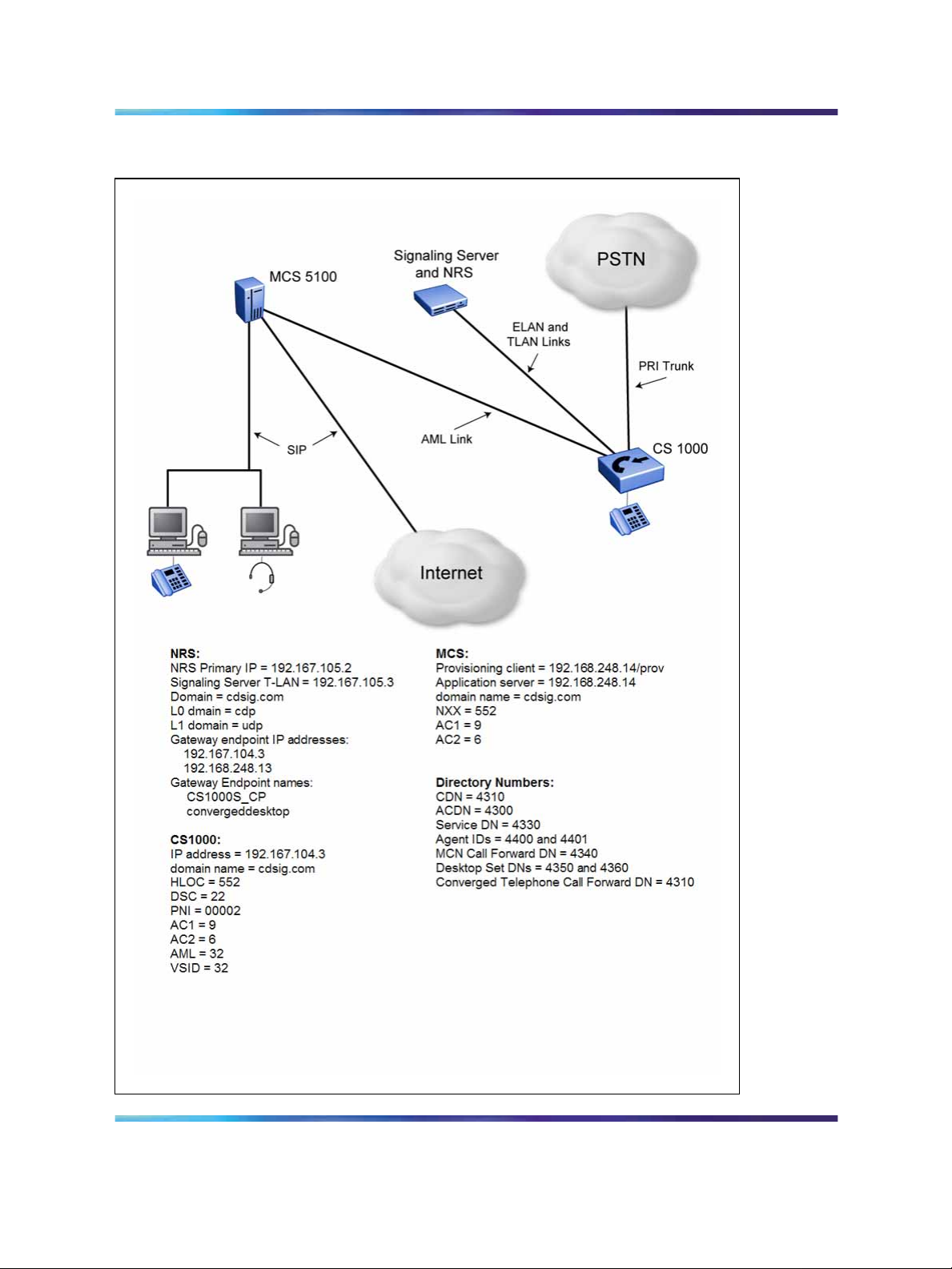
An example of a Communication Server 1000 (CS 1000)/Multimedia
Communication Server 5100 (MCS 5100) systems integration is shown in
Figure 1 "CS 1000/MCS 5100 architecture" (page 12).
11
Solution Integration Guide for Communication Server 1000/Multimedia Communication Server 5100
Copyright © 2006, Nortel Networks Nortel Networks Confidential
.
Enterprise: Common
NN49000-301 01.01 Standard
Release 4.5 27 October 2006
Page 12
12 Overview
Figure 1 CS 1000/MCS 5100 architecture
Solution Integration Guide for Communication Server 1000/Multimedia Communication Server 5100
Enterprise: Common
NN49000-301 01.01 Standard
Copyright © 2006, Nortel Networks Nortel Networks Confidential
.
Release 4.5 27 October 2006
Page 13
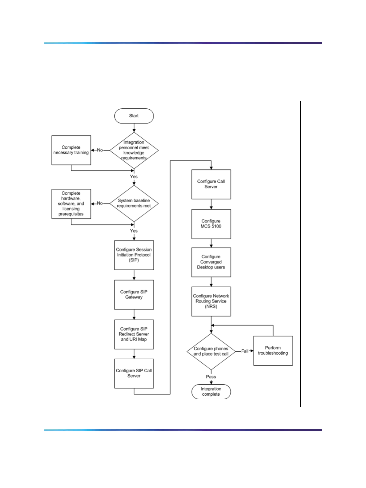
Figure 2 "CS 1000/MCS 5100 integration process" (page 13) shows the
sequence of procedures you perform to integrate the CS 1000 and MCS
5100 systems.
Figure 2 CS 1000/MCS 5100 integration process
Overview 13
Solution Integration Guide for Communication Server 1000/Multimedia Communication Server 5100
Copyright © 2006, Nortel Networks Nortel Networks Confidential
.
Enterprise: Common
NN49000-301 01.01 Standard
Release 4.5 27 October 2006
Page 14

14 Overview
The tasks in the MCS 5100/CS 1000 systems integration process are listed
in Table 1 "Task Completion Checklist" (page 14). Use this checklist to
implement the integration.
Table 1
Task Completion Checklist
Task Reference
Configure the SIP protocol
Configure the SIP Gateway "Configuring the SIP Gateway" (page 29)
1. "Defining LDN0" (page 25)
2. "Defining customer to support ISDN" (page 26)
"Enabling the SIP Virtual Trunk application" (page 31)
Configure the SIP Redirect
Server and URI Map
Configure the SIP Call Server
Configure CS 1000 users
"Configuring the SIP Redirect Server and URI map"
(page 34)
1. "Creating the virtual D-channel" (page 36)
2. "Configuring zones (LD 117)" (page 38)
3. "Creating the virtual route (LD 16)" (page 41)
4. "Creating the virtual trunks (LD 14)" (page 44)
5. "Creating the Network Control Block (NCTL) for
network access (LD 87)" (page 45)
6. "Creating the ESN data block for CDP" (page 46)
7. "Creating the RLB for the virtual trunk route (LD 86)"
(page 49)
8. "Creating the CDP steering codes (LD 87)" (page 51)
9. "Checking CODEC and QoS settings" (page 53)
1. "Configuring Application Module Link (LD 17)" (page
55)
2. "Configuring Value Added Server (LD 17)" (page 56)
3. "Configuring the Automatic Call Distribution
Directory Number (LD 23)" (page 57)
4. "Configuring a Control Directory Number (LD 23)"
(page 58)
5. "Configuring Service DN for Converged Desktop
(LD 90)" (page 59)
6. "Configuring Personal Call Assistant (LD 11)" (page
61)
7. "Configuring the Signaling Server" (page 62)
8. "Configuring Converged Desktop users (LDs 10/11)"
(page 67)
Solution Integration Guide for Communication Server 1000/Multimedia Communication Server 5100
Copyright © 2006, Nortel Networks Nortel Networks Confidential
.
Enterprise: Common
NN49000-301 01.01 Standard
Release 4.5 27 October 2006
Page 15

Task Reference
Configure MCS 5100 users
1. "Adding IP address of IP Telephony node to the
application server as an authenticated server" (page
69)
2. "Logging on to the MCS Provisioning Client" (page
71)
3. "Configuring the SIP Gateway, trunk, and trunk
group" (page 71)
4. "Configuring a new Gateway route" (page 72)
5. "Adding a trunk group directed to the Gateway
route" (page 73)
6. "Configuring Number Qualifiers" (page 74)
7. "Configuring Telephony Route Class of Service
(COS)" (page 76)
8. "Configuring telephony routes for each dialing plan"
(page 77)
9. "Configuring a new route list" (page 79)
Overview 15
Configure Converged Desktop
users
Configure NRS
10. "Configuring the pretranslation table" (page 80)
1. "Configuring a service package" (page 81)
2. "Configuring a converged desktop user" (page 83)
1. "Launching NRS Manager" (page 86)
2. "Verifying and adjusting system-wide settings" (page
88)
3. "Configuring the NRS server settings (H.323
Gatekeeper or SIP)" (page 90)
4. "Configuring the service domain" (page 91)
5. "Configuring the L1 domain (UDP)" (page 92)
6. "Configuring the L0 domain (CDP)" (page 95)
7. "Configuring Gateway endpoints" (page 98)
8. "Configuring routing entries" (page 102)
9. "Configuring collaborative servers" (page 104)
10. "Updating the database" (page 106)
11. "Checking the status of registered endpoints" (page
107)
12. "Checking the status of virtual D-channels" (page
108)
13. "Checking the status of virtual trunks" (page 109)
Solution Integration Guide for Communication Server 1000/Multimedia Communication Server 5100
Copyright © 2006, Nortel Networks Nortel Networks Confidential
.
Enterprise: Common
NN49000-301 01.01 Standard
Release 4.5 27 October 2006
Page 16

16 Overview
Solution Integration Guide for Communication Server 1000/Multimedia Communication Server 5100
Enterprise: Common
NN49000-301 01.01 Standard
Copyright © 2006, Nortel Networks Nortel Networks Confidential
.
Release 4.5 27 October 2006
Page 17

Prerequisites
Before you begin to integrate the Communication Server 1000 (CS 1000)
and Multimedia Communication Server 5100 (MCS 5100) systems, ensure
that you complete the following prerequisites:
•
Knowledge requirements
• Capturing integration parameters
•
Establishing the system baseline
Knowledge requirements
A working knowledge of the following systems and principles is required to
implement a CS 1000/MCS 5100 systems integration:
•
MCS 5100 system
•
MCS provisioning client
•
CS 1000 system
17
•
Element Manager
•
NRS Manager
•
various operating systems including UNIX/Linux, VxWorks, and
Windows
•
Voice over IP (VoIP) theory and principles
•
networking principles
Solution Integration Guide for Communication Server 1000/Multimedia Communication Server 5100
Copyright © 2006, Nortel Networks Nortel Networks Confidential
.
Enterprise: Common
NN49000-301 01.01 Standard
Release 4.5 27 October 2006
Page 18

18 Prerequisites
Capturing integration parameters
Table 2 "Integration parameters" (page 18) provides a list of parameters
required to successfully complete the integration. Record these parameters
during the initial planning phase of the integration.
Table 2
Integration parameters
Parameter Value
User IDs and passwords
Call Server user ID
Call Server password
Element Manager user ID
Element Manager password
Signaling Server SIP Gateway authentication
password
MCS provisioning client username
MCS provisioning client password
System Management Console username
System Management Console password
IP addresses and URLs
Management LAN (ELAN) Gateway
Call Server
Element Manager
Signaling Server management LAN (ELAN)
Signaling Server voice LAN (TLAN) Gateway
Session Initiation Protocol (SIP) Gateway
primary proxy/redirect IP address
Network Routing Service (NRS) primary IP
address
Signaling Server voice LAN (TLAN)
TLAN of the Signaling Server
Voice LAN (TLAN) node
MCS 5100 application server
MCS 5100 provisioning client
Management LAN subnet mask
Voice LAN subnet mask
Gateway endpoint static IP addresses
Solution Integration Guide for Communication Server 1000/Multimedia Communication Server 5100
Copyright © 2006, Nortel Networks Nortel Networks Confidential
.
Enterprise: Common
NN49000-301 01.01 Standard
Release 4.5 27 October 2006
Page 19

Parameter Value
Names
NRS host name
L0 domain name
L1 domain name
MCS 5100 domain name
Service domain
Signaling Server SIP domain name
Signaling Server H.323 ID
Signaling Server host name
Signaling Server SIP Gateway endpoint
name(s)
H.323 alias name
Terminal Numbers (TN)
Trunk TN(s)
PCA TN(s)
Capturing integration parameters 19
Converged Desktop set TN(s)
Directory Numbers (DN)
Special DN (SPN)
Service DN used for making VTRK calls
Default ACD DN (DFDN)
ACD DN
CLID
Agent position IDs
MCN Converged telephone call forward DN
Converged telephone call forward DN
Control Directory Number (CDN)
Desktop User or SCR DN(s)
Miscellaneous
Customer number
CUST
Private Network Identifier (PNI)
CS 1000 IP Peer Gateway protocol(s)
Access Code for trunk route (ACOD)
Trunk route number(s)
Solution Integration Guide for Communication Server 1000/Multimedia Communication Server 5100
Copyright © 2006, Nortel Networks Nortel Networks Confidential
.
Enterprise: Common
NN49000-301 01.01 Standard
Release 4.5 27 October 2006
Page 20

20 Prerequisites
Parameter Value
Trunk member number(s)
Trunk channel ID
NARS/BARS Access Code 1 (AC1)
NARS/BARS Access Code 2 (AC2)
Type of data block (telephones)
HLOC
NXX (the NXX on the MCS 5100 system is the
same as the HLOC on the CS 1000)
Distant Steering Code (DSC)
D-channel number(s) (DCH)
Zone(s) for IP Phones
Zone(s) for voice Gateway channels
Zone used for codec selection and BW
management
Node ID of the Signaling Server
Channel ID (CHID) for the trunk
AML ELAN link number
VAS Identifier (VSID)
Maximum number of agent positions (MAXP)
Route List Index (RLI)
Flexible Number of Digits (FLEN)
CLID
Agent position ID(s)
Comprehensive dial plan between the MCS
5100 and CS 1000 systems
Establishing the system baseline
To successfully integrate voice services, you must first establish the system
baseline for the CS 1000 and MCS 5100 systems so that the systems are
configured and working in a stand-alone environment.
Solution Integration Guide for Communication Server 1000/Multimedia Communication Server 5100
Copyright © 2006, Nortel Networks Nortel Networks Confidential
.
Enterprise: Common
NN49000-301 01.01 Standard
Release 4.5 27 October 2006
Page 21

Establishing the system baseline 21
Use the following table to complete system baselines prior to integration.
Task Reference
CS1000softwareisRelease
4.5 or later.
Nortel Symposium Call
Center (NGCC) package
311 is installed.
Comments
To check the CS 1000
software release:
1 Log on to Element
Manager.
2 On the left navigation
pane, select Home.
The Home System View
page appears.
3 In the Call Server section,
the software release is
referred to as Release.
To check that a package is
installed:
1 ConnecttotheCallServer.
2 Enter LD 22.
3 Enter PRT.
4 Enter PKG <package
number>.
5 The package is loaded
if you do not receive a
“package is restricted”
message.
SIP Gateway and
Converged Desktop
package 406 is installed.
To check that a package is
installed:
1 ConnecttotheCallServer.
2 Enter LD 22.
3 Enter PRT.
4 Enter PKG <package
number>.
5 The package is loaded
if you do not receive a
“package is restricted”
message.
Solution Integration Guide for Communication Server 1000/Multimedia Communication Server 5100
Copyright © 2006, Nortel Networks Nortel Networks Confidential
.
Enterprise: Common
NN49000-301 01.01 Standard
Release 4.5 27 October 2006
Page 22

22 Prerequisites
Task Reference
ACD and PCA licenses for
PCA agents are loaded.
SIP access ports for the
CDS applications are open.
ESN Access Code (INAC)
is configured for incoming
LOC calls on SIP trunk.
MCS 5100 software is
Release 3.5 or later.
Converged Desktop
keycode is loaded.
Comments
To check that a package is
installed:
1 ConnecttotheCallServer.
2 Enter LD 22.
3 Enter SLT.
4 For ACD licenses, check
thatACDN is present.
5 For PCA licenses, check
thatTNS is present.
Solution Integration Guide for Communication Server 1000/Multimedia Communication Server 5100
Copyright © 2006, Nortel Networks Nortel Networks Confidential
.
Enterprise: Common
NN49000-301 01.01 Standard
Release 4.5 27 October 2006
Page 23

IP Peer Networking and Call Server
configuration
IP Peer Networking and Call Server configuration procedures
The sequence of IP Peer Networking and Call Server configuration
procedures is as follows:
•
"IP Peer Networking configuration" (page 24)
— "Defining LDN0" (page 25)
— "Defining customer to support ISDN" (page 26)
— "Configuring the SIP Gateway" (page 29)
— "Enabling the SIP Virtual Trunk application" (page 31)
— "Configuring the SIP Redirect Server and URI map" (page 34)
— "Creating the virtual D-channel" (page 36)
— "Configuring zones (LD 117)" (page 38)
23
— "Creating the virtual route (LD 16)" (page 41)
— "Creating the virtual trunks (LD 14)" (page 44)
— "Creating the Network Control Block (NCTL) for network access
(LD 87)" (page 45)
— "Creating the ESN data block for CDP" (page 46)
— "Creating the RLB for the virtual trunk route (LD 86)" (page 49)
— "Creating the CDP steering codes (LD 87)" (page 51)
— "Checking CODEC and QoS settings" (page 53)
•
"Call Server configuration" (page 55)
— "Configuring Application Module Link (LD 17)" (page 55)
— "Configuring Value Added Server (LD 17)" (page 56)
— "Configuring the Automatic Call Distribution Directory Number (LD
23)" (page 57)
Solution Integration Guide for Communication Server 1000/Multimedia Communication Server 5100
Copyright © 2006, Nortel Networks Nortel Networks Confidential
.
Enterprise: Common
NN49000-301 01.01 Standard
Release 4.5 27 October 2006
Page 24

24 IP Peer Networking and Call Server configuration
— "Configuring a Control Directory Number (LD 23)" (page 58)
— "Configuring Service DN for Converged Desktop (LD 90)" (page 59)
— "Configuring Personal Call Assistant (LD 11)" (page 61)
— "Configuring the Signaling Server" (page 62)
— "Configuring Converged Desktop users (LDs 10/11)" (page 67)
•
"MCS 5100 configuration" (page 68)
— "Adding IP address of IP Telephony node to the application server
as an authenticated server" (page 69)
— "Logging on to the MCS Provisioning Client" (page 71)
— "Configuring the SIP Gateway, trunk, and trunk group" (page 71)
— "Configuring a new Gateway route" (page 72)
— "Adding a trunk group directed to the Gateway route" (page 73)
— "Configuring Number Qualifiers" (page 74)
— "Configuring Telephony Route Class of Service (COS)" (page 76)
— "Configuring telephony routes for each dialing plan" (page 77)
— "Configuring a new route list" (page 79)
— "Configuring the pretranslation table" (page 80)
•
"Converged desktop user configuration" (page 81)
— "Configuring a service package" (page 81)
— "Configuring a converged desktop user" (page 83)
IP Peer Networking configuration
The procedures in this section are as follows:
•
"Defining LDN0" (page 25)
•
"Defining customer to support ISDN" (page 26)
•
"Configuring the SIP Gateway" (page 29)
•
"Enabling the SIP Virtual Trunk application" (page 31)
•
"Configuring the SIP Redirect Server and URI map" (page 34)
•
"Creating the virtual D-channel" (page 36)
•
"Configuring zones (LD 117)" (page 38)
•
"Creating the virtual route (LD 16)" (page 41)
•
"Creating the virtual trunks (LD 14)" (page 44)
Solution Integration Guide for Communication Server 1000/Multimedia Communication Server 5100
Copyright © 2006, Nortel Networks Nortel Networks Confidential
.
Enterprise: Common
NN49000-301 01.01 Standard
Release 4.5 27 October 2006
Page 25

•
"Creating the Network Control Block (NCTL) for network access (LD
87)" (page 45)
•
"Creating the ESN data block for CDP" (page 46)
•
"Creating the RLB for the virtual trunk route (LD 86)" (page 49)
•
"Creating the CDP steering codes (LD 87)" (page 51)
•
"Checking CODEC and QoS settings" (page 53)
Defining LDN0
Before you begin the integration, perform the following procedure to check
that LDN0 is defined.
If LDN0 is not defined, complete the procedure "Defining LDN0" (page 25).
Checking that LDN0 is defined
Step Action
IP Peer Networking configuration 25
1
2
3
4
5
6
Connect to the Call Server.
Enter LD 21.
At the REQ prompt, enter PRT.
At the TYPE prompt, enter ldn_data.
At the CUST prompt, enter the customer number.
Check that LDN0 is defined.
If LDN0 is not defined, complete the following procedure.
Defining LDN0
Step Action
1
2
3
Connect to the Call Server.
Enter LD 15.
At the REQ prompt, enter CHG.
—End—
4
At the TYPE prompt, enter ldn_data.
5 At the CUST prompt, enter the customer number.
6
Solution Integration Guide for Communication Server 1000/Multimedia Communication Server 5100
Copyright © 2006, Nortel Networks Nortel Networks Confidential
.
At the LDN0 prompt, enter the published directory number.
Enterprise: Common
NN49000-301 01.01 Standard
Release 4.5 27 October 2006
Page 26

26 IP Peer Networking and Call Server configuration
Defining customer to support ISDN
Complete the following procedure to define the customer to support ISDN.
Defining customer to support ISDN
Step Action
—End—
1
2
3
Log on to Element Manager.
Select Customers.
Click the Edit button next to the customer number you are integrating
with MCS 5100.
The Customer Property Configuration page appears. See Figure 3
"Customer Property Configuration" (page 27).
Solution Integration Guide for Communication Server 1000/Multimedia Communication Server 5100
Copyright © 2006, Nortel Networks Nortel Networks Confidential
.
Enterprise: Common
NN49000-301 01.01 Standard
Release 4.5 27 October 2006
Page 27
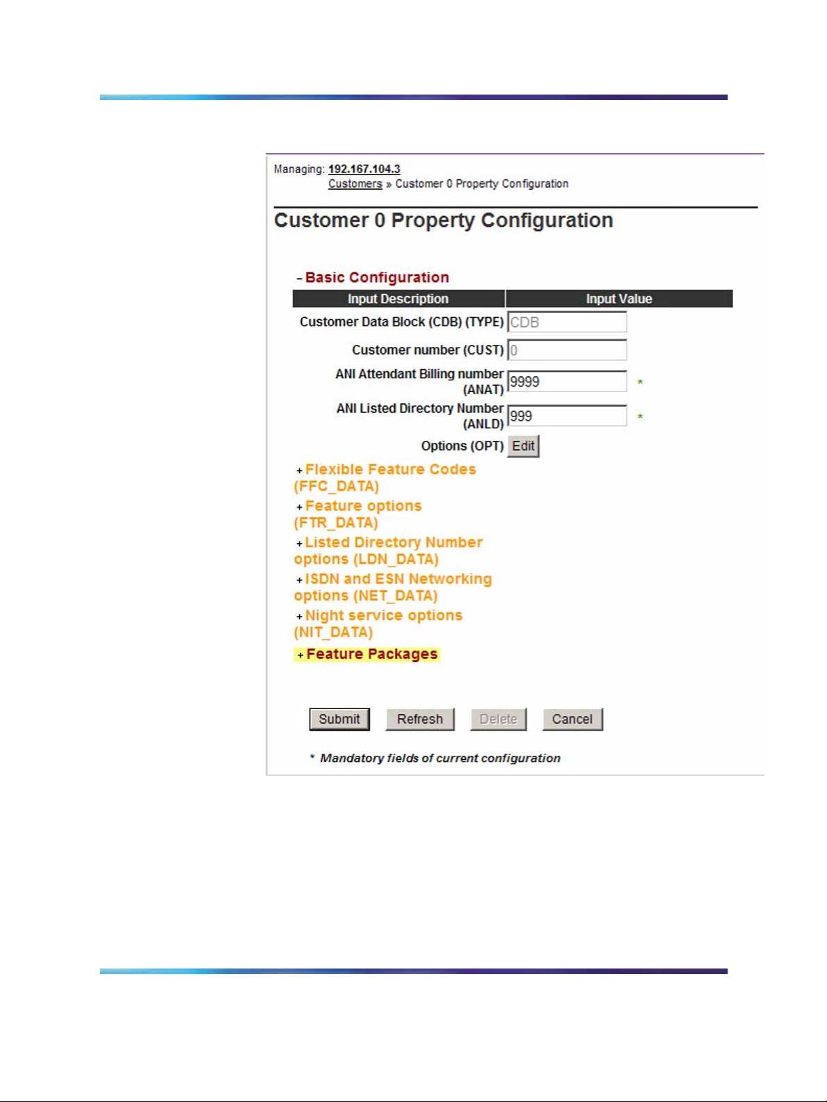
Figure 3
Customer Property Configuration
IP Peer Networking configuration 27
4
5
Expand the Feature Packages heading.
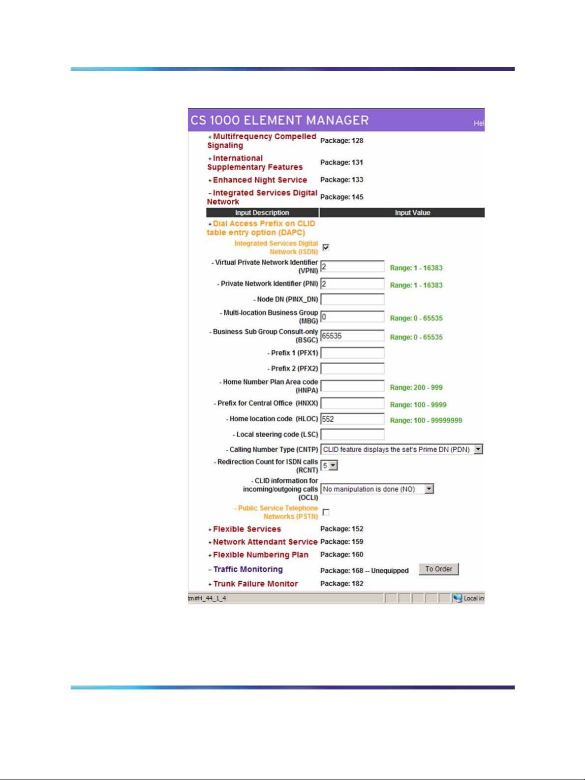
Scroll down and expand the Integrated Services Digital Network
Package 145 heading.
See Figure 4 "Integrated Services Digital Network Package 145"
(page 28).
Solution Integration Guide for Communication Server 1000/Multimedia Communication Server 5100
Copyright © 2006, Nortel Networks Nortel Networks Confidential
.
Enterprise: Common
NN49000-301 01.01 Standard
Release 4.5 27 October 2006
Page 28
28 IP Peer Networking and Call Server configuration
Figure 4
Integrated Services Digital Network Package 145
6
7
8
Solution Integration Guide for Communication Server 1000/Multimedia Communication Server 5100
Copyright © 2006, Nortel Networks Nortel Networks Confidential
.
Select the Integrated Services Digital Network (ISDN) check box.
Type a Private Network Identifier (PNI).
Type a Home Location Code (HLOC) if it is not already present.
Enterprise: Common
NN49000-301 01.01 Standard
Release 4.5 27 October 2006
Page 29

IP Peer Networking configuration 29
9
Click Submit.
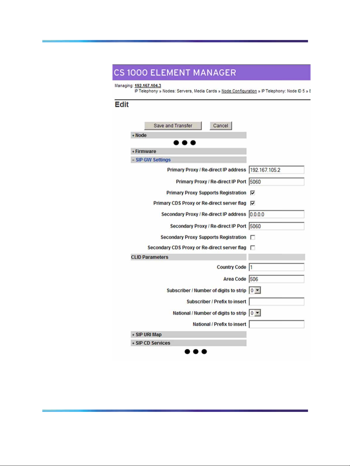
Configuring the SIP Gateway
Before you configure the SIP Gateway, check which route is configured as a
SIP route in LD 16. You must configure this route later.
Configuring the SIP Gateway
Step Action
1
2
3
4
5
Log on to Element Manager.
Select IP Telephony > Nodes: Servers, Media Cards >
Configuration.
Expand the Node.
Click Edit.
Expand the SIP GW Settings heading.
See Figure 5 "Edit SIP GW settings" (page 30).
—End—
Solution Integration Guide for Communication Server 1000/Multimedia Communication Server 5100
Copyright © 2006, Nortel Networks Nortel Networks Confidential
.
Enterprise: Common
NN49000-301 01.01 Standard
Release 4.5 27 October 2006
Page 30
30 IP Peer Networking and Call Server configuration
Figure 5
Edit SIP GW settings
6
7
Type the Primary Proxy/Re-direct IP address.
For Primary Proxy/Re-direct IP Port, use the default port value
of 5060.
Solution Integration Guide for Communication Server 1000/Multimedia Communication Server 5100
Copyright © 2006, Nortel Networks Nortel Networks Confidential
.
Enterprise: Common
NN49000-301 01.01 Standard
Release 4.5 27 October 2006
Page 31

IP Peer Networking configuration 31
You can use the T-LAN IP Address of the Alternate NRS in the
Secondary Proxy/Re-direct IP address field.
8
Select the Primary Proxy Supports Registration check box.
—End—
Enabling the SIP Virtual Trunk application
Perform the following procedure to enable SIP functionality in Element
Manager. You must reboot the system during this procedure.
Enabling the SIP Virtual Trunk application
Step Action
1
2
Log on to Element Manager.
Select IP Telephony > Nodes: Servers, Media Cards >
Configuration.
See Figure 6 "Node Configuration" (page 31).
Figure 6
Node Configuration
3
4
5
Solution Integration Guide for Communication Server 1000/Multimedia Communication Server 5100
Copyright © 2006, Nortel Networks Nortel Networks Confidential
.
Expand the Node heading.
Click Edit.
Expand the Signaling Servers heading.
Enterprise: Common
NN49000-301 01.01 Standard
Release 4.5 27 October 2006
Page 32

32 IP Peer Networking and Call Server configuration
6
Expand the Signaling Server Properties heading.
See Figure 7 "H323 Gateway and Signaling Server" (page 32).
Figure 7
H323 Gateway and Signaling Server
7
For Enable IP Peer Gateway (Virtual Trunk TPS), select a SIP
option (SIP only or H.323 and SIP).
8 Select the Enable SIP Proxy/Redirect Server check box.
Solution Integration Guide for Communication Server 1000/Multimedia Communication Server 5100
Copyright © 2006, Nortel Networks Nortel Networks Confidential
.
Enterprise: Common
NN49000-301 01.01 Standard
Release 4.5 27 October 2006
Page 33

IP Peer Networking configuration 33
9
10
11
12
13
For SIP Transport Protocol, select UDP.
TCP is the default. UDP means User Datagram Protocol in this
instance.
Verify the Local SIP Port.
The default is 5060.
Enter the SIP Domain Name.
The SIP Domain Name must be less than 128 characters in
length. Valid characters are a-z, 0-9, period, hyphen, comma, and
underscore.
This string builds all SIP messages and appears in the URI phone
context. If you enable the SIP Gateway application, specify this field.
This name must match the Service Domain name configured in NRS.
Enter the SIP Gateway Endpoint Name and Authentication
Password.
These values must match the data in NRS. The SIP Gateway
Endpoint Name becomes the Gateway’s user ID. The user ID and
password helps authenticate the Gateway with the MCS 5100 proxy
server if you configure Converged Desktop.
Select the Enable Gatekeeper check box.
14
15
16
17
18
19
For Network Routing Service Role, select Primary, Alternate,
or Failsafe.
Click Save and Transfer.
A message appears prompting you to reboot the system.
Click OK.
When a successful transfer message appears, indicating that the
system is done transferring data, click OK.
Select IP Telephony > Nodes:Server,Media Cards > Maintenance
and Reports.
Expand the Node ID.
See Figure 8 "Node Maintenance and Reports" (page 34).
Solution Integration Guide for Communication Server 1000/Multimedia Communication Server 5100
Copyright © 2006, Nortel Networks Nortel Networks Confidential
.
Enterprise: Common
NN49000-301 01.01 Standard
Release 4.5 27 October 2006
Page 34

34 IP Peer Networking and Call Server configuration
Figure 8
Node Maintenance and Reports
20
21
Click Reset.
Click OK.
—End—
Configuring the SIP Redirect Server and URI map
Use this procedure to configure your SIP numbering plan mapping. You
can use this mapping to interpret TON/NPI numbers and map them to the
associated context (to or from SIP). The TON/NPI field explicitly maps to the
SIP phone-context attribute in the URI address.
Configuring the SIP Redirect Server and URI map
Step Action
1
2
3 Expand the SIP URI Map heading.
Log on to Element Manager.
Select IP Telephony > Nodes:Servers, Media Cards >
Configuration.
See Figure 9 "Edit SIP URI Map" (page 35).
Solution Integration Guide for Communication Server 1000/Multimedia Communication Server 5100
Copyright © 2006, Nortel Networks Nortel Networks Confidential
.
Enterprise: Common
NN49000-301 01.01 Standard
Release 4.5 27 October 2006
Page 35

Figure 9
Edit SIP URI Map
IP Peer Networking configuration 35
4
5
In the Private/UDP domain name field, type the L1 domain.
In the Private/CDP domain name field, type the L0 and L1 domains
in the format <L0 domain.L1 domain>.
6
Enter the values for your SIP numbering plan in the appropriate
fields.
7
Solution Integration Guide for Communication Server 1000/Multimedia Communication Server 5100
Copyright © 2006, Nortel Networks Nortel Networks Confidential
.
Click Save and Transfer.
Enterprise: Common
NN49000-301 01.01 Standard
Release 4.5 27 October 2006
Page 36

36 IP Peer Networking and Call Server configuration
8
Click OK when the system is done transferring data and the
successful transfer message appears.
Creating the virtual D-channel
Perform the following procedure to create the virtual D-channel.
Creating the virtual D-channel
Step Action
1
2
Log on to Element Manager.
Select Routes and Trunks > D-Channels.
The D-Channels page appears. See Figure 10 "D-Channels" (page
36).
A message appears if a D-channel is not configured. Click OK.
Figure 10
D-Channels
—End—
3
From the Choose a D-Channel Number menu, select the
D-Channel number.
Solution Integration Guide for Communication Server 1000/Multimedia Communication Server 5100
Copyright © 2006, Nortel Networks Nortel Networks Confidential
.
Enterprise: Common
NN49000-301 01.01 Standard
Release 4.5 27 October 2006
Page 37

IP Peer Networking configuration 37
D-channels 0,1, and 2 are usually used or shared with other
applications. It is recommended that you begin configuring virtual
D-channels on channel 3.
4
5
From the Type menu, select the D-Channel type.
Click to Add.
The D-Channels Property Configuration page appears. See Figure
11 "D-Channels Property Configuration" (page 37).
Figure 11
D-Channels Property Configuration
6
For the D Channel Card Type (CTYP), select D-channel is over
IP (DCIP).
7
Solution Integration Guide for Communication Server 1000/Multimedia Communication Server 5100
Copyright © 2006, Nortel Networks Nortel Networks Confidential
.
For the Designator (DES), type a meaningful name.
Enterprise: Common
NN49000-301 01.01 Standard
Release 4.5 27 October 2006
Page 38

38 IP Peer Networking and Call Server configuration
The Designator must not contain spaces; use underscores instead.
Make a note of the Designator in your records for future reference.
8
For User (USR), select Integrated Services Signaling Link
Dedicated (ISLD).
9
For Interface type for D-channel (IFC), select Meridian Meridian1
(SL1).
10
Leave all other parameters as is and click Submit.
The new channel appears.
Configuring zones (LD 117)
Before you can configure the virtual routes and trunks, the following zones
must be configured, in any order:
•
Zone 1 = IP Phones zone (ZBRN = MO)
•
Zone 2 = Voice Gateway Channels zone, which should be different from
the IP Phones zone (ZBRN = VTRK)
Ensure that enough bandwidth is allocated for the zones with the heaviest
traffic.
Never use or configure zone 0.
—End—
Configuring zones (LD 117)
Step Action
1
2
Solution Integration Guide for Communication Server 1000/Multimedia Communication Server 5100
Copyright © 2006, Nortel Networks Nortel Networks Confidential
.
Log on to Element Manager.
Select IP Telephony > Zones.
See Figure 12 "Zones" (page 39).
Enterprise: Common
NN49000-301 01.01 Standard
Release 4.5 27 October 2006
Page 39

Figure 12
Zones
IP Peer Networking configuration 39
3
Select the Zone you wish to configure.
Configured zones appear in the list at the bottom of the page.
4
Click to Add.
The Zone Basic Property and Bandwidth Management page
appears. See Figure 13 "Zone Basic Property and Bandwidth
Management" (page 40).
5
After you click to Add, a message may appear prompting you to use
the Zone Basic Property and Bandwidth Management Spreadsheet.
Click OK.
Solution Integration Guide for Communication Server 1000/Multimedia Communication Server 5100
Copyright © 2006, Nortel Networks Nortel Networks Confidential
.
Enterprise: Common
NN49000-301 01.01 Standard
Release 4.5 27 October 2006
Page 40

40 IP Peer Networking and Call Server configuration
Figure 13
Zone Basic Property and Bandwidth Management
6
7
Leave the default values for bandwidth and resource type as is.
Set the Zone Intent (ZBRN) as follows:
•
Zone 1 is for the IP Phones at the Main Office. Set Zone Intent
(ZBRN) for Zone 1 to MO.
•
Zone 2 is for the Voice Gateway Channels. Set Zone Intent
(ZBRN) for Zone 2 to VTRK.
8
9
10
For Description (ZDES), type a meaningful description.
Click Submit.
Repeat this procedure for the second zone.
—End—
Solution Integration Guide for Communication Server 1000/Multimedia Communication Server 5100
Copyright © 2006, Nortel Networks Nortel Networks Confidential
.
Enterprise: Common
NN49000-301 01.01 Standard
Release 4.5 27 October 2006
Page 41

Creating the virtual route (LD 16)
Perform the following procedure to create the virtual route.
Creating the virtual route (LD 16)
Step Action
IP Peer Networking configuration 41
1
2
Log on to Element Manager.
Select Routes and Trunks > Routes and Trunks.
3 Click the Add route button.
The New Route Configuration page appears. See Figure 14 "New
Route Configuration" (page 42).
Solution Integration Guide for Communication Server 1000/Multimedia Communication Server 5100
Copyright © 2006, Nortel Networks Nortel Networks Confidential
.
Enterprise: Common
NN49000-301 01.01 Standard
Release 4.5 27 October 2006
Page 42

42 IP Peer Networking and Call Server configuration
Figure 14
New Route Configuration
4
5
6
Solution Integration Guide for Communication Server 1000/Multimedia Communication Server 5100
Copyright © 2006, Nortel Networks Nortel Networks Confidential
.
Select the Route Number (ROUT).
For Designator field for trunk (DES), type a meaningful name.
For Trunk Type (TKTP), select TIE Trunk data block (TIE).
Enterprise: Common
NN49000-301 01.01 Standard
Release 4.5 27 October 2006
Page 43

IP Peer Networking configuration 43
7
8
9
10
11
12
13
14
15
For Incoming and Outgoing trunk (ICOG), select Incoming and
Outgoing (IAO).
Set the Access Code for the trunk route (ACOD).
Select the The route is for a virtual trunk route (VTRK) check box.
Type the Zone number of the zone with the ZBRN set to Vtrk for
the new route.
This value must match the values you configure in the Signaling
Server.
Type the Node ID of signaling server of this route (NODE).
This value must match the values you configure in the Signaling
Server.
For Protocol ID for the route (PCID), select SIP H323.
Select the Integrated Services Digital Network option (ISDN)
check box.
For Mode of operation (MODE), select Route uses ISDN
Signaling Link (ISLD).
Select the virtual D-Channel number (DCH).
16
17
18
For Interface type for route (IFC), select Meridian M1 (SL1).
Type the Private Network Identifier (PNI).
Leave the Call type for outgoing direct dialed TIE route (CTYP)
at the default value.
It is best to let NARS/BARS entries determine the NPI/TON for a
number so that the route can be used for multiple call types.
19
20
Select the Insert ESN Access Code (INAC) check box.
Leave the other default values as is and click Submit.
The Routes and Trunks screen appears showing the created routes.
Creating the virtual trunks (LD 14)
The Virtual Trunk TNs that you configure in this procedure cannot overlap
with the ones that you configure for IP Phones.
—End—
Solution Integration Guide for Communication Server 1000/Multimedia Communication Server 5100
Copyright © 2006, Nortel Networks Nortel Networks Confidential
.
Enterprise: Common
NN49000-301 01.01 Standard
Release 4.5 27 October 2006
Page 44

44 IP Peer Networking and Call Server configuration
Creating the virtual trunks (LD 14)
Step Action
1
2
Log on to Element Manager.
Select Routes and Trunks > Routes and Trunks.
See Routes and Trunks.
3
4
Expand the Customer heading.
Click Add trunk next to the route to which you wish to add the trunk.
The New Trunk Configuration page appears. See Figure 15 "New
Trunk Configuration" (page 44).
Figure 15
New Trunk Configuration
5
If you are configuring several trunks the same way, select the
Multiple trunk input number (MTINPUT) (optional).
Solution Integration Guide for Communication Server 1000/Multimedia Communication Server 5100
Copyright © 2006, Nortel Networks Nortel Networks Confidential
.
Enterprise: Common
NN49000-301 01.01 Standard
Release 4.5 27 October 2006
Page 45

IP Peer Networking configuration 45
6
7
For Trunk data block (TYPE), select IP Trunk (IPTI).
Type the Terminal Number (TN) for the trunk.
8 For Designator field for trunk (DES), type a meaningful value.
9
10
11
For Extended Trunk (XTRK), select Virtual trunk (VTRK).
Type the Route number, Member number (RTMB)for the trunk.
Set the values of Start arrangement Incoming (STRI) and Start
arrangement Outgoing (STRO).
Immediate (IMM) is recommended for both fields.
12
13
Type the Channel ID for this trunk (CHID).
You can add a Class of Service (CLS) for all features that you wish.
In a basic configuration, you can leave the CLS as is.
14
Select Advanced Trunk Configurations to display a list of
advanced features.
15
16
Edit the necessary fields or accept the default values.
Click Submit.
—End—
Creating the Network Control Block (NCTL) for network access (LD 87)
Complete the following procedure to create the Network Control Block.
Creating the Network Control Block (NCTL) for network access
(LD 87)
Step Action
1 Log onto Element Manager.
2
3
4
5
Select Open Dialing and Numbering Plans > Electronic Switched
Networks.
Expand the Customer tab.
See Figure 17 "Electronic Switched Network (ESN)" (page 47).
Select Network Control and Services > Network Control
Parameter (NTCL).
A message appears if no network control data is configured. Click
OK to configure new data.
Next to Network Control Basic Parameters, click the Edit tab.
Solution Integration Guide for Communication Server 1000/Multimedia Communication Server 5100
Copyright © 2006, Nortel Networks Nortel Networks Confidential
.
Enterprise: Common
NN49000-301 01.01 Standard
Release 4.5 27 October 2006
Page 46

46 IP Peer Networking and Call Server configuration
The Network Control Basic Parameters page appears. See Figure
16 "Network Control Basic Parameters" (page 46).
Figure 16
Network Control Basic Parameters
6
7
Choose the basic control parameters for your network.
Click Submit.
Creating the ESN data block for CDP
Complete the following procedure to create the ESN data block for CDP.
Creating the ESN data block for CDP
Step Action
1
2
3
Log on to Element Manager.
Select Dialing and Numbering Plans > Electronic Switched
Network.
Expand the Customer heading.
See Figure 17 "Electronic Switched Network (ESN)" (page 47).
—End—
Solution Integration Guide for Communication Server 1000/Multimedia Communication Server 5100
Copyright © 2006, Nortel Networks Nortel Networks Confidential
.
Enterprise: Common
NN49000-301 01.01 Standard
Release 4.5 27 October 2006
Page 47

Figure 17
Electronic Switched Network (ESN)
IP Peer Networking configuration 47
4
Select Network Control & Services > ESN Access Codes and
Parameters (ESN).
5
A message appears if ESN data is not configured. Click OK.
The ESN Access Codes and Basic Parameters page appears. See
Figure 18 "ESN Access Codes and Basic Parameters" (page 48).
If ESN data is configured on your switch, the fields on this page
appear populated.
Solution Integration Guide for Communication Server 1000/Multimedia Communication Server 5100
Copyright © 2006, Nortel Networks Nortel Networks Confidential
.
Enterprise: Common
NN49000-301 01.01 Standard
Release 4.5 27 October 2006
Page 48

48 IP Peer Networking and Call Server configuration
Figure 18
ESN Access Codes and Basic Parameters
6
Edit the main parameters (MXDM, MXRL, MXSD, MXIX, MXFC,
MXFS and MXLC) if required, or leave the default values as is.
7
Select the Coordinated dialing Plan feature for this customer
(CDP) check box.
8
9
Set the value of the Maximum number of Steering Codes (MXSC).
Set the value of the Number of digits in CDP DN (DSC+DN or
LSC+DN) (NCDP).
Solution Integration Guide for Communication Server 1000/Multimedia Communication Server 5100
Copyright © 2006, Nortel Networks Nortel Networks Confidential
.
Enterprise: Common
NN49000-301 01.01 Standard
Release 4.5 27 October 2006
Page 49

IP Peer Networking configuration 49
10
Click Submit.
—End—
Creating the RLB for the virtual trunk route (LD 86)
Perform the following procedure to create the RLB for the virtual trunk route.
Creating the RLB for the virtual trunk route (LD 86)
Step Action
1
2
3
4
Log on to Element Manager.
Select Dialing and Numbering Plans > Electronic Switched
Networks.
Expand the Customer heading.
See Figure 17 "Electronic Switched Network (ESN)" (page 47).
Select Network Control and Services > Route List Blocks (RLB).
If route list blocks are not configured, the error message “Route List
does not exist” appears. Click OK.
5
6
Type the Route List Index number.
Click to Add.
The Route List Block Configuration page appears. See Figure 19
"Route List Block" (page 50).
Solution Integration Guide for Communication Server 1000/Multimedia Communication Server 5100
Copyright © 2006, Nortel Networks Nortel Networks Confidential
.
Enterprise: Common
NN49000-301 01.01 Standard
Release 4.5 27 October 2006
Page 50

50 IP Peer Networking and Call Server configuration
Figure 19
Route List Block
7
8
9
Solution Integration Guide for Communication Server 1000/Multimedia Communication Server 5100
Copyright © 2006, Nortel Networks Nortel Networks Confidential
.
Select the Route Number (ROUT) you previously defined.
For Strategy on Congestion (SBOC), select Reroute All (RRA).
Accept the other defaults and click Submit.
Enterprise: Common
NN49000-301 01.01 Standard
Release 4.5 27 October 2006
Page 51

The new Route List Block is generated. You can check the
configuration by selecting Route List Block Index and Data Entry
Index.
—End—
Creating the CDP steering codes (LD 87)
Perform the following procedure to create the CDP steering codes.
Creating the CDP steering codes (LD 87)
Step Action
IP Peer Networking configuration 51
1
2
Log on to Element Manager.
Select Dialing and Numbering Plans > Electronic Switched
Network.
3
Expand the Customer heading.
See Figure 17 "Electronic Switched Network (ESN)" (page 47).
4
Select Coordinated Dialing Plan (CDP) > Distant Steering Code
List.
5
Enter the Distant Steering Code (DSC).
This is the DN range of other systems on the network. You can add
more steering codes in this manner.
6
Click to Add.
The Distant Steering Code page appears. See Figure 20 "Distant
Steering Code" (page 52).
Solution Integration Guide for Communication Server 1000/Multimedia Communication Server 5100
Copyright © 2006, Nortel Networks Nortel Networks Confidential
.
Enterprise: Common
NN49000-301 01.01 Standard
Release 4.5 27 October 2006
Page 52

52 IP Peer Networking and Call Server configuration
Figure 20
Distant Steering Code
7
8
9
10
11
Check the populated fields.
Select a Route list to be accessed for trunk steering code (RLI).
Click Submit.
Repeat steps 6 to 9 for all other call types on your network:
•
LOC (Location Code)
• HLOC (Home Location Code)
•
NPA
•
HNPA (Home NPA)
• SPN (Special Numbers)
•
NXX
This steering code is now defined. You can click the plus sign to
view all the entered information.
—End—
Solution Integration Guide for Communication Server 1000/Multimedia Communication Server 5100
Copyright © 2006, Nortel Networks Nortel Networks Confidential
.
Enterprise: Common
NN49000-301 01.01 Standard
Release 4.5 27 October 2006
Page 53

Checking CODEC and QoS settings
At this point, the Call Server configuration is complete. It is recommended
that you check the CODEC and QoS settings.
Checking CODEC and QoS settings
Step Action
IP Peer Networking configuration 53
1
2
Log on to Element Manager.
Select IP Telephony Manager > Nodes: Servers, Media Cards >
Configuration.
See Figure 6 "Node Configuration" (page 31).
3
4
Expand the Node heading.
Click Edit.
The Edit page appears. See Figure 21 "Node Editing" (page 54).
Solution Integration Guide for Communication Server 1000/Multimedia Communication Server 5100
Copyright © 2006, Nortel Networks Nortel Networks Confidential
.
Enterprise: Common
NN49000-301 01.01 Standard
Release 4.5 27 October 2006
Page 54

54 IP Peer Networking and Call Server configuration
Figure 21
Node Editing
5
Expand the VGW and IP phone CODEC profile heading and edit
the fields as necessary.
6
Solution Integration Guide for Communication Server 1000/Multimedia Communication Server 5100
Copyright © 2006, Nortel Networks Nortel Networks Confidential
.
Expand the QoS heading and edit the fields as necessary.
Enterprise: Common
NN49000-301 01.01 Standard
Release 4.5 27 October 2006
Page 55

Call Server configuration 55
7
If you make configuration changes, click Save and Transfer;
otherwise, click Cancel.
Call Server configuration
The procedures in this section are as follows:
•
"Configuring Application Module Link (LD 17)" (page 55)
•
"Configuring Value Added Server (LD 17)" (page 56)
•
"Configuring the Automatic Call Distribution Directory Number (LD 23)"
(page 57)
•
"Configuring a Control Directory Number (LD 23)" (page 58)
•
"Configuring Service DN for Converged Desktop (LD 90)" (page 59)
•
"Configuring Personal Call Assistant (LD 11)" (page 60)
•
"Configuring the Signaling Server" (page 62)
•
"Configuring Converged Desktop users (LDs 10/11)" (page 67)
—End—
Configuring Application Module Link (LD 17)
Perform the following procedure to configure Application Module Link.
Configuring Application Module Link (LD 17)
Step Action
1
2
3 Enter the appropriate values as described in the following table.
Table 3
LD 17 — Application Module Link
Prompt Response Description
REQ CHG Change existing data
TYPE ADAN Action Device and Number
Connect to the Call Server.
Enter LD 17.
For prompts not listed in the following table, press Enter to accept
the default.
—End—
Solution Integration Guide for Communication Server 1000/Multimedia Communication Server 5100
Copyright © 2006, Nortel Networks Nortel Networks Confidential
.
Enterprise: Common
NN49000-301 01.01 Standard
Release 4.5 27 October 2006
Page 56

56 IP Peer Networking and Call Server configuration
Prompt Response Description
- ADAN NEW ELAN x Action Device and Number, where x is
the ELAN Link number.
x = 32 to 47 (inclusive) for Small
Systems
x = 32 to 127 (inclusive) for Large
Systems
AML link number within the preceding
range implies that the transport is over
TCP/RUDP link.
CTYP ELAN AML over Ethernet card type
Configuring Value Added Server (LD 17)
Perform the following procedure to configure the Value Added Server.
Configuring Value Added Server (LD 17)
Step Action
1
2
3
Connect to the Call Server.
Enter LD 17.
Enter the appropriate values as described in the following table.
For prompts not listed in the following table, press Enter to accept
the default.
—End—
Table 4
LD 17 — Value Added Server
Prompt Response Description
REQ CHG Change existing data
TYPE VAS Value Added Server (VAS) configuration
VAS NEW New VAS data block
Solution Integration Guide for Communication Server 1000/Multimedia Communication Server 5100
Copyright © 2006, Nortel Networks Nortel Networks Confidential
.
Enterprise: Common
NN49000-301 01.01 Standard
Release 4.5 27 October 2006
Page 57

Prompt Response Description
VSID
ELAN
32–500
32–47
32–127
x
VAS identifier
For Small Systems and CS 1000S
For Large Systems
Nortel recommends that the VAS
identifier match the ELAN link number
configured in the procedure "Configuring
Application Module Link (LD 17)" (page
55).
Associate VAS ID x with Application
Module Link over Ethernet (ELAN) x
The AML ELAN link number must match
the number provisioned in the procedure
"Configuring Application Module Link
(LD 17)" (page 55).
Configuring the Automatic Call Distribution Directory Number (LD 23)
Perform the following procedure to configure the Automatic Call Distribution
Directory Number (ACD DN).
Call Server configuration 57
Configuring the Automatic Call Distribution Directory Number
(LD 23)
Step Action
1
2 Enter LD 23.
3
Table 5
LD 23 — ACD DN
Prompt Response Description
REQ NEW Add new data
Connect to the Call Server.
Enter the appropriate values as described in the following table.
For prompts not listed in the following table, press Enter to accept
the default.
—End—
Solution Integration Guide for Communication Server 1000/Multimedia Communication Server 5100
Copyright © 2006, Nortel Networks Nortel Networks Confidential
.
Enterprise: Common
NN49000-301 01.01 Standard
Release 4.5 27 October 2006
Page 58

58 IP Peer Networking and Call Server configuration
Prompt Response Description
TYPE ACD Automatic Call Distribution DN data
block
This is a special DN created to specify a
destination ACD DN to which incoming
calls are directed. Multiple CDNs
can direct calls to the same ACD DN,
providing different treatments based on
the CDN parameters.
CUST
ACDN
MAXP Maximum number of agent positions
xx
xxxx
Customer number as defined in LD 15
(customer number associated with this
data block)
ACD Directory Number, where xxxx =
the DN for your system
Configuring a Control Directory Number (LD 23)
Perform the following procedure to configure a Control Directory Number
(CDN).
Configuring a Control Directory Number (LD 23)
Step Action
1
2
3
Table 6
LD 23 — CDN
Prompt Response Description
REQ NEW Add new data
TYPE CDN Control DN data block
CUST
xx
Connect to the Call Server.
Enter LD 23.
Enter the appropriate values as described in the following table.
For prompts not listed in the following table, press Enter to accept
the default.
—End—
Customer number associated with this
data block
Solution Integration Guide for Communication Server 1000/Multimedia Communication Server 5100
Copyright © 2006, Nortel Networks Nortel Networks Confidential
.
Enterprise: Common
NN49000-301 01.01 Standard
Release 4.5 27 October 2006
Page 59

Call Server configuration 59
Prompt Response Description
CDN
CDSQ YES Converged Desktop Service Queue
DFDN
xxxx
x...x
Control DN
The CDN cannot be configured as a
mailbox DN.
YES = allow CDSQ
NO = deny CDSQ
For Converged Desktop, set CDSQ to
YES.
Local Default ACD DN
Up to 4 digits, or up to 7 digits with
Directory Number Expansion (DNXP)
package 150.
IMPORTANT: The local default ACD
DN must match ACDN configured in the
procedure "Configuring the Automatic
Call Distribution Directory Number (LD
23)" (page 57).
CNTL YES Control DN is in control
When CNTL = NO, CDN calls are sent
to the Default ACD DN (DFDN)
Configuring Service DN for Converged Desktop (LD 90)
Perform the following procedure to configure the Service DN for Converged
Desktop.
Configuring Service DN for Converged Desktop (LD 90)
Step Action
1
2
3
Connect to the Call Server.
Enter LD 90.
Enter the appropriate values as described in the following table.
For prompts not listed in the following table, press Enter to accept
the default.
—End—
Solution Integration Guide for Communication Server 1000/Multimedia Communication Server 5100
Copyright © 2006, Nortel Networks Nortel Networks Confidential
.
Enterprise: Common
NN49000-301 01.01 Standard
Release 4.5 27 October 2006
Page 60

60 IP Peer Networking and Call Server configuration
Table 7
LD 90 — Service DN for Converged Desktop
Prompt Response Description
REQ NEW Add new data
CUST
xx
Customer number as defined in LD 15
FEAT NET Network translation tables
TRAN AC1 or AC2 Access Code, where:
AC1 = NARS / BARS
AC2 = NARS
TYPE SPN Special number translation (special
code translation block)
Configure the CDS Service DN as an
SPN, and point it to the SIP trunk. This
number is internal only between the
Call Server and the Signaling Server for
reserving the Virtual Trunk when routing
the terminating CD call out to the MCS
5100.
SPN
xxxx
Special Number
The same DN must be used on the
Signaling Server in the Service DN field
of the config.ini file.
-FLEN
xx
Flexible length number of digits Flexible
length is the exact number number of
digits the system expects to receive
before accessing a trunk and outpulsing
those digits.
-RLI
xxx
Route List Index for Converged Desktop
Service Class of Service (CLS)
The RLI number must point to the SIP
Virtual Trunk on the desired Signaling
Sever. For example, if the CDN and
SPN are configured on Signaling Server
1, then this RLI must use the route
configured on Signaling Server 1.
Configuring Personal Call Assistant (LD 11)
Perform the following procedure to configure Personal Call Assistant (PCA).
Configure a minimum of two PCAs. Configure the number of PCA agents
appropriate for your system’s call volume.
Solution Integration Guide for Communication Server 1000/Multimedia Communication Server 5100
Copyright © 2006, Nortel Networks Nortel Networks Confidential
.
Enterprise: Common
NN49000-301 01.01 Standard
Release 4.5 27 October 2006
Page 61

Call Server configuration 61
Configuring Personal Call Assistant (LD 11)
Step Action
1
2
3
Connect to the Call Server.
Enter LD 11.
Enter the appropriate values as described in the following table.
For prompts not listed in the following table, press Enter to accept
the default.
—End—
Table 8
LD 11 — PCA
Prompt Response Description
REQ NEW Add a new data block to the system
TYPE PCA Personal Call Assistant
TN
DES
CUST
ZONE
lscu
cu
aaaaaa
xx
xx
PCA Terminal Number
For Large Systems and CS 1000E
systems, where l = loop, s = shelf, c =
card, u = unit
For Small Systems, CS 1000S systems,
Media Gateway 1000B systems, and
Media Gateway 1000T systems, where
c = card, u = unit
Description of PCA Terminal Number
Customer number as defined in LD 15
Zone number for IP Phones
CLS UNR Unrestricted Class of Service
KEY
Solution Integration Guide for Communication Server 1000/Multimedia Communication Server 5100
Copyright © 2006, Nortel Networks Nortel Networks Confidential
.
0 ACD yyyy cccc zzzz
2 MCN yyyy
NN49000-301 01.01 Standard
Release 4.5 27 October 2006
Telephone function key assignments
Automatic Call distribution (ACD) key,
where:
yyyy = ACD DN configured in LD 23 for
Converged Desktop use
ccc = CLID table entry of (0)–N, where N
= the value entered at the SIZE prompt
of LD 15 minus 1
zzzz = agent’s position ID (zzzz can
be up to 4 digits; up to 7 digits with
Directory Number Expansion [DNXP]
package 150)
Enterprise: Common
Page 62

62 IP Peer Networking and Call Server configuration
Prompt Response Description
Multiple Call Non-Ringing key, where
yyyy = Converged telephone Call
Forward DN
The DN can be up to 4 digits, or up to 7
digits with DNxP. When the MCN key
is defined, the MARP prompt appears.
Because MCN and DN are used by the
feature to originate calls, the same DN
can be applied to all PCAs.
Configuring the Signaling Server
Perform the following procedure to configure the Signaling Server.
Configuring the Signaling Server
Step Action
1
2
Log on to Element Manager.
Select IP Telephony > Nodes: Servers, Media Cards >
Configuration.
3
4
Beside the node for which SIP CDS is to be configured, click Edit.
Expand the SIP CD Services heading.
See Figure 22 "SIP CD Services" (page 63).
Solution Integration Guide for Communication Server 1000/Multimedia Communication Server 5100
Copyright © 2006, Nortel Networks Nortel Networks Confidential
.
Enterprise: Common
NN49000-301 01.01 Standard
Release 4.5 27 October 2006
Page 63

Figure 22 SIP CD Services
Call Server configuration 63
5
Fill in the appropriate values for your network.
Refer to Table 9 "SIP CD Services — fields description" (page 63)
for configuration parameters.
Table 9
SIP CD Services — fields description
Parameter Value Description
Service enabled
Solution Integration Guide for Communication Server 1000/Multimedia Communication Server 5100
Copyright © 2006, Nortel Networks Nortel Networks Confidential
.
<check box> To enable the Converged Desktop Service
(CDS) application for this node, select this
check box.
If CDS is not enabled, no calls are sent to
the MCS 5100, including both originating and
terminating calls to or from the Converged
Desktop telephone.
Enterprise: Common
NN49000-301 01.01 Standard
Release 4.5 27 October 2006
Page 64

64 IP Peer Networking and Call Server configuration
Parameter Value Description
Service DN used for making
VTRK call from agent:
Converged Telephone Call
Forward DN
User Info. field for Invite
message on the Converged
Desktop MO Set
Enter the Service DN. The Service DN is a
number for the CS 1000 to call the Signaling
Server CDS application over a SIP Virtual
Trunk. This number can be composed of:
LOC + extension
Extension
SPN
This field is required if the SIP gateway
application is enabled and the Converged
Desktop Service is used. The Converged
telephone call forward DN is the CDN defined
in LD 23 for the CDS application. This entry
designates the CDN that CDS acquires to
obtain messaging for call activity. The CS
1000 telephone with CDMO or CDMV Class
of Service redirects all calls to the CDN.
The acquisition of the CDN identified in this
field allows messaging for call activity to be
processed to the CDS application on the
Signaling Server.
This field is used in the INVITE message
of Converged Desktop terminating call
handling if the telephone is a multimedia-only
telephone.
Verify that this field appears as follows:
sip:convergeddesktop@SIPdomainname;
nortelconverged=continueforce
If this string does not appear as shown, then
the SIP domain name was not configured
during the SIP trunk Gateway configuration.
You can find the SIP domain name on the
Edit page under Signaling Server > Signaling
Server xxx.xxx.xxx.xxx Properties.
Solution Integration Guide for Communication Server 1000/Multimedia Communication Server 5100
Copyright © 2006, Nortel Networks Nortel Networks Confidential
.
Enterprise: Common
NN49000-301 01.01 Standard
Release 4.5 27 October 2006
Page 65

Parameter Value Description
Call Server configuration 65
User Info. field for Invite
message on the Converged
Desktop MV Set:
User Info. field in the notify
message for Converged
Desktop:
This field is used in the INVITE message for
Converged Desktop terminating call handling
if the telephone is both a multimedia and a
voice telephone.
Verify that this field appears as follows:
sip:convergeddesktop@SIPdomainname;
nortelconverged=conditionalfork
If this string does not appear as shown, then
the SIP domain name was not configured
during the SIP trunk Gateway configuration.
You can find the SIP domain name on the
Edit page under Signaling Server > Signaling
Server xxx.xxx.xxx.xxx Properties.
This field is used in the NOTIFY message for
Converged Desktop.
Verify that this field appears as follows:
sip:convergeddesktop@SIPdomainname
If this string does not appear as shown, then
the SIP domain name was not configured
during the SIP trunk Gateway configuration.
You can find the SIP domain name on the
Edit page under Signaling Server > Signaling
Server xxx.xxx.xxx.xxx Properties.
RAN route for Announce:
0 to 511
Enter the Recorded Announcement (RAN)
route number for call announce as configured
in LD 16:
0–127 for Small Systems and CS 1000S
systems
0–511 for Large Systems
The RAN definition in this field can be used
in two distinct ways:
Call progress — A customer may want
to announce to a caller that their call is
proceeding and to please wait. RAN can
be used when delays may be longer than
expected as PCA makes calls to other
devices. If RAN is not used, callers hear a
ringback tone.
PCA busy — If PCA agents are busy
processing a call and the caller must wait for
a PCA so CDS can process the call, the user
can be directed to RAN.
Solution Integration Guide for Communication Server 1000/Multimedia Communication Server 5100
Copyright © 2006, Nortel Networks Nortel Networks Confidential
.
Enterprise: Common
NN49000-301 01.01 Standard
Release 4.5 27 October 2006
Page 66

66 IP Peer Networking and Call Server configuration
Parameter Value Description
Wait time before a caller is
sent to RAN Queue:
-1
0
<1 to 32767>
Enter the time (in seconds) that the caller
waits before the call is directed to the RAN
queue:
never send to RAN queue (default)
immediately send to RAN queue
wait n seconds before sending to RAN queue
Timeout for Ringing
indication of the CD set:
<5 to 60>
Enter the time to wait for ringing indication
on the Converged Desktop telephone. If a
timeout occurs, the system considers the
telephone as busy or call-forwarded to other
devices. As a result, the Converged Desktop
call is canceled. The timeout range is 5 to 60
seconds (default is 10 seconds).
Timeout for CD Server:
Timeout for call answered
by other than CD phone set:
<1 to 30>
Enter a timeout value. This value is used
when the MCS 5100 is not available or
there are network problems. An incoming
Converged Desktop call is terminated directly
to Converged Desktop telephone without
waiting for the MCS 5100. The timeout range
is 1 to 30 seconds (default is 5 seconds).
Note: Nortel recommends that the timeout
value not be configured as a small value. If
the time is too short, then a delayed packet
can eventually reach the MCS 5100. This
can cause a “race condition” between the
MCS 5100 routing the call and the CS 1000
routing the call. If the administrator knows of
a persistent network problem, or if the MCS
5100 is out of service for a period of time,
then Nortel recommends that you disable
Converged Desktop Service rather than
setting a small timeout value.
Enter a timeout value. If a call is answered on
any telephone (within the CS 1000 network)
other than Converged Desktop telephone
itself, then the SIP session is torn down
automatically after this timeout. The purpose
is to remove "lone" screen pop-ups on the
Converged Desktop PC Client (PCC). The
timeout range is 2 to 60 seconds (default is
2 seconds).
—End—
Solution Integration Guide for Communication Server 1000/Multimedia Communication Server 5100
Copyright © 2006, Nortel Networks Nortel Networks Confidential
.
Enterprise: Common
NN49000-301 01.01 Standard
Release 4.5 27 October 2006
Page 67

Call Server configuration 67
Configuring Converged Desktop users (LDs 10/11)
Perform the following procedure to configure Converged Desktop users.
Configuring Converged Desktop users (LDs 10/11)
Step Action
1
2
Connect to the Call Server.
To program analog (500/2500-type) telephones, enter LD 10.
3 To program digital telephones or IP Phones, enter LD 11.
4
Enter the appropriate values as described in the following table.
For prompts not listed in the following table, press Enter to accept
the default.
—End—
Table 10
LDs 10/11 — Converged Desktop users
Prompt Response Description
REQ NEW
CHG
TYPE
TN
a..a
lscu
cu
Add new data
Change existing data
Type of data block
PCA Terminal Number for sets
Format for Large Systems and CS
1000E systems, where l = loop, s =
shelf, c = card, u = unit
Format for Small Systems, CS1000S
systems, Media Gateway 1000B
systems, and Media Gateway 1000T
systems, where c = card, u = unit
CUST
ZONE
Solution Integration Guide for Communication Server 1000/Multimedia Communication Server 5100
Copyright © 2006, Nortel Networks Nortel Networks Confidential
.
xx
yy
Customer number as defined in LD 15
Zone for IP Phones
Enterprise: Common
NN49000-301 01.01 Standard
Release 4.5 27 October 2006
Page 68

68 IP Peer Networking and Call Server configuration
Prompt Response Description
CLS
CSDN Converged Desktop Service Control
(CDMR)
CDMV
CDMO
Converged Desktop Service Class of
Service (CLS):
Converged Desktop Multimedia
Restricted (default)
Converged Desktop Multimedia and
Voice
Converged Desktop Multimedia Only
Nortel recommends CDMV to give
users all features.
Directory Number (CDN) as configured
in LD 23.
CSDN is only prompted if CLS is
defined as CDMV or CDMO.
KEY
0 SCR yyyy
MCS 5100 configuration
The procedures in this section are as follows:
•
"Adding IP address of IP Telephony node to the application server as an
authenticated server" (page 69)
•
"Logging on to the MCS Provisioning Client" (page 70)
•
"Configuring the SIP Gateway, trunk, and trunk group" (page 71)
• "Configuring a new Gateway route" (page 72)
•
"Adding a trunk group directed to the Gateway route" (page 73)
Telephone function key assignments
Single Call Ringing key, where yyyy =
DN
The DN can be up to 4 digits, or up to 7
digits with Directory Number Expansion
(DNXP) package 150. Use a single
appearance DN to terminate Voice call
(VCC) or Signaling (SIG) calls. When
the SCR key is defined, the MARP
prompt appears.
•
"Configuring Number Qualifiers" (page 74)
• "Configuring Telephony Route Class of Service (COS)" (page 76)
•
"Configuring telephony routes for each dialing plan" (page 77)
•
"Configuring a new route list" (page 79)
Solution Integration Guide for Communication Server 1000/Multimedia Communication Server 5100
Copyright © 2006, Nortel Networks Nortel Networks Confidential
.
Enterprise: Common
NN49000-301 01.01 Standard
Release 4.5 27 October 2006
Page 69

MCS 5100 configuration 69
•
"Configuring the pretranslation table" (page 80)
Adding IP address of IP Telephony node to the application server as an authenticated server
Perform the following procedure to add the IP Telephony node to the
application server as an authenticated server.
Adding IP address of IP Telephony node to the application server
as an authenticated server
Step Action
1
2
3
4
5
6
7
8
9
From your Windows machine, select Start > MCP > Start console.
Log on using your user ID and password.
Expand the Sites folder.
Expand the site folder of interest (for example, MgmtSite).
Expand the Server folder.
Expand the app folder.
Expand the Components folder.
Right-click the appsvr and select Lock.
Right-click the appsvr again and click Modify.
The Modify window appears. See Figure 23 "Modify window" (page
70).
Solution Integration Guide for Communication Server 1000/Multimedia Communication Server 5100
Copyright © 2006, Nortel Networks Nortel Networks Confidential
.
Enterprise: Common
NN49000-301 01.01 Standard
Release 4.5 27 October 2006
Page 70

70 IP Peer Networking and Call Server configuration
Figure 23 Modify window
10
11
Click the Authentication tab.
For Authorized Node IP Address , enter the TLAN IP address of
the Signaling Server.
12
13
14
Click Add.
Click Apply.
From the MCP System Management Console, right-click the
appsvr.
15
Click Unlock.
—End—
Logging on to the MCS Provisioning Client
Perform the following procedure to log on to the MCS Provisioning Client.
Solution Integration Guide for Communication Server 1000/Multimedia Communication Server 5100
Copyright © 2006, Nortel Networks Nortel Networks Confidential
.
Enterprise: Common
NN49000-301 01.01 Standard
Release 4.5 27 October 2006
Page 71

Logging on to the MCS Provisioning Client
Step Action
MCS 5100 configuration 71
1
In a Web browser, enter the address of the MCS Provisioning Client
in the address bar.
The Provisioning Client login Web page appears. See Figure 24
"Provisioning Client Login page" (page 71).
Figure 24 Provisioning Client Login page
2
Log on using your user ID and password.
The default user ID and password are admin.
3
You can now begin provisioning the MCS 5100 system.
—End—
Configuring the SIP Gateway, trunk, and trunk group
Perform the following procedure to configure the SIP Gateway, trunk, and
trunk group.
Configuring the SIP Gateway, trunk, and trunk group
Step Action
1
2
3
Solution Integration Guide for Communication Server 1000/Multimedia Communication Server 5100
Copyright © 2006, Nortel Networks Nortel Networks Confidential
.
Log on to the MCS Provisioning Client.
Under the Provisioning folder, expand the Gateways folder.
Select Add Gateway.
The Update a gateway page appears. See Figure 25 "Update a
gateway" (page 72).
Enterprise: Common
NN49000-301 01.01 Standard
Release 4.5 27 October 2006
Page 72

72 IP Peer Networking and Call Server configuration
Figure 25 Update a gateway
4
For Gateway host, type the domain and Media Access Control
Address of the Gateway in the following format:
<domain name>:5060;maddr=<voice LAN node IP address>.
5 Select the Gateway type.
For integration with the CS 1000, set Gateway type to CS 1000.
6
For Location, select Other.
7 For Trusted Node, select True.
8
9
10
For Is Gateway, select True.
For Behind 1-to-1 NAT, select False.
Click Submit.
Configuring a new Gateway route
Perform the following procedure to configure a new Gateway route.
Configuring a new Gateway route
—End—
Step Action
1
2
Solution Integration Guide for Communication Server 1000/Multimedia Communication Server 5100
Copyright © 2006, Nortel Networks Nortel Networks Confidential
.
Log on to the MCS provisioning Client.
Under the Provisioning folder, expand the Gateways folder.
Enterprise: Common
NN49000-301 01.01 Standard
Release 4.5 27 October 2006
Page 73

MCS 5100 configuration 73
3
Click Add Route.
The Modify gateway route page appears. See Figure 26 "Modify
gateway route" (page 73).
Figure 26 Modify gateway route
4
For Route Name, type a description for the new route.
5
6
For Domain, select a domain to associate with the new route.
Click Save.
—End—
Adding a trunk group directed to the Gateway route
Perform the following procedure to add a trunk group directed to the
Gateway route.
Adding a trunk group directed to the Gateway route
Step Action
1
2
3 Click Add TrunkGroup. The Trunkgroup Provisioning page appears.
Log on to the MCS Provisioning Client.
Under the Provisioning folder, expand the Gateways folder.
See Figure 27 "Trunkgroup Provisioning" (page 74).
Solution Integration Guide for Communication Server 1000/Multimedia Communication Server 5100
Copyright © 2006, Nortel Networks Nortel Networks Confidential
.
Enterprise: Common
NN49000-301 01.01 Standard
Release 4.5 27 October 2006
Page 74

74 IP Peer Networking and Call Server configuration
Figure 27 Trunkgroup Provisioning
4
5
6
Select a Gateway.
Select a Route.
For Trunk Group, type a description for the new trunk group.
7 Click Save.
Configuring Number Qualifiers
Perform the following procedure to configure Number Qualifiers.
When you configure the Number Qualifiers, the information must match the
configured information for the CS 1000 SIP URI Map and the CS 1000 NRS
SIP URI. Refer to the procedure "Configuring the Signaling Server" (page
62) for more about the CS 1000 SIP URI Map configuration.
Configuring Number Qualifiers
Step Action
1
Log on to the MCS Provisioning Client.
—End—
2 Under the Provisioning folder, expand the Domains folder.
3
4
Solution Integration Guide for Communication Server 1000/Multimedia Communication Server 5100
Copyright © 2006, Nortel Networks Nortel Networks Confidential
.
Expand the folder for the domain that you are configuring.
Expand the Telephony Routes folder.
Enterprise: Common
NN49000-301 01.01 Standard
Release 4.5 27 October 2006
Page 75

MCS 5100 configuration 75
5
Select Number Qualifiers.
The Number Qualifiers page appears. See Figure 28 "Number
Qualifiers" (page 75).
Figure 28
Number Qualifiers
6
7
8
9
Add new number qualifiers for each entry in the SIP URI Map.
In the Name field, enter the Number Qualifier name.
In the Description field, enter a description of the Number Qualifier.
Click Add.
—End—
Solution Integration Guide for Communication Server 1000/Multimedia Communication Server 5100
Copyright © 2006, Nortel Networks Nortel Networks Confidential
.
Enterprise: Common
NN49000-301 01.01 Standard
Release 4.5 27 October 2006
Page 76

76 IP Peer Networking and Call Server configuration
Configuring Telephony Route Class of Service (COS)
Perform the following procedure to configure COS.
Configuring Telephony Route Class of Service (COS)
Step Action
1
2
Log on to the MCS Provisioning Client.
Under the Provisioning folder, expand the Domains folder.
3 Expand the folder for the domain that you are configuring.
4
5
Expand the Telephony Routes folder.
Click Routing COS.
The Class of Service Information page appears. See Figure 29
"Class of Service information" (page 76).
Figure 29 Class of Service information
6
7
8
Solution Integration Guide for Communication Server 1000/Multimedia Communication Server 5100
Copyright © 2006, Nortel Networks Nortel Networks Confidential
.
For Name , enter a name for the Class of Service.
For Description, enter a description for the Class of Service.
Click Save.
Enterprise: Common
NN49000-301 01.01 Standard
Release 4.5 27 October 2006
Page 77

—End—
Configuring telephony routes for each dialing plan
Perform the followingprocedure to configure the routes for each dialing plan.
For Each dialing plan entry, configure the following routes:
•
private CDP route
•
private UDP route
•
Gateway CDP route
•
Gateway UDP route
•
private PSTN route
•
route for local dial-9 National (NPA) dialing using the Gateway CS 1000
PSTN
Configuring telephony routes for each dialing plan
MCS 5100 configuration 77
Step Action
1
2
3
4
5
Log on to the MCS Provisioning Client.
Under the Provisioning folder, expand the Domains folder.
Expand the folder for the domain that you are configuring.
Expand the Telephony Routes folder.
Click Add TelephonyRoute.
The Modify Telephony Route page appears. See Figure 30 "Modify
Telephony Route " (page 78).
Solution Integration Guide for Communication Server 1000/Multimedia Communication Server 5100
Copyright © 2006, Nortel Networks Nortel Networks Confidential
.
Enterprise: Common
NN49000-301 01.01 Standard
Release 4.5 27 October 2006
Page 78

78 IP Peer Networking and Call Server configuration
Figure 30 Modify Telephony Route
6
7
In the Name field, enter the Route Type name.
In the Description field, enter a description of the Route Type.
8 In the From Digits field, enter the numbers on which translation
is carried out.
9
In the To Digits field, enter the numbers on which translation is
carried out.
10 Fill in the Min Number of Digits field.
11
12
13
Fill in the Max Number of Digits field.
Select the Route Type.
In the Remove field, type the number of digits to be removed during
digit manipulation/translation.
14
In the Prefix field, type the number to be prefixed to the number
coming in for translation.
15
16
For Recursive, select No.
Click Save.
17
Solution Integration Guide for Communication Server 1000/Multimedia Communication Server 5100
Copyright © 2006, Nortel Networks Nortel Networks Confidential
.
Repeat this procedure for each Route Type.
Enterprise: Common
NN49000-301 01.01 Standard
Release 4.5 27 October 2006
Page 79

Configuring a new route list
Perform the following procedure to configure a new route list.
Configuring a new route list
Step Action
MCS 5100 configuration 79
—End—
1
2
3
4
5
Log on to the MCS Provisioning Client.
Under the Provisioning folder, expand the Domains folder.
Expand the folder for the domain that you are configuring.
Expand the Telephony Routes folder.
Click Add RouteList.
The Modify Route List page appears. See Figure 31 "Modify Route
List " (page 79).
Figure 31 Modify Route List
6
7
For Name , enter a name for the route list.
For Description, enter a description for the route list.
8 For Incoming Other Domain Tree Call Routing, select Allow.
9
10
11
Solution Integration Guide for Communication Server 1000/Multimedia Communication Server 5100
Copyright © 2006, Nortel Networks Nortel Networks Confidential
.
For Incoming Same Domain Tree Call Routing, select Allow.
For Class of Service, select the COS.
Click Save.
Enterprise: Common
NN49000-301 01.01 Standard
Release 4.5 27 October 2006
Page 80

80 IP Peer Networking and Call Server configuration
Configuring the pretranslation table
Perform the following procedure to configure the pretranslation table.
Configuring the pretranslation table
Step Action
—End—
1
2
3
4
5
Log on to the MCS Provisioning Client.
Under the Provisioning folder, expand the Domains folder.
Expand the folder for the domain that you are configuring.
Expand the Telephony Routes folder.
Click Pretranslation Table.
The Pre translations page appears. See Figure 32 "Pre translations"
(page 80).
Figure 32 Pre translations
6
Configure pretranslations for each of the number qualifiers in the
Add New Pretranslations section.
7
8
Solution Integration Guide for Communication Server 1000/Multimedia Communication Server 5100
Copyright © 2006, Nortel Networks Nortel Networks Confidential
.
Select a Number Qualifier.
In the Length field, type the length of number to be pretranslated.
Enterprise: Common
NN49000-301 01.01 Standard
Release 4.5 27 October 2006
Page 81

Converged desktop user configuration 81
9
10
In the Prefix field, type the associated prefix.
Click Add.
11 Repeat for all required Number Qualifiers.
—End—
Converged desktop user configuration
The procedures in this section are as follows:
•
"Configuring a service package" (page 81)
•
"Configuring a converged desktop user" (page 82)
Configuring a service package
Perform the following procedure to configure a service package.
Configuring a service package
Step Action
1
Log on to the MCS Provisioning Client.
2
3
4
5
Under the Provisioning folder, expand the Domains folder.
Expand the folder for the domain that you are configuring.
Expand the Service Package folder.
Select Create Package.
The Package details page appears. See Figure 33 "Package details
" (page 82).
Solution Integration Guide for Communication Server 1000/Multimedia Communication Server 5100
Copyright © 2006, Nortel Networks Nortel Networks Confidential
.
Enterprise: Common
NN49000-301 01.01 Standard
Release 4.5 27 October 2006
Page 82

82 IP Peer Networking and Call Server configuration
Figure 33 Package details
6
7
For Name of the Packages, type a package name.
Select the services and the appropriate parameters to include in
the service package.
8
9
10
11
Select the Converged Desktop check box.
Under Converged Desktop, for Setup, select ConvergedDesktop.
For Converged Desktop Enabled, select Yes.
Click Save.
—End—
Configuring a converged desktop user
Perform the following procedure to configure a converged desktop user.
Solution Integration Guide for Communication Server 1000/Multimedia Communication Server 5100
Copyright © 2006, Nortel Networks Nortel Networks Confidential
.
Enterprise: Common
NN49000-301 01.01 Standard
Release 4.5 27 October 2006
Page 83

Converged desktop user configuration 83
Configuring a converged desktop user
Step Action
1
2
3
4
5
Log on to the MCS Provisioning Client.
Under the Provisioning folder, expand the Domains folder.
Expand the folder for the domain that you are configuring.
Expand the Users folder.
Select Add User.
The User page appears. See Figure 34 "User" (page 83).
Figure 34 User
Solution Integration Guide for Communication Server 1000/Multimedia Communication Server 5100
Copyright © 2006, Nortel Networks Nortel Networks Confidential
.
Enterprise: Common
NN49000-301 01.01 Standard
Release 4.5 27 October 2006
Page 84

84 IP Peer Networking and Call Server configuration
6
Fill in the appropriate values for the user, including:
a. Private Charge ID (comprised of the HLOC and DN of the
converged telephone)
b. Public Charge ID (the NPA + NXX + DN of the converged
telephone)
Class of Service
c.
7
8
Click Save.
Select Converged Desktop Properties.
The Converged Desktop Data page appears. See Figure 35
"Converged Desktop Data" (page 84).
Figure 35 Converged Desktop Data
9
Type the Converged Desktop Alias.
This is the PNI + HLOC + DN of the converged telephone.
10
If you are configuring UDP, type the Converged Desktop Preferred
Audio Device.
This is the (AC1 or AC2) + HLOC + DN of the converged telephone.
11
12
If you are configuring CDP, enter the CDP number.
For Converged Desktop User Type, select Enterprise Converged
User.
13
Click Save.
—End—
Solution Integration Guide for Communication Server 1000/Multimedia Communication Server 5100
Copyright © 2006, Nortel Networks Nortel Networks Confidential
.
Enterprise: Common
NN49000-301 01.01 Standard
Release 4.5 27 October 2006
Page 85

NRS configuration
The Network Routing Service (NRS) uses a basic SIP structure for its
configuration, which is applicable for SIP, H.323, and Network Connection
Server (NCS) call completion. This structure is the basis of the single
network dialing/numbering plan.
Before you begin configuration of the NRS, gather the names of all domains
and subdomains.
NRS configuration procedures
The sequence of NRS configuration procedures is as follows:
• "Launching NRS Manager" (page 85)
•
"Verifying and adjusting system-wide settings" (page 87)
•
"Configuring the NRS server settings (H.323 Gatekeeper or SIP)" (page
89)
85
•
"Configuring the service domain" (page 91)
•
"Configuring the L1 domain (UDP)" (page 92)
•
"Configuring the L0 domain (CDP)" (page 95)
•
"Configuring Gateway endpoints" (page 98)
•
"Configuring routing entries" (page 102)
•
"Configuring collaborative servers" (page 104)
•
"Updating the database" (page 106)
•
"Checking the status of registered endpoints" (page 107)
•
"Checking the status of virtual D-channels" (page 108)
•
"Checking the status of virtual trunks" (page 109)
Launching NRS Manager
Perform the following procedure to launch NRS Manager.
Solution Integration Guide for Communication Server 1000/Multimedia Communication Server 5100
Copyright © 2006, Nortel Networks Nortel Networks Confidential
.
Enterprise: Common
NN49000-301 01.01 Standard
Release 4.5 27 October 2006
Page 86

86 NRS configuration
Launching NRS Manager
Step Action
1
2
3
4
Log on to Element Manager.
Select Dialing and Numbering Plans.
Select Network Routing Service.
Click Next.
The NRS logon page appears.
5
Enter the user ID and password.
The NRS Overview page appears. See Figure 36 "NRS Overview"
(page 87).
Solution Integration Guide for Communication Server 1000/Multimedia Communication Server 5100
Copyright © 2006, Nortel Networks Nortel Networks Confidential
.
Enterprise: Common
NN49000-301 01.01 Standard
Release 4.5 27 October 2006
Page 87

Figure 36 NRS Overview
Verifying and adjusting system-wide settings 87
—End—
Verifying and adjusting system-wide settings
You can check system-wide settings and make changes from NRS Manager.
Solution Integration Guide for Communication Server 1000/Multimedia Communication Server 5100
Copyright © 2006, Nortel Networks Nortel Networks Confidential
.
Enterprise: Common
NN49000-301 01.01 Standard
Release 4.5 27 October 2006
Page 88

88 NRS configuration
Verifying and adjusting system-wide settings
Step Action
1
2
Log on to NRS Manager.
Select System Wide Settings.
The System Wide Settings page appears. See Figure 37 "System
Wide Settings" (page 88).
Figure 37 System Wide Settings
3
Solution Integration Guide for Communication Server 1000/Multimedia Communication Server 5100
Copyright © 2006, Nortel Networks Nortel Networks Confidential
.
Configure the information in the System Wide Settings page.
Enterprise: Common
NN49000-301 01.01 Standard
Release 4.5 27 October 2006
Page 89

Configuring the NRS server settings (H.323 Gatekeeper or SIP) 89
Refer to Table 11 "System Wide Settings — fields description" (page
89).
Table 11
System Wide Settings — fields description
Field Description
DB Synch interval for alternate [Hours]
SIP registration Time-to-Live timer
H.323 Gatekeeper registration Time-to-Live
24 is the default.
30 seconds is recommended.
30 seconds is recommended.
timer
H.323 Alias Name This is a mandatory field.
The H.323 Alias Name must be alphanumeric
and contain no spaces.
The default value is the same as the H.323
ID and HostName value configured in the
PRIMARY Signaling Server’s config.ini file.
Alternate NRS server is permanent
Select this check box if the Alternate NRS
Serveris to remain in service after a switch-over,
even if the Primary NRS recovers.
Clear the check box if the Alternate NRS
switches over functions to the Primary NRS
Server after the Primary NRS Server recovers.
Auto backup time Enter the time when the database backup
automatically occurs.
Auto backup to FTP site enabled
Select this check box to enable automatic
backup of the NRS database to an FTP site.
Auto backup FTP site IP address
Auto backup FTP site path
Enter values for Autobackup FTP if you enabled
automatic backup of the NRS database to an
FTP site.
Auto backup FTP site username
Auto backup FTP site password
4
Click Save.
—End—
Configuring the NRS server settings (H.323 Gatekeeper or SIP)
Perform the following procedure to configure NRS server settings.
Solution Integration Guide for Communication Server 1000/Multimedia Communication Server 5100
Copyright © 2006, Nortel Networks Nortel Networks Confidential
.
Enterprise: Common
NN49000-301 01.01 Standard
Release 4.5 27 October 2006
Page 90

90 NRS configuration
Configuring the NRS server settings (H.323 Gatekeeper or SIP)
Step Action
1
2
Log on to NRS Manager.
Select NRS Server Settings.
The NRS Overview page appears. See Figure 38 "NRS Overview"
(page 90).
Figure 38 NRS Overview
3
Under NRS Settings, set the following values:
• Host name
• Primary IP (T-LAN)
• Alternate IP (T-LAN)
• Control priority
4
Under H.323 Gatekeeper Settings, select the Location request
(LRQ) response timeout.
5 Under SIP Server Settings, set the following values:
Solution Integration Guide for Communication Server 1000/Multimedia Communication Server 5100
Copyright © 2006, Nortel Networks Nortel Networks Confidential
.
Enterprise: Common
NN49000-301 01.01 Standard
Release 4.5 27 October 2006
Page 91

Configuring the service domain 91
• Mode
• UDP transport enabled/disabled
• UDP port
• UDP maximum transmission unit (MTU)
• TCP transport enabled/disabled
• TCP port
• TCP maximum transmission unit (MTU)
Make the values under SIP Server Settings the same as those you
configure for the SIP Proxy in Element Manager.
6
Under Network Connection Server (NCS) Settings, set the
following values:
• Primary NCS port number
• Alternate NCS port number
• Primary NCS timeout
7
Click Save.
Configuring the service domain
The NRS database information configured in this procedure is required by
both the SIP Redirect Server and the H.323 Gatekeeper.
Configuring the service domain
Step Action
1
2
Log on to NRS Manager.
Select the Configuration tab.
—End—
3
Click Standby DB View to switch from active to standby database
view. The active database view is the default view. Use the
active database for runtime queries, and the standby database for
administrator modifications. You must use standby view to make
changes to the database.
See Figure 39 "Service Domains" (page 92).
Solution Integration Guide for Communication Server 1000/Multimedia Communication Server 5100
Copyright © 2006, Nortel Networks Nortel Networks Confidential
.
Enterprise: Common
NN49000-301 01.01 Standard
Release 4.5 27 October 2006
Page 92

92 NRS configuration
Figure 39 Service Domains
4
5
6
Select Service Domains.
Click Add.
Enter your Domain name and a Domain description.
These values must match that set for the Signaling Server.
7
Click Save.
The Service Domains page appears again with the new domain
added.
When no description is entered, the service domain is shown with
the message “Not available”. This means that the description is not
entered, but the service domain is still active. This applies to all
description fields in NRS Manager.
Configuring the L1 domain (UDP)
You can configure the L1 domain after you configure the service domain.
The L1 domain is a service domain associated with UDP.
Configuring the L1 domain (UDP)
—End—
Step Action
1
2
Log on to NRS Manager.
Select the Configuration tab.
3 Click Standby DB View to switch from active to standby database
view.
Solution Integration Guide for Communication Server 1000/Multimedia Communication Server 5100
Copyright © 2006, Nortel Networks Nortel Networks Confidential
.
Enterprise: Common
NN49000-301 01.01 Standard
Release 4.5 27 October 2006
Page 93

Configuring the L1 domain (UDP) 93
4
5
Select L1 Domains.
Click Add.
The View L1 Domain Property page appears. See Figure 40 "View
L1 Domain Property " (page 93).
Figure 40 View L1 Domain Property
6
Solution Integration Guide for Communication Server 1000/Multimedia Communication Server 5100
Copyright © 2006, Nortel Networks Nortel Networks Confidential
.
Configure the L1 domain.
Enterprise: Common
NN49000-301 01.01 Standard
Release 4.5 27 October 2006
Page 94

94 NRS configuration
Refer to Table 12 "L1 domain fields" (page 94) for configuration
information.
Table 12
L1 domain fields
Field Value Description
Domain name
Domain description
Endpoint authentication enabled
Authentication password
E.164 country code
E.164 area code
E.164 International Dialing
Access Code
E.164 national dialing access
code
<alphanumeric
string>
Mandatory. The name must be
alphanumeric and can be up to 30
characters in length.
<character
string>
Optional. The description can include
any character except single quotes and
be up to 120 characters in length.
Authentication
off
If Authentication on is selected, all
endpoints require authentication.
Authentication
on
<alphanumeric
string>
If Authentication on is selected, enter
an authentication password. The
password must be alphanumeric and
up to 30 characters in length.
<numeric string> Mandatory. The code must be numeric
and up to 7 characters in length.
<numeric string> Mandatory. The code must be numeric
and up to 7 characters in length.
<numeric string> Optional. The code must be numeric
and up to 7 characters in length.
<numeric string> Optional. The code must be numeric
and up to 7 characters in length.
E.164 local (subscriber) dialing
access code
Private L1 domain (UDP)
location) dialing access code
Special number
<numeric string> Optional. The code must be numeric
and up to 7 characters in length.
<numeric string> Optional. The code must be numeric
and up to 7 characters in length.
<numeric string> Optional. The number must be numeric
and up to 30 characters in length.
Emergency service access prefix
<numeric string> Optional. The number must be numeric
and up to 30 characters in length.
Special number label
<alphanumeric
string>
Optional. The label must be
alphanumeric and up to 30 characters
in length. Thefirst character in the label
must be alphabetic.
7
Click Save.
The L1 Domains page appears again with the new L1 domain added.
Solution Integration Guide for Communication Server 1000/Multimedia Communication Server 5100
Copyright © 2006, Nortel Networks Nortel Networks Confidential
.
Enterprise: Common
NN49000-301 01.01 Standard
Release 4.5 27 October 2006
Page 95

Configuring the L0 domain (CDP) 95
8
To view the configured data for the L1 domain, click the ID in the L1
Domains (UDP) menu.
The View L1 Domain Property page appears, displaying your
configured data.
Configuring the L0 domain (CDP)
The L0 domain is a service domain associated with CDP, representing the
private addresses field in the SIP URI. This address is composed of the
service, L1, and L0 domains.
Configuring the L0 domain (CDP)
Step Action
1
2
3
Log on to NRS Manager.
Select the Configuration tab.
Click Standby DB View to switch from active to standby database
view.
—End—
4
5
Select L0 Domains.
Click Add.
The View L0 Domain Property page appears. See Figure 41 "View
L0 Domain Property" (page 96).
Solution Integration Guide for Communication Server 1000/Multimedia Communication Server 5100
Copyright © 2006, Nortel Networks Nortel Networks Confidential
.
Enterprise: Common
NN49000-301 01.01 Standard
Release 4.5 27 October 2006
Page 96

96 NRS configuration
Figure 41 View L0 Domain Property
6
Enter the appropriate values for your network.
Refer to Table 13 "Add L0 Domain fields" (page 97)for configuration
information.
Solution Integration Guide for Communication Server 1000/Multimedia Communication Server 5100
Copyright © 2006, Nortel Networks Nortel Networks Confidential
.
Enterprise: Common
NN49000-301 01.01 Standard
Release 4.5 27 October 2006
Page 97

Configuring the L0 domain (CDP) 97
The country codes, area codes, public prefixes, and private prefixes
must match those of your L1 domain.
Table 13
Add L0 Domain fields
Field Value Description
Domain name
<alphanumeric
string>
Mandatory. The name must be
alphanumeric and can be up to 30
characters in length.
Domain description
<character
string>
Optional. The description can include
any character except single quotes
and can be up to 120 characters in
length.
Endpoint authentication enabled
Authentication
off
If Authentication on is selected, then
all endpoints require authentication.
Authentication
on
Authentication password
<alphanumeric
string>
if Authentication on is selected, enter
a password. The password must be
alphanumeric and up to 30 characters
in length.
E.164 country code <numeric string> Optional. The code must be numeric
and up to 7 characters in length.
E.164 area code
<numeric string> Optional. The code must be numeric
and up to 7 characters in length.
Private unqualified number label
<alphanumeric
string>
The label must be alphanumeric and
up to 30 characters in length. The
first character in the label must be
alphabetic.
E.164 international dialing access
code
E.164 national dialing access code
<numeric string> Optional. The code must be numeric
and up to 7 characters in length.
<numeric string> Optional. The code must be numeric
and up to 7 characters in length.
E.164 local (subscriber) dialing
access code
Private L1 domain (UDP) location)
dialing access code
Special number
<numeric string> Optional. The code must be numeric
and up to 7 characters in length.
<numeric string> Optional. The code must be numeric
and up to 7 characters in length.
<numeric string> Optional. The number must be
numeric and up to 30 characters in
length.
Emergency service access prefix <numeric string> Optional. The number must be
numeric and up to 30 characters in
length.
Solution Integration Guide for Communication Server 1000/Multimedia Communication Server 5100
Copyright © 2006, Nortel Networks Nortel Networks Confidential
.
Enterprise: Common
NN49000-301 01.01 Standard
Release 4.5 27 October 2006
Page 98

98 NRS configuration
7
Click Save.
The L0 Domains page appears again, showing the added domain.
8
To view the configured data, in the L0 domain page, select the
service domain and L1 domain and click Show.
A list of configured L0 domains appears.
9
Select the L0 domain to view its configuration information.
The View L0 Domain Property page appears. See Figure 41 "View
L0 Domain Property" (page 96).
Configuring Gateway endpoints
Add an endpoint for both the Communication Server 1000 and Multimedia
Communication Server 5100 (MCS 5100).
These are Gateway endpoints, which can be served by several users. You
can add multiple endpoints, some SIP-only, some H.323-only, and Unistim.
You can also configure a user endpoint, which can be only one of these
three protocols.
—End—
Configuring Gateway endpoints
Step Action
1
2
3
4
5
Log on to NRS Manager.
Select the Configuration tab
Click Standby DB View to switch from active to standby database
view.
Click Gateway Endpoints.
Click Add.
The View Gateway Endpoint Property page appears. See Figure 42
"View Gateway Endpoint Property" (page 99).
Solution Integration Guide for Communication Server 1000/Multimedia Communication Server 5100
Copyright © 2006, Nortel Networks Nortel Networks Confidential
.
Enterprise: Common
NN49000-301 01.01 Standard
Release 4.5 27 October 2006
Page 99

Figure 42 View Gateway Endpoint Property
Configuring Gateway endpoints 99
6
Enter the appropriate values for your network.
Refer to Table 14 "Add Gateway Endpoint fields" (page 99) for
configuration information.
Table 14
Add Gateway Endpoint fields
Field Value Description
Endpoint name
Endpoint Description
Solution Integration Guide for Communication Server 1000/Multimedia Communication Server 5100
Copyright © 2006, Nortel Networks Nortel Networks Confidential
.
<alphanumeric
string>
The name must be alphanumeric and up to
30 characters in length.
Note: Configure the MCS 5100 Gateway
endpoint name as convergeddesktop.
<alphanumeric
string>
Enterprise: Common
NN49000-301 01.01 Standard
Release 4.5 27 October 2006
The description must be alphanumeric and
up to 120 characters in length.
Page 100

100 NRS configuration
Field Value Description
Tandem Gateway endpoint
name
Endpoint authentication
enabled
<alphanumeric
string>
Not configured
Authentication
off
Authentication
on
Authentication password <alphanumeric
string>
E.164 country code
<numeric string> Optional. The code must be numeric and
The tandem Gateway is optional. This
indicates whether the endpoint is used to
tandem calls from outside the network. The
name must be alphanumeric and up to 30
characters in length.
Note: Use the Look-up link to find
configured Gateway endpoints.
If this option is selected, the Gateway
endpoint uses the L1 or L0 authentication
(if enabled).
If this option is selected, authentication is
off for this Gateway endpoint even if L1 or
L0 authentication is enabled.
If this option is selected, authentication
is on for this Gateway endpoint, and the
authentication overrides the L1 or L0
authentication (if enabled).
If Authentication on is selected, choose
a password. The password must be
alphanumeric and up to 30 characters in
length.
up to 7 characters in length.
E.164 area code
<numeric string> Optional. The code must be numeric and
up to 7 characters in length.
E.164 international dialing
access code
E.164 national dialing access
code
E.164 local (subscriber)
dialing access code
Private L1 domain (UDP)
location) dialing access code
<numeric string> Optional. The code must be numeric and
up to 7 characters in length.
<numeric string> Optional. The code must be numeric and
up to 7 characters in length.
<numeric string> Optional. The code must be numeric and
up to 7 characters in length.
<numeric string> Optional. The code must be numeric and
up to 7 characters in length.
Private special number 1 <numeric string> Optional. The number must be numeric
and up to 30 characters in length.
Private special number 2
<numeric string> Optional. The number must be numeric
and up to 30 characters in length.
Static endpoint address type
Static endpoint address
IP version 4 Select IP version 4 from the drop-down list.
<Node IP
address>
This is the address of the MCS 5100
application server, responsible for the MCS
voice path. If a third-party Gateway is used,
it is the IP address of the Gateway.
Solution Integration Guide for Communication Server 1000/Multimedia Communication Server 5100
Copyright © 2006, Nortel Networks Nortel Networks Confidential
.
Enterprise: Common
NN49000-301 01.01 Standard
Release 4.5 27 October 2006
 Loading...