

Page 1
Product Brief
Nortel Ethernet Switch 425
Highlights
> Cost-effective stackable switching
for small and medium enterprise
customers
> Up to 384 10/100 Mbps ports for
desktop switching in an 8-rack
unit high design
> Plug-and-play stacking with built-
in stacking ports
> Easy to use
> Flexible combo uplink ports for
wiring closet or backbone
connections
> Resilient uplink connectivity for
minimal network downtime
> Easy Web-based management
> 1U high compact design with low
power consumption
> Flexible stacking across Ethernet
Switch 425 switches
—
a stack is
managed as a single entity with a
single IP address
Small and medium enterprises are faced
with different challenges than larger
enterprises. When it comes to networking
equipment, they are looking for:
> Minimal time for set-up
> Plug-and-play capability
> Opportunities to improve employee
productivity
> Potential for gaining competitive
advantage
> Ability to save money
The Nortel Ethernet Switch 425 (formerly
known as BayStack 425 Switch) product
family has been designed to address the
needs of small to medium customers
and larger enterprises. The switches help
save money by allowing devices to be
connected at either 10 Mbps or 100
Mbps without needing newer switches
to accommodate different speeds. In
addition, as these are stackable switches,
the Ethernet Switch 425 family provides
investment protection to the small and
medium enterprise as the company
grows. Furthermore, easy Web-based
management features and plug-and-play
stacking ports save customers significant
time during the initial set-up as well as
throughout the life of the switch, thus
significantly minimizing the overall total
cost of ownership.
Page 2
2
Nortel Ethernet Switch 425 switches are
stackable 10/100 Mbps Layer 2 Ethernet
switches featuring easy configuration and
stackability, flexible choices for high-speed
uplinks, and Web-based management
using a Web browser. The Ethernet
Switch 425 products have been architected to support DiffServ classification
for advanced Quality of Service (QoS).
Combining high port density with low
per-port pricing for a cost-effective
switching solution, the Ethernet Switch
425 family is designed for small to
medium-sized enterprises and branch
offices that consider price to be a
predominant decision factor when
acquiring advanced networking functionality such as:
> High-density, cost-effective stackable
switching
> Flexible combo uplink port options
> Easy set-up
The Ethernet Switch 425 switches are
available in two models — the Ethernet
Switch 425-24T switch and the
Ethernet Switch 425-48T switch. The
Ethernet Switch 425-24T switch has 24
10BASE-T/100BASE-TX autosensing
ports, two flexible combo uplink ports
and built-in stacking ports. The switch
can be used either as a standalone unit
or in a stack of up to eight switches that
can be easily managed as a single unit,
to provide up to 192 10/100-Mbps
ports plus eight flexible combination
gigabit ports.
The Ethernet Switch 425-48T can also
be used as a standalone or in a stack of
up to eight switches for up to 384
10/100-Mbps ports. Advanced features
such as Distributed Multi-Link Trunking,
IGMP Snooping, VLAN Trunking and
flexible management tools help efficiently
manage the network traffic. Nortel
Ethernet Switch 425 products are ideal
stackable switching solutions for small
and medium enterprises needing performance and scalability at cost-effective prices.
Features and benefits
Wire-speed throughput
High-speed switching ASICs support
full line-rate forwarding and filtering
across all ports. The Ethernet Switch
425-24T leverages a 16-Gbps architecture to deliver a peak forwarding rate of
6.6 million packets per second (Mpps)
and up to 52.8 Mpps in a full stack.
The Ethernet Switch 425-48T leverages a
32-Gbps switching architecture to deliver
a peak forwarding rate of 10.2 Mpps and
up to 81.6 Mpps in a full stack.
Auto MDI/MDI-X
The Ethernet Switch 425 products can
be connected to a hub or another switch
quickly and cost-effectively. Instead of
requiring a crossover cable for this
purpose, with the Ethernet Switch 425
you can use either a crossover or straightthrough cable. When a cable is connected
to one of the 10/100 ports on the switch,
the switch port automatically detects the
signal on the cable and configures itself.
This feature eliminates the need for an
MDI/MDI-X port; any port may be
used for connection to another hub
or switch.
Full autosensing on every port
Every UTP port on the Ethernet Switch
425 switches is equipped with autonegotiation technology to automatically
detect and support the speed and mode
of a connected device. The ports determine whether a connected device is
operating at 10 Mbps or 100 Mbps and
automatically adjust to the optimal
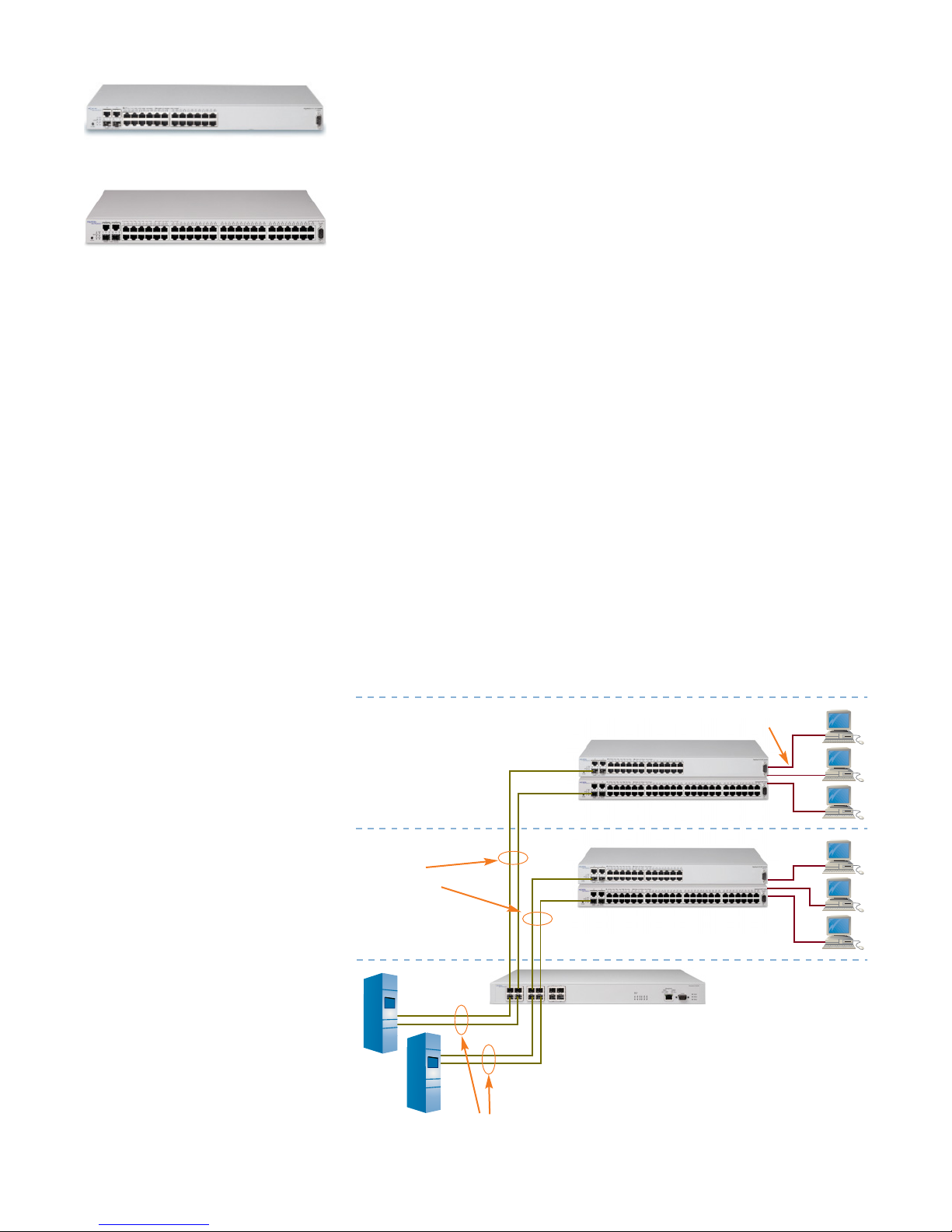
Figure 1. Ethernet Switch 425-24T
Figure 2. Ethernet Switch 425-48T
Figure 3. Small/medium enterprise solution
Distributed
Multi-Link Trunking
Multi-Link
Trunking
Floor 3
Floor 2
Network
Center
Ethernet Switch 425
Ethernet Switch 425
Ethernet Routing Switch 1612G
10/100 Mbps
connections
Servers
Page 3
3
speed. Each of the switched ports can
also automatically detect and support
full-duplex connections to servers, poweruser end stations or other switches, as
well as half-duplex connections to legacy
devices or hubs.
Custom Auto Negotiation
Advertisements (CANA)
CANA enables the network manager to
tune the autonegotiation capabilities of
any particular Ethernet port. The capabilities include half-duplex and fullduplex modes with speeds of 10, 100
and 1000 Mbps. This feature enables
the network manager to determine
which capabilities should be set as the
maximum supported on the network
and saves the network manager from
having to go to each workstation and
switch to configure a “fixed” speed. The
switch can then negotiate with the
connected device for the highest common
capabilities according to the parameters
defined by CANA for that port. This can
be particularly useful where the network
manager wished to limit the maximum
speed or duplex due to cabling limitations or business requirements.
High-density stacking
architecture
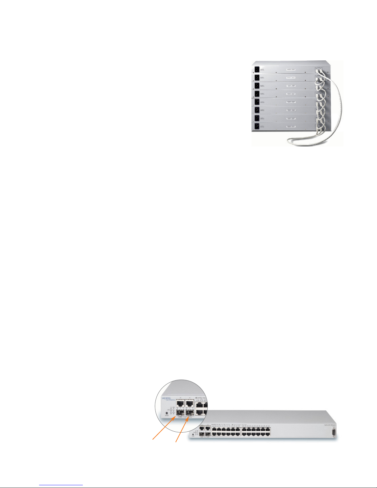
The plug-and-play stacking architecture
of the Ethernet Switch 425 permits the
inter-connection of up to eight switches
with stacking cables into a single manageable entity of up to 384 10/100-Mbps
ports. Two built-in Gigabit stacking
ports in the rear of the switch provide
easy connections to other members of
the stack; there is no need to purchase a
cascade module or use an uplink port
for stacking.
This scalable stacking architecture of the
Ethernet Switch 425 protects the network
investment as business needs change or
grow. Enabling users to increase the port
density at the wiring closet as the busi-
ness expands as well as providing high
availability through features such as
Nortel’s Distributed Multi-Link Trunking
(DMLT) are some of the key advantages
of Nortel’s stacking technology.
The Ethernet Switch 425-24T and
Ethernet Switch 425-48T can be stacked
in combination as of version 3.6 software
to deliver added flexibility for customer
configurations. To further enhance the
flexibility of stacking, the Ethernet Switch
425-24T switch can be stacked using
version 3.1 or earlier software in any
combination up to a maximum of
eight units.
High-speed uplink ports
The Ethernet Switch 425 switches offer
two built-in combo uplink ports (ports
25 and 26 on the Ethernet Switch
425-24T and ports 49 and 50 on the
Ethernet Switch 425-48T) in the front
of the unit that provide high-speed
connectivity to backbone switches or
servers. Each combo port consists of one
SFP GBIC (Small Form Factor Pluggable
Gigabit Interface Converter) port and
one 10/100/1000BASE-T port. Each
combo port autosenses between the SFP
GBIC and the 10/100/1000BASE-T
port and will enable either the SFP port
or the 10/100/1000BASE-T port
depending on the presence of a link. In
a stack of eight Ethernet Switch 425
products, up to eight uplink ports can
be used, delivering up to 16 Gbps of
uplink bandwidth.
Layer 2 features
VLAN support
The Ethernet Switch 425 family of
products supports up to a maximum of
255 port-based VLANs which can be
established for each switch, to extend
the broadcast domain and segment
network traffic for higher network efficiency. The 255 VLANs can be configured on a standalone switch or across
the stack. IEEE 802.1Q VLAN Trunking
is supported on every port of the switch,
allowing efficient means of transporting
broadcast domains across switches.
Additionally, the Ethernet Switch 425
provides the ability to have both tagged
and untagged frames on the same port
for easy traffic segmentation with
minimal setup.
Figure 4. The plug-and-play
architecture allows easy expansion
and management as a single unit
Combo
Port 26
Combo
Port 25
Figure 5. Each combo port auto-senses between 1 SFP uplink port and
1 10/100/1000BASE-T port
Page 4

4
Enterprise-sized
MAC address table
The Ethernet Switch 425 switches support
up to 8,000 MAC addresses to support
ample scalability for growing networks to
accommodate many attached devices and
workgroups connected to each switch.
IGMP snooping
The Ethernet Switch 425 products from
Nortel feature IP Multicast support by
enabling the examination (‘snooping’) of
all Internet Group Multicast Protocol
(IGMPv1 and IGMPv2) traffic. This
function is performed in hardware and
enables the filtering out (dropping) of
multicast streams not of interest to
particular end stations, thereby enabling
peak computer performance.
Spanning Tree Protocol
Built-in support for Spanning Tree
Protocol (IEEE 802.1D) detects and
eliminates logical loops in the network.
When multiple paths exist, the switch
will automatically place some ports on
standby to form a network with the most
efficient traffic pathways, avoiding the
formation of loops within the network.
Rapid Spanning Tree Protocol
Rapid Spanning Tree Protocol (RSTP
or IEEE 802.1w) is a newer version of
IEEE 802.1D Spanning Tree that provides
a more rapid recovery from network
failures. In certain configurations, the
recovery time of RSTP can be reduced
to one second. RSTP also reduces the
amount of flooding in the network by
enhancing the way Topology Change
Notification (TCN) packet is generated.
Multiple Spanning
Tree Protocol
Multiple Spanning Tree Protocol (MSTP
or IEEE 802.1s) allows you to configure
multiple instances of RSTP on the same
switch or stack. Each RSTP instance can
include one or more VLANs, thereby
enabling the configuration of multiple
spanning tree domains.
Link Aggregation
Control Protocol
Link Aggregation (LA or 802.3ad) allows
for the dynamic creation and management of trunk groups. Network administrators can configure a trunk group
automatically through the use of the
Link Aggregation Control Protocol
(LACP). LACP is a dynamic protocol
defined by the IEEE 802.3ad standard
that allows a switch to learn the presence
and capabilities of another switch by
exchanging information before a trunk
group is formed. Either switch can
accept or reject the aggregation request
on a per-port basis. A link that cannot
join a trunk group can continue to
operate as an individual link.
802.3ad provides an industry-standard
method for bundling multiple links
together to form a single trunk between
two networking devices. Trunks that
conform to the 802.3ad standard are
Link Aggregation Groups (LAGs). The
maximum number of LACP-based trunk
groups on a switch (in either standalone
or stacked configuration) is six with a
maximum of four ports active for each
trunk group.
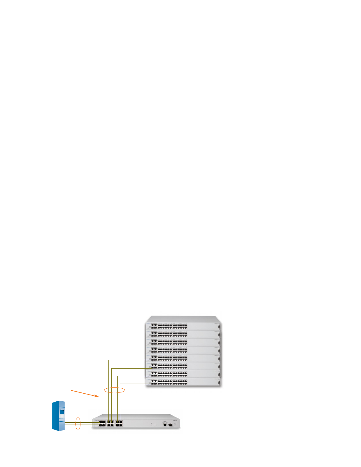
Multi-Link Trunking
Multi-Link Trunking (MLT) enables
grouping of links between an Ethernet
Switch 425 and another switch or a
server to provide greater bandwidth
with active redundant links. Nortel’s
unique Distributed Multi-Link Trunking
(DMLT) feature allows trunked ports to
span multiple units of the stack for
redundant connectivity to mission-critical servers and the network center. The
Ethernet Switch 425 supports up to six
MLT groups per switch or stack with up
to four ports per MLT.
Switch security
IEEE 802.1x
For added security, Ethernet Switch 425
models support the 802.1x-based security feature. Based on the IEEE 802.1x
standard, EAP limits access to the network
based on user credentials. A user is
required to “login” to the network using
a username/password; the user database
is maintained as a centralized authentication server, enabling common
management of users.
EAP prevents connectivity to the network
without password authorization for
added security and control. It is typically
used where access to the network is not
100 percent physically secure or where
physical security requires additional
enhancement. Some companies will
deploy EAP as standard for all network
ports to provide an added layer of
network defense, requiring that all users
are authenticated before access is granted.
EAP supports client access to the network
and interoperates with Microsoft
Windows XP and other compliant
802.1x clients.
MAC address-based security
BaySecure MAC address-based security
allows authentication of all access, not
only to the switches for management
and configurations, but also access to
the infrastructure through these switches.
This software feature limits access via
proper MAC address identification (up
to a maximum of 448).
Destination Address filtering
Destination Address filtering allows the
extension of the MAC address-based
security feature (BaySecure) to configure
the switch to drop all packets with specified MAC DAs. The Ethernet Switch
425 will support up to 10 specific MAC
DAs to be blocked due to security or
management requirements.
Page 5
5
RADIUS authentication
The RADIUS security feature allows the
Ethernet Switch 425 to require a username and password to access the switch.
This username and password have the
advantage of being centrally administered, allowing easy changes and access
control to be granted for switch access
(including Console, Telnet and Web).
In the event that the RADIUS server is
unreachable, the network manager can
use the local switch password to log into
the switch.
Secure Shell Access (SSH)
Secure Shell (SSHv2) supports strong
authentication and encrypted communications to the switch for management.
An SSH connection from a client to the
switch provides a secure network connection for menu or CLI commands. This
feature is ideal for security-conscious
customers.
SNMPv3
SNMPv3 provides user authentication
and data encryption for higher security
for switch management via SNMP. It
also offers secure configuration and
monitoring and can be used in combination with Nortel network management
applications.
HTTP port number change
This feature allows you to specify the
UDP/TCP port number to be used for
Hypertext Transfer Protocol (HTTP)
switch connections. Beginning with
software release 3.5, the HTTP port
number can be changed to enhanced
security and network access.
Traffic management and
Quality of Service
IEEE 802.1p priority queuing
802.1p priority queuing is a standardsbased Quality of Service mechanism
that enables the Ethernet Switch 425 to
forward packets in priority order on a
per-port basis. 802.1p can be utilized if
VLAN tagging (802.1Q) is enabled on
the port as the priority information is
contained in the 802.1Q VLAN tag.
The Ethernet Switch 425 supports four
queues for the classification and prioritization on network traffic. For example,
if messages from a specific segment are
crucial to the network, the switch port
connected to that segment can be set to
a higher priority level to ensure that
traffic is queued to the destinations
before other traffic.
DSCP classification
This feature enables the Ethernet Switch
425 models to classify the DiffServ Code
Point (DSCP) field within the incoming
IP packet. Based on the classification of
the DSCP value, the switch can prioritize
the packet to any one of eight possible
802.1p priorities within the switch. This
can then enable the prioritization of
specific traffic types — for example,
voice based on the DSCP setting.
Broadcast and Multicast
Rate Limiting
Broadcast and Multicast Rate Limiting
allow the switch to apply limits to the
amount of incoming broadcast and
multicast traffic across the switch. The
thresholds can be configured according
to network requirements, enabling the
administrator control over this type of
traffic which can cause disruption to
other normal data. If the configured
threshold is exceeded on a port, the
switch will drop extra packets received
to protect the network.
Switch management
Default IP address
The Ethernet Switch 425 enables rapid
setup through the setup of a Default IP
address. This enables an administrator
to connect to the switch using a standard
network cable and configuration can
then quickly occur using any of the
following features.
Username and password
authentication
The Ethernet Switch 425 provides local
switch management using username and
password authentication. The network
manager can assign Read Only or Read/
Write privileges to different users for
management access to the switch.
Figure 6. Distributed Multi-Link Trunking (DMLT) across a stack
Server
Ethernet Switch 425 switches
Ethernet Routing Switch 1612G
DMLT across the stack with
load-balancing and fail-over
protection for uninterrupted
access to servers or the
network center
Page 6

6
Web Quick Start
The Web Quick Start feature allows the
administrator to set up basic configurations on the Ethernet Switch 425 using
a single Web page. This significantly
reduces complexity and speeds system
installations.
Web management
Web-based network management makes
managing the Ethernet Switch 425 easy
using a standard Web browser. Summary,
configuration, fault, statistics, application,
administration and support pages are
provided. Real-time sampling provides
up-to-date LED and statistical information. The Web interface also allows for
configuration of numerous parameters
of the switch.
Java Device Manager
The process of configuration begins
with a single device but finishes across
multiple devices. Java Device Manager is
the device configuration tool for those
functions that require communicating
with a single device. It uses a common
user interface and workflow that supports
many Nortel Ethernet switches. This
commonality allows the network manager
to become familiar with one tool to
configure their network with a simple
graphical user interface.
Ethernet Switch
System Software
Ethernet Switch System Software provides
a single software image that is used for
Ethernet Switch 325-24T, 325-24G,
425-24T and 425-48T models. Ethernet
Switch System Software is supported
across other Nortel Ethernet Switches
for seamless integration into the network.
Simplified network operations
Ethernet Switch System Software simplifies network operations by reducing the
number of steps required for switch
software updates. A single image is all
that needs to be downloaded from the
Nortel Web site for all Ethernet Switch
325/425 models and can also be used
with Ethernet Switch 420 switches.
When in a stack, the image is loaded
only to the base unit of the stack, which
automatically loads it to other switches,
minimizing the complexity of upgrading
software images.
SNMPv1 and v2 support
Full SNMP manageability is supported
across the Ethernet Switch 425 family.
Users can configure SNMP communities as well as establish access levels.
Traps are also supported with the additional ability to change the UDP port to
which traps are sent for security.
Single stack management
Nortel was the pioneer in stacking technology. The Ethernet Switch 425 features
some of these unique benefits, enabling
single IP address management, configuration and operation of up to eight
switches in a stack.
Advanced management features
The BootP and Trivial File Transfer
Protocol (TFTP) protocol support
allows for simplified and centralized
switch IP address assignment, configuration and software upgrades over the
network.
User interface push button
The user interface push button on the
front panel of the Ethernet Switch 425
provides for ease of use in configuring
the unit. The button can be enabled or
disabled by the network administrator
and allows a number of basic functions
to be programmed without a terminal
device. These functions include setting a
temporary default IP address, resetting a
unit and resetting the stack.
Nortel Command Line
Interface (NNCLI)
NNCLI provides a common industry
look and feel to the CLI commands,
thus helping to reduce training and
operational costs. The NNCLI is used
through a Telnet session or through the
serial port on the console. NNCLI can
be used to automate general management and configuration of Ethernet
Switch 425 models.
ASCII configuration file
Ethernet Switch 425 models can download a user-editable ASCII or binary
configuration file from a TFTP server.
The ASCII configuration file can be
loaded automatically at boot time or
on-demand using the management
systems (console menus or CLI). Once
downloaded, the configuration file automatically configures the switch or stack
according to the CLI commands in the
file. This feature allows the flexibility of
creating command configuration files
that can be used on several switches or
stacks with minor modifications.
ASCII configuration generator
This feature provides the ability to view
and store the switch configuration in
ASCII configuration. The generated
file can be stored on an external server
and also used to restore the switch
configuration.
Recovery configuration
file support
The recovery configuration feature allows
for storing of switch or stack parameters
on a TFTP server. Configuration
parameters can be retrieved automatically to configure a replacement switch
or stack with the same configuration.
For new installations or when a switch
has failed, this feature saves time in
reconfiguring another switch or stack.
Page 7

7
Additionally, the Ethernet Switch 425
models allow you to make changes to
the configuration of the switch and if
those configuration changes are incorrect, the switch will re-boot after a user
pre-defined amount of time and restore
the original configuration using the new
reload command.
Banner and Control-Y
The Ethernet Switch 425 models enable
a customizable banner to be displayed
when users connect to the switch and
press Control-Y to enter the menu or
CLI interfaces. A customizable banner is
seen as part of good security practices.
The banner can also be disabled and
Control-Y skipped to enable direct
access to the CLI or menu if desired.
Autosave disable
The Ethernet Switch will by default save
any changes every 60 seconds. The switch
checks for configuration changes or if a
log message is present. If one of these
two events has occurred, the system
automatically saves its configuration and
the non-volatile log to the flash memory.
Also, the system automatically saves the
configuration file if a system reset
command is invoked.
The autosave disable feature prevents
saving the configuration changes to the
flash memory. When changing configuration, runtime configuration changes
dynamically but is not saved to the flash
memory. Network administrators must
then explicitly save the configuration
using the CLI or menu.
Software updates
TFTP client support allows software
upgrades and SNMP agent updates over
the network. Additionally, after the
image has been downloaded onto the
switch, the network manager is allowed
to predictably reset the switch in order
for the new software to take effect,
providing control over the timing of the
upgrade.
IP-based switch management
BootP support provides centralized
switch IP address assignment and in the
event that a static IP address is not
assigned, the switch will automatically
look for a BootP server, simplifying
initial IP address assignment.
Port mirroring
The port mirroring feature (sometimes
referred to as ‘conversation steering’)
allows the network administrator to
designate a single switch port as a traffic
monitor. Port mirroring replicates data
from a designated switch port to the
mirrored port. The mirrored traffic can
then be used for in-depth analysis of
switched traffic patterns to troubleshoot
problems and optimize network configurations. The Ethernet Switch 425
family supports both ingress and egress
port mirroring.
Port naming
This feature provides the ability to name
each port on the switch with a dedicated
text string. It can enable the easy identification of the connected devices and users.
LED indicators
The LED indicators on the front panel
make it easy to monitor the switch and
port status and help in isolating and
diagnosing switch problems.
Network Management
Enterprise Switch Manager
Enterprise Switch Manager (ESM) is a
Java-based, real-time configuration
management application for Nortel LAN
products including Ethernet Switch 425.
It enables network managers to discover,
view and configure more than 500
network devices and their physical links
on a topology map. Configuration is
stored in NVRAM (Non-Volatile
Random Access Memory).
Fault management
and resolution
With Enterprise Network Management
System (ENMS), the network manager
has quick access to the information
required to manage and isolate all network
events on Ethernet Switch 425 models.
Tools, such as Physical Topology View,
inform the network manager of how a
particular event is affecting the physical
connectivity within the network. The
‘End Node Locate’ tool provides the
ability to locate a failing end node and,
with one mouse click, provides access to
the RMON statistics for the failing
Ethernet port supporting that end node.
These solutions provide visual and statistical tools necessary to quickly resolve
network events or to manage performance in real-time. The Ethernet Switch
425 supports “syslog” capability that helps
in troubleshooting network issues.
802.1ab auto-topology
Nortel’s Ethernet Switch 425 family
supports the 802.1ab auto-topology
standard in addition to Nortel autotopology. 802.1ab provides a method
for the switch and other devices that
support 802.1ab within the LAN to
advertise their identification, configuration and capabilities to neighboring
devices. Each 802.1ab-supporting device
saves the information they learn internally, which allows the network management system to model the topology of
the network by interrogating each device.
Page 8

8
Simple Network Time Protocol
Simple Network Time Protocol (SNTP)
allows you to configure the switch to
synchronize Universal Coordinated Time
(UCT) to an accuracy of one second.
This feature adheres to the IEEE RFC
2030 (MIB is the s5agent). With this
feature, the system can obtain the time
from any RFC 2030-compliant NTP/
SNTP server. Additionally, the Ethernet
Switch supports the capability to modify
the time zone reported by the switch
and automatically adjust the time for
daylight savings.
RMON
Network management begins with
the device. Ethernet Switch 425
models support four groups of Remote
Monitoring (RMON) on all ports and
are SNMPv3 compliant. The four
groups of RMON are Alarms, Events,
History and Statistics. RMON2 support
is achievable via port mirroring and the
use of an external probe. The SNMP
agent software resides in the switch and
uses the information it collects to provide
management for all ports in the stack,
providing comprehensive network
monitoring capabilities.
Summary
With more than 100 years in telecommunications, Nortel is uniquely positioned
to help your business reduce cost by
combining voice and data into an integrated system. Why take a chance on a
vendor that only understands part of the
equation? Let us show you how the
Ethernet Switch 425, along with other
Nortel products, can increase your profitability, streamline your business operations, increase productivity and help
you gain the competitive edge.
Physical specifications
Ethernet Switch 425-24T:
Weight: 3 kg (6.61 lb)
Height: 4.37 cm (1.72 in)
Width: 43.82 cm (17.25 in)
Depth: 22.91 cm (9.02 in)
Ethernet Switch 425-48T:
Weight: 3.1 kg (6.83 lb)
Height: 4.37 cm (1.72 in)
Width: 43.82 cm (17.25 in)
Depth: 22.91 cm (9.02 in)
Performance
Switch fabric bandwidth—16 Gbps
Frame forwarding rate—
Ethernet Switch 425-24T 6.6 million packets per second (Mpps)
Ethernet Switch 425-48T 10.1 million packets per second (Mpps)
Switched 10 Mbps forwarding rate—14,880 pps maximum
Switched 100 Mbps forwarding rate—148,810 pps maximum
Switched 1000 Mbps forwarding rate—1,488,810 pps maximum
Memory—32MB memory architecture shared by all ports
4MB Flash Memory
16MB SDRAM
Address database size—8,000 entries at line rate
Addressing—48-bit MAC address
Frame length—64 to 1518 bytes (IEEE 802.1Q Untagged)
68 to 1522 bytes (IEEE 802.1Q Tagged)
Interface options
10BASE-T/100BASE-TX
RJ-45 (8-pin modular) connectors for Auto MDI/MDI-Xinterface
with auto-polarity
The Ethernet Swich 425 switches support the following SFP GBICs:
1000BASE-SX
Uses short wavelength 850 nm MTRJ or LC type fiber optic
connectors to connect devices over multimode (275m, 62.5um
core or 550m, 50.0um core) fiber optic cable.
1000BASE-LX
Uses long wavelength 1300nm duplex LC type fiber optic
connector to connect devices over single mode (10km, 9um core)
fiber optic cable.
Network protocol and standards compatibility
• IEEE 802.3 10BASE-T (ISO/IEC 8802-3, Clause 14)
• IEEE 802.3u 100BASE-TX (ISO/IEC 8802-3, Clause 25)
• IEEE 802.3u Autonegotiation on Twisted Pair (ISO/IEC 8802-3,
Clause 28)
• IEEE 802.3x (Flow Control on the Gigabit Uplink ports)
• IEEE 802.3z Gigabit
• IEEE 802.1d MAC Bridges (ISO/IEC 10038)
• IEEE 802.1p (Prioritizing)
• IEEE 802.1Q (VLAN Tagging)
• IEEE 802.1D (Spanning Tree Protocol)
• IEEE 802.3ad (manual/static)
• IEEE 802.3ad (LACP)
• IEEE 802.1s
• IEEE 802.1w
Technical specifications
Page 9

9
Technical specifications (continued)
RFC support
• RFC 1213 (MIB-II); RFC 1493 (Bridge MIB); RFC 2863 (Interfaces
Group MIB);
• RFC 2665 (Ethernet MIB); RFC 2737 (Entity MIBv2); RFC 2819
(RMON MIB);
• RFC 1757 (RMON); RFC 1271 (RMON); RFC 1157 (SNMP); RFC
2570 (SNMPv3);
• RFC 2571 (SNMP Frameworks); RFC 2573 (SNMPv3
Applications);
• RFC 2574 (SNMPv3 USM); RFC 2575 (SNMPv3 VACM); RFC
2576 (SNMPv3);
• RFC 2572 (SNMP Message Processing; RFC 791 (IP); RFC 792
(ICMP); RFC 793 (TCP); RFC 783 (TFTP); RFC 826 (ARP); RFC
768 (UDP); RFC 854 (TELNET); RFC951 (Bootp); RFC 2236
(IGMPv2); RFC 1112 (IGMPv1); RFC 1945 (HTTP v1.0); RFC 2138
(RADIUS); RFC 894 (IP over Ethernet); RFC 2674 (Q MIB)
Environmental
Operating temperature: 0° to 40°C (32° to 104°F)
Storage temperature: -25° to 70°C (-13° to 158°F)
Operating humidity: 10 to 85% maximum relative humidity,
noncondensing
Storage humidity: 10 to 95% maximum relative humidity,
noncondensing
Operating altitude: Up to 3,024 m (10,000 ft.) above sea level
Storage altitude: Up to 3,024 m (10,000 ft.) above sea level
Electrical
Input voltage (AC version): 100 to 240 VAC @ 47 to 63 Hz
Input power consumption (AC version): 46 W maximum
Input current (AC version): 2 A @ 120 VAC, 1 A @ 240 VAC
Maximum thermal output: 75 BTU/hour
Safety agency approvals
• UL EN60950 (UL 1950 and CSA 22.2 No. 60950)
• IEC 60950/EN60950, CB report and certificate with all
national deviations
• C22.2 No. 950 (CUL) with all national deviations
• UL-94-V1 flammability requirements for PC board
• NOM-019
Electromagnetic emissions
Meets the following standards:
• US: CFR47, Part 15, Subpart B, Class A
• Canada: ICES-003, Issue 3, Class A
• Australia/New Zealand. AS/NZS 3548:1995, Class A,
A1:1997/A2:1997 class A
• Japan: VCCI-V-3/02.04 class A
• Taiwan: CNS 13438, Class A
• Europe: EN55022:1998/A1:2000
EN61000-3-2:2000
EN61000-3-3:1995/A1:2001
CISPR 22-1997/A1:2000 Class A
Electromagnetic immunity
The Ethernet Switch 425-24T switch and Ethernet Swich
425-48T meet the EN55024:1998/A1:2001 standard.
Ordering information
Order number Description
AL2012?41** Ethernet Switch 425-24T switch with 24 10BASE-T/100BASE-TX ports plus 2 built-in combo uplink ports and built-in
stacking ports (includes rack mount kits)
AL2012?44** Ethernet Switch 425-48T switch with 48 10BASE-T/100BASE-TX ports plus 2 built-in combo uplink ports and built-in
stacking ports (includes rack mount kit)
AL2018005ˆ Ethernet Switch 420/425 Stack Cable, short (30 cm)
AL2018006ˆ Ethernet Switch 420/425 Stack Cable, long (100 cm)
AL2011012 Ethernet Switch 425 switch Rack Mount Kit
AA1419013 1-port 1000BASE-SX SFP GBIC (LC connector)
AA1419014 1-port 1000BASE-SX SFP GBIC (MT-RJ connector)
AA1419015 1-port 1000BASE-LX SFP GBIC (LC connector)
AL2011013 Console Cable for use with Ethernet Switches
** The seventh character (?) of the switch order number must be replaced with the proper code to indicate desired product nationalization:
“A” – No power cord included
“B” – Includes European “Schuko” power cord common in Austria, Belgium, Finland, France, Germany, The Netherlands, Norway, and Sweden
“C” – Includes power cord commonly used in the United Kingdom and Ireland
“D” – Includes power cord commonly used in Japan
“E” – Includes North American power cord
“F” – Includes Australian power cord, also commonly used in New Zealand and the People’s Republic of China
^ Stack cables are not included with the switches and need to be ordered separately. Stack configuration examples: For a stack of 8 switches, order 7 short
cables and 1 long cable. Follow this method for stack of 3 or more switches. For a stack of two, order two short cables only.
Page 10

Nortel is a recognized leader in delivering communications capabilities that enhance
the human experience, ignite and power global commerce, and secure and protect the
world’s most critical information. Serving both service provider and enterprise customers,
Nortel delivers innovative technology solutions encompassing end-to-end broadband,
Voice over IP, multimedia services and applications, and wireless broadband designed to
help people solve the world’s greatest challenges. Nortel does business in more than 150
countries. For more information, visit Nortel on the Web at www.nortel.com.
For more information, contact your Nortel representative, or call 1-800-4 NORTEL or
1-800-466-7835 from anywhere in North America.
Nortel, the Nortel logo and the Globemark are trademarks of Nortel Networks. Microsoft
Windows XP is a registered trademark of Microsoft Corporation. All other trademarks
are the property of their owners.
Copyright © 2006 Nortel Networks. All rights reserved. Information in this document is
subject to change without notice. Nortel assumes no responsibility for any errors that
may appear in this document.
In the United States:
Nortel
35 Davis Drive
Research Triangle Park, NC 27709 USA
In Canada:
Nortel
8200 Dixie Road, Suite 100
Brampton, Ontario L6T 5P6 Canada
In Caribbean and Latin America:
Nortel
1500 Concorde Terrace
Sunrise, FL 33323 USA
In Europe:
Nortel
Maidenhead Office Park, Westacott Way
Maidenhead Berkshire SL6 3QH UK
Phone: 00800 8008 9009 or
+44 (0) 870-907-9009
In Asia Pacific:
Nortel
Nortel Networks Centre
1 Innovation Drive
Macquarie University Research Park
Macquarie Park NSW 2109 Australia
Tel: +61 2 8870 5000
In Greater China:
Nortel
Sun Dong An Plaza
138 Wang Fu Jing Street
Beijing 100006, China
Phone: (86) 10 6510 8000
NN105060-052406
 Loading...