

Page 1

Nortel Ethernet Routing Switch 2500 Series
Fundamentals
Release: 4.2
Document Revision: 01.01
www.nortel.com
NN47215-102
.
Page 2

Nortel Ethernet Routing Switch 2500 Series
Release: 4.2
Publication: NN47215-102
Document status: Standard
Document release date: 27 October 2008
Copyright © 2008 Nortel Networks
All Rights Reserved.
Printed in Canada and the United States of America
While the information in this document is believed to be accurate and reliable, except as otherwise expressly
agreed to in writing NORTEL PROVIDES THIS DOCUMENT "AS IS" WITHOUT WARRANTY OR CONDITION OF
ANY KIND, EITHER EXPRESS OR IMPLIED. The information and/or products described in this document are
subject to change without notice.
Nortel, Nortel Networks logo, and the Globemark are trademarks of Nortel Networks.
IEEE is a trademark of the Institute of Electrical and Electronics Engineers, Inc.
Microsoft, Windows, and Windows NT are a trademarks of Microsoft Corporation.
Adobe and Acrobat Reader are trademarks of Adobe Systems Incorporated.
Sun, Solaris, and Java - are trademarks or registered trademarks of Sun Microsystems, Inc. in the United States
and other countries
SPARC is a trademark of SPARC International, Inc.
UNIX is a trademark of X/Open Company, Ltd.
All other trademarks are the property of their respective owners.
.
Page 3

.
Contents
Nortel Networks Inc. software license agreement 5
New in this release 9
Other changes 9
Introduction 11
User interface fundamentals 13
NNCLI concepts 13
Device Manager concepts 18
Web-based management concepts 39
3
User interfaces 9
Licensing 9
Configuration files 9
Supported standards and RFCs 9
NNCLI quick reference 9
Document changes 10
NNCLI command modes 14
NNCLI help 15
NNCLI access procedures 17
Interface components 18
Online help 28
Device Manager procedures 28
Device Manager download 29
Device Manager installation 29
Previous version removal 32
Device Manager startup 33
Device Manager properties configuration 33
Switch access using Device Manager 36
Telnet to a switch using Device Manager 37
SSH connection to the switch using Device Manager 37
Trap log 38
Web-based management access using Device Manager 39
Interface layout 40
Procedures for Web-based management access 43
Copyright © 2008 Nortel Networks
.
Nortel Ethernet Routing Switch 2500 Series
Fundamentals
NN47215-102 01.01 Standard
27 October 2008
Page 4

4
Licensing fundamentals 45
Stack licensing 45
License file generation 46
Generating a license 47
License file installation 48
Installing a license file using NNCLI 49
Displaying an existing license using NNCLI 49
Deleting an existing license using NNCLI 50
Installing a license file using Device Manager 50
Installing a license file using Web-based management 51
License transfer 52
Transferring a license 52
Configuration files fundamentals 55
NNCLI configuration files 55
Configuration file management procedures using NNCLI 55
Device Manager configuration files 57
ASCII and binary configuration file procedures using Device Manager 57
Web-based management configuration files 62
Configuration file procedures using Web-based management 62
Supported standards and Requests for comment 65
Standards 65
RFCs 66
NNCLI quick reference 69
Connect to the switch 70
Start NNCLI configuration from the main menu 70
NNCLI command modes 70
Command modes 70
Restart the switch using the factory default configuration 70
Configure the management IP address 71
Configure Simple Network Management Protocol (SNMP) 71
Configure VLANs and tagged uplinks 72
Configure Internet Group Management Protocol (IGMP) 72
Configure a port 72
Configure passwords 73
Configure Secure Shell (SSH) 74
Configure Telnet 74
Configure Simple Network Time Protocol (SNTP) 74
Configure log settings 74
Configure Secure Socket Layer (SSL) 74
Configure access control 75
Check a configuration 75
Copyright © 2008 Nortel Networks
.
Nortel Ethernet Routing Switch 2500 Series
Fundamentals
NN47215-102 01.01 Standard
27 October 2008
Page 5

.
Nortel Networks Inc. software license
agreement
This Software License Agreement ("License Agreement") is between
you, the end-user ("Customer") and Nortel Networks Corporation and
its subsidiaries and affiliates ("Nortel Networks"). PLEASE READ THE
FOLLOWING CAREFULLY. YOU MUST ACCEPT THESE LICENSE
TERMS IN ORDER TO DOWNLOAD AND/OR USE THE SOFTWARE.
USE OF THE SOFTWARE CONSTITUTES YOUR ACCEPTANCE OF
THIS LICENSE AGREEMENT. If you do not accept these terms and
conditions, return the Software, unused and in the original shipping
container, within 30 days of purchase to obtain a credit for the full
purchase price.
"Software" is owned or licensed by Nortel Networks, its parent or one of
its subsidiaries or affiliates, and is copyrighted and licensed, not sold.
Software consists of machine-readable instructions, its components, data,
audio-visual content (such as images, text, recordings or pictures) and
related licensed materials including all whole or partial copies. Nortel
Networks grants you a license to use the Software only in the country
where you acquired the Software. You obtain no rights other than those
granted to you under this License Agreement. You are responsible for the
selection of the Software and for the installation of, use of, and results
obtained from the Software.
5
Licensed Use of Software. Nortel Networks grants Customer a
1.
nonexclusive license to use a copy of the Software on only one
machine at any one time or to the extent of the activation or authorized
usage level, whichever is applicable. To the extent Software is
furnished for use with designated hardware or Customer furnished
equipment ("CFE"), Customer is granted a nonexclusive license to
use Software only on such hardware or CFE, as applicable. Software
contains trade secrets and Customer agrees to treat Software as
confidential information using the same care and discretion Customer
uses with its own similar information that it does not wish to disclose,
publish or disseminate. Customer will ensure that anyone who
uses the Software does so only in compliance with the terms of this
Agreement. Customer shall not a) use, copy, modify, transfer or
distribute the Software except as expressly authorized; b) reverse
Copyright © 2008 Nortel Networks
.
Nortel Ethernet Routing Switch 2500 Series
Fundamentals
NN47215-102 01.01 Standard
27 October 2008
Page 6

6 Nortel Networks Inc. software license agreement
assemble, reverse compile, reverse engineer or otherwise translate the
Software; c) create derivative works or modifications unless expressly
authorized; or d) sublicense, rent or lease the Software. Licensors
of intellectual property to Nortel Networks are beneficiaries of this
provision. Upon termination or breach of the license by Customer or in
the event designated hardware or CFE is no longer in use, Customer
will promptly return the Software to Nortel Networks or certify its
destruction. Nortel Networks may audit by remote polling or other
reasonable means to determine Customer’s Software activation or
usage levels. If suppliers of third party software included in Software
require Nortel Networks to include additional or different terms,
Customer agrees to abide by such terms provided by Nortel Networks
with respect to such third party software.
Warranty. Except as may be otherwise expressly agreed to in
2.
writing between Nortel Networks and Customer, Software is provided
"AS IS" without any warranties (conditions) of any kind. NORTEL
NETWORKS DISCLAIMS ALL WARRANTIES (CONDITIONS)
FOR THE SOFTWARE, EITHER EXPRESS OR IMPLIED,
INCLUDING, BUT NOT LIMITED TO THE IMPLIED WARRANTIES OF
MERCHANTABILITY AND FITNESS FOR A PARTICULAR PURPOSE
AND ANY WARRANTY OF NON-INFRINGEMENT. Nortel Networks is
not obligated to provide support of any kind for the Software. Some
jurisdictions do not allow exclusion of implied warranties, and, in such
event, the above exclusions may not apply.
3. Limitation of Remedies. IN NO EVENT SHALL NORTEL
NETWORKS OR ITS AGENTS OR SUPPLIERS BE LIABLE FOR ANY
OF THE FOLLOWING: a) DAMAGES BASED ON ANY THIRD PARTY
CLAIM; b) LOSS OF, OR DAMAGE TO, CUSTOMER’S RECORDS,
FILES OR DATA; OR c) DIRECT, INDIRECT, SPECIAL, INCIDENTAL,
PUNITIVE, OR CONSEQUENTIAL DAMAGES (INCLUDING LOST
PROFITS OR SAVINGS), WHETHER IN CONTRACT, TORT OR
OTHERWISE (INCLUDING NEGLIGENCE) ARISING OUT OF
YOUR USE OF THE SOFTWARE, EVEN IF NORTEL NETWORKS,
ITS AGENTS OR SUPPLIERS HAVE BEEN ADVISED OF THEIR
POSSIBILITY. The foregoing limitations of remedies also apply to any
developer and/or supplier of the Software. Such developer and/or
supplier is an intended beneficiary of this Section. Some jurisdictions
do not allow these limitations or exclusions and, in such event, they
may not apply.
4. General
— If Customer is the United States Government, the following
paragraph shall apply: All Nortel Networks Software available
under this License Agreement is commercial computer software
and commercial computer software documentation and, in the
event Software is licensed for or on behalf of the United States
Government, the respective rights to the software and software
documentation are governed by Nortel Networks standard
commercial license in accordance with U.S. Federal Regulations
Copyright © 2008 Nortel Networks
.
Nortel Ethernet Routing Switch 2500 Series
Fundamentals
NN47215-102 01.01 Standard
27 October 2008
Page 7

at 48 C.F.R. Sections 12.212 (for non-DoD entities) and 48 C.F.R.
227.7202 (for DoD entities).
— Customer may terminate the license at any time. Nortel Networks
may terminate the license if Customer fails to comply with the terms
and conditions of this license. In either event, upon termination,
Customer must either return the Software to Nortel Networks or
certify its destruction.
— Customer is responsible for payment of any taxes, including
personal property taxes, resulting from Customer’s use of the
Software. Customer agrees to comply with all applicable laws
including all applicable export and import laws and regulations.
— Neither party may bring an action, regardless of form, more than
two years after the cause of the action arose.
— The terms and conditions of this License Agreement form the
complete and exclusive agreement between Customer and Nortel
Networks.
— This License Agreement is governed by the laws of the country in
which Customer acquires the Software. If the Software is acquired
in the United States, then this License Agreement is governed by
the laws of the state of New York.
7
Copyright © 2008 Nortel Networks
.
Nortel Ethernet Routing Switch 2500 Series
Fundamentals
NN47215-102 01.01 Standard
27 October 2008
Page 8

8 Nortel Networks Inc. software license agreement
Copyright © 2008 Nortel Networks
.
Nortel Ethernet Routing Switch 2500 Series
Fundamentals
NN47215-102 01.01 Standard
27 October 2008
Page 9

.
New in this release
The following sections detail what’s new in Nortel Ethernet Routing Switch
2500 Series Fundamentals (NN47215-102) for Release 4.2.
•
"Other changes" (page 9)
Other changes
For information about changes that are not feature-related, see the
following sections:
•
"User interfaces " (page 9)
•
"Licensing" (page 9)
•
"Configuration files " (page 9)
•
"Supported standards and RFCs" (page 9)
•
"Document changes" (page 10)
User interfaces
Information about acquisition, installation, and basic operation of the user
interfaces is consolidated in this document from other documents.
9
Licensing
Stack licensing requirements and procedures are consolidated in this
document from other documents.
Configuration files
Fundamental information about working with configuration files is
consolidated in this document from other documents.
Supported standards and RFCs
The standards and RFCs supported on the switch are listed and
consolidated from other documents into a single source for easy reference.
NNCLI quick reference
Frequently used NNCLI commands are presented for reference.
Copyright © 2008 Nortel Networks
Nortel Ethernet Routing Switch 2500 Series
Fundamentals
NN47215-102 01.01 Standard
27 October 2008
.
Page 10

10 New in this release
Document changes
This document is modified to meet Nortel Customer Documentation
Standards. For more information about these standards, see Nortel
Ethernet Routing Switch 2500 Series Documentation Roadmap
(NN47215-101).
Copyright © 2008 Nortel Networks
.
Nortel Ethernet Routing Switch 2500 Series
Fundamentals
NN47215-102 01.01 Standard
27 October 2008
Page 11

.
Introduction
This document is a new publication resulting from restructuring of the
Nortel Ethernet Routing Switch 2500 Series release 4.2 documentation
suite.
Basic information about user interfaces, stack licensing, configuration file
use and management, and standards and RFCs supported on the switch,
removed from other documents, is consolidated into this new document for
easy reference. A new section, NNCLI quick reference, presents NNCLI
commands for frequently used tasks.
Navigation
•
"User interface fundamentals" (page 13)
•
"Licensing fundamentals" (page 45)
•
"Configuration files fundamentals" (page 55)
•
"Supported standards and Requests for comment " (page 65)
11
•
"NNCLI quick reference" (page 69)
Copyright © 2008 Nortel Networks
Nortel Ethernet Routing Switch 2500 Series
Fundamentals
NN47215-102 01.01 Standard
27 October 2008
.
Page 12

12 Introduction
Copyright © 2008 Nortel Networks
.
Nortel Ethernet Routing Switch 2500 Series
Fundamentals
NN47215-102 01.01 Standard
27 October 2008
Page 13

.
User interface fundamentals
This section provides basic information to help you understand the
interfaces you can use to configure and manage a Nortel Ethernet Routing
Switch. Available features depend on switch model and configuration.
Navigation
•
"NNCLI concepts" (page 13)
•
"Device Manager concepts" (page 18)
•
"Web-based management concepts" (page 39)
NNCLI concepts
Nortel Networks Command Line Interface (NNCLI) is a text-based interface
used for switch configuration and management. A common command
line interface (CLI), NNCLI follows the industry standard used for device
management across Nortel products.
13
NNCLI command modes occur in order of increasing privileges, each
based on user logon permission level. Logon password determines logon
permission level.
You can access NNCLI directly through a console connection, remotely
through a dial-up modem connection, or in-band through a Telnet session.
You can use NNCLI interactively or use the configure network command to
load and execute NNCLI scripts, manually loading the script in the console
menu or automatically loading the script at startup. For more information
about automatic configuration download, see "Downloading a configuration
file automatically using NNCLI" (page 56).
Navigation
• "NNCLI command modes" (page 14)
• "NNCLI help" (page 15)
• "NNCLI access procedures" (page 17)
Copyright © 2008 Nortel Networks
Nortel Ethernet Routing Switch 2500 Series
Fundamentals
NN47215-102 01.01 Standard
27 October 2008
.
Page 14

14 User interface fundamentals
NNCLI command modes
This section describes the use and purpose of NNCLI command modes.
NNCLI command modes separate basic user tasks from control and
management of the switch.
These command modes are available in NNCLI:
•
User Executive
• Privileged Executive
•
Global Configuration
• Interface Configuration
Command mode access is determined by access permission levels and
password protection.
If no password is set, you can open NNCLI in User Executive mode
and perform the enable command to move to the next level, Privileged
Executive mode.
However, if you have read-only access, you cannot progress beyond User
Executive mode, the default mode.
If you have read-write access you can progress from the default mode
through all of the available modes.
User Executive mode is the default NNCLI command mode and the initial
access mode. Also known as exec mode, it is the most restrictive NNCLI
mode with only basic commands available; for example, show, ping and
logout. User Executive commands are available from the other modes.
Privileged Executive mode is an unrestricted mode that can display all
switch settings. If you are logged on with write access, you can access
all configuration modes and commands that affect switch operation from
Privileged Executive mode.
In Privileged Executive mode, also known as privExec mode, you can
perform basic switch level management tasks; for example, downloading
software images, setting passwords, and starting the switch. Privileged
Executive commands are also available in Global and Interface
configuration modes.
Global Configuration mode, also known as config mode, provides
commands used to set and display general switch configurations such as
IP address, Simple Network Management Protocol (SNMP) parameters,
Telnet access, and Virtual Local Area Networks (VLAN).
Copyright © 2008 Nortel Networks
.
Nortel Ethernet Routing Switch 2500 Series
Fundamentals
NN47215-102 01.01 Standard
27 October 2008
Page 15

NNCLI concepts 15
Interface Configuration mode, also known as ifconfig mode, provides
commands used to configure parameters for each port or VLAN such as
speed, duplex mode, and rate limiting.
With sufficient permission, you can use the rules in the following table to
move between the command modes.
Command mode and sample
prompt
User Executive
2526T>
Privileged Executive
2526T#
Global Configuration
2526T<config>#
Interface Configuration
2526T<config-if>#
Entrance commands Exit commands
No entrance command, default
mode
enable exit
From Privileged Executive
mode, enter
configure
From Global Configuration
mode:
To configure a port enter
interface fastethernet
<port number>
To configure a VLAN enter
interface vlan <vlan
number>
exit
or
logout
or
logout
To return to Privileged
Executive mode, enter
end
or
exit
To exit NNCLI completely,
enter
logout
To return to Global
Configuration mode, enter
exit
To return to Privileged
Executive mode, enter
end
To exit NNCLI completely,
enter
logout
NNCLI help
This section describes help available in NNCLI.
NNCLI help is available at all levels.
Command list
To determine whether a command is available from the current mode, you
can obtain a list of all commands available from the prompt.
To obtain a list of all commands available from a prompt, enter a question
mark (?).
Copyright © 2008 Nortel Networks
.
Nortel Ethernet Routing Switch 2500 Series
Fundamentals
NN47215-102 01.01 Standard
27 October 2008
Page 16

16 User interface fundamentals
Command options
NNCLI can display command options that you can use to focus command
results.
To obtain a list of all options for a command, enter a portion of a command
followed by a space and a question mark (?) at the prompt.
Command names
If you are unsure about the correct name of a command, you can enter a
partial command name and NNCLI displays the closest match.
To obtain a correct command name, at the prompt, enter a portion of the
command name, and then press the Tab key.
The system displays the first unambiguous match for your selection. For
example, enter down + Tab and the system displays download.
Command modes
This section describes help available for NNCLI commands and modes.
To obtain help on the navigation and use of the NNCLI, perform the
help {commands | modes} command. The command is available in all
command modes.
Enter help commands to obtain information about the commands
available in NNCLI, organized by command mode. A short explanation of
each command is included.
Enter help modes to obtain information about the command modes
available and the NNCLI commands used to access them.
Keystroke shortcuts
This section provides key combinations you can use to make NNCLI
navigation easier.
The following table describes the keystroke shortcuts.
Key combination Function
Ctrl+A
Ctrl+B
Ctrl+C
Ctrl+D
Start of line
Back 1 character
Abort command
Delete the character indicated by the cursor
Ctrl+E
Ctrl+F
Ctrl+H
Copyright © 2008 Nortel Networks
.
End of line
Forward 1 character
Delete character left of cursor (Backspace key)
Nortel Ethernet Routing Switch 2500 Series
Fundamentals
NN47215-102 01.01 Standard
27 October 2008
Page 17
Key combination Function
Tab Command or parameter completion
NNCLI concepts 17
Ctrl+K and Ctrl+R
Ctrl+N or Down arrow
Ctrl+P or Up arrow
Ctrl+T
Ctrl+U
Ctrl+W
Ctrl+X
Ctrl+z
?
Esc+C and Exc+U
Esc+l
Esc+B
Esc+D
Esc+F Move 1 word forward
Redisplay line
Next history command
Previous history command
Transpose characters
Delete entire line
Delete word to left of cursor
Delete all characters to left of cursor
Exit Global Configuration mode to Privileged Executive mode
Context sensitive help
Capitalize character at cursor
Change character at cursor to lower case
Move back 1 word
Delete 1 word to the right
NNCLI access procedures
Perform the procedures in this section to access NNCLI.
Access prerequisites
• Connect to the switch with a console cable, connected directly to the
console port, or use Telnet.
•
If you connect to the switch remotely, through Telnet, ensure that you
enable remote access and that the switch IP address is valid.
•
Use a terminal or a PC, with a terminal emulator, as the NNCLI
command station.
•
If you use a console cable and console port, ensure that the terminal
emulation program conforms to the settings in the following table.
Property Value
Baud Rate 9600 bps
Data Bits
Stop Bits
Parity None
Flow Control None
Terminal Protocol VT100 and VT100/ANSI
8
1
Copyright © 2008 Nortel Networks
.
Nortel Ethernet Routing Switch 2500 Series
Fundamentals
NN47215-102 01.01 Standard
27 October 2008
Page 18

18 User interface fundamentals
Opening an NNCLI session
Procedure Steps
Step Action
1 Connect to the switch.
2
3
4
Enter the password, if applicable.
At the NNCLI Banner Screen, press CTRL+Y.
To access NNCLI, from the main menu, press c or scroll to
Command Line Interface.
5
Press Enter.
Device Manager concepts
This section provides information to obtain, install, start, and use Device
Manager.
Navigation
• "Interface components" (page 18)
•
"Online help" (page 28)
•
"Device Manager procedures" (page 28)
Device Manager is a graphical user interface (GUI) application you can
use to configure and manage the switch. The application provides a
real time graphical representation of the switch front panel and provides
network access to monitor and configure devices.
--End--
Because Device Manager is a client application that resides on a
computer, you must install the application before you can use it.
You can download Device Manager from the Nortel Web site. The Java
Runtime Environment (JRE) is bundled with the Device Manager software
and does not require a separate installation.
Device Manager uses the Simple Network Management Protocol (SNMP)
to configure and manage devices.
Interface components
This section describes Device Manager interface components and their
use in the application.
Copyright © 2008 Nortel Networks
Nortel Ethernet Routing Switch 2500 Series
Fundamentals
NN47215-102 01.01 Standard
27 October 2008
.
Page 19

Device Manager concepts 19
The Device Manager window includes the following parts:
•
Menu bar: used to access command menus
•
Toolbar: used for quick access to common commands
•
Device view: used to show a graphic representation of the device
status
•
Status bar: used to display error messages and other information
Menu bar
The following table describes the Menu bar commands. Feature availability
depends on switch model and configuration.
Command
Device Opens a device, refreshes the device view, rediscovers a device, and
Edit Opens edit dialog boxes for the objects selected in the device view.
Graph Opens statistics dialog boxes for the selected object.
VLAN Opens dialog boxes for managing VLANs, Spanning Tree Groups (STG),
IP Routing Opens configuration dialog boxes to set up IP routing functions, including
QoS Opens configuration and monitoring dialog boxes for Quality of Service
Rmon Opens configuration and monitoring dialog boxes for remote monitoring.
Actions Opens the Home page for the Web-based management session.
Help Opens online Help topics for Device Manager and provides a legend for
Description
sets the polling and SNMP properties.
From the Device menu you can also open and view the Trap Log,
SysLog, and Log and establish a Telnet or SSH connection to the
currently open device.
From the Edit menu you can also open dialog boxes for managing files
and running diagnostic tests, and enable SNTP, SNMPv3 and related
configurations.
MultiLink Trunking (MLT), and Link Aggregation Control Protocol (LACP).
ARP, IPv4 TCP/UDP, DHCP, and UDP Forwarding for the switch, .
or Differentiated Services.
the port colors in the Device view.
Toolbar
The Toolbar contains buttons that provide quick access to commonly used
commands and some additional actions.
The following table describes the Toolbar buttons and provides Menu bar
equivalents.
Copyright © 2008 Nortel Networks
.
Nortel Ethernet Routing Switch 2500 Series
Fundamentals
NN47215-102 01.01 Standard
27 October 2008
Page 20
20 User interface fundamentals
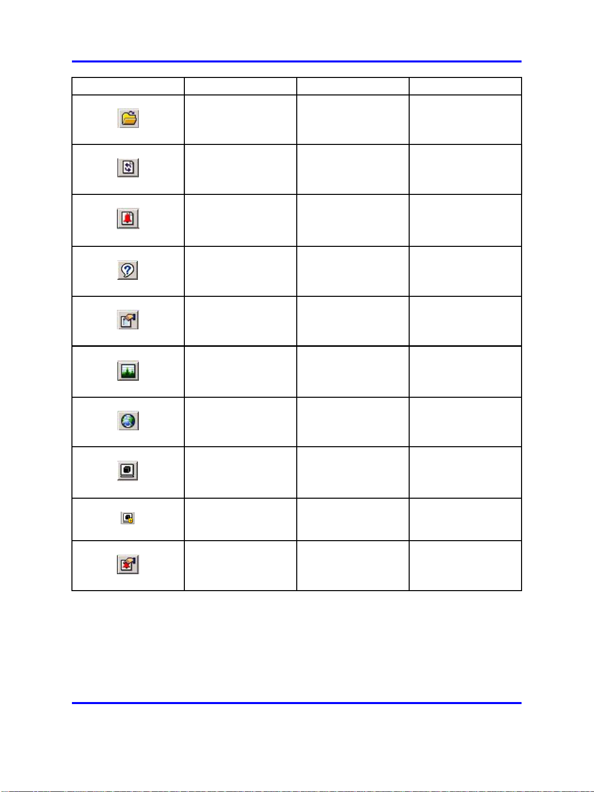
Button Name Description Menu bar equivalent
Open Device Opens the Open
Device dialog box
Refresh Device Status Refreshes the device
view information
Trap Log Opens the trap log Device > Trap Log
Help Opens online Help in a
Web browser
Edit Selected Displays configuration
data for the selected
chassis object
Graph Selected Opens statistics and
graphing dialog boxes
for the selected object
Device > Open
Device > Refresh
Status
Help > Device
Edit > Unit
Edit > Chassis
Edit > Port
Graph > Chassis
Graph > Port
Globe Opens a Web-based
management session
Telnet Opens a Telnet
session
SSH Opens an SSH
session
Alarm Manager Opens the Remote
Monitoring (RMON)
Alarm Manager
Actions > Open Home
Page
Device > Telnet
Device > SSH
Connection
Serviceability > Rmon
> Alarm Manager
Status bar
Device Manager provides a Status bar to display error and information
messages from the software applications. These messages are unrelated
to the managed device.
Copyright © 2008 Nortel Networks
.
Nortel Ethernet Routing Switch 2500 Series
Fundamentals
NN47215-102 01.01 Standard
27 October 2008
Page 21

Device Manager concepts 21
Device view
The Device view is a graphical representation of switch hardware
operating status and you can use it to perform management tasks on
specific objects. After you select a device from the Device menu, the
Device view appears.
Objects in the Device view are:
•
a stand-alone switch: called a unit in the menus and dialog boxes
• a switch stack: called a chassis in the menus and dialog boxes
•
a port
From the device view you can select single objects, groups of objects, or
the entire switch.
Device view object selection
Perform these procedures to select objects in Device view.
Selecting a single object in Device view
Procedure Steps
Step Action
1
To select a single object in Device view, a port for example, click
the edge of the object.
--End--
Selecting multiple objects in Device view
Procedure Steps
Step Action
1
To select multiple objects of the same type, for example a block
of contiguous ports, click and hold the right mouse button and
drag the pointer over the ports to select the group of ports.
2 To select multiple ports, or switches in the stack, Ctrl+click on
the objects.
--End--
Copyright © 2008 Nortel Networks
.
Nortel Ethernet Routing Switch 2500 Series
Fundamentals
NN47215-102 01.01 Standard
27 October 2008
Page 22

22 User interface fundamentals
Selecting all ports in a stand-alone switch or stack
Procedure Steps
Step Action
1 To select all the ports in a stand-alone switch or in a stack, from
the Device Manager menu bar choose Edit > Select > Ports.
Selecting all switch units in a stack
Procedure Steps
Step Action
1 To select all units in a stack, from the Device Manager menu bar
choose Edit > Select > Units.
Selecting an entire stack
Procedure Steps
--End--
--End--
Step Action
1
To select an entire stack, from the Device Manager menu bar
choose Edit > Select > Chassis.
--End--
LEDs and ports
LED color in Device view mirrors the physical switch LEDs except that
LEDs in Device view do not blink.
Ports in Device view are also color coded to demonstrate port status. To
see the port color legend, from the Device Manager menu bar choose
Help > Legend.
The following table describes the port color codes.
Color
Green Port is operating
Red Port has been manually disabled
Orange Port has no link
Light Blue Port is in standby mode - not supported in all switch models
Description
Dark Blue Port is being tested - not supported in all switch models
Nortel Ethernet Routing Switch 2500 Series
NN47215-102 01.01 Standard
Copyright © 2008 Nortel Networks
Fundamentals
27 October 2008
.
Page 23

Device Manager concepts 23
Color
Gray Port is unmanageable
Purple Port is in loopback testing mode - not supported in all switch models
Description
Shortcut menus
This section describes the port and switch shortcuts.
The switch shortcut menu provides access to basic switch hardware
information and graphing dialog boxes.
The port shortcut menu provides a faster path to edit and graph a port.
The following table describes switch unit shortcut commands.
Command
Unit # Displays the unit number.
Edit Opens a read-only dialog box that provides basic switch hardware
Show Port Tooltip Mouse over a port in the front panel view to display the port name and
Description
information.
speed.
Show port tooltip is enabled by default.
Refresh Port Tooltip Refreshes the port tooltip information if it is changed. To update the
tooltip display, from the Device Manager menu bar choose Edit > Port,
and then click Refresh Port Tooltip.
Refresh PoE status Refreshes port Power over Ethernet (PoE) status—not all switch models
have PoE.
The following table describes the port shortcut commands.
Command
Edit Opens a dialog box to set port operating parameters.
Graph Opens a dialog box to display port statistics and display statistics as a
Enable Brings a port up administratively.
Disable Shuts a port down administratively—port color changes to red in the
Description
graph.
Device view.
Shortcut menus procedures
Perform the following procedure to access the shortcut menu.
Copyright © 2008 Nortel Networks
.
Nortel Ethernet Routing Switch 2500 Series
Fundamentals
NN47215-102 01.01 Standard
27 October 2008
Page 24

24 User interface fundamentals
Accessing shortcut menus
Procedure Steps
Step Action
1 To access the shortcut menu for an object in the Device view,
right-click the object.
Objects in Device view
You can edit objects in the Device view from the Toolbar or the Shortcut
menu.
After you change a screen value, the value displays in bold.
Changes are not applied to the running configuration until you click Apply.
After changes are applied to a field, you can display the new information.
Object editing procedures
Perform the following procedures to edit objects in the Device view.
--End--
Copyright © 2008 Nortel Networks
.
Nortel Ethernet Routing Switch 2500 Series
Fundamentals
NN47215-102 01.01 Standard
27 October 2008
Page 25

Device Manager concepts 25
Selecting an object to edit from the toolbar
Procedure Steps
Step Action
1 On the toolbar, click Edit Selected.
--End--
Selecting an object to edit from the shortcut menu
Procedure Steps
Step Action
1 From the shortcut menu, choose Edit.
--End--
Displaying updated information
Procedure Steps
Step Action
1
To display new, applied information, click Refresh.
--End--
Statistics and graphs
Device Manager tracks a wide range of statistics for each switch, stack,
and port. Statistics are updated based on the poll interval.
You can view and graph statistics for single or multiple objects and export
statistics to other applications.
This section describes the types of statistics and graphs and the graph
dialog box buttons, explains how to view statistics, and how to export
statistics to other applications.
The data tables in the statistics dialog boxes list the counters, or
categories of statistics gathered, for the specified object. For example, the
categories for ports include Interface, Ethernet Errors, Bridge, and RMON.
The system can associate each statistics category with six types of
statistics.
The following table describes the types of statistics.
Copyright © 2008 Nortel Networks
.
Nortel Ethernet Routing Switch 2500 Series
Fundamentals
NN47215-102 01.01 Standard
27 October 2008
Page 26

26 User interface fundamentals
Statistic
AbsoluteValue The total count since the last time the counters were reset.
Cumulative The total count since the statistics window was opened.
Average/sec The cumulative count for each polling interval.
Minimum/sec The minimum average for the counter for each polling interval.
Maximum/sec The maximum average for the counter for each polling interval.
LastVal/sec The average for the counter during the previous polling interval.
Description
A system restart resets all counters.
The elapsed time for the cumulative counter appears at the bottom of the
graph window.
Device Manager can create the following types of graphs:
•
line
• area
• bar
• pie
Graph type selection buttons are located at the bottom of the Statistics
window.
You can use buttons at the top of the graph window change the
orientation, scale, or graph type.
The following table describes the graph dialog box buttons.
Button Name Description
Stacked Stacks data quantities instead of displaying them side-by-side
Horizontal Rotates the graph 90 degrees
Log Scale Changes the scale of the x axis from numeric to logarithmic
Line Chart Converts an area graph or bar graph to a line graph
Copyright © 2008 Nortel Networks
.
Nortel Ethernet Routing Switch 2500 Series
Fundamentals
NN47215-102 01.01 Standard
27 October 2008
Page 27

Button Name Description
Area Chart Converts a line graph or bar graph to an area graph
Bar Chart Converts a line graph or area graph to a bar graph
Statistics and other applications
Perform this procedure to export statistics to other applications.
Exporting statistics
Procedure Steps
Step Action
Device Manager concepts 27
1
To export statistics to a tab-separated file format and import that
file to other applications, click Export data at the bottom of the
Statistics window.
--End--
Graph view methods
You can view graphs from Device Manager statistics using the toolbar, the
shortcut menu, or the main menu.
Viewing statistics as graphs using the toolbar
Procedure Steps
Step Action
1 Select the objects to graph.
2 On the toolbar, click Graph Selected.
3 From the Statistics window, select a statistics group tab to view.
4 On the data table, click and hold the right mouse button and drag
the pointer over the cells you want to graph. You selections must
reside in the same row or column.
5 Click one of the graph buttons at the bottom of the graph window
to select a graph type.
6 Click Print to print a copy of the graph.
Copyright © 2008 Nortel Networks
.
--End--
Nortel Ethernet Routing Switch 2500 Series
Fundamentals
NN47215-102 01.01 Standard
27 October 2008
Page 28

28 User interface fundamentals
Viewing statistics as graphs using the shortcut menu
Procedure Steps
Step Action
1 Select the objects to graph.
2
3 From the Statistics window, select a statistics group tab to view.
4
From the shortcut menu, select Graph.
On the data table, click and hold the right mouse button and drag
the pointer over the cells to graph. Your selections must reside
in the same row or column.
5
Click one of the graph buttons at the bottom of the graph window
to select a graph type.
6
Click Print to print a copy of the graph.
--End--
Viewing statistics as graphs using the main menu
Procedure Steps
Step Action
1
2 From the Device Manager menu bar, for a stack choose Graph >
Select the objects to graph.
Chassis or, for a port, choose Graph > Port.
3 From the Statistics window, select a statistics group tab to view.
4 On the data table, click and hold the right mouse button and drag
5 Click one of the graph buttons at the bottom of the graph window
6 Click Print to print a copy of the graph.
Online help
Online help is context-sensitive and appears in the Web browser.
Click Help on the Device Manager toolbar to display Help.
Device Manager procedures
Perform the procedures in this section to get, install, and use Device
Manager.
Copyright © 2008 Nortel Networks
the pointer over the cells to graph. Your selections must reside
in the same row or column.
to select a graph type.
--End--
Nortel Ethernet Routing Switch 2500 Series
Fundamentals
NN47215-102 01.01 Standard
27 October 2008
.
Page 29

Navigation
• "Device Manager download" (page 29)
• "Device Manager installation" (page 29)
•
"Previous version removal" (page 32)
• "Device Manager startup" (page 33)
• "Device Manager properties configuration" (page 33)
• "Switch access using Device Manager" (page 36)
• "Telnet to a switch using Device Manager" (page 37)
• "SSH connection to the switch using Device Manager" (page 37)
• "Trap log" (page 38)
• "Web-based management access using Device Manager" (page 39)
Device Manager download
Perform this procedure to download Device Manager.
Downloading the application
Procedure Steps
Device Manager concepts 29
Step Action
1
2 Enter w
3
4 Select Software Downloads.
5 Select Network Management.
6 From Switches & Routers, select Java Device Manager.
7
8 Download the appropriate version for your system.
Open a Web browser.
ww.nortel.com/support
Select Support & Training.
Click the latest version.
Device Manager installation
This section provides procedures for installing Device Manager on a
computer. Procedures for two operating systems are included: Microsoft
Windows environment and UNIX environment.
--End--
Copyright © 2008 Nortel Networks
.
Nortel Ethernet Routing Switch 2500 Series
Fundamentals
NN47215-102 01.01 Standard
27 October 2008
Page 30

30 User interface fundamentals
Prerequisites for Device Manager installation
The minimum requirements for Device Manager installation in a Windows
environment are as follows:
•
Ensure that all previous versions of the software are uninstalled and
that the new application version is installed in a new directory. Nortel
recommends that you use Uninstall DM to remove existing Device
Manager software versions.
•
Close all programs.
• Use one of these operating systems—Windows NT, Windows 95,
Windows 98, Windows 2000, Windows XP, Windows 2003, or Windows
Vista.
• Ensure that your CPU is Pentium II 350 MHz or greater.
•
Ensure that your PC memory has 256 MB DRAM or better.
•
Ensure that your PC hard drive has 300 MB of available space.
The minimum requirements for Device Manager installation in a UNIX
environment are as follows:
•
Use one of these operating systems—Sun Solaris 2.8x or higher or
Linux Kernel 2.2 or higher.
•
Ensure that your computer memory has 128 MB DRAM or better.
• Ensure that your hard drive temporary directory has 4 MB.
•
Ensure that your hard drive installation directory has 300 MB.
Attention: If you use SPARC versions 5.8, 5.9, or 5.10, you must install
Sun Solaris operating system patches before installing Device Manager.
Following is a patch procedure for SPARC versions 5.8, 5.9, and 5.10.
Installing a Sun Solaris patch
Procedure Steps
Step Action
1 On the Solaris workstation, enter the uname -1 command to
determine the installed Solaris version.
2 Open a Web browser window and type sunsolve.sun.com to
access the Sun Microsystems technical support Web site.
Copyright © 2008 Nortel Networks
.
Nortel Ethernet Routing Switch 2500 Series
Fundamentals
NN47215-102 01.01 Standard
27 October 2008
Page 31

Device Manager concepts 31
3
Follow the directions on the Web page to find and install the
appropriate patch.
--End--
Installing from a Windows environment
Procedure Steps
Step Action
1 Locate the downloaded executable Device Manager file on the
local computer.
2 Double-click the executable file to start the installation process:
example jdm_xxx.exe (xxx represents the software version
number).
3
4 Read and accept the license agreement, and then click Next.
5 Nortel recommends that you select the Typical installation
After the installation programs loads, read and follow the
instructions on the Introductory window and click Next.
option on the Windows Choose Install Sets window but, if you
require a more specialized installation, select one of the other
options, and then click Next.
6 On the Windows Choose Install Folder window, type a local
file system location to install the application. You can also click
Choose to select a location, or click Restore Default Folder to
restore the default installation location. Click Next to proceed.
7
Select a location for the Start menu icon placement, and then
click Next.
8 Confirm your selections on the Pre-Installation Summary
window, and then click Install to begin installation.
9
If changes are required, click Previous to return to the
appropriate location.
10 After the installation process is complete, click Done.
--End--
Installing from a UNIX environment
Procedure Steps
Step Action
1 To install Device Manager in a UNIX environment, close all
programs. For more information about using SPARC version 5.8,
5.9, or 5.10, see "Prerequisites for Device Manager installation "
(page 30).
Copyright © 2008 Nortel Networks
.
Nortel Ethernet Routing Switch 2500 Series
Fundamentals
NN47215-102 01.01 Standard
27 October 2008
Page 32

32 User interface fundamentals
2
Locate the downloaded executable Device Manager file on the
local computer.
3 Double-click the executable file to start the installation process.
For more information about UNIX file names, see "UNIX file
naming job aid" (page 32).
4 After the installation programs loads, read and follow the
instructions on the Introductory screen, and then click Next.
5 Read and accept the license agreement. and then click Next.
6 Nortel recommends that you select the Typical installation
option on the UNIX Choose Install Sets window but, if you
require a more specialized installation, select one of the other
options, and then click Next.
7
On the UNIX Choose Install Folder window type a local file
system location to install the application. You can also click
Choose to select a location, or click Restore Default Folder to
restore the default installation location. Click Next to proceed.
8 Confirm your selections on the Pre-Installation Summary
window, and then click Install to begin installation.
9
If changes are required, click Previous to return to the
appropriate location, and then make the changes.
10
After the installation process is complete, click Done.
--End--
UNIX file naming job aid
The following table describes UNIX file name formats.
Operation system
Sun Solaris jdm_XXXX_solaris_sparc.sh
Linux jdm_XXXX_linux.sh
XXXX in the file names represents the software version number
File name
Previous version removal
If no Uninstall DM utility exists in your Windows Start menu, perform this
procedure to remove the existing Device Manager software.
Uninstalling Device Manager
Procedure Steps
Step Action
1 Go to the Device Manager software folder.
2 Open the UninstallerData subfolder.
Copyright © 2008 Nortel Networks
.
Nortel Ethernet Routing Switch 2500 Series
Fundamentals
NN47215-102 01.01 Standard
27 October 2008
Page 33

Device Manager concepts 33
3
Run the file Uninstall Java Device Manager.exe.
Device Manager startup
This section provides procedures for starting Device Manager, in Windows
and in UNIX environments.
Starting from a Windows environment
Procedure Steps
Step Action
1
2 Select Programs.
3
4 Select DM.
From the Windows task bar, select Start.
Select Java Device Manager.
Starting from a UNIX environment
Procedure Steps
--End--
--End--
Step Action
1
In a UNIX environment, verify that the Device Manager
installation directory is in your search path.
2
Enter ./JDM.
--End--
Device Manager properties configuration
This section provides procedures for setting Device Manager properties to
configure communication parameters such as the polling interval, timeout,
and retry count.
Setting properties before access
Procedure Steps
Step Action
1 To set Device Manager properties for the first time, from the
Device Manager menu bar, choose Device > Properties >
Current.
2 Configure the properties in the Properties window.
Copyright © 2008 Nortel Networks
.
Nortel Ethernet Routing Switch 2500 Series
Fundamentals
NN47215-102 01.01 Standard
27 October 2008
Page 34

34 User interface fundamentals
3
Click OK.
--End--
Setting properties after access
Procedure Steps
Step Action
1 To set Device manager properties after you access a device,
from the Device Manager menu bar choose Device > Properties
> Devices.
2 Select the IP address of a device from the Properties Device
List.
3
4 Configure the properties in the Properties window.
5 Click OK.
Click Edit.
--End--
Variable definitions
Area Item Description
Polling
Status Interval Interval at which statistics and status information is gathered.
For a full stack, set this interval to between 120 and 300
seconds.
Hotswap Detect
every
Enable Enables (true) or disables (false) periodic polling of the device
The frequency at which Device Manager polls for hot swap
module information. This value relates to the Status Interval
value. For example, if the status Interval is set to 120, and the
value for Hotswap Detect every is 2, Device Manager polls
the hot swap modules every 240 seconds. For less hot swap
polling, set the value to poll every 2 or 3 intervals.
for updated status. If polling is disabled, the chassis status is
updated only after you choose Device > Refresh Status.
Copyright © 2008 Nortel Networks
.
Nortel Ethernet Routing Switch 2500 Series
Fundamentals
NN47215-102 01.01 Standard
27 October 2008
Page 35

Area Item Description
Device Manager concepts 35
SNMP
Retry Count The number of times Device manager sends the same polling
request if a response is not returned. The normal setting is 3
or 4 retries.
Timeout Length of each retry of each polling waiting period. If you use
a slow connection to access the device, increase the timeout
interval and change the Retransmission Strategy to superlinear.
Trace Select Trace to permit trace routes.
Listen for traps If selected (enabled), Device Manager listens for traps from the
device.
Max Traps in
Log
The specified number of traps in the trap log. The default is
500.
Trap Port Specifies the UDP port that Device Manager uses to listen for
SNMP traps.
Listen for
Allows Device Manager to listen to the syslog.
Syslogs
Confirm row
deletion
Default Read
Community
Default Write
Community
If selected (enabled), Device Manager displays a confirmation
dialog box before deleting a row or entry from a table.
Specifies the Default Read Community string. To edit the string,
highlight the current value and type over it.
Specifies the Default Write Community string. To edit the string,
highlight the current value and type over it.
Application
Control
Web Manage
ment
Application
launch with ring
tone
Enabled by default, you can modify this field only during
configuration of the Device Manager default properties. You
cannot modify the ring tone during configuration of device
properties.
Save SNMPv3
Devices Open
Last
Disabled by default, if you enable this field the system displays
a security warning message because, if you set SNMPv3
devices to open last, users can access the device without
entering the SNMPv3 security criteria.
If you disable this field, all SNMPv3 device data saved
previously is erased and the system displays a warning
message.
You can modify this field only during configuration of the Device
Manager default properties, not during configuration of device
properties.
Http Port Specifies the application HTTP port. The default port is 80.
To access the Device Home Page using the Web, ensure that
the HTTP Port attribute matches the switch configuration. If
you change the port number, the system prompts you with a
warning message.
Copyright © 2008 Nortel Networks
.
Nortel Ethernet Routing Switch 2500 Series
Fundamentals
NN47215-102 01.01 Standard
27 October 2008
Page 36

36 User interface fundamentals
Area Item Description
Application
Launch from
JDM
Switch access using Device Manager
Telnet Default Telnet is the preset for the operating system. To define
a specific Telnet, select User-Defined and specify the Telnet
path and parameters.
SSH Default SSH is preset in Device Manager. To define a specific
SSH, select User-Defined and specify the SSH client path and
parameters.
Perform the procedure in this section to open a device using Device
Manager.
Prerequisites
•
Obtain the IP address or DNS name of the switch.
•
Obtain the SNMP community strings that determine user access.
Opening a device
Procedure Steps
Step Action
1
2
Start Device Manager.
From the Device Manager menu, choose Open > Device or
press CTRL+O to open the Open Device window.
3 Enter the switch information on the Open Device window.
4
Click Open.
--End--
Variable definitions
Field Description
Device Name A required field, you can enter an IP address or
DNS name for the device.
Read Community A required field, you can use the default
community string if enabled in Properties, Use
default community strings. The default value is
public, displayed as ******. The entry is case
sensitive.
Write Community A required field, you can use the default
community string if enabled in Properties, Use
default community strings. The default value is
public, displayed as ******. The entry is case
sensitive.
Copyright © 2008 Nortel Networks
.
Nortel Ethernet Routing Switch 2500 Series
Fundamentals
NN47215-102 01.01 Standard
27 October 2008
Page 37

Device Manager concepts 37
Field Description
Use default community strings in properties If selected, the Device Manager uses the default
community strings in Device > Properties.
v3 Enabled If selected, SNMPv3 options appear in the Open
Device window.
User Name Required if V3 is enabled, this is the name of
the user.
Context Name Specify the context name.
Authentication Protocol Required if V3 is enabled, identify the
authentication protocol used.
Authentication Password Required if V3 is enabled, specify the current
authentication password.
Privacy Protocol Required if V3 is enabled, identify the privacy
protocol.
Privacy Password Required if V3 is enabled, specify the current
privacy password.
Telnet to a switch using Device Manager
Perform this procedure to initiate a Telnet session from Device Manager to
the console interface for a switch or stack.
Establishing a Telnet connection
Procedure Steps
Step Action
1
2 On the toolbar, click Telnet.
From the Device Manager main menu, choose Device > Telnet.
--End--
SSH connection to the switch using Device Manager
Use this procedure to initiate Secure Shell (SSH) to the console interface
for a switch or stack.
Prerequisites
• The device must be SSH capable.
• SSH must be enabled.
Copyright © 2008 Nortel Networks
.
Nortel Ethernet Routing Switch 2500 Series
Fundamentals
NN47215-102 01.01 Standard
27 October 2008
Page 38

38 User interface fundamentals
Establishing an SSH connection
Procedure Steps
Step Action
1 From the Device Manager main menu, choose Device > SSH
Connection.
2 On the toolbar, click SSH.
Trap log
Perform these procedures to configure and view the SNMP trap log.
Prerequisites
•
Set the maximum number of trap entries. The default is 500.
• If you are using a UNIX platform, log on as root to receive traps.
•
Traps are received on port 162 by default.
--End--
•
If port 162 is used by another application, disable the other application
and restart Device Manager.
Setting the maximum number of trap entries for the trap log
Procedure Steps
Step Action
1
From the Device Manager menu bar, choose Device >
Properties > Current to set the maximum number of trap
entries.
2 In the Max Traps In Log box, enter the maximum number of
traps you want to collect in the trap log.
3 Click OK.
--End--
Setting the trap port
Procedure Steps
Step Action
1 From the Device Manager menu bar, choose Device >
Properties > Current to set the trap port.
2 In the Trap Port box, enter the trap port number.
Copyright © 2008 Nortel Networks
.
Nortel Ethernet Routing Switch 2500 Series
Fundamentals
NN47215-102 01.01 Standard
27 October 2008
Page 39

Web-based management concepts 39
3
Click OK.
--End--
Viewing the trap log
Procedure Steps
Step Action
1 On the toolbar, click Trap Log to view the Trap Log .
2 From the Device Manager main menu, choose Device > Trap
Log.
--End--
Exporting the trap log to a file
Procedure Steps
Step Action
1
From the Device Manager main menu, choose Device > Trap
Log or, from the toolbar, click Trap Log to export the Trap Log
to a file.
2 Click Export and following the instructions in the window.
Web-based management access using Device Manager
Perform this procedure to go to Web-based management from Device
Manager.
Opening Web-based management
Procedure Steps
Step Action
1 To open Web-based management from Device Manager, select
Actions from the toolbar.
2 Choose Open Home Page from the menu.
Web-based management concepts
Web-based management is a browser-based application for switch
configuration and management. Web-based management requires no
separate installation process.
--End--
--End--
Copyright © 2008 Nortel Networks
.
Nortel Ethernet Routing Switch 2500 Series
Fundamentals
NN47215-102 01.01 Standard
27 October 2008
Page 40

40 User interface fundamentals
Navigation
• "Interface layout" (page 40)
• "Procedures for Web-based management access" (page 43)
Interface layout
This section describes the common layout of the Web-based management
windows.
Each window is divided into two sections:
• the menu on the left side of the pane
•
the management page on the right side of the pane
Menu
The menu contains the main units of work and their corresponding options.
Some options are not available if a switch is stand-alone or in Standalone
Mode.
To open the menu, click a main header. The corresponding options appear
in a tree beneath. To display the associated management page, click an
option in the tree.
Attention: Nortel recommends that you use the interface navigation
tools. The Web browser navigation tools can interfere with the logical
navigation of Web-based management.
The following table describes Web-based management menu options.
Main heading
Summary Stack Information †
Options
Switch Information
Identify Unit Numbers †
Stack Numbering †
Description
View information about the
current state of the switch or
stack
Copyright © 2008 Nortel Networks
.
Nortel Ethernet Routing Switch 2500 Series
Fundamentals
NN47215-102 01.01 Standard
27 October 2008
Page 41

Web-based management concepts 41
Main heading
Options
Configuration IP
System
Remote Access
SNMVPv1
SNMPv3 ‡
SNMP Trap
MAC Address
Find MAC Address
Port Management
High Speed Flow Control
Software Download
Load License File
ASCII Config Download
ASCII Config Upload
Configuration File
Console/Comm Port
Fault RMON Alarm
RMON Event
RMON Event Log
System Log
Statistics Port
Port Error Summary
Interface
Ethernet Errors
Transparent Bridging
RMON Ethernet
RMON History
Description
Configure switch or stack
operation
Configure fault alarms, events,
and view event logs
View statistics for switch
functions
Applications Port Mirroring
Rate Limiting
EAPOL Secrity
MAC Address Security ‡
IGMP ‡
VLAN ‡
Spanning Tree ‡
MultiLink Trunk ‡
Link Aggregation ‡
QoS ‡
ADAC ‡
802.1 ab ‡
IP Routing ‡
DHCP Relay ‡
IpSource Guard ‡
TACACS
Nortel Ethernet Routing Switch 2500 Series
Fundamentals
NN47215-102 01.01 Standard
27 October 2008
Copyright © 2008 Nortel Networks
Configure and manage switch
applications
.
Page 42

42 User interface fundamentals
Main heading
Administration System Information
Support Help
† These options are available only if the switch is part of a stack.
‡These options have additional, associated options.
Options
Quick Start
Security ‡
CPU/Memory Utilization
Logout
Reset
Reset to Default
Release Notes
Manuals
Upgrade
The following table describes Web-based management menu icons.
Icon Description
Collapsed menu title
Click the icon to expand the menu and view all associated options.
Expanded menu title
All options associated with the menu title display underneath.
Click the icon to collapse the menu and hide associated options.
Description
Configure and manage
administrative items
Access to support facilities
Menu option
Click the icon to display the management page associated with the
menu option.
Menu option with hyperlink to related pages
Menu option associated with an action
Actions have no associated management page and take place
immediately.
Link to Nortel home page
Click this icon to open a new Web browser window and load the
Nortel home page.
Management page
The Management page is the work area. Choose a menu command to
display the associated Management page on the right side of the screen.
The Management pages contain one or more of the elements in the
following table.
Copyright © 2008 Nortel Networks
.
Nortel Ethernet Routing Switch 2500 Series
Fundamentals
NN47215-102 01.01 Standard
27 October 2008
Page 43

Web-based management concepts 43
Field Description
Display Display fields display preexisting values or statistical information. The
fields have a dimmed background and are read-only. If the data in the
field is highlighted in blue and underlined it is a hyperlink to a related
Management page.
Input Use input fields to enter or change information. Input fields have a
white background and can be edited.
Check Box Use check boxes to configure on or off parameters. If a box is blank
the parameter is disabled. Select the check box to change parameter
state.
Icons and buttons Icons and buttons on a Management page represent actions. Click
the icon or button to initiate the action.
The following table describes the Management page icons and buttons.
Icon/button Name Description
Submit Submits information to the switch
If this button is present, click to ensure that
changes are submitted.
Modify Opens a modification page for the data row
View Opens a read-only statistics page for the
data row
Delete Deletes the data row
Help Opens Help for the current Management
page in a new Web browser window
Context-sensitive Help Opens Help for the current data item in a
new Web browser window
Procedures for Web-based management access
Perform the procedure in this section to access Web-based management
of the switch.
Prerequisites
• Install one of the following Web browsers on the computer: Microsoft
Internet Explorer 4.0 or later, or Netscape Navigator 4.5.1 or later.
• Ensure that the switch has a valid, reachable IP address.
Copyright © 2008 Nortel Networks
.
Nortel Ethernet Routing Switch 2500 Series
Fundamentals
NN47215-102 01.01 Standard
27 October 2008
Page 44

44 User interface fundamentals
• Perform ping to verify the IP address or Telnet to the switch IP.
•
If the switch is not Layer 3 enabled, ensure that the device can
access the management VLAN of the switch—either through a direct
connection to a port in the management VLAN or through Layer 3
devices between the device and the switch.
Opening a Web-based management session
Procedure Steps
Step Action
1 Open a new Web browser window.
2
In the Web browser address field, type the switch or stack IP
address.
3
4 Enter the case-sensitive user name: RO for read-only access,
Press Enter.
RW for read-write access.
5
If the system is password protected, enter the password.
--End--
Copyright © 2008 Nortel Networks
.
Nortel Ethernet Routing Switch 2500 Series
Fundamentals
NN47215-102 01.01 Standard
27 October 2008
Page 45

.
Licensing fundamentals
This section provides conceptual information about licensing. Review this
section before you create a switch stack using stand-alone units.
Navigation
•
"Stack licensing" (page 45)
• "License file generation" (page 46)
• "License file installation" (page 48)
• "License transfer" (page 52)
Stack licensing
This section describes stack licensing requirements for Nortel Ethernet
Routing Switch 2500 series stand-alone switches.
You can stack multiple switches together to create a single, virtual switch
that you can manage as a single device. For more information about
switch stacking, see Nortel Ethernet Routing Switch 2500 Series System
Configuration (NN47215-500).
45
The types of Nortel Ethernet Routing Switch 2500 series switches are
• stack enabled
•
stand-alone
You can identify stack enabled units through NNCLI, Web-based
management, and Device Manager—the system includes the text Stack
Enabled in the switch description.
Stack enabled units do not require a software license to enable stacking
capability because the rear ports on stack enabled units are configured at
the factory to operate in Stacking Mode by default. You can set the rear
ports on stack enabled switches to Standalone Mode so that you can use
the switches as normal Ethernet ports to connect a server, host, or as
uplink ports, and to support the same configuration options that all front
panel ports support.
Copyright © 2008 Nortel Networks
Nortel Ethernet Routing Switch 2500 Series
Fundamentals
NN47215-102 01.01 Standard
27 October 2008
.
Page 46

46 Licensing fundamentals
You can stack stand-alone switches, but they use a software licensing
mechanism that allows stacking functionality on the rear ports of the
switch. To unlock stacking capability in a stand-alone switch, you must
install a stacking license on each stand-alone switch, and you must set the
rear ports to Stacking Mode before you can connect it to a stack.
Stacking licenses are based on the MAC address of the switch. You can
apply a stacking license file to one or more switches and one license file
can contain up to 1000 switch MAC addresses.
Stacking License Kits are purchased separately and are available in kits
of 1, 10, 50, and 100 licenses. For more information, or to order a Stack
Licensing Kit, contact your Nortel sales representative.
Each Stacking License Kit contains the following
•
a License Certificate—includes a License Authorization Code (LAC)
that allows a specific number of stacking licenses
•
an envelope containing Stacking License Installed stickers— apply the
stickers to stand-alone switches that have stacking functionality
A License Certificate contains instructions describing how to deposit
license entitlements into a license bank, enter switch MAC addresses, and
create a license file on the Nortel licensing portal Web site. The certificate
also contains instructions describing how to download and copy the license
file onto each switch requiring stack functionality.
You can purchase Stacking License Kits in combinations. For example: to
upgrade 21 stand-alone switches to allow stacking, order two AL2515002
Stacking License Kits and one AL2515001 Stacking License Kit. The two
kits provide a total of 21 licenses.
The following table provides the Stacking License Kit order codes and kit
license allocations.
Order code
AL2515001 allows stacking on 1 switch
AL2515002 allows stacking for up to 10 switches
AL2515003 allows stacking for up to 50 switches
AL2515004 allows stacking for up to 100 switches
Description
Note: 1 license is required for each switch
License file generation
This section describes what you must do after you purchase a license.
Copyright © 2008 Nortel Networks
.
Nortel Ethernet Routing Switch 2500 Series
Fundamentals
NN47215-102 01.01 Standard
27 October 2008
Page 47

After you purchase a license, you must use the Nortel licensing portal,
ww.nortellicensing.com, to generate the license file.
w
The licensing portal acts as a license bank; an electronic repository for all
license entitlements and licenses.
The system deposits license entitlements into your license bank after
you provide the License Authorization Code (LAC) from your License
Certificate.
The license file is based on authorized switch MAC addresses. You
can generate an individual license file with one or multiple switch MAC
addresses and you can add MAC addresses to the same license file at a
later time. One license file can support up to 1000 unique MAC addresses.
Generating a license
Perform this procedure to generate a license.
Prerequisites
• To allow stacking on a stand-alone switch you must purchase a
Stacking License Kit. The Stacking License Kit contains a License
Certificate with a License Authorization Code (LAC). For more
information, contact your Nortel sales representative.
License file generation 47
•
Ensure that a properly configured TFTP server resides in your network.
• Assign IP addresses to all switches.
• Obtain the switch base MAC address for each switch that requires a
license—use the NNCLI command show sys-info to obtain base
MAC addresses.
• Ensure that your browser does not automatically decompress the
compressed binary license file.
•
After you create the Software License file at the site identified
in the License Kit, you must specify a file name; example:
building100_ers2500.lic.
License file names must conform to the following restrictions
• maximum of 64 alphanumeric characters
• lowercase only
• no spaces or special characters permitted
• underscore (_) is permitted
• a dot (.), followed by a three character file extension is required
If you need to include multiple MAC addresses in a license file, use a
text-based file that conforms to the following rules:
Copyright © 2008 Nortel Networks
.
Nortel Ethernet Routing Switch 2500 Series
Fundamentals
NN47215-102 01.01 Standard
27 October 2008
Page 48

48 Licensing fundamentals
• ASCII format
•
one MAC address for each line
• no other characters, spaces, or special characters are permitted
•
MAC addresses must be in hexadecimal, capitalized format,
with each pair of characters separated by colons, example:
(XX:XX:XX:XX:XX:XX)
• file must contain correct MAC addresses - incorrect MAC addresses
result in the failure of licensed features on designated units
•
number of MAC addresses must not exceed the number allowed for
the LAC
Procedure Steps
Step Action
1 Open a Web browser, and then go to the Nortel licensing portal
ww.nortellicensing.com.
at w
2
3 Create a new license bank or provide details of an existing
Enter your contact information in the required boxes.
license bank.
4 Select an e-mail notification option to receive newly generated
licenses—after the system generates the license file, it is sent by
e-mail to the address you specified.
5 Enter the License Authorization Code (LAC) provided on the
License Certificate.
6
7
Click Submit, and then wait for the confirmation message.
After you receive the confirmation message, click Go to License
Bank to Download License.
8 In the License Bank window, select the LAC for the license you
want to generate.
9
10 In the Generate License window, enter the license file details.
11 Click Generate License File.
Click Generate License.
--End--
License file installation
This section describes what you must do after you generate the license
file.
After you obtain the license file, you must install the license file on the
switch to unlock the licensed features.
Nortel Ethernet Routing Switch 2500 Series
Copyright © 2008 Nortel Networks
.
NN47215-102 01.01 Standard
Fundamentals
27 October 2008
Page 49

You can install a license file in flash memory or on a TFTP server.
Provided that you name the license file in accordance with accepted file
naming conventions, you can apply your choice of file name and extension
to a license file generated on the Nortel licensing portal.
Do not specify a license file location—the system records and stores the
license file name while you copy the license file to the switch.
Installing a license file using NNCLI
Perform the procedures in this section to install, display or delete software
license files on the switch.
Prerequisites
To install a license on a switch you must:
•
store the license on a TFTP server
•
obtain the correct license file, containing the MAC address of the switch
where you are installing the license
To enable stacking on the switch you must:
License file installation 49
• install the license file on the switch
• set the switch rear ports to Stacking Mode
• restart the switch—Nortel recommends that you schedule system
restart during a normal maintenance window
Procedure Steps
Step Action
1 From the privExec command mode, perform this command:
copy tftp license <A.B.C.D> <WORD>.
2
Variable definitions
Parameter Description
<A.B.C.D>
<WORD>
Displaying an existing license using NNCLI
Perform this procedure to display the license installed on the switch.
Restart the switch.
--End--
TFTP server address
Software license file name on the TFTP server
Copyright © 2008 Nortel Networks
.
Nortel Ethernet Routing Switch 2500 Series
Fundamentals
NN47215-102 01.01 Standard
27 October 2008
Page 50

50 Licensing fundamentals
Procedure Steps
Step Action
1
To display the existing software license on your switch, perform
this command: show license { <1-10> | all}.
--End--
Variable definitions
Parameter Description
<1-10>
all
Displays the selected licenses
Displays all licenses
Deleting an existing license using NNCLI
Perform this procedure to delete the license installed on the switch.
Procedure Steps
Step Action
1
To delete existing software licenses from the switch, in the
privExec command mode, perform this command: clear
license { <1-10> | all}.
--End--
Variable definitions
Parameter Description
<1-10>
all
Displays the selected licenses
Displays all licenses
Installing a license file using Device Manager
You can use Device Manager to install a software license file on the
switch.
Procedure Steps
Step Action
1 From Device Manager main menu, choose Edit > File System.
2 Click License File.
3 In TftpServerInetAddressType, choose a TFTP Internet server
address type .
4 In TftpServerInetAddress, enter the TFTP server IP address.
Nortel Ethernet Routing Switch 2500 Series
NN47215-102 01.01 Standard
Copyright © 2008 Nortel Networks
Fundamentals
27 October 2008
.
Page 51

License file installation 51
5
6 In LicenseFileAction, select dnldLicense.
7
8 The system generates a restart warning message; click Yes to
In LicenseFilename, enter the software license file name.
Click Apply.
restart the switch and then activate the license, or click No to
cancel license installation.
--End--
Variable definitions
Field Description
TftpServerInetAddress
LicenseFilename
LicenseFileAction
TFTP server IP address.
License file name.
Select dnldLicense to download the license
file.
Installing a license file using Web-based management
You can use Web-based management to install a software license on the
switch.
Procedure Steps
Step Action
1
From the main menu, choose Configuration > License
Download.
2
3
4
In License Image Filename, enter the license file name.
In Select Target, select the target from the list.
In TFTP Server IP Address, enter the TFTP server IP address
in the following format: XXX.XXX.XXX.XXX.
5
6 Click Submit.
In Start Load of New License File, select Yes from the list.
--End--
Variable definitions
Field Description
License Image Filename
Select Target
Specifies the valid license file name.
From the list:
• Select the location of the license file.
Copyright © 2008 Nortel Networks
.
Nortel Ethernet Routing Switch 2500 Series
Fundamentals
NN47215-102 01.01 Standard
27 October 2008
Page 52

52 Licensing fundamentals
Field Description
TFTP Server IP Address
Start Load of New License File
Remove License File Number
License transfer
This section describes some situations that can require license transfer.
Under the following conditions, you need to transfer a license on the Nortel
Licensing portal:
• replacement of a failed switch with a new switch MAC address
• incorrect MAC address entered on the Nortel licensing portal during
license file generation
Specifies the IP address of the TFTP download
host.
From the list:
•
Select Yes to start downloading the new
license immediately.
•
Select No to cancel.
From the list:
• Select a number from 1–10 to remove a
specific license.
• Select All to remove all license files.
• Select No to cancel the operation.
•
the system displays an error message indicating that you exceed
the number of MAC address swaps for a license—for each License
authorization Code (LAC) you can swap up to 10% of the MAC
addresses; contact Nortel Technical Support to obtain a new LAC
Transferring a license
Perform this procedure to transfer a license.
Procedure Steps
Step Action
1 In the Web browser, go to the Nortel licensing portal at
ww.nortellicensing.com.
w
2 Click License Bank.
3 Enter your user name and password.
4 In the License Bank, choose the License Authorization Code
(LAC) entry associated with the license type.
5 Click View Details.
Copyright © 2008 Nortel Networks
.
Nortel Ethernet Routing Switch 2500 Series
Fundamentals
NN47215-102 01.01 Standard
27 October 2008
Page 53

License transfer 53
6
Select a transaction that contains the license file name for the
switch you are replacing.
7 Click Replace Switch.
8 In Step 1: Enter Replacement MAC Address, enter the new
MAC address.
9
In Step 2: Select the MAC Address to Replace, select the
entry for the MAC address that you want to replace .
10
Click Replace Switch MAC. If MAC replacement fails, a
message appears—
MAC swap is unsuccessful. Select a
different LAC entry and try again. If there are no other LAC
entries, contact Nortel Technical Support.
11 After the system displays the MAC swap successful message,
click Return to License Bank Details.
12
Select the transaction that contains the license file name
associated with the new MAC address.
13
Click Download.
--End--
Copyright © 2008 Nortel Networks
.
Nortel Ethernet Routing Switch 2500 Series
Fundamentals
NN47215-102 01.01 Standard
27 October 2008
Page 54

54 Licensing fundamentals
Copyright © 2008 Nortel Networks
.
Nortel Ethernet Routing Switch 2500 Series
Fundamentals
NN47215-102 01.01 Standard
27 October 2008
Page 55

.
Configuration files fundamentals
This section provides fundamental information about working with
configuration files.
Configuration files are ASCII text files that you can use to change switch
configuration quickly.
Procedures to manage binary configuration files are also included in the
Device Manager section.
Navigation
•
"NNCLI configuration files" (page 55)
•
"Device Manager configuration files" (page 57)
•
"Web-based management configuration files" (page 62)
NNCLI configuration files
This section describes how you can use NNCLI to use and manage
configuration files.
55
Configuration file management procedures using NNCLI
Perform the procedures in this section to display, store, restore, and save
configuration files using NNCLI.
Viewing current configuration
Procedure Steps
Step Action
1 At the command prompt, enter enable to enter the Privileged
2 At the Privileged Executive prompt, enter show running-conf
Copyright © 2008 Nortel Networks
Executive NNCLI mode.
ig.
--End--
Nortel Ethernet Routing Switch 2500 Series
Fundamentals
NN47215-102 01.01 Standard
27 October 2008
.
Page 56

56 Configuration files fundamentals
Saving current configuration
Procedure Steps
Step Action
1 At the command prompt, enter enable to enter the Privileged
Executive NNCLI mode.
2 At the Privileged Executive prompt, enter copy running-confi
g tftp address <A.B.C.D> filename <name>.
Saving current configuration to flash memory
Procedure Steps
Step Action
1 At the command prompt, enter enable to enter the Privileged
Executive NNCLI mode.
2 At the Privileged Executive prompt, enter copy config nvram.
--End--
--End--
Restoring system configuration from TFTP
Procedure Steps
Step Action
1
At the command prompt, enter enable to access the Privileged
Executive NNCLI mode.
2
At the Privileged Executive prompt, enter copy tftp config
address <A.B.C.D> filename <name>.
--End--
Downloading a configuration file automatically using NNCLI
Procedure Steps
Step Action
1 At the command prompt, enter enable to access the Privileged
Executive NNCLI mode.
2 At the Privileged Executive prompt, enter configure network
load-on-boot {disable | use-bootp |use-config}
Copyright © 2008 Nortel Networks
.
Nortel Ethernet Routing Switch 2500 Series
Fundamentals
NN47215-102 01.01 Standard
27 October 2008
Page 57

Device Manager configuration files 57
address <A.B.C.D> filename <name> to configure a switch
or stack to automatically load a configuration file.
--End--
Variable definitions
Parameter Description
address <A.B.C.D> Specifies the TFTP server IP address.
filename <name> Specifies the configuration file name.
load-on-boot {disable | use-bootp | use config}
Device Manager configuration files
You can use Device Manager to store the current ASCII switch
configuration file to a TFTP server, retrieve an ASCII configuration file from
a TFTP server to apply to a switch, store or retrieve a binary configuration
file, or manually save the current configuration to flash memory. You can
also designate a configuration to download automatically at switch startup
time.
Specifies the settings to automatically load a
configuration file during system startup.
disable—disables the automatic loading of the
configuration file.
use-bootp—specifies loading the ASCII
configuration file at system start and using
Bootp to obtain values for the TFTP address
and file name.
use-config—specifies loading the ASCII
configuration file at system start and using the
locally configured values for the TFTP address
and file name.
If you omit the variables, the system
immediately downloads and runs the ASCII
configuration file.
ASCII and binary configuration file procedures using Device Manager
Perform the procedures in this section to store, retrieve, and manage
ASCII and binary configuration files using Device Manager. Job aids
describing the fields on the applicable Device Manager tabs follow the
procedures.
Storing current ASCII configuration on a TFTP server
Procedure Steps
Step Action
1 From the Device Manager main menu, choose Edit > File
Copyright © 2008 Nortel Networks
.
System.
Nortel Ethernet Routing Switch 2500 Series
Fundamentals
NN47215-102 01.01 Standard
27 October 2008
Page 58

58 Configuration files fundamentals
2
Click Ascii Config File. For more information about the fields on
the Ascii Config File tab, see "ASCII configuration file job aid"
(page 60).
3 In TftpServerInetAddressType, choose the TFTP server
internet address type .
4 In TftpServerInetAddress, enter the TFTP server IP address.
5
6 In AsciiConfigManualUpload, choose uploadNow.
7 Click Apply.
In AsciiConfigFilename, enter the configuration file name.
--End--
Downloading an ASCII Configuration from a TFTP server
Procedure Steps
Step Action
1
2 Click Ascii Config File tab. For more information about the
From the Device Manager main menu, choose Edit >File
System.
fields on the Ascii Config File tab, see "ASCII configuration file
job aid" (page 60).
3
In TftpServerInetAddressType, choose the TFTP server
internet address type.
4
5 In AsciiConfigFilename, enter the configuration file name.
6 In AsciiConfigManualDownload, choose downloadNow.
7
In TftpServerInetAddress, enter the TFTP server IP address.
Click Apply.
--End--
Downloading a configuration file automatically using Device
Manager
Procedure Steps
Step Action
1 From the Device Manager main menu, choose Edit > File
System.
2 Click Ascii Config File. For more information about the fields on
the Ascii Config File tab, see "ASCII configuration file job aid"
(page 60).
Copyright © 2008 Nortel Networks
.
Nortel Ethernet Routing Switch 2500 Series
Fundamentals
NN47215-102 01.01 Standard
27 October 2008
Page 59

Device Manager configuration files 59
3
In TftpServerInetAddressType, select the TFTP server internet
address type.
4
5 In AsciiConfigAutoDownload, choose the automatic download
In AsciiConfigFilename, enter the configuration file name.
source—either useBootp, to specify loading the ASCII
configuration file at system start and using Bootp to obtain
values for the TFTP address and file name, or useConfig,to
specify loading the ASCII configuration file at system start and
using the locally configured values for the TFTP address and file
name.
6 Click Apply.
--End--
Storing a binary configuration file on a TFTP server
Procedure Steps
Step Action
1 From the Device Manager main menu, choose Edit > File
System.
2 Select Config/Image/Diag file. For more information about the
fields on the Config/Image/Diag file tab, see "Binary configuration
file job aid" (page 61).
3 In TftpServerInetAddressType, select the address type.
4
5 In BinaryConfigFilename, enter the configuration file name.
6
7 Click Apply.
In TftpServerInetAddress, enter the TFTP server IP address.
In Action, select upldConfig.
--End--
Downloading a binary configuration file from a TFTP server
Procedure Steps
Step Action
1 From the Device Manager main menu, choose Edit > File
System.
2 Select Config/Image/Diag file. For more information about the
fields on the Config/Image/Diag file tab, see "Binary configuration
file job aid" (page 61).
3 In TftpServerInetAddress, enter the TFTP server IP address.
Copyright © 2008 Nortel Networks
.
Nortel Ethernet Routing Switch 2500 Series
Fundamentals
NN47215-102 01.01 Standard
27 October 2008
Page 60

60 Configuration files fundamentals
4
5
6 Click Apply.
In BinaryConfigFilename, enter the configuration file name.
In Action, click dnldConfig.
--End--
Saving current configuration to flash memory manually
Procedure Steps
Step Action
1 From Device Manager main menu, choose Edit > File System.
2
3 Deselect AutosaveToNvramEnabled—this option is enabled
4 In Action, choose copyConfigToNvram.
5
Choose Save Configuration.
by default.
Click Apply.
--End--
ASCII configuration file job aid
The following table describes the fields on the Ascii Config File tab.
Field name Description
TftpServerInetAddressType Specifies the IP version of the TFTP server
address.
TftpServerInetAddress Specifies the TFTP server IP address.
AsciiConfigFilename Specifies the name of the ASCII configuration
file.
AsciiConfigAutoDownload
• disabled—Disables automatic loading of
ASCII configuration file at startup.
• useBootp—Specifies loading the ASCII
configuration file at startup and using BootP
to obtain values for the TFTP address and
file name.
• useConfig—Specifies loading the ASCII
configuration file at startup and using the
locally configured values for the TFTP
address and file name.
AsciiConfigAutoDldStatus Displays the configuration automatic download
status.
Copyright © 2008 Nortel Networks
.
Nortel Ethernet Routing Switch 2500 Series
Fundamentals
NN47215-102 01.01 Standard
27 October 2008
Page 61

Device Manager configuration files 61
Field name Description
AsciiConfigManualDownload downloadNow—Initiates manual configuration
download.
AsciiConfigManualDldStatus Displays the configuration manual download
status.
AsciiConfigManualUpload uploadNow—Initiates manual configuration
upload.
AsciiConfigManualUpldStatus Displays the configuration manual upload
status.
Binary configuration file job aid
The following table describes the fields on the Config/Image/Diag tab.
Field name Description
TftpServerInetAddressType Specifies the IP version of the TFTP server
address.
TftpServerInetAddress Specifies the TFTP server IP address.
BinaryConfigFilename Specifies the name of the binary configuration
file.
ImageFileName Specifies the software image file name.
FWFileName(Diagnostics) Specifies the diagnostics file name.
Action
• dnldConfig—Download a configuration file to
the switch.
•
upldConfig—Upload a configuration file to
the switch from a designated location.
• dnldImg—Download a new software image
to the switch.
• dnldImgIfNewer—Download a new software
image to the switch only it if is newer than
the current image.
• dnldImgNoReset—Download a new software
image to the switch without a switch reset.
•
dnldFW—Download a new diagnostic
software image to the switch.
• dnldFwNoReset—Download a new
diagnostic software image to the switch
without a switch reset.
Status Displays the status of the most recent action
since the last switch restart.
Copyright © 2008 Nortel Networks
.
Nortel Ethernet Routing Switch 2500 Series
Fundamentals
NN47215-102 01.01 Standard
27 October 2008
Page 62

62 Configuration files fundamentals
Web-based management configuration files
This section describes how you can use Web-based management to use
and manage configuration files.
Configuration file procedures using Web-based management
Perform these procedures to store and retrieve configuration files using
Web-based management.
Storing a configuration file on a TFTP server
Procedure Steps
Step Action
1
From the Web-based management main page, choose
Configuration > Configuration File .
2
In Configuration Image Filename, enter the name of the
configuration file.
3 In TFTP Server IP Address, enter the TFTP server IP address.
4
5 In Retrieve Configuration Image From Target, select No.
6
In Copy Configuration Image To Target, select Yes.
Click Submit.
--End--
Retrieving a configuration file from a TFTP server
Procedure Steps
Step Action
1
2 In Configuration Image Filename, enter the configuration file
From the Web-based management main page, choose
Configuration > Configuration File.
name.
3
4 In Copy Configuration Image To Target, select No.
5
6 Click Submit.
Copyright © 2008 Nortel Networks
.
In TFTP Server IP Address, enter the TFTP server IP address.
In Retrieve Configuration Image from Target, select Yes.
--End--
Nortel Ethernet Routing Switch 2500 Series
Fundamentals
NN47215-102 01.01 Standard
27 October 2008
Page 63

Web-based management configuration files 63
Retrieving a configuration file through HTTP
Procedure Steps
Step Action
1 From the Web-based management main page, choose
Configuration > Ascii Config Download.
2
In Ascii Configuration File, type the configuration file name,
including the full local path, or you can click Browse to locate the
configuration file.
3 Click Submit.
4
To check the outcome of the operation, see Last Manual
Configuration Status.
--End--
Copyright © 2008 Nortel Networks
.
Nortel Ethernet Routing Switch 2500 Series
Fundamentals
NN47215-102 01.01 Standard
27 October 2008
Page 64

64 Configuration files fundamentals
Copyright © 2008 Nortel Networks
.
Nortel Ethernet Routing Switch 2500 Series
Fundamentals
NN47215-102 01.01 Standard
27 October 2008
Page 65

.
Supported standards and Requests for
comment
For quick reference, this section lists the standards and Requests for
comment (RFC) supported by the switch.
Navigation
•
"Standards" (page 65)
•
"RFCs" (page 66)
Standards
The standards in the following list are supported on the switch:
•
IEEE 802.1X (EAPOL)
•
IEEE 802.3 (Ethernet)
• IEEE 802.3u (Fast Ethernet)
• IEEE 802.3x (Flow Control)
65
•
IEEE 802.3z (Gigabit Ethernet)
• IEEE 802.3ab (Gibabit Ethernet over Copper)
• IEEE 802.3ad (Link Aggregation)
•
IEEE 802.1AB (Link Layer Discovery Protocol)
• IEEE 802.1s (Multiple Spanning Tree Protocol—MSTP)
• IEEE 802.3af (Power over Ethernet)
• IEEE 802.1p (Prioritizing)
• IEEE 802.1w (Rapid Spanning Tree Protocol—RSTP)
• IEEE 802.1D (Spanning Tree Protocol)
• IEEE 802.1Q (VLAN Tagging)
Copyright © 2008 Nortel Networks
Nortel Ethernet Routing Switch 2500 Series
Fundamentals
NN47215-102 01.01 Standard
27 October 2008
.
Page 66

66 Supported standards and Requests for comment
RFCs
For more information about networking concepts, protocols, and
topologies, consult the following RFCs:
•
RFC 826 (ARP)
• RFC 951 (BootP)
•
RFC 2131 (BootP/DHCP Relay Agent)
• RFC 1493 (Bridge MIB)
• RFC 2737 (Entity MIBv2)
• RFC 2665 (Ethernet MIB)
• RFC 1945 (HTTP v1.0)
• RFC 792 (ICMP)
•
RFC 1112 (IGMPv1)
• RFC 2236 (IGMPv2)
• RFC 2863 (Interfaces Group MIB)
• RFC 791 (IP)
• RFC 894 (IP over Ethernet)
• RFC 1213 (MIB-II)
• RFC 2674 (Q-BRIDGE-MIB)
•
RFC 2138 (RADIUS)
•
RFC 2865 (RADIUS)
• RFC 3576 (RADIUS)
• RFC 4673 (RADIUS Dynamic Authorization Server MIB)
• RFC 1757 (RMON)
•
RFC 1271 (RMON)
• RFC 2819 (RMON MIB)
• RFC 1157 (SNMP)
• RFC 3410 (SNMPv3)
• RFC 3413 (SNMPv3 Applications)
• RFC 3411 (SNMP Frameworks)
• RFC 3412 (SNMP Message Processing)
• RFC 3414 (SNMPv3 USM)
• RFC 3415 (SNMPv3 VACM)
• RFC 793 (TCP)
• RFC 854 (Telnet)
Copyright © 2008 Nortel Networks
.
Nortel Ethernet Routing Switch 2500 Series
Fundamentals
NN47215-102 01.01 Standard
27 October 2008
Page 67

• RFC 1350 (TFTP)
• RFC 768 (UDP)
RFCs 67
Copyright © 2008 Nortel Networks
.
Nortel Ethernet Routing Switch 2500 Series
Fundamentals
NN47215-102 01.01 Standard
27 October 2008
Page 68

68 Supported standards and Requests for comment
Copyright © 2008 Nortel Networks
.
Nortel Ethernet Routing Switch 2500 Series
Fundamentals
NN47215-102 01.01 Standard
27 October 2008
Page 69

.
NNCLI quick reference
Use this chapter as a quick reference for frequently used NNCLI tasks.
For more information about using NNCLI, see "User interface
fundamentals" (page 13).
For more information about detailed configuration, see the function-specific
configuration documents for this product.
For more information about a list of documents, see Nortel Ethernet
Routing Switch 2500 Series Documentation Roadmap (NN47215-101).
Navigation
•
"Connect to the switch" (page 70)
• "Start NNCLI configuration from the main menu" (page 70)
• "NNCLI command modes" (page 70)
• "Restart the switch using the factory default configuration" (page 70)
69
• "Configure the management IP address" (page 71)
•
"Configure Simple Network Management Protocol (SNMP)" (page 71)
•
"Configure VLANs and tagged uplinks" (page 72)
•
"Configure Internet Group Management Protocol (IGMP)" (page 72)
• "Configure a port" (page 72)
• "Configure passwords" (page 73)
• "Configure Secure Shell (SSH)" (page 74)
• "Configure Telnet" (page 74)
• "Configure Simple Network Time Protocol (SNTP)" (page 74)
• "Configure log settings" (page 74)
• "Configure Secure Socket Layer (SSL)" (page 74)
• "Configure access control" (page 75)
• "Check a configuration" (page 75)
Copyright © 2008 Nortel Networks
Nortel Ethernet Routing Switch 2500 Series
Fundamentals
NN47215-102 01.01 Standard
27 October 2008
.
Page 70

70 NNCLI quick reference
Connect to the switch
You can use the following options to connect to the switch:
• remote
•
console
The following table lists the access method for three types of switch
connection.
Secure Shell (SSH) enabled SSH not enabled Console access available
Remote access Telnet access Normal console connection
access
Start NNCLI configuration from the main menu
To start a configuration using NNCLI, choose Command Line Interface
from the main menu.
At the prompt, perform these commands.
Command
enable
config t
Purpose
Enter configuration mode
Start configuration
NNCLI command modes
To perform certain functions, you must use the correct NNCLI command
mode.
The following list is a summary of NNCLI command modes:
Command modes
• User Executive (exec mode)
• Privileged Executive (privExec mode)
• Global Configuration (config mode)
• Interface Configuration (config-if mode)
For more information, see "NNCLI concepts" (page 13).
Restart the switch using the factory default configuration
Perform these commands to restart the switch using the factory default
configuration.
Command
exit
Copyright © 2008 Nortel Networks
.
Purpose
Exit the configuration mode.
Nortel Ethernet Routing Switch 2500 Series
Fundamentals
NN47215-102 01.01 Standard
27 October 2008
Page 71

Configure Simple Network Management Protocol (SNMP) 71
Command
boot default
restore factory-default [-y]
Purpose
Return a switch, or switches, to factory default
configuration.
Return a switch, or switches, to factory default
configuration where [-y] instructs the switch not
to prompt for confirmation.
Configure the management IP address
Perform these commands to configure and verify the Management IP
Address.
Command
ip address <IP> netmask <mask>
ip default-gateway <default gateway
IP>
ping <default gateway IP>
show ip
Purpose
Set the management IP and mask.
Set the default gateway IP address.
Verify connectivity.
Verify configuration.
Configure Simple Network Management Protocol (SNMP)
Perform these commands to configure SNMP.
Command
snmp-server enable
snmp-server authentication-trap
enable
snmp-server community ro
snmp-server community rw
snmp-server contact "whatever you
want"
snmp-server location "<Building &
Closet #>
snmp-server name "<switch IP
address>"
snmp-server host <host IP> <communit
y>
show sys-info
show snmp host
Purpose
Enable SNMP (default is disabled).
Enable authentication traps.
Set the read-only community name
(requirement: enter community string twice).
Set the read-write community name
(requirement: enter community string twice).
Set contact information.
Set building name and closet information.
Maintain coherent Syslog messages.
Set IP address of Jscan trap receiver.
Verify configuration.
Verify configuration.
Copyright © 2008 Nortel Networks
.
Nortel Ethernet Routing Switch 2500 Series
Fundamentals
NN47215-102 01.01 Standard
27 October 2008
Page 72

72 NNCLI quick reference
Configure VLANs and tagged uplinks
Perform these commands to configure VLANs and tagged uplinks.
Command
Vlan configcontrol automatic
vlan ports <uplink port> tagging
tagall
vlan ports <uplink port> filter-unta
gged-frame enable
vlan ports ALL filter-unregistered-fr
ame disable
vlan create <VID> type port
vlan name <VID> <name>
vlan menbers add <VID> <port listing>
vlan mgmt <VID>
vlan members remove 1 ALL
vlan ports <uplink port> pvid <VID>
show vlan
show vlan interface info
Purpose
Automatically delete old VLANs and update
PVID if a VLAN is added to an untagged port
(setting appears at the bottom of the VLAN
configuration information).
Enable tagging on the uplink.
Discard untagged frames.
Break STP for VoIP.
Create the port based VLAN and assign the
802.1q identifier.
Name the VLAN according to conventions.
Add ports to appropriate VLANs.
Set the management VLAN.
Remove all ports from VLAN 1.
Set the PVID on the uplink.
Verify VLAN configuration.
Verify configuration of PVID and port type.
Configure Internet Group Management Protocol (IGMP)
Perform these commands to configure IGMP.
Command
vlan igmp <VID> snooping enable
vlan igmp <VID> proxy enable
show vlan igmp <VID>
Purpose
Enable IGMP snooping on each appropriate
VLAN.
Enable IGMP proxy on each appropriate VLAN.
Show IGMP information for each appropriate
VLAN.
Configure a port
Perform these commands to configure a port.
Command
interface fastEthernet <end-user port
list>
Nortel Ethernet Routing Switch 2500 Series
Fundamentals
NN47215-102 01.01 Standard
27 October 2008
Copyright © 2008 Nortel Networks
Purpose
Enter configuration mode at the interface
level where you can configure multiple ports,
excluding uplink ports, simultaneously.
.
Page 73

Configure passwords 73
Command
auto-negotiation-advertisements
10-full 10-half 100-full 100-half
pause-frame
default auto-negotiation-advertiseme
nt
poe poe-shutdown
no poe-shutdown
shutdown [port]
spanning-tree learning fast
name <port name>
Exit
interface fastEthernet <uplink port>
speed auto
spanning-tree learning <normal or
disable>
name UP-<Switch IP Address>-<Slot>/<P
ort>
Exit
show interfaces all
Purpose
Set 10/100 ports to advertise only 10Mb/s half
duplex and 100Mb/s half duplex .
To advertise gigabit for gigabit ports because
Custom Autonegotiation Advertisements
(CANA) is not appropriate for gigabit ports.
Because Power Over Ethernet (PoE) is on by
default, use this command to disable PoE on
non-PoE ports.
Enable PoE for AP ports.
Disable unused ports.
Set fast spanning tree leaning on access ports.
Name uplink ports
If you need dual uplinks, Nortel recommends
that you add a second switch, in a stack, and
use port 48 of the second switch as the second
uplink.
Terminate port configuration.
Enter configuration mode at the interface level
to configure port 48 as an uplink port .
Enable autonegotiate.
Depending on the upstream switch location, set
spanning tree to normal or disabled.
Example: UP-128.206.95.254-1/2.
Terminate uplink configuration.
Display interface settings.
Configure passwords
Perform these commands to configure NNCLI passwords.
Command
cli password serial local
cli password telnet local
no password security
cli password read-only
cli password read-write
Copyright © 2008 Nortel Networks
.
Purpose
Set the switch or stack to use local passwords
for serial port access.
Set the switch or stack to use local passwords
for Telnet access.
Remove password complexity and change
frequency restrictions.
Set the read-only password (you are required to
enter the password twice).
Set the read-write password.
Nortel Ethernet Routing Switch 2500 Series
Fundamentals
NN47215-102 01.01 Standard
27 October 2008
Page 74

74 NNCLI quick reference
Configure Secure Shell (SSH)
Perform these commands to configure SSH.
Command
ssh pass-auth
ssh
show ssh global
Purpose
Enable password authentication for SSH.
To use SSHv2 for switch access, ensure that
you use SecureCRT 4.1 or higher, Putty, or
Linux SSH.
Enable SSH support.
Display SSH settings.
Configure Telnet
You can disable Telnet access to, for example, secure the switch from
remote access.
To disable Telnet access, enter telnet-access disable.
Configure Simple Network Time Protocol (SNTP)
Perform these commands to configure SNTP.
Command
sntp server primary address <IP
address>
sntp enable
show sntp
Purpose
Set SNTP server address where <IP address>
is the address of the SNTP server in decimal
notation.
Enable SNTP.
Display SNTP settings SNTP.
The SNTP default setting is Greenwich Mean
Time (GMT).
Configure log settings
Perform these commands to configure log settings.
Command
logging volatile overwrite
logging remote address <syslog server
IP>
logging remote level informational
logging remote enable
Purpose
Allow log to roll over if buffer is full.
Set syslog server.
Log all events.
Enable syslogging.
Configure Secure Socket Layer (SSL)
Perform these commands to configure SSL.
Nortel Ethernet Routing Switch 2500 Series
NN47215-102 01.01 Standard
Copyright © 2008 Nortel Networks
Fundamentals
27 October 2008
.
Page 75

Check a configuration 75
Command
ssl certificate
ssl
show ssl
Configure access control
Perform these commands to configure access control .
Command
ipmgr source-ip 1 <trusted net> mask
<mask>
ipmgr source-ip 2 <trusted net2> mask
<mask>
show ipmgr
Check a configuration
If you want to modify the current configuration, you can check it from the
Privileged Executive mode.
Purpose
Create a certificate on the next startup.
For switches that include a secure Web server
(for example, ERS 5510) Nortel recommends
that the generic certificate be replaced with
a new certificate generated by the ssl
certificate command.
Enable SSL server.
Display SSL settings.
Purpose
Enable management from the trusted net.
Enable management from trusted net 2.
Display access control configuration.
To display the switch configuration, enter show running-config.
Copyright © 2008 Nortel Networks
Nortel Ethernet Routing Switch 2500 Series
Fundamentals
NN47215-102 01.01 Standard
27 October 2008
.
Page 76

76 NNCLI quick reference
Copyright © 2008 Nortel Networks
.
Nortel Ethernet Routing Switch 2500 Series
Fundamentals
NN47215-102 01.01 Standard
27 October 2008
Page 77

Page 78

Nortel Ethernet Routing Switch 2500 Series
Fundamentals
Copyright © 2008 Nortel Networks
All Rights Reserved.
Printed in Canada and the United States of America
Release: 4.2
Publication: NN47215-102
Document status: Standard
Document revision: 01.01
Document release date: 27 October 2008
To provide feedback or to report a problem in this document, go to www.nortel.com/documentfeedback.
www.nortel.com
While the information in this document is believed to be accurate and reliable, except as otherwise expressly agreed to in writing
NORTEL PROVIDES THIS DOCUMENT "AS IS" WITHOUT WARRANTY OR CONDITION OF ANY KIND, EITHER EXPRESS
OR IMPLIED. The information and/or products described in this document are subject to change without notice.
Nortel, Nortel Networks logo, and the Globemark are trademarks of Nortel Networks.
IEEE is a trademark of the Institute of Electrical and Electronics Engineers, Inc.
Microsoft, Windows, and Windows NT are a trademarks of Microsoft Corporation.
Adobe and Acrobat Reader are trademarks of Adobe Systems Incorporated.
Sun, Solaris, and Java - are trademarks or registered trademarks of Sun Microsystems, Inc. in the United States and other
countries
SPARC is a trademark of SPARC International, Inc.
UNIX is a trademark of X/Open Company, Ltd.
All other trademarks are the property of their respective owners.
.
 Loading...