


Part No. NN47250-504 (324122-A)
October 2007
4655 Great America Parkway
Santa Clara, CA 95054
*324122-A*
Nortel WLAN - Location
Engine 2340
Configuration - Using
Interfaces

2
NN47250-504 (324122-A Version 01.01)
Copyright © 2007 Nortel Networks. All rights reserved.
The information in this document is subject to change without notice. The statements, configurations, technical data, and
recommendations in this document are believed to be accurate and reliable, but are presented without express or implied
warranty. Users must take full responsibility for their applications of any products specified in this document. The
information in this document is proprietary to Nortel Networks.
Trademarks and Service Marks
*Nortel, Nortel Networks, the Nortel logo, and the Globemark are trademarks of Nortel.
*Microsoft, MS, MS-DOS, Windows, and Windows NT are registered trademarks of Microsoft Corporation.
*Adobe and Adobe Reader are trademarks of Adobe Systems Incorporated.
All other trademarks and registered trademarks are the property of their respective owners.
Restricted rights legend
Use, duplication, or disclosure by the United States Government is subject to restrictions as set forth in subparagraph
(c)(1)(ii) of the Rights in Technical Data and Computer Software clause at DFARS 252.227-7013.
Notwithstanding any other license agreement that may pertain to, or accompany the delivery of, this computer software,
the rights of the United States Government regarding its use, reproduction, and disclosure are as set forth in the
Commercial Computer Software-Restricted Rights clause at FAR 52.227-19.
Statement of conditions
In the interest of improving internal design, operational function, and/or reliability, Nortel Networks reserves the right to
make changes to the products described in this document without notice.
Nortel Networks does not assume any liability that may occur due to the use or application of the product(s) or circuit
layout(s) described herein.
Portions of the code in this software product may be Copyright © 1988, Regents of the University of California. All
rights reserved. Redistribution and use in source and binary forms of such portions are permitted, provided that the above
copyright notice and this paragraph are duplicated in all such forms and that any documentation, advertising materials,
and other materials related to such distribution and use acknowledge that such portions of the software were developed
by the University of California, Berkeley. The name of the University may not be used to endorse or promote products
derived from such portions of the software without specific prior written permission.
SUCH PORTIONS OF THE SOFTWARE ARE PROVIDED “AS IS” AND WITHOUT ANY EXPRESS OR IMPLIED
WARRANTIES, INCLUDING, WITHOUT LIMITATION, THE IMPLIED WARRANTIES OF
MERCHANTABILITY AND FITNESS FOR A PARTICULAR PURPOSE.
In addition, the program and information contained herein are licensed only pursuant to a license agreement that contains
restrictions on use and disclosure (that may incorporate by reference certain limitations and notices imposed by third
parties).

Contents 3
Nortel WLAN - Location Engine 2340 Configuration - Using Interfaces
Contents
How to get help . . . . . . . . . . . . . . . . . . . . . . . . . . . . . . . . . . . . . . . . . . . . . 7
Introducing the Nortel WLAN Location Engine 2340 . . . . . . . . . . . . . . . 9
Documentation . . . . . . . . . . . . . . . . . . . . . . . . . . . . . . . . . . . . . . . . . . . . . . . . . . . .9
Safety and Advisory Notices . . . . . . . . . . . . . . . . . . . . . . . . . . . . . . . . . . . . . . . 9
Text and Syntax Conventions . . . . . . . . . . . . . . . . . . . . . . . . . . . . . . . . . . . . .10
Nortel WLAN Location Engine 2340 configuration workflow . . . . . . . . . . . . . . . . . 11
Device tracking concepts and features . . . . . . . . . . . . . . . . . . . . . . . . . 13
Tracking Engine . . . . . . . . . . . . . . . . . . . . . . . . . . . . . . . . . . . . . . . . . . . . . . . . . . . 13
Tracking Precision . . . . . . . . . . . . . . . . . . . . . . . . . . . . . . . . . . . . . . . . . . . . . . . . .14
Locales . . . . . . . . . . . . . . . . . . . . . . . . . . . . . . . . . . . . . . . . . . . . . . . . . . . . . . . . . 14
Location APs . . . . . . . . . . . . . . . . . . . . . . . . . . . . . . . . . . . . . . . . . . . . . . . . . . . . .14
RF Fingerprints . . . . . . . . . . . . . . . . . . . . . . . . . . . . . . . . . . . . . . . . . . . . . . . . . . . 14
Calibration . . . . . . . . . . . . . . . . . . . . . . . . . . . . . . . . . . . . . . . . . . . . . . . . . . . . . . .15
Evaluator . . . . . . . . . . . . . . . . . . . . . . . . . . . . . . . . . . . . . . . . . . . . . . . . . . . . . . . .15
Walkthroughs . . . . . . . . . . . . . . . . . . . . . . . . . . . . . . . . . . . . . . . . . . . . . . . . . . . . . 15
Deployment metrics for different tracking types . . . . . . . . . . . . . . . . . 17
Deployment types . . . . . . . . . . . . . . . . . . . . . . . . . . . . . . . . . . . . . . . . . . . . . . . . . 17
Asset Tracking . . . . . . . . . . . . . . . . . . . . . . . . . . . . . . . . . . . . . . . . . . . . . . . . 17
Locales . . . . . . . . . . . . . . . . . . . . . . . . . . . . . . . . . . . . . . . . . . . . . . . . . . .18
Location AP Placement/Density . . . . . . . . . . . . . . . . . . . . . . . . . . . . . . . . 18
RF Fingerprints . . . . . . . . . . . . . . . . . . . . . . . . . . . . . . . . . . . . . . . . . . . . .18
Content Delivery . . . . . . . . . . . . . . . . . . . . . . . . . . . . . . . . . . . . . . . . . . . . . . .19
Locales . . . . . . . . . . . . . . . . . . . . . . . . . . . . . . . . . . . . . . . . . . . . . . . . . . .19
Location AP Placement/Density . . . . . . . . . . . . . . . . . . . . . . . . . . . . . . . . 19
RF Fingerprints . . . . . . . . . . . . . . . . . . . . . . . . . . . . . . . . . . . . . . . . . . . . .19
Access Control . . . . . . . . . . . . . . . . . . . . . . . . . . . . . . . . . . . . . . . . . . . . . . . . 20
Locales . . . . . . . . . . . . . . . . . . . . . . . . . . . . . . . . . . . . . . . . . . . . . . . . . . .20
Location AP Placement/Density . . . . . . . . . . . . . . . . . . . . . . . . . . . . . . . . 20
RF Fingerprints . . . . . . . . . . . . . . . . . . . . . . . . . . . . . . . . . . . . . . . . . . . . .20

4 Contents
NN47250-504 (324122-A Version 01.01)
Connecting to WLAN Location Engine 2340 through
Initial Administration GUI . . . . . . . . . . . . . . . . . . . . . . . . . . . . . . . . . . . . 21
Nortel WLAN Location Engine 2340 Initial Administration GUI . . . . . . . . . . . . . . . 21
Initial Administration GUI Access . . . . . . . . . . . . . . . . . . . . . . . . . . . . . . . . . . 21
Initiate Login . . . . . . . . . . . . . . . . . . . . . . . . . . . . . . . . . . . . . . . . . . . . . . . . . .21
Logging in . . . . . . . . . . . . . . . . . . . . . . . . . . . . . . . . . . . . . . . . . . . . . . . . .22
WSS configuration settings . . . . . . . . . . . . . . . . . . . . . . . . . . . . . . . . . . . . . . . . . . 22
Connecting to WLAN Location Engine 2340 through
Administrator GUI . . . . . . . . . . . . . . . . . . . . . . . . . . . . . . . . . . . . . . . . . . 23
Nortel WLAN Location Engine 2340 Administrator . . . . . . . . . . . . . . . . . . . . . . . .23
Creating a new administrator login using the system users page . . . . . . . . . .23
Re-setting the admin password . . . . . . . . . . . . . . . . . . . . . . . . . . . . . . . . . . . . 24
Nortel WLAN Location Engine 2340 Web GUI. . . . . . . . . . . . . . . . . . . . 25
Launching the WLAN Location Engine Web GUI . . . . . . . . . . . . . . . . . . . . . . . . .25
Deploying the Location APs . . . . . . . . . . . . . . . . . . . . . . . . . . . . . . . . . . . . . . . . .26
Location APs . . . . . . . . . . . . . . . . . . . . . . . . . . . . . . . . . . . . . . . . . . . . . . . . . . 26
Editing, adding, and removing Location AP . . . . . . . . . . . . . . . . . . . . . . . . . .27
Associated agent . . . . . . . . . . . . . . . . . . . . . . . . . . . . . . . . . . . . . . . . . . . . . . .28
Placement guidelines . . . . . . . . . . . . . . . . . . . . . . . . . . . . . . . . . . . . . . . . . . . 29
Calibrating the Tracking Engine . . . . . . . . . . . . . . . . . . . . . . . . . . . . . . . . . . . . . . .31
Locales . . . . . . . . . . . . . . . . . . . . . . . . . . . . . . . . . . . . . . . . . . . . . . . . . . . . . .32
Channel scanning . . . . . . . . . . . . . . . . . . . . . . . . . . . . . . . . . . . . . . . . . . . . . . 34
RF Fingerprints . . . . . . . . . . . . . . . . . . . . . . . . . . . . . . . . . . . . . . . . . . . . . . . . 34
Evaluating Calibration . . . . . . . . . . . . . . . . . . . . . . . . . . . . . . . . . . . . . . . . . . .37
Location APs malfunctioning . . . . . . . . . . . . . . . . . . . . . . . . . . . . . . . . . .38
Empty RF Fingerprints . . . . . . . . . . . . . . . . . . . . . . . . . . . . . . . . . . . . . . . 38
Duplicate RF Fingerprints . . . . . . . . . . . . . . . . . . . . . . . . . . . . . . . . . . . . .38
RF Fingerprints too large . . . . . . . . . . . . . . . . . . . . . . . . . . . . . . . . . . . . . 39
Two RF Fingerprints appear to be the same . . . . . . . . . . . . . . . . . . . . . .39
Walk-Through . . . . . . . . . . . . . . . . . . . . . . . . . . . . . . . . . . . . . . . . . . . . . . . . .39
Fine-Tuning the Tracking Engine . . . . . . . . . . . . . . . . . . . . . . . . . . . . . . . . . . . . . . 40
Adjacent Locale misreported . . . . . . . . . . . . . . . . . . . . . . . . . . . . . . . . . . . . . . 40
Wrong side of border reported . . . . . . . . . . . . . . . . . . . . . . . . . . . . . . . . . . . . 40
Distant Locale misreported . . . . . . . . . . . . . . . . . . . . . . . . . . . . . . . . . . . . . . . 40

Contents 5
Nortel WLAN - Location Engine 2340 Configuration - Using Interfaces
Monitoring the Wireless Network . . . . . . . . . . . . . . . . . . . . . . . . . . . . . . . . . . . . . .41
Summary page . . . . . . . . . . . . . . . . . . . . . . . . . . . . . . . . . . . . . . . . . . . . . . . .41
Device List page . . . . . . . . . . . . . . . . . . . . . . . . . . . . . . . . . . . . . . . . . . . . . . .41
Device Detail page . . . . . . . . . . . . . . . . . . . . . . . . . . . . . . . . . . . . . . . . . . . . . 43
Associated Devices . . . . . . . . . . . . . . . . . . . . . . . . . . . . . . . . . . . . . . . . . 44
Activity . . . . . . . . . . . . . . . . . . . . . . . . . . . . . . . . . . . . . . . . . . . . . . . . . . . 44
Recent Locales . . . . . . . . . . . . . . . . . . . . . . . . . . . . . . . . . . . . . . . . . . . . . 44
Network Associations . . . . . . . . . . . . . . . . . . . . . . . . . . . . . . . . . . . . . . . .44
Device History page . . . . . . . . . . . . . . . . . . . . . . . . . . . . . . . . . . . . . . . . . . . . 44
Alert List . . . . . . . . . . . . . . . . . . . . . . . . . . . . . . . . . . . . . . . . . . . . . . . . . . . . . . . . .45
Configuring Notifications and Alerts on WLAN Location Engine 234 0
Web GUI . . . . . . . . . . . . . . . . . . . . . . . . . . . . . . . . . . . . . . . . . . . . . . . . . . . . . . . .46
Email, Sysleading2og, and SNMP Trap . . . . . . . . . . . . . . . . . . . . . . . . . . . . .46
Specifying Syslog properties . . . . . . . . . . . . . . . . . . . . . . . . . . . . . . . . . . 47
Specifying E-mail properties . . . . . . . . . . . . . . . . . . . . . . . . . . . . . . . . . . .48
Specifying SNMP properties . . . . . . . . . . . . . . . . . . . . . . . . . . . . . . . . . . .49
System Alerts . . . . . . . . . . . . . . . . . . . . . . . . . . . . . . . . . . . . . . . . . . . . . . . . .50
Configuring Alerts . . . . . . . . . . . . . . . . . . . . . . . . . . . . . . . . . . . . . . . . . . . . . .51
Nortel WLAN Location Engine 2340 Dashboard. . . . . . . . . . . . . . . . . . 53
Hardware requirements . . . . . . . . . . . . . . . . . . . . . . . . . . . . . . . . . . . . . . . . . . . . .53
Software requirements . . . . . . . . . . . . . . . . . . . . . . . . . . . . . . . . . . . . . . . . . . . . . .53
Connecting through HTTPS . . . . . . . . . . . . . . . . . . . . . . . . . . . . . . . . . . . . . . . . . 53
Device lists . . . . . . . . . . . . . . . . . . . . . . . . . . . . . . . . . . . . . . . . . . . . . . . . . . .55
Filtering the list . . . . . . . . . . . . . . . . . . . . . . . . . . . . . . . . . . . . . . . . . . . . .56
Using the Nortel WLAN Location Engine 2340 Dashboard . . . . . . . . . . . . . . . . . .56
Installing WLAN Location Engine Dashboard on windows systems . . . . . . . .56
Creating a layout . . . . . . . . . . . . . . . . . . . . . . . . . . . . . . . . . . . . . . . . . . . . . . . 58
Using the New Layout Wizard . . . . . . . . . . . . . . . . . . . . . . . . . . . . . . . . . . . . . 59
Adding RF Fingerprint and Sensor icons . . . . . . . . . . . . . . . . . . . . . . . . . 67
To delete icons . . . . . . . . . . . . . . . . . . . . . . . . . . . . . . . . . . . . . . . . . . . . .68
Specifying the Layout's Scale . . . . . . . . . . . . . . . . . . . . . . . . . . . . . . . . . . 68
Saving Changes to the Layout tab . . . . . . . . . . . . . . . . . . . . . . . . . . . . . . 69
Viewing Live Network Activity on the Dashboard layout . . . . . . . . . . . . . . . . . . . . 69
Using the New View wizard . . . . . . . . . . . . . . . . . . . . . . . . . . . . . . . . . . . . . . . 70
Configuring a Device View . . . . . . . . . . . . . . . . . . . . . . . . . . . . . . . . . . . . . . . 71

6 Contents
NN47250-504 (324122-A Version 01.01)
Choosing Layout Elements to display . . . . . . . . . . . . . . . . . . . . . . . . . . . . . . .72
Choosing Devices to display . . . . . . . . . . . . . . . . . . . . . . . . . . . . . . . . . . 72
Showing association lines . . . . . . . . . . . . . . . . . . . . . . . . . . . . . . . . . . . . 72
Highlighting devices . . . . . . . . . . . . . . . . . . . . . . . . . . . . . . . . . . . . . . . . .72
Saving changes to the View tab . . . . . . . . . . . . . . . . . . . . . . . . . . . . . . . . 74

How to get help 7
Nortel WLAN - Location Engine 2340 Configuration - Using Interfaces
How to get help
This section explains how to get help for Nortel products and services.
Getting help from the Nortel web site
The best way to get technical support for Nortel products is from the Nortel Technical
Support Web site:
http://www.nortel.com/support
This site provides quick access to software, documentation, bulletins, and tools to address
issues with Nortel products. More specifically, the site enables you to:
• download software, documentation, and product bulletins
• search the Technical Support Web site and the Nortel Knowledge Base for answers to
technical issues
• sign up for automatic notification of new software and documentation for Nortel
equipment
• open and manage technical support cases
Getting help over the phone from a Nortel solutions center
If you don’t find the information you require on the Nortel Technical Support Web site, and
have a Nortel support contract, you can also get help over the phone from a Nortel Solutions
Center.
In North America, call 1-800-4NORTEL (1-800-466-7835).
Outside North America, go to the following Web site to obtain the phone number for your
region:
http://www.nortel.com/callus

8 How to get help
NN47250-504 (324122-A Version 01.01)
Getting help from a specialist by using an express routing code
To access some Nortel Technical Solutions Centers, you can use an Express Routing Code
(ERC) to quickly route your call to a specialist in your Nortel product or service. To locate
the ERC for your product or service, go to:
http://www.nortel.com/erc
Getting help through a Nortel distributor or reseller
If you purchased a service contract for your Nortel product from a distributor or authorized
reseller, contact the technical support staff for that distributor or reseller.

Introducing the Nortel WLAN Location Engine 2340 9
Nortel WLAN - Location Engine 2340 Configuration - Using Interfaces
Introducing the Nortel WLAN
Location Engine 2340
The Nortel WLAN Location Engine 2340 tracks all powered 802.11 devices that registered Location APs detect.
Documentation
Consult the following documents to install, configure, and manage a Nortel WLAN Location Engine 2340.
• Nortel WLAN — Location Engine 2340 Installation explains physical installation, accessing the administrative
console, and initial configuration of the WLE2340. It also covers maintenance features of the WLE2340, such as
database backup and restoration and system updates.
• Nortel WLAN — Location Engine 2340 Configuration - Using Interfaces explains how to calibrate the Nortel
WLAN Location Engine so that it recognizes and can track each discrete locale of the 802.11 space that needs to be
secured. Involved in this process are the following tasks: deploying and administering the Location APs, entering
the names of the locales to be tracked, capturing the RF data necessary to create a ‘fingerprint’ for each locale,
running the Evaluator to determine the usefulness of captured RF fingerprint data, and walking through the site to
verify tracking accuracy. It also explains the User Interface for the Nortel WLAN Location Engine. This includes
system summary information, device monitoring, Location AP configuration, tracking setup and calibration, and
system settings for tracking and other behavior.
It describes how to visualize the space monitored by the Nortel WLAN Location Engine by establishing a
connection to the Nortel WLAN Location Engine, creating layouts (maps) of each monitored area of your
organization, and displaying live views of your wireless network.
• Nortel WLAN - Location Engine 2340 Command Line Interface functional and alphabetic reference to WLE2340
Console Software commands supported on WLE2340.
• Nortel WLAN — Location Engine 2340 Release Notes — Software Release 6.0
Safety and Advisory Notices
The following kinds of safety and advisory notices appear in this manual.
Documentation . . . . . . . . . . . . . . . . . . . . . . . . . . . . . . . . . . . . . . . . . . . . . . . . . . . . . . . . 9
Caution! This situation or condition can lead to data loss or damage to the product or
other property.
Note. This information is of special interest.

10 Introducing the Nortel WLAN Location Engine 2340
NN47250-504 (324122-A Version 01.01)
Text and Syntax Conventions
Nortel manuals use the following text and syntax conventions:
Convention Use
Monospace text Sets off command syntax or sample commands and system
responses.
Bold text Highlights commands that you enter or items you select.
Italic text Designates command variables that you replace with
appropriate values, or highlights publication titles or words
requiring special emphasis.
Menu Name > Command Indicates a menu item that you select. For example, File >
Connect indicates that you select Connect from the File menu.
[ ] (square brackets) Enclose optional parameters in command syntax.
{ } (curly brackets) Enclose mandatory parameters in command syntax.
| (vertical bar) Separates mutually exclusive options in command syntax.
Introducing the Nortel WLAN Location Engine 2340 11
Nortel WLAN - Location Engine 2340 Configuration - Using Interfaces
Nortel WLAN Location Engine 2340 configuration
workflow

12 Introducing the Nortel WLAN Location Engine 2340
NN47250-504 (324122-A Version 01.01)

Device tracking concepts and features 13
Nortel WLAN - Location Engine 2340 Configuration - Using Interfaces
Device tracking concepts and
features
The Nortel WLAN Location Engine 2340(WLE2340) tracks all powered 802.11 devices that registered Location APs
detect. In order to understand how this is accomplished, it is helpful to take a brief look at the following core concepts
and features:
• The patented Tracking Engine, which pinpoints the exact location of any 802.11 wireless device.
• Tracking Precision, options for reporting a device's location.
• Locales, the areas under surveillance in and around your company.
• RF Fingerprints, the RF data that Tracking Engine uses to identify each locale.
• Calibration, the process whereby the Tracking Engine collects RF Fingerprint data.
• The Evaluator, which verifies that the Calibration captures enough useful data.
• Walkthroughs, in which Tracking accuracy is verified.
• Location APs, Access Points used to detect and report 802.11 traffic.
Tracking Engine
The Tracking Engine, based on patented technology, powers the Nortel WLE2340. It recognizes the locale of each
wireless device by matching the RF Fingerprint of the device to the RF Fingerprints it has on file for each Locale. These
fingerprints are created automatically by the Tracking Engine during the calibration phase. It is able to account for the
noise, interference, variance, and ‘bouncing around’ characteristics of the 802.11 band, thus assuring an accurate match.
Tracking Engine . . . . . . . . . . . . . . . . . . . . . . . . . . . . . . . . . . . . . . . . . . . . . . . . . . . . . . 13
Tracking Precision . . . . . . . . . . . . . . . . . . . . . . . . . . . . . . . . . . . . . . . . . . . . . . . . . . . . 14
Locales . . . . . . . . . . . . . . . . . . . . . . . . . . . . . . . . . . . . . . . . . . . . . . . . . . . . . . . . . . . . . 14
Location APs . . . . . . . . . . . . . . . . . . . . . . . . . . . . . . . . . . . . . . . . . . . . . . . . . . . . . . . . 14
RF Fingerprints . . . . . . . . . . . . . . . . . . . . . . . . . . . . . . . . . . . . . . . . . . . . . . . . . . . . . . 14
Calibration . . . . . . . . . . . . . . . . . . . . . . . . . . . . . . . . . . . . . . . . . . . . . . . . . . . . . . . . . . 15
Evaluator . . . . . . . . . . . . . . . . . . . . . . . . . . . . . . . . . . . . . . . . . . . . . . . . . . . . . . . . . . . 15
Walkthroughs . . . . . . . . . . . . . . . . . . . . . . . . . . . . . . . . . . . . . . . . . . . . . . . . . . . . . . . . 15

14 Device tracking concepts and features
NN47250-504 (324122-A Version 01.01)
Tracking Precision
The Nortel WLE2340 Tracking Engine can be configured to provide a spectrum of tracking precision. The greater the
precision, more the RF Fingerprints are required. For example:
• Physical Perimeter: Device location is reported as inside or outside your company's physical perimeter.
• Department: Device location is reported as inside a specific department within the physical perimeter or outside the
physical perimeter.
• Room: Device location is reported as inside a specific room within the physical perimeter or outside the physical
perimeter.
Locales
During calibration, a name is assigned to each discrete area that the Nortel WLE2340 monitors. In an office building,
Locales can be named as Conference Room, Lobby, and Engineering Lab. In a corporate campus or multi-building
manufacturing facility, Locales can be named as Warehouse 1, Warehouse2, and Warehouse3. Locales can be of any
size, for example, a 500 square foot room or a 20,000 square foot warehouse.
The number of Locales you create, can be named as many as required discrete Locales to match the precision level of
tracking that you are implementing. Locale names correspond to buildings, floors, departments, or rooms. For example,
for room level tracking precision, you create one locale for every room.
Location APs
The Nortel WLE Tracking Engine relies on Location APs to monitor the airwaves for 802.11 traffic and report data that
the Nortel WLE(2340) Tracking Engine uses to match the RF fingerprint of a device's current location to the RF fingerprints it has on file.
RF Fingerprints
The Nortel WLE2340 creates RF Fingerprints by analyzing the RF characteristics of the space under surveillance. This
RF data is automatically captured during the calibration phase of the deployment. Each RF Fingerprint created must be
‘bound’ (associated) with a Locale.
The number of RF Fingerprints that can be captured is directly proportional to the following:
• size of the locales
• size of the building
• precision of tracking required
For more information on metrics for each level of tracking, see 'Deployment Types for Different Tracking Types'
chapter.

Device tracking concepts and features 15
Nortel WLAN - Location Engine 2340 Configuration - Using Interfaces
Calibration
Calibration refers to the process where the Nortel WLE2340 Tracking Engine collects the RF Fingerprint data that
uniquely identifies a Locale. Calibration is accomplished by directing the Nortel WLE2340 to collect traffic from a
specific 802.11 wireless device while physically located in the area corresponding to the RF fingerprint. Based on the RF
fingerprints you collect and bound (associated) to each Locale, the Tracking Engine will be able to accurately and
precisely locate any wireless device.
Evaluator
After calibration, run the Evaluator. It flags locations where the Nortel WLE2340 Tracking Engine has trouble in recognizing and indicates how to correct the problem. The Evaluator examines the calibration for problems such as missing,
conflicting, or inconsistent data to determine if it is adequate for the Tracking Engine. Hence, it is not necessary to have
live wireless devices in the building when the Evaluator is run.
For any problem, a simple fix is to include in the body of the report, recalibrate in order to capture new RF data,
eliminate or split an RF fingerprint or replace on line a Location AP.
Once all the fixes are done, you can rerun the Evaluator to verify their effectiveness. The process of running the Evaluator, fixing the flagged problems, and rerunning the evaluator can be repeated until the Evaluator does not detect any
critical problems.
Walkthroughs
To catch any remaining accuracy and to detect all latency problems, it is necessary to perform a test run of the system
with live wireless devices called a walkthrough. When you perform a walkthrough, you do not have to test every square
inch of the space. The Nortel WLE2340 Tracking Engine will report your location accurately and with acceptable
latency when you are in the center of a locale. The only two areas you need to concentrate while you do your
walk-through are the transitions between locales and the borders between locales. Is your new position reported accurately soon after you enter the new locale or when you are standing just inside the border between locales? If you need to
be far into a locale before the Tracking Engine reports your device's new position, or the wrong locale is reported, you
need to refer to Fine Tuning information in 'Calibrating the Tracking Engine' chapter to diagnose and correct the
Note. Unusual building RF dynamics, malfunctioning Location APs, or incorrect execution of
the calibration procedure will effect the Nortel WLE2340 Tracking Engine's ability to accurately
recognize RF fingerprints and the Locales that contain them.
Note. For overlapping RF fingerprints tracking problem - see ‘Deploying Location APs’ chapter
of this manual, since there are more than one possible cause and the fix involves evaluating a
number of factors.

16 Device tracking concepts and features
NN47250-504 (324122-A Version 01.01)
problem. This is as simple as the creation of a few additional RF fingerprints at the transition point, or it can involve
setting some advanced system parameters that adjust the Tracking Engine's internal representation of a locale's borders.

Deployment metrics for different tracking types 17
Nortel WLAN - Location Engine 2340 Configuration - Using Interfaces
Deployment metrics for
different tracking types
This chapter explains the most common types of location tracking and how the type of tracking dictates:
• the size and number of Locales that can be created
• the number and configuration of Location APs that can be deployed
• the number of RF Fingerprints required
For best results, these deployment details can be determined by a site survey conducted by Nortel.
Deployment types
The most common types of location tracking are:
• Asset Tracking
• Content Delivery
• Access Control
A deployment may use different types of tracking based on the unique requirements of the deployment or the applications
used.
Asset Tracking
An asset tracking deployment is generally concerned with tracking asset tags, devices that beacon on multiple channels
and are inside the physical perimeter of a building. For instance, to find if people with Wi-Fi badges (a type of Asset Tag)
are inside the building at the proper times (or have evacuated a hazardous area).
Deployment types . . . . . . . . . . . . . . . . . . . . . . . . . . . . . . . . . . . . . . . . . . . . . . . . . . . . 17
Asset Tracking . . . . . . . . . . . . . . . . . . . . . . . . . . . . . . . . . . . . . . . . . . . . . . . . . . . . . . . 17
Content Delivery . . . . . . . . . . . . . . . . . . . . . . . . . . . . . . . . . . . . . . . . . . . . . . . . . . . . . 19
Access Control . . . . . . . . . . . . . . . . . . . . . . . . . . . . . . . . . . . . . . . . . . . . . . . . . . . . . . . 20

18 Deployment metrics for different tracking types
NN47250-504 (324122-A Version 01.01)
Locales
At the maximum, create one Locale for each RF Fingerprint. A good rule is to create one Locale for each department
inside the building, and then create one Locale for each compass direction outside the building (example:
Outside-northwest).
Location AP Placement/Density
The general guideline for asset tracking is one Location AP for every 4,000 to 5,000 square feet of space. In addition, for
each building, make sure that there are two Location APs within 50 feet of the building entrance or exit.
The Location AP placement restrictions are:
• Use a minimum of four Location APs to ensure accurate tracking.
• Do not install a Location AP within 10 feet of an outside wall.
• Do not install Location APs near windows or other expanses of glass that border the outside.
When using this density of Location APs in a deployment, typical precision and latency numbers can be expected in the
range of 5 meters within 3 minutes.
RF Fingerprints
The minimum number of RF Fingerprints required are:
• One RF Fingerprint for every 3,000 square feet.
• Two additional RF Fingerprints per entrance, one inside and one outside.
• Four additional RF Fingerprints outside the building, one at each compass point
For example, a 21,000 square foot first floor of an office building with two entrances would require 15 RF
Fingerprints, this includes:
• Seven RF Fingerprints of 3,000 square feet each
• Four RF Fingerprints for the two entrances
• Four outside at the compass points
This coverage ensures the Nortel WLE2340 can tell when a device moves across the physical perimeter boundary. If the
RF Fingerprints are large, the location reported is fairly coarse.
Note. Evaluate each public and semi-public space, such as lobbies and loading docks.
Determine whether they can be considered as inside or outside Locales.

Deployment metrics for different tracking types 19
Nortel WLAN - Location Engine 2340 Configuration - Using Interfaces
Content Delivery
Content Delivery deployment tracks devices using an existing wireless network infrastructure. This type of deployment
requires more precise location information, pinpointing devices to a smaller Locale. Therefore, this type of tracking
requires a greater number of Location APs, Locales, and RF Fingerprints.
Locales
For this variable grained tracking, you need to initially determine which areas require content delivery and which areas
require less precise tracking to create Locales accordingly. For example, if you decide to have content delivery tracking
in Marketing and Sales then device tracking or tracking is not required.
Location AP Placement/Density
Install Location APs in dense deployment areas where more accuracy is required, that is one Location AP for every
3,000 square feet for these areas. For areas requiring less accuracy, a less dense deployment is required.
The Location AP placement restrictions are:
• Use at least four Location APs per building (this ensures accurate tracking).
• Do not install a Location AP within 10 feet of an outside wall.
• Do not install Location APs near windows or other expanses of glass that border the outside.
When using this density of Location APs in a deployment, typical precision and latency numbers can be expected in the
range of 3 meters within 3 minutes.
RF Fingerprints
This type of location tracking requires one RF Fingerprint per Locale and more for rooms in excess of 500 square feet.
As you test the tracking with walkthroughs, you may find that you need to add RF Fingerprints in certain transition
points to enable the Nortel WLE2340 to correctly report the location of a device when it passes through the transition
from one Locale to the next. There is some flexibility for the numbers of RF Fingerprints that can be utilized to fine tune
the tracking.
Note. For buildings that wrap around and enclose space (outside), such as buildings in
the shape of the letter ‘C’, a corresponding increase in the number of Location APs is
required.

20 Deployment metrics for different tracking types
NN47250-504 (324122-A Version 01.01)
Access Control
Access Control, also referred to as Perimeter Control deployments. They are similar to Content Delivery deployments,
but require more comprehensive location information, covering all possible avenues of access into a facility. Therefore,
this level of tracking requires a greater number of Location APs, Locales, and RF Fingerprints.
Locales
For this type of tracking, you need to initially determine which areas are to be secured and to what level. Then, create
Locales accordingly. For example, you may decide you need room-level tracking in the Executive offices, but just
department-level tracking elsewhere. This would require a Locale in each office in the Executive Suites and a Locale
every 3,000 square feet in the rest of the building.
Location AP Placement/Density
The general guideline for building-level perimeter tracking is one Location AP for every 3,000 to 4,000 square feet of
space. In addition, for each building, make sure that there are two APs within 50 feet of the building entrance or exit. For
deployments that require maximum security, deploy Location APs outside as well (for example, on awnings). As you
test the deployment with walkthroughs, you may find that you need to add Location APs to provide more data in a
particular area.
When using this density of Location APs in a deployment, typical precision and latency numbers can be expected in the
range of 5 meters within 3 minutes.
RF Fingerprints
This type of location tracking requires one RF Fingerprint per Locale. More RF Fingerprints may be used in certain transition points to enable the Nortel WLE2340 to correctly report the location of a device when it passes through the
transition from one Locale to the next.
Note. For buildings that wrap around and enclose space (outside), such as buildings in
the shape of the letter ‘C’, increase the number of Location APs.
Connecting to WLAN Location Engine 2340 through Initial Administration GUI 21
Nortel WLAN - Location Engine 2340 Configuration - Using Interfaces
Connecting to WLAN Location
Engine 2340 through Initial
Administration GUI
Nortel WLAN Location Engine 2340 Initial
Administration GUI
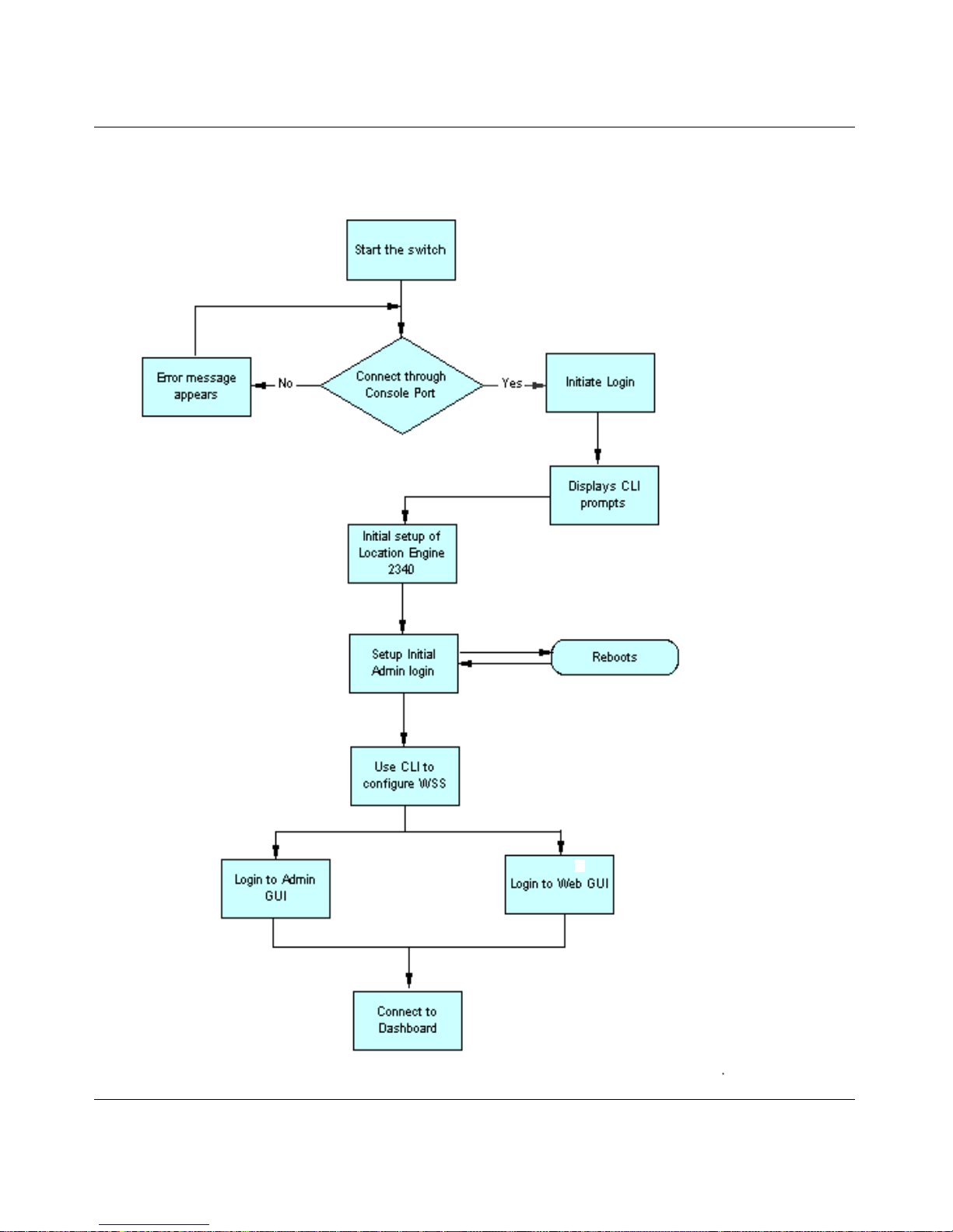
The Nortel WLE2340 Initial Administration GUI can be accessed through HTTPS.
Initial Administration GUI Access
To access the Nortel WLE2340's Initial Administration GUI through a secure connection, enter the following URLs into
your browser: https://<WLE2340_IP_Address>:8003.
Initiate Login
When you attempt to access the Nortel WLE2340 Administration GUI for the first time, it will offer a form for the first
user and password. This user is added to the admin role automatically.
Nortel WLAN Location Engine 2340 Initial Administration GUI . . . . . . . . . . . . . . . 21
Initial Administration GUI Access . . . . . . . . . . . . . . . . . . . . . . . . . . . . . . . . . . . . . . . 21
Initiate Login . . . . . . . . . . . . . . . . . . . . . . . . . . . . . . . . . . . . . . . . . . . . . . . . . . . . . . . . 21
Note. Before logging to Initial Administration GUI, you have to setup the WLE2340.
For more information about Setting up the Nortel WLAN Location Engine 2340, refer to
the ‘Software Installation’ chapter in Nortel WLAN — Location Engine 2340 Installation.
Note. When you enter the URL for the Nortel WLE2340, if you are redirected to a
page that displays the error message ‘HTTP Status 500’, it means that WLE2340 start has
not finished. Wait a moment, and then select the browser's refresh button.

22 Connecting to WLAN Location Engine 2340 through Initial Administration GUI
NN47250-504 (324122-A Version 01.01)
Logging in
The first attempt to access any GUI page redirects to a login page; the individual with overall system administration
privileges (typically the person with root privileges) can enter a secure user name and password. After the initial installa-
tion, a login screen is displayed once per session.
WSS configuration settings
WLE2340 detects location APs, once you perform the following steps:
Steps to set static ip address for APs:
#set ap <ap_number> boot-configuration switch mode enable
#set ap <ap_number> boot-configuration switch switch <switch IP address>
#set ap <ap_number> boot-configuration ip <ap_static_ip_address> netmask <netmask> gateway
<gateway IP address> mode enable
Steps to set snoop mapping (recommand snap-length is 100):
#set snoop <snoop name> oberserver <WLE-2340_ip_address> snap-length <snap-length>
#set snoop map <snoop name> ap <ap_number> radio <1 or 2>
#set snoop <snoop name> mode enable
You can use these commands to check snoop setting:
#show snoop stats
#show snoop info
Note. If you get the security check error ‘HTTP Status 400’ when you try to enter your
credentials, it means that Cookies are not enabled for the browser. In order to be able to log
in, you need to enable Cookies on the browser.
Note. In WSS, you have to first configure a static IP address for an AP to enable it in
WLE2340.

Connecting to WLAN Location Engine 2340 through Administrator GUI 23
Nortel WLAN - Location Engine 2340 Configuration - Using Interfaces
Connecting to WLAN Location
Engine 2340 through
Administrator GUI
Nortel WLAN Location Engine 2340 Administrator
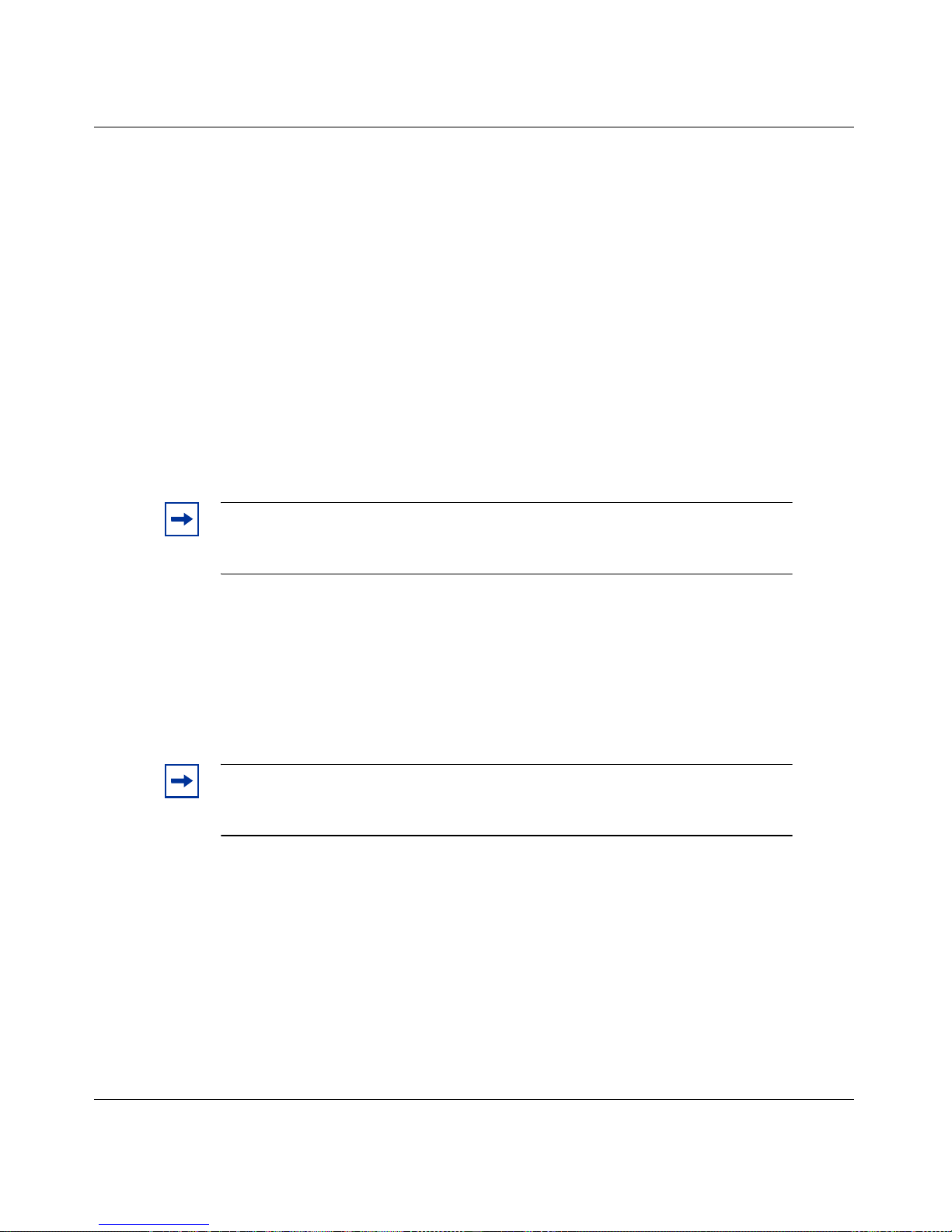
The System Administrator can add additional users to the admin group, each with their own username and password.
Doing this allows these users to access any page.
Creating a new administrator login using the system users page
To create the administrator login, follow the below steps:
1 Navigate to the System Users page and click Add.
2 Update the default name (New User) with the login name of the user. Enter the user's Full Name, the
password, and the password confirmation.
3 To give the new user administrative privileges:
• Select the Add Roles button, to display the Available Roles.
24 Connecting to WLAN Location Engine 2340 through Administrator GUI
NN47250-504 (324122-A Version 01.01)
• Select the admin role from the Available Roles.
• Click Add. The admin group appears in the Member Roles list.
4 Click Save. The default name ‘New User’ is updated.
Re-setting the admin password
To reset the admin password on the WLE2340 in the event of a forgotten password or other password change scenario,
you have WLE2340 console port access. To do this follow these steps:
1 Connect a serial cable to the WLE2340 console port.
2 Login at the console as ‘admin’ - password is not required.
3 Press a key (ESC) before being presented with the login prompt (2 second timeout).
4 Press the ‘Y’ key when prompted, to enter ‘Y’ to reset WLE2340 settings.
5 The admin password is then reset to the factory default.

Nortel WLAN Location Engine 2340 Web GUI 25
Nortel WLAN - Location Engine 2340 Configuration - Using Interfaces
Nortel WLAN Location Engine
2340 Web GUI
You can access the Nortel WLE2340 through web GUI. Once you enter the web GUI, you can access the following:
•Summary
• Monitor
• Calibration
• Configuration
• System
Launching the WLAN Location Engine Web GUI
To launch the WLE2340 Web GUI, follow the below steps:
1 To access the WLAN Location Engine Web GUI, enter the following URL in the browser:
https://<Web_IP_Address>.
The following screen appears.

26 Nortel WLAN Location Engine 2340 Web GUI
NN47250-504 (324122-A Version 01.01)
2 Enter Username and Password. The following screen appears.
3 You can access the following tabs by clicking on it:
• Summary
• Monitor
• Calibration
• Configuration
• System
Deploying the Location APs
Location APs capture the RF data during calibration and monitor the airwaves for 802.11-based devices and assets. This
chapter explains the following Location AP deployment tasks:
• Location AP Status
• Manual Location AP configuration
• Binding each Location AP to its respective Agent
Location APs
The Configuration > Location APs shows the list of registered Location APs and their status. Location APs that are
configured to use the Nortel WLAN Location Engine will begin to send detected wireless traffic to the WLE2340. The

Nortel WLAN Location Engine 2340 Web GUI 27
Nortel WLAN - Location Engine 2340 Configuration - Using Interfaces
Location AP list will show names (or IP address if the Location AP has not yet been given a name) and a status color as
shown below.
Green: The Location AP is responding frequently to server requests. If the number of devices seen by a Location AP
seems low (the number inside the green box), check the Location APs antenna connection.
Yellow: The Location AP has not responded for 10 seconds, indicating intermittent network coverage.
Red: The Location AP is not visible to the server, due to a network problem or malfunctioning or unplugged Location
AP.
After correcting a malfunctioning Location AP, refresh the page to verify that the status is green. If not, check with the
network administrator to verify that the network port is live. You can also use the Refresh Location AP Status at the
bottom of the page to get periodic updates of Location AP status.
Editing, adding, and removing Location AP
You can edit, add, and remove the location AP. To do this, follow the below procedures.
To edit an Location AP
1 Click on Location AP from the Location AP list.
2 The right hand pane will display a Name, Description and IP Address as shown below.
Edit the information and click Save.
3 You can assign a name, that indicates shorthand information about the Location APs location (such as
‘3rd Floor NE 1’). The description filed can be used to add even more detailed information, such as
Above Accounts Payable desks.

28 Nortel WLAN Location Engine 2340 Web GUI
NN47250-504 (324122-A Version 01.01)
4 Click Save to keep the changes.
To add a Location AP
It may be necessary to manually add a Location AP.
1 Click Add. The window appears on the right hand pane.
2 Enter the Name, Description and IP Address.
3 Click Save.
To remove a Location AP
1 To remove a Location AP, highlight the name of the Location AP from the list.
2 Click Remove.
Associated agent
The Nortel WLAN Location Engine has one Agent process and all Location APs can be associated with it automatically.
However, it may be necessary to configure this manually.
Assigning Location APs to an Agent on the Tracking Agents
1 Select Configuration>Agent. The Agent Information panel updates to include the information for the
selected Agent. The following window appears.
Note. Performance can suffer if there are Location APs listed that are no longer
reporting. Keep the Location AP list up to date with the actual Location APs that are
reporting back to the Nortel WLAN Location Engine.

Nortel WLAN Location Engine 2340 Web GUI 29
Nortel WLAN - Location Engine 2340 Configuration - Using Interfaces
2 Select Add Location AP. The Available Location APs dialog appears.
3 Select the Location APs>Add. The Location APs Assigned to This Agent list box populates.
Placement guidelines
The number of Location APs you can install is determined by a site survey conducted by Nortel. It is based on the size of
the area to be secured and the type of tracking precision required. But regardless of the number of Location APs or
tracking precision, there are two general guidelines for how Location APs can be positioned in relation to one another:
• A Location AP can not be placed such that two locales are mirror images of one another with respect to the
Location AP. The goal is to create as much asymmetry as possible. To achieve this goal, Location APs can be
placed in corners of rooms, rather than the center, and in corners of locale clusters, rather than the center.
Note. Before closing the page, make sure the Agent is Enabled.

30 Nortel WLAN Location Engine 2340 Web GUI
NN47250-504 (324122-A Version 01.01)
• Location APs must be placed away from large metal objects, such as elevator shafts, and closer to ceiling height in
order to minimize interference from human traffic.
The following three scenarios elaborate on these general guidelines. Each scenario shows an incorrect placement along
side a correct placement. The incorrect placement results in two locales appearing identical to the Location AP. The
correct placement moves the Location AP to create asymmetrical views of the two locales.
Scenario 1
Placing a Location AP in the middle of the border between Locale 1 and Locale 2 makes the two locales appear identical
to that Location AP. Moving the Location AP to an outside edge, as in the diagram on the right, removes this symmetry,
creating a distinct RF pattern for Locale 2.
Scenario 2
Placing 1 Location AP in the center of Locale 2 and another in the center of Locale 3 makes Locale 4 look like Locale 1.
Moving the Location APs to the positions indicated in the diagram on the right removes this symmetry, creating a
distinct RF pattern for Locale 4.
Note. The location of existing Location APs may be set up in contradiction to the
recommendations here - for instance, highly symmetrical and in the center of Locales. Even
staggering by as little as 5 meters can be enough to avoid the kind of symmetry mentioned
in this section.

Nortel WLAN Location Engine 2340 Web GUI 31
Nortel WLAN - Location Engine 2340 Configuration - Using Interfaces
Scenario 3
The Location AP placement in the diagram on the left results in Locale 1 and Locale 6 having identical RF fingerprints.
The diagram on the right corrects the problem.
Calibrating the Tracking Engine
Once the Location APs are deployed the next step is to capture the RF data which, the Nortel WLAN Location Engine
uses to identify each locale in the area under surveillance. This process is referred to as calibration.
The calibration of your site is an iterative process:
1 Create enough RF fingerprints to achieve the granularity of device tracking you require in each part of the
area under surveillance:
• inside or outside the physical perimeter
• in a department
• in a room.
2 Use the Evaluator to examine the calibration for problems such as,
•missing data
• conflicting data
• inconsistent data
3 Walk-through the site with a wireless device and note those locales in which either of the following
occurs:
• you need to walk too far into a locale before the Tracking Engine recognizes the new position of
the device (latency)
• the Tracking Engine tracks the device to the wrong locale (accuracy).

32 Nortel WLAN Location Engine 2340 Web GUI
NN47250-504 (324122-A Version 01.01)
These problems can be addressed, as outlined in 'Fine-tuning the Tracking Engine' chapter, and then the Evaluator can be
rerun and another walk through performed.
This chapter explains the following:
• Choosing and naming locales.
• Selecting the channels on which to scan during calibration.
• Creating and capturing RF fingerprints.
• Running the Evaluator to determine the usefulness of the captured data.
• Selecting the 802.11 band(s) to monitor for the walkthrough.
• Verifying device tracking with a walkthrough.
Locales
Each locale needs to be named, so that the name is available for binding the RF fingerprints which form the locale's
fingerprint when the calibration process begins. Locale names can correspond to the actual areas, that you are tracking
(e.g. Conference Room, Lobby, or Warehouse 1).

Nortel WLAN Location Engine 2340 Web GUI 33
Nortel WLAN - Location Engine 2340 Configuration - Using Interfaces
Creating Locales on the Calibration Locales page
1 Select Calibration>Locales to display the currently defined locales. Highlighting a locale name
populates the Locale Information column as shown below.
2 Click Add. The default name New Location appears in both columns, and RF fingerprint binding
controls appear in the Locale information column.
3 The Locale Information Column contains a Bound RF Fingerprints panel for binding (associating) RF
fingerprints to locales. RF fingerprints can be bound here, or after calibration on the Calibration RF
Fingerprints Page.
In the Locale Information column, replace the default name ‘New Location’ with the actual name of the
locale, and enter an optional Description. It is helpful to use a naming convention that makes it easy to
distinguish between locales and RF fingerprints.
4 Click Save.
It is also possible to Import a list of Locale names and descriptions. The format for the file is XML, but the import file
may be named as either an XML or TXT document. The format for the Import file is as follows:
Note. The preconfigured generic locale named -Elsewhere-, which refers to
areas that do not match any of the existing RF fingerprints.

34 Nortel WLAN Location Engine 2340 Web GUI
NN47250-504 (324122-A Version 01.01)
Use as many locale elements as desired.
Channel scanning
When calibrating, Location APs can scan the same channel that the Access Points scan. (After Nortel WLAN Location
Engine is fully deployed and operational, Location APs can be set to scan on one or more 802.11 bands).
RF Fingerprints
The Calibration RF Fingerprints page allows you to name RF fingerprints and bind them to locales without capturing the
RF data required for calibrating the Tracking Engine. This allows the capturing of RF fingerprint data to be handled by a
different person from the person who is selecting the locale and RF fingerprint names. An RF fingerprint is considered
empty until the RF data that characterizes it has been captured.
To capture RF data for each RF fingerprint, the personnel responsible for the calibration phase of the deployment can
physically walk through the area to be monitored. Nortel recommends holding a wireless device broadcasting on the
scanned channel. If the device cannot open a browser page to the Nortel WLAN Location Engine Console, then a second
device or individual must initiate the calibration process through the Nortel WLAN Location Engine Console.
Note. The description attribute can be blank, but each name can have a value.
Note. Before capturing RF fingerprints, create network traffic by starting a
continuous ping between the wireless client and the server.

Nortel WLAN Location Engine 2340 Web GUI 35
Nortel WLAN - Location Engine 2340 Configuration - Using Interfaces
Using the Calibration RF Fingerprints Page
After entering the admin user name and password established at installation, repeat the following procedure for each RF
fingerprint to capture the RF fingerprint data:
1 Select the Calibration>RF Fingerprints. The following window appears.
2 If the RF fingerprint to be captured was previously created, select it from the left panel. It was not
previously done, then click Add. The default name New RF Fingerprint appears in both columns, and
calibration controls are added to the RF Fingerprint Information column.
3 In the RF Fingerprint Information column, replace the default name New RF Fingerprint with a name
that describes the location of the RF fingerprint, for example mailroom-nw.
4 Select the correct Locale from the Bound to Locale drop down list. An RF fingerprint can be bound to
only one locale.
5 Enter the MAC Address of the wireless device being used to calibrate, as hex pairs separated by a colon
(:).
6 Click Start. The message ‘Buffering...’ displays, after which a flashing Progress label indicates the
percent complete, and a graph shows the signal strength for the RF fingerprint as seen by each Location
AP.
Note. If the buffering continues for more than 60 seconds, make sure the correct MAC
address is entered.

36 Nortel WLAN Location Engine 2340 Web GUI
NN47250-504 (324122-A Version 01.01)
The Location APs you have installed (within a 300' radius of the calibration device) can be shown in the graph. If any are
missing, select Cancel and navigate to the Configuration -> Location APs page to evaluate the problem before
restarting calibration.
7 Capturing RF data for a RF fingerprint is a brief two part process in which you first stand in the center of
the RF fingerprint, and then walk a circle:
• For the first half of the calibration period (as measured by the flashing Progress label), stand
in the center of the RF fingerprint and slowly ‘turn’ in place, rotating a full 360 degree. The
reason you turn in place is to account for variations in the data caused by an RF shadow (i.e. a
surface, such as a girder, column, elevator shaft, stairwell, or even a human body). RF shadows
occlude the RF signal measured by a particular Location AP, distorting the representation of
the space the Nortel WLAN Location Engine Tracking Engine creates during calibration. By
turning in place, you ensure that the Nortel WLAN Location Engine Tracking Engine creates a
very strong representation of the center of the RF fingerprint.
• For the remaining 50% of the calibration (as indicated by the flashing Progress label), walk in
a circle, to vary the signal strengths received by nearby Location APs. The size of the circle for
smaller spaces, like offices, can be roughly one-third of the floor space. For example, in a
300 sq ft conference room, the circle you traverse can cover approximately 100 sq ft. For
spaces larger than 500 sq ft, the diameter of the circle can stay fixed at 15 ft, regardless of how
large the RF fingerprint is. Your rough sense of these proportions is good enough and you
don't need to measure the circle you traverse. After the calibration interval is completed (as
signaled by flashing Progress label), the RF Fingerprint Quality is displayed as follows:
❍ Excellent
❍ Good
❍ Fair
❍ Poor.
If the quality is not Excellent, it means that the quality of the data collected by the WLE2340 was not
sufficient to create an accurate fingerprint of the space, and you can recapture data for the RF Fingerprint.
8 Click Save.

Nortel WLAN Location Engine 2340 Web GUI 37
Nortel WLAN - Location Engine 2340 Configuration - Using Interfaces
It is also possible to Import a list of RF Fingerprint names and descriptions. The format for the file is XML, but the
import file may be named as either an XML or TXT document. The format for the Import file is as follows:
Use as many signature elements as desired.
Evaluating Calibration
After calibration is complete, an evaluation report can be created on the Calibration Evaluation page. Select the Locales
to evaluate and then select the Run Evaluator.
Note. The description attribute can be blank, but each name can have a value,
and the type attribute can always be signature.

38 Nortel WLAN Location Engine 2340 Web GUI
NN47250-504 (324122-A Version 01.01)
The report shows the evaluation for each locale selected. For example, here is a sample report for the 3 different Locales:
The report flags following types of problems and indicates the fix:
• Malfunctioning Location APs, not enough Location APs
• RF Fingerprints the Tracking Engine has trouble distinguishing
• Human error (e.g. RF fingerprints that are too large/small, duplicate, or for which no RF data was captured). Before
moving on to the walkthrough stage, problems can be addressed and the report rerun until the report indicates that
there are no problems.
The following sections elaborate on the causes and suggested responses to each of the problems the Evaluator is able to
catch.
Location APs malfunctioning
This error appears if a Location AP that can be reporting has failed to deliver consistent data.
Empty RF Fingerprints
The Calibration RF Fingerprints page allows you to name RF fingerprints and bind them to locales before calibration, so
that the capturing of RF Fingerprint data can be handled by a different person from the person who is selecting the locale
and RF Fingerprint names. This opens up the possibility that some RF Fingerprint names will be entered into the system
but the Tracking Engine will lack the required RF data. If this happens, then the missing RF Fingerprint data can be
captured.
Duplicate RF Fingerprints
Duplicate RF fingerprints are the result of two types of human error:
• Two of your personnel have independently captured RF data for the same RF Fingerprint
• Calibration is occurring at a date after the names have been entered and bound to locales, and the wrong RF
Fingerprint is selected from the drop down list (e.g. the person is in Conference Room A, but selects Conference
Room B from the list). In the first instance, all duplicate RF fingerprints can be deleted; in the second, the RF
Fingerprint can be bound to the correct locale and new data captured.

Nortel WLAN Location Engine 2340 Web GUI 39
Nortel WLAN - Location Engine 2340 Configuration - Using Interfaces
RF Fingerprints too large
While capturing RF Fingerprint data during calibration it involves the following two distinct motions:
• standing in the center of the RF Fingerprint for the first half of the calibration interval
• walking in a circle for the second half.
If the circle traversed during the second part of the calibration interval is larger than 15 ft in diameter, then the Evaluator
will flag the RF Fingerprint as being too large. If you really want to secure the entire area traversed during the original
calibration, then split the RF Fingerprint into an appropriate number of smaller RF fingerprints. Else, recalibrate making
sure that the diameter of the circle traversed for the offending RF Fingerprint is not greater than 15 ft.
Two RF Fingerprints appear to be the same
When the Nortel WLAN Location Engine Tracking Engine isn't able to distinguish between two RF fingerprints in
different locales, the Evaluator flags this as critical because you may experience tracking inaccuracies and performance
degradation.
For either of these RF Fingerprint overlap conditions, a number of factors can be evaluated before choosing the correct
fix, and so the Evaluator does not indicate a specific fix.
Walk-Through
To test the ability of the Nortel WLAN Location Engine Tracking Engine to transition you from one locale to another,
based on the RF Fingerprint data collected during the Calibration phase, you walk through all locales holding a wireless
device.
Simply connect to the Nortel WLAN Location Engine Console and the Monitoring section to see where the device is
tracked during the walk-through (see 'Fine-tuning the Tracking Engine' chapter on Monitoring for more details).
When you cross the boundary between two locales, the Server can shortly update the web page with the new locale and
RF Fingerprint. If it takes too long, or if the wrong location is displayed, make a note of the trouble spot and move on.
Once the entire walk-through is finished, follow the instructions in 'Calibrating the Tracking Engine' chapter to identify
the cause of these problems and choose the proper fix.
Note. If an RF Fingerprint is still flagged as being too large after recalibration, it
likely means that there is some type of obstruction nearby, such as an elevator
shaft, not that the person traversed too large a circuit during the original
calibration. Obstructions will produce this type of error, because they cause a
dramatic drop in the signal strength coming from the calibration device, making the
Nortel WLAN Location Engine Tracking Engine think that the person has walked
too far from the center of the RF Fingerprint. To fix this problem, you may need to
add another Location AP to compensate for the interference being caused by the
obstruction.

40 Nortel WLAN Location Engine 2340 Web GUI
NN47250-504 (324122-A Version 01.01)
Fine-Tuning the Tracking Engine
Running the Evaluator and fixing the flagged problems (as described in Section 0) eliminates many potential problems
with device tracking. Some problems cannot be detected without physically walking through the space under surveillance. As you move through locales during the testing phase, the Nortel WLAN Location Engine Tracking Engine can
recognize the locale and RF Fingerprint you are in within 60 to 90 seconds of your arrival. If it takes longer (i.e. unacceptable latency), or if the wrong RF Fingerprint and locale are reported, the first approach can always be to recalibrate,
capturing new RF data for the problem RF fingerprints. This will correct problems with the original calibration data
created by transient RF anomalies, network outages, or human error.
If recalibration does not correct the problem, then consult the appropriate section of this chapter to address the problems:
• Adjacent locale misreported.
• Wrong side of border reported.
• Distant locale misreported (because of RF resemblance to actual locale).
Adjacent Locale misreported
If the Nortel WLAN Location Engine Tracking Engine incorrectly reports your position as being in an adjacent locale,
your first approach can be to make sure that there are RF fingerprints on either side of the transition point between the
two locales.
Wrong side of border reported
If you are standing near the edge of a locale, and the Nortel WLAN Location Engine Tracking Engine can't determine
whether you are just inside or just outside the locale, the position reported by the Tracking Engine bounces back and
forth between the locale in which you are physically standing and the adjacent locale. To correct this problem, try adding
or recalibrating RF Fingerprints. In addition, it may be helpful to add a Location AP and then recalibrate.
Distant Locale misreported
On occasion, unusual RF dynamics in a building artificially make two locales appear identical, even though they are
physically distant from one another. For example, any time a device enters a locale named ‘Conference Room A’, its
locale is always misreported as ‘Lunch Room,’ even though Conference Room A and the Lunch Room are on different
floors.
You can add two Location APs as follows:
• One in the correct locale
• Another in the misreported locale.

Nortel WLAN Location Engine 2340 Web GUI 41
Nortel WLAN - Location Engine 2340 Configuration - Using Interfaces
Monitoring the Wireless Network
The Nortel WLAN Location Engine Console provides the following snapshots of live device activity:
• Summary page: An overall system summary.
• Device List page: A table which presents a single detail line for each device. You can display following two pages
from the Device List page:
• Device Detail page: An exhaustive listing of a single device's characteristics.
• Device History page: A chronological list of a single device's transitions between locales.
• Summary page: An overall system summary.
• Alert Page.
Summary page
The Summary page presents an overall system summary which indicates:
• Device Summary: The number of Access Points, Clients, and devices in ad hoc mode. Nortel certified asset tags are
enumerated separately from clients as another device type. Consult with Nortel Professional Services for supported
list of certified asset tags.
• Network Summary: The number of networks, clients associated with a network, and unassociated devices.
• Device Summary (Nortel WLAN Location Engine devices): The number of Agents and Location APs.
Device List page
The Device List Page presents a table that contains 1 row for each device. If the device list is short enough, visually scan
the page to locate devices of interest. Otherwise, reduce the scope of the list or focus on devices of interest:
• Filter the page: Filter to include only those devices that have a specific filter string in any of the columns. For
example, you can filter the list to include only those devices that have the string ‘CLIENT’ or ‘ACCESS POINT’ in
the Type column, or the string ‘LOBBY’ in the Locale column.
• Sort the page: Sort on any column, to change the order in which devices are listed. The columns are as follows:

42 Nortel WLAN Location Engine 2340 Web GUI
NN47250-504 (324122-A Version 01.01)
•Label
• Type
• Network Info
• Locale
• MAC Address
•IP Address
•Last Seen
For example, clicking on the Device Type column causes the devices to be sorted by device type:
• Access Points first
• Clients second and so on.
• Eliminate Active/Inactive: Reduce the scope of the list from ‘All Devices’ to either ‘Only Active Devices’ or ‘Only
Inactive Devices’. An active device is one which is powered on and has transmitted within the time specified by the
Inactivity Time parameter (140 seconds).
Once a device of interest has been located on the page, the user can:
• See more detail for a device: Select the next to the device's label to display the Device Detail page.
• See history for a device: Select the next to the device's label to display the Device History page.
• Edit a device's information: Select the next to the device's label to display the Device Information dialog.
• See other clients on same Access Point: For each CLIENT device associated with an Access Point, the MAC
address shown in the Network Info Column is a link. Click on the MAC address to redisplay the Monitor Device
List page showing just the devices communicating with that Access Point.
For example, see below the Device List page filtered to include only active devices that contain the text ‘Labs’ in any
column:
To edit device information, use the Device Information dialog.
Using the Device Information dialog to assign a Device Label
1 Select Monitor>Device List page.

Nortel WLAN Location Engine 2340 Web GUI 43
Nortel WLAN - Location Engine 2340 Configuration - Using Interfaces
2 Filter the page to display only those devices that have a specific filter string in any of the columns. For
example, you can filter the list to include only those devices that have the string ‘CLIENT’ or ‘ACCESS
POINT’ in the Type column, or the string ‘LOBBY’ in the Locale column.
3 Reduce the scope of the list from ‘All Devices’ to ‘Only Active Devices’ or ‘Only Inactive Devices’. An
active device is one which is powered on and has transmitted within the time specified by the Inactivity
Time parameter.
4 Select the next to a device's label. The Device Information dialog for that device appears.
5 The default label used by the system to identify all devices on the Administrative Console is the MAC
address. To make it easier to identify devices on console pages and in reports, replace the default label
with one that is more descriptive, for example ‘Lobby AP’.
6 Click Save.
Device Detail page
To display the Device Detail page for a device on the Device List page, select the next to the device's label. The type
of information presented on the Device Detail page depends on whether the device is a Client or an Access Point.
The Current Status panel at the top of the Device Detail page presents a snapshot of the device's characteristics:
•label
• locale
• MAC address
• network info
• vendor
•RF fingerprint
• IP address
• channel
The tabs displayed at the bottom of the Device Detail present information that enables the System Administrator to
analyze how the device has been used since it entered the location. Regardless of the device type, the Activity tab and
Recent Locales tab always appears. If the device is an Access Point or a device in Ad Hoc mode, one additional tab
appears - the Associated Devices tab. For all other device types, the Network Info tab appears.

44 Nortel WLAN Location Engine 2340 Web GUI
NN47250-504 (324122-A Version 01.01)
Associated Devices
When the device presented on the Device Detail page is an Access Point or device in Ad Hoc mode, the page displays
with an Associated Devices tab, which presents a table that contains a single line for each client associated with the
Access Point.
Activity
For all device types, the Activity tab displays a table which contains one row for each period the device was active or
inactive, making it easy to determine if a particular wireless card is enabled and transmitting. If a device is currently
active, the time the device starting transmitting and the total elapsed time is shown. If a device is currently inactive, the
time its transmissions ended is also shown. (An active device is one which is powered on and has transmitted within 140
seconds.)
Recent Locales
The Recent Locales tab presents a table containing one line for every locale the device has been in since it began transmitting. For each locale the device has passed through, the system shows the time the device was detected in that locale,
the time the device left that locale, and the total time the device was in that locale.
Network Associations
The Network Associations tab presents a table containing one line for every network with which the device has been
associated. The time the device first appeared on the network, the time it left the network and the total time on that
network are shown
Once the device's wireless card has connected to network, the string ‘via’ and the MAC address of the Access Point
appear in the network Info column. If the string ‘Closed Network’ appears in the Network Info column, it means the
ESSID is not being broadcast.
Device History page
The Device History page is a chronological list of a single device's transition events (i.e. moving from one locale to
another).

Nortel WLAN Location Engine 2340 Web GUI 45
Nortel WLAN - Location Engine 2340 Configuration - Using Interfaces
To display the page, select on the Device List or Device Details pages
By default, just the most recent 24 hours of transition events are shown. To display the history for a different time
period, enter new start and end dates and times. You can also display the history for a different device by entering the
MAC address for that device.
Alert List
The Monitor Alert List page will show any current System Alerts and also offers a form to query alerts during specific
periods of time.
There are two categories of system alerts currently supported in the Nortel WLAN Location Engine:
• Internal system alerts.
• Asset tag telemetry alerts.
For more information on alerts, refer ‘Configurating Notifications and Alerts’ chapter.

46 Nortel WLAN Location Engine 2340 Web GUI
NN47250-504 (324122-A Version 01.01)
Configuring Notifications and Alerts on WLAN Location
Engine 2340 Web GUI
This chapter explains how to:
• Choose a notification mechanism (email, syslog, or SNMP trap).
• Specify syslog properties.
• Specify e-mail properties.
• Specify SNMP properties.
• Configure the System Alerts to use the established Notification mechanisms.
Email, Sysleading2og, and SNMP Trap
System Alerts are classified as follows:
• Critical
•High
•Medium
•Low
•Info.
Each type can be delivered by one or all three of the following:
•email
• syslog
• SNMP V2 or V3 trap.
Use the System Settings Page and Notifications Tab to Enable Notifications
for Alert Levels
1 Navigate to the System Settings page and select the Notifications tab.
2 Specify the base URL for alerts. The URL can have the form https://<IP_address_of_Location Engine>

Nortel WLAN Location Engine 2340 Web GUI 47
Nortel WLAN - Location Engine 2340 Configuration - Using Interfaces
3 For each priority level of alert choose one or more delivery mechanisms by selecting any combination of:
Email1, Email2, Email3, SNMP1, and SNMP2.
Specifying Syslog properties
Using the System Settings Page as shown below, Notifications Tab to Specify Syslog Properties
• Syslog Hostname: The IP address of syslog server
• Syslog Facility Name: The facility to which alerts are sent, usually local3
48 Nortel WLAN Location Engine 2340 Web GUI
NN47250-504 (324122-A Version 01.01)
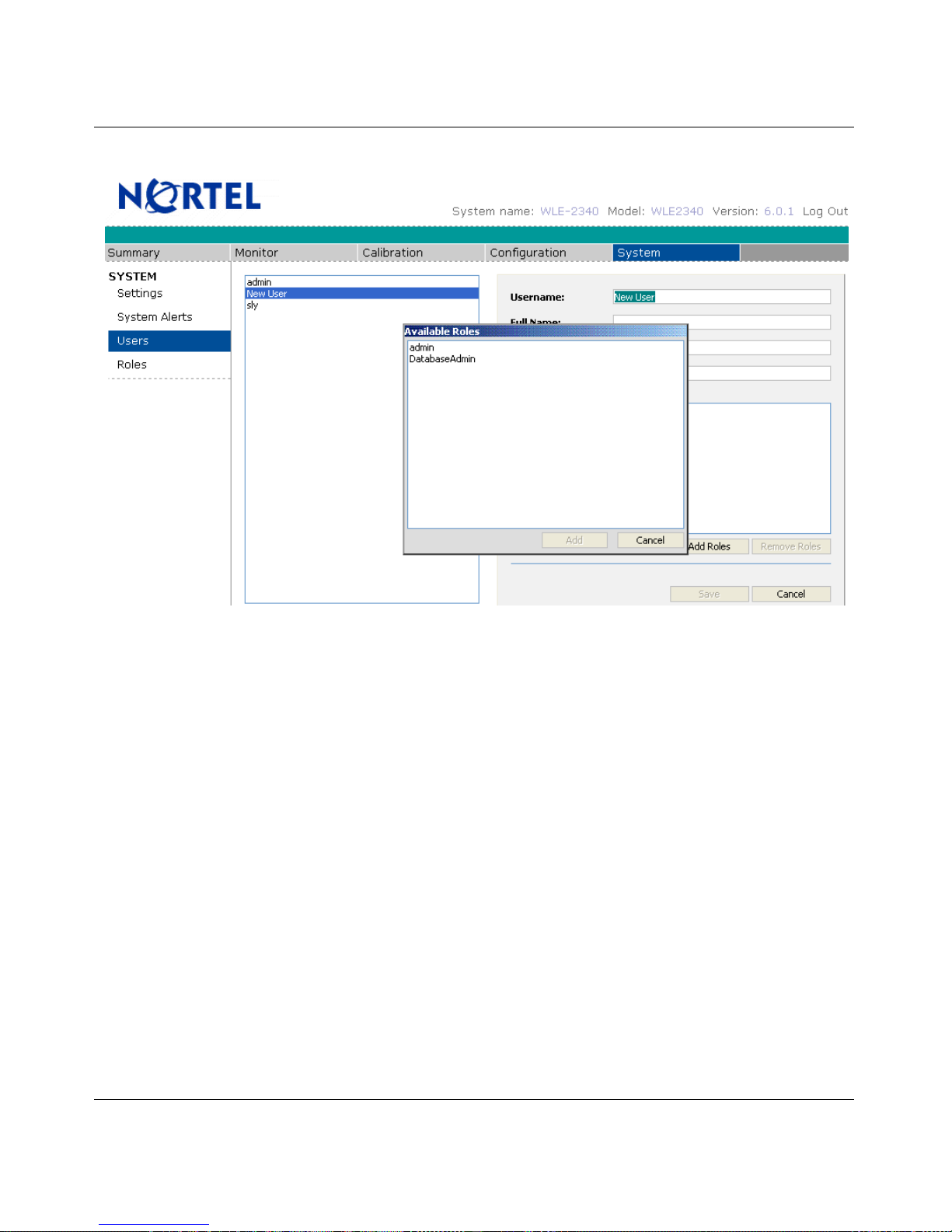
Specifying E-mail properties
Alerts can be delivered to 3 email addresses as shown below.
• SMTP Host: The IP address of the mail server.
• Email Recipient: The email address that can receive all email alerts.
• Email Name Suffix: The suffix that can be appended to the email name.
• Reply-To Address: The email address that can appear in the header of the alert.

Nortel WLAN Location Engine 2340 Web GUI 49
Nortel WLAN - Location Engine 2340 Configuration - Using Interfaces
Specifying SNMP properties
Using the System Settings Page, Notifications Tab to Specify SNMP Trap Properties as shown below.
SNMP1 and SNMP2
• Destination Host: The IP address of the machine which can receive the trap.
• Destination Port (default is 162): The default can be accepted.
• SNMP Version: Select the version in use, either v2c or v3.
• SNMP Community (specify only if using SNMP Version 2c): Specify the same community name here as on the
destination host.
SNMP Version 3
• Use Authentication: Check to guarantee that the trap is coming from the Nortel WLAN Location Engine (to thwart
spoofing).
• Use Privacy/Encryption (Requires Authentication): Check to guarantee that the trap cannot be intercepted.
• Authentication Protocol: Specify the same protocol as on the destination host.
• Username: Any valid username on the destination host.
• Authentication Pass phrase: Set only if Use Authentication is checked.
• Privacy Pass phrase (Defaults to Authentication Pass phrase): Specify a secure password only if Use Privacy/
Encryption is checked.
• Context Engine ID: Any ID except one for another originator of traps.
• Context Name: Not currently used.

50 Nortel WLAN Location Engine 2340 Web GUI
NN47250-504 (324122-A Version 01.01)
System Alerts
The available System Alerts are listed in the table below:
Table 1: System Alerts
Name Description Response
P
arameters
Agent Down The Agent process is
responsible for device
tracking. If the Agent
process is unavailable,
then device location will
not be updated.
Check the Agent through
the Console interface
and resolve any issues.
Reboot the WLE2340 to
re-start the Agent
process.
N/A
Location AP Down A registered Location
AP is not visible to the
server, due to a network
problem or a
malfunctioning or
unplugged device.
Inspect Location AP
and/or network to
determine source of
problem. After
correcting a
malfunctioning Location
AP, refresh the
Configuration ' Location
APs page to verify that
the S status is green. If
not, check with the
network administrator to
verify that the network
port is live.
N/A
Location AP Up A previously unavailable
Location AP is now
registered and available.
N/A N/A
Asset Tag Button Press Asset tag button has
been pressed.
Asset Tag Detached Asset tag indicates it has
been detached.
Asset Tag Low Battery
War nin g
Asset tag battery drops
below N days.
Retrieve specific asset
tag and replace the
battery accordingly.

Nortel WLAN Location Engine 2340 Web GUI 51
Nortel WLAN - Location Engine 2340 Configuration - Using Interfaces
Configuring Alerts
To configure the alerts
1 Navigate to the Settings >System Alerts page. The table on the page lists the system alerts that have
already been turned on (if any). The below figure shown the Location AP Down alert is configured
already.
2 Click Add Alert… to add a new Alert. The Alert Configuration Dialog appears.
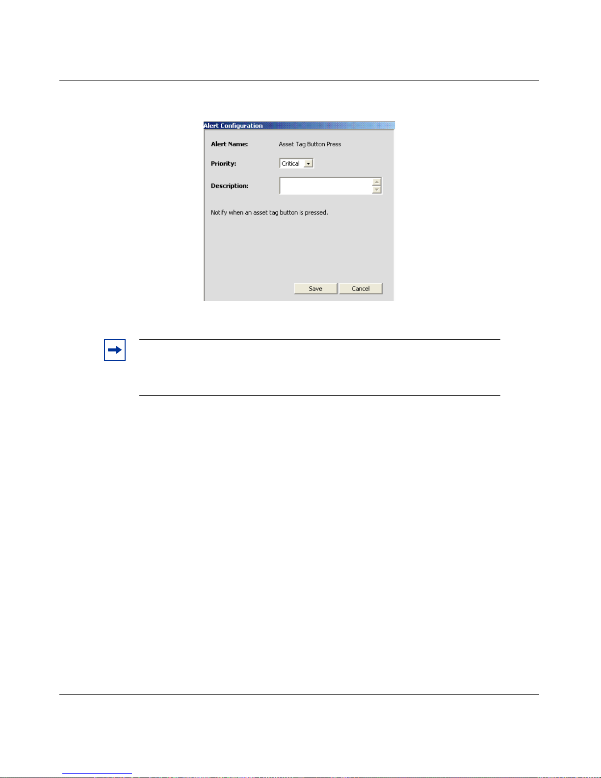
52 Nortel WLAN Location Engine 2340 Web GUI
NN47250-504 (324122-A Version 01.01)
3 Select an alert to configure from the list and click Next>> to continue. A properties window for the alert
appears.
4 Select the Priority from list and click Save.
Note. Alerts are removed from the Alert Configuration dialog list if they are
already configured. If all System Alerts are configured, then the Alert
Configuration dialog may show an empty list. The next section discusses how to
edit or remove existing alerts.

Nortel WLAN Location Engine 2340 Dashboard 53
Nortel WLAN - Location Engine 2340 Configuration - Using Interfaces
Nortel WLAN Location Engine
2340 Dashboard
The Nortel WLE2340 Dashboard relies on a Nortel WLE2340 to supply the device, locale, and network information. It is
used in the Dashboard's live depictions of network coverage and device location. Once you install the Nortel WLE2340
for the first time, you need to establish a connection to the Nortel WLE2340. At each subsequent startup of the Nortel
WLE2340 Dashboard, the connections are re-established automatically.
Hardware requirements
For Windows, the recommended standard configuration for each machine are as follows:
• Pentium III 1.0 GHz
• 512 MB RAM
• 200 MB free disk space
Software requirements
Following are the Certified Operating Systems:
• XP Service Pack 2
• Microsoft Windows 2000
Connecting through HTTPS
You can establish a connection from the Nortel WLE2340 Dashboard to a Nortel WLAN Location Engine through
HTTPS. To connect, follow the below steps:
1 Select or File>Add Server Connection. The Enter Connection Details window appears.

54 Nortel WLAN Location Engine 2340 Dashboard
NN47250-504 (324122-A Version 01.01)
In the Server Address, enter the URL of the Nortel WLE2340 UI or Platform Web UI through a browser. DNS can be
established for the WLE2340 for the dashboard to connect successfully. The DNS entry used can correspond to the name
specified in the ‘Configure Networking’ page of the Nortel WLAN Location Engine Administration UI.
Example: For connections to a Nortel WLE2340:
https://<Appliance_IP_Address>
2 Enter the Username and Password.
3 Click Connect. The Initializing Server Connection wizard appears. During the connection process,
information about the devices, locales, and networks being tracked by the Nortel WLAN Location Engine
is loaded into the Dashboard.
4 Click plus sign (+) to expand the hierarchy. Following options are available:
• Layouts - Shows all the layouts, you have created previously with the Dashboard. A layout is a
floor plan (map), on which the Dashboard depicts live views of network coverage, device
location, and Access Point associations
• Locales - Shows the locales tracked by the server.
Note. You can use the DNS name instead of the IP address of the Nortel WLAN
Location Engine (if enabled).
Note. Once the connection has been completed, the connection URL appears in the
Connections panel.

Nortel WLAN Location Engine 2340 Dashboard 55
Nortel WLAN - Location Engine 2340 Configuration - Using Interfaces
• Networks - Shows the networks tracked by the server.
Device lists
Once the connection is established from the Nortel WLE2340 Dashboard to a Nortel WLAN Location Engine, you
following table immediately appears:
The Device List presents a comprehensive summary of the each device as follows:
•label
• device type
• network info
•group
• channel
• locale
• MAC address
• IP address
•Activity
A Device List can be displayed for any of the following by right clicking on the name in the Connections panel and
selecting View Devices from the context menu:
• Server: All devices being tracked (i.e. on all networks and in all locales).
• Locale: Just the devices in the selected locale.
• Network: Just the devices in the selected network
By default, all powered devices within range of the specified wireless network are listed. The list can also be filtered to
show just active or inactive devices. (An active device is one that is powered on and has transmitted within the period
specified by the Inactivity Threshold parameter, by default 140 seconds).
Label refers to the name assigned to the device in the Nortel WLE2340; if name was not assigned, then the default label
will be MAC address. Device Type can be Client, Access Point, Ad Hoc or UNKNOWN. Network Info displays the
Note. When you close the Nortel WLE2340 Dashboard, the connection will be
automatically saved and are re-established automatically on start up. It will prompt for
password during re-connect if the Save password check box was not checked during login.

56 Nortel WLAN Location Engine 2340 Dashboard
NN47250-504 (324122-A Version 01.01)
ESSID that each device is broadcasting (if available); if the report indicates ‘Closed Network’ for a particular device, it
means the ESSID is not being broadcast.
Filtering the list
There are four filtering controls (lists) at the top of the tab as follows:
• Locale: display the devices only for the specified locale (grayed-out when the Device List was generated for a
single Locale)
• Network: display the devices only for the specified network (grayed-out when the Device List was generated for a
single Network)
• All/Active/Inactive Devices: display all devices/active devices only/inactive devices only
• Label/MAC: display the devices whose Label/MAC contains the specified alpha-numeric string
For more information on Creating the layout, see the chapter ‘Creating the layout’.
Using the Nortel WLAN Location Engine 2340
Dashboard
Installing WLAN Location Engine Dashboard on windows systems
1 Insert the WLE2340 CD in the CD-ROM drive. Locate the dashboard directory and choose the
sub-directory for the OS, where the Dashboard has to be installed (Windows). The Introduction wizard
appears.

Nortel WLAN Location Engine 2340 Dashboard 57
Nortel WLAN - Location Engine 2340 Configuration - Using Interfaces
2 Read and accept the License Agreement. The Choose Install Folder wizard appears.
3 Click Choose and browse the path to install the software under required drive. You can enter the complete
qualified path of the new directory. The path cannot contain spaces.
Select Restore Default Folder to re-enter the default directory in the text field.
4 Click Next or select Choose Shortcut Folder. The Choose Shortcut Folder wizard appears.
You are prompted: Where would you like to create product icons?
Choose one of the following:
• In a new program Group
• In an existing program group
• In the start menu
• On the Desktop.
• In the Quick Launch Des
•Other

58 Nortel WLAN Location Engine 2340 Dashboard
NN47250-504 (324122-A Version 01.01)
• Don’t create icons
5 Click Next or select Pre-Installation Summary. The Pre-Installation Summary wizard appears.
6 Click Install. Once the installation is complete, Click Done.
Creating a layout
A layout is a map or floor plan of an area where devices are tracked with the Nortel WLAN Location Engine. For
example, if your organization is housed on 6 floors of a 10 story building, you can create 6 layouts.
The layout in and of itself is a building block: it serves as the backdrop against which the Nortel WLE2340 Dashboard
depicts live views of the Wi-Fi activity in the physical area represented by the layout.
To create a layout
1 Use the Layout wizard and import a floor plan image (gif, jpeg, or png).
2 Use the Locale Rectangle Tool or Locale Freeform Tool to draw the Locales on the layout. Associate
the drawn locales with the actual locales tracked by the WLE2340.
3 Use the RF Fingerprint and Sensor tools to place icons on the drawn locales and associate those icons
with the actual RF Fingerprints and Sensors in those locales. (Each locale is associated with one or more
RF fingerprints. The Nortel WLAN Location Engine matches the RF fingerprint of a device to the
fingerprints it has on file for each locale in order to accurately determine the locale of each device.)
4 Use the Scale Tool to indicate the scale of the drawn locales.

Nortel WLAN Location Engine 2340 Dashboard 59
Nortel WLAN - Location Engine 2340 Configuration - Using Interfaces
All the Tools are listed in the Tools Palette window.
Using the New Layout Wizard
To display the New Layout wizard, select . (You can also highlight the Layout in the Server Connections panel and
select ‘Add Layout’ from the either the File menu or the right-mouse context menu.) The layout wizard has three steps:
• Enter Layout Details
• Select Background Image
• Set Layout Size
Enter Layout Details
1 Enter the Name of the physical area represented on the layout, for example ‘Floor 1’. This name appears
on a tab for easy identification of the layout.
2 If you invoked the wizard by selecting , then enter the URL of a Connection to a Nortel WLE2340 or
Platform server in the Connection field (otherwise, this field is pre-filled and grayed out). The Connection
target maintains and provides the data that the Nortel WLE2340 Dashboard uses to display views of
Wi-Fi activity on top of the layout.
Note. The current step appears in bold in the Steps panel on the left of the
wizard.

60 Nortel WLAN Location Engine 2340 Dashboard
NN47250-504 (324122-A Version 01.01)
3 Enter Description.
4 Click Next to advance to step 2, Select Background Image.

Nortel WLAN Location Engine 2340 Dashboard 61
Nortel WLAN - Location Engine 2340 Configuration - Using Interfaces
Select the background image
The Background Image can be a jpeg, png, or gif image file that contains an architectural drawing/floor plan of the
physical area represented by the named Layout.
1 Enter the File Name or browse for the file using the Look in and then select the file name.
2 Click Next. The Set Layout Size wizard appears.
3 The default width and height is displayed in the Size panel. Optionally, you can enter new width and
height dimensions to expand or contract the image.
4 Click Finish to save the Layout. The image is loaded onto the tab, and the Layout name is displayed on
the tab.

62 Nortel WLAN Location Engine 2340 Dashboard
NN47250-504 (324122-A Version 01.01)
Adding Locales to the Layout
Once you have created a Layout tab (with or without a loaded image as the background), do the following to add locales
to the layout.
1 Use the Locale Rectangle Tool or Locale Freeform Tool to draw each of the locales being tracked by
the Nortel WLE2340.
2 The Locale tools have Properties controls used to assign colors and transparency to the drawn locale and
to associate the drawn locale with the locale of the same name on the server. (The association between the
drawing and the locale on the server enables the Dashboard to show the views of live device activity and
associations in the correct locale on the layout.)
To use Locales tools
You can use the Locale Rectangle Tool to draw and shade an area on the layout, that demarcates each physical locale
being tracked by the Nortel WLE2340:
1 Click Locale Rectangle Tool in the Tools Palette and move the mouse cursor to the position on the
layout, that corresponds to a corner of the physical locale.
2 Click the left mouse button and begin dragging the mouse toward the opposite corner of the locale. A
bounding box demarcates the locale, as you drag the mouse.
Note. To make the Layout drawing easier to interpret, a locale can be drawn to
scale and in proper spatial relationship to the other locales drawn on the tab. This
is easiest if you are drawing the locale over an image file, but can still be done
even if there is no image file.

Nortel WLAN Location Engine 2340 Dashboard 63
Nortel WLAN - Location Engine 2340 Configuration - Using Interfaces
3 When the opposite corner of the Locale is reached, release the mouse button. The bounding box is frozen
and shaded with the default fill color as shown below.
To use the Locale Freeform tool
You can use the Locale Freeform Tool to draw and shade an area on the layout that demarcates each physical locale
being tracked where a polygon shape represents the physical location depicted:
1 Click Locale Freeform Tool in the Tools Palette and move the mouse cursor to the position on the layout,
that corresponds to a corner of the physical locale
2 Click the left mouse button and begin dragging the mouse toward the next corner of the desired polygon
of the Locale
3 Continue to click the mouse and move to each successive corner of the polygon until it has been fully
drawn. A rectangular bounding box contains the polygon shaped locale
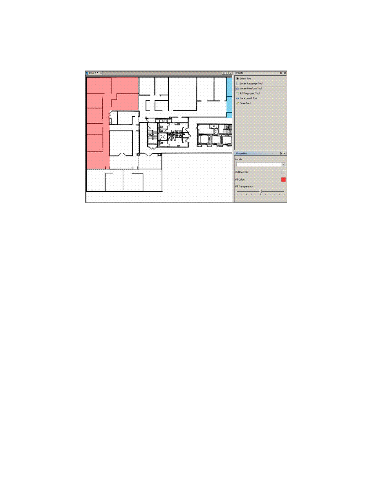
64 Nortel WLAN Location Engine 2340 Dashboard
NN47250-504 (324122-A Version 01.01)
4 The drawn area is frozen and shaded with the default fill color.
To Move Locale Labels
By default, the label for a locale is displayed at the top-center of the Locale's bounding box. Once the locale has been
drawn, you can move the label independently of the locale placement. This is helpful when the default label overlaps
with part of the background image to the point of obscuring the text.
1 Click Select Tool from the Layout Palette and then select the label.

Nortel WLAN Location Engine 2340 Dashboard 65
Nortel WLAN - Location Engine 2340 Configuration - Using Interfaces
2 You can drag the label anywhere on the layout as shown in the figure.
To deleting Locales
To delete a locale from the drawing, follow the given steps:
1 Click right mouse over the locale.
2 Select Delete from the context menu.
or
Use the Select Tool to select the locale and press the DEL key (if the locale was just drawn, it is already
selected; just press the DEL key).
Note. Even though the label may be moved, it will still be linked to the
associated locale. Deleting the label will result in deleting the locale.

66 Nortel WLAN Location Engine 2340 Dashboard
NN47250-504 (324122-A Version 01.01)
Associating Drawn Locale with Named Locale
To associate a named (configured and tracked) locale with a locale you have drawn on the layout, follow the given steps:
1 Select the name of a locale from the Locale list in the Properties panel.
2 Once you select the Locale, its name will be added to the drawing.
To shade the Locales
1 Select the Properties panel, it contains controls for setting the outline color, fill color, and fill
transparency as shown in the figure:
2 Slide the Fill Transparency control from left to right to adjust the shading from transparent to opaque.
Note. Each named locale may be associated with just one drawn locale.

Nortel WLAN Location Engine 2340 Dashboard 67
Nortel WLAN - Location Engine 2340 Configuration - Using Interfaces
3 Selecting either Outline Color or the Fill Color displays the Choose Fill Color dialog.
4 Choose the color and click OK.
Adding RF Fingerprint and Sensor icons
The physical location of each RF Fingerprint and Sensor is represented on the Layout by icons you place on the Layout
using the RF Fingerprint and Sensor tools. The icons can be placed in the spots on the layout that correspond to their
actual locale in the building. Otherwise, the device detail and Access Point association data received from the Nortel
WLAN Location Engine will not be depicted in the correct locale on the Layout.
The RF Fingerprint and Sensor tools are used in the same way, as follows:
1 Click Tool in the Palette.
2 Move the cursor to the spot on the layout, where you want the icon to appear. The cursor changes to a
hand as you move the cursor from the Tools Palette to the drawing.
3 Click left mouse to add the icon to the drawing.
4 Select the actual RF Fingerprint or Sensor from the list in the Properties panel.

68 Nortel WLAN Location Engine 2340 Dashboard
NN47250-504 (324122-A Version 01.01)
Example: The sample Floor 1 looks like this, after completing these steps with the RF Fingerprint Tool to add a single
RF Fingerprint named eng-cubes-back:
To delete icons
To delete a RF Fingerprint or Sensor from the drawing, follow the given steps:
1 Right click the mouse, over the icon.
2 Select Delete from the context menu.
or
Use Select Tool to select the icon and press the DEL key (if the RF Fingerprint was just drawn, it is
already selected; just press the DEL key).
Specifying the Layout's Scale
Indicate the layout’s scale. Any Access Point coverage views that you choose to display on the layout are rendered accurately using the data received from the Nortel WLE2340. To use the Scale Tool:
1 Measure the length or width of any physical location in the building monitored. The larger the actual
distance measured the better. For example, measure a room like a Cafeteria, Lobby, or a large area filled
with open office cubes, not an individual office.
2 Click Scale Tool in the Palette.
3 Move the cursor to the side of the drawn locale, which corresponds to the side of the actual location
where you began the physical measurement.
4 Click left mouse, and drag the cursor to the opposite side of the locale.
5 Indicate the distance and the units (feet or meters) using the Scale controls in the Properties panel.

Nortel WLAN Location Engine 2340 Dashboard 69
Nortel WLAN - Location Engine 2340 Configuration - Using Interfaces
Example: The sample Layout Floor 1 looks like this, after completing the steps with the Scale Tool:
Saving Changes to the Layout tab
When you make changes to a layout (example: adding locales), an asterisk appears in the tab, indicating that the layout
needs to be saved. Edits made to a layout can be saved in three ways:
• Right click the mouse on the layout name in the Connections panel or on the tab, and then select Save from the
context menu.
•Press CTRL-S on the layout canvas, the layout tab, or the layout name in the Connections.
• Select File>Save from the menu bar.
Viewing Live Network Activity on the Dashboard layout
In order to create views, establish a connection to a Nortel WLE2340, as described in Chapter 2, and created one or more
Layouts, as described in ‘Creating Layouts’ chapter.
A view is a real-time display of network activity displayed on a Layout. This version of the Nortel WLE2340 Dashboard
supports one type of view: Device View. At a high level, there are two steps to create and configure views:
• Use the ‘New View’ wizard to load Layout onto a View tab.
• Use the controls on the View Layers panel to configure the View.
Note. Next time you start the Nortel WLE2340 Dashboard, any layouts you
were working on will be reloaded and displayed on tabs.

70 Nortel WLAN Location Engine 2340 Dashboard
NN47250-504 (324122-A Version 01.01)
Using the New View wizard
Use the New View wizard to create a tab that contains a Layout.
Invoke the New View wizard by selecting the . (You can also invoke the wizard by highlighting the layout name in
the Server Connections panel and then selecting Add View from the either the File menu or the right mouse context
menu.)
The layout wizard has two steps:
• Enter View Details and Select View Components.
• The current step appears in bold in the Steps list.
Enter View details
1 In the Name, enter a name that describes the View, such as ‘Floor 1 Coverage View’. The name will
appear on the tab.
2 If you invoked the wizard by selecting the on the menu bar, then you need to specify the Connection
and the Layout (These are already filled in for you and grayed out if you invoked the wizard by
highlighting the Layout name in the Connections panel).
3 Enter an optional Description.
4 Click Next to advance to step 3, Select View Components.
• Device view: A live view of the distribution of devices across the locales and the Access Point to
which they are connected.
5 Click Finish. The system:
• creates a new tab containing the associated Layout
• displays the View Layers panel to the right of the tab. The View Layers panel contains the
configuration controls you use to specify the live network data you want displayed in the view.
The configuration controls available depend on which type of view is being configured, as
explained in the following sections, ‘Configuring a Device View’.

Nortel WLAN Location Engine 2340 Dashboard 71
Nortel WLAN - Location Engine 2340 Configuration - Using Interfaces
Configuring a Device View
The Device View shows a live view of the distribution of devices across the locales and the Access Point to which they
are connected. To configure a Device view, use the controls on the View Layers panel, shown here:
Note. The Device View checkbox is not used to configure the View, but to toggle the
Connection data. Enter on/off when monitoring a live Device View.
Note. If the View Controls panel does not appear to the right of the View, select ‘View
Controls’ from the Window menu. Additionally the center pane may need resizing.

72 Nortel WLAN Location Engine 2340 Dashboard
NN47250-504 (324122-A Version 01.01)
Choosing Layout Elements to display
By default, the only elements from the underlying Layout that are displayed in the view are the locales. Toggle the
checkbox to show/hide the underlying Layout's Locales, RF Fingerprints, and Sensors.
Choosing Devices to display
By default, all powered devices within range of the wireless network are displayed in the view.
To display a subset of the powered devices:
1 Select the Only Display Selected Devices.
2 Click Add to display the Add dialog.
3 Choose one of the following criteria in the Add dialog:
• Bands: 802.11A or 802.11B/G
• Channels: Specific 802.11 channels.
• Devices: Individual devices listed by label or MAC address.
• Device Types: Client, Ad Hoc, or Access Point.
• Groups: Just the devices in the specified group.
• Networks: Just the devices on the specified networks.
4 Choose either to display the device on the basis of the device is or is not part of the selected criteria.
5 Choose one or more values for the selected criteria.
Use the Any radio button to show devices that meet any of the rules, and the All radio button to display only devices
meeting all of the rules.
Showing association lines
By default, a line connects each device icon with the Access Point with which it is associated. De-select the checkbox to
remove these lines from the view.
Highlighting devices
Use the Highlight feature to emphasize a subset of devices, but still showing the broader set of devices on the dashboard.
You can emphasize selected devices based on the same criteria used to choose devices to display.
By Default, highlighting categories are not created. To highlight the devices in a specific network, follow the given
steps:

Nortel WLAN Location Engine 2340 Dashboard 73
Nortel WLAN - Location Engine 2340 Configuration - Using Interfaces
1 Select Add from the Highlight Selected Devices dropdown. The Add Objects to Display dialog
appears. Select Networks from the dropdown and make sure the is selected. Choose the is not to
highlight everything except the chosen network.
2 Select the desired network (use the shift key to multi-select) and click OK.
3 The device you select will be emphasized and dashboard will fade rest of the devices.

74 Nortel WLAN Location Engine 2340 Dashboard
NN47250-504 (324122-A Version 01.01)
Example: Device View
Access Points, Client devices, and Adhoc devices in the view are displayed in their actual location. For example:
Mouse over a locale to display the number of devices in that locale. To display the Device List for a locale, right mouse
click over the locale and select ‘View Devices in <Locale>’ from the context menu.
Saving changes to the View tab
When you make changes to view, an asterisk appears in the tab. It indicates that the layout needs to be saved. Edits made
to a layout can be saved in three ways:
1 Right-mouse click on the view name in the Connections panel or on the tab, and then select Save.
2 CTRL-S on the layout canvas, the layout tab, or the layout name in the Server connections.
3 Select File>Save from the menu bar.
Note. The next time you start the Nortel WLE2340 Dashboard, any layouts you were
working will be reloaded and displayed on tabs.


Nortel WLAN - Location Engine 2340 Configuration - Using
Interfaces
Nortel WLAN Location Engine
Release 6.0
Document Number: NN47250-504
Document Status: Standard
Document Version: 01.01
Part Code: 324122-A
Release Date: October 2007
Copyright © Nortel Networks Limited 2007 All Rights Reserved
The information in this document is subject to change without notice. The statements, configurations,
technical data, and recommendations in this document are believed to be accurate and reliable, but are
presented without express or implied warranty. Users must take full responsibility for their applications
of any products specified in this document. The information in this document is proprietary to Nortel Networks.
*.Nortel, Nortel Networks, the Nortel logo, and the Globemark are trademarks of Nortel Networks
*Microsoft, MS, MS-DOS, Windows, and Windows NT are registered trademarks of Microsoft Corporation.
All other trademarks and registered trademarks are the property of their respective owners.
To provide feedback, or to report a problem in this document, go to www.nortel.com/documentfeedback.
 Loading...