

2GIG-SMKT2-345
L
I
S
T
D
WIRELESS PHOTOELECTRIC
SMOKE ALARM
Installation
Instructions
R
I
CM
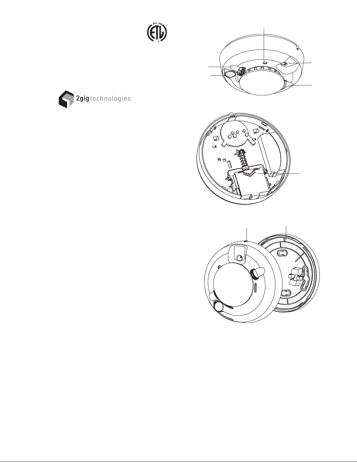
Temperature
Sensor
Test/Silence
button
LED
Sounder vent
Temperature
sensor
388 West Center Street
Orem, UT 84057
Technical Support 866-670-1591
www.2gig.com
DESCRIPTION
The 2GIG-SMKT2-345 is a photoelectric smoke alarm with a built-in transmitter
designed for use with the 2GIG-CNTRL-345 security system. When smoke is
detected, the alarm sounds a loud local alarm. Twenty seconds after the local
alarm sounds, the built-in transmitter sends a digitally coded wireless signal to
the Control Panel. The wireless signal will be repeated every 20 seconds as
long as smoke is still present.
In addition to the photoelectric detector, the unit contains an integrated fi xed
135° temperature and rate-of-rise heat sensor that will send an alarm signal
based on temperature detected.
BUILT-IN WIRELESS TRANSMITTER
The smoke alarm can send three different wireless signals to the alarm Control
Panel: alarm, low battery, and status.
Every hour, the smoke alarm sends a status transmission to the Control Panel.
The hourly signal updates the Control Panel with the smoke alarm’s condition.
By monitoring status transmissions, the Control Panel can determine that the
smoke alarm is still operational in the installation and if it has a low battery.
The Control Panel must be programmed to the transmitter’s serial
number before system testing and operation. Refer to the Control Panel’s
instructions for details on programming.
INSTALLATION
1. Slide the battery compartment cover away from the unit to unsnap it and
lift it off. See Figure 2.
2. Observing proper polarity, insert the two 3V lithium batteries supplied into
the alarm battery compartment and replace the battery cover.
3. Remove the red plastic dust cover from the unit.
4. Refer to Page 3 for selecting a proper location for the smoke alarm.
5. Using the two screws and anchors provided, mount the base.
6. Attach the unit to the base as follows:
• Line up the raised alignment tab on the lip of the unit with the alignment
arrow on the base. See Figure 3.
• Insert the unit into the base and turn clockwise approximately 15
degrees. It should snap fi rmly into place.
• IMPORTANT: The unit cannot be attached to the base if no batteries
are installed.
PROGRAM SMOKE ALARM INTO THE CONTROL PANEL
Before testing the smoke alarm, the internal wireless transmitter must be
programmed into the Control Panel.
1. Refer to the Control Panel’s instructions to prepare the receiver to accept
the smoke alarm’s serial number.
2. Press the smoke alarm’s TEST/SILENCE button for 4 seconds. The
smoke alarm will perform a sounder test, a sensitivity test, and send a
test signal to the Control Panel.
3. Verify that the signal was received by the Control Panel and that the
sensor was entered into the system.
4. Exit Control Panel programming before testing the smoke alarm.
Figure 1. Smoke Alarm Features
Battery
compartment
Figure 2. Battery Compartment
Alignment tab
Alignment arrow
Figure 3. Smoke Alarm-to-Base Alignment
SMOKE TEST
Units should be tested in place annually using one of the following methods:
A. Use Smoke! in a can® and follow directions on the can.
B. Hold a smoldering punk or cotton wick close to the unit and gently direct
the smoke into the smoke entry openings for 20 seconds or until an alarm
is indicated.
The smoke alarm LED should stay on and the sounder should emit a temporal
three pattern, and an alarm should be indicated at the Control Panel. Disarm
the system to reset the Control Panel alarm. Be sure to extinguish the
smoke source after testing!
SILENCE THE ALARM
Press the TEST/SILENCE button to silence the sounder during an alarm. After
a few minutes, the sounder and alarm resume if smoke is still present.
1
SENSITIVITY TEST
1. Press and hold the TEST/SILENCE button for 4 seconds. Once the test
starts, the smoke alarm LED fl ashes 1 to 9 times.
2. Count the number of LED fl ashes and use the following table to determine
if any action is necessary.
FLASHES INDICATION ACTION
0-1
2-3
4-7
Unserviceable
hardware fault
Unit is becoming
insensitive
Unit is within normal
sensitivity range
Reset and rerun sensitivity test. If
the error persists, replace the unit.
Clean and reset the unit. Rerun
sensitivity test. If the error persists,
replace the unit.
No action required
Verify that the optical chamber is
8-9
Unit is becoming too
sensitive
snapped down securely. Clean
the unit and replace the optical
chamber.
After the LED fl ashes, if the sensitivity is within limits and all other tests pass,
the unit goes into alarm and resets after 7 seconds. If the sensitivity is not
within limits, or an unserviceable hardware fault has been detected, the unit
LED extinguishes until the unit is serviced.
LED FUNCTIONS
Flashing — Flashes every 9 seconds to indicate normal operation.
On — Detects smoke
Off — Trouble or maintenance is required.
WHEN TO REPLACE THE BATTERIES
When the batteries are low, the unit extinguishes its LED and chirps every 45
seconds until the batteries are replaced. The low battery trouble chirps can be
silenced for 24 hours by pressing the TEST/SILENCE button. Battery life is a
minimum of one year, and varies depending on how often the unit is tested.
REPLACING THE BATTERIES
Use only 3V lithium batteries listed on the battery compartment cover.
1. Remove the unit from the mounting base, grasp the unit and turn it
counterclockwise approximately 15 degrees.
2. Slide the battery compartment cover away from the smoke alarm to
unsnap it and lift it off. See Figure 2.
3. Remove the batteries and dispose of them properly.
4. Observing correct polarity, insert two new 3V lithium batteries into the
battery compartment and replace the cover.
5. Reattach the unit to the mounting base. See Installation, Step 6.
6. Test the system.
CLEANING
Clean the cover with a dry or damp (water) cloth as needed to keep it free
from dust and dirt.
When necessary, clean the interior and replace the optical chamber (part
number ??????) as follows:
1. To remove the unit from the mounting base, grasp the unit and turn it
counterclockwise approximately 15 degrees.
2. Remove the batteries.
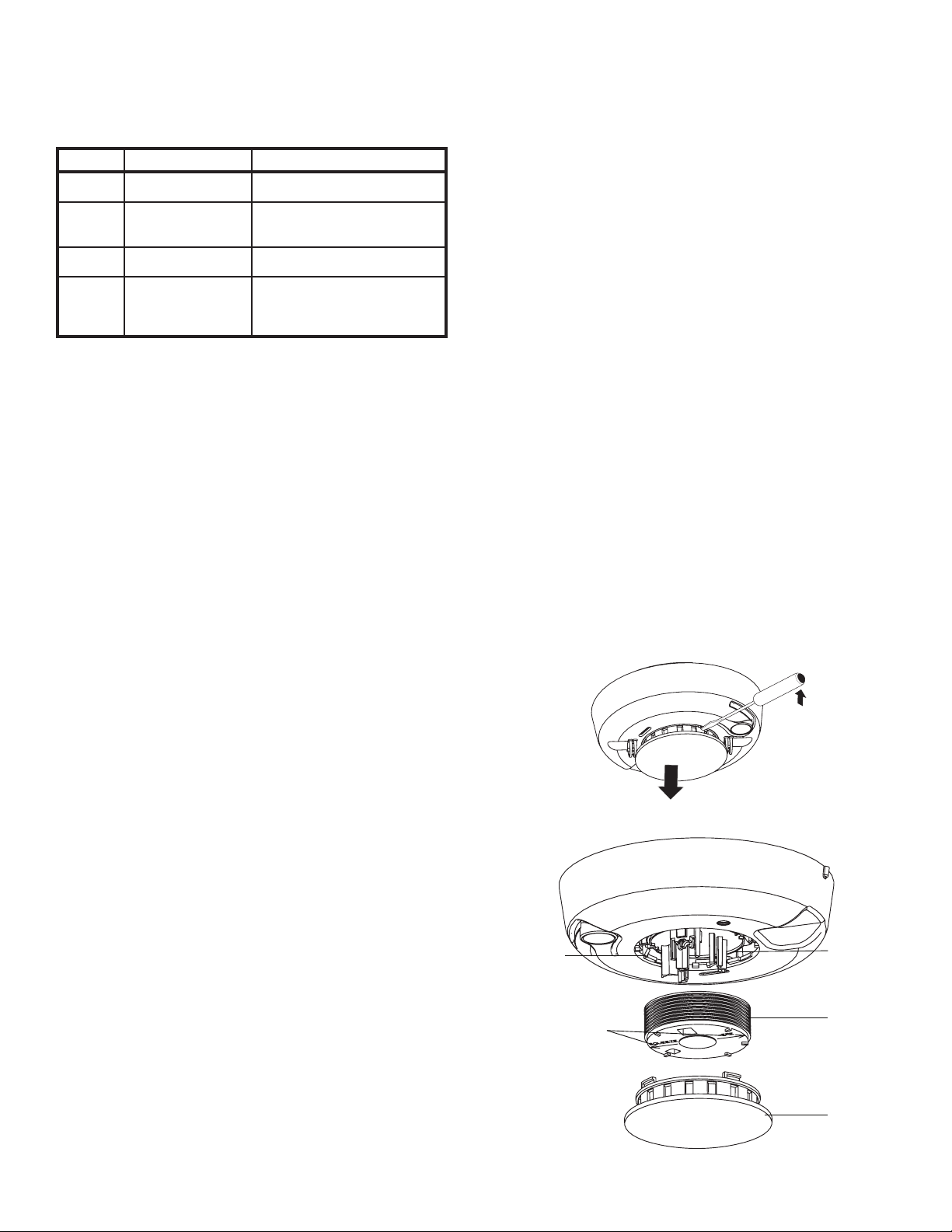
3. Slide a fl at-blade screwdriver in the slot on the alarm cap and gently push
the handle down to pry the alarm cap up and off. See Figure 4.
4. Squeeze the optical chamber where indicated and pull it up and away
from the optical base and discard. See Figure 5.
5. Blow out or use a soft-bristled brush to remove all dust and dirt from the
optical base.
6. Line the new smoke chamber up with the optical base by lining up the
arrows on the optical chamber to the latches on the optical base. Ensure
that the LED cavity in the optical chamber is above the LED and snap the
optical chamber down into place.
7. To replace the alarm cap as follows:
• Line the alarm cap up with the unit.
• Insert the alarm cap into the unit and turn clockwise approximately 15
degrees. It should snap fi rmly into place.
2
8. Observing proper polarity, replace the batteries and the battery
compartment cover.
9. Reattach the unit to its mounting base. See Installation, Step 6.
10. Test the unit sensitivity.
MAINTENANCE
The units are designed for easy fi eld service and maintenance. When installed
and used properly, they require minimal maintenance.
The unit should be tested weekly.
When a unit requires maintenance, it extinguishes its LED and stops sending
supervisory signals to the alarm Control Panel.
If the Control Panel indicates supervisory trouble for the smoke alarm, perform
the sensitivity test and follow the recommended actions.
SPECIFICATIONS
Voltage 3VDC
Typical average standby current 35µA
Typical test current 2mA
Typical alarm current 70mA
Battery type 3V lithium, Duracell® 123, Panasonic
CR123A, Sanyo® 123A
Low battery threshold 2.70V causes low battery signal
Sounder 85dBa at 10’ temporal pattern
Low battery beep rate 1 every 45 sec.
Sensitivity 2.2% ± 1.3% / ft.
Operating temperature 40°-100°F (4.4°-37.8°C)
Operating humidity range 0-95% non-condensing
Color White
Alarm dimensions 5.6” x 2.4” (14.2 cm x 6.1cm)
Base dimensions 5.4” x 0.46” (13.7 cm x 1.17cm)
Drift compensation adjustment 0.5% / ft. max.
Heat detector specifications
Rate-of-rise 15°F/min>105°F
(8.3°C/min>40.6°C
Fixed 135°F ± 5°F (57.2°C ± 2.8°C)
Listings ETL, UL217, CSFM
Figure 4. Removing the Smoke Alarm Cap
Smoke
chamber
latch
Alignment
arrows
Optical base
Optical
chamber
Alarm Cap
Figure 5. Smoke Alarm Parts
®

SELECTING A LOCATION
Selecting a suitable location is critical to the operation of smoke alarms. This
equipment should be installed in accordance with National Fire Protection
Association’s (NFPA) Standard 72 (see Figure 6).
A-11-8.3a Where to Locate the Required Smoke Alarms in Existing
Construction.
The major threat from fi re in a family living unit occurs at night when everyone
is asleep. The principal threat to persons in sleeping areas comes from fi res in
the remainder of the unit. Therefore, a smoke alarm(s) is best located between
the bedroom areas and the rest of the unit. In units with only one bedroom area
on one fl oor, the smoke alarm(s) should be located as shown in Figure 6A.
In family living units with more than one bedroom area or with more than one
fl oor, more than one smoke alarm is required, as shown in Figure 6B.
In addition to smoke alarms outside of the sleeping areas, the installation of
a smoke alarm on each additional story of the family living unit, including the
basement, is required. These installations are shown in Figure 6C. The living
area smoke alarm should be installed in the living room or near the stairway
to the upper level, or in both locations. The basement smoke alarm should be
installed in close proximity to the stairway leading to the fl oor above. Where
installed on an open-joisted ceiling, the alarm should be placed on the bottom
of the joists. The alarm should be positioned relative to the stairway to intercept
smoke coming from a fi re in the basement before smoke enters the stairway.
Where to Locate the Required Smoke Alarms in New Construction.
All of the smoke alarms specifi ed for existing construction are required and, in
addition, a smoke alarm is required in each bedroom.
Are More Smoke Alarms Desirable?
The required number of smoke alarms might not provide reliable early warning
protection for those areas separated by a door from the areas protected by the
required smoke alarms. For this reason, it is recommended that the householder
consider the use of additional smoke alarms for those areas for increased
protection. The additional areas include the basement, bedrooms, dining
room, furnace room, utility room, and hallways not protected by the required
smoke alarms. The installation of smoke alarms in kitchens, attics (fi nished
or unfi nished), or garages is not normally recommended, as these locations
occasionally experience conditions that can result in improper operation.
Since regulations pertaining to smoke alarm/detector installation vary from
state to state, contact the authority having jurisdiction (AHJ). Where public
safety is primary, the AHJ may be fedral, state, local, or other regional
department or individual such as a fi re chief, fi re marshal, chief of a fi re
prevention bureau, labor or health department, building offi cial, electrical
inspector, or others having statutory authority. For insurance purposes, an
insurance inspection department, rating bureau, or other insurance company
representative may be the AHJ. In some cases, the property owner or their
designated agent assumes the role of the AHJ. At government installations,
the commanding offi cer or department offi cial may be the AHJ.
In addition to NFPA 72, use the following location guidelines to optimize
performance and reduce the chance of false alarms from the alarm:
• Locate ceiling-mounted smoke alarms in he center of a room or hallway
at least 4 inches (10cm) from any walls or partitions.
• Locate wall-mounted smoke alarms so the top of the alarm is 4 to 12
inches (10 to 31cm) below the ceiling.
• Locate in a suitable environment as follows:
• Temperature between 40°F (4.4°C) and 100°F (37.8°C)
• Humidity between 0 and 95% non-condensing
• Locate away from air conditioners, heating registers, and any other
ventilation source that may interfere with smoke entering the alarm.
• Mount smoke alarms on a fi rm permanent surface.
• Locate away from large metallic objects to reduce shielding of the
wireless transmitter’s signal.
Smoke alarms are not to be used with detector guards unless the
combination has been evaluated and found suitable for that purpose.
A
B
IMPORTANT: Regulations pertaining to
smoke alarm installations vary from
state to state. For more information,
contact your local fire department or
local authority having jurisdiction.
Figure 6. Smoke Alarm Placement
Indicates additional smoke alarms
required for new construction
C
3

WARNING! LIMITATIONS OF SMOKE ALARMS
Wireless smoke alarms are very reliable, but may not work under all conditions.
No fi re alarm provides total protection of life or property. Smoke alarms are not
a substitute for life insurance.
Smoke alarms require a source of power to work. This smoke alarm will
not operate and the alarm will not sound if batteries are dead or not installed
properly.
Smoke alarms may not be heard. A sound sleeper or someone who has
taken drugs or alcohol may not awaken if the alarm is installed outside a
bedroom. Closed or partially closed doors and distance can block sound. This
alarm is not designed for the hearing impaired.
Smoke alarms may not always activate and provide warning early
enough. Smoke alarms only activate when enough smoke reaches the alarm.
If a fi re starts in a chimney, wall, roof, on the other side of closed doors, or on
a different level of the property, enough smoke may not reach the alarm for it
to alarm.
Smoke alarms are a signifi cant help in reducing loss, injury and even death.
However, no matter how good a detection device is, nothing works perfectly
under every circumstance and we must warn you that you cannot expect a
smoke alarm to ensure that you will never suffer any damage or injury.
Current studies have shown smoke alarms may not awaken all sleeping
individuals. It is the responsibility of individuals in the household that are
capable of assisting others to provide assistance to those who may not be
awakened by the alarm sound, or to those who may be incapable of safely
evacuating the area unassisted.
FIRE PREVENTION AND ESCAPE
The purpose of an early warning smoke alarm is to detect the presence of fi re
in its early stages and sound an alarm giving the occupants time to exit the
premises safely.
AVOID FIRE HAZARDS
No detection device can protect life in all situations. Therefore, safeguards
should be taken to avoid potentially dangerous situations as follows:
• Do not smoke in bed.
• Do not leave children home alone.
• Never clean with fl ammable liquids such as gasoline.
• Properly store materials. Use general good housekeeping techniques
to keep your home neat and tidy. A cluttered basement, attic, or other
storage area is an open invitation to fi re.
• Use combustible materials and electrical appliances carefully and only
for their intended uses. Do not overload electrical outlets
• Do not store explosive and/or fast burning materials in your home.
• Even after proper precautions have been taken, fi res can start. Be
prepared.
IN CASE OF FIRE
In the event of a fi re:
• Leave immediately. Don’t stop to pack or search for valuables.
• In heavy smoke, hold your breath and stay low, crawl if necessary. The
clearest air is usually near the fl oor.
• If you have to go through a closed door, carefully feel the door and door
knob to see if undue heat is present. If they seem cool, brace your foot
against the bottom of the door with your hip against the door and one
hand against the top edge. Open it slightly. If a rush of hot air is felt, slam
the door quickly and latch it. Unvented fi re tends to build up considerable
pressure. Be sure all members of the household realize and understand
this danger.
• Use your neighbor’s phone or a street fi re alarm box to call the fi re
department. The job of extinguishing the fi re should be left to the
professionals.
BE PREPARED
Practice the following steps to prepare you and your family in the event of a fi re:
• Perform fi re drills regularly. Use them to assure recognition of an alarm
signal.
• Draw a fl oor plan and show two exits from each room. It is important
that children be instructed carefully, because they tend to hide in times
of crisis.
• Establish one meeting place outside the home. Insist that everyone
meet there during an alarm. This will eliminate the tragedy of someone
reentering the house for a missing member who is actually safe.
• If you have children and/or physically challenged people residing in your
household, use window decals to help emergency personnel identify the
sleeping quarters of these individuals.
WARNING
Smoke alarms CANNOT provide warnings for fi res resulting from
explosions, smoking in bed or other furniture, ignition of fl ammable
liquids, vapors and gases, children playing with matches or lighters.
LIMITED WARRANTY
This 2GIG Technologies product is warranted against defects in material
and workmanship for two (2) years. This warranty extends only to
wholesale customers who buy direct from 2GIG Technologies or through
2GIG Technologies’ normal distribution channels. 2GIG Technologies does
not warrant this product to consumers. Consumers should inquire from
their selling dealer as to the nature of the dealer’s warranty, if any. There
are no obligations or liabilities on the part of 2GIG Technologies for
consequential damages arising out of or in connection with use or
performance of this product or other indirect damages with respect
to loss of property, revenue, or profi t, or cost of removal, installation,
or reinstallation. All implied warranties, including implied warranties for
merchantability and implied warranties for fi tness, are valid only until the
warranty expires. This 2GIG Technologies Warranty is in lieu of all other
warranties express or implied.
SERVICING INFORMATION:
All products returned for warranty service require a Return Product
Authorization Number (RPA#). Contact 2GIG Technologies at 1-866-670-1591
for an RPA# and other important details.
For additional warranty and compliance information, visit our Web site at:
www.2gig.com
IMPORTANT!!!
Radio controls provide a reliable communications link and fi ll an important
need in portable wireless signaling. However, there are some limitations which
must be observed.
• For U.S. installations only: The radios are required to comply with FCC
Rules and Regulations as Part 15 devices. As such, they have limited
transmitter power and therefore limited range.
• A receiver cannot respond to more than one transmitted signal at a time
and may be blocked by radio signals that occur on or near their operating
frequencies, regardless of code settings.
• Changes or modifi cations to the device may void FCC compliance.
• Infrequently used radio links should be tested regularly to protect against
undetected interference or fault.
• A general knowledge of radio and its vagaries should be gained prior
to acting as a wholesale distributor or dealer, and these facts should be
communicated to the ultimate users.
FCC COMPLIANCE
This device complies with Part 15 of the FCC Rules. Operation is subject to the
following two conditions: (1) This device may not cause harmful interference.
(2) This device must accept any interference received, including interference
that may cause undesired operation.
Copyright © 2010 230723 X1
4
 Loading...