

Page 1

8” Interactive Touch Panel
User Interface
Quick Install Guide
ITP-8
Page 2

QUICK INSTALL GUIDE
Thank you for including the ITP-8 as part of the user inter face strategy for
your customer. The ITP-8 has been designed to provide years of trouble free
operation when wired and installed properly. The ITP-8 has been designed
for installation in low humidity indoor environments and should never be
installed outdoors or in high humidity areas.
Included in the box
• 1ea ITP-8 touch panel
• 1ea ITP-8 mounting bracket
• 1ea panel removal key
• 4ea mounting screws
• 1ea DC power connector
To install the ITP-8 you will need a standard 2-gang US junction box
or low voltage bracket (not included).
SPECIFICATIONS:
Dimensions
Overall: 8w x 5.5h (in)
20.33w x 13.98h (cm)
Mounting Depth: 1 (in) / 2.54 (cm)
Audio
Microphone: Dual Digital MEMS
Microphone-Array
Speake r: Stereo Micro Speakers (2)
Video
Camera: 5 MP CMOS sensor
Display: 8" / 1920 x 1200
2
Network
10/10 0 Ether ne t
802.11 B / G / N W i F i
Connections
LAN/PoE RJ45
Power 2-pin Phoenix
USB Type A
Power Requirements
Direct – 12V 1A
PoE – IEEE 802.3at,
13W maximum draw
(@48V 270mA max)
Page 3

ITP-8
IMPORTANT SAFETY INSTRUCTIONS:
1. Read these instructions.
2. Keep these instructions.
3. Heed a ll warni ngs.
4. Follow all instructions.
5. Do not us e this app aratus ne ar water.
6. Clea n only wit h dry clot h.
7. Install in accordance with the manufacturer’s instructions.
8. Do not in stall ne ar any heat s ources s uch as radi ators, hea t registe rs,
stoves or other apparatus (including amplifiers) that produce heat.
9. Only use attachments/accessories specified by the manufacturer.
10. Unplug th is appar atus duri ng lightn ing storms o r when unused for lo ng perio ds of time.
11. Refer al l servi cing to qualified se rvic e person nel. Ser vicing i s require d when the a pparatu s has
been da maged in an y way such as p ower-supply c ord or plug is damag ed, liqui d has been s pilled
or objec ts have fall en into the ap paratus, t he appar atus has be en expos ed to rain or mo isture,
does not o perate nor mally, or has b een drop ped.
FCC AND IC INFORMATION:
This Cla ss B digital appa ratus complies w ith Part 15 of the FCC rule s and with Canadi an ICES-003 and R SS-247.
Opera tion is su bject to th e followi ng two con dition s:
1. This dev ice may not c ause inter ference and
2. This devic e must accept any i nterferenc e, including inte rference tha t may cause unde sired operatio n of the device.
NOTE:
This equ ipment h as been tes ted and fou nd to compl y with the li mits for a Cla ss B digit al devic e,
pursua nt to Part 15 of the Fe deral Co mmunic ations Co mmissi on (FCC) rul es. Thes e limits are
designed to provide reasonable protection against harmful interference in a residential installation.
This equ ipment g enerate s, uses and c an radiate radio fre quency e nergy an d, if not inst alled an d used in
accordance with the instructions, may cause harmful interference to radio communications.
However, there i s no guara ntee that int erfere nce will n ot occur in a p artic ular inst allatio n. If this equ ipment
does cau se harmf ul inter ferenc e to radio or tel evisio n receptio n, which can be deter mined by tu rning the
equipm ent off an d on, the use r is encou raged to tr y to correct the inter ference by one or mo re of the
following measures:
• Reorie nt or relocate the rec eiving a ntenna.
• Increa se the sepa ration be tween th e equipme nt and receiver.
• Connec t the equi pment into a n outlet on a c ircuit di ffere nt from that to w hich the re ceiver is conne cted.
• Consult the dealer or an experienced radio/TV technician for help.
Le présen t appare il est confo rme aux CNR d ’Industr ie Canada a pplica bles aux a pparei ls radio exe mpts
de licen ce. L’exploitation es t autorisé e aux deux conditi ons suivan tes : (1) l’appareil ne d oit pas pro duire
de brouillage, et (2) l’utilisateur de l’appareil doit accepter tout brouillage radioélectrique subi, même si le
brouillage est susceptible d’en compromettre le fonctionnement.
FCC AND IC REGISTRATIONS:
FCC ID: EF400182 IC ID: 1078A-00182
CAN ICES- 3B / NMB-3B
3
Page 4

QUICK INSTALL GUIDE
WARNING:
Change s or modifi cations to th is unit not e xpress ly approve d by the par ty resp onsible
for compliance could void the user’s authority to operate the equipment.
FCC AND IC RADIATION EXPOSURE STATEMENT:
This equipment complies with FCC radiation exposure limits set forth for an uncontrolled
environ ment and m eets the exe mption fro m the routi ne evaluat ion limit s in sectio n 2.5 of RSS 102.
1. This Transm itter mus t not be co-l ocated or o peratin g in conju nction wi th any other a ntenna
or transmitter.
2. This equipment complies with FCC RF radiation exposure limits set forth for an uncontrolled
environment.
FCC/IC RF RADIATION EXPOSURE STATEMENT:
Cauti on:
This Transm itter mus t be instal led to provi de separ ation dis tance of at l east 20cm f rom all persons.
FCC / IC RF Radiation Déclaration d’exposition
Atten tion:
Cet émet teur doit être inst allé pour fourn ir une distance d e séparation d’au mo ins 20 cm de toute pers onne.
WARNING:
The devi ce meets th e exemptio n from the rou tine eval uation lim its in section 2.5 of RSS 102,
and users can obtain Canadian information on RF exposure and compliance from the Canadian
Representative Product Solutions Group at Tel: (519) 763-4538.
4
Page 5
ITP-8
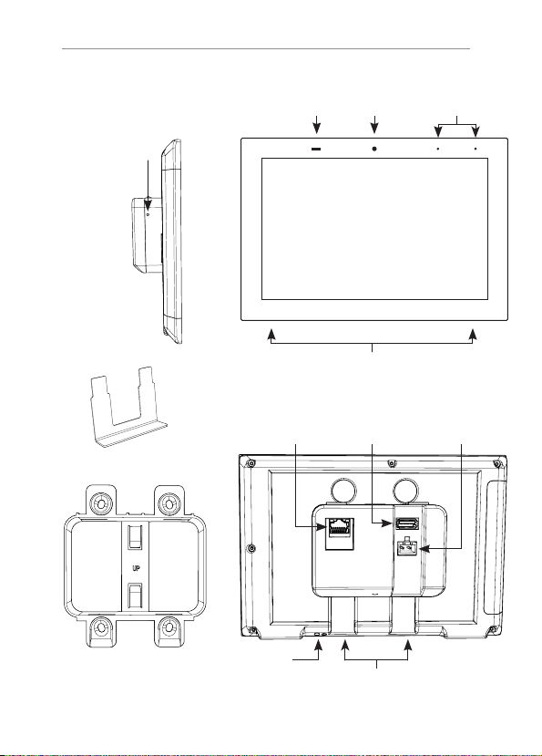
ITP-8 OVERVIEW
Recessed Reset
Switch
Release Key
Proximit y / Light
Sensors
LA N + Power over
Ethernet
MicrophonesCamera
Speakers
DC Power InputUSB
Mounting Bracket
Power
Key Channels
5
Page 6
QUICK INSTALL GUIDE
PLANNING THE INSTALLATION
The ITP-8 is designed to wall mount in either Por trait or Landscape
orientation. Ensure there is adequate wall space for the ITP-8 and that the
surface is relatively smooth.
The ITP-8 requires a minimum mounting depth of 1¾” (4.5 cm) from the
front surface plus room for wire. Ensure that adequate depth is available.
Power may be supplied by Power Over Ethernet (PoE) or by a 12V DC
power supply (not included). PoE must meet the IEEE 802.3af standard.
Direct power via a 12V DC external power supply requires a minimum
current output of 1A.
The ITP-8 connects to the local network via Ethernet or Wi-Fi.
When using Wi-Fi you must ensure that there is adequate Wi-Fi coverage
at the mounting location.
1
Installing the ITP-8
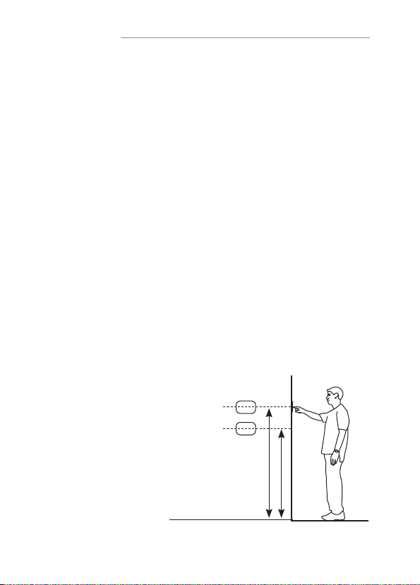
a. Mounting Height
Depending on how tall
your homeowner is, it is
recommended to locate the
center of the panel between
57”- 65” (145 cm -165 cm)
above the finished floor.
6
165 cm / 65”
145 cm / 57”
Page 7
b. Mounting Bracket
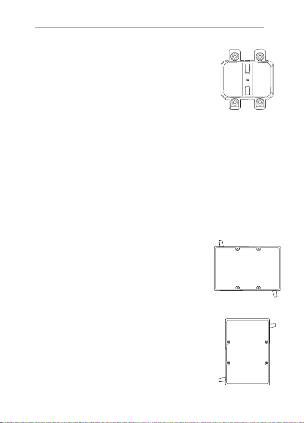
The ITP-8 has been designed to mount to a
US standard 2 gang box or low voltage bracket.
The ITP-8 bracket mounts to the standard 2 gang
box and the ITP-8 snaps into the ITP-8 bracket.
ITP-8
Mounting Bracket
New Con struct ion Box Retrofit Box New Construction
Low Voltage Bracket
c. Landscape Mounting
Install the 2 gang box or bracket in it’s normal
orientation – with mounting screw holes at the
top and bottom.
d. Portrait Mounting
Install the 2 gang box or bracket rotated 90° with the mounting screw holes on the left and
right sides.
Retrofit Low
Voltage Bracket
2 Gang Box
2 Gang Box
7
Page 8
QUICK INSTALL GUIDE
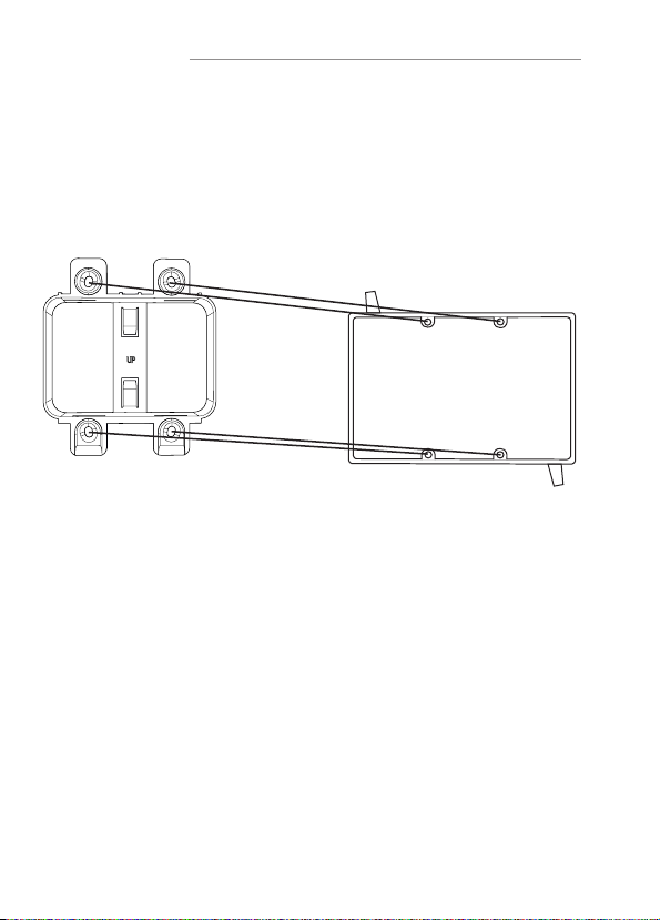
e. Installing the ITP-8 Bracket
The ITP-8 includes a mounting bracket that must be used. Using the
included screws, mount the bracket to a standard 2 gang electrical box
or low voltage bracket and verify that the bracket is level before tightening
the screws.
2 Gang Box
f. Connecting the ITP-8 to Power
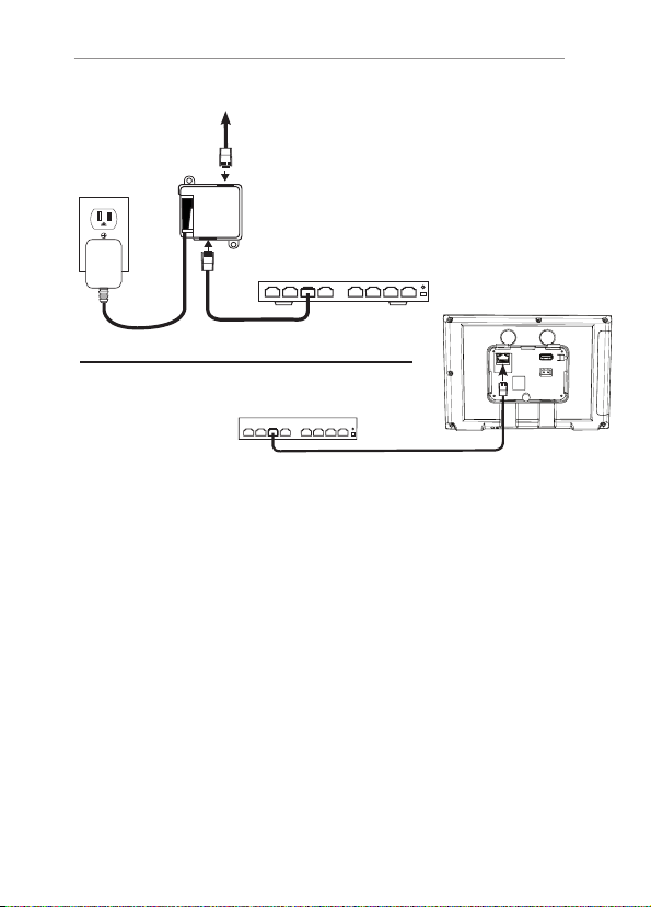
The ITP-8 is designed to be powered over the Ethernet conne ction (PoE)
or by connecting a 12V DC power supply (not included), but not both.
If both the PoE a nd a 12V DC power supply are connected the ITP-8 will
draw power from the 12V DC source.
PoE Connection
PoE connection re quires that IEEE 802.3af standard (13W maximum draw
@48 V DC @270 mA) is met. Use a network switch or PoE injector that meets
this standard.
Connect the ITP-8 using a standard T568A or T568B Ethernet cable from
the network switch to the LAN/PoE jack. If you have terminated your own
CAT 5e/6/7 cable use a tester to ensure that both ends have been properly
terminated.
8
Page 9
ITP-8
To IT P-8
PoE Injector
Network Switch
PoE Network Switch
12V DC Power Supply
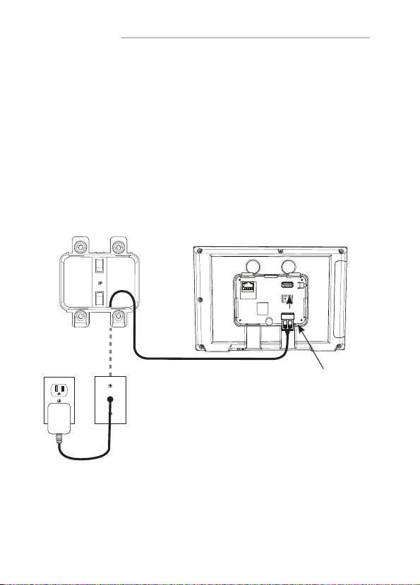
By using a 12V DC power supply (not included) to power the ITP-8 you can
provide power locally or remotely. If powering locally, be sure to run the wire
through the wall in accordance with local building and electrical codes.
If powering remotely, be sure to use wire of adequate gauge for the length
of the run.
Verify the polarity of your power supply prior to termination and ensure the
power supply is not connected to a power source.
Strip approx. ¼” of insulation from the wire, and observing the correct
polarity, terminate the wire into the supplied connector and tighten firmly.
Be sure to twist the wires before inser ting so that no strands escape the
connector. Inspect the termination to verify that the wire is securely retained
by the connector and no strands have escaped the barrier.
Plug the connector into the ITP-8.
9
Page 10
QUICK INSTALL GUIDE
g. Connecting Ethernet
When not using PoE, and you have a physical network connection available
it is recommended that you connect the ITP-8 directly to the network switch.
Using a T568A or T568B network cable, connect to the LAN/PoE jack.
If you have terminated your own CAT 5e/6/7 cable use a tester to ensure that
both ends have been properly terminated.
Mounting Bracket
Line in wall
Back of I TP-8
Phoenix Typ e
Connector
10
Page 11
ITP-8
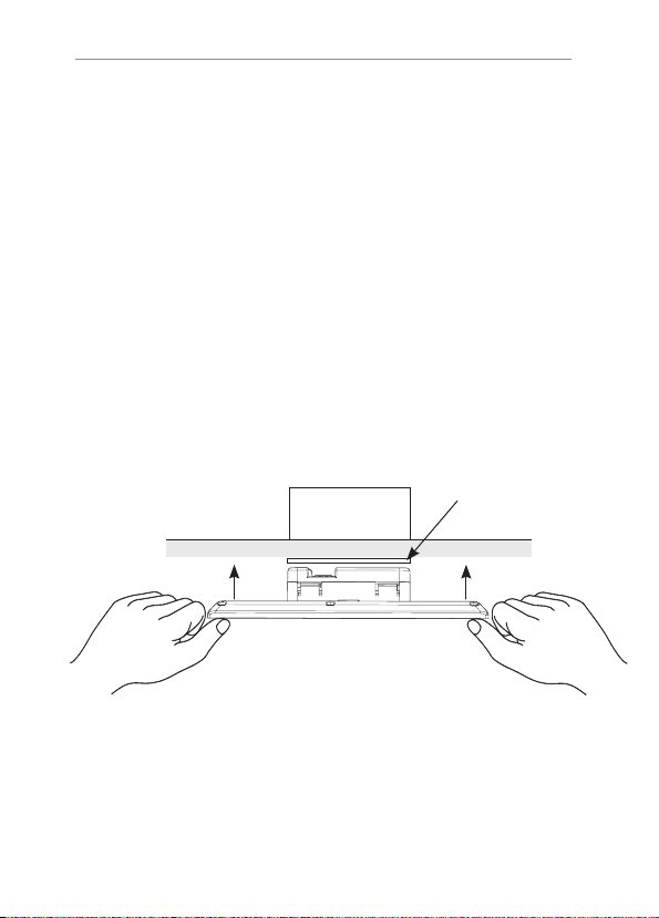
h. Mounting the ITP-8
The ITP-8 is held into the mounting bracket by with tabs on the rear of the
panel.
Orient the panel with the camera, microphones, and sensors button at the
top for landscape mounting, or the right side for portrait mounting.
To complete the installation simply grasp the ITP-8 on the edge s and press
firmly on to the bracket until it is settled.
CAUTION: DO NOT PRESS DIRECTLY ON THE SCREEN
When installing on to the mounting bracket. Press only on the frame and
take care not to use too much force.
Mounting BracketTop of 2 Gang Bo x
Dry Wall
ITP-8 Frame
11
Page 12
QUICK INSTALL GUIDE
2
Powering up the ITP-8
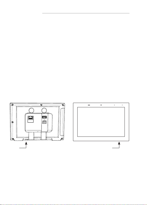
Apply power (12V DC or PoE) and wait for the unit to boot up.
If connected to a wired Ethernet switch the ITP-8 will acquire a network
address via DHCP and automatically connect to the system.
If the ITP-8 does not detect a wired Ethernet connection and the WiFi radio
has not been configured, you will need to set up the wireless connection.
In the setup menu select the wireless connection and follow the on screen
instructions to set up the wireless connection. For wireless setup, see
Section 3 - Startup Settings.
Rear View Front View
12
Power
Power
Page 13

ITP-8
3
Startup Settings
After applying power to the ITP-8, un-check the Auto Star t check-box then
tap the Configure button.
From here, you will see the Star tup options:
a. Configure WiFi
To use WiFi, check the Enable WiFi box, select the SSID and enter the
password.
b. Orientation Setup
Configure whether the panel will be installed in por trait or landscape mode.
Note: The ITP-8 is optimized for use in landscape mode.
c. Camera Enable / Disable
The ITP-8 camera can be enable or disabled. When disabled, the panel
will not transmit v ideo but can still be used for face recognition.
d. Proximity Sensor Sensitivity
Adjust the sensitivity of the proximity sensor for waking up the panel.
e. Controller Binding
If more than one controller is used on the same network, specif y which
controller the ITP-8 should be assigned to.
13
Page 14
QUICK INSTALL GUIDE
4
Reset
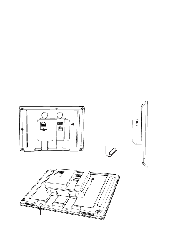
The recessed RESET button has two functions.
Press and hold the button for 3 seconds to reset the panel settings.
With the unit powered off, press and hold the but ton then power the unit
on to reset to the default factory configuration.
CAUTION :
Neit her of t hes e acti ons ca n be reve rse d.
Recessed
Reset Switch
Recessed
Reset Switch
LA N + Power
over Ethernet
Power
Button
Paper Clip
Reset Button
Factor y Default Sett ing
14
Page 15
5
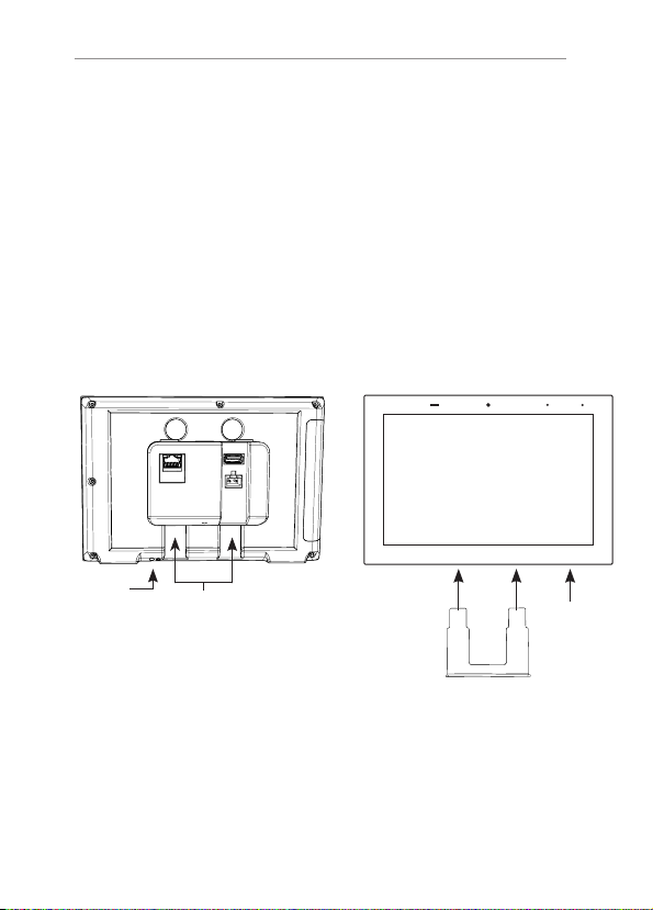
Removing the ITP-8
Slide the removal key behind the panel taking care to insert in the key
channels on the re ar of the panel and avoid making contact with the wall.
Press up on the removal key to release the locking tabs. Once unlocked,
pull the bottom of the panel away from the wall, then pull out.
Rear View Front View
ITP-8
Power
Key Channels
Power
15
Page 16

LIMITED WARRANTY
Nortek Security & Control ( ‘NS C’ ) warrants the ITP-8 to be free from defects in materials
and workmanship for the period of t wo years (2 years) from the date of purchase. If within the
applicable warranty period above purchaser discovers that such item was not as warranted
above and promptly notifies ‘N SC’ in writing, ‘NSC’ shall repair or replace the item at the
company’s option. This warrant y shall not apply (a) to equipment not manufactured by ‘NSC’,
(b) to equipment which shall have been installed by other than an ‘NSC’ authorized installer,
(c) to installed equipment which is not installed to ‘NSC’s’ specifications, (d) to equipment
which shall have been repaired or altered by others than ‘NSC’, (e) to equipment which shall
have been subjected to negligence, accident, or damage by circumstances beyond ‘NSC’s’
control, including, but not limited to, lightning, flood, electrical surge, tornado, earthquake,
or other catastrophic events beyond ‘NSC’s’ control, or to improper operation, maintenance
or storage, or to other than normal use of service. With respect to equipment sold by, but not
manufactured by ‘NSC’, the warranty obligations of ‘N SC’ shall in all respects conform to the
warrant y actually extended to ‘NSC’ by its supplier. The foregoing warranties do not cover
reimbursement for labor, transpor tation, removal, installation or other expenses which may be
incurred in connection with repair or replacement. Except as may be expressly provided and
authorized in writing by ‘NSC’, ‘NSC’ shall not be subject to any other obligations or liabilities
whatsoever with respect to equipment manufactured by ‘NSC’ or services rendered by ‘NSC’.
THE FOREG OING WARR AN TIE S ARE E XCL USI VE AND IN LIEU OF ALL OT HER E XP RES SED
AND IMPLIED WARRANT IES E XCEPT WARRANTIES OF TITL E, INC LUDING BUT NOT L IMI TED
TO IMPLIED WARR AN TIE S OF MERCHANTABILITY AND F ITN ESS FOR A PAR TIC UL AR
PUR POSE.
ATTENTION: TO OUR VALUED CUSTOMERS
To ensure that customers obtain quality pre-sale and after-sale support and service,
Nortek Security & Control products are sold exclusively through authorized dealers.
Nortek Security & Control products are not sold online.
The warranties on Nortek Security & Control products are N OT VALID if the products
have been purchased from an unauthorized dealer or an online E-tailer. To determine
if your Nortek Securit y & Control reseller is authorized, please call Nortek Securit y
& Contr ol at (707) 28 3-5900.
www.nortekcontrol.com
All rights reserved. ©2019 Nortek Security & Control. P/N: 10022523 (Rev D)
 Loading...