

Page 1
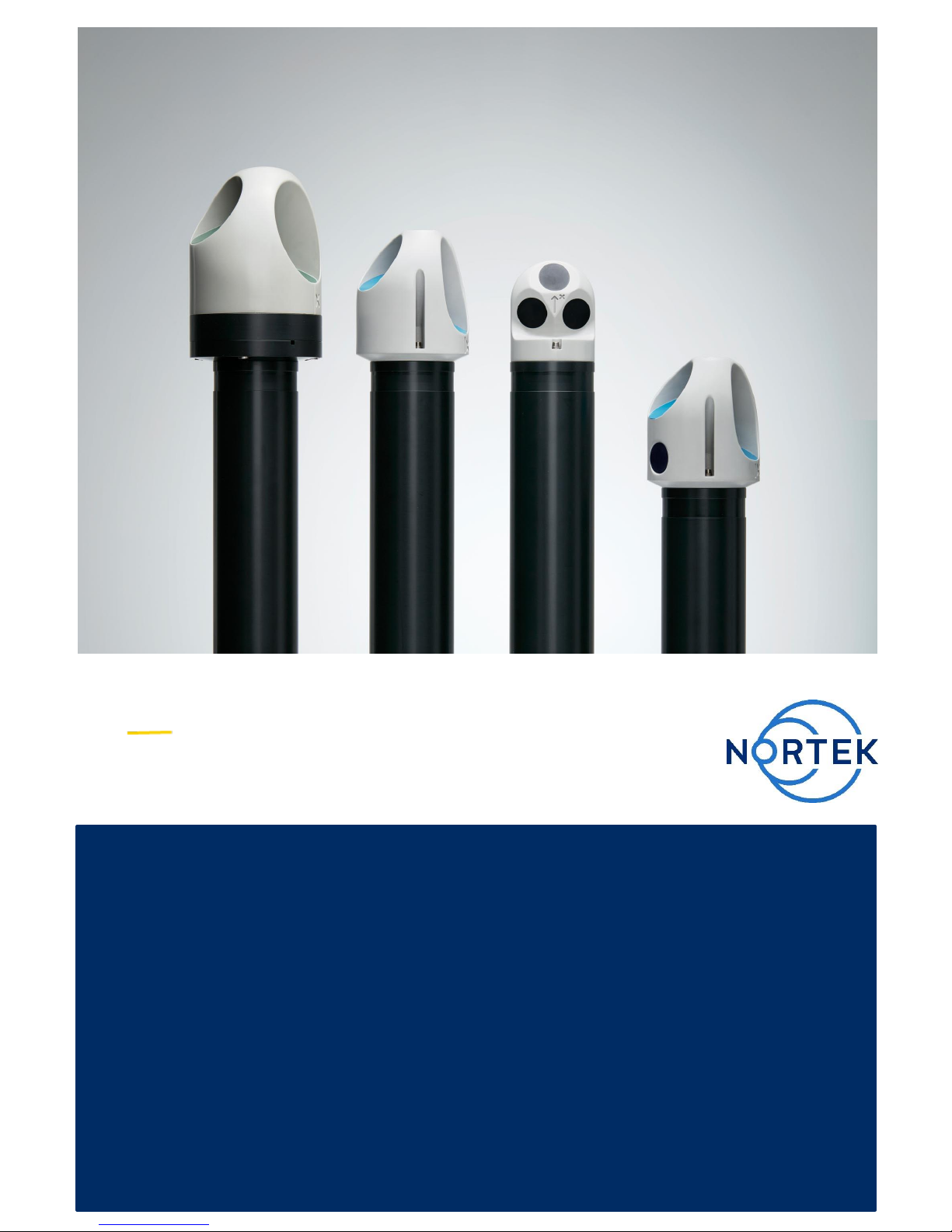
NORTEK QUICK GUIDE
Aquadopp Profiler
Oct. 2017
Page 2

This Quick Guide provides you with the basic information you need to get the
instrument up and running as quickly as possible. If you are familiar with the
Nortek instruments, this guide may be all you need. If you are new to our
instruments and software, you should check out the Nortek Comprehensive
Manual (available on the web), which includes principles of operation,
mounting guidelines, troubleshooting, service manual and simple system
integration. You will also find much useful information in the FAQ site at the
Nortek web: www.nortekgroup.com
Preparation
• Connect the battery/power cable.
• Install the software located on the USB memory stick. Once the
installation is complete, launch the application related to your instrument.
• Run a Functional Test, described in the Service Manual chapter in the
comprehensive manual.
• Set the Pressure Offset: On-line > Set Pressure Offset.
• If there are magnetic materials in proximity to the instrument when
mounted, a calibration of the compass is necessary: On-line > Compass
Calibration.
• Erase the recorder in advance of every deployment.
Deployment Planning
• Select Deployment Planning.
• The activated dialog contains all parameters required to specify the
operation of the instrument. The Deployment Planning frame on the righthand side of the dialog displays performance parameters that are
automatically updated as you change the settings. Use the Standard
configuration to plan your deployment unless you have a very good
reason to move to Advanced. The latter increases the flexibility but so
does the risk of making mistakes. Note that the Use Advanced Settings
box (in the Standard tab) must be checked for the advanced settings to be
effective. A description of each parameter can be found in the application
help, accessible from the dialog box.
• When finished, press OK to accept the changes. By using the Open/Save
commands in the File menu (or the corresponding toolbar buttons) the
deployment parameters can be saved to file at any given time and reloaded when it is time to deploy the instrument.
Start Recorder Deployment
• Establish communication with the instrument.
• Select Start Recorder Deployment, either from the pull-down menu or
from the toolbar.
• Specify the date and time to start the data recording.
• In the Name field, enter up to six characters of text to identify the data file
stored in the recorder.
• In the File Comment box, enter up to 180 characters of text that will be
included in the data file for documenting the data set.
• After pressing OK, the Set Clock dialog box is displayed. We recommend
setting the clock to PC time. The time reference is especially important to
ensure proper synchronization between the instrument and other data
sets collected independently. Time spent on setting the time properly
before a deployment can save a lot of time in post processing and
analysis.
• Press Yes to continue. A confirmation dialog will display the deployment
parameters and allow you to verify that the set-up is what you intended.
• Press Confirm to send the configuration to the instrument. The instrument
will verify that the deployment has started. The configuration information
from the deployment sequence is saved in a log file that has the same
name as the deployment.
Please check that all
expected items are
included in the shipment:
The instrument
External power/signal cable
NORTEK equipment storage
box/toolkit
USB to serial converter
AC/DC voltage transformer
Power cable
(European or American)
Battery harness for 2x batteries
Software on USB memory stick
Final test check list
Packing list
Warranty card
Install the Nortek software
The instrument’s software is
located on the attached
memory stick.
Please check the web
regularly for updates on both
software and firmware.
Page 3

Stop Recorder Deployment
Select Stop Recorder Deployment. When data acquisition has stopped, a
dialog box will display the current AWAC and PC clock time.
Data Retrieval
Select Recorder Data Retrieval.
The recorder overview dialog will show a list of all files currently stored in the
recorder, including the time of the first measurement and the size for each
file.
Select a file in the list by clicking on the filename. Press Retrieve to specify
the name and disk location of the file.
Data Conversion
To convert binary data files retrieved from the recorder to a readable ASCII
format, select Data Conversion.
Add files to the Files to convert list by using the Add file... file selection
dialog. Select the file to convert in the list and press the blue arrow. Specify
the location for the converted files in the Save in folder field. An optional preor postfix that will be added to the recorder filename may be specified. Select
from the View files drop-down list to open the converted (ASCII) files in
Notepad.
On-line Data Collection
Select Start Data Collection from the On-line menu (or press the toolbar
button) to start data acquisition. The real time display shows velocity data
and sensor data as it is collected.
To capture the data that comes in over the serial port to disk select Disk
Recording… from the On-line menu and define the name of a file (without
extension). Once this disk file is defined, the Start Disk Recording and Stop
Disk Recording menu items and toolbar buttons will be enabled.
Tip! Check the retrieved data before deploying the instrument for the second
time. If something is wrong with the instrument, the configuration or the
deployment, this will be detected and the possibility of making the same mistake
twice is avoided.
Mounting
Proper mounting of the instrument is crucial for successful collection of data.
Please mount the instrument in accordance with the Mounting Guidelines.
Basic principles
The instrument measures
current speed and direction
by transmitting sound waves
that are reflected by particles
drifting with the currents in
the water. The Doppler shift
of the return signal is
proportional to the velocity
component along the beams.
By combining the Doppler
shifts from the beams, 2D (2
beams) or 3D (3 beams)
velocity is calculated.
Measuring waves
Both the Aquadopp Current
Meter and Aquadopp Current
Profiler can measure waves
using the PUV method. The
pressure measurement
provides a means of
estimating all the nondirectional wave parameters,
while the combined P, U, and
V measurements allow for
estimating the directional
wave parameters. These
data need to be post
processed.
Data analyses
The software supplied has
been designed to provide
you with the ability to set the
instrument up for
deployment, upgrade the
firmware, download acquired
data and do a quality
assurance of them. The data
can be converted to ASCII
files that can be imported
into various post-processing
programs. In addition, Nortek
has developed a series of
real time and postprocessing software
packages that simplifies your
analyzing work. These can
be downloaded from our
website. Contact Nortek for
valid license key.
Page 4
Cables
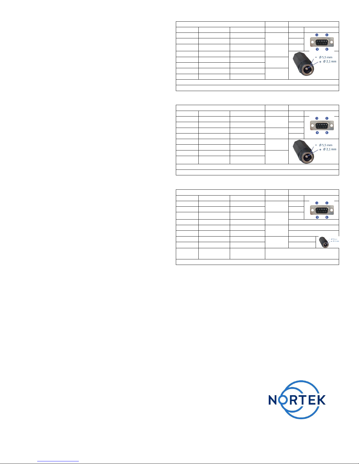
Our instruments are mostly shipped with RS232
communication. RS422 is used for cables longer than
50 m. The wiring is shown in the tables to the right.
The output can either be in ASCII, in fixed NMEA
format, or binary format.
Communication baud rate: 300-115200 (user setting).
Recorder download baud rate: 600/1200 kBaud.
Ensure that the connectors and dummy plugs are
lubricated with dielectric silicone. We recommend 3M
silicone spray. Note that the silicone grease included
in the shipment should be used on the O-rings only.
Analog Input (default for most instruments)
The instrument can read two analog inputs at the
same time. The input range is 0-5V, corresponding to
0-65535 counts in the data file.
Power
• DC Input: 9-16 VDC
• Battery DC-input: Nominal voltage: 13.5-18V
• Absolute maximum DC input voltage: 18.6 V
System Integrator Manual
For more information on how to control a Nortek
product with a non-PC controller, a System Integrator
Manual is available on the website.
Troubleshooting
As most problems are caused by simple mistakes,
please initially check if
• you have forgotten to power the system
• the connector has fallen out of the computer
• you are using the wrong serial port
When all obvious mistakes are ruled out, please turn
to our Troubleshooting Guide. The FAQ site may
also be helpful.
If the problem is still present contact Nortek
support at [email protected]
Underwater Connector
Termination
Pin. No
Wire Color
Purpose
Pins
Description
3
black
RS232 Tx
Twisted
Pair
2
4
white
RS232 Rx
3
5
black
RS232 Gnd
Twisted
Pair
5
6
white/purple
Power Output
7
black
Analogue Ch. 2
Twisted
Pair
8
white/orange
Analogue Ch. 1
1
black
Power Gnd
Twisted
Pair
2
white
Power +
Screen terminated at pin 1 in underwater connector, unterminated at PC side.
Ref: N2100-002A
Underwater Connector
Termination
Pin. No
Wire Color
Purpose
Pins
Description
3
black
RS422 Tx +
Twisted
Pair
7
4
white
RS422 Tx -
2
7
black
RS422 RX -
Twisted
Pair
8
8
white/orange
RS422 RX+
3
5
black
Sync. Out
Twisted
Pair
6
white/purple
Sync. In
1
black
Power Gnd
Twisted
Pair
2
white
Power +
Screen terminated at pin 1 in underwater connector, unterminated at PC side.
Ref: N2100-108
Underwater Connector
Termination
Pin. No
Wire Color
Purpose
Pins
Description
3
black
RS232 Tx
Twisted
Pair
2 4
white
RS232 Rx
3
5
Black
Ground
Twisted
Pair
5
6
white/purple
Analogue Z*
Red wire
7
Black
Analogue X
Twisted
Pair
Green wire
8
white/orange
Analogue Y
Yellow wire
1
black
Power Gnd
Twisted
Pair
Black wire
2
white
Power +
White wire
Screen
Bare
Ground
3 bare wires for grounds, connected
internally to power ground.
Ref: N2100-004
Wiring of RS232 with option for analogue outputs.
*Optional version outputs pressure instead of Z-velocity
 Loading...