

Page 1
© Nortech Management Ltd, United Kingdom
August 2018
www.nortechonline.co.uk
Doc ref: D_002333
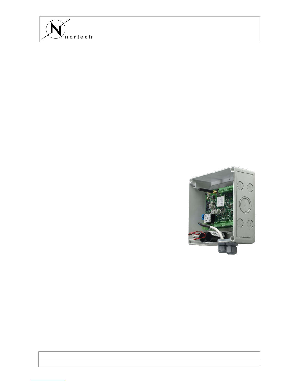
NX12
Micro GSM RTU
USER MANUAL
Version 1.8
Page 2

NX12
Micro GSM RTU
© Nortech Management Ltd, United Kingdom
Page 2 of 25
Publication Notice
Copyright © Nortech Management Limited (NML). All rights reserved. No part of
this publication may be reproduced, stored in a retrieval system, or transmitted in
any form or by any means, including photocopying, electronic, mechanical,
recording or otherwise, without the prior written permission of the copyright holder.
NML provide this document as is, without warranty of any kind either expressed or
implied including, but not limited to, the implied warranties of merchantability and
fitness for a particular purpose. NML may make changes or improvements in the
software, equipment, or specifications described in this document at any time and
without notice. These changes may be incorporated in new releases of this
document.
This publication could contain technical inaccuracies or typographical errors. NML
shall not be liable for any damages (including, but not limited to, consequential,
indirect or incidental, special damages or loss of profits or data) even if NML have
been informed of their potential occurrence, arising out of or in connection with this
document or its use.
English Edition
IBM PC is a trademark of International Business Machines Inc.
Windows is a trademark of Microsoft Corporation.
All other trademark names used in this manual are hereby acknowledged.
Page 3

NX12
Micro GSM RTU
© Nortech Management Ltd, United Kingdom
Page 3 of 25
Contents
1 Safety & notices ....................................................................................... 5
1.1 Safety ............................................................................................... 5
1.2 Qualified users ................................................................................... 5
1.3 Notices .............................................................................................. 5
1.4 Versions ............................................................................................ 5
2 NX12 RTU Description ............................................................................... 6
2.1 Applications ....................................................................................... 6
2.2 Central iHost User Interface ................................................................. 6
2.3 Communications ................................................................................. 6
3 NX12 RTU Set-up Requirements ................................................................. 7
3.1 Auxiliary power supply ........................................................................ 7
3.2 Battery Operation ............................................................................... 7
3.3 USB Port / Field Support Kit ................................................................. 7
4 NX12 RTU Firmware Functions .................................................................... 9
4.1 Clock ................................................................................................ 9
4.2 Inputs / Outputs ................................................................................. 9
4.3 Auxiliary Supply On/Off ....................................................................... 9
4.4 Binary Inputs ..................................................................................... 9
4.5 Counter Inputs ................................................................................. 10
4.6 Analogue Inputs ............................................................................... 10
4.7 Output Channels ............................................................................... 11
4.8 RS485 Modbus ................................................................................. 11
4.9 RTU / Communication Events ............................................................. 11
4.10 Data Log Sizes ............................................................................... 11
4.11 Input monitoring during iHost calls .................................................. 11
4.12 Connection between the RTU and iHost ............................................ 11
4.13 Reconfiguration of the RTU settings.................................................. 12
5 NX12 RTU Operation ............................................................................... 13
5.1 Cold Start ........................................................................................ 13
5.2 LED Indicators .................................................................................. 13
5.3 RTU connection to the iHost system .................................................... 13
5.4 Call Retry Algorithm .......................................................................... 13
6 Installation ............................................................................................ 15
6.1 Qualified Users ................................................................................. 15
6.2 AC Powered Models ........................................................................... 15
Page 4

NX12
Micro GSM RTU
© Nortech Management Ltd, United Kingdom
Page 4 of 25
6.3 DC Powered Models .......................................................................... 15
6.4 Procedure ........................................................................................ 15
6.5 Circuit Board Layout ......................................................................... 15
6.6 PCB Connections .............................................................................. 16
6.7 Wiring Connection Diagrams .............................................................. 18
6.7.1 Digital Inputs ............................................................................. 18
6.7.2 Analogue Inputs ......................................................................... 19
6.7.3 Output Channels ......................................................................... 20
6.8 Enclosure and mounting .................................................................... 21
6.8.1 DIN Rail option ........................................................................... 21
6.8.2 Enclosure option ......................................................................... 21
7 Maintenance .......................................................................................... 22
7.1 Technical assistance .......................................................................... 22
7.2 Communications test ........................................................................ 22
7.3 I/O tests .......................................................................................... 22
7.4 Replacing the Battery ........................................................................ 22
7.5 Recycling ......................................................................................... 23
8 Specification Data .................................................................................. 24
8.1 General ........................................................................................... 24
8.2 AC powered units ............................................................................. 24
8.3 DC powered units ............................................................................. 24
8.4 EMC ................................................................................................ 25
8.5 Environmental .................................................................................. 25
Page 5

NX12
Micro GSM RTU
© Nortech Management Ltd, United Kingdom
Page 5 of 25
1 Safety & notices
1.1 Safety
For AC supply variants:
The AC supply should be isolated prior to opening the enclosure and should not be
reconnected until the enclosure lid is secured.
Isolate from Mains before removing cover.
1.2 Qualified users
Users should ensure they are suitably trained and qualified prior to working on the
NX12.
Installation should be carried out in accordance with local procedures and company
safety and operational guidelines.
1.3 Notices
Battery
Do not attempt to charge the battery – risk of
explosion. Do not short circuit, crush,
disassemble or heat above 100°C, incinerate or
expose contents to water.
AC Supply
(only applies to AC
powered models)
Isolate from Mains before removing cover.
100-240V AC
50-60Hz
100mA rated current
DC Supply
(only applies to DC
powered models)
12-24V DC
500mA rated current
Disposal
Battery and NX12 unit should be disposed of in
accordance with local regulations.
1.4 Versions
This document describes the current build version and software functionality of the
NX12 product. Earlier versions and software releases may differ. Please consult
Nortech for earlier versions of this document.
Page 6

NX12
Micro GSM RTU
© Nortech Management Ltd, United Kingdom
Page 6 of 25
2 NX12 RTU Description
2.1 Applications
The NX12 RTU (Remote Terminal Unit) is a telemetry device that is suitable for use
in fixed site alarm monitoring and control applications.
The NX12 provides monitoring and control of equipment via digital inputs, counter
inputs, analogue inputs, control outputs and RS485 (using Modbus RTU). Typical
applications include:
▪ LV substation monitoring and control.
▪ Pump and pump station monitoring.
▪ Wind farm site monitoring.
▪ General plant alarm panel monitoring.
▪ Tank level monitoring.
▪ Circuit breaker operation monitoring.
▪ Fault Passage Indicator monitoring.
2.2 Central iHost User Interface
The NX12 is remotely monitored from the Nortech “iHost” system. Users access
iHost via a unique username and password. The iHost system stores and displays
equipment status and alarm data, along with related event history and statistics. It
also provides remote NX12 configuration tools. Data is displayed in lists, record
details, maps, diagrams, tables and graphs.
For larger customers, a dedicated private iHost System can be installed at their own
premises on their own servers.
The functionality of the iHost User Interface is beyond the scope of this document.
2.3 Communications
The NX12 includes an in-built, quad-band GPRS wireless modem and antenna.
There are 3G and 4G factory options available for different regions – please contact
Nortech to discuss your requirements.
Page 7

NX12
Micro GSM RTU
© Nortech Management Ltd, United Kingdom
Page 7 of 25
3 NX12 RTU Set-up Requirements
3.1 Auxiliary power supply
The NX12 requires an auxiliary AC or DC supply (factory set option).
AC powered units
The NX12 requires a two (2) wire AC supply. Observe correct polarity.
It is the users’ responsibility to ensure local wiring regulations are complied with
during installation.
AC powered units may be fitted with a long life, non-rechargeable, lithium battery
to power the unit when the AC supply is off.
Suitable batteries and replacements are available from Nortech.
DC powered units
The NX12 requires a 12-24V DC supply. Observe correct polarity.
It is the users’ responsibility to ensure local wiring regulations are complied with
during installation.
DC powered units may be fitted with a long life, non-rechargeable, lithium battery
to power the unit when the DC supply is off.
Suitable batteries and replacements are available from Nortech.
3.2 Battery Operation
The NX12 monitors its auxiliary power supply. When the auxiliary supply is lost,
provided a battery is connected, the unit will continue to operate as follows:
Condition
Behaviour
First 1 minute after loss
of auxiliary supply
Normal operation.
Modem is switched off once the loss of supply is
reported to the Host.
1 minute to 12 hours
(configurable) after loss
of auxiliary supply
Low power mode:
Modem switched off, will be turned on for
communications as required.
Analogue and Digital Inputs scan rate reduced to
250ms.
RS485 Modbus polling stops.
12 hours (configurable)
after loss of supply
Conserve battery:
Unit auto powers off.
Unit will restart when auxiliary supply returns.
3.3 USB Port / Field Support Kit
The NX12 is normally shipped with the customer’s default parameter values already
configured.
The NX12 provides a USB interface to allow the user to configure operational
parameters from a laptop/PC. Parameters are stored in non-volatile memory (they
are retained during power outages).
Page 8

NX12
Micro GSM RTU
© Nortech Management Ltd, United Kingdom
Page 8 of 25
The NX Field Support Kit (FSK) is a software application that enables users to
interrogate the status and settings of the RTU and to inspect the archived logs.
The principle use of the FSK is to set the connection details that enable
communication between the RTU and the iHost system via a mobile network. This
entails configuring the SIM card(s) within the RTU. Once connection has been
established, the NX12 RTU may be reconfigured remotely from the iHost system.
The NX FSK is described in a separate document.
Page 9

NX12
Micro GSM RTU
© Nortech Management Ltd, United Kingdom
Page 9 of 25
4 NX12 RTU Firmware Functions
The features below describe the functionality offered by the latest version of NX12
firmware at the time of writing.
4.1 Clock
The RTU has an internal Real Time Clock (RTC). The clock is synchronised with the
iHost system clock on a regular basis.
Date/time stamping in Event and System logs is recorded to 10ms in granularity.
4.2 Inputs / Outputs
There are 16 digital inputs. These can be individually configured to operate as
either a Binary Input or as 16-bit Counter Input.
There are 8 analogue inputs with 8-bit resolution.
There are 8 output lines.
The RS485 serial port is used to collect additional data from external devices via
the Modbus RTU protocol – contact Nortech for a list of supported devices.
4.3 Auxiliary Supply On/Off
The incoming auxiliary supply line is monitored. The default setting is to date/time
stamp changes of state (loss / restoration) and to immediately report them to the
iHost system.
A configurable debounce timer can be used to extend the period that the auxiliary
supply must change state before an event is logged and reported.
4.4 Binary Inputs
The following features are supported and remotely configured for each input
individually:
Enabled
The input is monitored.
Status
Closed or Open. Status is reported to the iHost during
every communication.
Debounce
How long the input must be open (or closed) before a
change of state is confirmed.
Log Open
Yes = create a date/time log entry when the input
changes from Closed to Open.
Log Close
Yes = create a date/time log entry when the input
changes from Open to Closed.
Report on Open
Yes = initiate an immediate iHost communication as
soon as an Open event is generated.
Report on Close
Yes = initiate an immediate iHost communication as
soon as a Close event is generated.
In ideal conditions, the processor detects changes of state within 10ms.
Page 10

NX12
Micro GSM RTU
© Nortech Management Ltd, United Kingdom
Page 10 of 25
4.5 Counter Inputs
The following features are supported and remotely configured for each input
individually:
Enabled
The input is monitored.
Current Value
A 16-bit number which is converted to a 32-bit number
with scaling at the iHost system. The current value is
reported to the iHost system during every
communication. When the 16-bit maximum is reached
the counter rolls back to zero and continues.
Debounce
How long the input must be open (or closed) before a
change of state is confirmed.
Increment on Open
Yes = increment the current value by 1 when the input
changes from Closed to Open.
Increment on Close
Yes = increment the current value by 1 when the input
changes from Open to Closed.
30-min Datalogging
Yes = create a data log entry for the input with how
many counts the current value increased by for each
30-minute period of the day. The 30-minute data logs
are reported to the iHost system during routine
communications.
In ideal conditions, the processor detects changes of state within 10ms.
4.6 Analogue Inputs
The following features are supported and remotely configured for each input
individually:
Enabled
The input is monitored.
Level
An 8-bit value. The Level is reported to iHost during
every communication.
Routine Datalogging
Yes = Take a date/time stamped routine level reading at
the frequency specified (1 min to 24 hours). Date/time
entries are reported during the next iHost
communication.
Dead band Crossing
Logging
Each input has a dead-band percentage. When the level
changes by an amount exceeding the dead-band, the
RTU adds a date/time stamped entry in the analogue
input log.
Threshold Crossing
Logging
Each input has 4 threshold levels providing 5 zones.
When the level crosses a threshold, the RTU adds a
date/time stamped entry in the analogue input log.
Report on Dead band
Yes = initiate an immediate iHost communication as
soon as a dead-band-crossed event is generated.
Report on Threshold
Yes = initiate an immediate iHost communication as
soon as a threshold-crossed event is generated.
Debounce
How long the input must be in a new zone (or deadband) before a threshold crossing (or dead-band
crossing) is confirmed.
Page 11

NX12
Micro GSM RTU
© Nortech Management Ltd, United Kingdom
Page 11 of 25
In ideal conditions the processor scans the analogue inputs every 10ms.
4.7 Output Channels
The following features are supported and remotely configured for each switched
output channel. It is expected that applications will use the Output Channels to
drive external relays:
Energise
Energises the output. Has no effect if output is already
energised.
De-energise
De-energises the output. Has no effect if output is
already de-energised.
Energise Pulse
Energises, pauses, then de-energises the output.
De-energise Pulse
De-energises, pauses, then energises the output.
Pulse Duration
Configurable pulse width from 50ms to 12.75 seconds in
50ms increments.
4.8 RS485 Modbus
The NX12 uses the Modbus RTU protocol to poll for data from connected Slave
devices. Modbus I/O mappings are loaded into the NX12 using a script file. Please
contact Nortech for assistance configuring the Modbus interface.
4.9 RTU / Communication Events
GSM signal strength is reported to the iHost system. Communication failures are
date/time stamped, logged and reported to the iHost system.
The PCB temperature within the RTU is also reported to the iHost system.
4.10 Data Log Sizes
Data logs are stored in non-volatile memory and include local date/time stamps.
▪ Binary Input Log – 1024 date/time stamped entries.
▪ Counter Input Log – 1024 date/time stamped entries.
▪ Analogue Input Log – 1024 date/time stamped entries.
▪ RTU Events Log – 1024 date/time stamped entries.
▪ Counter 30-minute Data Logs – 256 date/time stamped entries.
When a log entry fills, a “buffer overrun” event is logged (to identify a loss of data)
and then the log loops back and overwrites the oldest data. Buffer overrun log
entries are themselves date/time stamped and reported to the iHost system.
4.11 Input monitoring during iHost calls
Inputs continue to be monitored during calls to the iHost system. Depending upon
the log configuration, this may result in an immediate new call to the iHost system.
4.12 Connection between the RTU and iHost
During contact with the iHost system, the RTU performs the Slave function, serving
information upon request from the iHost system, which performs the Master
function. Data is transferred, in each direction, using a secure protocol.
Page 12

NX12
Micro GSM RTU
© Nortech Management Ltd, United Kingdom
Page 12 of 25
Information from the RTU is stored in the iHost database, where it may be viewed
by users.
4.13 Reconfiguration of the RTU settings
The operational behaviour of the RTU, including which inputs are enabled and how
data is reported and stored, is configurable from the iHost system and hence does
not require a site visit.
When an iHost User makes changes to these settings, the new settings will be
loaded into the RTU during the next contact between the iHost system and the RTU.
Page 13

NX12
Micro GSM RTU
© Nortech Management Ltd, United Kingdom
Page 13 of 25
5 NX12 RTU Operation
5.1 Cold Start
The RTU is configured to monitor for a processor power-up event, occurring after
periods without mains and battery back-up power. This is known as a “Cold Start”.
The RTU will then initiate communication with the iHost system.
5.2 LED Indicators
The processor LEDs are used to indicate both the operational state and the
communication state of the RTU.
Diagnostic LED
Condition
Meaning
LED1 (top)
Steady Flashing
Processor working.
LED1
On for 5 seconds
Communication to host successfully
completed.
LED1
Quick Flash
TX Host/Modem Data.
LED2
Steady Flashing
Last communication failed. In retry
sequence.
LED2
On for 5 seconds
Communication to host failed.
LED2
Quick Flash
RX Host/Modem Data.
LED3
Quick Flash
RS485 TX Data.
LED4
Quick Flash
RS485 RX Data.
Led 5 (bottom)
various
Driven directly by the modem.
5.3 RTU connection to the iHost system
The NX12 RTU connects to the iHost system when:
▪ An event that is configured to initiate a connection occurs.
▪ The “Next Routine Call” date/time is reached or exceeded.
▪ The user presses the test button (PCB identifier SW1).
A configurable “Routine Health Check Interval” is configured by the iHost system.
Typically, this is set between 1 hour and 3 hours, however the range for the
interval setting is from 1 minute to 28 days.
An event configured to cause an immediate communication to the iHost system will
do so regardless of when the next routine health check is due.
5.4 Call Retry Algorithm
If a connection to the iHost system fails, then the RTU enters its retry sequence.
The RTU retries in a block of 10 attempts, approximately 1 minute apart. Then it
waits a (re)configurable time before starting another block of 10 attempts. This
repeats until communications is restored.
During this period, if any new events configured as “Immediate Contact Host”
occur, then the RTU will immediately start attempting to contact the iHost system.
Page 14

NX12
Micro GSM RTU
© Nortech Management Ltd, United Kingdom
Page 14 of 25
Failed communication attempts are date/time stamped by the RTU, along with the
reason for the failure. These logs are reported to the iHost system upon the next
successful contact.
Page 15

NX12
Micro GSM RTU
© Nortech Management Ltd, United Kingdom
Page 15 of 25
6 Installation
6.1 Qualified Users
Users should ensure that they are suitably trained and qualified prior to working on
the RTU.
6.2 AC Powered Models
The AC supply should be isolated prior to opening the enclosure and should not be
reconnected until the enclosure lid is secured.
The AC Power Supply should be rated at 230 Volts or 115 Volts, operating at a
frequency of 50Hz.
The power supply to the RTU should be:
▪ Connected via a switch or circuit breaker.
▪ Close to the RTU and within easy reach of an operator.
▪ Marked as the disconnection device for the RTU.
6.3 DC Powered Models
The DC Power Supply should be rated at 12 Volts or 24 Volts.
6.4 Procedure
The following steps must be completed in the order set out below.
1. Configure the NX12 prior to installation (this may be done at the factory).
2. Connect the external equipment to be monitored to the I/O terminals on the
NX12.
3. Connect the auxiliary power supply (do not switch it on yet).
4. Connect the battery (if one is required).
5. Secure the NX12 lid (for units with an enclosure).
6. Switch on auxiliary power. Confirm that the NX12 RTU successfully
communicates with the iHost system.
7. Test the unit by confirming that all inputs and outputs report the correct
status and events.
8. Confirm that at least two calls to the iHost system are successful (this ensures
that the settings are synchronised).
9. If a lithium battery is included:
▪ Remove the auxiliary supply and confirm that the RTU continues to operate
using battery power.
▪ Restore the auxiliary supply.
6.5 Circuit Board Layout
The Printed Circuit Board (PCB) hardware is manufactured as shown in the diagram
below.
Page 16

NX12
Micro GSM RTU
© Nortech Management Ltd, United Kingdom
Page 16 of 25
Ensure that the correct auxiliary supply is provided for the model being used.
Where fitted, the battery should be plugged in.
Digital Inputs should be volt-free dry contacts.
Analogue Inputs should be 4-20mA (factory option for 0-10V).
Output channels can switch up to 100mA.
NX12 Terminal Blocks, Sockets, Plugs
SK2
TB4
TB2 TB1
TB5 TB3
SK4
TB6
SK3
SW1 PL2
H1
LED 1
LED 5
...
SK1
X
PL1
TB7
Pin 1Pin 1Pin 1Pin 1Pin 1
Pin 1 Pin 1
X X
6.6 PCB Connections
PCB Ref.
Pin
Function
Comment
TB7
1
AC Supply Live (110-230V AC)
Unit is factory set as
either AC powered or
DC powered unit.
TB7
2
AC Supply Neutral
TB6
1
DC supply +ive (12-24V DC)
TB6
2
DC supply 0V
PL2
-
Lithium battery
SW1
-
User button
Page 17

NX12
Micro GSM RTU
© Nortech Management Ltd, United Kingdom
Page 17 of 25
PCB Ref.
Pin
Function
Comment
SK2
-
Micro USB
SK3
-
GSM SMA antenna connector
SK4
-
SIM card carrier
TB4
1
Not connected
TB4
2
Digital Input #8
TB4
3
Digital Input #7
TB4
4
Digital Input #6
TB4
5
Digital Input #5
TB4
6
Digital Input #4
TB4
7
Digital Input #3
TB4
8
Digital Input #2
TB4
9
Digital Input #1
TB4
10
Common
TB2
1
Not connected
TB2
2
Digital Input #16
TB2
3
Digital Input #15
TB2
4
Digital Input #14
TB2
5
Digital Input #13
TB2
6
Digital Input #12
TB2
7
Digital Input #11
TB2
8
Digital Input #10
TB2
9
Digital Input #9
TB2
10
Common
TB3
1
Do not use
TB3
2
Analogue Input #8
TB3
3
Analogue Input #7
TB3
4
Analogue Input #6
TB3
5
Analogue Input #5
TB3
6
Analogue Input #4
TB3
7
Analogue Input #3
TB3
8
Analogue Input #2
TB3
9
Analogue Input #1
TB3
10
Common
Page 18

NX12
Micro GSM RTU
© Nortech Management Ltd, United Kingdom
Page 18 of 25
PCB Ref.
Pin
Function
Comment
TB5
1
Not connected
TB5
2
Digital Output #8
TB5
3
Digital Output #7
TB5
4
Digital Output #6
TB5
5
Digital Output #5
TB5
6
Digital Output #4
TB5
7
Digital Output #3
TB5
8
Digital Output #2
TB5
9
Digital Output #1
TB5
10
Common
TB1
1
RS485 TX/RX +ive
TB1
2
RS485 TX/RX -ive
TB1
3
RS485 + wake up
Not implemented
TB1
4
RS485 Ground/Common
PL1
1-6
Programming port
Do not use
H1
1-16
Expansion header
SK1
-
Not used
6.7 Wiring Connection Diagrams
6.7.1 Digital Inputs
Connecting the RTU to a volt-free dry contact input
Input n
Common
RTU Digital
Input Terminals
Equipment
Monitored
Page 19

NX12
Micro GSM RTU
© Nortech Management Ltd, United Kingdom
Page 19 of 25
6.7.2 Analogue Inputs
Connecting the RTU to a 2-wire sensor (4-20mA)
Input n
18V
+
RTU Analogue
Input Terminals
Transducer / Sensor
-
Connecting the RTU to a 4-wire sensor (4-20mA)
Input n
Common
+
RTU Analogue
Input Terminals
Transducer / Sensor
-
+
Sensor 4-20mA
output signal
Sensor power
supply
18V
-
Page 20

NX12
Micro GSM RTU
© Nortech Management Ltd, United Kingdom
Page 20 of 25
6.7.3 Output Channels
Outputs switch 100mA.
Example connecting the RTU to an external relay
Output n
Common
RTU Output
Terminals
External
Relay
V +
0V
DC Supply
Equipment
Controlled
-
Connect dotted line when
additional back emf protection
required when switching inductive
loads, for example relays.
Page 21

NX12
Micro GSM RTU
© Nortech Management Ltd, United Kingdom
Page 21 of 25
6.8 Enclosure and mounting
6.8.1 DIN Rail option
NX12 supplied as a DIN rail mountable unit
6.8.2 Enclosure option
NX12 supplied in an IP54 polycarbonate enclosure
180.0mm
182.0mm
165.0mm
7.5mm
FRONT OF ENCLOSURE
90 mm DEPTH
REAR OF ENCLOSURE
SHOWING 4 FIXING HOLES
167.0mm
Ø 4.5mm
7.5mm
Page 22

NX12
Micro GSM RTU
© Nortech Management Ltd, United Kingdom
Page 22 of 25
7 Maintenance
The Auxiliary supply should be isolated prior to opening the enclosure and should
not be reconnected until the enclosure lid is secured.
7.1 Technical assistance
In case of technical assistance please contact either the supplier of the NX12 or
Nortech. If a malfunction occurs, please contact Nortech.
Please see www.nortechonline.co.uk for contact details.
7.2 Communications test
Press the button (SW1) at the top left of the PCB. Confirm that the RTU
communicates successfully with the iHost system.
7.3 I/O tests
For each input connected to the NX12, confirm that the correct status data and the
desired date/time events are being reported to the iHost system.
7.4 Replacing the Battery
When replacement is necessary, contact Nortech for a replacement part.
There are two types of battery, depending on the PCB hardware version:
2 pin battery connectors
NX12’s with 2 pin battery
connectors require 3.6V lithium
battery:
▪ Part number: ACC-0751
3 pin battery connectors
NX12’s with 3 pin battery
connectors require 7.2V lithium
battery:
▪ Part number ACC-1010
To replace the battery, unplug the old battery pack and plug in the new pack.
Re-test the NX12 unit for correct operation.
Page 23

NX12
Micro GSM RTU
© Nortech Management Ltd, United Kingdom
Page 23 of 25
7.5 Recycling
After replacing the internal battery, dispose of the old lithium battery responsibly,
in accordance with local rules.
NX12 units can be returned to Nortech for recycling at the end of their life.
Page 24

NX12
Micro GSM RTU
© Nortech Management Ltd, United Kingdom
Page 24 of 25
8 Specification Data
8.1 General
AC supply
(AC powered units only)
100-240V AC, 50-60Hz.
100mA rated current.
See additional information below.
DC supply
(DC powered units only)
12-24V DC.
500mA rated current.
Battery
(where connected)
Lithium-thionyl chloride (Li-SOCl2).
Nominal 5.8Ah.
3.6V single cell pack. Lithium content approx. 3.4g.
7.2V twin cell pack. Lithium content approx. 6.8g.
Maintenance interval 10 years or when exhausted.
Local Indication
Surface mount LEDs.
Hardwired Digital Inputs
Qty 16. Configurable as alarm or counter inputs.
Hardwired Digital
Outputs
Qty 8. Transistor outputs.
Hardwired Analogue
Inputs
Qty 8. 0-25mA inputs. Configurable alarm thresholds.
Additional I/O
Additional I/O is achieved via the RS485 Modbus
interface.
Local Serial Data
Modbus over 3 wire RS485.
Remote Indication
GSM modem with SMA antenna. NEXUS protocol,
supported on the iHost system.
8.2 AC powered units
The NX12 requires a two (2) wire AC supply. Connect with the correct polarity.
It is the users’ responsibility to ensure that local wiring regulations are complied
with during installation.
It is recommended that a Ferrite be fitted to the AC power cable (suitable part
Wurth Elektronik, PN 742 700 44).
The power supply to the RTU should be:
1. Connected via a switch or circuit breaker.
2. Close to the RTU and within easy reach of an operator.
3. Marked as the disconnection device for the RTU.
8.3 DC powered units
The NX12 requires a DC supply. Connect with the correct polarity.
It is the users’ responsibility to ensure that local wiring regulations are complied
with during installation.
Page 25

NX12
Micro GSM RTU
© Nortech Management Ltd, United Kingdom
Page 25 of 25
8.4 EMC
The NX12 has been designed and manufactured to meet the following standards.
Emissions EN61326-1: 2006 Class B Emissions, Industrial locations
EN55011 Mains terminal disturbance voltage
EN55011 Electromagnetic radiation disturbance
EN61000-3-2 Harmonic current emissions
EN61000-3-3 Flicker (not applicable)
Immunity EN61326-1:
EN61000-4-2 ESD
EN61000-4-3 EM Field
EN61000-4-4 Burst
EN61000-4-6 Conducted RF
EN61000-4-8 Power Frequency Magnetic Field
EN61000-4-11 Voltage Dips and Interruptions
8.5 Environmental
Enclosure Rating: IP54
Humidity: 0-95% non-condensing
Temperature: PCB: -20 to +70 degrees C.
Battery: -60 to +85 degrees C.
GSM modem: -40 to +85 degrees C.
Storage: The NX12 should be stored in an environment that is dry,
corrosive-free, and not in direct sunlight.
Correct storage prevents premature component failures
caused by environmental factors such as moisture or corrosive
gases. Exposure to high humidity or corrosive environments
will prematurely degrade the electronic components in any
electronic device regardless of its use or manufacturer.
 Loading...