

Page 1

2-Reader Access Controller
CRC200R
USER GUIDE
REF No.: UG-CRC200R
ISSUE: 02
March 2009
Page 2

CRC200R USER GUIDE ISSUE 02
1-2
Page 3

CRC200R USER GUIDE ISSUE 02
Contents
Contents.........................................................................................................................................1-1
1 SCOPE....................................................................................................................................1-1
2 INTRODUCTION.....................................................................................................................2-1
2.1 Overview..........................................................................................................................2-1
2.2 Features...........................................................................................................................2-1
3 INSTALLATION.......................................................................................................................3-1
3.1 Mounting the Unit.............................................................................................................3-1
3.2 Power Supply and Cabling Requirements.......................................................................3-2
3.2.1 Power Supply............................................................................................................3-2
3.3 Reader voltage settings...................................................................................................3-3
3.4 Connecting the reader .....................................................................................................3-3
3.5 Output Relay Connections...............................................................................................3-3
3.6 Free Exit Option...............................................................................................................3-3
3.7 Arming and Door Monitoring Options...............................................................................3-4
4 PROGRAMMING THE CRC200R...........................................................................................4-1
4.1 Programming Overview ...................................................................................................4-1
4.2 Main Installation Parameters ...........................................................................................4-2
4.2.1 Date & Time..............................................................................................................4-2
4.2.2 Operating Parameter................................................................................................4-2
4.2.3 Anti-Passback...........................................................................................................4-5
4.3 Programming the Cards...................................................................................................4-5
4.4 Setting PIN Codes ...........................................................................................................4-5
5 PROGRAMMING REFERENCE.............................................................................................5-1
5.1 Program cards .................................................................................................................5-1
5.1.1 Program Cards in Line Mode....................................................................................5-1
5.1.2 Program Cards in 210 Mode.....................................................................................5-2
5.2 Learn Cards.....................................................................................................................5-2
5.2.1 Learning Cards in Line Mode....................................................................................5-3
5.2.2 Learning Cards in 210 Mode ....................................................................................5-4
5.3 Verify Cards.....................................................................................................................5-4
5.4 Set PIN Code...................................................................................................................5-5
5.5 Installer ............................................................................................................................5-6
5.5.1 Configure..................................................................................................................5-6
1-1
Page 4

5.5.2 Set APB Mode ..........................................................................................................5-8
5.5.3 Date/Time .................................................................................................................5-9
5.5.4 Timezones (Door Open Timezones when set to ‘210’)...........................................5-10
5.5.5 Card Format............................................................................................................5-11
5.5.6 Card Test................................................................................................................5-13
5.6 Clear Cards....................................................................................................................5-13
5.7 Clear Events...................................................................................................................5-14
5.8 Timezones (Available only in Mode ‘210’)......................................................................5-15
5.9 Access Levels (Available only in Mode ‘210’) ................................................................5-16
6 CRC200R COMMUNICATIONS .............................................................................................6-1
6.1 Online to Norpass2 ..........................................................................................................6-1
6.1.1 RS485 Connector and Protocol Selection link..........................................................6-1
7 TECHNICAL SPECIFICATIONS............................................................................................. 7-1
Appendix A – Menu Structures..........................................................................................................1
CRC200R USER GUIDE ISSUE 02
Appendix B – Card Formats ..............................................................................................................1
Clock & Data (ISO/ABA Track 2) ...................................................................................................1
Wiegand.........................................................................................................................................1
Appendix C – Card Record Sheet .....................................................................................................1
1-2
Page 5

CRC200R USER GUIDE ISSUE 02
1 SCOPE
This User Guide specifically covers the installation and programming of CRC200R fitted with
firmware version 3.02. For the CRC200S fitted with firmware version 3.02, refer to UG-CRC200S
Issue 02. For earlier versions of CRC200, please refer to User Guide UG-CRC200.
1-1
Page 6

Page 7

CRC200R USER GUIDE ISSUE 02
2 INTRODUCTION
2.1 Overview
The Nortech CRC200R is a two-channel card reader controller that provides the ideal solution to
OEM (original equipment manufacturer) companies that require a controller for their card access
system. It is ideal both for simple card access systems that control vehicle or personnel
movements into and out of car parks or through electronically controlled doors, and for more
complex systems requiring time zones, anti-passback, event logging, etc. It can also be used as
part of a Norpass2 managed access network via a data connection to the Norpass2 management
platform.
The CRC200R can control any reader combination from magnetic stripe, proximity and smart card
plus numeric keypads, biometric devices, long-range RFID systems and RF remote control
systems. It can also support motorised readers with card capture capability for magnetic stripe,
proximity and smart card.
In addition to the standard CRC200 features, the CRC200R supports random card numbers so that
it can be used with cards from existing applications and further enhance the support of mixed
media on the same controller.
2.2 Features
• Supports the connection of two independent readers, each with their own latch relay.
• Capacity for up to 6,550 non-sequential card numbers.
• Individual or batch adding and voiding cards on each reader independently.
• Card number learning
• Capture control option when using card-capture readers.
• Ability to program 10 PIN codes for use with a keypad or reader/keypad combination.
• Output latch relay time selectable from 0.5 second to 30 seconds.
• Independent request to exit input.
• Auxiliary input for arming or for door monitoring when online.
• Accessibility controlled by the use of access levels and time zones.
• Anti-passback with programmable auto reset.
• Anti-timeback with selectable time period from 1 to 30 minutes in 1-minute increments.
• Compact design and easy installation.
• Choice of supply voltages.
• Selectable reader supply output (5 volts or supply voltage)
• Real-time clock
• Supports both Clock & Data and Wiegand card formats.
• Password protection.
• Can be managed by Norpass2 Access Control Software.
2-1
Page 8

Page 9
CRC200R USER GUIDE ISSUE 02
3 INSTALLATION
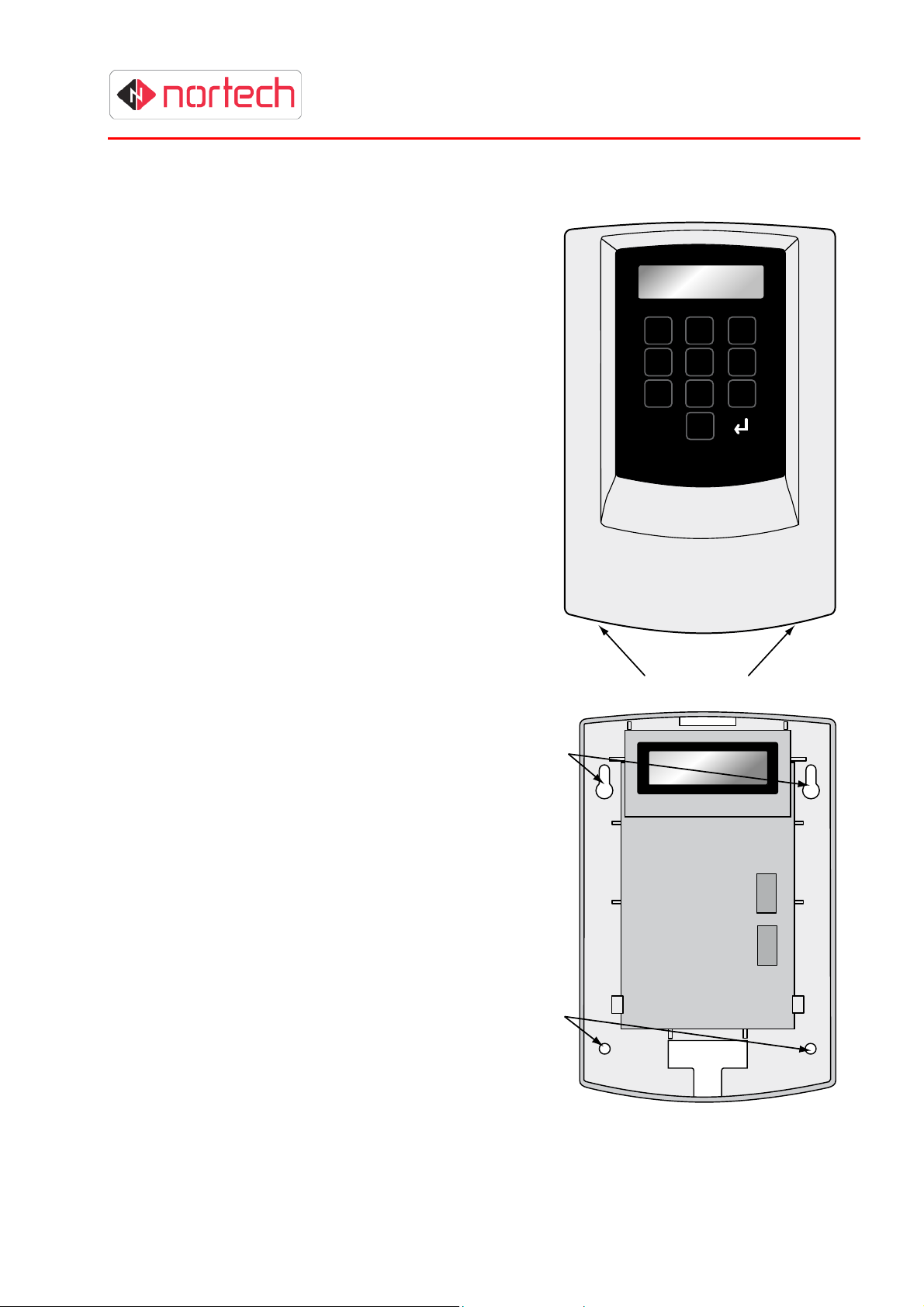
3.1 Mounting the Unit
The CRC200 can be wall-mounted when used indoors or
fixed inside a weatherproof housing for outdoor use.
Identify a location convenient for cabling while ensuring
that the LCD screen and keypad are easily accessible for
programming the unit and carrying out diagnostics. Also
ensure that the CRC200 is protected from excessive
temperatures and moisture.
The mounting procedure is as follows:
1. Release the front cover from the main unit by
pressing the securing buttons at the base of the
unit while you lift off the cover from the bottom
(hinging the cover at the top).
2. Carefully unplug the ribbon cable linking the
cover to the main unit. Avoid pulling or bending
the ribbon cable.
1 2 3
4 5 6
7 8 9
P 0
3. Completely remove the front cover.
4. Mount the unit on the mounting surface through
the 2 keyhole slots and 2 mounting holes in the
back plate. Use 4 appropriate screws or nuts/bolt
(M4) according to the type of mounting
surface.
5. After wiring the unit, support the cover
with one hand and carefully re-insert the
end of the ribbon cable into its socket.
Refit the cover by engaging the top of
the cover with the top of the housing
and hinging in the bottom of the cover
until the securing buttons are fully
engaged in the housing.
Note: If the unit is already mounted in a
plastic enclosure with PSU, mount the
enclosure as follows:
There are 3 mounting holes in the back
panel of the enclosure with an optional
fourth hole at the bottom of the back
panel. Choose a location where there is
sufficient space to run cables into one
or more of the cable apertures
(knockouts provided in top and bottom).
Mount the unit on the planned mounting
surface use 4 appropriate screws or
nuts/bolt (M4) according to the type of
mounting surface.
Retaining Buttons
Keyhole
Slots
Mounting
Holes
3-1
Page 10
V
CRC200R USER GUIDE ISSUE 02
3.2 Power Supply and Cabling Requirements
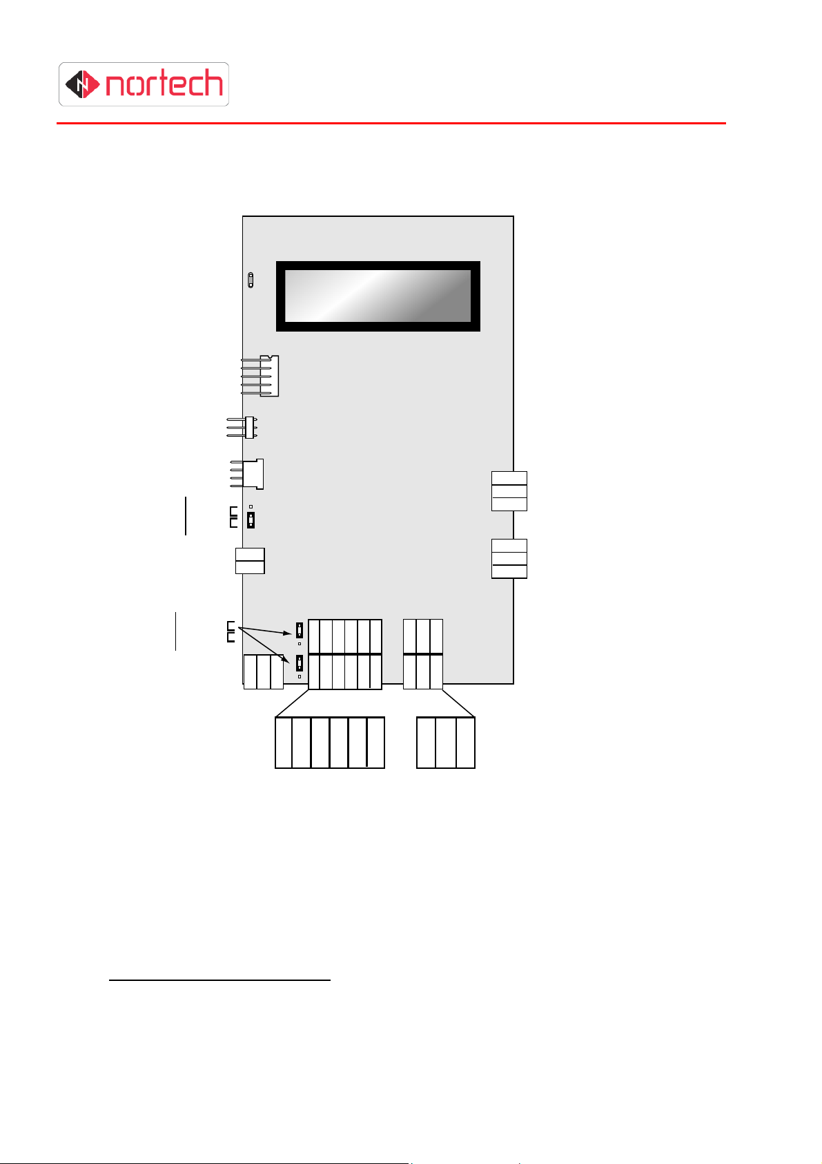
The diagram below shows the CRC200R with the cover removed. All terminal blocks and
configuration jumpers are shown.
NOT
USED
NOT
USED
NOT
USED
Comm’s
Select
12 - 24 VDC
RS232
RS232
RS485
+
-
N/O
N/C
Comm
N/O
N/C
Comm
Relay 1
Relay 2
Reader
oltage
Select
5V
As supply
D-
D+
RS485
Reader 1
GND
-ve
+ve
LED
Dat/D0
Capt
Clk/D1
Reader 2
0v
REX
Mon
Figure 3.1 – CRC200R Connection Diagram
3.2.1 Power Supply
The CRC200R must be fed from a suitable power supply that is capable of supplying a voltage
between 12 and 24 volts DC (see warning below). The supply current requirements for the unit
are100 milliamps quiescent, and 230 milliamps while reading with a passive reader. Some reader
types such as motorised readers need to be powered by a separate supply (refer to the reader’s
installation instructions).
Connect the power supply to the power input connector at the bottom left of the unit (see diagram
above) Do not apply power at this stage.
3-2
Page 11

Warning: Power supply limitations for use of Door Open Timezones feature
It is recommended that the supply voltage is limited to between 12 and 18 volts DC if
the Door Open Timezone feature is to be used (i.e. door relays remaining operated
for several hours). The continuous operation of relays with certain readers connected
may cause unreliable operation of the CRC200R if fed from a 24 volt supply.
Warning: Use of CRC200R with 12V readers
If a 12V DC reader is to be powered from the CRC200R, then the power supply to
the CRC200R must
output is selected, the input +ve pin is connected directly to the reader supply output
pin. If therefore, an incorrectly rated supply is connected to the input, it is likely to
damage the reader when power is applied.
CRC200R USER GUIDE ISSUE 02
be rated at 12V DC. When the “supply voltage” reader supply
3.3 Reader voltage settings
Each of the two reader interfaces includes a power supply output. These power supplies can be
individually set to either 5V or “supply voltage” to match the requirements of the corresponding
reader. The voltage for each reader is set on a jumper to the left of the corresponding terminal
block. The factory setting for these jumpers is 5 volts. To avoid damage to the readers, you must
set the correct voltage for each reader before applying power to the CRC200R.
If you are in any doubt about the output voltage to the reader, apply power to the CRC200R
without connecting the readers and measure the voltage at the reader connector(s).
3.4 Connecting the reader
The wiring will depend upon the type of reader and whether the reader is fed directly from a
separate power supply. The screen of the cable should be connected to a suitable earth at one end
only (to avoid earthing loops). Connection to earth at the controller end is recommended.
3.5 Output Relay Connections
Each of the reader inputs is associated with a set of voltage free relay output pins (relay common,
normally closed and normally open). Connect these according to the specific requirement. The
relay common and normally open terminals should be used for barriers, turnstiles, etc. as well as
fail-secure door strikes.
For fail-safe door strikes, magnetic locks, etc., that require to be energised in the locked state (deenergise to unlock) the relay common and normally closed contact should be used.
The relay common terminal should be connected to the +V terminal of the lock power supply and
the N/O or N/C terminals connected to the positive terminal of the locking device. The 0V of the
lock power supply should be connected to the 0V terminal of the locking device.
Warning: Do not exceed the relay contact current rating of 2A @ 30V DC, and
ensure that inductive loads are fitted with a back EMF protection device. Failure to
do this will invalidate the warranty.
3.6 Free Exit Option
On the CRC200R there is a ‘Free Exit’ option for each of the two output relays. This operates such
that the momentary application of a ground to the ‘free exit’ pin (marked REX on the diagram) has
the same effect as the detection of a valid card at the corresponding reader (i.e. the corresponding
latch relay energises for the preset relay time).
3-3
Page 12

The ‘free exit’ (REX) and ‘0v common’ pins may be wired to the normally open contacts of a
momentary push button or detection device such as an inductive loop vehicle detector.
CRC200R USER GUIDE ISSUE 02
3.7 Arming and Door Monitoring Options
Each of the reader inputs can be associated with an arming input. Connecting the ‘0v common’
and ‘MON’ (Door Monitoring) input via a switch or relay contact allows the reader to be armed
externally. This is only available when door monitoring is switched off (see section 5.5.1). The
contact must be open (open circuit between pins) to arm the associated reader and closed (pins
short circuited) to disable the associated reader.
The door-monitoring feature can be used if the CRC200R is online to a Norpass2 Access Control
Management System. Here, these pins are wired via a door contact such that the pins are shortcircuited when the door is closed. If the door is left open longer than a preset time (see section
5.5.1) or if the door is forced open without the detection of a valid card, a corresponding alarm can
be raised at the control PC.
3-4
Page 13

CRC200R USER GUIDE ISSUE 02
4 PROGRAMMING THE CRC200R
Once the CRC200R has been installed and powered up, the next stage is the programming of the
operating parameters to match the requirements of the installation.
To quickly programme a basic configuration for use with ‘Clock & Data’ cards, simply follow the
Quick Set-up Guide supplied with the CRC200R.
This section explains how to programme all of the CRC200R settings according to application and
features used. Section 5 is a reference section that provides step-by-step detail of each procedure.
4.1 Programming Overview
The CRC200R is
programmed using the
12-digit keypad and 2-line
LCD screen.
The system is arranged as
a hierarchical menu
structure that can be
navigated using the
and (enter) keys.
,
1 2 3
4 5 6
7 8 9
2 Line x
16 Character
LCD Display
Numeric Keypad
The top line of the screen
displays the current menu
item and the bottom line
displays the parameters.
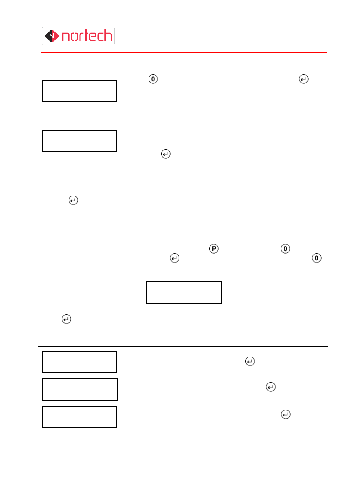
When you first switch the unit on it will display the product code and the version number:
C R C 2 0 0 R V x . x x
N o d e : N
Note: The Node information is only displayed on initial power-up.
Key:
CRC200R = Product Code
Vx.xx = version number
Node: N - indicates the node identity when the CRC200R is
part of a network. For stand-alone operation, this can be
ignored.
P 0
Keys P, 0 and enter ( )
are used to navigate the
menus and enter data:
P - enter/leave
programming mode
0 - step through menus
and values
- select/enter
This display is referred to as the ‘opening display’ and is the starting point for each procedure
described in this guide. The screen will revert back to the opening display after 30 seconds of
inactivity (30 seconds since last key was pressed).
4-1
Page 14

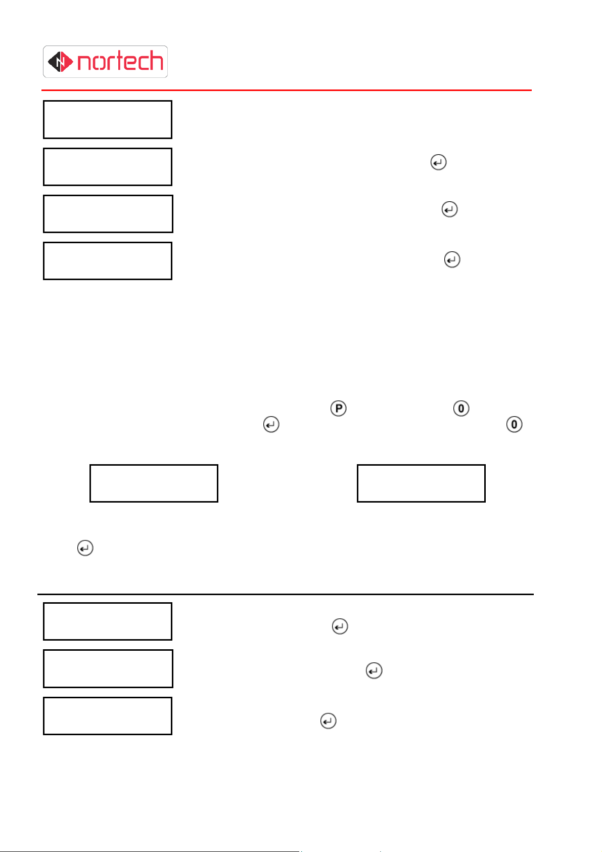
Press (program) to enter the programming mode. The display will show the first menu item.
Press
(enter) while that item is displayed on the screen. The first parameter of that item will then be
displayed in the bottom row of the screen (unless you move to a sub menu).
To enter or change a parameter, type the new value (or use
(enter) to confirm the change. The unit will then move to the next parameter.
On entering the final parameter of a menu item, the unit will automatically move either to the next
menu item or back to the beginning of the current menu item depending upon the particular item.
When you reach the last menu item, a further press of
again.
To go back to the opening display, press
upon where you are in the menu structure).
The structure of the CRC200R menu system is illustrated in Appendix A.
to cycle through the menu items. To enter a particular menu item, simply press
CRC200R USER GUIDE ISSUE 02
to step through options) and press
will take you back to the first menu item
repeatedly until it is shown (up to 3 times depending
4.2 Main Installation Parameters
These parameters are set using the “Installer” sub-menu and are used to control the way in which
the controller operates.
4.2.1 Date & Time
Although the time and date settings are factory set, it is advisable to check them briefly before
entering specific installation details.
Press
once again to enter the sub-menu, and press
once and then press repeatedly until the ‘Installer’ screen is displayed, press
repeatedly until “Date/time” is displayed. Press
to show the first parameter. Refer to section 5.5.3 for details of this procedure.
4.2.2 Operating Parameter
For these parameters, you will need to have the following information available:
4.2.2.1 Time Zone Requirements
The CRC200R allows 3 modes of operation:
OFF
(offline)
LINE
(online)
210 This mode offers additional time zone options and card access level features while still
This mode is no longer used.
This mode is used when the CRC200R is to be used as part of a managed network.
The basic features are the same as those for offline operation.
allowing 2 programmable time zones for door open applications. This mode may be
used in either standalone CRC200R or as part of a managed network (Norpass2 must
also have the feature enabled)
Where many time zones and access levels are required Mode 210 must be selected before cards
are added to the system (see sub-section 4.2.2.5 below).
4-2
Page 15

4.2.2.2 Reader Settings
The following information is required for each reader:
• The required relay operating time (the period for which the door/barrier is to stay open)
• The maximum time that a door can be held open before raising an alarm (applicable to
access control software only)
• Any time periods when a door/barrier is to be left unlocked/open (see 4.2.2.4 –Door Open
Time Zones)
• Whether anti-timeback is to be active and, if so, the anti-timeback period
Also, for the controller:
• Whether the controller is to be linked to control software
• If the controller is linked to control software, its node identity
When you have these details available, follow the procedure in section 5.5.1 to enter them into the
CRC200R.
4.2.2.3 Card Format
You must determine whether the cards that are to be read are in Clock & Data or Wiegand format.
CRC200R USER GUIDE ISSUE 02
If the format is Clock & Data, the number length and the card number location need to be identified
(refer to Appendix B for further information). For Wiegand format cards, the total number of bits
and the number of start bits, check bits, etc. need to be identified (refer to Appendix B for further
information). A site code is not required for these formats on this reader controller.
For standard 26-bit Wiegand format, there is a special option (W26) that avoids the need to enter
the details of the format. Here, the standard site code and card number lengths are adhered to.
Follow the procedure in section 5.5.5 to enter the card format parameters.
Note:
4.2.2.4 Door Open Time Zones
Should any doors or barriers be left unlocked/open at specific times of the day on certain days of
the week?
The use of Door Open Time Zones enables doors to be set to be unlocked during specific times of
the day on certain days and controlled by a reader at all other times.
In addition to the two default time zones (0=always inactive, 1=always active), there are 2
programmable time zones (2 & 3). Any of the 4 time zones may be assigned to a doors/barrier
such that it may be open when the time zone is active and controlled by the reader when the time
zone is inactive.
A useful feature to help identify the card format is provided by the ‘Card Test’ menu item.
This will check the format of a card presented to reader1 and display the format type,
number of digits/bits and the actual number on the card.
Follow the procedure in section 5.5.6 to check a card format.
Each of the two programmable time zones (2 &3) allow up to two active periods per day. Each of
these active periods can also be programmed to be active on specific days of the week.
4.2.2.5 Card Validity Time Zones
Are any of the cards to be valid only at specific times of the day on certain days of the week, or
valid on only one reader?
4-3
Page 16

The CRC200R can support both simple and extended access control requirements for different
types of card relating to the following factors:
Valid reader(s)
Valid times of the day
Valid days of the week
In ‘Line’ mode, the Time Zones used for door open can also be used for card validity (see 4.2.2.4).
If Mode 210 (extended time zone mode) is used, there are 16 access levels, each of which can be
assigned a different set of validity time zones for each reader. There are 15 programmable time
zones available in addition to two fixed time zones (0 = never valid, 1 = always valid). Several time
zones can apply to the same access level, therefore allowing very complex validity period tables to
be set up. The diagram shows the relationship between cards, access levels and time zones.
CRC200R USER GUIDE ISSUE 02
In this example, the card is assigned to access level 2. For this access level, the card is valid on
reader 1 for those times of day/days of the week set up in time zone 1, and is valid on reader 2 for
those times of day/days of week set up in time zones 2 and 4 (where more than one time zone is
assigned, the card will be valid when any of these time zones are set to valid).
The procedure for setting up access levels and time zones in this mode is:
Choose all likely active time periods (e.g. working hours, morning, afternoon, evening, etc.)
1.
and active days (e.g. weekdays, weekend, etc.) and set up appropriate time zones (see
.section 5.8 for programming procedure).
2.
Choose the access levels for groups of cardholders based on applicable validity time zones
specific to each reader, and add them to the CRC200R (see 5.9 for programming
procedure).
Add cards and assign the appropriate access levels (see section 5.1.2 for programming
3.
procedure).
Note:
4-4
210 mode is the standard factory setting and should be used for new installations where
possible. Line mode can be used if a simpler system is required or if it is already in use on
other controllers.
Page 17

It is important that time zones and access levels are carefully planned and written down before
attempting to add them to the CRC200R.
CRC200R USER GUIDE ISSUE 02
4.2.3 Anti-Passback
If anti-passback is to be required, then it must be activated. Once activated, Anti-passback will
ensure that any card being presented to one of the two readers is made invalid for subsequent use
on that reader until it has been presented to the other reader.
It’s possible to programme the CRC200R to reset anti-passback at up to four times per day. Each
reset will cause the APB record (records of APB card numbers that have been presented to one
reader but not to the other reader) to be deleted, allowing these cards to be valid once more on
both readers. Follow the procedure in section 5.5.2 to programme anti-passback mode.
4.3 Programming the Cards
Once the controller has been configured, it needs to be told which cards to accept and how to
manage them. Cards numbers can be added individually or in batches. The CRC200R needs to
know how to treat each card according to which reader it is presented to. This is set by an Access
Level when the CRC200R is in 210 mode (set to ‘1’ if no time restriction is required). In Line mode,
the card must be assigned a Time Zone for each of the two readers, (set to ‘1’ if no time restriction
is required). Where a motorised card reader is connected to the CRC200R, it can be programmed
to capture the card. Alternatively the card capture output can be used to trigger other external
actions such as capturing video from a security camera on digital video recording equipment
(DVR).
In this version of CRC200, the card numbers are stored against indices. A note should be taken of
each index and associated card number. An example form is provided in Appendix C.
Follow the procedure in section 5.1.1 to programme cards in line mode or section 5.1.2. to
programme cards in 210 mode.
Alternatively, the CRC200R is able to ‘Learn’ card numbers when you present the cards to
Reader 1. Follow the procedure in section 5.2 to add cards using the learning method.
Note:
A ‘Verify Card’ feature is also provided to quickly check the programming of any card. To
verify a card, you must enter the index against which the card has been stored. On entering
an index, you will be presented with the card number and a time zone for each reader
(access level in extended time zone mode).
Follow the procedure in section 5.3 to verify cards.
4.4 Setting PIN Codes
If a keypad or keypad/reader combination is connected to the CRC200R, up to 10 PIN codes can
be stored for checking against user input.
Follow the procedure in section 5.4 to add PIN codes.
4-5
Page 18

Page 19

C a r d s
c a r d s
CRC200R USER GUIDE ISSUE 02
5 PROGRAMMING REFERENCE
This section is a step-by-step reference guide to programming each of the parameters of the
CRC200R. The order in which the procedures are described is based on the menu structure and is
not the order in which the CRC200R should be programmed. Please refer to section 0 for an
explanation of the installation programming procedure.
5.1 Program cards
The procedure to programme cards depends on the mode set in the configuration menu. Ensure
that you follow the procedure appropriate to the mode that you have set the CRC200R to.
5.1.1 Program Cards in Line Mode
To programme cards, at the opening display press once. The following is displayed:
P r o g r a m
N N N N
Where ‘NNNN’ = the number of cards currently in memory.
Press
and carry out the following procedure:
Display Action
P r o g r a m C a r d s
S i t e :
P r o g r a m C a r d s
F r o m :
P r o g r a m C a r d s
T o :
P r o g r a m C a r d s
R d r 1 T Z : 0
P r o g r a m C a r d s
C a p t 1 n o
P r o g r a m C a r d s
R d r 2 T Z : 0
This screen only appears when using W26 format.
not required in other modes. Enter the site code and press
Enter the first card number & press
Enter the last card & press
(Simply press
Enter the Time Zone for reader 1 and press
(see section 4.2.2.5)
Use
cards should be captured at reader 1 and press
Enter the Time Zone for reader 2 and press
(see section 4.2.2.5)
to toggle between ‘Yes’ or ‘No’ to indicate whether these
if only one card is to be added).
.
The site code is
.
.
.
P r o g r a m C a r d s
C a p t 2 n o
5-1
Use
cards should be captured at reader 2 and press
to toggle between ‘Yes’ or ‘No’ to indicate whether these
Page 20

C a r d s
N N N N
c a r d s
The display moves back to the first parameter of Program Cards for the next batch of cards to be
added. Press
to escape from this menu item and press to move the next menu item.
CRC200R USER GUIDE ISSUE 02
5.1.2 Program Cards in 210 Mode
To programme cards, at the opening display press once. The following is displayed:
P r o g r a m
Where ‘NNNN’ = the number of cards currently in memory.
Press
Display Action
P r o g r a m C a r d s
S i t e :
and carry out the following procedure:
This screen only appears when using W26 format.
not required in other modes. Enter the site code and press
The site code is
.
P r o g r a m C a r d s
F r o m :
P r o g r a m C a r d s
T o :
P r o g r a m C a r d s
A c c L e v e l : 0
P r o g r a m C a r d s
C a p t 1 n o
P r o g r a m C a r d s
C a p t 2 n o
The display moves back to the first parameter of Program Cards for the next batch of cards to be
added. Press
to escape from this menu item and press to move the next menu item.
Enter the first card number & press
Enter the last card & press
(Simply press
Enter the Access Level assigned to this (these) cards and
press
Use
cards should be captured at reader 1 and press
Use
cards should be captured at reader 2 and press
. (see section 4.2.2.5)
to toggle between ‘Yes’ or ‘No’ to indicate whether these
to toggle between ‘Yes’ or ‘No’ to indicate whether these
if only one card is to be validated).
.
5.2 Learn Cards
This menu item allows you to add cards to the CRC200R by presenting them to a connected
reader. Ensure that an appropriate reader is connected to the ‘Reader 1’ input of the CRC200R
before starting the procedure. The exact procedure depends on the mode set in the configuration
menu. Ensure that you follow the procedure appropriate to the mode that you have set the
CRC200R to.
5-2
Page 21

C a r d s
CRC200R USER GUIDE ISSUE 02
5.2.1 Learning Cards in Line Mode
This menu item is selected when
To reach this menu item from the initial display, press
the following screen is displayed:
Press
Display Action
L e a r n C a r d s
R d r 1 T Z : 0
L e a r n C a r d s
C a p t 1 n o
and carry out the following procedure:
Enter the Time Zone for reader 1 and press
(see section 4.2.2.5)
Use
cards should be captured at reader 1 and press
is pressed in ‘Program Cards’ and then is pressed once.
once and then press repeatedly until
L e a r n
to toggle between ‘Yes’ or ‘No’ to indicate whether these
.
L e a r n C a r d s
R d r 2 T Z : 0
L e a r n C a r d s
C a p t 2 n o
L e a r n i n g
L e a r n i n g
C : X X X X N N N N N N N N
Enter the Time Zone for reader 2 and press
(see section 4.2.2.5)
Use
cards should be captured at reader 1 and press
This display indicates that CRC200R is waiting for a card to be
presented to reader 1. Present a card to the reader.
Card number NNNNNNNN has been saved against index XXXX.
You can now present further cards to be learnt or press
learning mode.
to toggle between ‘Yes’ or ‘No’ to indicate whether these
.
to escape
5-3
Page 22

C a r d s
C a r d s
CRC200R USER GUIDE ISSUE 02
5.2.2 Learning Cards in 210 Mode
This menu item is selected when
To reach this menu item from the initial display, press
the following screen is displayed:
Press
Display Action
L e a r n C a r d s
A c c L e v e l : 0
L e a r n C a r d s
C a p t 1 n o
and carry out the following procedure:
Enter the Access Level assigned to this (these) cards and
press
Use
cards should be captured at reader 1 and press
is pressed in ‘Program Cards’ and then is pressed once.
once and then press repeatedly until
L e a r n
. (see section 4.2.2.5)
to toggle between ‘Yes’ or ‘No’ to indicate whether these
L e a r n C a r d s
C a p t 2 n o
L e a r n i n g
L e a r n i n g
C : X X X X N N N N N N N N
Use
cards should be captured at reader 1 and press
This display indicates that CRC200R is waiting for a card to be
presented to reader 1. Present a card to the reader.
Card number NNNNNNNN has been saved against index XXXX.
You can now present further cards to be learnt or press
learning mode.
to toggle between ‘Yes’ or ‘No’ to indicate whether these
to escape
5.3 Verify Cards
Cards may be verified by looking up the indices and checking the card numbers stored against
them together with their validity information.
This menu item is selected when
reach this menu item from the initial display, press
following screen is displayed:
Press
and carry out the following procedure:
is pressed in ‘Learn Cards’ and then is pressed once. To
once and then press repeatedly until the
V e r i f y
5-4
Page 23

P I N
C o d e
Display Action
V e r i f y C a r d s
C a r d I d x :
Example Result (Mode 210):
V e r i f y : 0 0 0 1
C : 0 0 0 8 0 0 1
Example Result (Line mode):
V e r i f y : 0 0 0 1
C : 0 0 0 8 0 1
0
CRC200R USER GUIDE ISSUE 02
Type the number of the card index against which the card to be
verified is stored and press
This display indicates that the card stored against Index 0001 is card
number 80 and is assigned Access Level 1 (in Extended Time Zone
operating mode). If capture is activated on either of the readers, this
is indicated by a C1 (capture at reader 1) and/or C2 (capture at
reader 1).
This display indicates that the card stored against Index 0001 is card
number 80 and is set to time zone 1 for reader 1 and time zone 0 for
reader 2.). If capture is activated on either of the readers, this is
indicated by a ‘C’ to the right of the time zone value.
Note 1: In W26 format, the card number is shown as site code and card number separated by a
colon (:).
Continue to press
beginning of the “Verify Cards” menu item, so that you can enter another index number. Press
to escape this menu item followed by
to step through the card numbers incrementally. Press
to move to the next menu item.
to return to the
5.4 Set PIN Code
This menu item enables you to set up to 10 (0 to 9) 4-digit PIN codes for use with a suitable
keypad or keypad/reader combination connected.
This menu item is selected when
To reach this menu item from the initial display, press
the following screen is displayed:
Press
and carry out the following procedure:
is pressed in ‘Verify Cards’ and then is pressed once.
once and then press repeatedly until
S e t
Display Action
S e t P I N C o d e
P i n 0 : x x x x x
S e t P I N C o d e
P i n 1 : x x x x x
5-5
Type in the PIN number for PIN location 0 and press
Type in the PIN number for PIN location 1 and press
Page 24

S e t P I N C o d e
P i n 2 : x x x x x
S e t P I N C o d e
P i n x : x x x x x
CRC200R USER GUIDE ISSUE 02
Type in the PIN number for PIN location 2 and press
The screen will continue to increment up to the maximum PIN value
of 9. Press
press
at any time to escape from this menu item and then
to move to the next menu item.
5.5 Installer
This menu item is used to set up installation options. Non-qualified personnel should not alter any
values within this menu item as this may cause the unit to operate incorrectly.
This menu item is selected when
To reach this menu item from the initial display, press
the following screen is displayed:
is pressed in ‘Set PIN Code’ and then is pressed once.
once and then press repeatedly until
I n s t a l l e r
This menu item leads to a sub-menu of installation set-up procedures.
Press
to move to the first sub-menu item:
5.5.1 Configure
This sub-menu item allows you to set the main operational parameters of the controller and is
automatically selected when
To reach this menu item from the initial display, press
the ‘Installer’ screen is displayed, and press
Press
Display Action
C o n f i g
R e l 1 : x x x >
and carry out the following procedure:
is pressed in ‘Installer’.
once and then press repeatedly until
once again. The following screen will be displayed:
C o n f i g
Line Mode: Set the time for relay 1 in tenths of a second up to 25.5
seconds & then press
210 Mode: Set the time for relay 1 in seconds up to 30 seconds (or
set to ‘0’ for 500ms) & then press
.
.
5-6
Page 25

C o n f i g
D r 1 h l d : x x x >
C o n f i g
D r 1 T Z : x >
C o n f i g
R e l 2 : x x x >
C o n f i g
D r 2 h l d : x x x >
CRC200R USER GUIDE ISSUE 02
Enter up to 3 digits to set the timeout for door 1 hold, and then press
.
This is the time (in seconds) that door 1 can be held open for before
an alarm is raised. This facility can only be used in conjunction with
the Norpass2 software.
Enter a Time Zone number (0 to 3) and press
controls the times at which door 1 is left unlocked (if any).
0 = never, 1 = always, 2 and 3 = programmable
(See section 4.2.2.4 for a detailed explanation)
Line Mode: Set the time for relay 2 in tenths of a second up to 25.5
seconds & then press
210 Mode: Set the time for relay 2 in seconds up to 30 seconds (or
set to ‘0’ for 500ms) & then press
Enter up to 3 digits to set the timeout for door 2 hold, and then press
.
This is the time (in seconds) that door 2 can be held open for before
an alarm is raised This facility can only be used in conjunction with
the Norpass2 software.
.
.
. This parameter
C o n f i g
D r 2 T Z : x >
C o n f i g
O p M o d e O f f
C o n f i g
R d r 1 : C A R D
C o n f i g
R d r 2 : C A R D
Enter a Time Zone number (0 to 3) and press
controls the times at which door 2 is left unlocked (if any).
0 = never, 1 = always, 2 and 3 = programmable
(See section 4.2.2.4 for a detailed explanation)
Press
Off = stand-alone mode (no longer used).
Line = online to control software/memory module (see note 1)
210= extended time zone operating mode (see note 2)
Press
Press
CARD = normally closed, opens on valid card read
UNLOCKED = permanently open
LOCKED = permanently closed (not effected by valid card read)
Press
Press
CARD = normally closed, opens on valid card read
UNLOCKED = permanently open
LOCKED = permanently closed (not effected by valid card read)
Press
to step through operation modes:
when the desired mode is displayed.
to step through reader 1 door control options:
when the desired mode is displayed.
to step through reader 2 door control options:
when the desired mode is displayed.
. This parameter
5-7
Page 26

M o d e
C o n f i g
N o d e : x
C o n f i g
R d r 1 A T B :x x >
C o n f i g
R d r 2 A T B :x x >
C o n f i g
P a s s w o r d O f f
CRC200R USER GUIDE ISSUE 02
Type a number to set the node identity of the unit & press
Applicable only to non-standalone units. Each unit within a chain or
sharing a memory module must be given a unique Node identity
between 0 and 31. (See notes 1 and 2)
Enter the anti-timeback period for reader 1 in minutes (between 1 and
30 minutes) and then press
To disable anti-timeback, set this value to ‘0’.
Enter the anti-timeback period for reader 2 in minutes (between 1 and
30 minutes) and then press
To disable anti-timeback, set this value to ‘0’.
Press
when the desired state is displayed. If set to ‘On’, you will be
prompted for a four-digit number. This number will then have to be
entered whenever programming mode is selected from the opening
display. (See note 3)
to toggle the Password option ‘On’ or ‘Off’ and press
.
.
Once the password parameters have been entered, the next sub-menu item is displayed.
Note 1: With ‘Op Mode’ set to ‘LINE’, the use of the ‘Node’ parameters enables the unit to be
configured to work with dedicated PC software. Each controller on the network must have
a unique node number between 0 and 31.
Note 2: With ‘Op Mode’ set to ‘210’, the use of the ‘Node’ parameters enable the unit to be
configured to work with dedicated PC software. The extended time zone feature of
Norpass2 must be enabled to be compatible with this operating mode. Also, each
controller on the network must have a unique node number starting at 0.
Operating mode ‘210’ can also be used in a standalone CRC200R controller where
standard time zone features are not adequate for the application.
Note 3: If you forget the password, you must reset it as follows:
Remove the cover, disconnect power and short circuit the ‘Free exit’ pin on reader input 2
to the ‘0V common’ pin while you reconnect the power.
5.5.2 Set APB Mode
This sub-menu item allows you to activate anti-passback mode and set the associated parameters.
This sub-menu item is automatically selected when the final parameter of ‘Config’ has been
entered and
To reach this sub-menu item from the initial display, press
until the ‘Installer’ screen is displayed, press
repeatedly until the following screen is displayed:
is pressed.
once and then press repeatedly
once again to enter the sub-menu, and press
S e t A P B
Press
5-8
and carry out the following procedure:
Page 27
Display Action
S e t A P B M o d e
A P B n o
S e t A P B M o d e
A P B H o u r 0 : 2 5
Note 1: When APB is active, anti-passback initialisation takes place when the CRC200R is
powered up. This process may take several seconds to complete depending upon the
number of cards in the memory.
Pressing
after the last APB hour will take you to the next sub-menu item.
CRC200R USER GUIDE ISSUE 02
Use the
you change the state, the unit will take a moment to initialise all cards
to that state. Also if you select ‘no’, the unit will skip to the next submenu option. If you select ‘yes’ then it will continue as follows:
You may then enter an hour in the 24-hour clock (0 to 23). At this
hour every day the Anti-passback will initialise, allowing all cards to
work on all valid readers.
‘0’ = midnight, any number above 23 will disable this ‘APB Hour’.
On pressing
which you can set in the same way.
key to toggle between ‘’yes’ and ‘no’, then press . If
you then have a further three ‘APB Hours’ (1 to 3),
5.5.3 Date/Time
This sub-menu item allows you to adjust the time and date in the unit’s real time clock.
This sub-menu item is automatically selected when the final parameter of ‘APB Mode’ has been
entered.
To reach this sub-menu item from the initial display, press
until the ‘Installer’ screen is displayed, press
repeatedly until the following screen is displayed:
D a t e / T i m e
Press
Display Action
D a t e / T i m e
Y e a r : x x
D a t e / T i m e
M o n t h : x x
and carry out the following procedure:
Enter the year as two digits and press
Enter the month in two-digit format and press
once again to enter the sub-menu, and press
once and then press repeatedly
.
.
D a t e / T i m e
D a t e : x x
5-9
Enter the day of the month as two digits and press
.
Page 28
O p e n T Z
D a t e / T i m e
D a y : x
D a t e / T i m e
H o u r : x x
D a t e / T i m e
M i n : x x
D a t e / T i m e
S e c : x x
On completion of these parameters, the unit will move to the next sub-menu item.
CRC200R USER GUIDE ISSUE 02
Enter a number corresponding to the day of the week, with 1 =
Monday, 2 = Tuesday, etc.
Enter the current hour as two digits and press
Enter the current minute as two digits and press
Enter the current second as two digits and press
.
.
.
5.5.4 Timezones (Door Open Timezones when set to ‘210’)
This sub-menu item allows you add parameters for the programmable Time Zones (2 & 3). Please
refer to section 4.2.2.4 for an explanation of these Time Zones.
This sub-menu item is automatically selected when the final parameter of ‘Time/Date has been
entered.
To reach this sub-menu item from the initial display, press
until the ‘Installer’ screen is displayed, press
repeatedly until the following screen is displayed:
once again to enter the sub-menu, and press
once and then press repeatedly
T i m e z o n e s
Press
Display Action
T i m e z o n e 2 - 0
F H o u r : x x
T i m e z o n e 2 - 0
F M i n : x x
T i m e z o n e 2 - 0
T H o u r : x x
Operating Modes ‘LINE’ and ‘OFF’ Operating Mode ‘210’
and carry out the following procedure:
Enter a 2-digit number for the ‘From Hour’ of the first active period
in Time Zone 2 and press
Enter a 2-digit number for the ‘From Minute’ of the first active
period in Time Zone 2 and press
Enter a 2-digit number for the ‘To Hour’ of the first active period in
Time Zone 2 and press
or
D o o r
.
.
.
5-10
Page 29

F o r m a t
T i m e z o n e 2 - 0
T M i n : x x
T i m e z o n e 2 - 0
M o n : N O
T i m e z o n e 2 - 1
F H o u r : x x
T i m e z o n e 3 - 0
F H o u r : x x
CRC200R USER GUIDE ISSUE 02
Enter a 2-digit number for the ‘To Minute’ of the first active period
in Time Zone 2 and press
Use the
When set to ‘yes’, the active period set above will be active on
that day of the week (Monday in this case).
Repeat this sequence for each day of the week. Ignore ‘Hol’
(holiday) as this is not supported in the current build.
Repeat the above procedure for the second active period of Time
Zone 2. On completion, you will then be given the same set of
parameter options for Time Zone 3:
Repeat the procedure for Time Zone 3.
key to toggle between ‘’yes’ and ‘no’, then press .
.
Upon completion of all Time Zone parameters, the unit will move to the next sub-menu item.
5.5.5 Card Format
This sub-menu item is used to set the format of the card data that will be read to the CRC200R so
that it can identify the card number to check. Please refer to Appendix B for help on identifying the
required data.
This sub-menu item is automatically selected when the final parameter of ‘Timezones’ (or ‘Door
Open TZ’) has been entered.
To reach this sub-menu item from the initial display, press
until the ‘Installer’ screen is displayed, press
repeatedly until the following screen is displayed:
C a r d
Press
Display Action
and carry out one the following two procedures according to the card format.
The CRC200R supports:
once again to enter the sub-menu, and press
once and then press repeatedly
Mag - Clock & Data (ISO/ABA Track 2) displayed as
C a r d F o r m a t
M a g
5-11
Wiegand - Wiegand format (variable)
W26 – Standard 26 bit Wiegand.
Use the
The next set of parameters depend on the chosen format (no
further parameters are required for W26).
key to select the required format and then press
.
Page 30

5.5.5.1 Clock & Data Format
For an example of the values to enter for an ISO card number format, see Appendix B.
Display Action
C a r d F o r m a t
D i g i t s : x x
C a r d F o r m a t
C a r d L e n : x
C a r d F o r m a t
C a r d L o c : x
Upon completion of the setting of these parameters, the unit will display the next sub-menu item.
5.5.5.2 Wiegand Format
For an example of the values to enter for a Wiegand format, see Appendix B.
CRC200R USER GUIDE ISSUE 02
Enter the number of digits on the card and press
Enter the number of digits used to represent the cardholder’s
number and press
Enter the location of the first digit of the cardholder’s number
within the card number (counting from 0) and press
.
.
.
Display Action
C a r d F o r m a t
W . B i t s : x x x
C a r d F o r m a t
W . E v e n : x x x
C a r d F o r m a t
W . O d d : x x x
C a r d F o r m a t
W . S B i t s : x x x
C a r d F o r m a t
W . S L o c : x x x
C a r d F o r m a t
W . C B i t s : x x x
Enter the total number of Wiegand bits and press
Enter the number of even bits and press
Enter the number of odd bits and press
This parameter is not required (site code not used). Press
This parameter is not required (site code not used). Press
Enter the number of bits used to represent the cardholder’s
number and press
.
.
.
.
.
.
C a r d F o r m a t
W . C L o c : x x x
Upon completion of the setting of these parameters, the unit will display the next sub-menu item.
5-12
Enter the location of the first bit of the cardholder’s number within
the bit string (counting from 0) and press
.
Page 31

T e s t
CRC200R USER GUIDE ISSUE 02
5.5.6 Card Test
This sub-menu item is used to read the card data format to ensure that it is compatible with the
unit’s settings and to test cards to confirm the data format on them. The card must be presented to
a reader connected to reader input 1. Please refer to Appendix B for help on interpreting this data.
This sub-menu item is automatically selected when the final parameter of ‘Card Format’ has been
entered.
To reach this sub-menu item from the initial display, press
until the ‘Installer’ screen is displayed, press
repeatedly until the following screen is displayed:
C a r d
Press
The screen will display a code on the top line indicating the format and the number of digits/bits,
and will display the actual number on the second line.
and then present the card to reader 1.
once again to enter the sub-menu, and press
once and then press repeatedly
Examples:
Clock & Data Format
M 1 0
0 0 1 2 3 4 0 0 0 1
Wiegand Format
C a r d T e s t
2 6 0 0 8 A 5 A C 0
Continue to present cards to reader 1 as required.
This is the last item in the ‘Installer’ sub-menu. Press
Note: To get an accurate reading, the reader type (C&D or Wiegand) for the expected card format
should be connected to reader input 1 and the corresponding format setting selected in
CRC200R.
M = ‘Mag stripe’ (Clock & Data), 10 = 10 digit number length.
0012340001 = card number.
26 = 26 bit (Wiegand).
008A5AC0 = bit values represented as a hexadecimal number.
to proceed to the next menu item.
5.6 Clear Cards
This menu is for high level administrators only and must be used with care. When activated, all
card records will be cleared from the CRC200R memory. Prior to using this feature, ensure that
‘Password Protection’ has been activated and a 4-digit password has been set (see section 5.5.1).
Even if ‘Password Protection’ is no longer active, the latest password set can be used for clearing
cards.
To reach this menu item from the initial display, press
the following screen is displayed:
5-13
once and then press repeatedly until
Page 32

C a r d s
Press
C l e a r C a r d s
P a s s w o r d ?
C l e a r C a r d s
C a r d s C l e a r e d
and carry out the following procedure:
CRC200R USER GUIDE ISSUE 02
C l e a r
Enter the 4-digit password and press
WARNING:
press ‘return’.
The ‘Cards Cleared’ message is shown momentarily. Press
move on to the next menu item.
All cards will be deleted from memory when you
.
5.7 Clear Events
The ‘Clear Event’ menu item is for support staff only and should be ignored by normal users.
to
5-14
Page 33

T i m e z o n e s
CRC200R USER GUIDE ISSUE 02
5.8 Timezones (Available only in Mode ‘210’)
This menu item is used for setting up the extended time zone features when in operating mode
‘210’. It is used in conjunction with ‘Access Levels’ (see section 5.9).
To reach this menu item from the initial display, press
the following screen is displayed:
Press
Display Action
T i m e z o n e s
T i m e z o n e : ?
and carry out the following procedure:
Enter a one or two digit number between 2 and 16 to select the
time zone that you wish to set and press
once and then press repeatedly until
.
T i m e z o n e N N
F H o u r : x x
T i m e z o n e N N
F M i n : x x
T i m e z o n e N N
T H o u r : x x
T i m e z o n e N N
T M i n : x x
T i m e z o n e N N
M o n : N O
T i m e z o n e s
T i m e z o n e : ?
Enter a 2-digit number for the ‘From Hour’ of the active period in
Time Zone NN and press
Enter a 2-digit number for the ‘From Minute’ of the active period in
Time Zone NN and press
Enter a 2-digit number for the ‘To Hour’ of the active period in
Time Zone NN and press
Enter a 2-digit number for the ‘To Minute’ of the active period in
Time Zone NN and press
Use the
When set to ‘yes’, the active period set above will be active on
that day of the week (Monday in this case).
Repeat this sequence for each day of the week. Ignore ‘Hol’
(holiday) as this is not supported in the current build.
Once the time zone has been programmed, the next time zone
can be chosen and the above sequence repeated.
key to toggle between ‘’yes’ and ‘no’, then press
.
.
.
.
.
To escape from this menu, press
5-15
once and use the key to step to other menu items.
Page 34

L e v e l s
CRC200R USER GUIDE ISSUE 02
5.9 Access Levels (Available only in Mode ‘210’)
This menu item is used for setting up the extended time zone features when in operating mode
‘210’. It is used in conjunction with ‘Timezones’ (see section 5.8).
This menu item is selected when
reach this menu item from the initial display, press
following screen is displayed:
Press
Display Action
A c c e s s L e v e l s
L e v e l : ?
and carry out the following procedure:
is pressed in ‘Timezones’ and then is pressed once. To
once and then press repeatedly until the
A c c e s s
Enter a one or two digit number between 0 and 15 to select the
access level that you wish to set and press
.
A c c L e v e l N N
R d r 1 : T Z 1 : N O
A c c L e v e l N N
R d r 1 : T Z 2 : N O
A c c L e v e l N N
R d r 2 : T Z 1 : N O
A c c e s s L e v e l s
L e v e l : ?
To escape from this menu, press
Use the
When set to ‘yes’, time zone 1 will be active for access level NN
Repeat the sequence for each time zone for reader 1. After the
last time zone (time zone 16) the display will change to show time
zones for reader 2
Follow the same procedure as for reader 1 to set the time zones
for reader 2.
Once the access level has been programmed, the next access
level can be chosen and the above sequence repeated.
once and use the
key to toggle between ‘’yes’ and ‘no’, then press
key to step to other menu items.
.
5-16
Page 35

CRC200R USER GUIDE ISSUE 02
6 CRC200R COMMUNICATIONS
The CRC200R can be used in one of two modes:
• Stand-alone
• Online to a PC running Norpass2 Access Control Software.
6.1 Online to Norpass2
For real time output of card transactions or to enable the controller to be controlled via the software
the CRC200R must be connected to a PC via the USB to RS485 converter provided. See the on
screen help of the software for more information about the RS485 interface. Using the ‘Config’
menu in the CRC200R, configure each controller with a unique node identity (starting at ‘0’) and
set it to ‘ONLINE’ mode. Also see software on-screen help.
6.1.1 RS485 Connector and Protocol Selection link
To connect to Norpass2, the USB to RS485 converter supplied with Norpass2 must be wired the
RS485 connector of each CRC200 controller that it is to control. The jumper just below the RS232
connector at the side of the controller must be set to RS485 (bottom two pins), and the cable
terminated at the RS485 connector block (see below). Refer to Norpass2 online help for more
details on wiring the RS485 bus.
.
GND
RS232
LINK SET TO
RS485
Tx
Rx
5v
D+
D-
GND
RS485
6-1
Page 36

Page 37

CRC200R USER GUIDE ISSUE 02
7 TECHNICAL SPECIFICATIONS
Description: Two channel card reader controller.
Card capacity: Up to 10,000 non-sequential cards on one controller
Suitable readers: Nortech DualProx range, Nortech EM2100 proximity range, RH301
magnetic stripe, RH320 magnetic stripe/keypad combined, ASR603
proximity, MRC310 card capture reader and Hyper X long-range
readers. Any industry standard reader giving Clock & Data or Wiegand
output.
Dimensions: 160mm x 120mm x 30mm.
Weight: 300 grams.
Supply voltage: 12 to 24 volts DC
If the reader voltage link is set to ‘12V’ it connects the supply
voltage directly to the reader. Therefore, if a 12V DC reader is
used then the supply voltage needs to be 12V DC. If in doubt
always measure the reader voltage before connecting the reader.
Please see note in section 3.2.1
Termination:
Display: LCD, 2 lines x 16 characters.
Controls: 12 button membrane keypad, 0 - 9, Program, Enter.
Request to exit: 2 independent inputs operating latch relays.
Latches: 2 independent voltage free changeover relays (2A, 30V DC)
Arming: 2 arming inputs (doubled with door monitoring inputs)
Auxiliary Outputs: 2 open collector outputs for card capture, DVC control, etc.
Current requirement: 100 mA quiescent, up to 500mA while reading at both readers
Pluggable screw terminal strip.
simultaneously (depending upon types of readers).
7-1
Page 38

Page 39

CRC200R USER GUIDE ISSUE 02
Appendix A – Menu Structures
Operating Mode
P
Program Cards
Learn Cards
Verify Cards
P
0
0
0
0
Set PIN Codes
0
Installer
0
Clear Cards
0
Clear Events
0
Time Zones
0
Access Levels
0
Config
P
SetAPB Mode
Date/Time
Door Open TZ
Card Format
Card test
0
0
0
0
0
0
210 Mode
Press
Press
A-1
to enter a menu item
to escape a menu item or move up a level
Page 40

CRC200R USER GUIDE ISSUE 02
Operating Mode
P
Program Cards
0
Learn Cards
Verify Cards
Set PIN Codes
0
0
0
P
0
Installer
0
Clear Cards
0
Clear Events
0
Config
P
Set APB Mode
Date/Time
Timezones
Card Format
Card test
0
0
0
0
0
0
Line Mode
Press
Press
to enter a menu item
to escape a menu item or move up a level
A-2
Page 41

CRC200R USER GUIDE ISSUE 02
Appendix B – Card Formats
Clock & Data (ISO/ABA Track 2)
This is an example of card format parameters for an ISO card to be entered in the ‘Card Format’
menu item. The card number is 0012340001 and the lowest 8 digits need to be read .
Digit No. 0 1 2 3 4 5 6 7 8 9
Value 0 0 1 2 3 4 0 0 0 1
You would set it up as follows: Digits: 10
Card Len: 8
Card Loc: 2
Wiegand
This is an example of card format parameters for Wiegand card using a standard 26-bit format.
The structures for other Wiegand formats are more complex and may not be possible to decode.
CARD NUMBER
As no site code is necessary, you can use any number of available 24 bits (excluding the parity
bits) to form the card number. The most significant bit is determined by the ‘Card Loc’ parameter
and the number of bits used is determined by ‘Card Bits’.
When ‘Card Test’ is performed, the information on the card is displayed on the screen in
hexadecimal form.
The conversion from an example hexadecimal reading of 008A5AC to a binary frame structure is
shown below.
Use a scientific calculator (available on MS windows) to convert from Hex to binary:
0 0 8 A 5 A C
0 1 2 3 4 5 6 7 8 9 10 11 12 13 14 15 16 17 18 19 20 21 22 23 24 25
0 0 0 0 0 0 0 0 1 0 0 0 1 0 1 0 0 1 0 1 1 0 1 0 1 1 0 0
P CARD NUMBER = 70837 P
Enter the bits to be used in the card number (00010001010010110101 in this example) into a
scientific calculator in binary mode and convert it to decimal.
The settings for the CRC200R would be as follows:Number of Bits: 26
Wiegand Even Bits: 13
Wiegand Odd Bits: 13
Wiegand Card Bits: 20
Wiegand Card Loc: 5
If you are in any doubt about the format of the cards that you wish to use, contact Nortech’s
technical support team, who would be happy to help you identify the appropriate parameters.
B-1
Page 42

Page 43

CRC200R USER GUIDE ISSUE 02
Appendix C – Card Record Sheet
Index Card No.
Date
Issued
Cardholder
Date
Returned
Note
(Lost, Stolen)
C-1
 Loading...