

Nortec GS 100, GS 200, GS 300, GS 400, GS 500 Maintenance Manual
...
GS Series
Gas Steam Humidifier
Installation,
User & Maintenance
Guide
IMPORTANT: Read and save this guide for future reference. This
guide to be left with equipment owner.
Form #07-287
150-6222
FOR YOUR SAFETY:
Do not store or use gasoline or other flammable vapors and liquids in
the vicinity of this or any other appliance.
WHAT TO DO IF YOU SMELL GAS:
Do not try to light any appliance.
Do not touch any electrical switch; do not use any telephone in your
building.
Immediately call your gas supplier from a neighbor’s telephone.
Follow the gas supplier’s instructions. If you can not reach your gas
supplier, call the fire department.
UNIT OPERATING RANGES:
Max. Ambient Temperature 104ºF (40ºC).
Min. Ambient Temperature 41ºF (5ºC).
Max. Relative Humidity (RH) non-condensing 95% RH.
Min. Relative Humidity (RH) non-condensing 5% RH.
WARNING:
Improper installation, adjustment, alteration, service or maintenance
can cause injury or property damage. Refer to this manual. For
assistance or additional information consult a qualified installer, service
agency, or the gas supplier.
WARNING:
If the information in this manual is not followed exactly, a fire or
explosion may result causing property damage, personal injury or loss
of life.
IMPORTANT:
Read and save this guide for future reference. This guide to be left with
equipment owner.

Table Of Contents
GENERAL 1
- WARNING ................................................1
- DELIVERY ................................................1
- RECEIVING & UNPACKING EQUIPMENT................................1
- GENERAL SPECIFICATIONS ......................................1
- MODEL DESIGNATION .........................................1
MODEL SPECIFICATION 2
GS INDOOR INSTALLATION 3
- LOCATING AND MOUNTING ......................................4
- GAS PIPING ...............................................5
- COMBUSTION AIR REQUIREMENTS ..................................6
- DIRECT VENT GUIDELINES.......................................6
- EXHAUST VENTING ...........................................7
- ADDITIONAL REQUIREMENTS WHEN VENTING THROUGH A SIDEWALL .............11
- ELECTRICAL ..............................................12
- PRIMARY WIRING ...........................................13
- LOW VOLTAGE CONTROL WIRING .................................14
- CONTROL INSTALLATION .......................................15
- PLUMBING ...............................................15
- FILL WATER SUPPLY LINE ......................................15
- DRAIN LINE ...............................................15
- AUX DRAIN PORT ...........................................16
-STEAM LINES AND CONDENSATE LINE ...............................16
GS OUTDOOR INSTALLATION 16
- MOUNTING ...............................................16
-TYPICAL GSTC OUTDOOR INSTALLATION ..............................17
- ROOF CURB DIMENSIONS ......................................18
- GAS PIPING...............................................19
- EXHAUST VENTING ..........................................20
- ELECTRICAL INSTALLATION .....................................20
- FILL WATER SUPPLY LINE ......................................21
- DRAIN LINE ...............................................21
- AUXILIARY DRAIN ...........................................21
- STEAM LINES..............................................22

PRINCIPLE OF OPERATION 22
- COMBUSTION .............................................22
- WATER MANAGEMENT ........................................22
- START UP PROCEDURE .......................................23
- FILLING THE SYSTEM .........................................23
- TESTING THE IGNITION SAFETY SHUT-OFF.............................23
- STARTING THE HUMIDIFIER .....................................24
- TAKING OUT OF OPERATION .....................................24
- INSTALLATION CHECKLIST ......................................25
- SCALE MANAGEMENT .........................................27
- WATER QUALITY ............................................27
- FAULT CONDITIONS ..........................................28
MAINTENANCE 28
- DRAINING THE TANK .........................................28
- MANDATORY MAINTENANCE SCHEDULE ..............................29
- CLEANING THE TANK .........................................30
- SERVICING THE UNIT .........................................31
- SERVICE CHECKS ...........................................31
- COMPONENTS REPLACEMENT....................................32
-Hot Surface Igniter and Flame Sensor Replacement ........................32
-Burner Removal and Installation ...................................32
-Removal and Installation of the Combustion Blower.........................33
-Gas Valve Replacement .......................................33
-Air Switch Replacement .......................................34
-Float Chamber Replacement ....................................34
-Transformer Replacement ......................................35
-Fill Valve Replacement .......................................35
-Drain Pump Replacement ......................................36
-Fill Box Replacement ........................................36
-Removal of the Heat Exchanger ...................................37
- DIP SWITCH SETTINGS ........................................38
- SOFTWARE FLOW CHART ......................................39
- FAULT AND WARNING LIST ......................................60
- EXPLODED VIEW INTERNAL COMPONENTS SPARE PARTS ....................63
- EXPLODED VIEW INDOOR CABINETRY SPARE PARTS.......................65
- EXPLODED VIEW OUTDOOR CABINETRY SPARE PARTS .....................67
- GS QUICK REFERENCE ........................................71
GENERAL
N
C
This installation guide has been designed to
provide assistance when installing, mounting, and
commissioning a GS Series humidifier. Actual on site
application may vary. Consult Technical Services or
your local NORTEC representative.
WARNING
Improper installation, adjustment, alteration,
·
service, maintenance, or use can cause carbon
monoxide poisoning, an explosion, fire, electrical
shock, or other conditions which may cause
personal injury or property damage. Consult a
qualified installer, service agency, local gas
supplier, or your distributor or branch for
information or assistance. The qualified installer
or agency must use only factory authorized and
listed kits or accessories when modifying this
product. A failure to follow this warning can
cause electrical shock, fire, personal injury, or
death.
· Should overheating occur, or the gas fail to shut
off, shut off the manual gas valve to the appliance
before shutting off the electrical supply.
· Do not use this appliance if any part has been
under water. Immediately call a qualified service
technician to inspect the appliance and to replace
any part of the control system and any gas
control which has been under water.
DELIVERY
The standard delivery includes:
RECEIVING & UNPACKING EQUIPMENT
Check packing slip to ensure ALL material has
·
been delivered.
All material shortages are to be reported to
·
NORTEC within 48 hours from receipt of goods.
NORTEC assumes no responsibility for any
material shortages beyond this period.
Inspect shipping boxes for damage and note on
·
shipping waybill accordingly.
After unpacking, inspect equipment for damage
·
and if damage is found, notify the shipper
promptly.
All NORTEC products are shipped on an F.O.B.
·
factory basis. Any and all damage, breakage or
loss claims are to be made directly to the
shipping company.
GENERAL SPECIFICATIONS
The NORTEC GS Series humidifier is a
completely new patented design based on leading
edge technology. The GS is designed to provide clean
steam humidification at an economical price.
The GS Series humidifiers are designed
exclusively for humidification in ventilation systems or
direct room humidification. Any other type of
application, without the written consent of Nortec or
your Nortec agent, is considered as not conforming
with the intended purposes. The manufacturer/
supplier can not be made liable for any damages
resulting from improper use.
·
Gas Steam humidifier equipped with desired
options.
·
In a bag you will find:
- Manuals.
- Adapter fittings for water connection.
- Steamhose for steam outlet with clamps.
- Hose and clamps for drain connection.
·
The GS Indoor Series offers an optional
telescopic stand mounted inside the unit legs.
Stand cross bracing are shipped with the unit.
·
The GS Outdoor Series comes with all required
venting to be installed on site.
·
Desired accessories ordered.
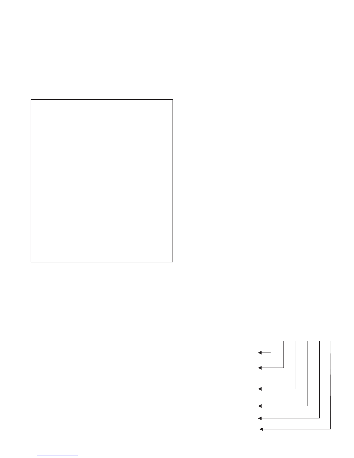
MODEL DESIGNATION
The unit specification label indicates the model of
gas humidifier according to the following chart:
GS 100 N DV
TC
PRODUCT LINE
(Gas Steam Humidifier)
TC = Total Controller
c/w KEYPAD
P = Economical
Humidifier size (lbs/hr)
FUEL
= NATURAL GAS
P = PROPANE GAS
DIRECT VENT
OPTION
OUTDOOR MODEL
100
200
300
400
500
600
-1-
O
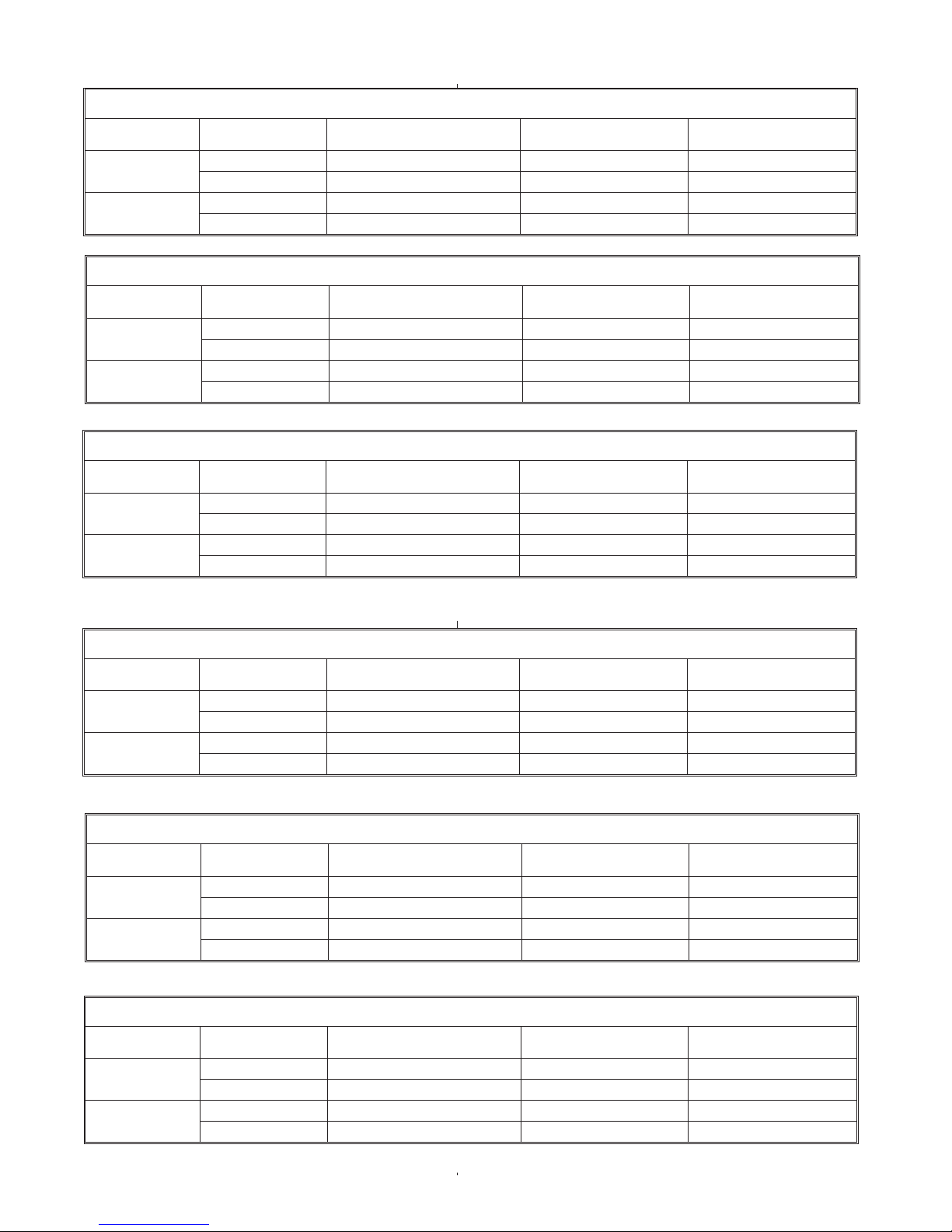
MODEL SPECIFICATION
MODEL GS 100 SPECIFICATIONS
FUEL BLOWER SPEED INPUT (BTUH)* STEAM CAPACITY (LBS/HR) MANIFOLD PRESS. IN W.C.
NATURAL GAS MAX 140,000 105 -0.05
MIN 45,000 25 -0.05
PROPANE MAX 140,000 105 -0.35
MIN 50,000 25 -0.35
MODEL GS 200 SPECIFICATIONS
FUEL BLOWER SPEED INPUT (BTUH)* STEAM CAPACITY (LBS/HR) MANIFOLD PRESS. IN W.C.
NATURAL GAS MAX 280,000 210 -0.05
MIN 45,000 25 -0.05
PROPANE MAX 280,000 210 -0.35
MIN 50,000 25 -0.35
MODEL GS 300 SPECIFICATIONS
FUEL BLOWER SPEED INPUT (BTUH)* STEAM CAPACITY (LBS/HR) MANIFOLD PRESS. IN W.C.
NATURAL GAS MAX 420,000 315 -0.05
MIN 45,000 25 -0.05
PROPANE MAX 420,000 315 -0.35
MIN 50,000 25 -0.35
MODEL GS 400 SPECIFICATIONS
FUEL BLOWER SPEED INPUT (BTUH)* STEAM CAPACITY (LBS/HR) MANIFOLD PRESS. IN W.C.
NATURAL GAS MAX 560,000 420 -0.05
MIN 45,000 25 -0.05
PROPANE MAX 560,000 420 -0.35
MIN 50,000 25 -0.35
MODEL GS 500 SPECIFICATIONS
FUEL BLOWER SPEED INPUT (BTUH)* STEAM CAPACITY (LBS/HR) MANIFOLD PRESS. IN W.C.
NATURAL GAS MAX 700,000 525 -0.05
MIN 45,000 25 -0.05
PROPANE MAX 700,000 525 -0.35
MIN 50,000 25 -0.35
FUEL BLOWER SPEED INPUT (BTUH)* STEAM CAPACITY (LBS/HR) MANIFOLD PRESS. IN W.C.
NATURAL GAS MAX 840,000 630 -0.05
MIN 45,000 25 -0.05
PROPANE MAX 840,000 630 -0.35
MIN 50,000 25 -0.35
MODEL GS 600 SPECIFICATIONS
-2-
l
HIGH ALTITUDE
- A derate in input exists for installations at higher altitudes. For Canadian models, an automatic
10% derate applies to installations from 2000-4500 feet. For U.S. Models, refer to the chart below for high altitude
derate information.
FOR U.S. MODELS ONLY
Altitude Derate %
Feet Meters
0-2000 0-610 0
2001-3000 610-915 8
3001-4000 915-1220 12
4001-4500 1220-1370 16
4501-higher 1370-higher Contact Factory
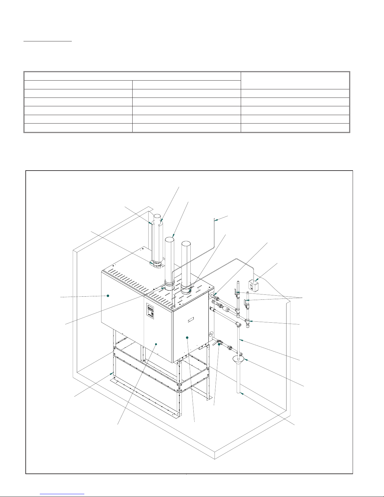
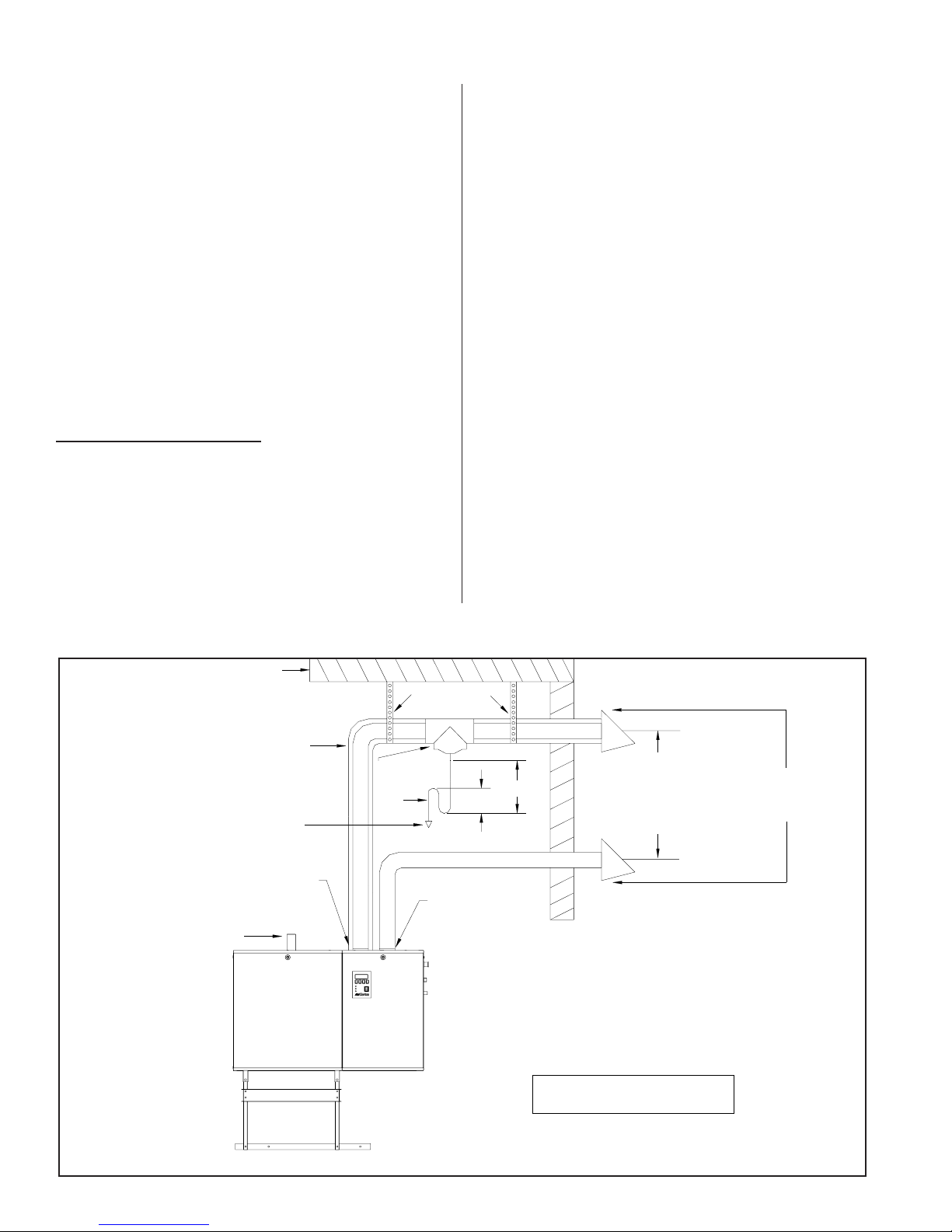
Figure #1
Typical Installation (Indoor)
Steamline
Clean Out
Access Door
Exhaust Outlet
Snap on Installation
Steam Outlet
B or BH Venting Type
Control Wiring
Optional
Direct Vent
Gas Line
Connection
Main Power Disconnect
Shut Off
Fresh Water
Fill Line
3/4"min 30-80 psi
Drain
Optional Stand
Service Access
Door (Electrical)
Service Access Door
(Mechanical)
-3-
Air Gap with Funne
Auxiliary Drain
To Drain
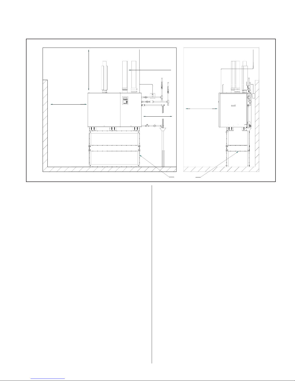
Figure #2
Clearance Requirements
Minimum
36" (91.5 cm)
Left
36" (91.5 cm)
Required only for
GSTC/GSP
500/600
Side Clearance
Minimum
4" (10.2 cm) to vent pipe
Right
30" (76.2 cm)
Optional Stand
Front Clearance
Front
30" (76.2 cm)
INDOOR INSTALLATION
The installation must conform with local building
codes or, in the absence of local codes, with the ANSI
Z223.1, National Fuel Gas Code, and/or CAN/CGA
B149 Installation Codes. Refer to the Gas Piping
section of this manual.
LOCATING AND MOUNTING
GS Series humidifiers are designed for floor
mounting or on a GS Stand (optional). The clearance
dimensions shown in this manual are for reference
only and are the minimum required for maintenance of
the humidifier. Local and National Codes should be
consulted prior to final location and installation of the
humidifier. NORTEC cannot accept responsibility for
installation code violations.
Figure #1 shows a typical installation with all
required connections to the GS Humidifier. Careful
consideration should be given to all of these
connections when choosing a location for the
humidifier.
· Ambient temperature location for humidifier:
41ºF - 104ºF (5ºC - 40ºC).
· Relative humidity location for humidifiers:
5% rh - 80% rh.
·
All GS humidifiers are rated for the clearance to
shown in Figure #2.
·
Location of the steam distributor should be
minimum of 36” above the humidifier.
·
DO NOT locate humidifier any further than
absolutely necessary from steam distributor
location. Net output will be reduced as a result of
heat loss through steam line. Also, increased
static pressure (over 12" W.C.) will result in hot
water going down the drain. Consult factory if this
situation occurs.
·
Where possible, mount humidifier at a height
convenient for servicing.
·
Make sure the humidifier is mounted level.
WARNING: During installation cover the
humidifier to prevent any dust or other
contaminants from entering the cabinets when
activities such as drilling are taking place.
-4-
·
DO NOT mount humidifier on hot surfaces.
·
The humidifier must be installed so that all
electrical components are protected from
exposure to water.
DO NOT mount humidifiers in an area where
·
freezing may occur.
If humidifiers are mounted on a roof, a properly
·
ventilated, temperature controlled, (above
freezing), weatherproof enclosure must be used.
DO NOT mount humidifiers on vibrating surface.
·
Consult factory.
The humidifier shall not be installed directly on
·
carpeting, tile or other combustible material other
than wood flooring.
The gas inlet pipe size to the appliance is:
½” NPT for GS 100
¾” NPT for GS 200
1” NPT for GS 300 / 400
1 ¼” NPT for GS 500 / 600
Provide an adequate size gas supply line.
In all installations, a certified manual shut off
valve, located outside the cabinet, must be installed.
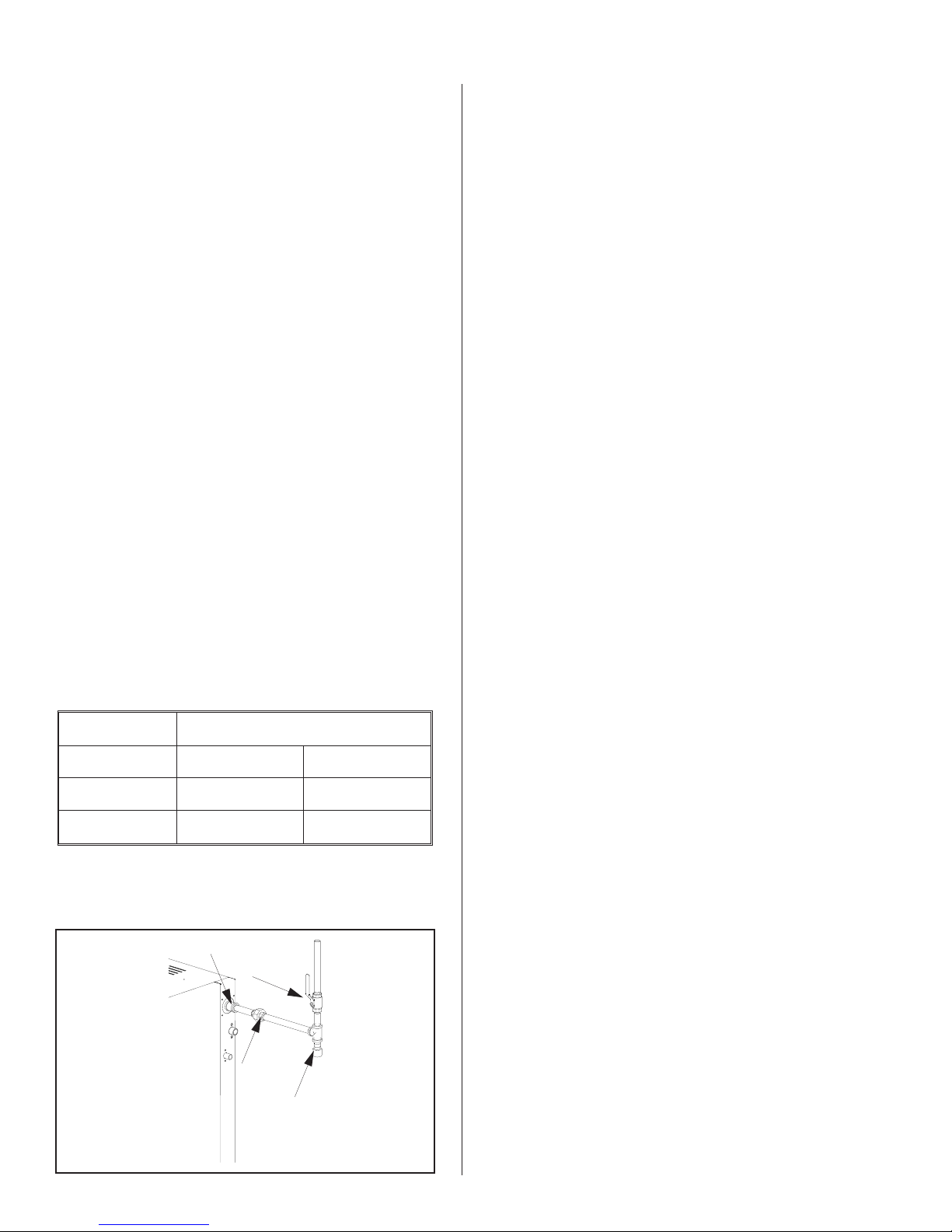
When black iron gas pipe is used, a sediment trap
must be located ahead of the humidifier gas controls.
See Figure #3.
Some insulating materials may be combustible.
·
Prior to installing this appliance examine the area
for insulating material. If this appliance is
installed in an insulated space, it must be kept
free and clear of insulating materials. If insulation
is added after the appliance is installed, it will be
necessary to examine the area again.
GAS PIPING
Installation of piping must be in accordance with
local codes, and ANSI Z233.1, “National Fuel Gas
Code,” in the United States or CAN/CGA-B149
Installation Codes in Canada.
The following table indicates the maximum and
minimum allowable gas pressures for the Gas
Humidifier.
INCHES W.C.
GAS MIN. MAX.
Natural 4.5 9.0
Leak test all gas connections external to the
humidifier, using a commercial soap solution made to
detect leaks. Bubbles indicate gas leakage. Seal all
leaks before placing the humidifier in operation.
WARNING: Never use an open flame to check for
gas leaks. If a leak does exist, a fire or explosion
could occur, resulting in damage, injury or death.
The appliance must be isolated from the gas
supply piping system by closing its individual manual
shut-off valve during any pressure testing of the gas
supply piping system at test pressures equal to or
greater than 14” w.c. (3.5 kPa).
Dissipate test pressure from the gas supply line
before re-opening the manual shut off valve to the
appliance.
NOTES: (See pg 19 for additional Gas Piping
information)
·
Failure to follow this procedure may damage the
gas valve. Over pressured gas valves are not
covered by warranty.
Propane 9.0 13.0
Figure #3
Gas Connection
Inlet coupling supplied
Shut-off Gas Valve
(by others)
Union
(by others)
Sediment Trap
(by others)
·
DO NOT use Teflon tape on gas line pipe
threads. A flexible sealant suitable for use with
Natural Gas and Propane Gas is recommended.
·
Plan gas supply piping so it will not interfere with
removal of gas valves or blower assemblies and
front or side service doors.
·
All gas piping should be adequately supported to
prevent any strain on inlet piping.
The gas valve is provided with pressure taps to
measure gas pressure upstream and downstream,
(manifold pressure). The minimum gas pressure
shown is for the purpose of input adjustment.
A 1/8" NPT plugged tapping, accessible for test
gage connection, must be installed immediately
-5-
upstream of the gas supply connection to the
appliance.
recommended that the supply air line is insulated and
an in line heat is added. Consult factory.
COMBUSTION AIR REQUIREMENTS
Provide for adequate combustion and ventilation
air in accordance with Sections 8.3, Air for Combustion
and Ventilation, of the National Fuel Gas Code, ANSI
Z223.1, or Sections 7.2, 7.3, 7.4 of CAN/CGA B149
Installation Codes, or applicable provisions of the local
building codes.
The required free area of supply air opening is:
13 in. sq. (8,387 mm
23 in. sq. (14,839 mm
35 in. Sq. (22,581 mm
47 in. Sq. (30,323 mm
59 in. Sq. (38,064 mm
71 in. Sq. ( 45,806 mm
Cabinet top and bottom contain air openings to
provide combustion air to the forced draft blower. DO
NOT BLOCK THESE OPENINGS.
Excessive exposure to contaminated combustion
air will result in safety and performance related
problems. Known contaminates include halogens,
ammonia, and chlorides, excessive dust, lime or dirt.
Excessive exposure of electronics to the contaminants
will also result in performance related problems.
Contact NORTEC Technical Services if you have any
questions. If contaminants exist, isolate the unit from
the contaminated space.
2
), for GS 100
2
), for GS 200
2
), for GS 300
2
), for GS 400
2
), for GS 500
2
), for GS 600
Attach the air supply line to the manifold using a
hose clamp or hose coupling if required. See Figure
#4.
WARNING: Air supply line should not obstruct
any services going to the humidifier front and
right side cabinet panels.
WARNING: BH Type venting must be used in
a direct vent application.
The air intake terminal and the flue gas terminal
must end at an outside location. See Figure #5.
Air Piping Insulated
(by others)
Hose Coupling
(by others)
Air Intake Connection
DIRECT VENT GUIDELINES
Installation of the combustion air supply line must
be carried out by adequately qualified personnel. All
local regulations relating to the provision of air supply
systems must be observed and adhered to.
The maximum pipe length for the air supply line
and exhaust is equivalent to 70’ (21m). The vent pipe
diameter must be maintained over the overall length of
the vent.
All air piping must be listed type for direct vent
application with sealed joints and seams, such as Z
flex.
The air supply line should be approximately as
long as the flue gas venting and must be supported at
every 5 ft. (1.5 m) and additionally at every pipe bend.
The air supply line must be installed with air
supply terminals provided.
At low temperatures, water condensation can form
on the outside of the pipe. To prevent this, it is
Figure #5
Direct Vent Side Wall Requirements
Exhaust terminal with
opening vertical.
Intake terminal with
opening vertical.
4ft-6ft
(1.2 m - 1.83 m)
Keep 6“ (15.2 cm)
away from sidewall.
-6-
Location of air intake and flue gas terminal must
g
comply with all local and national regulations.
EXHAUST VENTING
The GSTC and GSP are classed category I and III
fan assisted gas appliances. This allows two methods
of venting. Listed below are instructions for both
venting systems, followed by specific requirements for
each system.
Review the requirements for both category I and III
installations and select the venting method best suited
for the installation.
Category III class must be used in direct vent
applications.
GENERAL REQUIREMENTS
The vent systems shall be listed to UL or UL/CSA
·
standard and meet the installation requirements
of the National Fuel code in the USA ( ANSI
Z223.1) and the Canadian Standards
CAN/CGA.B149 Installation Codes. Any local
jurisdictions reflecting changes to the above
codes should be observed.
In applying the codes, reference should be given
·
to the venting manufactures instructions, the
serving gas supplier regulations, and the specific
instructions provided in this manual.
This appliance must be installed to comply with
·
national regulations and codes. A qualified
technician, competent with these codes and the
local requirements of the jurisdiction must carry
out the installation.
Proper removal of combustion gases must be
·
assured, and building materials must be
protected from degradation by flue gases.
Never mix venting types. (B to BH or visa versa.)
·
Never use two different manufacturer’s
equipment for the same chimney.
All vent runs should be as direct as possible with
·
no more than 6 elbows in the system.
Maintain an upward slope of ¼” per ft on all
·
horizontal vent pipe runs.
· This gas humidifier may not be used in
conjunction with a power venter or draft inducer.
Horizontal Venting Using a Direct Vent Application Using BH Type Only
Wall
BH type vent using double wall vent
with all joints being air and water tight.
Reference local and/or national codes
before installation of the vent
Condensate tee and trap must
be installed. Take the condensate
to a floor drain or a condensate pump
Exhaust venting outlet
Steam
Outlet
Hangers straps
Condensate
Tee
Trap
Figure #6
3” Min
Direct vent
Inlet
2ftMin
Exhaust venting must
be min.4 ft, max.6 ft
in distance apart from
the fresh air intake
for direct venting
Terminations
supplied with
unit
Note: These are
BH type double wall with double
wall connectors required.
uidelines only. Follow the local and/or national codes inyour respective area.
-7-

Figure #7
Vertical Venting Application Using B or BH Venting
UL Listed Cap
Required
Flashing
B or BH type vent using double wall vent
with double wall connectors is required.
Reference local and/or national codes
before installation of the vent.
Horizontal run
1/4"rise per ft
4" minimum air
space required
Exhaust venting
outlet
Steam Outlet
Side Wall Venting Application Using BH Type Only
Wall
BH type vent using double wall vent
with all joints being air and water tight.
Reference local and/ or national
codes before installing vent
Trap
3” Min.
Condensate tee and
trap must be installed.
Take the condensate to
a floor drain or a
condensate pump.
Figure # 8
Hangers Straps
Condensate tee
required
2 FT Min
B type double wall vent with
double wall connectors required
for category I appliances.
Limitations on horizontal
distance when venting with B
vent
BH type double wall vent with
double wall connectors required
and all joints are to be air and
water tight. BH vent is a category
III appliances
Nortec vent terminal
Exhaust venting outlet
Steam Outlet
Note: These are guidelines only, follow the local and/or national codes in your respective area.
Condensate
Te e
Trap
2 ft Min.
3” Min.
Condensate tee and trap
must be installed. Take
the condensate to a floor
drain or a condensate
pump.
BH type double wall vent with double wall
connectors is required for category III appliances
-8-

Exhaust venting
Steam Outlet
Co-venting Application Using B Vent Only
B type double wall vent
with double wall
connectors is required for
category I, serving two or
more gas appliances.
outlet
Condensate
Te e
Figure # 9
UL Listed Cap
Required
Condensate tee and trap
must be installed. Take
the condensate to a floor
drain or a condensate pump.
Trap
Note: These are guidelines only. Follow local and/ or national codes in your respective area.
· For any vent lengths over 20 feet long, insulate
the vent pipe to reduce the amount of condensate
that could form in the flue gases.
· When the venting passes through a cold area, or
location that has large amounts of air passing
over the venting, it should be insulated to prevent
condensation from forming inside the venting.
· Vent pipe passing through walls, floors, and
ceilings, must be installed with the proper
clearances from combustible materials, and
venting manufactures fire stop equipment.
· The venting shall not pass through any circulation
air duct or plenum.
WARNING: Provide a screen or barrier to prevent
personal injury in areas where personnel may come
into contact with hot vent pipes.
· A drip “T” or flue box condensate port should be
used for condensate removal. When a
condensate drain is used it will be necessary to
install a trap to prevent flue gases from escaping.
Category I gas appliance uses
B type venting. Follow local
and/or national codes for
venting installation.
Install a trap with a minimum 12” standing
water column.
· Prior to activating the appliance, ensure that the
trap is filled with water and that the drain
terminates in accordance with local plumbing
codes.
· Never vent into a unlined masonry or concrete
chimney.
· Chimney or vent should extend at least 3’ (1 m)
above a roof and at least 2’ (.6 m) above any
ridge within 10’ (3 m) of the chimney. Local codes
apply.
· Install venting so as to prevent accumulation of
condensate and have a means for condensate
removal.
· Plastic, PVC, CPVC and HTPV special gas vents
are not approved for use with this appliance.
· The vent must terminate at a sufficient height
above the roof to prevent blockage by expected
snowfall.
-9 -
Vent pipe must be secured with hangers or pipe
e
·
straps
All horizontal runs must be adequately supported
·
with hangers or straps to prevent sagging.
Installation as a Category I Appliance
The GS series humidifiers have a fan-assisted
·
combustion which operates with a non-positive
vent static pressure when installed with the
appropriate vent diameter.
Category I appliances must be vented vertically
·
or nearly vertical. (See Figure #7 & #9)
This category appliance is restricted to vertical
·
venting installations with limits placed on
horizontal lengths and vent diameters. Refer to
the tables in local and/or national codes. No
sidewall termination is accepted.
Vent piping must be UL or UL/CSA listed type B
·
or B-W.
Recommended B-Venting Manufacturers
Vent connectors shall not be connected into any
·
portion of a mechanical draft system operating
under positive pressure.
Use only double wall (aluminum inner wall) B
·
vent. Single wall venting can not be used due to
the increased wet time in the lining. If the vent
connector attaches to a lined masonry chimney,
the chimney must be sized and installed
according to the provisions of the National Fuel
Gas Code or Canadian CAN/CGA.B149
standards.
An approved venting manufacturers termination
·
cap for the stack outlet must be used.
The maximum flue temperature is 400 degrees F.
·
Normal operating range is 360 to 380 degrees F.
When the category I installation is selected it may
·
be commonly vented with other listed gas fire
appliances. Total input rates of all appliances will
determine the vent size the chimney must be
sized and installed according to the provisions of
the National Fuel Gas Code or Canadian
CAN/CGA.B149 standards.
1. Simpson Dura-Vent
2. Selkirk Canada Corporation
3. American Metal Products
4. Metal-Fab Inc.
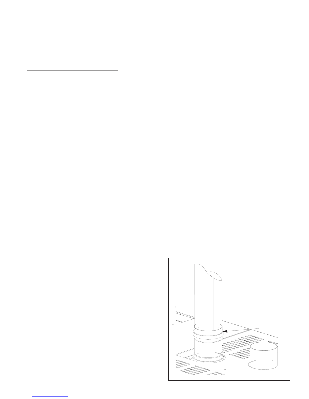
·
The vent pipe exiting the humidifier is sized for
Category III installations. A field supplied adapter
is required to increase the pipe immediately at
the exit of the humidifier. The vent pipe must be
expanded to the minimum sizes listed below for
each model, increasing as code requires.
GS 100 4” minimum diameter
GS 200 5”
GS 300/400 7”
GS 500/600 8”
·
The termination at the humidifier is a MALE
connection. Standard venting hook-ups require a
female path. It is highly recommended that a
female to female adapter be assembled onto the
humidifier to establish the proper venting
sequence. Consult with the venting manufacturer
for proper hook up.
· A maximum of 4 gas appliances may be common
vented on the same floor. Multiple story common
venting is not recommended.
· Refer to the vent manufacturers instructions for
proper clearances to combustibles.
Figure #10
Exhaust Connection
Female to Femal
Adapter
(by others)
-10-

This appliance should not be connected to a
·
chimney flue servicing a separate appliance
designed to burn solid fuel. Never connect this
humidifier to a chimney servicing a fireplace.
This venting category cannot be used in direct
·
vent applications.
Installation as a Category III Appliance
This venting system can be installed horizontally
·
or vertically and can terminate on a rooftop or
sidewall provided the NFGC (Nation Fuel Gas
Code) and CAN/CGA- B149 codes are followed.
The venting manufacturer instructions must also
be followed. See Figure # 6,#7 & #8.
WARNING: Provide a screen or barrier to prevent
personal injury in areas where inadvertent personnel
contact with vent pipe can occur.
A minimum equivalent vent length of 7 feet must
·
be connected to the humidifier. Vent lengths
must not exceed 100’ (30 m). Each 90° elbow
is equivalent to 10’ and each 45° elbow equals 5'.
The vent run should be as direct as possible with
no more than 6 elbows in the system.
Diret vent applications, length of vent should not
·
exceed 70” in equivalent length.
ADDITIONAL REQUIREMENTS WHEN VENTING
THROUGH A SIDEWALL
This venting must be used in all direct vent
·
applications.
This category installation may not be common
·
vented with any other natural draft gas appliance
or power assist appliance. The humidifier cannot
share a chimney flue servicing an appliance
designed to burn solid fuel.
· Venting must be UL or UL/CSA listed, tested to
ULC-5636 Standard. Venting may be BH or L
vent. Special gas vent shall be listed and installed
in accordance with the terms of the special gas
vent listing and the manufacture’s instructions.
The special instructions listed below should be
followed as well.
·
All joints must be sealed using high temperature
RTV silicone.
BH Vent Manufacturers
1. Flex-L International
For sidewall venting, locate the humidifier as close
as possible to the wall being used.
Locate the vent terminal at least three feet above
any forced air inlet located within ten feet; or at least
four feet below, four feet horizontally from, or one foot
above any door, window, or gravity air inlet into any
building.
A minimum horizontal clearance of four feet from
electric meters, gas meters, regulator and relief
equipment is required.
For sidewall vent terminations, the humidifier must
be installed with the certified vent terminal that can be
purchased from Nortec.
GS 100 3” Nortec P/N 1502321
GS 200 4” Nortec P/N 1502322
GS 300/400 5” Nortec P/N 1507320
GS 500/600 6” Nortec P/N 1507321
2. Fas-N Seal
3. Heat-Fab Inc.
4. Z Flex
·
The gas humidifier is supplied with the following
exhaust outlets.
GS 100 3”
GS 200 4”
GS 300/400 5”
GS 500/600 6”
·
The venting must remain the same diameter
throughout the installation.
Locate the vent terminal at least seven feet above
grade when it is adjacent to public walkways.
Locate the bottom of the vent terminal at least
twelve inches above grade or ground, or normally
expected snow accumulation level. The snow level
may be higher on walls exposed to prevailing winds.
Avoid areas where local experience indicates that
condensate drip may cause problems such as above
planters, patios, or over public walkways, or over an
area where condensate or vapor could create a
nuisance or hazard, or could be detrimental to the
operation of regulators, relief valves, or other
equipment. Refer to the vent manufacturer's
installation instructions.
-11-

The vent terminal must be installed in the same
atmospheric pressure zone as the combustion air inlet
of the humidifier. If this is not possible (as in cases of
positive or negative room pressures) the humidifier
should be installed with the direct vent option.
ELECTRICAL
PRIMARY WIRING
Field wiring from humidistat to humidifier and
between devices should be shielded 18 AWG or
heavier and kept as short as possible.
Controls are available from NORTEC as
accessories and can be ordered with the humidifier.
Controls by others may also be used as long as they
meet the criteria noted below. The following is a
summary of the common types of controls that may be
used with NORTEC Gas Humidifiers.
All work concerning the electrical installation
must be performed by qualified personnel.
WARNING: The electrical parts inside the
humidifier are very sensitive to electrostatic discharge.
Appropriate measures against electrostatic discharge
(ESD protection) must be taken when carrying out
installation work.
The humidifier should only be connected to
·
primary power (mains power) after all installation
work has been completed.
· An external disconnect switch must be installed
close to the unit to allow for power interruption
during servicing and/or maintenance.
· Humidifiers require field wiring to primary voltage
terminal blocks. Power requirement must be
120V or 208-240 Vac, 15A separately fused
circuit, single phase. Use only copper wire with a
minimum 70 °C (158 °F) temperature rating.
Wiring can be fed through a 7/8" hole on the
bottom or the top of the control compartment.
See Figure #1.
·
When installed, the appliance must be electrically
grounded in accordance with local codes or, in
the absence of local codes, with the National
Electrical Code, ANSI/NFPA 70, and/or the CSA
C22.1 Electrical Code, if an external electrical
source is utilized.
·
External wiring sizes must be in accordance with
NEC and/or CEC and existing local electrical
codes and by-laws.
Wall or Duct Mounted Control On/Off
Humidistat: Wired to make on drop in humidity,
break on rise to setpoint. Set to desired RH. Can
be a make/break set of contacts from a Building
Automation System.
Duct Mounted Safety High Limit On/Off
Humidistat: Wired to make on drop in humidity,
break on rise to safety setpoint. Set to
approximately 85% RH as a safety to prevent
saturation and wetting in the duct. Highly
recommended for ducted applications.
Duct Mounted Safety Air Proving On/Off Switch:
Wired to make when sensing air flow, break when no
air flow. Used as a safety to prevent saturation when
there is no air flow. Highly recommended for ducted
applications.
Wall or Duct Mounted Modulating Humidistat:
Provides a modulating signal to the unit that
represents the output (up to 100%) required from the
humidifier. Signal type can be changed in the field via
dip switch settings on the logic control board.
All GS models may be configured for either single
or dual channel modulation. Control signals can be
0-10 VDC or 0-20 mA (0-5 VDC, 1-5 VDC, 4-20 mA
and 2-10 VDC are also available). The unit must be
ordered from the factory for the desired signal type
and number of channels. When configured for
2-channel modulation the humidifier will generate
steam only if both channels indicate a demand. If both
channels are demanding steam the humidifier will
satisfy the lower demand signal.
LOW VOLTAGE CONTROL WIRING
All GS models require at least one type of input
control signal for unit operation. Refer to the sections
below that detail the types of controls that can be used
with each model.
Low voltage control terminal strips are provided in
the electrical compartment. Internal sides are factory
wired. External sides are to be field wired. Refer to
the specific control-wiring diagram supplied with each
unit.
-12-
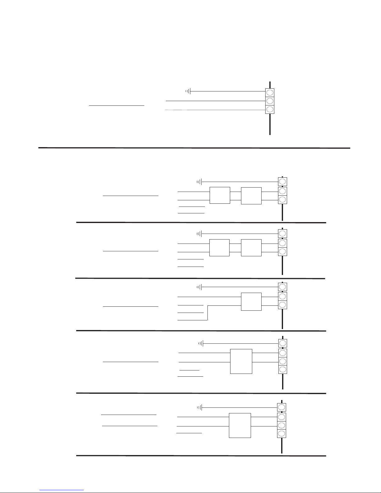
NOTE: VoltageAt TerminalBlock MustBe InAccordance With Spec.Label.
A
ll Wiring ToBeInAccordance With Existing NationalAndLocalElectricalCodes.
PRIMARY120V 1 phase line voltage wiring to unit
120V/1ph
VOLTAGE
(ACTUAL)
600V/3ph
460V/3ph
Ground Wire
E
X
N
T
T
L1
Neutral
Ground
Note:
- 120V/ 1phase Supply.
- 120V/1phase betweenhot andneutral.
- 240V/1phase betweentwo 120V/1phsupply.
PRIMARY208-240V 1 phase line voltagewiring to unit
L1
L2
L3
Neutral
L1
L2
L3
Neutral
(BY OTHERS)
Ground
Transformer
600V/208V
Note:
- 600V/3 Phase Supply.
- 600V/1ph betweenany twohot leg.
- 347V/1ph betweenhot andneutral.
Ground
Stepdown
Transformer
460V/208V
Note:
- 460V/3 Phase Supply.
- 460V/1ph betweenany twohot leg.
- 277V/1ph betweenhot andneutral.
Stepdown
byothers
byothers
Ground Wire
Ground Wire
Dedicated
Circuit
Breaker
Or
Disconnect
Dedicated
Circuit
Breaker
Or
Disconnect
I
Ground
Leg
2 Pole
Terminal
Block
E
X
T
E
X
T
L1
Neutral
Ground
Leg
2 Pole
Terminal
Block
I
N
T
Ground
Leg
2 Pole
Terminal
Block
I
N
T
380V/3ph
208V/3ph
120V/1ph
120V/1ph
L1
L2
L3
Neutral
L1
L2
L3
Neutral
L1
L2
Neutral
Ground
Note:
- 380V/3 Phase Supply.
- 380V/1 phasebetween twohot legs.
- 220V/1 phasebetween hotand neutral.
Ground
Note:
- 208V/3 Phase Supply.
- 208V/1 phasebetween twohot legs.
- 120V/1 phasebetween hotand neutral.
Ground
Note:
- 120V/ 1phase Supply.
- 120V/1phase betweenhot andneutral.
- 240V/1phase betweentwo 120V/1phsupply.
Ground Wire
Ground Wire
Dedicated
Circuit
Breaker
Or
Disconnect
Ground Wire
Dedicated
Circuit
Breaker
Or
Disconnect
Dedicated
Circuit
Breaker
Or
Disconnect
Ground
Leg
2 Pole
Terminal
Block
E
I
X
N
T
T
Ground
Leg
3 Pole
Terminal
Block
E
I
X
N
T
T
Ground
Leg
3 Pole
Terminal
Block
E
I
X
N
T
T
-13-
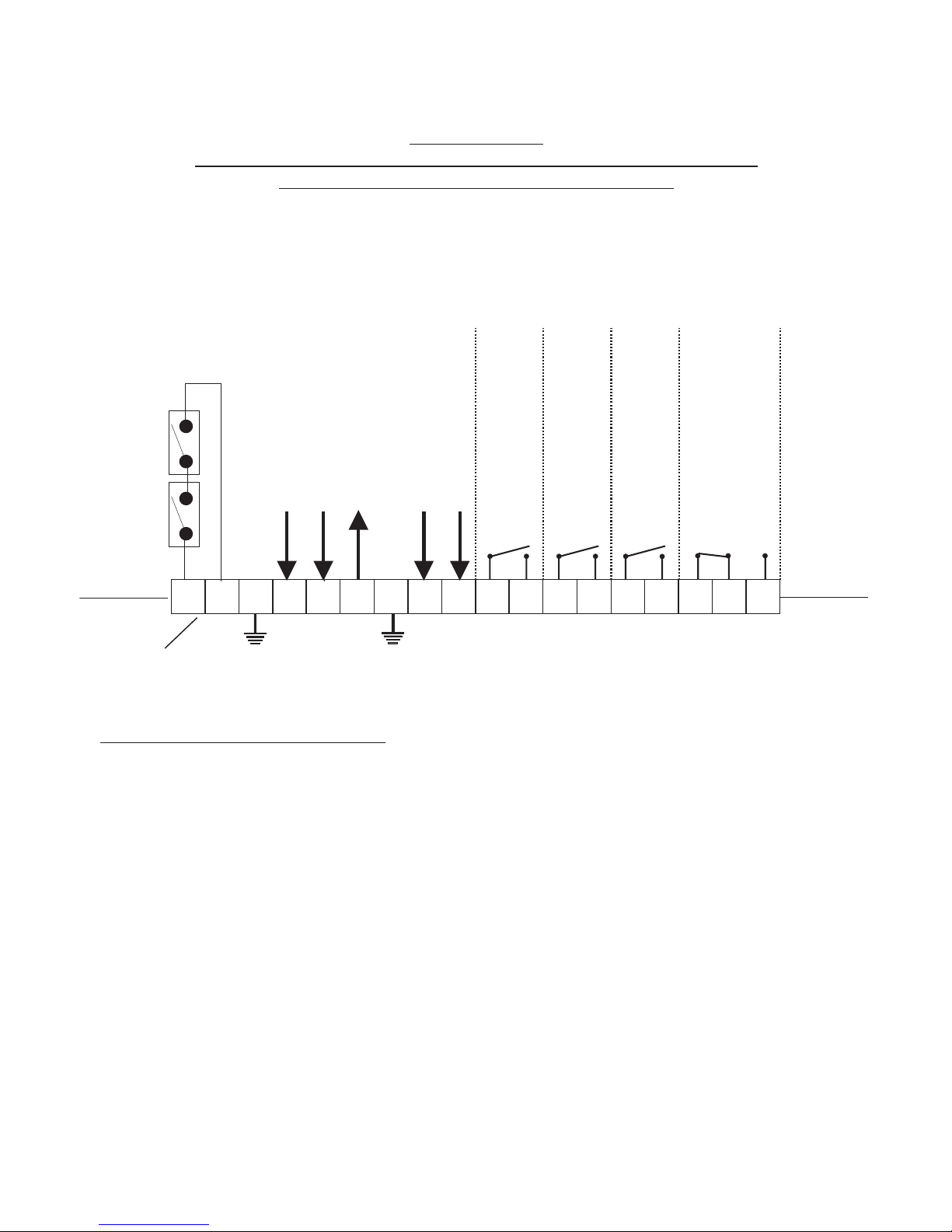
GS SERIES
EXTERNAL CONTROLS WIRING CONNECTIONS
LOW VOLTAGE TERMINAL STRIP
NOTE: This is a wiring diagram only. For specific wiring instructions, it is necessary to refer
to the wiring diagram which is supplied with each unit.
WARNING: Failure to wire the controller in accordance with the wiring diagram that was supplied
with the unit could permanently damage the GSTC/GSP board. Such errors will void the unit warranty.
Security Loop
EXTERNAL
INTERNAL
NOTE: If no On/Off Control is used then a field jumper
must be connected across terminals 1 and 2 in order
for the humidifier to operate.
1
generic
2
3
Modulation Input Signal “A"
Modulation Input Signal “B”
5
4
++
6
10 Vdc output
7
enable (24 Vac)
Full Tank Blow Down (FTBD)
8
9
Safety Interrupt (24 Vac)
COM
10
Humidifier “ON”
N.O.
1211
Humidifier “ACTIVE”
COM
13
N.O.
14
COM
Humidifier “SERVICE”
N.O.
16
N.O.
17
Humidifier “FAULT”
COM
N.C.
EXTERNAL
1815
INTERNAL
Low Voltage Terminal Strip
1 & 2: Wire all on/off controls and safeties between these two terminals. If not used, jumper1&2forthe
unit to operate.
4: Modulating input to humidifier “A”.
5: Modulating input to humidifier “B”.
6: 10 Vdc output.
8: When 24 Vac input received, the unit will initialize a full tank blowdown.
9: Safety interrupt (24 Vac).
10 & 11: Remote indication connection for humidifier “on” status indication.
12 & 13: Remote indication connection for humidifier “active” status.
14 & 15: Remote indication connection for service required indication.
16 & 17 & 18: Remote indication connection for fault indication.
-14-
CONTROL INSTALLATION
f
Mount any wall humidistat (control or high limit)
·
over standard electrical box at height similar to
typical thermostat. Any wall humidistat should be
in location representative of overall space being
humidified and not in path of blower pack or air
supply grille. Do not mount on an outside wall
where temperature fluctuations can affect control
response.
Mount duct humidistat in location representative
·
of overall air humidity, usually in return duct. Do
not mount it directly in front of steam distributor or
in turbulent or mixing zone. Mount humidistat
where air's humidity and temperature are uniform
and representative of spaces being humidified.
Mount duct high limit humidistat downstream of
·
steam distributors far enough that, under normal
humidity and air flow conditions, steam will have
been fully absorbed (typically at least 10 feet). It
must be located to sense high humidity only
when uniform and representative air is
over-humidified or approaching saturation.
· Mount duct air-proving switch so that it is able to
sense air flow or lack of it. Wire it to make when
air flow is sensed and break when air flow fails.
· Check operation of all on/off controls before
starting humidifier.
·
Calibration of controls (on/off or modulation) in
the field may be necessary due to shipping and
handling. Verify humidistat accuracy before
commissioning system.
PLUMBING
NOTE: All water supply and drain line
connections should be installed in accordance with
local plumbing codes.
FILL WATER SUPPLY LINE
It is recommended to have a faucet installed
·
close to the humidifier to allow quick filling of the
system on initial start up. This can also be very
useful for mandatory cleaning of the unit.
ALWAYS supply and install a shut off valve and
·
union in the water supply line dedicated to the
humidifier to facilitate servicing.
If water hammer occurs, install a shock arrester
·
on the fill water line just before the inlet to the fill
valve. Water hammer will damage the fill valve.
A 1” air gap is designed into the fill system of the
·
GS humidifier. Some local plumbing codes may
still require the installation of a double check
valve on the fill line to the humidifier to prevent
contamination of the supply water system. Verify
with local codes and install if necessary.
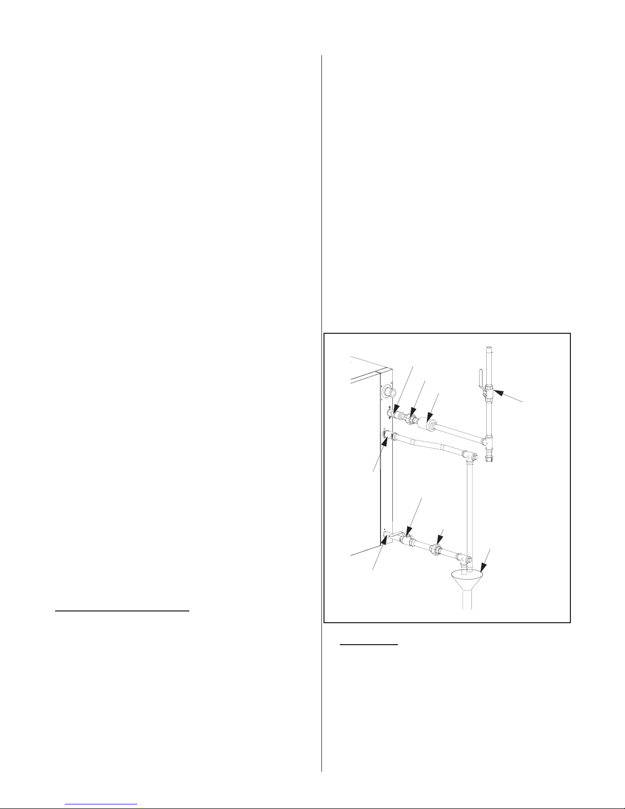
Plumbing Connections
1/2” NPT Water Supply
(by Nortec)
3/4” O.D.
Drain
(Hose clamp by Nortec)
1/2” NPT Female
Auxiliary Drain
Figure # 11
Union
(by others)
Check Valve
(by others,
if required)
Manual
Shut-off
(by others)
Union
(by others)
Manual Shut-of
(by others)
Funnel with
Air Gap (by others)
·
Each unit is supplied with an adapter for the fill
valve (½”NPT ). Fill rate 10 l/min all unit sizes.
Size of piping is a minimum ½” copper,
recommend ¾” up to within 4 feet of unit.
·
Standard fill valves are sized for water pressure
ranging from 30 to 80 psig (ideally 55 to 60 psig).
For other pressures, consult factory. This
pressure should be measured at the humidifier if
the water pressure is suspect.
-15-
DRAIN LINE
·
The humidifier is equipped with a ¾”O.D.
Unthread ed drain outlet connection on the side
of the humidifier. A vacuum break valve is
installed internal to the unit on the drain line. The
drain water line must be piped to a drain funnel to
provide an air gap before connection to the
building drainage system.
The drain line should not end in a sink used
·
frequently by personnel, or where plumbing
codes prohibit it. Route to a floor drain or
equivalent for safety reasons. Internal drain water
tempering will ensure a maximum of 140ºF
(60ºC) exiting water temperature.
Never install PVC piping as a drain line material.
·
Always use material suitable for with-standing
140ºF (60ºC).
Keep drain lines as short as possible. Keep drain
·
lines sloped down, not level and not up since low
spots in drain lines will accumulate sediment and
cause backup. The drain line should be 1-1.5"
O.D. or larger. Consult local codes.
When the drain pump is activated, the tank drains
·
at a rate of 7-8 gal/min (18-20 l/min).
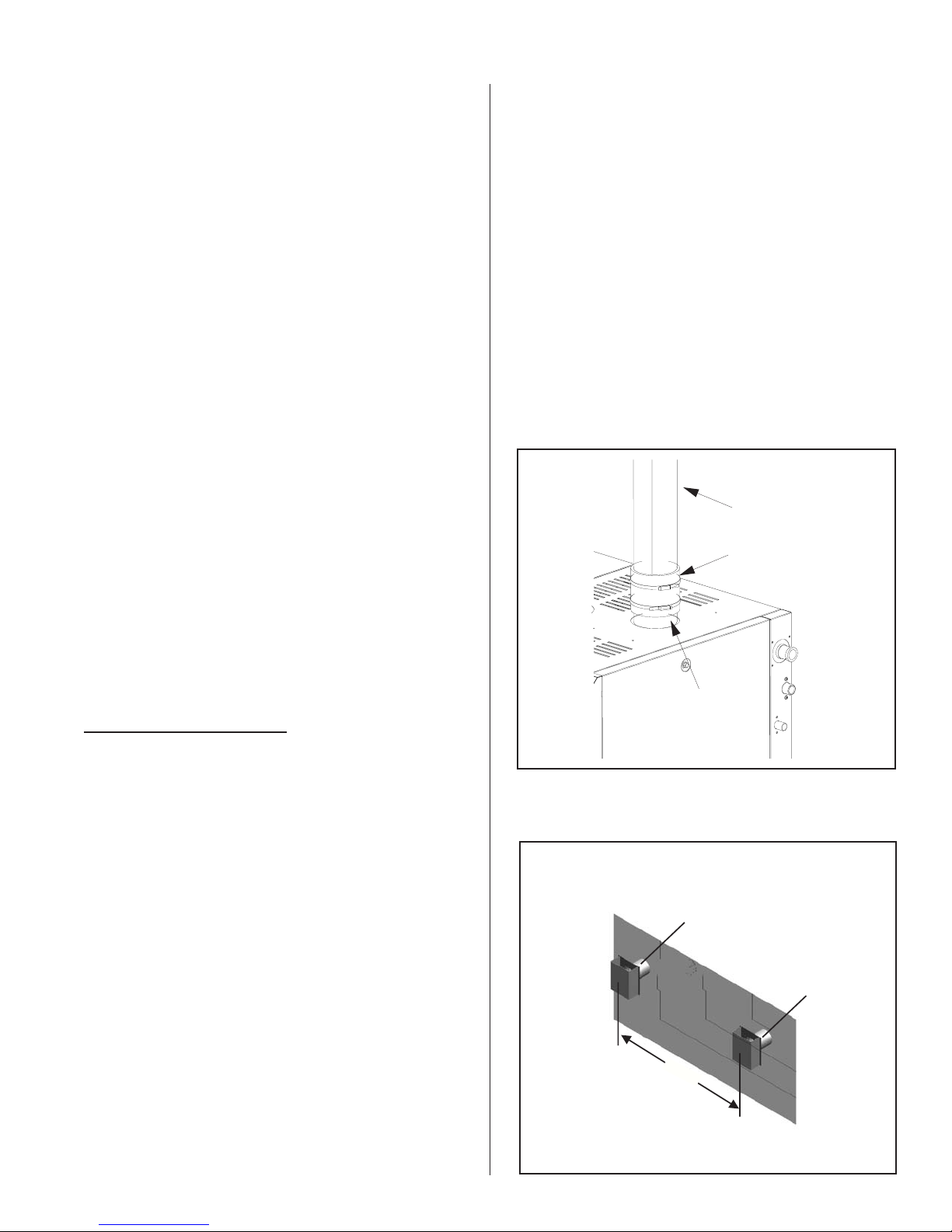
AUX DRAIN PORT
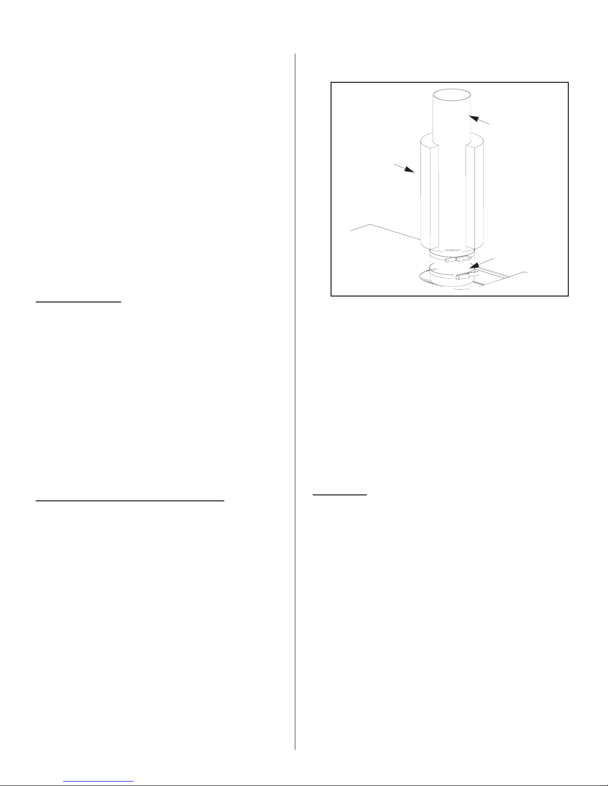
Figure #12
Steam Line Connection
Steam Line
Snap on Insulation
Hose cuffs &
clamps supplied
An auxiliary drain port is also provided on the
·
side of the humidifier. It can be used to manually
drain the unit, if required. The unit is shipped
with this connection plugged. It is recommended
to install a shut off valve on this line (see Figure
#11).
· The auxiliary drain port is used when the freeze
protection option is required. Install a shut off
valve on this line and pipe to the drain funnel (see
Figure #11). The manual shut off valve must
always be in the open position when the unit is
operating but can be closed for servicing of the
unit.
STEAM LINES AND CONDENSATE LINE
·
Steam hoses and clamps are provided with the
GS humidifier for connection to the steam lines.
Refer to Figure #12 for connection details.
·
For steam line installation between the humidifier
and distribution system, consult the distribution
system installation manual. Steam Distributor
Installation Manual - Form #XX-231 and SAM-e
Short Absorption Manifold - Form #XX-249.
·
The GS series of Gas-Steam humidifiers can
develop steam pressures up to 12”w.c. to
overcome duct and steam line pressures. An
enclosed trap on the drain line prevents steam
from going to drain. Duct pressures above 12”
will cause steam to exits through the drain line.
Consult factory.
GS Outdoor Installation
GS Outdoor units are CSA certified for outdoor
installation and come complete with exhaust venting
and internal ventilation (cooling) for the electronics.
Optional heaters for freeze protection in cold climates
are available.
All installations must conform with local building
codes or, in the absence of local codes, with the
National Fuel Gas Code ANSI Z223.1 in the United
States or CAN/CGA B149 Installation codes in
Canada. NORTEC can not accept responsibility for
installation code violations.
MOUNTING
·
Typical rooftop installations are shown in Figure
#13 & #14.
·
The GS Outdoor unit comes standard with
cutouts in the base to allow for lifting by a forklift.
When lifting by this method, ensure that the forks
extend across the entire base to prevent tipping
or damage to the unit.
·
The enclosure also comes complete with four (4)
removable lifting lugs fastened to the base. All
four lugs must be utilized if moving the unit in this
manner. Protect the cabinet from damage from
the lifting cables/chains during lifting. The lifting
lugs should be removed from the base once the
unit has been correctly positioned on the curb
mounting.
-16-
·
See Figure #15 for clearance details.
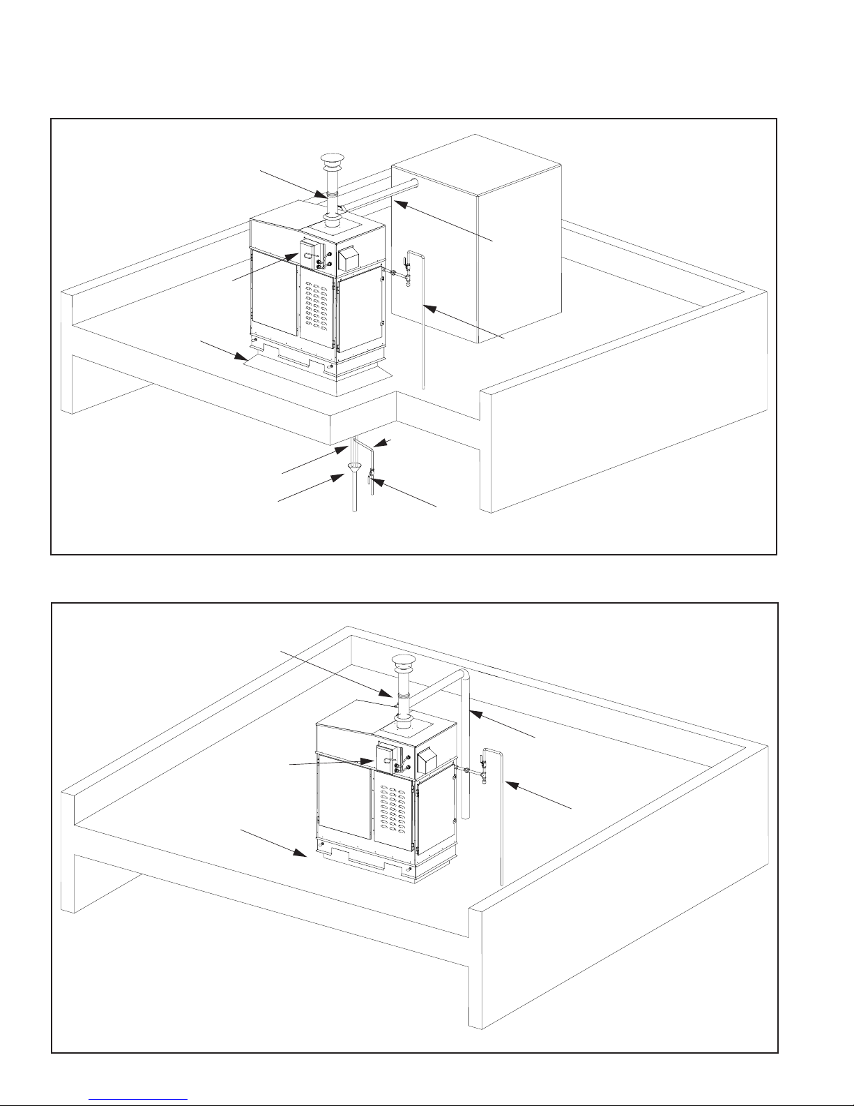
Figure # 13
GSTC Outdoor Typical Installation Rooftop
Electrical
Disconnect
(By others)
Roof Curb
(By others)
BH Vent
(By Nortec)
Drain
Lines
Funnel
With Air Gap
AHU
Insulated
Steam Line
(By others)
Gas Line with
Manual Shut-off
(By others)
Water
Supply
Manual
Shut-off
Roof Curb
(By others)
BH Vent
(By Nortec)
Electrical
Disconnect
(By others)
Figure # 14
GS Outdoor Typical Installation Rooftop
Insulated
Steam Line
(By others)
Gas Line with
Manual
Shut-off
-17-
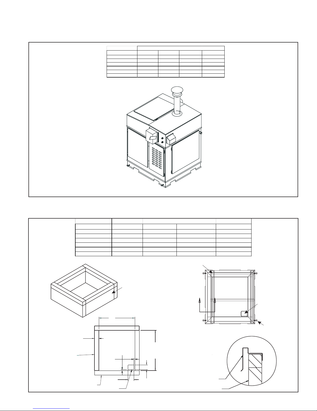
Figure # 15
GSTC Outdoor Clearance
Model Front Left Right Back
GSTC Outdoor 100 30" (76cm ) 0 40" (101.6 c m) 6" (15.25 c m)
GSTC Outdoor 200 30" (76cm ) 0 40" (101.6 c m) 6" (15.25 c m)
GSTC Outdoor 300 30" (76cm ) 30" (76cm ) 40" (101.6 c m) 6" (15.25 c m)
GSTC Outdoor 400 30" (76cm ) 30" (76cm ) 40" (101.6 c m) 6" (15.25 c m)
GSTC Outdoor 500 30" (76cm ) 30" (76cm ) 40" (101.6 c m) 6" (15.25 c m)
GSTC Outdoor 600 30" (76cm ) 30" (76cm ) 40" (101.6 c m) 6" (15.25 c m)
Minimum Required Clearances
TOP
Left
FRONT
RIGHT
3 3/4”
(9.5cm)
ELECTRICAL SIDE
Figure # 16
Roof Curb Dimensions
Roof Curb Dimensions
Model Dimension A Curb Height Shipping We ight Operating Weight
GSTC Outdoor 100 8.63" (27.91cm ) 15" (38.1cm) Min. 400 lbs (181 k g) 556 lbs (252 kg)
GSTC Outdoor 200 15.06" (38.25cm ) 15" (38.1cm) Min. 500 lbs (227 kg) 744 lbs (338 kg)
GSTC Outdoor 300 30.63" (77.8cm ) 15" (38.1c m) Min. 700 lbs (318 kg) 1185 lbs (539 k g)
GSTC Outdoor 400 30.63" (77.8cm ) 15" (38.1c m) Min. 745 lbs (339 kg) 1210 lbs (550 k g)
GSTC Outdoor 500 46.25" (117.5cm ) 15" (38.1cm) Min. 800 lbs (363 kg) 1505 lbs (684 kg)
GSTC Outdoor 600 46.25" (117.5cm ) 15" (38.1cm) Min. 844 lbs (384 kg) 1525 lbs (693 kg)
Roof Curb
by Others
AA
A
SECTION A-A
MAX.
34 1/8”
(86.6cm)
3/4”
(1.90cm)
11/16”
(1.8cm)
Pipe
Chase
Lifting
Hooks
BURNER SIDE
(15.24cm)
PIPE CHASE
6.0”
ROOF
5.0”
(12.7cm)
-18-
BASE FRAME
ELEMENT
CURB
The integral base of the GS Outdoor model is
e
·
designed to mount on a curb. The curb must be
built to structurally support the entire weight of
the humidifier when in operation. Required curb
dimensions are given in Figure #16 .
Ensure that the humidifier is mounted level.
·
The pan in the bottom of all outdoor models has
·
a pipe chase for routing of services into the
humidifier from below.
It is not necessary to make the hole in the roof
·
the same size as the curb. The curb drawing
shows the location and size of the pipe chase
required. The pipe chase should be sealed when
the installation is complete to ensure positive or
negative pressure from the building.
The panels of the outdoor model have louvers to
·
provide ventilation for the electronics and air for
the combustion process. Locate the unit so that
louvered panels are a minimum of 10 ft from any
mechanical exhaust outlet.
· When mounted on the curb, the lowest air intake
louvers must be a minimum of 12” above any
surface where snow or ice could accumulate. In
areas where normal snow accumulation is
higher, mount the unit accordingly.
· Do not store or use gasoline or other flammable
vapors and liquids in the vicinity of the humidifier.
·
The humidifier may be installed directly on
combustible flooring or, in the U.S., on wood
flooring or Class A, Class B or Class C roof
covering materials.
Gas lines are to be routed to the outside
·
connection on the right side near the back of the
unit. The installation of a sediment trap and a
certified manual shut-off valve are required
outside of the unit. The gas piping must not block
access to or prevent opening of the right side
service door. Refer to Figure #17 for details.
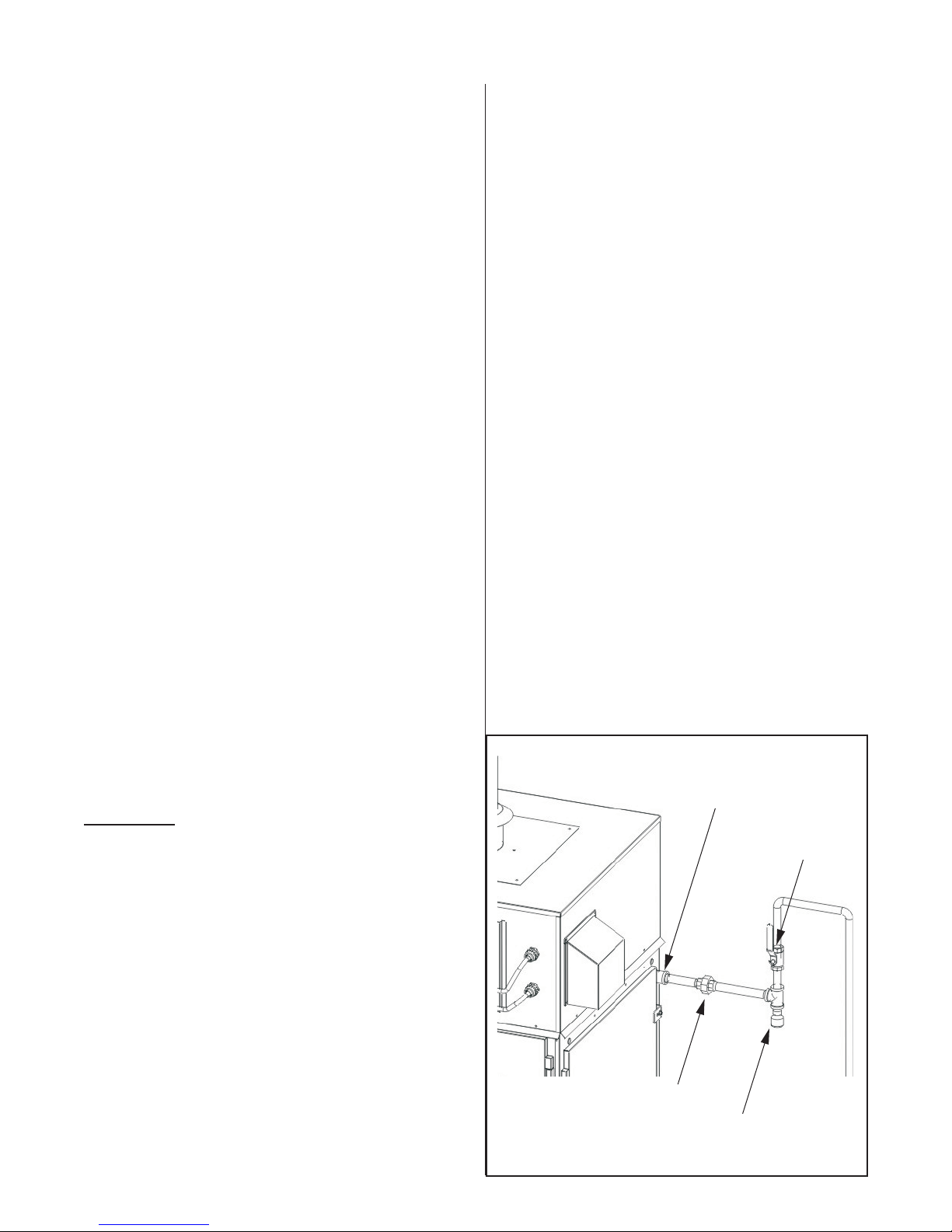
Nortec recommends that each Gas Fired
·
Humidifier has it’s own regulator installed in line to
the unit. Th operating Natural Gas pressure
supplied for the GS units must be in the range of
5-9 “ of Water Column and propane version
10-14” of Water Column.
Over pressure protection devices shall be
·
provided to prevent the pressure in the piping
system from exceeding that value that would
cause unsafe operation of any connected and
properly adjusted Gas utilization equipment. See
Figure #18
If the system has a pressure that is higher than
·
the max working pressure of our humidifier, then
an Over pressure protection system is required. If
there is an Over pressure protection device
installed, it MUST consist of 2 devices in series.
(A pressure regulator plus one other device) Both
these devices must be able to work on their own
without damaging any downstream piping or
appliance, and the only way the downstream
Figure #17
Gas Piping
Inlet coupling supplied
GAS PIPING
·
Installation of piping must be in accordance with
local codes, and the National Fuel Gas Code
ANSI Z223.1 in the United States or
CAN/CGA-B149 Installation Codes in Canada.
·
Refer to the indoor gas piping installation
guidelines for gas line sizes, pressures, leak
testing procedures, and safety instructions.
Shut-off Gas Valv
(by others)
Union
(by others)
Sediment Trap
(by others)
-19-
(By
)
d
Figure #18
GasPiping
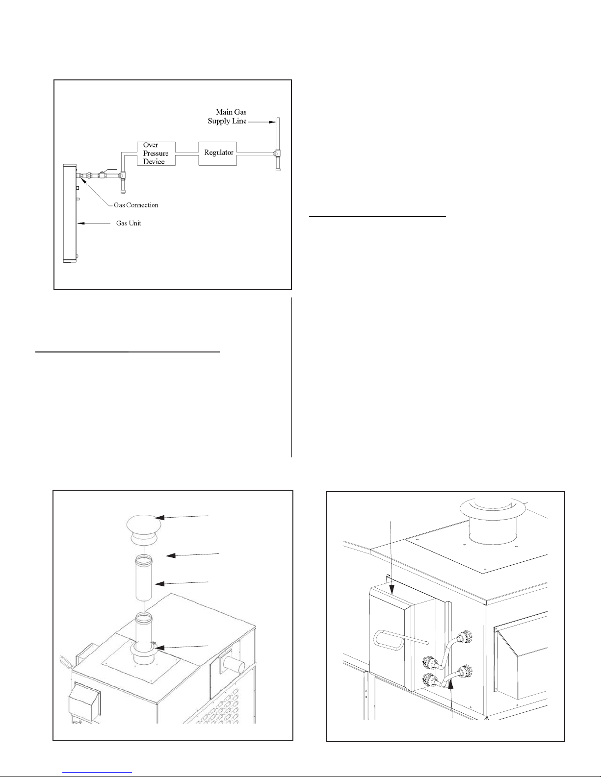
Each vent length and the rain cap have a built-in
·
mechanical locking band and gasket. Simply
push together each component to the stop bead,
which provides an air & water-tight seal. Then
tighten the integrated locking band on each
component to complete the installation of the
exhaust venting.
The rain cap must extend at least 2 feet above
·
any ridge within 10 feet of the unit. The exhaust
venting can be extended using additional vent
lengths purchased from Nortec.
ELECTRICAL INSTALLATION
Power and control wiring is to be routed into the
·
humidifier through the pipe chase in the base pan
of the outdoor models located in the burner area.
Installation details for primary and low voltage
·
control wiring are the same as for indoor units.
system can be damaged is by the failure of both
devices.
EXHAUST VENTING
- OUTDOOR UNITS
· All required exhaust venting is provided with each
GS Outdoor model, by Nortec, including rain cap
and storm collar. All venting components
external to the unit are shipped with the unit and
must be installed on site. Refer to Figure #19 for
venting components.
Figure #19
Exhaust - Outdoor Units
Rain Cap
All Venting provide
by Nortec
Extension Pipe
A field supplied NEMA rated weatherproof
·
disconnect switch must be mounted external to
the GS Outdoor unit to allow for power
interruption during servicing and/or maintenance.
A mounting plate, located on the front of each
outdoor model above the electrical access door,
is available for mounting of the disconnect switch.
Two electrical conduits are provided for routing
the primary wiring to the disconnect switch and
then back inside the enclosure to the main power
terminal strip. See Figure #20 for details.
Figure #20
Electrical Box
Disconnect box
(By others)
Storm Collar
Primary wiring
others
-20-
 Loading...